EP1210974A2 - Bone cement mixing apparatus having particular mixing blade configuration - Google Patents
Bone cement mixing apparatus having particular mixing blade configuration Download PDFInfo
- Publication number
- EP1210974A2 EP1210974A2 EP01310040A EP01310040A EP1210974A2 EP 1210974 A2 EP1210974 A2 EP 1210974A2 EP 01310040 A EP01310040 A EP 01310040A EP 01310040 A EP01310040 A EP 01310040A EP 1210974 A2 EP1210974 A2 EP 1210974A2
- Authority
- EP
- European Patent Office
- Prior art keywords
- mixing
- bone cement
- blade
- canister
- shaft
- Prior art date
- Legal status (The legal status is an assumption and is not a legal conclusion. Google has not performed a legal analysis and makes no representation as to the accuracy of the status listed.)
- Granted
Links
Images


Classifications
-
- B—PERFORMING OPERATIONS; TRANSPORTING
- B01—PHYSICAL OR CHEMICAL PROCESSES OR APPARATUS IN GENERAL
- B01F—MIXING, e.g. DISSOLVING, EMULSIFYING OR DISPERSING
- B01F33/00—Other mixers; Mixing plants; Combinations of mixers
- B01F33/50—Movable or transportable mixing devices or plants
- B01F33/501—Movable mixing devices, i.e. readily shifted or displaced from one place to another, e.g. portable during use
- B01F33/5011—Movable mixing devices, i.e. readily shifted or displaced from one place to another, e.g. portable during use portable during use, e.g. hand-held
-
- A—HUMAN NECESSITIES
- A61—MEDICAL OR VETERINARY SCIENCE; HYGIENE
- A61B—DIAGNOSIS; SURGERY; IDENTIFICATION
- A61B50/00—Containers, covers, furniture or holders specially adapted for surgical or diagnostic appliances or instruments, e.g. sterile covers
- A61B2050/005—Containers, covers, furniture or holders specially adapted for surgical or diagnostic appliances or instruments, e.g. sterile covers with a lid or cover
- A61B2050/0062—Containers, covers, furniture or holders specially adapted for surgical or diagnostic appliances or instruments, e.g. sterile covers with a lid or cover closable by a combination of rotation and translation
- A61B2050/0064—Containers, covers, furniture or holders specially adapted for surgical or diagnostic appliances or instruments, e.g. sterile covers with a lid or cover closable by a combination of rotation and translation by screwing
-
- A—HUMAN NECESSITIES
- A61—MEDICAL OR VETERINARY SCIENCE; HYGIENE
- A61F—FILTERS IMPLANTABLE INTO BLOOD VESSELS; PROSTHESES; DEVICES PROVIDING PATENCY TO, OR PREVENTING COLLAPSING OF, TUBULAR STRUCTURES OF THE BODY, e.g. STENTS; ORTHOPAEDIC, NURSING OR CONTRACEPTIVE DEVICES; FOMENTATION; TREATMENT OR PROTECTION OF EYES OR EARS; BANDAGES, DRESSINGS OR ABSORBENT PADS; FIRST-AID KITS
- A61F2/00—Filters implantable into blood vessels; Prostheses, i.e. artificial substitutes or replacements for parts of the body; Appliances for connecting them with the body; Devices providing patency to, or preventing collapsing of, tubular structures of the body, e.g. stents
- A61F2/02—Prostheses implantable into the body
- A61F2/30—Joints
- A61F2002/30001—Additional features of subject-matter classified in A61F2/28, A61F2/30 and subgroups thereof
- A61F2002/30003—Material related properties of the prosthesis or of a coating on the prosthesis
- A61F2002/3006—Properties of materials and coating materials
- A61F2002/3009—Transparent or translucent
-
- A—HUMAN NECESSITIES
- A61—MEDICAL OR VETERINARY SCIENCE; HYGIENE
- A61F—FILTERS IMPLANTABLE INTO BLOOD VESSELS; PROSTHESES; DEVICES PROVIDING PATENCY TO, OR PREVENTING COLLAPSING OF, TUBULAR STRUCTURES OF THE BODY, e.g. STENTS; ORTHOPAEDIC, NURSING OR CONTRACEPTIVE DEVICES; FOMENTATION; TREATMENT OR PROTECTION OF EYES OR EARS; BANDAGES, DRESSINGS OR ABSORBENT PADS; FIRST-AID KITS
- A61F2/00—Filters implantable into blood vessels; Prostheses, i.e. artificial substitutes or replacements for parts of the body; Appliances for connecting them with the body; Devices providing patency to, or preventing collapsing of, tubular structures of the body, e.g. stents
- A61F2/02—Prostheses implantable into the body
- A61F2/30—Joints
- A61F2/46—Special tools or methods for implanting or extracting artificial joints, accessories, bone grafts or substitutes, or particular adaptations therefor
- A61F2002/4685—Special tools or methods for implanting or extracting artificial joints, accessories, bone grafts or substitutes, or particular adaptations therefor by means of vacuum
-
- A—HUMAN NECESSITIES
- A61—MEDICAL OR VETERINARY SCIENCE; HYGIENE
- A61F—FILTERS IMPLANTABLE INTO BLOOD VESSELS; PROSTHESES; DEVICES PROVIDING PATENCY TO, OR PREVENTING COLLAPSING OF, TUBULAR STRUCTURES OF THE BODY, e.g. STENTS; ORTHOPAEDIC, NURSING OR CONTRACEPTIVE DEVICES; FOMENTATION; TREATMENT OR PROTECTION OF EYES OR EARS; BANDAGES, DRESSINGS OR ABSORBENT PADS; FIRST-AID KITS
- A61F2250/00—Special features of prostheses classified in groups A61F2/00 - A61F2/26 or A61F2/82 or A61F9/00 or A61F11/00 or subgroups thereof
- A61F2250/0058—Additional features; Implant or prostheses properties not otherwise provided for
- A61F2250/0091—Additional features; Implant or prostheses properties not otherwise provided for transparent or translucent
-
- B—PERFORMING OPERATIONS; TRANSPORTING
- B01—PHYSICAL OR CHEMICAL PROCESSES OR APPARATUS IN GENERAL
- B01F—MIXING, e.g. DISSOLVING, EMULSIFYING OR DISPERSING
- B01F2101/00—Mixing characterised by the nature of the mixed materials or by the application field
- B01F2101/20—Mixing of ingredients for bone cement
-
- B—PERFORMING OPERATIONS; TRANSPORTING
- B01—PHYSICAL OR CHEMICAL PROCESSES OR APPARATUS IN GENERAL
- B01F—MIXING, e.g. DISSOLVING, EMULSIFYING OR DISPERSING
- B01F35/00—Accessories for mixers; Auxiliary operations or auxiliary devices; Parts or details of general application
- B01F35/30—Driving arrangements; Transmissions; Couplings; Brakes
- B01F35/32—Driving arrangements
- B01F35/32005—Type of drive
- B01F35/3202—Hand driven
Definitions
- the present invention relates generally to a surgical assembly, and more particularly to an apparatus and method for mixing bone cement.
- cement or grouting type agent such as for attaching artificial joint implants, repairing or forming joints in bones, or other forms of orthopaedic work.
- the type of cement generally used for these purposes is a self-curing resin formed from the blending of a wide variety of liquid monomers or co-monomers with powdered polymers or copolymers to form a viscous admixture to be used as the grouting agent.
- the admixture of the powder and liquid components develops a quick setting material.
- preparation of the cement usually occurs directly within the operating area just prior to use.
- a bone cement mixing apparatus is generally utilized to mix the powder and liquid components in the operating area.
- the resultant admixture is then removed from the mixing apparatus and placed in a cement delivery apparatus for subsequent use by the surgeon.
- the bone cement must generally first be scooped or otherwise removed from the mixing apparatus and thereafter placed in a syringe-type delivery apparatus for use by the surgeon.
- the system described above for mixing and delivering bone cement has a number of drawbacks associated therewith.
- monomer vapours are generated during the depositing of the monomer into the mixing apparatus and during the subsequent mixing of the monomer with the powder component of the bone cement.
- Such monomer vapours may be noxious and/or toxic.
- the bone cement is generally mixed in the operating room environment, it is important to prevent any monomer or its vapours from escaping the mixing apparatus.
- heretofore designed mixing apparatus have not included mechanisms for controlling the escape of such vapours.
- heretofore designed mixing apparatus have been plagued with problems relating to the incomplete mixing of the liquid component and the powder component. Specifically, the powder component and liquid component are often inadequately mixed during operation of heretofore designed systems. Such a problem is further compounded by the fact that heretofore designed mixing vessels are not transparent thereby preventing the contents of the vessel (i.e. the bone cement) from being viewed by the operator of the mixing apparatus.
- the system described above also suffers from operational inefficiencies relating to the need to transfer the mixed bone cement from the mixing apparatus to the delivery apparatus.
- the need to remove the mixed bone cement from one device (i.e. the mixing apparatus) and place it in a second device (i.e. the delivery device) creates an extra step in the process thereby increasing the time necessary to deliver the mixed bone cement.
- a quantity of the bone cement is lost in the process since it is highly unlikely that all of the mixed cement is actually removed from the mixing apparatus and placed in the delivery apparatus.
- What is needed therefore is an apparatus and method for mixing a bone cement which overcomes one or more of the above-mentioned drawbacks. What is particularly needed is an apparatus and method for mixing bone cement which reduces, if not eliminates, exposure to vapours from the liquid bone cement component within the operating area. What is further needed is an apparatus and method for mixing bone cement which may also be utilized to delivery the mixed bone cement. What is moreover needed is an apparatus and method for mixing bone cement which reduces, or even eliminates, the occasions in which a portion of the powder cement component is not thoroughly mixed with the liquid cement component.
- a bone cement mixing apparatus in accordance with the concepts of the present invention, there is provided a bone cement mixing apparatus.
- the bone cement mixing apparatus includes a handle, and a canister defining a mixing chamber.
- the bone cement mixing apparatus further includes a mixing blade which is caused to rotate in response to movement of the handle, the mixing blade being positioned within the mixing chamber.
- the mixing blade includes a shaft and at least one vane supported by the shaft. Also, the shaft has defined therein (i) an inlet orifice, (ii) a plurality of outlet orifices, and (iii) a passageway which places the inlet orifice in fluid communication with each of the plurality of outlet orifices.
- a method of mixing bone cement includes the step of (i) placing a powder bone cement component within a canister, (ii) sealing the canister after the placing step, (iii) advancing a liquid bone cement component through a mixing blade located within the canister after the sealing step, and (iv) rotating the mixing blade after the liquid bone cement component is advanced through the mixing blade.
- the mixing blade includes (i) an inlet orifice, (ii) a plurality of outlet orifices, and (iii) a passageway which places the inlet orifice in fluid communication with each of the plurality of outlet orifices.
- the advancing step includes the step of advancing the liquid bone cement component (i) into the mixing blade through the inlet orifice, (ii) through the passageway, and (iii) out of the mixing blade through the plurality of outlet orifices.
- the bone cement mixing apparatus includes a container defining a mixing chamber. Further, the bone cement mixing apparatus includes a mixing blade positioned within the mixing chamber, the mixing blade defining (i) an inlet orifice, (ii) a plurality of outlet orifices, and (iii) a passageway which places the inlet orifice in fluid communication with each of the plurality of outlet orifices.
- a bone cement mixing apparatus which includes a handle.
- the bone cement mixing apparatus further includes a first canister segment defining a first mixing chamber portion, and a second canister segment defining a second mixing chamber portion.
- the bone cement mixing apparatus includes a mixing blade which is caused to rotate in response to movement of the handle. The mixing blade is located within both the first mixing chamber portion and the second mixing chamber portion.
- the first canister segment includes a first coupling
- the second canister segment includes a second coupling. The first coupling cooperates with the second coupling so as to secure the first canister segment to the second canister segment.
- FIGS. 1-7 show a bone cement mixing device 10 which can receive a quantity of a powder bone cement component and a liquid bone cement component (e.g. a monomer) and thereafter mix the powder component and liquid component together.
- the bone cement mixing device 10 is also operable as a bone cement delivery device thereby eliminating the need to utilize a separate delivery device.
- the mixing device 10 includes a canister 12 having a mixing chamber 14 defined therein.
- the canister 12 is preferably embodied as a pair of identical cylindrically-shaped cartridges 16, 18. Use of the cartridges 16, 18 allows for modular construction of the mixing device 10 while also reducing the number of different components which are utilized in the design thereof.
- Each of the cartridges 16, 18 is preferably constructed of a transparent material such as a transparent plastic material.
- a transparent material such as a transparent plastic material.
- Such use of a transparent material in the construction of the cartridges 16, 18 is advantageous in that the operator the mixing device may visually observe the contents within the mixing chamber 14 (i.e. the powder and liquid cement components) in order to visually determine if the components have been adequately (i.e. thoroughly) mixed with one another.
- the cartridges 16, 18 may be constructed to accommodate any quantity of bone cement.
- the cartridges 16, 18 are constructed to hold and mix at least 120 grams of powder bone cement component and the associated quantity of the liquid bone cement component (i.e. the monomer).
- Such a configuration is advantageous in that surgical procedures commonly require the preparation of three (3) batches of bone cement powder (with each batch being 40 grams). It is often necessary when using a heretofore designed mixing apparatus for each of the three batches to be prepared (i.e. mixed) separately thereby potentially creating delays and/or timing difficulties within the operating area during a surgical procedure.
- the mixing device 10 of the present invention overcomes this limitation by being configured to mix all three of the batches simultaneously.
- the upper end 20 of each of the cartridges 16, 18 has a first number of threads 22 defined therein, whereas the lower end 24 of each of the cartridges 16, 18 has a corresponding number of threads 26 defined therein.
- the threads 22, 26 may be threadingly engaged with one another (as in the case of the junction between the cartridges 16, 18), or may be engaged to a number of other components.
- the threads 22 of the upper end 20 of the cartridge 16 are threadingly engaged with a number of threads 28 associated with a mixing head assembly 30.
- the threads 26 of the lower end 24 of the canister 18, on the other hand, are threadingly engaged with a number of threads 32 defined in a base 34.
- sealing members such as O-rings 158 (see FIGS. 7, 9, and 23) are preferably utilized at each threaded coupling (i.e. between the cartridges 16, 18, between the cartridge 16 and the mixing head assembly 30, and between the cartridge 18 and the base 34).
- the mixing head assembly 30 includes an upper gear housing 36 and a lower gear housing 38.
- the upper gear housing 36 is press fit or otherwise secured to the lower gear housing 38.
- the mixing head assembly 30 also includes a crank 40 which is rotatably secured to the upper gear housing 36.
- the crank 40 includes an elongated arm 42 having a knob 44 rotatably secured to an end thereof.
- the upper gear housing 36 and the lower gear housing 38 cooperate to house a gear train 46 which is driven by rotation of the crank 40.
- the gear train 46 includes an output pinion 48 which is rotatably coupled to the lower gear housing 38.
- the output pinion 48 includes a downwardly extending coupling portion 50 which extends through an aperture 51 defined in the lower gear housing 38 (see also FIG. 13).
- the coupling portion 50 of the output pinion 48 is non-rotatably secured to an upper end 106 of a mixing blade 52.
- the coupling portion 50 of the output pinion 48 includes a number of barbs 58 which are received into a corresponding number of slots 60 (see FIGS. 7 and 9) defined in a coupling portion 108 of the mixing blade 52.
- rotation of the output pinion 48 causes similar rotation (i.e. in the same direction and at the same angular velocity) of the mixing blade 52.
- the mixing head assembly 30 is shown in greater detail.
- the mixing head assembly 30 also includes a directional gear 54, an idler gear 56, and the output pinion 48.
- the directional gear 54, the idler gear 56, and the output pinion 48 are housed within the housing defined by the upper gear housing 36 and the lower gear housing 38.
- the output pinion 48 has a shoulder 60 defined therein.
- the shoulder 60 of the output pinion 48 contacts a retaining surface 62 of the gear housing 38 (see FIG. 13) thereby retaining the output opinion 48 while also allowing it to rotate relative to the gear housing 38.
- the idler gear 56 has an aperture 64 defined therein (see FIG. 12) which is received around a post 66 (see FIGS. 13 and 14) defined in the lower gear housing 38 thereby rotatably securing the idler gear 56 to the lower gear housing 38.
- the other end of the idler gear 56 has a post 68 extending therefrom which is received into a slot 70 defined in the body 72 of the directional gear 54 (see FIGS. 10 and 17).
- the post 68 is captured by or is otherwise retained within the slot 70 during rotation of the directional gear 54.
- the directional gear 54 is non-rotatably secured to the crank 40 by use of a hexagonally-shaped coupling mechanism 74.
- the crank 40 has a hexagonally-shaped member 76 extending downwardly therefrom, whereas the body 72 of the directional gear 54 has a slightly larger hexagonally-shaped member 78 extending upwardly therefrom.
- a shoulder 80 of the crank is positioned in contact which a bearing surface 82 defined on the upper surface of the upper gear housing 36 (see FIG. 13) thereby allowing the hexagonally-shaped member 76 of the crank 40 to extend through a housing opening 84 defined in the upper gear housing 36.
- the hexagonally-shaped member 76 of the crank 40 may be press fit or otherwise received into the hexagonally-shaped member 78 of the directional gear 54 which is positioned within the upper gear housing 36 (see FIG. 11).
- rotation of the crank 40 relative to the upper gear housing 36 causes similar rotation of the directional gear 54 relative to the upper gear housing 36.
- the directional gear 54 is caused to rotate about a central axis CA as shown in FIG 17.
- the idler gear 56 meshes with both the directional gear 54 and the output pinion 48.
- the directional gear 54 includes a first number of gear teeth 86 defined in the body 72 thereof.
- the gear teeth 86 are positioned around a portion of the periphery of an aperture 88 which defines the axis of rotation of the directional gear 54.
- the directional gear 54 also includes a second number of gear teeth 90 defined in the body 72 thereof.
- the gear teeth 90 are spaced radially outwardly from the gear teeth 86.
- the gear teeth 86 and the gear teeth 90 selectively meshes with the idler gear 56 so as to selectively drive the output pinion 48 (and hence the mixing blade 52) at varying velocities and directions of rotation.
- the central axis CA lies in a plane P which divides the directional gear 54 into a first directional gear side and a second directional gear side (see e.g. FIG. 17).
- the directional gear 54 is configured so that (i) the gear teeth 86 are positioned entirely on the first input gear side, and (ii) the gear teeth 90 are positioned entirely on the second input gear side as shown in FIG. 17.
- the idler gear 56 has a number of gear teeth 92 defined therein, whereas the output pinion 48 has a number of gear teeth 94 defined therein.
- the gear teeth 92 of the idler gear 56 meshes with the gear teeth 94 of the output pinion 48.
- rotation of the idler gear 56 in a given direction causes rotation of the output pinion 48 in the opposite direction.
- clockwise rotation of the idler gear 56 causes counterclockwise rotation of the output pinion 48, and vice versa.
- the gear teeth 92 of the idler gear 56 are engaged by either the inner gear teeth 86 or the outer gear teeth 90 of the directional gear 54 during rotation of the directional gear 54.
- the idler gear 56 is initially engaged by the outer gear teeth 90 of the directional gear 54 thereby causing the idler gear 56 to likewise be rotated in the counterclockwise direction (as indicated by the arrow 96).
- Rotation of the idler gear 56 in the counterclockwise direction causes rotation of the output pinion 48 (and hence the mixing blade 52) in the opposite direction (i.e. in a clockwise rotation as viewed from the bottom perspective view of FIGS. 15-17 and designated by the arrow 98).
- crank 40 is rotated in the opposite direction (i.e. so as to cause rotation of the directional gear 54 in the clockwise direction as viewed in FIGS. 15-17 and indicated by arrow 98)
- the idler gear 56 and the output pinion 48 are rotated in the respective opposite directions to that as described above.
- rotation of the directional gear 54 in the clockwise direction i.e. in the direction of arrow 98 of FIGS. 15-17
- rotation of the directional gear 54 in the clockwise direction causes (1) clockwise rotation of the idler gear 56, and (2) counterclockwise rotation of the output pinion 48 (and hence the mixing blade 52) when the idler gear 56 is meshes with the outer gear teeth 90.
- rotation of the directional gear 54 in the clockwise direction i.e.
- the gear train 46 of the present invention is configured such that the direction of rotation of the output pinion 48 changes despite rotation of the crank 40 in only a single direction. Specifically, as the idler gear 56 is engaged with the outer gear teeth 90, the output pinion 48 and hence the mixing blade 52 is rotated in a first direction. However, as the idler gear 56 disengages the outer gear teeth 90 and engages the inner gear teeth 86, the direction of travel of the output pinion 48 and hence the mixing blade 52 is reversed thereby creating alternating or reciprocating motion.
- the relatively large number of individual gear teeth associated with the outer gear teeth 90 creates a relatively large gear ratio with the idler gear 56 relative to the gear ratio created by inner gear teeth 86 and the idler gear 56, varying angular distances of travel and speeds of the mixing blade 52 are created.
- the relatively high gear ratio created by the outer gear teeth 90 causes the output pinion 48 to be driven across a greater angular distance when the idler gear 56 is engaged with the outer gear teeth 90 relative to the angular distance across which the output pinion 48 is driven when the idler gear 56 is engaged with the inner gear teeth 86.
- the output pinion 48 (and hence the mixing blade 52) is driven across 540° of rotation when the idler gear 56 is engaged with the outer drive teeth 90, whereas the output pinion (and hence the mixing blade 52) is only advanced across 135° of rotation (in the opposite direction) when the idler gear 56 is engaged with the inner drive teeth 86.
- the mixing blade 52 is driven across 540° of rotation in a first direction and then reversed and driven across 135° of rotation in the opposite direction.
- the relatively high gear ratio created by the outer gear teeth 90 also causes the output pinion 48 to be driven at a greater angular velocity when the idler gear 56 is engaged with the outer gear teeth 90 relative to the angular velocity at which the output pinion 48 is driven when the idler gear 56 is engaged with the inner gear teeth 86.
- the output pinion 48 (and hence the mixing blade 52) is driven at a velocity which is approximately three times greater than the velocity at which the output pinion 48 (and hence the mixing blade 52) is driven when the idler gear 56 is engaged with the inner drive teeth 86.
- the mixing blade 52 is driven three times as quickly in the first direction as it is when reversed and driven in the opposite direction.
- the configuration of the directional gear 54 described herein is exemplary in nature and may be altered to fit the requirements of a given design of the mixing device 10.
- the number of teeth included in the gear teeth 86 and 90 may be varied in order to produce a desired gear ratio. Such modification to the gear teeth 86 and 90 would allow for modification to the angular distance and speed at which the mixing blade 52 is driven during rotation of the crank 40 by the operator.
- the drive characteristics of the mixing head assembly 30 which are described above provide numerous advantages to the mixing device 10 of the present invention relative to heretofore designed mixing devices.
- the reciprocating movement of the mixing blade 52 i.e. at varying angular distances and speeds
- Such agitation increases the mix quality of the mixing device 10 by reducing, if not eliminating, the amount of the powder component which is not thoroughly mixed with the liquid component.
- the mixing blade 52 includes an elongated central shaft 104 having an upper end 106 which includes the coupling portion 108 for securing the shaft 104 of the blade 52 to the coupling portion 50 of the output pinion 48.
- the shaft 104 also has a lower end 108 which extends downwardly and into contact with a plunger 110.
- the plunger 110 is made from a plastic material such as polyethylene.
- the plunger 110 includes a recess 112 which receives a tip 114 of the shaft 104 thereby providing mechanical support for the shaft 104 during rotation thereof.
- the mixing blade 52 may be configured as a "two-dimensional" (i.e. flat) blade, or alternatively, may be configured as a "three dimensional" blade.
- the vanes 116 may be configured to extend outwardly in only two directions from the shaft 104
- the vanes 116 of the mixing blade 52 may also be configured to extend outwardly from the shaft 104 in three directions. In such a three dimensional configuration, the mixing blade 52 is not substantially flat when positioned on a relatively flat surface, but rather extends in a number of different directions (including upwardly) from the flat surface.
- the vanes 116 are oriented in somewhat of a helical configuration around the shaft 104.
- Such a configuration provides numerous advantages to the mixing device 10 of the present invention.
- the helical configuration of the mixing blade 52 generates a desirable amount of "turbulence" within the mixing chamber 14 of the canister 12 thereby increasing the mixing efficiency of the mixing device 10.
- the shaft 104 of the mixing blade 52 has an elongated fluid passageway 118 defined therein.
- the fluid passageway 118 extends from the upper end 106 of the shaft 104 to the lower end 108 of the shaft 104.
- the fluid passageway 118 is placed in fluid communication with the mixing chamber 14 of the canister 12 via a number of fluid orifices 120 defined in the shaft 104. While seven (7) fluid orifices 120 are shown defined in the shaft 104, it should be appreciated that there may be more than seven (7) fluid orifices defined in the shaft 104 (e.g. nine or ten fluid orifices). Alternatively, there may be less than seven (7) fluid orifices defined in the shaft 104 (e.g. two or three fluid orifices).
- the fluid passageway 118 and the fluid orifices 120 allow for the introduction of the liquid cement component (e.g. the monomer) without exposing the operator to any vapours or fumes from therefrom.
- the crank 40 has a monomer delivery port 122 defined therein (see also FIG. 12).
- a tube 124 (see FIG. 7) is press fit into the lower end of the delivery port 122 and extends downwardly through the aperture 88 defined in the directional gear 54 and a similar aperture 126 defined in the output pinion 48 (see FIGS. 9, 12, 15, and 16).
- the lower end of the tube 124 is press fit or otherwise positioned in the coupling portion 108 of the mixing blade 52 so as to be in fluid communication with the fluid passageway 118 defined in the shaft 104.
- a quantity of liquid cement component may be introduced into the mixing chamber 14 of the canister 12 through the delivery port 122.
- the liquid cement component e.g. the monomer
- the monomer may be delivered at various locations throughout the depth of the powder component which is present in the mixing chamber 14.
- the fluid orifices 120 are provided at a number of different locations along the length of the shaft 104, the liquid component (e.g.
- the monomer is delivered at locations throughout the height of the canister 12 thereby allowing the liquid to be interspersed throughout the powder component present in the mixing chamber 12.
- This is a significant advantage over heretofore designed systems in which the monomer is poured or otherwise advanced through the lid of the mixing apparatus thereby only allowing the monomer to be introduced to the "top" of the powder within the mixing apparatus.
- the structure of the present invention also provide advantages over heretofore designed systems having a delivery path through the mixing shaft of the system which have an opening only at the bottom end of the shaft (similar to a common drinking straw). In such a configuration, the monomer flows only out of the bottom of the shaft and in some cases may be restricted by the plunger on which the lower end of the shaft rests.
- the monomer delivery port 122 may be embodied to include a luer lock that is configured such that a luer or similar spout from a monomer delivery device (not shown) may be extended into sealing engagement therewith.
- a luer lock allows monomer to be dispensed into tube 124 (and hence the mixing chamber 14 of the canister 12) while preventing monomer vapours from escaping between the monomer delivery device and the mixing device 10 (i.e. between luer of the delivery device and the luer lock of the mixing device).
- such a luer lock may be configured to facilitate a "slip fit" type of sealing arrangement, or, alternately, may be configured to facilitate a threaded coupling with the corresponding mechanism of the monomer delivery device.
- a combination coupling mechanism may be utilized which facilitates mating with both threaded and non-threaded couplings.
- a cap 128 is provided to selectively seal the delivery port 122. Specifically, the cap 128 may be sealing received into the delivery port 122 in order to seal the delivery port 122 in a manner which prevents vapours or the like from escaping therefrom.
- a tether 130 extends between the crank 40 and the cap 128 in order to movably secure the cap 128 to the crank 40.
- the cap 128 is used to seal delivery port 122 after the monomer has been dispensed into mixing chamber 14 during the mixing process.
- the cap 128 is shown in a disengaged position in FIG. 7 in anticipation of the coupling of the monomer delivery device (not shown) with the delivery port 122 for the purpose of delivering monomer from the monomer delivery device into the mixing chamber 14.
- a variety of luer locks and luer lock caps may be used in the present invention.
- a self-closing luer lock may be used thereby eliminating the need for luer cap 128 or, as described above, a threaded luer lock may be used to screw the cap 128 onto the body of the crank 40.
- the monomer delivery device itself may be used as a seal for the luer lock.
- the luer cap 128 may be replaced with a paper-backed piece of re-sealable tape or the like which may be removed to allow for mating with the monomer delivery device, and then replaced when the monomer delivery device is detached.
- the lower gear housing 38 has a vacuum port 132 defined therein (see also FIG. 1).
- a vacuum source (not shown) may be fluidly coupled to the vacuum port 132 in order to draw air from the mixing chamber 14 of the mixing device 10.
- the introduction of a vacuum is useful during the introduction of the liquid cement component into the mixing chamber 14 since the presence of lower pressure within the chamber 14 tends to draw the liquid (i.e. the monomer) through the fluid orifices 120 of the shaft 104 and into the mixing chamber 14.
- the presence of the vacuum also removes vapours and the like from the mixing device 10 thereby further reducing the occasions in which such vapours escape from the device 10.
- the mixing device 10 also includes a blade wiping member or diaphragm 134.
- the blade wiping diaphragm 134 is preferably constructed of an elastomeric material.
- the blade wiping diaphragm 134 has a number of vane receiving slots 136 and a shaft receiving opening 138 defined therein.
- the blade wiping diaphragm 134 is provided to "wipe" or otherwise remove residual bone cement for the mixing blade 52 during removal thereof from the mixing chamber 14.
- the blade wiping diaphragm 134 may be configured to include any number, size, or shape of vane receiving slots 136 in order to accommodate a given design of a mixing blade 52.
- the lower gear housing 38 is unscrewed from the cartridge 16 so that the mixing head assembly 30 may be removed from the cartridge 16 thereby allowing a delivery nozzle assembly 150 (see FIGS. 23 and 24) to be screwed onto the cartridge 16 in its place.
- the vanes 116 of the mixing blade 52 are advanced through the vane receiving slots 136 of the blade wiping diaphragm 134. Such advancement of the vanes 116 through the vane receiving slots 136 wipes or otherwise removes any residual bone cement from the vanes 116 thereby preventing such residual bone cement from being wasted (i.e. removed from the mixing chamber 14, but not utilized in the surgical procedure).
- the blade wiping diaphragm 134 is rotatably secured to the cartridge 16.
- the cartridge 16 includes a number of retaining members or snaps 140.
- An outer peripheral edge 142 of the blade wiping diaphragm 134 is positioned under the snaps 140 in order to secure the diaphragm 134 to the cartridge 16 during securement of the mixing head assembly 30 to the cartridge 16.
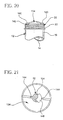
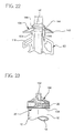
- the mixing blade 52 is preferably configured to include a number of protrusions or "wings" 144 which extend outwardly from the shaft 104 (see FIGS. 21 and 22).
- the wings 144 are aligned with the vanes 116 and are therefore positioned in the vane receiving slots 136 as shown in FIGS. 21 and 22. As such, rotation of the mixing blade 52, and therefore the wings 144, causes similar rotation of the blade wiping diaphragm 134.
- the wings 144 also function to retain the blade wiping diaphragm 134 on the mixing blade 52 prior to securement of the mixing head assembly 30 to the cartridge 16.
- the blade wiping diaphragm 134 is initially secured to the wings 144 of the mixing blade 52 prior to use of the mixing device 10.
- the powder bone cement component may be poured or otherwise advanced into the open end (i.e. the upper end 20) of the cartridge 16. Once the powder component has been poured into the open end of the cartridge 16, the mixing head assembly 30 is screwed onto the threads 22 of the upper end 20 of the cartridge 16.
- the outer peripheral edge 142 of the blade wiping diaphragm 134 is pressed or otherwise advanced under each of the snaps 140 in order to secure the diaphragm 134 to the cartridge 16.
- such positioning of the outer peripheral edge 142 of the blade wiping diaphragm 134 under the snaps 140 allows for retention of the blade wiping diaphragm 134 during subsequent removal of the mixing head assembly 30.
- the configuration of the mixing device 10 in which the blade wiping diaphragm 134 is rotated in concert with the mixing blade 52 reduces the number of vane receiving slots 136 that must be included in the construction of the blade wiping diaphragm 134. Specifically, since the wings 144 are retained in the slots 136, the vanes 116 (which are aligned with the wings 144) are likewise at all times aligned with the vane receiving slots 136. Hence, at any given time, the mixing blade 52 may be removed by pulling the vanes 116 of the blade 52 through the vane receiving slots 136. Such a reduction in the number of vane receiving slots 136 facilitates ease of manufacture of the blade wiping diaphragm 134.
- the shaft 104 of the mixing blade 52 also has an upper shoulder 146 and a lower shoulder 148 defined therein.
- the body of blade wiping diaphragm 134 is captured or otherwise positioned between the upper shoulder 146 and the lower shoulder 148.
- the upper shoulder 146 is greater in diameter than the lower shoulder 148.
- the upper shoulder prevents upward movement of the blade wiping diaphragm 134.
- the lower shoulder 148 is somewhat smaller in diameter and includes a number of rounded edges.
- the lower shoulder 148 supports the blade wiping diaphragm 134 in its desired position, but also allows for removal of the mixing blade 52 since the lower shoulder may be advance through the shaft receiving opening 138 of the blade wiping diaphragm 134 during removal of the blade 52.
- the mixing device 10 of the present invention may be utilized to deliver the mixed bone cement.
- the lower gear housing 38 is unscrewed from the cartridge 16 so that the mixing head assembly 30 may be removed from the cartridge 16. Thereafter, the delivery nozzle assembly 150 may be screwed onto the threads 22 of the upper end 20 of the cartridge 16.
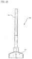
- the nozzle assembly 150 includes a nozzle 152 and an elongated tube 154.
- the length and/or diameter of the elongated tube 154 may be varied in order to fit the requirements of a given delivery application. Moreover, it should also be noted that in certain situations, it may be desirable to dispense (i.e. delivery) the mixed bone cement directly through the nozzle 152 without the use of the elongated tube 154.
- the lower end 24 of the cartridge 18 is unscrewed from the base 34 thereby separating the canister 12 from the base 34.
- Such removal of the base 34 also exposes a bottom surface 156 of the plunger 110 (see FIG. 7).
- the canister 12 may then be placed in the chamber of a delivery gun mechanism (not shown) much in the same way as a tube of caulk is placed in a household caulk gun.
- a contact member urges the plunger 110 in the general direction toward the nozzle assembly 150.
- Such movement of the plunger 110 forces the mixed bone cement within the mixing chamber 14 through the openings defined in the blade wiping diaphragm 134 (i.e. the vane receiving slots 136 and the shaft receiving opening 138) and then through the nozzle 152 and tube 154 of the nozzle assembly.
- the blade wiping diaphragm 134 i.e. the vane receiving slots 136 and the shaft receiving opening 138
- the bone cement mixing device 10 of the present invention is utilized to mix a liquid bone cement component with a powder bone cement component and thereafter deliver the mixed bone cement to a desired location during performance of a surgical procedure.
- the powder bone cement component is first placed in the mixing chamber 14 of the canister 12.
- a quantity of the powder bone cement component is poured or otherwise advanced into the open end of the cartridge 16 (i.e. the upper end 20 of the cartridge 16) and hence into the mixing chamber 14 of the canister 12.
- the canister 12 is preferably configured to accommodate (i.e. hold) at least 120 grams (e.g. three batches of 40 grams each) of powder bone cement.
- the mixing head 30 is screwed onto the upper end 20 of the cartridge 16.
- the threads 28 of the lower gear housing 38 are threadingly advanced onto the threads 22 of the upper end 20 of the cartridge 16 until the mixing head 30 is fully secured to the canister 12.
- the O-ring 158 is compressed thereby sealing the mixing head 30 to the canister 12 (see FIG. 19).
- the blade wiping diaphragm 134 (which is secured to the wings 144 of the mixing blade 52) is secured to the canister 12.
- the outer peripheral edge 142 of the blade wiping diaphragm 134 is pressed or otherwise advanced under the snaps 140 of the cartridge 16 thereby securing the diaphragm 134 to the cartridge 16.
- the liquid bone cement component (e.g. the monomer) may be advanced into the mixing chamber 12 and hence into contact with the powder bone cement component positioned therein.
- the port cap 128 is first removed from sealing engagement with the monomer delivery port 122 in order to permit fluid access to the mixing chamber 14 of the canister 12.
- the required quantity of liquid cement component may be introduced into the mixing chamber 14 of the canister 12 through the delivery port 122.
- an outlet coupling of a monomer delivery device (not shown) is first sealingly coupled to the monomer delivery port 122 of the mixing device 10.
- the liquid cement component e.g.
- the monomer contained in the monomer delivery device is introduced into the mixing chamber 14 via the fluid path which includes the delivery port 122, the tube 124, the fluid passageway 118 of the shaft 104, and the fluid orifices 120 of the shaft 104.
- the monomer is delivered at various locations throughout the depth of the powder component present in the mixing chamber 14.
- the liquid component e.g. the monomer
- the liquid component is delivered at locations throughout the height of the canister 12 thereby allowing the liquid to be interspersed throughout the depth of the powder component present in the mixing chamber 12.
- the monomer delivery port 122 is preferably embodied as a luer lock or other type of sealable component, and therefore "mated” with a similar type of outlet coupling on the monomer delivery device, the monomer is dispensed into the tube 124 (and hence the mixing chamber 14 of the canister 12) while preventing monomer vapours from escaping between the monomer delivery device and the mixing device 10 (e.g. between luer of the monomer delivery device and the luer lock of the mixing device 10).
- a vacuum source (not shown) is fluidly coupled to the vacuum port 132 of the lower gear housing 38 of the mixing head assembly 30 in order to draw air from the mixing chamber 14 of the mixing device 10.
- the introduction of a vacuum is useful during the introduction of the liquid cement component into the mixing chamber 14 since the presence of lower pressure within the chamber 14 tends to draw the liquid (i.e. the monomer) through the fluid orifices 120 of the shaft 104 and into the mixing chamber 14.
- the presence of the vacuum also removes vapours and the like from the mixing device 10 thereby further reducing the occasions in which such vapours escape from the device 10.
- the cap 128 is positioned back in sealing engagement within the delivery port 122 so as to prevent the escape of any vapours associated with the delivered monomer. Thereafter, the operator may commence to mix the liquid cement component and the powder cement component with one another.
- the gear train 46 of the present invention is configured such that the direction of rotation of the output pinion 48 (and hence the mixing blade 52) alternates (i.e. changes) despite rotation of the crank 40 (and hence the directional gear 54) in only a single direction.
- the idler gear 56 is engaged with the outer gear teeth 90 of the directional gear 54
- the output pinion 48 and hence the mixing blade 52 is rotated in a first direction.
- the idler gear disengages the outer gear teeth 90 and engages the inner gear teeth 86 of the directional gear 54
- the direction of travel of the output pinion 48 and hence the mixing blade 52 is reversed thereby creating alternating or reciprocating motion.
- the relatively large number of individual gear teeth associated with the outer gear teeth 90 creates a relatively large gear ratio with the idler gear 56 relative to the gear ratio created by inner gear teeth 86 and the idler gear 56, varying angular distances of travel and speeds of the mixing blade 52 are created.
- the mixing blade 52 is driven across 540° of rotation in a first direction and then reversed and driven across 135° of rotation in the opposite direction.
- the crank 40 when as the operator advances the crank 40 through such an entire revolution (i.e.
- the mixing blade 52 is driven three times as quickly in the first direction as it is when reversed and driven in the opposite direction.
- Such a reciprocating movement of the mixing blade 52 i.e. at varying angular distances and speeds) creates desirable "agitation" within the mixing chamber 14 of the canister 12 which increases the mix quality of the mixing device 10 by reducing, if not eliminating, the amount of the powder component bone cement which is not thoroughly mixed with the liquid component of the bone cement.
- the blade wiping diaphragm 134 is likewise rotated.
- the blade wiping diaphragm 134 is rotatable relative to the cartridge 16.
- the outer peripheral edge 142 of the blade wiping diaphragm 134 is positioned under the snaps 140 in order to secure the diaphragm 134 to the cartridge 16 in a manner which allows the diaphragm to rotate relative to the cartridge 16.
- the wings 144 of the mixing blade 52 are positioned in the vane receiving slots 136 thereby causing the blade wiping diaphragm 134 to be rotated in concert with the mixing blade 52.
- the mixing head assembly 30 is removed from the canister 12.
- the lower gear housing 38 is unscrewed from the cartridge 16 so that the mixing head assembly 30 may be removed from the cartridge 16 thereby allowing the delivery nozzle assembly 150 (see FIGS. 23 and 24) to be screwed onto the cartridge 16 in its place.
- the vanes 116 of the mixing blade 52 are advanced through the vane receiving slots 136 of the blade wiping diaphragm 134.
- the mixing blade 52 may be "pulled through" the openings (i.e. the vane receiving slots 136 and the shaft receiving opening 138) defined in the blade wiping diaphragm 134 without removing the blade wiping device.
- Such advancement of the vanes 116 through the vane receiving slots 136 wipes or otherwise removes any residual bone cement from the vanes 116 thereby preventing such residual bone cement from being wasted (i.e. removed from the mixing chamber 14, but not utilized in the surgical procedure).
- the mixing device 10 of the present invention may be utilized to deliver the mixed bone cement.
- the lower gear housing 38 is unscrewed from the cartridge 16 so that the mixing head assembly 30 may be removed from the cartridge 16.
- the delivery nozzle assembly 150 is screwed onto the threads 22 of the upper end 20 of the cartridge 16.
- the lower end 24 of the cartridge 18 is then unscrewed from the base 34 thereby separating the canister 12 from the base 34.
- such removal of the base 34 also exposes the bottom surface 156 of the plunger 110.
- the canister 12 may then be placed in the chamber of a delivery gun mechanism (not shown) much in the same way as a tube of caulk is placed in a household caulk gun.
- a contact member urges the plunger 110 in the general direction toward the nozzle assembly 150.
- Such movement of the plunger 110 forces the mixed bone cement within the mixing chamber 14 through the openings defined in the blade wiping diaphragm 134 (i.e. the vane receiving slots 136 and the shaft receiving opening 138) and then through the nozzle 152 and tube 154 of the nozzle assembly 150 thereby delivering the mixed bone cement to a desired location.
- bone cement mixing device 10 of the present invention provide numerous advantages over heretofore designed mixing apparatus.
- the alternating or reciprocating action of the mixing blade 52 enhances the quality of the mixed bone cement by reducing, if not eliminating, the amount of powder component which is not adequately mixed with the liquid component.
- such alternating or reciprocating action is advantageously generated by rotation of the crank 40 in only a single direction and at a single speed.
- the configuration of the gear train 46 eliminates the need for the operator to manually reverse the direction of the crank 40 and/or manually alter the speed at which the crank 40 is being rotated in order to produce the desired blade movement.
- the sealed relationship between the outlet coupling of the monomer delivery device and the delivery port 122 of the mixing device 10 provides for delivery and mixing of the bone cement without exposing the operator of the system to monomer vapours.
- the liquid component e.g. the monomer
- the liquid component is delivered at locations throughout the height of the canister 12 thereby allowing the liquid to be interspersed throughout the entire depth of the powder component present in the mixing chamber 12.
- this is a significant advantage over heretofore designed systems in which the monomer is poured or otherwise advanced through the lid of the mixing apparatus thereby only allowing the monomer to be introduced to the "top" of the powder within the mixing apparatus.
- the structure of the present invention also provide advantages over heretofore designed system having a delivery path through the mixing shaft of the system which have an opening only at the bottom end of the shaft (similar to a common drinking straw).
- the monomer only flows out of the bottom of the shaft and in some cases may be restricted by the plunger on which the lower end of the shaft rests.
Abstract
Description
- The present invention relates generally to a surgical assembly, and more particularly to an apparatus and method for mixing bone cement.
- It is necessary in many orthopaedic surgical procedures to employ a cement or grouting type agent, such as for attaching artificial joint implants, repairing or forming joints in bones, or other forms of orthopaedic work. The type of cement generally used for these purposes is a self-curing resin formed from the blending of a wide variety of liquid monomers or co-monomers with powdered polymers or copolymers to form a viscous admixture to be used as the grouting agent.
- The admixture of the powder and liquid components develops a quick setting material. As such, preparation of the cement usually occurs directly within the operating area just prior to use. In particular, a bone cement mixing apparatus is generally utilized to mix the powder and liquid components in the operating area. The resultant admixture is then removed from the mixing apparatus and placed in a cement delivery apparatus for subsequent use by the surgeon. Specifically, the bone cement must generally first be scooped or otherwise removed from the mixing apparatus and thereafter placed in a syringe-type delivery apparatus for use by the surgeon.
- The system described above for mixing and delivering bone cement has a number of drawbacks associated therewith. For example, monomer vapours are generated during the depositing of the monomer into the mixing apparatus and during the subsequent mixing of the monomer with the powder component of the bone cement. Such monomer vapours may be noxious and/or toxic. Because the bone cement is generally mixed in the operating room environment, it is important to prevent any monomer or its vapours from escaping the mixing apparatus. However, heretofore designed mixing apparatus have not included mechanisms for controlling the escape of such vapours.
- Moreover, heretofore designed mixing apparatus have been plagued with problems relating to the incomplete mixing of the liquid component and the powder component. Specifically, the powder component and liquid component are often inadequately mixed during operation of heretofore designed systems. Such a problem is further compounded by the fact that heretofore designed mixing vessels are not transparent thereby preventing the contents of the vessel (i.e. the bone cement) from being viewed by the operator of the mixing apparatus.
- In addition, the system described above also suffers from operational inefficiencies relating to the need to transfer the mixed bone cement from the mixing apparatus to the delivery apparatus. Specifically, the need to remove the mixed bone cement from one device (i.e. the mixing apparatus) and place it in a second device (i.e. the delivery device) creates an extra step in the process thereby increasing the time necessary to deliver the mixed bone cement. Moreover, a quantity of the bone cement is lost in the process since it is highly unlikely that all of the mixed cement is actually removed from the mixing apparatus and placed in the delivery apparatus.
- What is needed therefore is an apparatus and method for mixing a bone cement which overcomes one or more of the above-mentioned drawbacks. What is particularly needed is an apparatus and method for mixing bone cement which reduces, if not eliminates, exposure to vapours from the liquid bone cement component within the operating area. What is further needed is an apparatus and method for mixing bone cement which may also be utilized to delivery the mixed bone cement. What is moreover needed is an apparatus and method for mixing bone cement which reduces, or even eliminates, the occasions in which a portion of the powder cement component is not thoroughly mixed with the liquid cement component.
- In accordance with the concepts of the present invention, there is provided a bone cement mixing apparatus. The bone cement mixing apparatus includes a handle, and a canister defining a mixing chamber. The bone cement mixing apparatus further includes a mixing blade which is caused to rotate in response to movement of the handle, the mixing blade being positioned within the mixing chamber. The mixing blade includes a shaft and at least one vane supported by the shaft. Also, the shaft has defined therein (i) an inlet orifice, (ii) a plurality of outlet orifices, and (iii) a passageway which places the inlet orifice in fluid communication with each of the plurality of outlet orifices.
- Pursuant to another embodiment of the present invention, there is provided a method of mixing bone cement. The method includes the step of (i) placing a powder bone cement component within a canister, (ii) sealing the canister after the placing step, (iii) advancing a liquid bone cement component through a mixing blade located within the canister after the sealing step, and (iv) rotating the mixing blade after the liquid bone cement component is advanced through the mixing blade. The mixing blade includes (i) an inlet orifice, (ii) a plurality of outlet orifices, and (iii) a passageway which places the inlet orifice in fluid communication with each of the plurality of outlet orifices. In addition, the advancing step includes the step of advancing the liquid bone cement component (i) into the mixing blade through the inlet orifice, (ii) through the passageway, and (iii) out of the mixing blade through the plurality of outlet orifices.
- Yet according to another embodiment of the present invention, there is provided a bone cement mixing apparatus. The bone cement mixing apparatus includes a container defining a mixing chamber. Further, the bone cement mixing apparatus includes a mixing blade positioned within the mixing chamber, the mixing blade defining (i) an inlet orifice, (ii) a plurality of outlet orifices, and (iii) a passageway which places the inlet orifice in fluid communication with each of the plurality of outlet orifices.
- Yet according to another embodiment of the present invention, there is provided a bone cement mixing apparatus which includes a handle. The bone cement mixing apparatus further includes a first canister segment defining a first mixing chamber portion, and a second canister segment defining a second mixing chamber portion. Also, the bone cement mixing apparatus includes a mixing blade which is caused to rotate in response to movement of the handle. The mixing blade is located within both the first mixing chamber portion and the second mixing chamber portion. Moreover, the first canister segment includes a first coupling, and the second canister segment includes a second coupling. The first coupling cooperates with the second coupling so as to secure the first canister segment to the second canister segment.
- It is therefore an object of the present invention to provide a new and useful apparatus for mixing bone cement.
- It is moreover an object of the present invention to provide an improved apparatus for mixing bone cement.
- It is a further object of the present invention to provide a new and useful method for mixing bone cement.
- It is also an object of the present invention to provide an improved method for mixing bone cement.
- It is yet another object of the present invention to provide an apparatus and method for mixing bone cement which reduces, if not eliminates, exposure to vapours from the liquid bone cement component within the operating area.
- It is moreover an object of the present invention to provide an apparatus and method for mixing bone cement which may also be utilized to delivery the mixed bone cement.
- It is a further object of the present invention to provide an apparatus and method for mixing bone cement which reduces, or even eliminates, the occasions in which a portion of the powder cement component is not thoroughly mixed with the liquid cement component.
- The above and other objects, features, and advantages of the present invention will become apparent from the following description and the attached drawings.
- The present invention will now be described by way of example with reference to the accompanying drawings, in which:
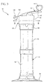
- FIG. 1 is a perspective view of bone cement mixing device which incorporates the features of the present invention therein;
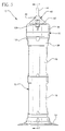
- FIGS. 2-5 are side elevational views of the mixing device of FIG. 1;
- FIG. 6 is an enlarged plan view of the mixing device of FIG. 1;
- FIG. 7 is a cross sectional view of the mixing device of FIG. 1, taken along the line 7-7 of FIG. 5, as viewed in the direction of the arrows;
- FIG. 8 is a cross sectional view taken along the line 8-8 of FIG. 3, as viewed in the direction of the arrows;
- FIG. 9 is a cross sectional view taken along the line 9-9 of FIG. 2, as viewed in the direction of the arrows;
- FIG. 10 is a cross sectional view taken along the line 10-10 of FIG. 4, as viewed in the direction of the arrows;
- FIG. 11 is a cross sectional view taken along the line 11-1 of FIG. 4, as viewed in the direction of the arrows;
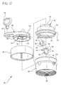
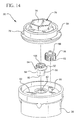
- FIGS. 12-14 are exploded perspective views of the mixing head assembly of the mixing device of FIG. 1;
- FIGS. 15 and 16 are bottom perspective views of the gear train of the mixing head assembly of FIGS. 12-14;
- FIG. 17 is a bottom perspective view of the directional gear of the gear train of FIGS. 15 and 16;
- FIGS. 18-20 are fragmentary perspective views which show the blade wiping diaphragm of the mixing device of FIG. 1;
- FIG. 21 is fragmentary plan view of the blade wiping diaphragm of FIGS. 18-20 and the mixing blade of FIG. 7;
- FIG. 22 is a fragmentary side elevational view of the blade wiping diaphragm of FIGS. 18-20 and the mixing blade of FIG. 7;
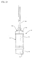
- FIGS. 23 and 24 are fragmentary perspective views of the mixing device of FIG. 1 with the cement delivery nozzle secured thereto; and
- FIG. 25 is an enlarged view of the cement delivery nozzle of FIGS. 23 and 24.
-
- Referring to the drawings, FIGS. 1-7 show a bone
cement mixing device 10 which can receive a quantity of a powder bone cement component and a liquid bone cement component (e.g. a monomer) and thereafter mix the powder component and liquid component together. The bonecement mixing device 10 is also operable as a bone cement delivery device thereby eliminating the need to utilize a separate delivery device. - The mixing
device 10 includes acanister 12 having a mixingchamber 14 defined therein. Thecanister 12 is preferably embodied as a pair of identical cylindrically-shapedcartridges cartridges device 10 while also reducing the number of different components which are utilized in the design thereof. - Each of the
cartridges cartridges - Moreover, the
cartridges cartridges device 10 of the present invention overcomes this limitation by being configured to mix all three of the batches simultaneously. - The
upper end 20 of each of thecartridges threads 22 defined therein, whereas thelower end 24 of each of thecartridges threads 26 defined therein. Thethreads cartridges 16, 18), or may be engaged to a number of other components. In particular, as shown in FIG. 7, thethreads 22 of theupper end 20 of thecartridge 16 are threadingly engaged with a number ofthreads 28 associated with a mixinghead assembly 30. Thethreads 26 of thelower end 24 of thecanister 18, on the other hand, are threadingly engaged with a number ofthreads 32 defined in abase 34. It should be appreciated that sealing members such as O-rings 158 (see FIGS. 7, 9, and 23) are preferably utilized at each threaded coupling (i.e. between thecartridges cartridge 16 and the mixinghead assembly 30, and between thecartridge 18 and the base 34). - As shown in FIGS. 1, 7, and 9, the mixing
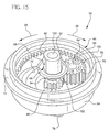
head assembly 30 includes anupper gear housing 36 and alower gear housing 38. Theupper gear housing 36 is press fit or otherwise secured to thelower gear housing 38. The mixinghead assembly 30 also includes a crank 40 which is rotatably secured to theupper gear housing 36. Thecrank 40 includes anelongated arm 42 having aknob 44 rotatably secured to an end thereof. As will be discussed below in greater detail, theupper gear housing 36 and thelower gear housing 38 cooperate to house agear train 46 which is driven by rotation of thecrank 40. Specifically, thegear train 46 includes anoutput pinion 48 which is rotatably coupled to thelower gear housing 38. Theoutput pinion 48 includes a downwardly extendingcoupling portion 50 which extends through anaperture 51 defined in the lower gear housing 38 (see also FIG. 13). Thecoupling portion 50 of theoutput pinion 48 is non-rotatably secured to anupper end 106 of amixing blade 52. In particular, as shown in FIGS. 9 and 12, thecoupling portion 50 of theoutput pinion 48 includes a number ofbarbs 58 which are received into a corresponding number of slots 60 (see FIGS. 7 and 9) defined in acoupling portion 108 of themixing blade 52. Hence, rotation of theoutput pinion 48 causes similar rotation (i.e. in the same direction and at the same angular velocity) of themixing blade 52. - Referring now to FIGS. 12-17, the mixing
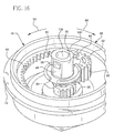
head assembly 30 is shown in greater detail. In addition to the crank 40 and thegear housings head assembly 30 also includes adirectional gear 54, anidler gear 56, and theoutput pinion 48. As shown in FIGS. 12 and 13, thedirectional gear 54, theidler gear 56, and theoutput pinion 48 are housed within the housing defined by theupper gear housing 36 and thelower gear housing 38. Specifically, theoutput pinion 48 has ashoulder 60 defined therein. Upon insertion of thecoupling portion 50 of theoutput pinion 48 into theaperture 51 defined in thelower gear housing 38, theshoulder 60 of theoutput pinion 48 contacts a retainingsurface 62 of the gear housing 38 (see FIG. 13) thereby retaining theoutput opinion 48 while also allowing it to rotate relative to thegear housing 38. - The
idler gear 56 has anaperture 64 defined therein (see FIG. 12) which is received around a post 66 (see FIGS. 13 and 14) defined in thelower gear housing 38 thereby rotatably securing theidler gear 56 to thelower gear housing 38. The other end of theidler gear 56 has apost 68 extending therefrom which is received into aslot 70 defined in thebody 72 of the directional gear 54 (see FIGS. 10 and 17). Thepost 68 is captured by or is otherwise retained within theslot 70 during rotation of thedirectional gear 54. - The
directional gear 54 is non-rotatably secured to the crank 40 by use of a hexagonally-shapedcoupling mechanism 74. In particular, thecrank 40 has a hexagonally-shapedmember 76 extending downwardly therefrom, whereas thebody 72 of thedirectional gear 54 has a slightly larger hexagonally-shapedmember 78 extending upwardly therefrom. During assembly of the mixinghead assembly 30, ashoulder 80 of the crank is positioned in contact which abearing surface 82 defined on the upper surface of the upper gear housing 36 (see FIG. 13) thereby allowing the hexagonally-shapedmember 76 of thecrank 40 to extend through ahousing opening 84 defined in theupper gear housing 36. When positioned in such a manner, the hexagonally-shapedmember 76 of thecrank 40 may be press fit or otherwise received into the hexagonally-shapedmember 78 of thedirectional gear 54 which is positioned within the upper gear housing 36 (see FIG. 11). When secured in such a manner, rotation of the crank 40 relative to theupper gear housing 36 causes similar rotation of thedirectional gear 54 relative to theupper gear housing 36. Note that thedirectional gear 54 is caused to rotate about a central axis CA as shown in FIG 17. - The
idler gear 56 meshes with both thedirectional gear 54 and theoutput pinion 48. In particular, as shown in FIG. 17, thedirectional gear 54 includes a first number ofgear teeth 86 defined in thebody 72 thereof. Thegear teeth 86 are positioned around a portion of the periphery of anaperture 88 which defines the axis of rotation of thedirectional gear 54. Thedirectional gear 54 also includes a second number ofgear teeth 90 defined in thebody 72 thereof. As can be seen in FIG. 17, thegear teeth 90 are spaced radially outwardly from thegear teeth 86. As will be discussed below in greater detail, thegear teeth 86 and thegear teeth 90 selectively meshes with theidler gear 56 so as to selectively drive the output pinion 48 (and hence the mixing blade 52) at varying velocities and directions of rotation. - Note that the central axis CA lies in a plane P which divides the
directional gear 54 into a first directional gear side and a second directional gear side (see e.g. FIG. 17). Moreover, thedirectional gear 54 is configured so that (i) thegear teeth 86 are positioned entirely on the first input gear side, and (ii) thegear teeth 90 are positioned entirely on the second input gear side as shown in FIG. 17. - As shown in FIGS. 12-14, 15, and 16, the
idler gear 56 has a number ofgear teeth 92 defined therein, whereas theoutput pinion 48 has a number ofgear teeth 94 defined therein. Thegear teeth 92 of theidler gear 56 meshes with thegear teeth 94 of theoutput pinion 48. As such, rotation of theidler gear 56 in a given direction causes rotation of theoutput pinion 48 in the opposite direction. For example, clockwise rotation of theidler gear 56 causes counterclockwise rotation of theoutput pinion 48, and vice versa. - As alluded to above, the
gear teeth 92 of theidler gear 56 are engaged by either theinner gear teeth 86 or theouter gear teeth 90 of thedirectional gear 54 during rotation of thedirectional gear 54. Specifically, during rotation of thedirectional gear 54 in the counterclockwise direction (as viewed from the bottom perspective view of FIGS. 15-17 and designated by the arrow 96), theidler gear 56 is initially engaged by theouter gear teeth 90 of thedirectional gear 54 thereby causing theidler gear 56 to likewise be rotated in the counterclockwise direction (as indicated by the arrow 96). Rotation of theidler gear 56 in the counterclockwise direction causes rotation of the output pinion 48 (and hence the mixing blade 52) in the opposite direction (i.e. in a clockwise rotation as viewed from the bottom perspective view of FIGS. 15-17 and designated by the arrow 98). - Continued rotation of the crank 40 (and hence the directional gear 54) in the counterclockwise direction (as viewed from the bottom perspective view of FIGS. 15-17 and indicated by the arrow 96) causes the
last gear tooth 100 of theouter gear teeth 90 to be rotated out of engagement with theidler gear 56 and afirst tooth 102 of theinner gear teeth 86 to be rotated into meshing engagement with theidler gear 56. It should be appreciated that a small radial gap may be provided between thelast gear tooth 100 of theouter gear teeth 90 and thefirst gear tooth 102 of theinner gear teeth 86 in order to prevent theidler gear 56 from being simultaneously engaged by both sets ofgear teeth - In any event, as the
inner gear teeth 94 mesh with theidler gear 56, the direction of travel of theidler gear 56 is changed. Specifically, when thedirectional gear 54 is rotated in the counterclockwise direction (as viewed from the bottom perspective view of FIGS. 15-17 and indicated by the arrow 96), meshing engagement with theinner gear teeth 94 causes theidler gear 56 to be rotated in the opposite direction (i.e. the clockwise direction as viewed from the bottom perspective view of FIGS. 15-17 and indicated by the arrow 94). Such clockwise rotation of theidler gear 56 causes the output pinion 48 (and hence the mixing blade 52) to be rotated in the opposite direction (i.e. the counterclockwise direction as viewed from the bottom perspective view of FIGS. 15-17 and indicated by the arrow 96). - It should be appreciated that if the
crank 40 is rotated in the opposite direction (i.e. so as to cause rotation of thedirectional gear 54 in the clockwise direction as viewed in FIGS. 15-17 and indicated by arrow 98), theidler gear 56 and theoutput pinion 48 are rotated in the respective opposite directions to that as described above. In particular, rotation of thedirectional gear 54 in the clockwise direction (i.e. in the direction ofarrow 98 of FIGS. 15-17) causes (1) clockwise rotation of theidler gear 56, and (2) counterclockwise rotation of the output pinion 48 (and hence the mixing blade 52) when theidler gear 56 is meshes with theouter gear teeth 90. Similarly, rotation of thedirectional gear 54 in the clockwise direction (i.e. in the direction ofarrow 98 of FIGS. 15-17) causes (1) counterclockwise rotation of theidler gear 56, and (2) clockwise rotation of the output pinion 48 (and hence the mixing blade 52) when theidler gear 56 is meshed with theinner gear teeth 86. - Hence, as described above, the
gear train 46 of the present invention is configured such that the direction of rotation of theoutput pinion 48 changes despite rotation of thecrank 40 in only a single direction. Specifically, as theidler gear 56 is engaged with theouter gear teeth 90, theoutput pinion 48 and hence themixing blade 52 is rotated in a first direction. However, as theidler gear 56 disengages theouter gear teeth 90 and engages theinner gear teeth 86, the direction of travel of theoutput pinion 48 and hence themixing blade 52 is reversed thereby creating alternating or reciprocating motion. - Moreover, since the relatively large number of individual gear teeth associated with the
outer gear teeth 90 creates a relatively large gear ratio with theidler gear 56 relative to the gear ratio created byinner gear teeth 86 and theidler gear 56, varying angular distances of travel and speeds of themixing blade 52 are created. Specifically, the relatively high gear ratio created by theouter gear teeth 90 causes theoutput pinion 48 to be driven across a greater angular distance when theidler gear 56 is engaged with theouter gear teeth 90 relative to the angular distance across which theoutput pinion 48 is driven when theidler gear 56 is engaged with theinner gear teeth 86. In one exemplary embodiment, the output pinion 48 (and hence the mixing blade 52) is driven across 540° of rotation when theidler gear 56 is engaged with theouter drive teeth 90, whereas the output pinion (and hence the mixing blade 52) is only advanced across 135° of rotation (in the opposite direction) when theidler gear 56 is engaged with theinner drive teeth 86. In other words, in such an exemplary embodiment, when an operator advances the crank 40 through an entire revolution (i.e. 360° of rotation), themixing blade 52 is driven across 540° of rotation in a first direction and then reversed and driven across 135° of rotation in the opposite direction. - Moreover, the relatively high gear ratio created by the
outer gear teeth 90 also causes theoutput pinion 48 to be driven at a greater angular velocity when theidler gear 56 is engaged with theouter gear teeth 90 relative to the angular velocity at which theoutput pinion 48 is driven when theidler gear 56 is engaged with theinner gear teeth 86. In one exemplary embodiment, when theidler gear 56 is engaged with theouter drive teeth 90, the output pinion 48 (and hence the mixing blade 52) is driven at a velocity which is approximately three times greater than the velocity at which the output pinion 48 (and hence the mixing blade 52) is driven when theidler gear 56 is engaged with theinner drive teeth 86. In other words, in such an exemplary embodiment, when an operator advances the crank 40 through an entire revolution (i.e. 360° of rotation), themixing blade 52 is driven three times as quickly in the first direction as it is when reversed and driven in the opposite direction. - It should be appreciated that the configuration of the
directional gear 54 described herein is exemplary in nature and may be altered to fit the requirements of a given design of the mixingdevice 10. In particular, it should be noted that the number of teeth included in thegear teeth gear teeth mixing blade 52 is driven during rotation of thecrank 40 by the operator. - It should also be appreciated that the drive characteristics of the mixing
head assembly 30 which are described above provide numerous advantages to themixing device 10 of the present invention relative to heretofore designed mixing devices. For example, the reciprocating movement of the mixing blade 52 (i.e. at varying angular distances and speeds) creates desirable "agitation" within the mixingchamber 14 of thecanister 12. Such agitation increases the mix quality of the mixingdevice 10 by reducing, if not eliminating, the amount of the powder component which is not thoroughly mixed with the liquid component. - Referring now to FIG. 7, the
mixing blade 52 will be described in greater detail. Themixing blade 52 includes an elongatedcentral shaft 104 having anupper end 106 which includes thecoupling portion 108 for securing theshaft 104 of theblade 52 to thecoupling portion 50 of theoutput pinion 48. Theshaft 104 also has alower end 108 which extends downwardly and into contact with aplunger 110. Theplunger 110 is made from a plastic material such as polyethylene. Theplunger 110 includes arecess 112 which receives atip 114 of theshaft 104 thereby providing mechanical support for theshaft 104 during rotation thereof. - A number of blades or
vanes 116 extend outwardly from theshaft 104 as shown in FIG. 7. Themixing blade 52 may be configured as a "two-dimensional" (i.e. flat) blade, or alternatively, may be configured as a "three dimensional" blade. Specifically, although thevanes 116 may be configured to extend outwardly in only two directions from theshaft 104, thevanes 116 of themixing blade 52 may also be configured to extend outwardly from theshaft 104 in three directions. In such a three dimensional configuration, themixing blade 52 is not substantially flat when positioned on a relatively flat surface, but rather extends in a number of different directions (including upwardly) from the flat surface. - Moreover, as shown in FIG. 7, the
vanes 116 are oriented in somewhat of a helical configuration around theshaft 104. Such a configuration provides numerous advantages to themixing device 10 of the present invention. For example, the helical configuration of themixing blade 52 generates a desirable amount of "turbulence" within the mixingchamber 14 of thecanister 12 thereby increasing the mixing efficiency of the mixingdevice 10. - The
shaft 104 of themixing blade 52 has an elongatedfluid passageway 118 defined therein. Thefluid passageway 118 extends from theupper end 106 of theshaft 104 to thelower end 108 of theshaft 104. Thefluid passageway 118 is placed in fluid communication with the mixingchamber 14 of thecanister 12 via a number offluid orifices 120 defined in theshaft 104. While seven (7)fluid orifices 120 are shown defined in theshaft 104, it should be appreciated that there may be more than seven (7) fluid orifices defined in the shaft 104 (e.g. nine or ten fluid orifices). Alternatively, there may be less than seven (7) fluid orifices defined in the shaft 104 (e.g. two or three fluid orifices). Thefluid passageway 118 and thefluid orifices 120 allow for the introduction of the liquid cement component (e.g. the monomer) without exposing the operator to any vapours or fumes from therefrom. In particular, as shown in FIG. 7, thecrank 40 has amonomer delivery port 122 defined therein (see also FIG. 12). A tube 124 (see FIG. 7) is press fit into the lower end of thedelivery port 122 and extends downwardly through theaperture 88 defined in thedirectional gear 54 and asimilar aperture 126 defined in the output pinion 48 (see FIGS. 9, 12, 15, and 16). The lower end of thetube 124 is press fit or otherwise positioned in thecoupling portion 108 of themixing blade 52 so as to be in fluid communication with thefluid passageway 118 defined in theshaft 104. - Hence, a quantity of liquid cement component may be introduced into the mixing
chamber 14 of thecanister 12 through thedelivery port 122. Specifically, the liquid cement component (e.g. the monomer) may be introduced into the mixingchamber 14 via a fluid path which includes thedelivery port 122, thetube 124, thefluid passageway 118 of theshaft 104, and thefluid orifices 120 of theshaft 104. In such a manner, the monomer may be delivered at various locations throughout the depth of the powder component which is present in the mixingchamber 14. In particular, since thefluid orifices 120 are provided at a number of different locations along the length of theshaft 104, the liquid component (e.g. the monomer) is delivered at locations throughout the height of thecanister 12 thereby allowing the liquid to be interspersed throughout the powder component present in the mixingchamber 12. This is a significant advantage over heretofore designed systems in which the monomer is poured or otherwise advanced through the lid of the mixing apparatus thereby only allowing the monomer to be introduced to the "top" of the powder within the mixing apparatus. Moreover, the structure of the present invention also provide advantages over heretofore designed systems having a delivery path through the mixing shaft of the system which have an opening only at the bottom end of the shaft (similar to a common drinking straw). In such a configuration, the monomer flows only out of the bottom of the shaft and in some cases may be restricted by the plunger on which the lower end of the shaft rests. - It should be appreciated that the
monomer delivery port 122 may be embodied to include a luer lock that is configured such that a luer or similar spout from a monomer delivery device (not shown) may be extended into sealing engagement therewith. The use of such a luer lock allows monomer to be dispensed into tube 124 (and hence the mixingchamber 14 of the canister 12) while preventing monomer vapours from escaping between the monomer delivery device and the mixing device 10 (i.e. between luer of the delivery device and the luer lock of the mixing device). - It should be appreciated that such a luer lock may be configured to facilitate a "slip fit" type of sealing arrangement, or, alternately, may be configured to facilitate a threaded coupling with the corresponding mechanism of the monomer delivery device. Moreover, a combination coupling mechanism may be utilized which facilitates mating with both threaded and non-threaded couplings.
- A
cap 128 is provided to selectively seal thedelivery port 122. Specifically, thecap 128 may be sealing received into thedelivery port 122 in order to seal thedelivery port 122 in a manner which prevents vapours or the like from escaping therefrom. Atether 130 extends between thecrank 40 and thecap 128 in order to movably secure thecap 128 to thecrank 40. - As alluded to above, the
cap 128 is used to sealdelivery port 122 after the monomer has been dispensed into mixingchamber 14 during the mixing process. Thecap 128 is shown in a disengaged position in FIG. 7 in anticipation of the coupling of the monomer delivery device (not shown) with thedelivery port 122 for the purpose of delivering monomer from the monomer delivery device into the mixingchamber 14. It will be appreciated that a variety of luer locks and luer lock caps may be used in the present invention. For example, a self-closing luer lock may be used thereby eliminating the need forluer cap 128 or, as described above, a threaded luer lock may be used to screw thecap 128 onto the body of thecrank 40. In another embodiment, the monomer delivery device itself may be used as a seal for the luer lock. In yet another embodiment, theluer cap 128 may be replaced with a paper-backed piece of re-sealable tape or the like which may be removed to allow for mating with the monomer delivery device, and then replaced when the monomer delivery device is detached. - Referring now to FIG. 9, the
lower gear housing 38 has avacuum port 132 defined therein (see also FIG. 1). A vacuum source (not shown) may be fluidly coupled to thevacuum port 132 in order to draw air from the mixingchamber 14 of the mixingdevice 10. The introduction of a vacuum is useful during the introduction of the liquid cement component into the mixingchamber 14 since the presence of lower pressure within thechamber 14 tends to draw the liquid (i.e. the monomer) through thefluid orifices 120 of theshaft 104 and into the mixingchamber 14. Moreover, the presence of the vacuum also removes vapours and the like from the mixingdevice 10 thereby further reducing the occasions in which such vapours escape from thedevice 10. - As shown in FIG. 7, 9, 18-22, the mixing
device 10 also includes a blade wiping member ordiaphragm 134. Theblade wiping diaphragm 134 is preferably constructed of an elastomeric material. Theblade wiping diaphragm 134 has a number ofvane receiving slots 136 and ashaft receiving opening 138 defined therein. As will now be described in greater detail, theblade wiping diaphragm 134 is provided to "wipe" or otherwise remove residual bone cement for themixing blade 52 during removal thereof from the mixingchamber 14. As such, theblade wiping diaphragm 134 may be configured to include any number, size, or shape ofvane receiving slots 136 in order to accommodate a given design of amixing blade 52. - Once the liquid bone cement component (e.g. the monomer) and the powder bone cement component have been thoroughly mixed with one another, the
lower gear housing 38 is unscrewed from thecartridge 16 so that the mixinghead assembly 30 may be removed from thecartridge 16 thereby allowing a delivery nozzle assembly 150 (see FIGS. 23 and 24) to be screwed onto thecartridge 16 in its place. During such removal of the mixinghead assembly 30, as shown in FIG. 19, thevanes 116 of themixing blade 52 are advanced through thevane receiving slots 136 of theblade wiping diaphragm 134. Such advancement of thevanes 116 through thevane receiving slots 136 wipes or otherwise removes any residual bone cement from thevanes 116 thereby preventing such residual bone cement from being wasted (i.e. removed from the mixingchamber 14, but not utilized in the surgical procedure). - In order to provide for proper alignment of the
vanes 116 of themixing blade 52 with thevane receiving slots 136, theblade wiping diaphragm 134 is rotatably secured to thecartridge 16. In particular, as show in FIG. 18, thecartridge 16 includes a number of retaining members or snaps 140. An outerperipheral edge 142 of theblade wiping diaphragm 134 is positioned under thesnaps 140 in order to secure thediaphragm 134 to thecartridge 16 during securement of the mixinghead assembly 30 to thecartridge 16. Moreover, themixing blade 52 is preferably configured to include a number of protrusions or "wings" 144 which extend outwardly from the shaft 104 (see FIGS. 21 and 22). Thewings 144 are aligned with thevanes 116 and are therefore positioned in thevane receiving slots 136 as shown in FIGS. 21 and 22. As such, rotation of themixing blade 52, and therefore thewings 144, causes similar rotation of theblade wiping diaphragm 134. - Moreover, the
wings 144 also function to retain theblade wiping diaphragm 134 on themixing blade 52 prior to securement of the mixinghead assembly 30 to thecartridge 16. In particular, theblade wiping diaphragm 134 is initially secured to thewings 144 of themixing blade 52 prior to use of the mixingdevice 10. In such a manner, as shall be discussed below in greater detail, the powder bone cement component may be poured or otherwise advanced into the open end (i.e. the upper end 20) of thecartridge 16. Once the powder component has been poured into the open end of thecartridge 16, the mixinghead assembly 30 is screwed onto thethreads 22 of theupper end 20 of thecartridge 16. As the mixing head is screwed onto theupper end 20 of thecartridge 16, the outerperipheral edge 142 of theblade wiping diaphragm 134 is pressed or otherwise advanced under each of thesnaps 140 in order to secure thediaphragm 134 to thecartridge 16. As shall be discussed below in greater detail, such positioning of the outerperipheral edge 142 of theblade wiping diaphragm 134 under thesnaps 140 allows for retention of theblade wiping diaphragm 134 during subsequent removal of the mixinghead assembly 30. - It should be appreciated that the configuration of the mixing
device 10 in which theblade wiping diaphragm 134 is rotated in concert with themixing blade 52 reduces the number ofvane receiving slots 136 that must be included in the construction of theblade wiping diaphragm 134. Specifically, since thewings 144 are retained in theslots 136, the vanes 116 (which are aligned with the wings 144) are likewise at all times aligned with thevane receiving slots 136. Hence, at any given time, themixing blade 52 may be removed by pulling thevanes 116 of theblade 52 through thevane receiving slots 136. Such a reduction in the number ofvane receiving slots 136 facilitates ease of manufacture of theblade wiping diaphragm 134. - As shown in FIG. 22, the
shaft 104 of themixing blade 52 also has anupper shoulder 146 and alower shoulder 148 defined therein. As shown in FIG. 22, the body ofblade wiping diaphragm 134 is captured or otherwise positioned between theupper shoulder 146 and thelower shoulder 148. Theupper shoulder 146 is greater in diameter than thelower shoulder 148. The upper shoulder prevents upward movement of theblade wiping diaphragm 134. Thelower shoulder 148, on the other hand, is somewhat smaller in diameter and includes a number of rounded edges. In such a manner, thelower shoulder 148 supports theblade wiping diaphragm 134 in its desired position, but also allows for removal of themixing blade 52 since the lower shoulder may be advance through theshaft receiving opening 138 of theblade wiping diaphragm 134 during removal of theblade 52. - As alluded to above, once the liquid cement component and the powder cement component have been thoroughly mixed, the mixing
device 10 of the present invention may be utilized to deliver the mixed bone cement. In particular, as shown in FIGS. 23-25, once the liquid bone cement component (e.g. the monomer) and the powder bone cement component have been thoroughly mixed with one another, thelower gear housing 38 is unscrewed from thecartridge 16 so that the mixinghead assembly 30 may be removed from thecartridge 16. Thereafter, thedelivery nozzle assembly 150 may be screwed onto thethreads 22 of theupper end 20 of thecartridge 16. Thenozzle assembly 150 includes anozzle 152 and anelongated tube 154. It should be appreciated that the length and/or diameter of theelongated tube 154 may be varied in order to fit the requirements of a given delivery application. Moreover, it should also be noted that in certain situations, it may be desirable to dispense (i.e. delivery) the mixed bone cement directly through thenozzle 152 without the use of theelongated tube 154. - In any event, once the
nozzle assembly 150 has been secured to thecanister 12, thelower end 24 of thecartridge 18 is unscrewed from the base 34 thereby separating thecanister 12 from thebase 34. Such removal of the base 34 also exposes abottom surface 156 of the plunger 110 (see FIG. 7). Thecanister 12 may then be placed in the chamber of a delivery gun mechanism (not shown) much in the same way as a tube of caulk is placed in a household caulk gun. As the operator squeezes the trigger (not shown) or otherwise actuates the gun mechanism, a contact member (not shown) urges theplunger 110 in the general direction toward thenozzle assembly 150. Such movement of theplunger 110 forces the mixed bone cement within the mixingchamber 14 through the openings defined in the blade wiping diaphragm 134 (i.e. thevane receiving slots 136 and the shaft receiving opening 138) and then through thenozzle 152 andtube 154 of the nozzle assembly. - In operation, the bone
cement mixing device 10 of the present invention is utilized to mix a liquid bone cement component with a powder bone cement component and thereafter deliver the mixed bone cement to a desired location during performance of a surgical procedure. In order to do so, the powder bone cement component is first placed in the mixingchamber 14 of thecanister 12. In particular, with the mixinghead assembly 30 removed from thecanister 12, a quantity of the powder bone cement component is poured or otherwise advanced into the open end of the cartridge 16 (i.e. theupper end 20 of the cartridge 16) and hence into the mixingchamber 14 of thecanister 12. As discussed above, thecanister 12 is preferably configured to accommodate (i.e. hold) at least 120 grams (e.g. three batches of 40 grams each) of powder bone cement. - Once the powder bone cement component has been placed in the
canister 12, the mixinghead 30 is screwed onto theupper end 20 of thecartridge 16. In particular, as shown in FIG. 7, thethreads 28 of thelower gear housing 38 are threadingly advanced onto thethreads 22 of theupper end 20 of thecartridge 16 until the mixinghead 30 is fully secured to thecanister 12. As discussed above, as the mixing head assembly is screwed onto the upper end of thecartridge 16, the O-ring 158 is compressed thereby sealing the mixinghead 30 to the canister 12 (see FIG. 19). - Moreover, during such attachment of the mixing
head 30 to thecanister 12, the blade wiping diaphragm 134 (which is secured to thewings 144 of the mixing blade 52) is secured to thecanister 12. In particular, as the mixinghead assembly 30 is screwed onto thecanister 12, the outerperipheral edge 142 of theblade wiping diaphragm 134 is pressed or otherwise advanced under thesnaps 140 of thecartridge 16 thereby securing thediaphragm 134 to thecartridge 16. - Once the mixing
head assembly 30 is sealingly secured to thecanister 12 in such a manner, the liquid bone cement component (e.g. the monomer) may be advanced into the mixingchamber 12 and hence into contact with the powder bone cement component positioned therein. In particular, as shown in FIG. 7, theport cap 128 is first removed from sealing engagement with themonomer delivery port 122 in order to permit fluid access to the mixingchamber 14 of thecanister 12. Thereafter, the required quantity of liquid cement component may be introduced into the mixingchamber 14 of thecanister 12 through thedelivery port 122. Specifically, an outlet coupling of a monomer delivery device (not shown) is first sealingly coupled to themonomer delivery port 122 of the mixingdevice 10. Thereafter, the liquid cement component (e.g. the monomer) contained in the monomer delivery device is introduced into the mixingchamber 14 via the fluid path which includes thedelivery port 122, thetube 124, thefluid passageway 118 of theshaft 104, and thefluid orifices 120 of theshaft 104. In such a manner, the monomer is delivered at various locations throughout the depth of the powder component present in the mixingchamber 14. In particular, sincefluid orifices 120 are provided at a number of different locations along the length of theshaft 104, the liquid component (e.g. the monomer) is delivered at locations throughout the height of thecanister 12 thereby allowing the liquid to be interspersed throughout the depth of the powder component present in the mixingchamber 12. - It should be appreciated that since the
monomer delivery port 122 is preferably embodied as a luer lock or other type of sealable component, and therefore "mated" with a similar type of outlet coupling on the monomer delivery device, the monomer is dispensed into the tube 124 (and hence the mixingchamber 14 of the canister 12) while preventing monomer vapours from escaping between the monomer delivery device and the mixing device 10 (e.g. between luer of the monomer delivery device and the luer lock of the mixing device 10). - It should be appreciated that, as described above, it may be desirable to introduce the monomer into the mixing
chamber 14 of thecanister 12 in the presence of a vacuum withinchamber 14. In such a case, a vacuum source (not shown) is fluidly coupled to thevacuum port 132 of thelower gear housing 38 of the mixinghead assembly 30 in order to draw air from the mixingchamber 14 of the mixingdevice 10. The introduction of a vacuum is useful during the introduction of the liquid cement component into the mixingchamber 14 since the presence of lower pressure within thechamber 14 tends to draw the liquid (i.e. the monomer) through thefluid orifices 120 of theshaft 104 and into the mixingchamber 14. Moreover, the presence of the vacuum also removes vapours and the like from the mixingdevice 10 thereby further reducing the occasions in which such vapours escape from thedevice 10. However, in certain applications, it may be desirable to introduce the liquid monomer into the mixingchamber 14 without the presence of a vacuum within thecanister 12. - In any event, after the monomer has been dispensed into mixing
chamber 14 in the manner described above, thecap 128 is positioned back in sealing engagement within thedelivery port 122 so as to prevent the escape of any vapours associated with the delivered monomer. Thereafter, the operator may commence to mix the liquid cement component and the powder cement component with one another. - Specifically, the operator grips the outer surface of the
canister 12 with one hand while gripping theknob 44 of thecrank 40 with the other hand. The operator then rotates thecrank 40 in either a clockwise or counterclockwise direction. Such rotation of thecrank 40 drives thegear train 46 of the mixinghead assembly 30. As described in detail above, thegear train 46 of the present invention is configured such that the direction of rotation of the output pinion 48 (and hence the mixing blade 52) alternates (i.e. changes) despite rotation of the crank 40 (and hence the directional gear 54) in only a single direction. Specifically, as shown in FIGS. 12-17, as theidler gear 56 is engaged with theouter gear teeth 90 of thedirectional gear 54, theoutput pinion 48 and hence themixing blade 52 is rotated in a first direction. However, as the idler gear disengages theouter gear teeth 90 and engages theinner gear teeth 86 of thedirectional gear 54, the direction of travel of theoutput pinion 48 and hence themixing blade 52 is reversed thereby creating alternating or reciprocating motion. - Moreover, as described above in greater detail, since the relatively large number of individual gear teeth associated with the
outer gear teeth 90 creates a relatively large gear ratio with theidler gear 56 relative to the gear ratio created byinner gear teeth 86 and theidler gear 56, varying angular distances of travel and speeds of themixing blade 52 are created. For example, in the case of the exemplary embodiment described herein, as the operator advances the crank 40 through an entire revolution (i.e. 360° of rotation), themixing blade 52 is driven across 540° of rotation in a first direction and then reversed and driven across 135° of rotation in the opposite direction. Moreover, in such an exemplary embodiment, when as the operator advances the crank 40 through such an entire revolution (i.e. 360° of rotation), themixing blade 52 is driven three times as quickly in the first direction as it is when reversed and driven in the opposite direction. Such a reciprocating movement of the mixing blade 52 (i.e. at varying angular distances and speeds) creates desirable "agitation" within the mixingchamber 14 of thecanister 12 which increases the mix quality of the mixingdevice 10 by reducing, if not eliminating, the amount of the powder component bone cement which is not thoroughly mixed with the liquid component of the bone cement. - Moreover, as described above in greater detail, during such movement (i.e. rotation) of the
mixing blade 52, theblade wiping diaphragm 134 is likewise rotated. In particular, in order to provide for proper alignment of thevanes 116 of themixing blade 52 with thevane receiving slots 136 of theblade wiping diaphragm 134 during subsequent removal of the mixinghead assembly 30 from thecanister 12, theblade wiping diaphragm 134 is rotatable relative to thecartridge 16. Specifically, as show in FIG. 18, the outerperipheral edge 142 of theblade wiping diaphragm 134 is positioned under thesnaps 140 in order to secure thediaphragm 134 to thecartridge 16 in a manner which allows the diaphragm to rotate relative to thecartridge 16. Thewings 144 of themixing blade 52 are positioned in thevane receiving slots 136 thereby causing theblade wiping diaphragm 134 to be rotated in concert with themixing blade 52. - Once the liquid bone cement component (e.g. the monomer) and the powder bone cement component have been thoroughly mixed with one another, the mixing
head assembly 30 is removed from thecanister 12. In particular, thelower gear housing 38 is unscrewed from thecartridge 16 so that the mixinghead assembly 30 may be removed from thecartridge 16 thereby allowing the delivery nozzle assembly 150 (see FIGS. 23 and 24) to be screwed onto thecartridge 16 in its place. During such removal of the mixinghead assembly 30, as shown in FIG. 19, thevanes 116 of themixing blade 52 are advanced through thevane receiving slots 136 of theblade wiping diaphragm 134. In particular, since theblade wiping diaphragm 134 is secured to thecartridge 16 by thesnaps 140, themixing blade 52 may be "pulled through" the openings (i.e. thevane receiving slots 136 and the shaft receiving opening 138) defined in theblade wiping diaphragm 134 without removing the blade wiping device. Such advancement of thevanes 116 through thevane receiving slots 136 wipes or otherwise removes any residual bone cement from thevanes 116 thereby preventing such residual bone cement from being wasted (i.e. removed from the mixingchamber 14, but not utilized in the surgical procedure). - The mixing
device 10 of the present invention may be utilized to deliver the mixed bone cement. In particular, as shown in FIGS. 23-25, once the liquid bone cement component (e.g. the monomer) and the powder bone cement component have been thoroughly mixed with one another, thelower gear housing 38 is unscrewed from thecartridge 16 so that the mixinghead assembly 30 may be removed from thecartridge 16. Thereafter, thedelivery nozzle assembly 150 is screwed onto thethreads 22 of theupper end 20 of thecartridge 16. Thelower end 24 of thecartridge 18 is then unscrewed from the base 34 thereby separating thecanister 12 from thebase 34. As described above and shown in FIG. 7, such removal of the base 34 also exposes thebottom surface 156 of theplunger 110. Thecanister 12 may then be placed in the chamber of a delivery gun mechanism (not shown) much in the same way as a tube of caulk is placed in a household caulk gun. As the operator squeezes the trigger (not shown) or otherwise actuates the gun mechanism, a contact member (not shown) urges theplunger 110 in the general direction toward thenozzle assembly 150. Such movement of theplunger 110 forces the mixed bone cement within the mixingchamber 14 through the openings defined in the blade wiping diaphragm 134 (i.e. thevane receiving slots 136 and the shaft receiving opening 138) and then through thenozzle 152 andtube 154 of thenozzle assembly 150 thereby delivering the mixed bone cement to a desired location. - Hence, as described herein, bone
cement mixing device 10 of the present invention provide numerous advantages over heretofore designed mixing apparatus. For example, the alternating or reciprocating action of themixing blade 52 enhances the quality of the mixed bone cement by reducing, if not eliminating, the amount of powder component which is not adequately mixed with the liquid component. Moreover, such alternating or reciprocating action is advantageously generated by rotation of thecrank 40 in only a single direction and at a single speed. In particular, the configuration of thegear train 46 eliminates the need for the operator to manually reverse the direction of thecrank 40 and/or manually alter the speed at which thecrank 40 is being rotated in order to produce the desired blade movement. - Yet further, the sealed relationship between the outlet coupling of the monomer delivery device and the
delivery port 122 of the mixingdevice 10 provides for delivery and mixing of the bone cement without exposing the operator of the system to monomer vapours. - In addition, since the
fluid orifices 120 of themixing blade 52 are provided at a number of different locations along the length of theshaft 104, the liquid component (e.g. the monomer) is delivered at locations throughout the height of thecanister 12 thereby allowing the liquid to be interspersed throughout the entire depth of the powder component present in the mixingchamber 12. As described above, this is a significant advantage over heretofore designed systems in which the monomer is poured or otherwise advanced through the lid of the mixing apparatus thereby only allowing the monomer to be introduced to the "top" of the powder within the mixing apparatus. Moreover, the structure of the present invention also provide advantages over heretofore designed system having a delivery path through the mixing shaft of the system which have an opening only at the bottom end of the shaft (similar to a common drinking straw). In such a configuration, the monomer only flows out of the bottom of the shaft and in some cases may be restricted by the plunger on which the lower end of the shaft rests.
Claims (19)
- A bone cement mixing apparatus, comprising a handle, a canister defining a mixing chamber; and a mixing blade which is caused to rotate in response to movement of said handle, said mixing blade being positioned within said mixing chamber,
in which the mixing blade includes a shaft and at least one vane supported by said shaft, and in which the shaft has defined therein (i) an inlet orifice, (ii) a plurality of outlet orifices, and (iii) a passageway which places said inlet orifice in fluid communication with each of said plurality of outlet orifices. - Apparatus as claimed in claim 1, in which the shaft has an upper segment and a lower shaft segment, and at least one of said plurality of outlet orifices is defined in said upper segment.
- Apparatus as claimed in claim 1, in which the shaft has an upper shaft segment and a lower shaft segment, at least a first pair of said plurality of outlet orifices being defined in the upper segment, and at least a second pair of said plurality of outlet orifices being defined in the lower segment.
- Apparatus as claimed in claim 3, in which each of said first pair of said plurality of outlet orifices is vertically spaced apart from each other along the length of said shaft, and each of said second pair of said plurality of outlet orifices is vertically spaced apart from each other along the length of said shaft.
- Apparatus as claimed in claim 1, in which the shaft has a distal end, and at least one of the plurality of outlet orifices is spaced apart from said distal end of the shaft.
- Apparatus as claimed in claim I, in which the said plurality of outlet orifices includes at least seven outlet orifices, and each outlet orifice of the at least seven outlet orifices is vertically spaced apart from each other along the length of the shaft.
- Apparatus as claimed in claim 1, which includes:a gear assembly having a plurality of mixing gears which are caused to rotate in response to movement of said handle, said mixing blade being caused to rotate in response to rotation of said mixing gears of said gear assembly; anda fluid tube which extends through said gear assembly, said fluid tube being in fluid communication with said inlet orifice of said shaft.
- Apparatus as claimed in claim 7, in which the handle has a fluid delivery port defined therein, and the fluid tube is in fluid communication with said fluid delivery port.
- Apparatus as claimed in claim 7, in which the said tube extends through at least one of said plurality of mixing gears.
- A method of mixing bone cement, which includes the steps of:wherein the mixing blade includes (i) an inlet orifice, (ii) a plurality of outlet orifices, and (iii) a passageway which places the inlet orifice in fluid communication with each of the plurality of outlet orifices, andplacing a powder bone cement component within a canister;sealing the canister after the placing step;advancing a liquid bone cement component through a mixing blade located within the canister after the sealing step; androtating the mixing blade after the liquid bone cement component is advanced through the mixing blade,
wherein the advancing step includes the step of advancing the liquid bone cement component (i) into the mixing blade through the inlet orifice, (ii) through the passageway, and (iii) out of the mixing blade through the plurality of outlet orifices. - A method as claimed in claim 10, in which the rotating step includes the steps of(i) moving a handle so as to rotate a plurality of mixing gears of a gear assembly, and(ii) rotating said mixing blade in response to rotation of said plurality of mixing gears of said gear assembly, the method including the step of advancing said liquid bone cement component through said gear assembly to said inlet orifice of said mixing blade.
- A method as claimed in claim 11, in which the step of advancing said liquid bone cement component through said gear assembly to said inlet orifice of said mixing blade includes the step of advancing said liquid bone cement component through a channel defined in at least one of said plurality of mixing gears of said gear assembly.
- A bone cement mixing apparatus, comprising:a container defining a mixing chamber; anda mixing blade positioned within said mixing chamber, said mixing blade defining (i) an inlet orifice, (ii) a plurality of outlet orifices, and (iii) a passageway which places said inlet orifice in fluid communication with each of said plurality of outlet orifices.
- Apparatus as claimed in claim 13, which includes a gear assembly having an output gear mechanically coupled to said mixing blade; and a fluid tube which extends through said gear assembly, said fluid tube being in fluid communication with said inlet orifice of said mixing blade.
- Apparatus as claimed in claim 14, which includes a handle mechanically coupled to an input gear of said gear assembly, in which the handle has a fluid delivery port defined therein, and the fluid tube is in fluid communication with said fluid delivery port.
- A bone cement mixing apparatus, comprising:wherein said mixing blade is located within both said first mixing chamber portion and said second mixing chamber portion,a handle;a first canister segment defining a first mixing chamber portion;a second canister segment defining a second mixing chamber portion; anda mixing blade which is caused to rotate in response to movement of said handle,
wherein said first canister segment includes a first coupling,
wherein said second canister segment includes a second coupling, and
wherein said first coupling cooperates with said second coupling so as to secure said first canister segment to said second canister segment. - Apparatus as claimed in claim 16, in which the first coupling includes a first threaded portion, and the second coupling includes a second threaded portion.
- Apparatus as claimed in claim 17, in which the first threaded portion includes an internally threaded portion, and the second threaded portion includes an externally threaded portion.
- Apparatus as claimed in claim 16, in which the first canister segment has the same configuration as the second canister segment.
Applications Claiming Priority (4)
| Application Number | Priority Date | Filing Date | Title |
|---|---|---|---|
| US25080800P | 2000-12-01 | 2000-12-01 | |
| US250808P | 2000-12-01 | ||
| US10/002,729 US6655828B2 (en) | 2000-12-01 | 2001-11-15 | Bone cement mixing apparatus having improved mixing blade configuration |
| US2729P | 2001-11-15 |
Publications (3)
| Publication Number | Publication Date |
|---|---|
| EP1210974A2 true EP1210974A2 (en) | 2002-06-05 |
| EP1210974A3 EP1210974A3 (en) | 2003-04-16 |
| EP1210974B1 EP1210974B1 (en) | 2006-01-11 |
Family
ID=26670787
Family Applications (1)
| Application Number | Title | Priority Date | Filing Date |
|---|---|---|---|
| EP01310040A Expired - Lifetime EP1210974B1 (en) | 2000-12-01 | 2001-11-30 | Bone cement mixing apparatus having particular mixing blade configuration |
Country Status (6)
| Country | Link |
|---|---|
| US (1) | US6655828B2 (en) |
| EP (1) | EP1210974B1 (en) |
| JP (1) | JP2002326022A (en) |
| AT (1) | ATE315435T1 (en) |
| AU (1) | AU778168B2 (en) |
| DE (1) | DE60116583T2 (en) |
Cited By (3)
| Publication number | Priority date | Publication date | Assignee | Title |
|---|---|---|---|---|
| CN105055012A (en) * | 2015-08-13 | 2015-11-18 | 广州爱锘德医疗器械有限公司 | Bone cement stirring injector |
| WO2018193301A1 (en) * | 2017-04-18 | 2018-10-25 | Wecool Toys, Inc | Apparatus and a method for the preparation of a play, craft and/or toy compound |
| US10654016B2 (en) | 2017-04-18 | 2020-05-19 | WeCool Toys Inc. | Apparatus and a method for the preparation of a play, craft and/or toy compound |
Families Citing this family (22)
| Publication number | Priority date | Publication date | Assignee | Title |
|---|---|---|---|---|
| ES2373845T3 (en) * | 2002-03-14 | 2012-02-09 | Stryker Corporation | MIXER TO MIX BONE CEMENT. |
| US6921192B2 (en) * | 2002-03-29 | 2005-07-26 | Depuy Orthopaedics, Inc. | Bone cement mixing apparatus |
| EP2311408B1 (en) | 2003-03-14 | 2019-02-20 | DePuy Spine, Inc. | Hydraulic device for injection of bone cement in percutaneous vertebroplasty |
| US8066713B2 (en) | 2003-03-31 | 2011-11-29 | Depuy Spine, Inc. | Remotely-activated vertebroplasty injection device |
| US8415407B2 (en) | 2004-03-21 | 2013-04-09 | Depuy Spine, Inc. | Methods, materials, and apparatus for treating bone and other tissue |
| US8579908B2 (en) | 2003-09-26 | 2013-11-12 | DePuy Synthes Products, LLC. | Device for delivering viscous material |
| US7524103B2 (en) | 2003-11-18 | 2009-04-28 | Boston Scientific Scimed, Inc. | Apparatus for mixing and dispensing a multi-component bone cement |
| GB2411849B (en) * | 2004-03-08 | 2007-08-29 | Summit Medical Ltd | Apparatus for mixing and discharging bone cement |
| CN101065080B (en) | 2004-07-30 | 2021-10-29 | 德普伊新特斯产品有限责任公司 | Materials and instruments for treating bone and other tissue |
| US8038682B2 (en) | 2004-08-17 | 2011-10-18 | Boston Scientific Scimed, Inc. | Apparatus and methods for delivering compounds into vertebrae for vertebroplasty |
| US9381024B2 (en) | 2005-07-31 | 2016-07-05 | DePuy Synthes Products, Inc. | Marked tools |
| US9918767B2 (en) | 2005-08-01 | 2018-03-20 | DePuy Synthes Products, Inc. | Temperature control system |
| US8360629B2 (en) * | 2005-11-22 | 2013-01-29 | Depuy Spine, Inc. | Mixing apparatus having central and planetary mixing elements |
| EP2068898A4 (en) | 2006-09-14 | 2011-07-20 | Depuy Spine Inc | Bone cement and methods of use thereof |
| CA2665995C (en) | 2006-10-19 | 2011-11-29 | Oren Globerman | Fluid delivery system |
| JP5372348B2 (en) * | 2007-08-13 | 2013-12-18 | 新日鐵住金株式会社 | Hot refractory spraying apparatus and hot refractory spraying construction method |
| DE102009013211B4 (en) | 2009-03-17 | 2012-04-19 | Aap Biomaterials Gmbh | Bone cement vacuum mixing device and method for mixing bone cement |
| DE102011112516B4 (en) | 2011-09-07 | 2024-02-29 | Stryker European Operations Holdings Llc | Container with a container for holding a liquid and a liquid removal device |
| JP6854614B2 (en) * | 2016-09-30 | 2021-04-07 | サンコーテクノ株式会社 | Stirrer, stirring unit and stirring method |
| US11358109B2 (en) * | 2017-08-04 | 2022-06-14 | Mark Robert Towler | Storage, mixing and dispensing device |
| WO2020044459A1 (en) * | 2018-08-29 | 2020-03-05 | オリンパス株式会社 | Medical instrument |
| KR20200087445A (en) * | 2019-01-11 | 2020-07-21 | 재단법인 오송첨단의료산업진흥재단 | Implant bone cement blender and bone cement discharging gun |
Citations (4)
| Publication number | Priority date | Publication date | Assignee | Title |
|---|---|---|---|---|
| GB590559A (en) * | 1943-09-14 | 1947-07-22 | Girdler Corp | Mixing apparatus |
| US5494349A (en) * | 1991-12-06 | 1996-02-27 | Summit Medical Ltd. | Bone cement mixing device |
| US5842785A (en) * | 1994-02-22 | 1998-12-01 | Summit Medical Ltd. | Orthopedic bone cement mixing device with syringe dispenser |
| US6491423B1 (en) * | 1998-03-11 | 2002-12-10 | Mc21, Incorporated | Apparatus for mixing particles into a liquid medium |
Family Cites Families (34)
| Publication number | Priority date | Publication date | Assignee | Title |
|---|---|---|---|---|
| US347916A (en) | 1886-08-24 | Isaac bogaet | ||
| US215850A (en) | 1879-05-27 | Improvement in churns | ||
| US409533A (en) | 1889-08-20 | Churn | ||
| US341306A (en) | 1886-05-04 | Daniel j | ||
| US642650A (en) | 1899-06-15 | 1900-02-06 | George W Walker | Churn. |
| FR711436A (en) | 1930-05-19 | 1931-09-09 | Movement transmission device with automatic periodic reversal of the direction of rotation | |
| US2696022A (en) | 1951-04-23 | 1954-12-07 | Steinbock | Investment mixer |
| US3067988A (en) * | 1958-04-30 | 1962-12-11 | Penarroya Miniere Metall | Flotation with mechanical agitation |
| US3144966A (en) * | 1962-04-16 | 1964-08-18 | Semco Res Inc | Cartridge for mixing and dispensing sealant compound |
| US4185072A (en) | 1977-02-17 | 1980-01-22 | Diemolding Corporation | Orthopedic cement mixer |
| CA1101138A (en) * | 1979-02-05 | 1981-05-12 | Claudio Guarnaschelli | Aerator |
| US4638676A (en) * | 1985-02-25 | 1987-01-27 | Rota-Flex Corporation | Reciprocating drive mechanism with positive pinion-to-rack gear engagement |
| DE3609672A1 (en) * | 1986-03-21 | 1987-09-24 | Klaus Draenert | EVACUABLE BONE CEMENT SYRINGE |
| US4961647A (en) | 1986-04-04 | 1990-10-09 | Dhd Medical Products | Orthopedic cement mixer |
| US4889432A (en) * | 1989-02-07 | 1989-12-26 | Roosevelt Patterson | Dental mixer apparatus |
| SE462315B (en) * | 1989-05-03 | 1990-06-11 | Surgitec Ab | DEVICE FOR MANUFACTURING BENCEMENT |
| US5265956A (en) | 1991-09-30 | 1993-11-30 | Stryker Corporation | Bone cement mixing and loading apparatus |
| DE4228780A1 (en) * | 1992-08-28 | 1994-03-03 | Draenert Klaus | Device and method for vacuum mixing a mixture of substances |
| CA2166789A1 (en) | 1993-07-06 | 1995-01-19 | Michael L. Earle | Automated bone cement mixing apparatus |
| US5395167A (en) | 1993-11-16 | 1995-03-07 | Murray; William M. | Manual bone cement mixing system |
| DE4425218A1 (en) | 1994-07-16 | 1996-01-18 | Merck Patent Gmbh | Device for mixing and discharging bone cement |
| US5588745A (en) * | 1994-09-02 | 1996-12-31 | Howmedica | Methods and apparatus for mixing bone cement components using an evacuated mixing chamber |
| US5549381A (en) | 1995-05-19 | 1996-08-27 | Hays; Greta J. | Method and apparatus for mixing polymeric bone cement components |
| US5797678A (en) | 1995-09-25 | 1998-08-25 | Murray; William M. | Bone cement mixing device and method |
| US5797679A (en) | 1996-02-09 | 1998-08-25 | Stryker Corporation | Surgical cement mixer apparatus |
| US6033105A (en) | 1996-11-15 | 2000-03-07 | Barker; Donald | Integrated bone cement mixing and dispensing system |
| US5842786A (en) | 1997-03-07 | 1998-12-01 | Solomon; Alan | Method and device for mixing medical compositions |
| EP0882436B1 (en) * | 1997-06-05 | 2002-08-21 | Sulzer Orthopädie AG | Transport and process device for two-component material |
| US6042262A (en) | 1997-07-29 | 2000-03-28 | Stryker Technologies Corportion | Apparatus for storing, mixing, and dispensing two-component bone cement |
| US5924324A (en) * | 1997-10-09 | 1999-07-20 | Ut Automotive Dearborn, Inc. | Movable gear drive windshield wiper |
| US5934803A (en) * | 1997-10-30 | 1999-08-10 | Physical Systems, Inc. | Apparatus and method for mixing multi-part reaction materials under vacuum |
| US6024480A (en) | 1998-02-09 | 2000-02-15 | Immedica | Vial package for a bone cement mixer and dispenser |
| US6120174A (en) * | 1999-01-14 | 2000-09-19 | Bristol-Myers Squibb | Apparatus and method for mixing and dispensing bone cement |
| US6116773A (en) * | 1999-01-22 | 2000-09-12 | Murray; William M. | Bone cement mixer and method |
-
2001
- 2001-11-15 US US10/002,729 patent/US6655828B2/en not_active Expired - Lifetime
- 2001-11-30 AT AT01310040T patent/ATE315435T1/en not_active IP Right Cessation
- 2001-11-30 EP EP01310040A patent/EP1210974B1/en not_active Expired - Lifetime
- 2001-11-30 DE DE60116583T patent/DE60116583T2/en not_active Expired - Lifetime
- 2001-12-03 AU AU97043/01A patent/AU778168B2/en not_active Ceased
- 2001-12-03 JP JP2001369149A patent/JP2002326022A/en active Pending
Patent Citations (4)
| Publication number | Priority date | Publication date | Assignee | Title |
|---|---|---|---|---|
| GB590559A (en) * | 1943-09-14 | 1947-07-22 | Girdler Corp | Mixing apparatus |
| US5494349A (en) * | 1991-12-06 | 1996-02-27 | Summit Medical Ltd. | Bone cement mixing device |
| US5842785A (en) * | 1994-02-22 | 1998-12-01 | Summit Medical Ltd. | Orthopedic bone cement mixing device with syringe dispenser |
| US6491423B1 (en) * | 1998-03-11 | 2002-12-10 | Mc21, Incorporated | Apparatus for mixing particles into a liquid medium |
Cited By (8)
| Publication number | Priority date | Publication date | Assignee | Title |
|---|---|---|---|---|
| CN105055012A (en) * | 2015-08-13 | 2015-11-18 | 广州爱锘德医疗器械有限公司 | Bone cement stirring injector |
| CN105055012B (en) * | 2015-08-13 | 2018-09-14 | 广州爱锘德医疗器械有限公司 | Bone cement stirring syringe |
| WO2018193301A1 (en) * | 2017-04-18 | 2018-10-25 | Wecool Toys, Inc | Apparatus and a method for the preparation of a play, craft and/or toy compound |
| US10654016B2 (en) | 2017-04-18 | 2020-05-19 | WeCool Toys Inc. | Apparatus and a method for the preparation of a play, craft and/or toy compound |
| US11420169B2 (en) | 2017-04-18 | 2022-08-23 | WeCool Toys Inc. | Apparatus and a method for the preparation of a play, craft and/or toy compound |
| US11433365B2 (en) | 2017-04-18 | 2022-09-06 | WeCool Toys Inc. | Play compound |
| AU2021203050B2 (en) * | 2017-04-18 | 2022-09-29 | Wecool Toys, Inc | Apparatus and a method for the preparation of a play, craft and/or toy compound |
| US11819808B2 (en) | 2017-04-18 | 2023-11-21 | WeCool Toys Inc. | Apparatus and a method for the preparation of a play, craft and/or toy compound |
Also Published As
| Publication number | Publication date |
|---|---|
| EP1210974A3 (en) | 2003-04-16 |
| EP1210974B1 (en) | 2006-01-11 |
| DE60116583T2 (en) | 2006-11-02 |
| AU778168B2 (en) | 2004-11-18 |
| US6655828B2 (en) | 2003-12-02 |
| US20020067658A1 (en) | 2002-06-06 |
| AU9704301A (en) | 2002-06-06 |
| JP2002326022A (en) | 2002-11-12 |
| DE60116583D1 (en) | 2006-04-06 |
| ATE315435T1 (en) | 2006-02-15 |
Similar Documents
| Publication | Publication Date | Title |
|---|---|---|
| EP1210974B1 (en) | Bone cement mixing apparatus having particular mixing blade configuration | |
| US6702455B2 (en) | Bone cement mixing apparatus having improved gearing arrangement for driving a mixing blade | |
| US5494349A (en) | Bone cement mixing device | |
| US6736537B2 (en) | Bone cement mixing and delivery device for injection and method thereof | |
| US6033105A (en) | Integrated bone cement mixing and dispensing system | |
| JP2000316889A (en) | Monomer feeding device for aggregate cement feeding system | |
| EP1348479B1 (en) | Bone cement mixing apparatus | |
| EP1257237B8 (en) | Orthopaedic cement mixing device | |
| AU2001230218A1 (en) | Orthopaedic cement mixing device | |
| US6435705B1 (en) | Apparatus and method for delivering and mixing a liquid bone cement component with a powder bone cement component | |
| AU2004210409B2 (en) | Orthopaedic cement mixing device | |
| GB2430165A (en) | Othopaedic cement mixing device |
Legal Events
| Date | Code | Title | Description |
|---|---|---|---|
| PUAI | Public reference made under article 153(3) epc to a published international application that has entered the european phase |
Free format text: ORIGINAL CODE: 0009012 |
|
| AK | Designated contracting states |
Kind code of ref document: A2 Designated state(s): AT BE CH CY DE DK ES FI FR GB GR IE IT LI LU MC NL PT SE TR |
|
| AX | Request for extension of the european patent |
Free format text: AL;LT;LV;MK;RO;SI |
|
| PUAL | Search report despatched |
Free format text: ORIGINAL CODE: 0009013 |
|
| AK | Designated contracting states |
Designated state(s): AT BE CH CY DE DK ES FI FR GB GR IE IT LI LU MC NL PT SE TR |
|
| AX | Request for extension of the european patent |
Extension state: AL LT LV MK RO SI |
|
| RIC1 | Information provided on ipc code assigned before grant |
Ipc: 7B 01F 15/00 B Ipc: 7A 61F 2/46 B Ipc: 7B 01F 13/00 A |
|
| 17P | Request for examination filed |
Effective date: 20030701 |
|
| AKX | Designation fees paid |
Designated state(s): AT BE CH CY DE DK ES FI FR GB GR IE IT LI LU MC NL PT SE TR |
|
| 17Q | First examination report despatched |
Effective date: 20041103 |
|
| GRAP | Despatch of communication of intention to grant a patent |
Free format text: ORIGINAL CODE: EPIDOSNIGR1 |
|
| GRAS | Grant fee paid |
Free format text: ORIGINAL CODE: EPIDOSNIGR3 |
|
| GRAA | (expected) grant |
Free format text: ORIGINAL CODE: 0009210 |
|
| AK | Designated contracting states |
Kind code of ref document: B1 Designated state(s): AT BE CH CY DE DK ES FI FR GB GR IE IT LI LU MC NL PT SE TR |
|
| PG25 | Lapsed in a contracting state [announced via postgrant information from national office to epo] |
Ref country code: BE Free format text: LAPSE BECAUSE OF FAILURE TO SUBMIT A TRANSLATION OF THE DESCRIPTION OR TO PAY THE FEE WITHIN THE PRESCRIBED TIME-LIMIT Effective date: 20060111 Ref country code: AT Free format text: LAPSE BECAUSE OF FAILURE TO SUBMIT A TRANSLATION OF THE DESCRIPTION OR TO PAY THE FEE WITHIN THE PRESCRIBED TIME-LIMIT Effective date: 20060111 Ref country code: FI Free format text: LAPSE BECAUSE OF FAILURE TO SUBMIT A TRANSLATION OF THE DESCRIPTION OR TO PAY THE FEE WITHIN THE PRESCRIBED TIME-LIMIT Effective date: 20060111 Ref country code: NL Free format text: LAPSE BECAUSE OF FAILURE TO SUBMIT A TRANSLATION OF THE DESCRIPTION OR TO PAY THE FEE WITHIN THE PRESCRIBED TIME-LIMIT Effective date: 20060111 Ref country code: IT Free format text: LAPSE BECAUSE OF FAILURE TO SUBMIT A TRANSLATION OF THE DESCRIPTION OR TO PAY THE FEE WITHIN THE PRE;WARNING: LAPSES OF ITALIAN PATENTS WITH EFFECTIVE DATE BEFORE 2007 MAY HAVE OCCURRED AT ANY TIME BEFORE 2007. THE CORRECT EFFECTIVE DATE MAY BE DIFFERENT FROM THE ONE RECORDED.SCRIBED TIME-LIMIT Effective date: 20060111 |
|
| REG | Reference to a national code |
Ref country code: CH Ref legal event code: EP |
|
| REG | Reference to a national code |
Ref country code: IE Ref legal event code: FG4D |
|
| REG | Reference to a national code |
Ref country code: CH Ref legal event code: NV Representative=s name: E. BLUM & CO. PATENTANWAELTE |
|
| REF | Corresponds to: |
Ref document number: 60116583 Country of ref document: DE Date of ref document: 20060406 Kind code of ref document: P |
|
| PG25 | Lapsed in a contracting state [announced via postgrant information from national office to epo] |
Ref country code: DK Free format text: LAPSE BECAUSE OF FAILURE TO SUBMIT A TRANSLATION OF THE DESCRIPTION OR TO PAY THE FEE WITHIN THE PRESCRIBED TIME-LIMIT Effective date: 20060411 |
|
| PG25 | Lapsed in a contracting state [announced via postgrant information from national office to epo] |
Ref country code: ES Free format text: LAPSE BECAUSE OF FAILURE TO SUBMIT A TRANSLATION OF THE DESCRIPTION OR TO PAY THE FEE WITHIN THE PRESCRIBED TIME-LIMIT Effective date: 20060422 |
|
| REG | Reference to a national code |
Ref country code: SE Ref legal event code: TRGR |
|
| PG25 | Lapsed in a contracting state [announced via postgrant information from national office to epo] |
Ref country code: PT Free format text: LAPSE BECAUSE OF FAILURE TO SUBMIT A TRANSLATION OF THE DESCRIPTION OR TO PAY THE FEE WITHIN THE PRESCRIBED TIME-LIMIT Effective date: 20060612 |
|
| NLV1 | Nl: lapsed or annulled due to failure to fulfill the requirements of art. 29p and 29m of the patents act | ||
| ET | Fr: translation filed | ||
| PLBE | No opposition filed within time limit |
Free format text: ORIGINAL CODE: 0009261 |
|
| STAA | Information on the status of an ep patent application or granted ep patent |
Free format text: STATUS: NO OPPOSITION FILED WITHIN TIME LIMIT |
|
| PG25 | Lapsed in a contracting state [announced via postgrant information from national office to epo] |
Ref country code: MC Free format text: LAPSE BECAUSE OF NON-PAYMENT OF DUE FEES Effective date: 20061130 |
|
| 26N | No opposition filed |
Effective date: 20061012 |
|
| REG | Reference to a national code |
Ref country code: CH Ref legal event code: PFA Owner name: DEPUY ORTHOPAEDICS, INC. Free format text: DEPUY ORTHOPAEDICS, INC.#700 ORTHOPAEDIC DRIVE#WARSAW, INDIANA 46581 (US) -TRANSFER TO- DEPUY ORTHOPAEDICS, INC.#700 ORTHOPAEDIC DRIVE#WARSAW, INDIANA 46581 (US) |
|
| PG25 | Lapsed in a contracting state [announced via postgrant information from national office to epo] |
Ref country code: GR Free format text: LAPSE BECAUSE OF FAILURE TO SUBMIT A TRANSLATION OF THE DESCRIPTION OR TO PAY THE FEE WITHIN THE PRESCRIBED TIME-LIMIT Effective date: 20060412 |
|
| PG25 | Lapsed in a contracting state [announced via postgrant information from national office to epo] |
Ref country code: TR Free format text: LAPSE BECAUSE OF FAILURE TO SUBMIT A TRANSLATION OF THE DESCRIPTION OR TO PAY THE FEE WITHIN THE PRESCRIBED TIME-LIMIT Effective date: 20060111 Ref country code: LU Free format text: LAPSE BECAUSE OF NON-PAYMENT OF DUE FEES Effective date: 20061130 |
|
| PG25 | Lapsed in a contracting state [announced via postgrant information from national office to epo] |
Ref country code: CY Free format text: LAPSE BECAUSE OF FAILURE TO SUBMIT A TRANSLATION OF THE DESCRIPTION OR TO PAY THE FEE WITHIN THE PRESCRIBED TIME-LIMIT Effective date: 20060111 |
|
| REG | Reference to a national code |
Ref country code: FR Ref legal event code: PLFP Year of fee payment: 15 |
|
| PGFP | Annual fee paid to national office [announced via postgrant information from national office to epo] |
Ref country code: FR Payment date: 20150629 Year of fee payment: 15 |
|
| PGFP | Annual fee paid to national office [announced via postgrant information from national office to epo] |
Ref country code: CH Payment date: 20151111 Year of fee payment: 15 Ref country code: IT Payment date: 20151124 Year of fee payment: 15 Ref country code: IE Payment date: 20151109 Year of fee payment: 15 Ref country code: GB Payment date: 20151125 Year of fee payment: 15 Ref country code: DE Payment date: 20151125 Year of fee payment: 15 |
|
| PGFP | Annual fee paid to national office [announced via postgrant information from national office to epo] |
Ref country code: SE Payment date: 20151111 Year of fee payment: 15 |
|
| REG | Reference to a national code |
Ref country code: DE Ref legal event code: R119 Ref document number: 60116583 Country of ref document: DE |
|
| REG | Reference to a national code |
Ref country code: CH Ref legal event code: PL |
|
| GBPC | Gb: european patent ceased through non-payment of renewal fee |
Effective date: 20161130 |
|
| PG25 | Lapsed in a contracting state [announced via postgrant information from national office to epo] |
Ref country code: LI Free format text: LAPSE BECAUSE OF NON-PAYMENT OF DUE FEES Effective date: 20161130 Ref country code: CH Free format text: LAPSE BECAUSE OF NON-PAYMENT OF DUE FEES Effective date: 20161130 |
|
| REG | Reference to a national code |
Ref country code: SE Ref legal event code: EUG |
|
| REG | Reference to a national code |
Ref country code: IE Ref legal event code: MM4A |
|
| REG | Reference to a national code |
Ref country code: FR Ref legal event code: ST Effective date: 20170731 |
|
| PG25 | Lapsed in a contracting state [announced via postgrant information from national office to epo] |
Ref country code: SE Free format text: LAPSE BECAUSE OF NON-PAYMENT OF DUE FEES Effective date: 20161201 |
|
| PG25 | Lapsed in a contracting state [announced via postgrant information from national office to epo] |
Ref country code: IT Free format text: LAPSE BECAUSE OF NON-PAYMENT OF DUE FEES Effective date: 20161130 Ref country code: FR Free format text: LAPSE BECAUSE OF NON-PAYMENT OF DUE FEES Effective date: 20161130 |
|
| PG25 | Lapsed in a contracting state [announced via postgrant information from national office to epo] |
Ref country code: IE Free format text: LAPSE BECAUSE OF NON-PAYMENT OF DUE FEES Effective date: 20161130 Ref country code: GB Free format text: LAPSE BECAUSE OF NON-PAYMENT OF DUE FEES Effective date: 20161130 Ref country code: DE Free format text: LAPSE BECAUSE OF NON-PAYMENT OF DUE FEES Effective date: 20170601 |