EP1214027B1 - Articulating spinal implant - Google Patents
Articulating spinal implant Download PDFInfo
- Publication number
- EP1214027B1 EP1214027B1 EP00957633A EP00957633A EP1214027B1 EP 1214027 B1 EP1214027 B1 EP 1214027B1 EP 00957633 A EP00957633 A EP 00957633A EP 00957633 A EP00957633 A EP 00957633A EP 1214027 B1 EP1214027 B1 EP 1214027B1
- Authority
- EP
- European Patent Office
- Prior art keywords
- spinal implant
- articulation
- implant
- vertebra
- channel
- Prior art date
- Legal status (The legal status is an assumption and is not a legal conclusion. Google has not performed a legal analysis and makes no representation as to the accuracy of the status listed.)
- Expired - Lifetime
Links
Images


Classifications
-
- A—HUMAN NECESSITIES
- A61—MEDICAL OR VETERINARY SCIENCE; HYGIENE
- A61B—DIAGNOSIS; SURGERY; IDENTIFICATION
- A61B17/00—Surgical instruments, devices or methods, e.g. tourniquets
- A61B17/16—Bone cutting, breaking or removal means other than saws, e.g. Osteoclasts; Drills or chisels for bones; Trepans
- A61B17/1662—Bone cutting, breaking or removal means other than saws, e.g. Osteoclasts; Drills or chisels for bones; Trepans for particular parts of the body
- A61B17/1671—Bone cutting, breaking or removal means other than saws, e.g. Osteoclasts; Drills or chisels for bones; Trepans for particular parts of the body for the spine
-
- A—HUMAN NECESSITIES
- A61—MEDICAL OR VETERINARY SCIENCE; HYGIENE
- A61F—FILTERS IMPLANTABLE INTO BLOOD VESSELS; PROSTHESES; DEVICES PROVIDING PATENCY TO, OR PREVENTING COLLAPSING OF, TUBULAR STRUCTURES OF THE BODY, e.g. STENTS; ORTHOPAEDIC, NURSING OR CONTRACEPTIVE DEVICES; FOMENTATION; TREATMENT OR PROTECTION OF EYES OR EARS; BANDAGES, DRESSINGS OR ABSORBENT PADS; FIRST-AID KITS
- A61F2/00—Filters implantable into blood vessels; Prostheses, i.e. artificial substitutes or replacements for parts of the body; Appliances for connecting them with the body; Devices providing patency to, or preventing collapsing of, tubular structures of the body, e.g. stents
- A61F2/02—Prostheses implantable into the body
- A61F2/30—Joints
- A61F2/44—Joints for the spine, e.g. vertebrae, spinal discs
- A61F2/442—Intervertebral or spinal discs, e.g. resilient
- A61F2/4425—Intervertebral or spinal discs, e.g. resilient made of articulated components
-
- A—HUMAN NECESSITIES
- A61—MEDICAL OR VETERINARY SCIENCE; HYGIENE
- A61F—FILTERS IMPLANTABLE INTO BLOOD VESSELS; PROSTHESES; DEVICES PROVIDING PATENCY TO, OR PREVENTING COLLAPSING OF, TUBULAR STRUCTURES OF THE BODY, e.g. STENTS; ORTHOPAEDIC, NURSING OR CONTRACEPTIVE DEVICES; FOMENTATION; TREATMENT OR PROTECTION OF EYES OR EARS; BANDAGES, DRESSINGS OR ABSORBENT PADS; FIRST-AID KITS
- A61F2/00—Filters implantable into blood vessels; Prostheses, i.e. artificial substitutes or replacements for parts of the body; Appliances for connecting them with the body; Devices providing patency to, or preventing collapsing of, tubular structures of the body, e.g. stents
- A61F2/02—Prostheses implantable into the body
- A61F2/30—Joints
- A61F2/44—Joints for the spine, e.g. vertebrae, spinal discs
- A61F2/4455—Joints for the spine, e.g. vertebrae, spinal discs for the fusion of spinal bodies, e.g. intervertebral fusion of adjacent spinal bodies, e.g. fusion cages
- A61F2/446—Joints for the spine, e.g. vertebrae, spinal discs for the fusion of spinal bodies, e.g. intervertebral fusion of adjacent spinal bodies, e.g. fusion cages having a circular or elliptical cross-section substantially parallel to the axis of the spine, e.g. cylinders or frustocones
-
- A—HUMAN NECESSITIES
- A61—MEDICAL OR VETERINARY SCIENCE; HYGIENE
- A61B—DIAGNOSIS; SURGERY; IDENTIFICATION
- A61B17/00—Surgical instruments, devices or methods, e.g. tourniquets
- A61B17/16—Bone cutting, breaking or removal means other than saws, e.g. Osteoclasts; Drills or chisels for bones; Trepans
- A61B17/1604—Chisels; Rongeurs; Punches; Stamps
-
- A—HUMAN NECESSITIES
- A61—MEDICAL OR VETERINARY SCIENCE; HYGIENE
- A61F—FILTERS IMPLANTABLE INTO BLOOD VESSELS; PROSTHESES; DEVICES PROVIDING PATENCY TO, OR PREVENTING COLLAPSING OF, TUBULAR STRUCTURES OF THE BODY, e.g. STENTS; ORTHOPAEDIC, NURSING OR CONTRACEPTIVE DEVICES; FOMENTATION; TREATMENT OR PROTECTION OF EYES OR EARS; BANDAGES, DRESSINGS OR ABSORBENT PADS; FIRST-AID KITS
- A61F2/00—Filters implantable into blood vessels; Prostheses, i.e. artificial substitutes or replacements for parts of the body; Appliances for connecting them with the body; Devices providing patency to, or preventing collapsing of, tubular structures of the body, e.g. stents
- A61F2/02—Prostheses implantable into the body
- A61F2/30—Joints
- A61F2/30721—Accessories
- A61F2/30724—Spacers for centering an implant in a bone cavity, e.g. in a cement-receiving cavity
-
- A—HUMAN NECESSITIES
- A61—MEDICAL OR VETERINARY SCIENCE; HYGIENE
- A61F—FILTERS IMPLANTABLE INTO BLOOD VESSELS; PROSTHESES; DEVICES PROVIDING PATENCY TO, OR PREVENTING COLLAPSING OF, TUBULAR STRUCTURES OF THE BODY, e.g. STENTS; ORTHOPAEDIC, NURSING OR CONTRACEPTIVE DEVICES; FOMENTATION; TREATMENT OR PROTECTION OF EYES OR EARS; BANDAGES, DRESSINGS OR ABSORBENT PADS; FIRST-AID KITS
- A61F2/00—Filters implantable into blood vessels; Prostheses, i.e. artificial substitutes or replacements for parts of the body; Appliances for connecting them with the body; Devices providing patency to, or preventing collapsing of, tubular structures of the body, e.g. stents
- A61F2/02—Prostheses implantable into the body
- A61F2/30—Joints
- A61F2/30721—Accessories
- A61F2/30744—End caps, e.g. for closing an endoprosthetic cavity
-
- A—HUMAN NECESSITIES
- A61—MEDICAL OR VETERINARY SCIENCE; HYGIENE
- A61F—FILTERS IMPLANTABLE INTO BLOOD VESSELS; PROSTHESES; DEVICES PROVIDING PATENCY TO, OR PREVENTING COLLAPSING OF, TUBULAR STRUCTURES OF THE BODY, e.g. STENTS; ORTHOPAEDIC, NURSING OR CONTRACEPTIVE DEVICES; FOMENTATION; TREATMENT OR PROTECTION OF EYES OR EARS; BANDAGES, DRESSINGS OR ABSORBENT PADS; FIRST-AID KITS
- A61F2/00—Filters implantable into blood vessels; Prostheses, i.e. artificial substitutes or replacements for parts of the body; Appliances for connecting them with the body; Devices providing patency to, or preventing collapsing of, tubular structures of the body, e.g. stents
- A61F2/02—Prostheses implantable into the body
- A61F2/30—Joints
- A61F2/30767—Special external or bone-contacting surface, e.g. coating for improving bone ingrowth
-
- A—HUMAN NECESSITIES
- A61—MEDICAL OR VETERINARY SCIENCE; HYGIENE
- A61F—FILTERS IMPLANTABLE INTO BLOOD VESSELS; PROSTHESES; DEVICES PROVIDING PATENCY TO, OR PREVENTING COLLAPSING OF, TUBULAR STRUCTURES OF THE BODY, e.g. STENTS; ORTHOPAEDIC, NURSING OR CONTRACEPTIVE DEVICES; FOMENTATION; TREATMENT OR PROTECTION OF EYES OR EARS; BANDAGES, DRESSINGS OR ABSORBENT PADS; FIRST-AID KITS
- A61F2/00—Filters implantable into blood vessels; Prostheses, i.e. artificial substitutes or replacements for parts of the body; Appliances for connecting them with the body; Devices providing patency to, or preventing collapsing of, tubular structures of the body, e.g. stents
- A61F2/02—Prostheses implantable into the body
- A61F2/30—Joints
- A61F2/44—Joints for the spine, e.g. vertebrae, spinal discs
- A61F2/442—Intervertebral or spinal discs, e.g. resilient
-
- A—HUMAN NECESSITIES
- A61—MEDICAL OR VETERINARY SCIENCE; HYGIENE
- A61F—FILTERS IMPLANTABLE INTO BLOOD VESSELS; PROSTHESES; DEVICES PROVIDING PATENCY TO, OR PREVENTING COLLAPSING OF, TUBULAR STRUCTURES OF THE BODY, e.g. STENTS; ORTHOPAEDIC, NURSING OR CONTRACEPTIVE DEVICES; FOMENTATION; TREATMENT OR PROTECTION OF EYES OR EARS; BANDAGES, DRESSINGS OR ABSORBENT PADS; FIRST-AID KITS
- A61F2/00—Filters implantable into blood vessels; Prostheses, i.e. artificial substitutes or replacements for parts of the body; Appliances for connecting them with the body; Devices providing patency to, or preventing collapsing of, tubular structures of the body, e.g. stents
- A61F2/02—Prostheses implantable into the body
- A61F2/30—Joints
- A61F2/46—Special tools or methods for implanting or extracting artificial joints, accessories, bone grafts or substitutes, or particular adaptations therefor
- A61F2/4603—Special tools or methods for implanting or extracting artificial joints, accessories, bone grafts or substitutes, or particular adaptations therefor for insertion or extraction of endoprosthetic joints or of accessories thereof
- A61F2/4611—Special tools or methods for implanting or extracting artificial joints, accessories, bone grafts or substitutes, or particular adaptations therefor for insertion or extraction of endoprosthetic joints or of accessories thereof of spinal prostheses
-
- A—HUMAN NECESSITIES
- A61—MEDICAL OR VETERINARY SCIENCE; HYGIENE
- A61F—FILTERS IMPLANTABLE INTO BLOOD VESSELS; PROSTHESES; DEVICES PROVIDING PATENCY TO, OR PREVENTING COLLAPSING OF, TUBULAR STRUCTURES OF THE BODY, e.g. STENTS; ORTHOPAEDIC, NURSING OR CONTRACEPTIVE DEVICES; FOMENTATION; TREATMENT OR PROTECTION OF EYES OR EARS; BANDAGES, DRESSINGS OR ABSORBENT PADS; FIRST-AID KITS
- A61F2/00—Filters implantable into blood vessels; Prostheses, i.e. artificial substitutes or replacements for parts of the body; Appliances for connecting them with the body; Devices providing patency to, or preventing collapsing of, tubular structures of the body, e.g. stents
- A61F2/02—Prostheses implantable into the body
- A61F2/28—Bones
- A61F2002/2817—Bone stimulation by chemical reactions or by osteogenic or biological products for enhancing ossification, e.g. by bone morphogenetic or morphogenic proteins [BMP] or by transforming growth factors [TGF]
-
- A—HUMAN NECESSITIES
- A61—MEDICAL OR VETERINARY SCIENCE; HYGIENE
- A61F—FILTERS IMPLANTABLE INTO BLOOD VESSELS; PROSTHESES; DEVICES PROVIDING PATENCY TO, OR PREVENTING COLLAPSING OF, TUBULAR STRUCTURES OF THE BODY, e.g. STENTS; ORTHOPAEDIC, NURSING OR CONTRACEPTIVE DEVICES; FOMENTATION; TREATMENT OR PROTECTION OF EYES OR EARS; BANDAGES, DRESSINGS OR ABSORBENT PADS; FIRST-AID KITS
- A61F2/00—Filters implantable into blood vessels; Prostheses, i.e. artificial substitutes or replacements for parts of the body; Appliances for connecting them with the body; Devices providing patency to, or preventing collapsing of, tubular structures of the body, e.g. stents
- A61F2/02—Prostheses implantable into the body
- A61F2/28—Bones
- A61F2002/2821—Bone stimulation by electromagnetic fields or electric current for enhancing ossification
-
- A—HUMAN NECESSITIES
- A61—MEDICAL OR VETERINARY SCIENCE; HYGIENE
- A61F—FILTERS IMPLANTABLE INTO BLOOD VESSELS; PROSTHESES; DEVICES PROVIDING PATENCY TO, OR PREVENTING COLLAPSING OF, TUBULAR STRUCTURES OF THE BODY, e.g. STENTS; ORTHOPAEDIC, NURSING OR CONTRACEPTIVE DEVICES; FOMENTATION; TREATMENT OR PROTECTION OF EYES OR EARS; BANDAGES, DRESSINGS OR ABSORBENT PADS; FIRST-AID KITS
- A61F2/00—Filters implantable into blood vessels; Prostheses, i.e. artificial substitutes or replacements for parts of the body; Appliances for connecting them with the body; Devices providing patency to, or preventing collapsing of, tubular structures of the body, e.g. stents
- A61F2/02—Prostheses implantable into the body
- A61F2/28—Bones
- A61F2002/2835—Bone graft implants for filling a bony defect or an endoprosthesis cavity, e.g. by synthetic material or biological material
-
- A—HUMAN NECESSITIES
- A61—MEDICAL OR VETERINARY SCIENCE; HYGIENE
- A61F—FILTERS IMPLANTABLE INTO BLOOD VESSELS; PROSTHESES; DEVICES PROVIDING PATENCY TO, OR PREVENTING COLLAPSING OF, TUBULAR STRUCTURES OF THE BODY, e.g. STENTS; ORTHOPAEDIC, NURSING OR CONTRACEPTIVE DEVICES; FOMENTATION; TREATMENT OR PROTECTION OF EYES OR EARS; BANDAGES, DRESSINGS OR ABSORBENT PADS; FIRST-AID KITS
- A61F2/00—Filters implantable into blood vessels; Prostheses, i.e. artificial substitutes or replacements for parts of the body; Appliances for connecting them with the body; Devices providing patency to, or preventing collapsing of, tubular structures of the body, e.g. stents
- A61F2/02—Prostheses implantable into the body
- A61F2/30—Joints
- A61F2002/30001—Additional features of subject-matter classified in A61F2/28, A61F2/30 and subgroups thereof
- A61F2002/30003—Material related properties of the prosthesis or of a coating on the prosthesis
- A61F2002/3006—Properties of materials and coating materials
- A61F2002/30062—(bio)absorbable, biodegradable, bioerodable, (bio)resorbable, resorptive
-
- A—HUMAN NECESSITIES
- A61—MEDICAL OR VETERINARY SCIENCE; HYGIENE
- A61F—FILTERS IMPLANTABLE INTO BLOOD VESSELS; PROSTHESES; DEVICES PROVIDING PATENCY TO, OR PREVENTING COLLAPSING OF, TUBULAR STRUCTURES OF THE BODY, e.g. STENTS; ORTHOPAEDIC, NURSING OR CONTRACEPTIVE DEVICES; FOMENTATION; TREATMENT OR PROTECTION OF EYES OR EARS; BANDAGES, DRESSINGS OR ABSORBENT PADS; FIRST-AID KITS
- A61F2/00—Filters implantable into blood vessels; Prostheses, i.e. artificial substitutes or replacements for parts of the body; Appliances for connecting them with the body; Devices providing patency to, or preventing collapsing of, tubular structures of the body, e.g. stents
- A61F2/02—Prostheses implantable into the body
- A61F2/30—Joints
- A61F2002/30001—Additional features of subject-matter classified in A61F2/28, A61F2/30 and subgroups thereof
- A61F2002/30108—Shapes
- A61F2002/30199—Three-dimensional shapes
- A61F2002/30224—Three-dimensional shapes cylindrical
- A61F2002/30232—Half-cylinders
-
- A—HUMAN NECESSITIES
- A61—MEDICAL OR VETERINARY SCIENCE; HYGIENE
- A61F—FILTERS IMPLANTABLE INTO BLOOD VESSELS; PROSTHESES; DEVICES PROVIDING PATENCY TO, OR PREVENTING COLLAPSING OF, TUBULAR STRUCTURES OF THE BODY, e.g. STENTS; ORTHOPAEDIC, NURSING OR CONTRACEPTIVE DEVICES; FOMENTATION; TREATMENT OR PROTECTION OF EYES OR EARS; BANDAGES, DRESSINGS OR ABSORBENT PADS; FIRST-AID KITS
- A61F2/00—Filters implantable into blood vessels; Prostheses, i.e. artificial substitutes or replacements for parts of the body; Appliances for connecting them with the body; Devices providing patency to, or preventing collapsing of, tubular structures of the body, e.g. stents
- A61F2/02—Prostheses implantable into the body
- A61F2/30—Joints
- A61F2002/30001—Additional features of subject-matter classified in A61F2/28, A61F2/30 and subgroups thereof
- A61F2002/30316—The prosthesis having different structural features at different locations within the same prosthesis; Connections between prosthetic parts; Special structural features of bone or joint prostheses not otherwise provided for
- A61F2002/30329—Connections or couplings between prosthetic parts, e.g. between modular parts; Connecting elements
- A61F2002/30383—Connections or couplings between prosthetic parts, e.g. between modular parts; Connecting elements made by laterally inserting a protrusion, e.g. a rib into a complementarily-shaped groove
- A61F2002/30385—Connections or couplings between prosthetic parts, e.g. between modular parts; Connecting elements made by laterally inserting a protrusion, e.g. a rib into a complementarily-shaped groove the rib and groove having non-parallel, e.g. conically-tapered, cooperating sides, e.g. having a trapezoidal front cross-section
-
- A—HUMAN NECESSITIES
- A61—MEDICAL OR VETERINARY SCIENCE; HYGIENE
- A61F—FILTERS IMPLANTABLE INTO BLOOD VESSELS; PROSTHESES; DEVICES PROVIDING PATENCY TO, OR PREVENTING COLLAPSING OF, TUBULAR STRUCTURES OF THE BODY, e.g. STENTS; ORTHOPAEDIC, NURSING OR CONTRACEPTIVE DEVICES; FOMENTATION; TREATMENT OR PROTECTION OF EYES OR EARS; BANDAGES, DRESSINGS OR ABSORBENT PADS; FIRST-AID KITS
- A61F2/00—Filters implantable into blood vessels; Prostheses, i.e. artificial substitutes or replacements for parts of the body; Appliances for connecting them with the body; Devices providing patency to, or preventing collapsing of, tubular structures of the body, e.g. stents
- A61F2/02—Prostheses implantable into the body
- A61F2/30—Joints
- A61F2002/30001—Additional features of subject-matter classified in A61F2/28, A61F2/30 and subgroups thereof
- A61F2002/30316—The prosthesis having different structural features at different locations within the same prosthesis; Connections between prosthetic parts; Special structural features of bone or joint prostheses not otherwise provided for
- A61F2002/30329—Connections or couplings between prosthetic parts, e.g. between modular parts; Connecting elements
- A61F2002/30383—Connections or couplings between prosthetic parts, e.g. between modular parts; Connecting elements made by laterally inserting a protrusion, e.g. a rib into a complementarily-shaped groove
- A61F2002/30387—Dovetail connection
-
- A—HUMAN NECESSITIES
- A61—MEDICAL OR VETERINARY SCIENCE; HYGIENE
- A61F—FILTERS IMPLANTABLE INTO BLOOD VESSELS; PROSTHESES; DEVICES PROVIDING PATENCY TO, OR PREVENTING COLLAPSING OF, TUBULAR STRUCTURES OF THE BODY, e.g. STENTS; ORTHOPAEDIC, NURSING OR CONTRACEPTIVE DEVICES; FOMENTATION; TREATMENT OR PROTECTION OF EYES OR EARS; BANDAGES, DRESSINGS OR ABSORBENT PADS; FIRST-AID KITS
- A61F2/00—Filters implantable into blood vessels; Prostheses, i.e. artificial substitutes or replacements for parts of the body; Appliances for connecting them with the body; Devices providing patency to, or preventing collapsing of, tubular structures of the body, e.g. stents
- A61F2/02—Prostheses implantable into the body
- A61F2/30—Joints
- A61F2002/30001—Additional features of subject-matter classified in A61F2/28, A61F2/30 and subgroups thereof
- A61F2002/30316—The prosthesis having different structural features at different locations within the same prosthesis; Connections between prosthetic parts; Special structural features of bone or joint prostheses not otherwise provided for
- A61F2002/30329—Connections or couplings between prosthetic parts, e.g. between modular parts; Connecting elements
- A61F2002/30383—Connections or couplings between prosthetic parts, e.g. between modular parts; Connecting elements made by laterally inserting a protrusion, e.g. a rib into a complementarily-shaped groove
- A61F2002/3039—Connections or couplings between prosthetic parts, e.g. between modular parts; Connecting elements made by laterally inserting a protrusion, e.g. a rib into a complementarily-shaped groove with possibility of relative movement of the rib within the groove
- A61F2002/30392—Rotation
- A61F2002/30393—Rotation with additional means for limiting said rotation
-
- A—HUMAN NECESSITIES
- A61—MEDICAL OR VETERINARY SCIENCE; HYGIENE
- A61F—FILTERS IMPLANTABLE INTO BLOOD VESSELS; PROSTHESES; DEVICES PROVIDING PATENCY TO, OR PREVENTING COLLAPSING OF, TUBULAR STRUCTURES OF THE BODY, e.g. STENTS; ORTHOPAEDIC, NURSING OR CONTRACEPTIVE DEVICES; FOMENTATION; TREATMENT OR PROTECTION OF EYES OR EARS; BANDAGES, DRESSINGS OR ABSORBENT PADS; FIRST-AID KITS
- A61F2/00—Filters implantable into blood vessels; Prostheses, i.e. artificial substitutes or replacements for parts of the body; Appliances for connecting them with the body; Devices providing patency to, or preventing collapsing of, tubular structures of the body, e.g. stents
- A61F2/02—Prostheses implantable into the body
- A61F2/30—Joints
- A61F2002/30001—Additional features of subject-matter classified in A61F2/28, A61F2/30 and subgroups thereof
- A61F2002/30316—The prosthesis having different structural features at different locations within the same prosthesis; Connections between prosthetic parts; Special structural features of bone or joint prostheses not otherwise provided for
- A61F2002/30329—Connections or couplings between prosthetic parts, e.g. between modular parts; Connecting elements
- A61F2002/30383—Connections or couplings between prosthetic parts, e.g. between modular parts; Connecting elements made by laterally inserting a protrusion, e.g. a rib into a complementarily-shaped groove
- A61F2002/3039—Connections or couplings between prosthetic parts, e.g. between modular parts; Connecting elements made by laterally inserting a protrusion, e.g. a rib into a complementarily-shaped groove with possibility of relative movement of the rib within the groove
- A61F2002/30397—Limited lateral translation of the rib within a larger groove
-
- A—HUMAN NECESSITIES
- A61—MEDICAL OR VETERINARY SCIENCE; HYGIENE
- A61F—FILTERS IMPLANTABLE INTO BLOOD VESSELS; PROSTHESES; DEVICES PROVIDING PATENCY TO, OR PREVENTING COLLAPSING OF, TUBULAR STRUCTURES OF THE BODY, e.g. STENTS; ORTHOPAEDIC, NURSING OR CONTRACEPTIVE DEVICES; FOMENTATION; TREATMENT OR PROTECTION OF EYES OR EARS; BANDAGES, DRESSINGS OR ABSORBENT PADS; FIRST-AID KITS
- A61F2/00—Filters implantable into blood vessels; Prostheses, i.e. artificial substitutes or replacements for parts of the body; Appliances for connecting them with the body; Devices providing patency to, or preventing collapsing of, tubular structures of the body, e.g. stents
- A61F2/02—Prostheses implantable into the body
- A61F2/30—Joints
- A61F2002/30001—Additional features of subject-matter classified in A61F2/28, A61F2/30 and subgroups thereof
- A61F2002/30316—The prosthesis having different structural features at different locations within the same prosthesis; Connections between prosthetic parts; Special structural features of bone or joint prostheses not otherwise provided for
- A61F2002/30329—Connections or couplings between prosthetic parts, e.g. between modular parts; Connecting elements
- A61F2002/30476—Connections or couplings between prosthetic parts, e.g. between modular parts; Connecting elements locked by an additional locking mechanism
- A61F2002/30515—Connections or couplings between prosthetic parts, e.g. between modular parts; Connecting elements locked by an additional locking mechanism using a locking wedge or block
-
- A—HUMAN NECESSITIES
- A61—MEDICAL OR VETERINARY SCIENCE; HYGIENE
- A61F—FILTERS IMPLANTABLE INTO BLOOD VESSELS; PROSTHESES; DEVICES PROVIDING PATENCY TO, OR PREVENTING COLLAPSING OF, TUBULAR STRUCTURES OF THE BODY, e.g. STENTS; ORTHOPAEDIC, NURSING OR CONTRACEPTIVE DEVICES; FOMENTATION; TREATMENT OR PROTECTION OF EYES OR EARS; BANDAGES, DRESSINGS OR ABSORBENT PADS; FIRST-AID KITS
- A61F2/00—Filters implantable into blood vessels; Prostheses, i.e. artificial substitutes or replacements for parts of the body; Appliances for connecting them with the body; Devices providing patency to, or preventing collapsing of, tubular structures of the body, e.g. stents
- A61F2/02—Prostheses implantable into the body
- A61F2/30—Joints
- A61F2002/30001—Additional features of subject-matter classified in A61F2/28, A61F2/30 and subgroups thereof
- A61F2002/30316—The prosthesis having different structural features at different locations within the same prosthesis; Connections between prosthetic parts; Special structural features of bone or joint prostheses not otherwise provided for
- A61F2002/30535—Special structural features of bone or joint prostheses not otherwise provided for
- A61F2002/30593—Special structural features of bone or joint prostheses not otherwise provided for hollow
-
- A—HUMAN NECESSITIES
- A61—MEDICAL OR VETERINARY SCIENCE; HYGIENE
- A61F—FILTERS IMPLANTABLE INTO BLOOD VESSELS; PROSTHESES; DEVICES PROVIDING PATENCY TO, OR PREVENTING COLLAPSING OF, TUBULAR STRUCTURES OF THE BODY, e.g. STENTS; ORTHOPAEDIC, NURSING OR CONTRACEPTIVE DEVICES; FOMENTATION; TREATMENT OR PROTECTION OF EYES OR EARS; BANDAGES, DRESSINGS OR ABSORBENT PADS; FIRST-AID KITS
- A61F2/00—Filters implantable into blood vessels; Prostheses, i.e. artificial substitutes or replacements for parts of the body; Appliances for connecting them with the body; Devices providing patency to, or preventing collapsing of, tubular structures of the body, e.g. stents
- A61F2/02—Prostheses implantable into the body
- A61F2/30—Joints
- A61F2002/30001—Additional features of subject-matter classified in A61F2/28, A61F2/30 and subgroups thereof
- A61F2002/30621—Features concerning the anatomical functioning or articulation of the prosthetic joint
- A61F2002/30649—Ball-and-socket joints
- A61F2002/30662—Ball-and-socket joints with rotation-limiting means
-
- A—HUMAN NECESSITIES
- A61—MEDICAL OR VETERINARY SCIENCE; HYGIENE
- A61F—FILTERS IMPLANTABLE INTO BLOOD VESSELS; PROSTHESES; DEVICES PROVIDING PATENCY TO, OR PREVENTING COLLAPSING OF, TUBULAR STRUCTURES OF THE BODY, e.g. STENTS; ORTHOPAEDIC, NURSING OR CONTRACEPTIVE DEVICES; FOMENTATION; TREATMENT OR PROTECTION OF EYES OR EARS; BANDAGES, DRESSINGS OR ABSORBENT PADS; FIRST-AID KITS
- A61F2/00—Filters implantable into blood vessels; Prostheses, i.e. artificial substitutes or replacements for parts of the body; Appliances for connecting them with the body; Devices providing patency to, or preventing collapsing of, tubular structures of the body, e.g. stents
- A61F2/02—Prostheses implantable into the body
- A61F2/30—Joints
- A61F2002/30001—Additional features of subject-matter classified in A61F2/28, A61F2/30 and subgroups thereof
- A61F2002/30621—Features concerning the anatomical functioning or articulation of the prosthetic joint
- A61F2002/30649—Ball-and-socket joints
- A61F2002/30663—Ball-and-socket joints multiaxial, e.g. biaxial; multipolar, e.g. bipolar or having an intermediate shell articulating between the ball and the socket
-
- A—HUMAN NECESSITIES
- A61—MEDICAL OR VETERINARY SCIENCE; HYGIENE
- A61F—FILTERS IMPLANTABLE INTO BLOOD VESSELS; PROSTHESES; DEVICES PROVIDING PATENCY TO, OR PREVENTING COLLAPSING OF, TUBULAR STRUCTURES OF THE BODY, e.g. STENTS; ORTHOPAEDIC, NURSING OR CONTRACEPTIVE DEVICES; FOMENTATION; TREATMENT OR PROTECTION OF EYES OR EARS; BANDAGES, DRESSINGS OR ABSORBENT PADS; FIRST-AID KITS
- A61F2/00—Filters implantable into blood vessels; Prostheses, i.e. artificial substitutes or replacements for parts of the body; Appliances for connecting them with the body; Devices providing patency to, or preventing collapsing of, tubular structures of the body, e.g. stents
- A61F2/02—Prostheses implantable into the body
- A61F2/30—Joints
- A61F2002/30001—Additional features of subject-matter classified in A61F2/28, A61F2/30 and subgroups thereof
- A61F2002/30667—Features concerning an interaction with the environment or a particular use of the prosthesis
- A61F2002/30672—Features concerning an interaction with the environment or a particular use of the prosthesis temporary
-
- A—HUMAN NECESSITIES
- A61—MEDICAL OR VETERINARY SCIENCE; HYGIENE
- A61F—FILTERS IMPLANTABLE INTO BLOOD VESSELS; PROSTHESES; DEVICES PROVIDING PATENCY TO, OR PREVENTING COLLAPSING OF, TUBULAR STRUCTURES OF THE BODY, e.g. STENTS; ORTHOPAEDIC, NURSING OR CONTRACEPTIVE DEVICES; FOMENTATION; TREATMENT OR PROTECTION OF EYES OR EARS; BANDAGES, DRESSINGS OR ABSORBENT PADS; FIRST-AID KITS
- A61F2/00—Filters implantable into blood vessels; Prostheses, i.e. artificial substitutes or replacements for parts of the body; Appliances for connecting them with the body; Devices providing patency to, or preventing collapsing of, tubular structures of the body, e.g. stents
- A61F2/02—Prostheses implantable into the body
- A61F2/30—Joints
- A61F2/30767—Special external or bone-contacting surface, e.g. coating for improving bone ingrowth
- A61F2/30771—Special external or bone-contacting surface, e.g. coating for improving bone ingrowth applied in original prostheses, e.g. holes or grooves
- A61F2002/30772—Apertures or holes, e.g. of circular cross section
- A61F2002/30784—Plurality of holes
- A61F2002/30785—Plurality of holes parallel
-
- A—HUMAN NECESSITIES
- A61—MEDICAL OR VETERINARY SCIENCE; HYGIENE
- A61F—FILTERS IMPLANTABLE INTO BLOOD VESSELS; PROSTHESES; DEVICES PROVIDING PATENCY TO, OR PREVENTING COLLAPSING OF, TUBULAR STRUCTURES OF THE BODY, e.g. STENTS; ORTHOPAEDIC, NURSING OR CONTRACEPTIVE DEVICES; FOMENTATION; TREATMENT OR PROTECTION OF EYES OR EARS; BANDAGES, DRESSINGS OR ABSORBENT PADS; FIRST-AID KITS
- A61F2/00—Filters implantable into blood vessels; Prostheses, i.e. artificial substitutes or replacements for parts of the body; Appliances for connecting them with the body; Devices providing patency to, or preventing collapsing of, tubular structures of the body, e.g. stents
- A61F2/02—Prostheses implantable into the body
- A61F2/30—Joints
- A61F2/30767—Special external or bone-contacting surface, e.g. coating for improving bone ingrowth
- A61F2/30771—Special external or bone-contacting surface, e.g. coating for improving bone ingrowth applied in original prostheses, e.g. holes or grooves
- A61F2002/30772—Apertures or holes, e.g. of circular cross section
- A61F2002/30784—Plurality of holes
- A61F2002/30787—Plurality of holes inclined obliquely with respect to each other
-
- A—HUMAN NECESSITIES
- A61—MEDICAL OR VETERINARY SCIENCE; HYGIENE
- A61F—FILTERS IMPLANTABLE INTO BLOOD VESSELS; PROSTHESES; DEVICES PROVIDING PATENCY TO, OR PREVENTING COLLAPSING OF, TUBULAR STRUCTURES OF THE BODY, e.g. STENTS; ORTHOPAEDIC, NURSING OR CONTRACEPTIVE DEVICES; FOMENTATION; TREATMENT OR PROTECTION OF EYES OR EARS; BANDAGES, DRESSINGS OR ABSORBENT PADS; FIRST-AID KITS
- A61F2/00—Filters implantable into blood vessels; Prostheses, i.e. artificial substitutes or replacements for parts of the body; Appliances for connecting them with the body; Devices providing patency to, or preventing collapsing of, tubular structures of the body, e.g. stents
- A61F2/02—Prostheses implantable into the body
- A61F2/30—Joints
- A61F2/30767—Special external or bone-contacting surface, e.g. coating for improving bone ingrowth
- A61F2/30771—Special external or bone-contacting surface, e.g. coating for improving bone ingrowth applied in original prostheses, e.g. holes or grooves
- A61F2002/30795—Blind bores, e.g. of circular cross-section
- A61F2002/30807—Plurality of blind bores
- A61F2002/3081—Plurality of blind bores inclined obliquely with respect to each other
-
- A—HUMAN NECESSITIES
- A61—MEDICAL OR VETERINARY SCIENCE; HYGIENE
- A61F—FILTERS IMPLANTABLE INTO BLOOD VESSELS; PROSTHESES; DEVICES PROVIDING PATENCY TO, OR PREVENTING COLLAPSING OF, TUBULAR STRUCTURES OF THE BODY, e.g. STENTS; ORTHOPAEDIC, NURSING OR CONTRACEPTIVE DEVICES; FOMENTATION; TREATMENT OR PROTECTION OF EYES OR EARS; BANDAGES, DRESSINGS OR ABSORBENT PADS; FIRST-AID KITS
- A61F2/00—Filters implantable into blood vessels; Prostheses, i.e. artificial substitutes or replacements for parts of the body; Appliances for connecting them with the body; Devices providing patency to, or preventing collapsing of, tubular structures of the body, e.g. stents
- A61F2/02—Prostheses implantable into the body
- A61F2/30—Joints
- A61F2/30767—Special external or bone-contacting surface, e.g. coating for improving bone ingrowth
- A61F2/30771—Special external or bone-contacting surface, e.g. coating for improving bone ingrowth applied in original prostheses, e.g. holes or grooves
- A61F2002/3082—Grooves
- A61F2002/30827—Plurality of grooves
-
- A—HUMAN NECESSITIES
- A61—MEDICAL OR VETERINARY SCIENCE; HYGIENE
- A61F—FILTERS IMPLANTABLE INTO BLOOD VESSELS; PROSTHESES; DEVICES PROVIDING PATENCY TO, OR PREVENTING COLLAPSING OF, TUBULAR STRUCTURES OF THE BODY, e.g. STENTS; ORTHOPAEDIC, NURSING OR CONTRACEPTIVE DEVICES; FOMENTATION; TREATMENT OR PROTECTION OF EYES OR EARS; BANDAGES, DRESSINGS OR ABSORBENT PADS; FIRST-AID KITS
- A61F2/00—Filters implantable into blood vessels; Prostheses, i.e. artificial substitutes or replacements for parts of the body; Appliances for connecting them with the body; Devices providing patency to, or preventing collapsing of, tubular structures of the body, e.g. stents
- A61F2/02—Prostheses implantable into the body
- A61F2/30—Joints
- A61F2/30767—Special external or bone-contacting surface, e.g. coating for improving bone ingrowth
- A61F2/30771—Special external or bone-contacting surface, e.g. coating for improving bone ingrowth applied in original prostheses, e.g. holes or grooves
- A61F2002/3085—Special external or bone-contacting surface, e.g. coating for improving bone ingrowth applied in original prostheses, e.g. holes or grooves with a threaded, e.g. self-tapping, bone-engaging surface, e.g. external surface
-
- A—HUMAN NECESSITIES
- A61—MEDICAL OR VETERINARY SCIENCE; HYGIENE
- A61F—FILTERS IMPLANTABLE INTO BLOOD VESSELS; PROSTHESES; DEVICES PROVIDING PATENCY TO, OR PREVENTING COLLAPSING OF, TUBULAR STRUCTURES OF THE BODY, e.g. STENTS; ORTHOPAEDIC, NURSING OR CONTRACEPTIVE DEVICES; FOMENTATION; TREATMENT OR PROTECTION OF EYES OR EARS; BANDAGES, DRESSINGS OR ABSORBENT PADS; FIRST-AID KITS
- A61F2/00—Filters implantable into blood vessels; Prostheses, i.e. artificial substitutes or replacements for parts of the body; Appliances for connecting them with the body; Devices providing patency to, or preventing collapsing of, tubular structures of the body, e.g. stents
- A61F2/02—Prostheses implantable into the body
- A61F2/30—Joints
- A61F2/30767—Special external or bone-contacting surface, e.g. coating for improving bone ingrowth
- A61F2/30771—Special external or bone-contacting surface, e.g. coating for improving bone ingrowth applied in original prostheses, e.g. holes or grooves
- A61F2002/30878—Special external or bone-contacting surface, e.g. coating for improving bone ingrowth applied in original prostheses, e.g. holes or grooves with non-sharp protrusions, for instance contacting the bone for anchoring, e.g. keels, pegs, pins, posts, shanks, stems, struts
- A61F2002/30879—Ribs
-
- A—HUMAN NECESSITIES
- A61—MEDICAL OR VETERINARY SCIENCE; HYGIENE
- A61F—FILTERS IMPLANTABLE INTO BLOOD VESSELS; PROSTHESES; DEVICES PROVIDING PATENCY TO, OR PREVENTING COLLAPSING OF, TUBULAR STRUCTURES OF THE BODY, e.g. STENTS; ORTHOPAEDIC, NURSING OR CONTRACEPTIVE DEVICES; FOMENTATION; TREATMENT OR PROTECTION OF EYES OR EARS; BANDAGES, DRESSINGS OR ABSORBENT PADS; FIRST-AID KITS
- A61F2/00—Filters implantable into blood vessels; Prostheses, i.e. artificial substitutes or replacements for parts of the body; Appliances for connecting them with the body; Devices providing patency to, or preventing collapsing of, tubular structures of the body, e.g. stents
- A61F2/02—Prostheses implantable into the body
- A61F2/30—Joints
- A61F2/30767—Special external or bone-contacting surface, e.g. coating for improving bone ingrowth
- A61F2002/30934—Special articulating surfaces
-
- A—HUMAN NECESSITIES
- A61—MEDICAL OR VETERINARY SCIENCE; HYGIENE
- A61F—FILTERS IMPLANTABLE INTO BLOOD VESSELS; PROSTHESES; DEVICES PROVIDING PATENCY TO, OR PREVENTING COLLAPSING OF, TUBULAR STRUCTURES OF THE BODY, e.g. STENTS; ORTHOPAEDIC, NURSING OR CONTRACEPTIVE DEVICES; FOMENTATION; TREATMENT OR PROTECTION OF EYES OR EARS; BANDAGES, DRESSINGS OR ABSORBENT PADS; FIRST-AID KITS
- A61F2/00—Filters implantable into blood vessels; Prostheses, i.e. artificial substitutes or replacements for parts of the body; Appliances for connecting them with the body; Devices providing patency to, or preventing collapsing of, tubular structures of the body, e.g. stents
- A61F2/02—Prostheses implantable into the body
- A61F2/30—Joints
- A61F2/3094—Designing or manufacturing processes
- A61F2002/30975—Designing or manufacturing processes made of two halves
-
- A—HUMAN NECESSITIES
- A61—MEDICAL OR VETERINARY SCIENCE; HYGIENE
- A61F—FILTERS IMPLANTABLE INTO BLOOD VESSELS; PROSTHESES; DEVICES PROVIDING PATENCY TO, OR PREVENTING COLLAPSING OF, TUBULAR STRUCTURES OF THE BODY, e.g. STENTS; ORTHOPAEDIC, NURSING OR CONTRACEPTIVE DEVICES; FOMENTATION; TREATMENT OR PROTECTION OF EYES OR EARS; BANDAGES, DRESSINGS OR ABSORBENT PADS; FIRST-AID KITS
- A61F2/00—Filters implantable into blood vessels; Prostheses, i.e. artificial substitutes or replacements for parts of the body; Appliances for connecting them with the body; Devices providing patency to, or preventing collapsing of, tubular structures of the body, e.g. stents
- A61F2/02—Prostheses implantable into the body
- A61F2/30—Joints
- A61F2/44—Joints for the spine, e.g. vertebrae, spinal discs
- A61F2/442—Intervertebral or spinal discs, e.g. resilient
- A61F2/4425—Intervertebral or spinal discs, e.g. resilient made of articulated components
- A61F2002/443—Intervertebral or spinal discs, e.g. resilient made of articulated components having two transversal endplates and at least one intermediate component
-
- A—HUMAN NECESSITIES
- A61—MEDICAL OR VETERINARY SCIENCE; HYGIENE
- A61F—FILTERS IMPLANTABLE INTO BLOOD VESSELS; PROSTHESES; DEVICES PROVIDING PATENCY TO, OR PREVENTING COLLAPSING OF, TUBULAR STRUCTURES OF THE BODY, e.g. STENTS; ORTHOPAEDIC, NURSING OR CONTRACEPTIVE DEVICES; FOMENTATION; TREATMENT OR PROTECTION OF EYES OR EARS; BANDAGES, DRESSINGS OR ABSORBENT PADS; FIRST-AID KITS
- A61F2210/00—Particular material properties of prostheses classified in groups A61F2/00 - A61F2/26 or A61F2/82 or A61F9/00 or A61F11/00 or subgroups thereof
- A61F2210/0004—Particular material properties of prostheses classified in groups A61F2/00 - A61F2/26 or A61F2/82 or A61F9/00 or A61F11/00 or subgroups thereof bioabsorbable
-
- A—HUMAN NECESSITIES
- A61—MEDICAL OR VETERINARY SCIENCE; HYGIENE
- A61F—FILTERS IMPLANTABLE INTO BLOOD VESSELS; PROSTHESES; DEVICES PROVIDING PATENCY TO, OR PREVENTING COLLAPSING OF, TUBULAR STRUCTURES OF THE BODY, e.g. STENTS; ORTHOPAEDIC, NURSING OR CONTRACEPTIVE DEVICES; FOMENTATION; TREATMENT OR PROTECTION OF EYES OR EARS; BANDAGES, DRESSINGS OR ABSORBENT PADS; FIRST-AID KITS
- A61F2220/00—Fixations or connections for prostheses classified in groups A61F2/00 - A61F2/26 or A61F2/82 or A61F9/00 or A61F11/00 or subgroups thereof
- A61F2220/0025—Connections or couplings between prosthetic parts, e.g. between modular parts; Connecting elements
-
- A—HUMAN NECESSITIES
- A61—MEDICAL OR VETERINARY SCIENCE; HYGIENE
- A61F—FILTERS IMPLANTABLE INTO BLOOD VESSELS; PROSTHESES; DEVICES PROVIDING PATENCY TO, OR PREVENTING COLLAPSING OF, TUBULAR STRUCTURES OF THE BODY, e.g. STENTS; ORTHOPAEDIC, NURSING OR CONTRACEPTIVE DEVICES; FOMENTATION; TREATMENT OR PROTECTION OF EYES OR EARS; BANDAGES, DRESSINGS OR ABSORBENT PADS; FIRST-AID KITS
- A61F2230/00—Geometry of prostheses classified in groups A61F2/00 - A61F2/26 or A61F2/82 or A61F9/00 or A61F11/00 or subgroups thereof
- A61F2230/0063—Three-dimensional shapes
- A61F2230/0069—Three-dimensional shapes cylindrical
-
- A—HUMAN NECESSITIES
- A61—MEDICAL OR VETERINARY SCIENCE; HYGIENE
- A61F—FILTERS IMPLANTABLE INTO BLOOD VESSELS; PROSTHESES; DEVICES PROVIDING PATENCY TO, OR PREVENTING COLLAPSING OF, TUBULAR STRUCTURES OF THE BODY, e.g. STENTS; ORTHOPAEDIC, NURSING OR CONTRACEPTIVE DEVICES; FOMENTATION; TREATMENT OR PROTECTION OF EYES OR EARS; BANDAGES, DRESSINGS OR ABSORBENT PADS; FIRST-AID KITS
- A61F2310/00—Prostheses classified in A61F2/28 or A61F2/30 - A61F2/44 being constructed from or coated with a particular material
- A61F2310/00005—The prosthesis being constructed from a particular material
- A61F2310/00011—Metals or alloys
- A61F2310/00017—Iron- or Fe-based alloys, e.g. stainless steel
-
- A—HUMAN NECESSITIES
- A61—MEDICAL OR VETERINARY SCIENCE; HYGIENE
- A61F—FILTERS IMPLANTABLE INTO BLOOD VESSELS; PROSTHESES; DEVICES PROVIDING PATENCY TO, OR PREVENTING COLLAPSING OF, TUBULAR STRUCTURES OF THE BODY, e.g. STENTS; ORTHOPAEDIC, NURSING OR CONTRACEPTIVE DEVICES; FOMENTATION; TREATMENT OR PROTECTION OF EYES OR EARS; BANDAGES, DRESSINGS OR ABSORBENT PADS; FIRST-AID KITS
- A61F2310/00—Prostheses classified in A61F2/28 or A61F2/30 - A61F2/44 being constructed from or coated with a particular material
- A61F2310/00005—The prosthesis being constructed from a particular material
- A61F2310/00011—Metals or alloys
- A61F2310/00023—Titanium or titanium-based alloys, e.g. Ti-Ni alloys
-
- A—HUMAN NECESSITIES
- A61—MEDICAL OR VETERINARY SCIENCE; HYGIENE
- A61F—FILTERS IMPLANTABLE INTO BLOOD VESSELS; PROSTHESES; DEVICES PROVIDING PATENCY TO, OR PREVENTING COLLAPSING OF, TUBULAR STRUCTURES OF THE BODY, e.g. STENTS; ORTHOPAEDIC, NURSING OR CONTRACEPTIVE DEVICES; FOMENTATION; TREATMENT OR PROTECTION OF EYES OR EARS; BANDAGES, DRESSINGS OR ABSORBENT PADS; FIRST-AID KITS
- A61F2310/00—Prostheses classified in A61F2/28 or A61F2/30 - A61F2/44 being constructed from or coated with a particular material
- A61F2310/00005—The prosthesis being constructed from a particular material
- A61F2310/00011—Metals or alloys
- A61F2310/00029—Cobalt-based alloys, e.g. Co-Cr alloys or Vitallium
-
- A—HUMAN NECESSITIES
- A61—MEDICAL OR VETERINARY SCIENCE; HYGIENE
- A61F—FILTERS IMPLANTABLE INTO BLOOD VESSELS; PROSTHESES; DEVICES PROVIDING PATENCY TO, OR PREVENTING COLLAPSING OF, TUBULAR STRUCTURES OF THE BODY, e.g. STENTS; ORTHOPAEDIC, NURSING OR CONTRACEPTIVE DEVICES; FOMENTATION; TREATMENT OR PROTECTION OF EYES OR EARS; BANDAGES, DRESSINGS OR ABSORBENT PADS; FIRST-AID KITS
- A61F2310/00—Prostheses classified in A61F2/28 or A61F2/30 - A61F2/44 being constructed from or coated with a particular material
- A61F2310/00005—The prosthesis being constructed from a particular material
- A61F2310/00011—Metals or alloys
- A61F2310/00035—Other metals or alloys
- A61F2310/00059—Chromium or Cr-based alloys
-
- A—HUMAN NECESSITIES
- A61—MEDICAL OR VETERINARY SCIENCE; HYGIENE
- A61F—FILTERS IMPLANTABLE INTO BLOOD VESSELS; PROSTHESES; DEVICES PROVIDING PATENCY TO, OR PREVENTING COLLAPSING OF, TUBULAR STRUCTURES OF THE BODY, e.g. STENTS; ORTHOPAEDIC, NURSING OR CONTRACEPTIVE DEVICES; FOMENTATION; TREATMENT OR PROTECTION OF EYES OR EARS; BANDAGES, DRESSINGS OR ABSORBENT PADS; FIRST-AID KITS
- A61F2310/00—Prostheses classified in A61F2/28 or A61F2/30 - A61F2/44 being constructed from or coated with a particular material
- A61F2310/00005—The prosthesis being constructed from a particular material
- A61F2310/00179—Ceramics or ceramic-like structures
- A61F2310/00185—Ceramics or ceramic-like structures based on metal oxides
- A61F2310/00239—Ceramics or ceramic-like structures based on metal oxides containing zirconia or zirconium oxide ZrO2
-
- A—HUMAN NECESSITIES
- A61—MEDICAL OR VETERINARY SCIENCE; HYGIENE
- A61F—FILTERS IMPLANTABLE INTO BLOOD VESSELS; PROSTHESES; DEVICES PROVIDING PATENCY TO, OR PREVENTING COLLAPSING OF, TUBULAR STRUCTURES OF THE BODY, e.g. STENTS; ORTHOPAEDIC, NURSING OR CONTRACEPTIVE DEVICES; FOMENTATION; TREATMENT OR PROTECTION OF EYES OR EARS; BANDAGES, DRESSINGS OR ABSORBENT PADS; FIRST-AID KITS
- A61F2310/00—Prostheses classified in A61F2/28 or A61F2/30 - A61F2/44 being constructed from or coated with a particular material
- A61F2310/00005—The prosthesis being constructed from a particular material
- A61F2310/00179—Ceramics or ceramic-like structures
- A61F2310/00293—Ceramics or ceramic-like structures containing a phosphorus-containing compound, e.g. apatite
-
- A—HUMAN NECESSITIES
- A61—MEDICAL OR VETERINARY SCIENCE; HYGIENE
- A61F—FILTERS IMPLANTABLE INTO BLOOD VESSELS; PROSTHESES; DEVICES PROVIDING PATENCY TO, OR PREVENTING COLLAPSING OF, TUBULAR STRUCTURES OF THE BODY, e.g. STENTS; ORTHOPAEDIC, NURSING OR CONTRACEPTIVE DEVICES; FOMENTATION; TREATMENT OR PROTECTION OF EYES OR EARS; BANDAGES, DRESSINGS OR ABSORBENT PADS; FIRST-AID KITS
- A61F2310/00—Prostheses classified in A61F2/28 or A61F2/30 - A61F2/44 being constructed from or coated with a particular material
- A61F2310/00389—The prosthesis being coated or covered with a particular material
- A61F2310/00395—Coating or prosthesis-covering structure made of metals or of alloys
- A61F2310/00401—Coating made of iron, of stainless steel or of other Fe-based alloys
-
- A—HUMAN NECESSITIES
- A61—MEDICAL OR VETERINARY SCIENCE; HYGIENE
- A61F—FILTERS IMPLANTABLE INTO BLOOD VESSELS; PROSTHESES; DEVICES PROVIDING PATENCY TO, OR PREVENTING COLLAPSING OF, TUBULAR STRUCTURES OF THE BODY, e.g. STENTS; ORTHOPAEDIC, NURSING OR CONTRACEPTIVE DEVICES; FOMENTATION; TREATMENT OR PROTECTION OF EYES OR EARS; BANDAGES, DRESSINGS OR ABSORBENT PADS; FIRST-AID KITS
- A61F2310/00—Prostheses classified in A61F2/28 or A61F2/30 - A61F2/44 being constructed from or coated with a particular material
- A61F2310/00389—The prosthesis being coated or covered with a particular material
- A61F2310/00395—Coating or prosthesis-covering structure made of metals or of alloys
- A61F2310/00407—Coating made of titanium or of Ti-based alloys
-
- A—HUMAN NECESSITIES
- A61—MEDICAL OR VETERINARY SCIENCE; HYGIENE
- A61F—FILTERS IMPLANTABLE INTO BLOOD VESSELS; PROSTHESES; DEVICES PROVIDING PATENCY TO, OR PREVENTING COLLAPSING OF, TUBULAR STRUCTURES OF THE BODY, e.g. STENTS; ORTHOPAEDIC, NURSING OR CONTRACEPTIVE DEVICES; FOMENTATION; TREATMENT OR PROTECTION OF EYES OR EARS; BANDAGES, DRESSINGS OR ABSORBENT PADS; FIRST-AID KITS
- A61F2310/00—Prostheses classified in A61F2/28 or A61F2/30 - A61F2/44 being constructed from or coated with a particular material
- A61F2310/00389—The prosthesis being coated or covered with a particular material
- A61F2310/00395—Coating or prosthesis-covering structure made of metals or of alloys
- A61F2310/00413—Coating made of cobalt or of Co-based alloys
-
- A—HUMAN NECESSITIES
- A61—MEDICAL OR VETERINARY SCIENCE; HYGIENE
- A61F—FILTERS IMPLANTABLE INTO BLOOD VESSELS; PROSTHESES; DEVICES PROVIDING PATENCY TO, OR PREVENTING COLLAPSING OF, TUBULAR STRUCTURES OF THE BODY, e.g. STENTS; ORTHOPAEDIC, NURSING OR CONTRACEPTIVE DEVICES; FOMENTATION; TREATMENT OR PROTECTION OF EYES OR EARS; BANDAGES, DRESSINGS OR ABSORBENT PADS; FIRST-AID KITS
- A61F2310/00—Prostheses classified in A61F2/28 or A61F2/30 - A61F2/44 being constructed from or coated with a particular material
- A61F2310/00389—The prosthesis being coated or covered with a particular material
- A61F2310/00395—Coating or prosthesis-covering structure made of metals or of alloys
- A61F2310/00419—Other metals
- A61F2310/00449—Coating made of chromium or Cr-based alloys
-
- A—HUMAN NECESSITIES
- A61—MEDICAL OR VETERINARY SCIENCE; HYGIENE
- A61F—FILTERS IMPLANTABLE INTO BLOOD VESSELS; PROSTHESES; DEVICES PROVIDING PATENCY TO, OR PREVENTING COLLAPSING OF, TUBULAR STRUCTURES OF THE BODY, e.g. STENTS; ORTHOPAEDIC, NURSING OR CONTRACEPTIVE DEVICES; FOMENTATION; TREATMENT OR PROTECTION OF EYES OR EARS; BANDAGES, DRESSINGS OR ABSORBENT PADS; FIRST-AID KITS
- A61F2310/00—Prostheses classified in A61F2/28 or A61F2/30 - A61F2/44 being constructed from or coated with a particular material
- A61F2310/00389—The prosthesis being coated or covered with a particular material
- A61F2310/00592—Coating or prosthesis-covering structure made of ceramics or of ceramic-like compounds
- A61F2310/00598—Coating or prosthesis-covering structure made of compounds based on metal oxides or hydroxides
- A61F2310/00634—Coating made of zirconium oxide or hydroxides
Definitions
- the invention relates generally to a spinal implant for use in intervertebral disc replacement; and more specifically relates to an articulating implant that fuses to adjacent vertebrae by bone ingrowth, thus restoring proper intervertebral spacing, and eliminating nerve root and/or spinal cord compression, while preserving spinal flexibility.
- the spinal column is formed from a number of vertebrae, which in their normal state are separated from one another by cartilaginous intervertebral discs. These discs form a cushion between adjacent vertebrae, resisting compression along the support axis of the spinal column, but permitting limited movement between the vertebrae to provide the characteristic flexibility of the healthy spine.
- Traum, disease or other degenerative disorders may cause one or more intervertebral discs to shrink, collapse, deteriorate or become displaced, herniated or otherwise damaged. This can lead to compression of adjacent nerve root(s) or the spinal cord causing chronic and often disabling pain, and in advanced circumstances, irreversible paralysis of upper and/or lower limbs.
- a number of devices and methods have been suggested for the replacement of damaged or dislocated intervertebral discs.
- One common approach is to permanently stabilize or "fuse" the adjacent vertebrae to maintain the proper intervertebral spacing and eliminate relative movement between the vertebrae.
- Various methods of vertebral stabilization have been developed. For example, autogenous grafts of dowel-shaped sections of bone have been implanted between the vertebrae to cause bone growth across the intervertebral space, thereby fusing the adjacent vertebrae into one bone mass. This procedure disadvantageously requires the harvest of donor bone for the graft from other parts of the patient's body, typically requiring a separate surgical procedure and resultant increases in complications and expense.
- a further development to this method of vertebral stabilization involves the implantation of a perforated cylindrical bone basket between adjacent vertebrae. Bone fragments produced in preparing the vertebrae for the implantation are inserted into the bone basket to promote bone growth into, through and around the basket.
- Vertebral stabilization by fusion of adjacent vertebrae has proven successful in permanently preserving intervertebral spacing, but has been found to present a number of disadvantages. Fusion of adjacent vertebrae necessarily eliminates a portion of the spine's normal range of motion, thereby reducing the subject's spinal flexibility. Additionally, fusion of the vertebrae increases the stresses imposed on adjacent mobile portions of the spinal column, often hastening the subsequent breakdown of normal joint surfaces above and below the fused vertebrae.
- attachment of such devices generally has been by use of flat plates or surfaces provided on either side of the joint elements as points of fixation to the vertebrae.
- An example of a prosthetic device utilizing this method of attachment is disclosed in WO 98/14142. This method of attachment may be accomplished by compressive or friction fits, spiked projections, screws or pins, complemented in some instance with tissue ingrowth into porous surfaces. These mechanisms of attachment, however, may lack the degree and strength of fixation desired.
- several such devices have used attachment flanges which extend beyond the surfaces of the vertebrae to which the device is attached.
- the invention provides a spinal implant according to claim 1.
- the implant also includes internal articulation means, coupling the first element to the second element, for allowing relative movement between the first element and the second element
- internal articulation means is intended to mean a device that permits relative motion between components of the device, rather than between the device and an external structure such as adjacent bone or other tissue.
- the first and second element may have either hemicylindrical or hemielliptical shaped outer surfaces.
- the first and second elements each having an outer wall perforated with one or more openings provided therein to allow bone ingrowth into the fusion chambers, and having abutting joint surfaces forming the internal articulation means.
- the joint surfaces are formed as engaging concave and convex surfaces to create a ball-and-socket type joint (or groove and channel, or other such joint), which allows relative pivotal motion between the vertebrae, but resists compression therebetween.
- the first and second elements can join to form a single element which can be implanted using methods similar to those followed in the implantation of previously-known non-articulating vertebral fusion implants.
- Temporary stabilizing means can be provided for rigidly coupling the first and second elements by interposition of bioreabsorbable elements to permit implantation and enable bone ingrowth into the fusion chambers and fusion of the first and second elements to adjacent bone during an initial stabilization period, after which said temporary means biodegrades permitting articulation between the first and second elements.
- the present invention preferably includes first connection means for connecting the first articulation surface to a first vertebra, and second connection means for connecting the second articulation surface to a second vertebra.
- the first and second articulation surfaces resist axial compression between the first and second elements in the direction of the support axis, but allow relative pivotal motion between the first and second elements.
- At least one, and preferably both, of the first connection means and the second connection means comprise a fusion chamber having at least one opening therein for facilitating bone ingrowth, thereby permanently and securely affixing the implant in place.
- the present invention can be used for maintaining an intervertebral space between a first vertebra and second vertebra.
- the device is used by removing a section of the first vertebra to form a cavity therein, mounting a first element of a spinal implant within the cavity formed in the first vertebra, and connecting a second element of the spinal implant to the second vertebra.
- the first element includes a first articulation surface and a first fusion chamber having at least one opening therein for facilitating bone ingrowth from the first vertebra.
- the second element includes a second articulation surface, wherein the first and second articulation surfaces adjoin to form a joint allowing relative pivotal movement between the first and second elements but preventing relative compression between the first and second elements.
- a section of the second vertebra may be removed to form a cavity for receiving the second element.
- the second element may also include a second fusion chamber for facilitating bone ingrowth from the second vertebra. Bone fragments formed by the removal of vertebral sections to accommodate implantation or bone growth stimulating compounds or devices may be inserted into the fusion chamber(s) to enhance bone ingrowth.
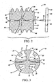
- Figs. 1-3 show a spinal implant 10, generally comprising a first element 20 and a second element 22.
- the first element 20 is coupled to the second element 22 by an internal articulation means 24 for allowing relative pivotal movement between the first and second elements.
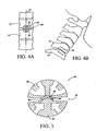
- Figures 4A and 4B show the spinal implant 10 of the present invention installed in situ , between a first vertebra 12 and a second vertebra 14.
- the implant 10 is shown implanted into an anterior aspect of the vertebral body, between the fifth cervical and sixth cervical vertebra.
- the device and method of the present invention are applicable to anterior, lateral, and posterior approaches to the vertebrae.
- the first element 20 of the implant 10 comprises first connection means, in the form of a first fusion chamber 30, for engaging the first vertebra 12. At least one opening 32 is formed in the first fusion chamber 30, to facilitate bone growth into, through and around the first fusion chamber 30 from the first vertebra 12, to fuse the first element to the first vertebra 12. Preferably, a plurality of openings 32 are provided to further promote bone ingrowth. Fusion by bone ingrowth has been found to provide a more permanent, rigid connection between the implant 10 and the skeletal structure than provided by other known connection means.
- the second element 22 of the implant 10 comprises a second connection means for engaging the second vertebra 14.
- the second connection means preferably comprises a second fusion chamber 34, substantially similar in construction to the above-described first fusion chamber 30, and comprising at least one opening 36 formed therein for facilitating bone growth into, through and around the second fusion chamber 34 from the second vertebra 14.
- the second connection means can comprise an adhesive connection, screw connection, pin connection, or any other effective alternative connection means.
- the provision of a second fusion chamber 30 is preferred, as it provides a more permanent and secure coupling than other known attachment means.
- first element 20 and first vertebra 12 are depicted in the figures as above the second element 22 and second vertebra 14, it will be understood that the present invention equally comprehends the reverse configuration wherein the first element, as described herein, is attached to a first vertebra lower on the spinal column than the second vertebra to which is attached the second element.
- the first and second elements can be fabricated from biocompatible materials including, without limitation, titanium, surgical alloys, stainless steel, chrome-molybdenum alloy, cobalt chromium alloy, zirconium oxide ceramic, nonabsorbable polymers and other anticipated biocompatible metallic or polymeric materials.
- the articulation means 24 of the present invention comprises a first articulation surface 40 provided on the first element 20, and an abutting second articulation surface 42 provided on the second element 22.
- the first and second articulation surfaces 40,42 are preferably fabricated from or coated with low-friction, wear and impact-resistant, biocompatible materials, such as, for example, titanium, stainless steel, surgical alloys, chrome molybdenum alloys, cobalt chromium alloy, zirconium oxide ceramic, non-absorbable polymers and other biocompatible metallic or polymeric materials.
- the articulation means 24 resists axial compression between the first and second elements 20, 22, but allows relative pivotal movement therebetween.
- the articulation means 24 resists axial compression between first and second vertebra 12, 14 along a support axis 44 extending generally along the spinal column, as shown, for example, in Figure 4, but permits pivotal movement between vertebrae.
- the term "pivotal,” is intended to comprehend either or both of a rotational or twisting motion about the support axis 44 (for example, rotation between cervical vertebrae by turning the head to the right or left), and/or a tilting motion angularly inclined in any direction relative to the support axis 44 (for example, nodding the head forward or backward and/or tilting the head downward to the right or left).
- Axial compression, as well as lateral translation normal to the support axis 44, is resisted between the first and second vertebra 12, 14, by providing the first internal articulation surface 40 with a void, such as a concave surface 46, which receives a protuberance, such as a convex surface 48, projecting from the second internal articulation surface 42.
- This "ball-and-socket" arrangement allows relative rotation about the support axis 44 between the first and second vertebra 12, 14.
- the articulation means 24 can be provided with one or more stops to limit the range of rotational movement allowed.
- the articulatingmeans comprises a rocker 100 and channel 101.
- the second articulation surface 42 can comprise a substantially U-shaped channel 101 extending along the length of the second element 22.
- the first articulation surface 40 may, but not in accordance with the present invention, comprise a correspondingly-shaped rocker 100 which can be, for example, hemielliptical in shape along the length of the first element 20.
- a second range of motion can be added to the articulating means 24 by modifying the shape of the channel 102.
- the modified channel 102 can be, for example but, again, not in accordance with the present invention, substantially hour-glass in shape through the depth of the channel 102.
- the channel width at the channel's base 103 and mouth 104 are greater than the channel width at the channel's midpoint 105.
- the hour-glass shaped channel 102 permits a tilting motion along two perpendicular linear planes.
- an alternative second range of motion can be added to the articulating means 24 by modifying the shape of the channel 106.
- the modified channel 106 can be, for example substantially hour-glass in shape through the length of the second element 22.
- the channel width at the channel's longitudinal midpoint 107 is less the channel width at the channel leading end 108 and tail end 109.
- the "hour-glass" shape as described herein includes various curves or straight edges so long as the width at, or near, the end points of the channel (or the top and bottom of the channel) is wider than the width at some point between the end points.
- the hour-glass shaped channel 106 permits two ranges of motion, a tilting motion and a pivoting motion about the central axis. These motions may be desirable for some patients.
- a second range of motion is added to the articulating means 24.
- This can be provided by modifying the shape of the channel 110.
- the modified channel 110 can be, for example substantially diamond in shape through the length of the second element 22.
- the channel width at the channel's longitudinal midpoint 111 is greater than the channel width at the channel leading end 112 and tail end 113.
- the first articulation surface 40 comprises a correspondingly-shaped rocker 115 which can be, for example, diamond in shape along the length of the first element 20.
- diamond shape as described herein includes various curves or straight edges so long as the width at some point between the end points of the channel (or the top and bottom of the channel) is wider than the width at, or near, the end points.
- the diamond shaped channel 110 permits three ranges of motion, a tilting motion and a pivoting motion about the central axis. These motions may be desirable for some patients.
- the articulation means 24 preferably further comprises one or more angularly offset bevels 50 formed in the first internal articulation surface 40 and/or the second internal articulation surface 42, to allow relative tilting movement between the first and second vertebra 12, 14 in one or more directions.
- the first and second internal articulation surfaces 40,42 are each provided with an angularly offset bevel 50, in a generally pyramidal configuration, as seen best in Figure 9, thereby enabling tilting movement in all directions (360°).
- a generally conical configuration is also possible and, likewise, would perm it both rotational movement and 360° tilting movement.
- the first and second articulating surfaces 40, 42 can each be provided with a general arc configuration, which provide a greater range of motion.
- the natural range of motion of the spine may be approximated by providing bevels 50 of approximately 5° around the periphery of each of the first and second articulation surfaces 40,42, thereby allowing approximately 10° of tih in all directions between adjacent vertebrae.
- the pivot point or axis of the articulation means 24 is generally centrally located on the first and second articulation surfaces 40, 42, and will be aligned with the spine's normal axis of rotation when implanted as shown in Figure 4.
- This location can be selectively varied to position the center of rotation of the articulation means 24 centrally, anteriorly, posteriorly, to the left, to the right, or eccentrically (off-center in both the anterior/posterior direction and the left/right direction) of the spine's normal axis of rotation, in order to achieve proper alignment of the spine, thereby restoring optimal sagittal and coronal spinal balance and alignment.
- the first and second elements 20, 22 of the implant 10 of the present invention preferably comprise generally hemicylindrical outer walls 60, 70 adjoining to form a generally cylindrical body.
- the first element 20 and the second element 22 abut one another with their respective first and second articulating surfaces 40,42 adjacent and engaging one another, as described above.
- the first element 20 preferably further comprises a first radiused outer wall 60.
- the one or more openings 32 for facilitating bone ingrowth are provided in this first radiused outer wall 60, and communicate with a first fusion chamber 62 formed between the first radiused outer wall 60 and the first articulating surface 40.
- the second element 22 preferably comprises a second radiused outer wall 70, defining one or more openings 36 for facilitating bone ingrowth.
- the openings 36 communicate with a second fusion chamber 72 formed between the second radiused outer wall 70 and the second articulating surface 34.
- the first and second radiused outer walls 60,70 can be provided with threads 80 to facilitate advancing the implant 10 into the intervertebral space during implantation and to help secure the implant 10 in position once implanted.
- the threads 80 on each of the first and second radiused outer walls 60, 70 are preferably aligned to form continuous threads when the first and second elements 20, 22 are engaged.
- the threads 80 can be replaced with a contoured outer surface comprising smooth, splined, flanged, spiked or beaded surface features.
- the implant 10 can further comprise one or more support flanges 85 in the first and/or second elements 20, 22, for additional strength.
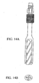
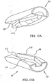
- the first and second elements 20,22 of the implant 10 of the present invention preferably comprise generally hemielliptical outer walls 97, 99 adjoining to form a generally elliptical body.
- the first element 20 preferably further comprises a first radiused outer wall 97.
- the one or more openings 32 for facilitating bone ingrowth are provided in this first radiused outer wall 97, and communicate with a first fusion chamber 62 formed between the first radiused outer wall 97 and the first articulating surface 40.
- the second element 22 preferably comprises a second radiused outer wall 99, defining one or more openings 36 for facilitating bone ingrowth.
- the openings 36 communicate with a second fusion chamber 72 formed between the second radiused outer wall 99 and the second articulating surface 42.
- the contoured outer surfaces of the first 20 and 22 second elements can comprise smooth, splined, flanged, spiked or beaded surface features to secure the element in position once implanted.
- the implant 10 can further comprise one or more support flanges 85 in the first and/or second elements 20, 22, for additional strength.
- the element 10 may be tapered along the horizontal axis.
- the tailing end 92 having a vertical radius greater then the vertical radius of the leading end 93.
- the tapered shape decreases the amount of material required to be removed and increases the ease of insertion of the implant 10 in between the first and second vertebra.
- the present invention may further comprise the provision of one or more stabilizing means for temporarily rigidly coupling the first element 20 to the second element 22 to prevent relative movement therebetween.
- the first and second elements 20, 22 be held rigidly in place during installation of the implant 10 into the intervertebral space.
- the first and second elements 20, 22 should remain rigidly coupled for a sufficient length of time after implantation to permit sufficient bone ingrowth into the fusion chambers to prevent relative motion between the implant 10 and the vertebrae 12, 14 during normal activities of the patient. Typically, approximately eight to twenty weeks of bone ingrowth will be sufficient, before the first and second elements 20, 22 are uncoupled and permitted to articulate relative to one another.
- This temporary stabilization of the first and second elements is accomplished by the present invention, without the requirement of a second surgical procedure, through the use of medium-term stabilizing means formed from bioreabsorbable material.
- bioreabsorbable materials include polyglycolate polymers or analogues, lactides, polydioxanone, polyglyconate, lactide/glycolide copolymers.
- the stabilizing means can comprise one or more biodegradable shims 82 wedged between the first element 20 and the second element 22, to prevent relative motion therebetween.
- the first and second elements 20, 22 are placed in their coupled configuration, as shown in Figs. 2-3, with the spaces between the articulating surfaces 40, 42 then being injected or filled with a biodegradable polymer, which provides the medium term temporary stabilizing means to couple the elements in position. Care will be taken to avoid filling the fusion chambers 30, 34 and the openings 32, 36 to the fusion chambers with the polymer, which could inhibit bone ingrowth. The threads 82 will also remain exposed to assist in implantation of the device.
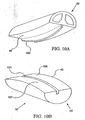
- the stabilizing means comprise a removable and/or bioreabsorbable endcap 90, which releasably engages the tailing end 92 of the implant 10 to couple the first and second elements 20, 22.
- the endcap can comprise one or more clips 94 for engaging the implant 10, and one or more keyways 96 for engaging a wrench, driver or other actuation device used to advance the implant 10 into the intervertebral space.
- a second removable and/or absorbable endcap can be installed on the leading end 93 of the implant 10.
- the endcaps may additionally function to retain the bone fragments within the chambers 62,72 of the fusion chambers 30, 34, as will be described in greater detail below, until sufficient bone ingrowth and fusion has occurred.
- FIG. 5 shows an implant 10, generally comprising first and second elements 20, 22, substantially as described above, and further comprising an intermediate articulation element, which in the depicted embodiment comprises a generally hemispherical bowl-shaped cap 90 interposed between the concave surface 46 of the first element 20 and the convex surface 48 of the second element 22.
- the cap 90 is preferably fabricated from a wear-resistant, low friction material of construction, which may be somewhat resilient to absorb impact loading. The provision of the cap 90 allows articulation at the interface between the top surface of the cap and the concave surface 46 of the first element 20 , and between the bottom surface of the cap and the convex surface 48 of the second element 22, resulting in a bipolar articulation.
- This arrangement reduces frictional wear on the articulation surfaces by distributing wear over two articulation interfaces.
- the present invention can be used for maintaining a desired intervertebral space between a first vertebra 12 and a second vertebra 14.
- the method of use preferably comprises removing a section of the first vertebra to form a cavity therein, mounting a first element of an articulating spinal implant into the cavity, and connectinga second element of the implant to the second vertebra.
- the articulating spinal implant used to carry out this method is preferably substantially similar to the example embodiment described above, having first and second internal articulation surfaces which adjoin to form a joint allowing relative pivotal movement between the first and second elements, but preventing relative axial compression therebetween.
- At least one of the elements preferably further comprises a fusion chamber, including a chamber and at least one opening communicating with the chamber, for facilitating bone ingrowth into, through and around the fusion chamber from the respective vertebra.
- the method of use of a device according to the present invention comprises attachment of both the first and second elements of the implant to the respective vertebra using fusion chambers for bone ingrowth.
- a section of the second vertebra is preferably removed to form a cavity therein for receiving the second element of the implant.
- the method can further comprise the insertion of bone fragments, which may be the fragments formed in the above-described removal of vertebral sections, into the fusion chamber(s) of the implant.
- the presence of these bone fragments has been shown to stimulate and enhance bone ingrowth into the fusion chamber.
- the method anticipates the application of means for stimulating bone growth into, through, and/or around the fusion chamber(s).
- the means for stimulating bone growth can comprise, for example, electrical or magnetic bone growth stimulators, bone morphogenetic protein (BMP), hydroxyl apatite compounds, demineralized bone compound, and/or other bone growth stimulating devices or compounds. It is also anticipated that the introduction of a cyanoacrylate ,material, commonly referred to as surgical glue, onto the outer surface of the fusion chamber(s) may be used to fix the implant in optimal position awaiting bone ingrowth.
- BMP bone morphogenetic protein
- hydroxyl apatite compounds demineralized bone compound
- demineralized bone compound demineralized bone compound
- the method may utilize standard surgical approachesto the spine from either an anterior approach for the cervical and thoracic spinal segments, or from an anterior or posterior lateral approach to the lumbar spinal segments.
- the removal of vertebral sections may be accomplished by drilling or chipping a generally circular bore having a diameter and depth adapted to generally match the implant to be utilized, bridging the first and second vertebra.
- the circular bore may be tapered with the leading end diameter being smaller then the tail end diameter.
- the bore is preferably centered over the intervertebral space, approximately midway between the first and second vertebra. Threads may then be tapped into the bore to facilitate insertion of the implant.
- the removal of vertebral sections may be accomplished by using a unique surgical instrument, as shown in Figure 14, for drilling an elliptical bore having a major and minor diameter and depth adapted to generally match the implant to be utilized, bridging the first and second vertebra.
- the surgical instrument is affixed to a drill to provide rotational power to the cutting portion.
- the cutting portion of the surgical instrument consists of a circular flute drill bit sheathed within cutting blades formed in a elliptical shape. The flute drill bit extends out beyond cutting blades to cut a circular section between the first and second vertebra. As the drill bit cuts into the vertebra the cutting blades then remove the remaining material to form a elliptical bore having a major and minor diameter and depth adapted to generally match the implant to be utilized, bridging the first and second vertebra.
- the implant can be provided with self-tapping threads.
- the implant is assembled with the first and second articulating surfaces engaged, and the first and second elements of the implant are rigidly coupled by stabilizing means substantially as described above.
- the stabilized implant is advanced into the bore to the desired depth.
- the implant is advanced until the tailing end 92 is flush or slightly recessed relative to the outer surface of the vertebrae, thereby eliminating the possibility that outwardly projecting portions of the implant may interfere with or injure adjacent or regional vascular, neural or visceral structures.
- two articulating implants can be placed in parallel positions with the lengthwise axis of each adjacent one to the other, in a generally parallel arrangement, allowing flexion/extension movement alone.
- This arrangement will typically require removal of vertebral material to form two openings, or an extended opening to accommodate both implants.
- a single, appropriately sized implant could be placed in the interspace utilizing the transabdominal open surgical approach, the transabdominal laparoscopic approach, or the retroperitoneal open anterior approach allowing pivotal motion around the single point of articulation as described above for use in cervical and thoracic intervertebral disc spaces.
- the stabilizing means is dissolved and absorbed into the body, uncoupling the articulation means to permit relative motion between the first and second elements, thus preserving spinal flexibility and minimizing destructive stress upon adjacent intervertebral joints.
- the implant resists axial compression between the first and second elements, and thereby prevents relative compression between the first and second vertebra, thus maintaining the desired intervertebral space. Further, the implant is recessed into the recipient vertebral site, eliminating impingement on next adjacent vascular, neural or visceral structures.
Abstract
Description
- The invention relates generally to a spinal implant for use in intervertebral disc replacement; and more specifically relates to an articulating implant that fuses to adjacent vertebrae by bone ingrowth, thus restoring proper intervertebral spacing, and eliminating nerve root and/or spinal cord compression, while preserving spinal flexibility.
- The spinal column is formed from a number of vertebrae, which in their normal state are separated from one another by cartilaginous intervertebral discs. These discs form a cushion between adjacent vertebrae, resisting compression along the support axis of the spinal column, but permitting limited movement between the vertebrae to provide the characteristic flexibility of the healthy spine. Injury, disease or other degenerative disorders may cause one or more intervertebral discs to shrink, collapse, deteriorate or become displaced, herniated or otherwise damaged. This can lead to compression of adjacent nerve root(s) or the spinal cord causing chronic and often disabling pain, and in advanced circumstances, irreversible paralysis of upper and/or lower limbs.
- A number of devices and methods have been suggested for the replacement of damaged or dislocated intervertebral discs. One common approach is to permanently stabilize or "fuse" the adjacent vertebrae to maintain the proper intervertebral spacing and eliminate relative movement between the vertebrae. Various methods of vertebral stabilization have been developed. For example, autogenous grafts of dowel-shaped sections of bone have been implanted between the vertebrae to cause bone growth across the intervertebral space, thereby fusing the adjacent vertebrae into one bone mass. This procedure disadvantageously requires the harvest of donor bone for the graft from other parts of the patient's body, typically requiring a separate surgical procedure and resultant increases in complications and expense. An alternative source is cadaver bone, with potential complications of transmissible diseases, impaired graft incorporation, collapse or displacement. A further development to this method of vertebral stabilization involves the implantation of a perforated cylindrical bone basket between adjacent vertebrae. Bone fragments produced in preparing the vertebrae for the implantation are inserted into the bone basket to promote bone growth into, through and around the basket.
- Vertebral stabilization by fusion of adjacent vertebrae has proven successful in permanently preserving intervertebral spacing, but has been found to present a number of disadvantages. Fusion of adjacent vertebrae necessarily eliminates a portion of the spine's normal range of motion, thereby reducing the subject's spinal flexibility. Additionally, fusion of the vertebrae increases the stresses imposed on adjacent mobile portions of the spinal column, often hastening the subsequent breakdown of normal joint surfaces above and below the fused vertebrae.
- It has also been proposed to replace an injured intervertebral disc with a prosthesis which is "jointed" to permit relative movement between vertebrae. Previously-known devices of this type generally have been found to suffer from inadequate attachment between the prosthesis and the vertebrae. The intended movement between the components of previously-known jointed prostheses can cause relative motion between the prosthesis and adjacent bone surface(s). Because such motion would disrupt bone ingrowth, jointed prostheses have generally been considered incompatible with attachment by bone ingrowth. In addition, because the joint elements of these devices typically must occupy a substantial vertical extent in order to achieve the desired range of motion, and yet must fit within the intervertebral space, attachment of such devices generally has been by use of flat plates or surfaces provided on either side of the joint elements as points of fixation to the vertebrae. An example of a prosthetic device utilizing this method of attachment is disclosed in WO 98/14142. This method of attachment may be accomplished by compressive or friction fits, spiked projections, screws or pins, complemented in some instance with tissue ingrowth into porous surfaces. These mechanisms of attachment, however, may lack the degree and strength of fixation desired. Moreover, several such devices have used attachment flanges which extend beyond the surfaces of the vertebrae to which the device is attached. This has been found undesirable, as the extending flanges may interfere with or injure adjacent tissue. For example, it has been reported that flanges extending into immediately adjacent delicate esophageal area may interfere with swallowing and speech, or cause perforation and potentially fatal infection. An additional drawback to the use of screw and pin connections is the potential for such connectors to dislodge and cause injury.
- Thus, it can be seen that a need yet exists for a spinal implant effective in permanently maintaining intervertebral spacing to prevent nerve or spinal cord compression while preserving as much of the natural range of motion between the affected vertebrae as possible. A need further exists for such a device which is capable of forming a permanent, strong attachment to the vertebrae and yet does not protrude beyond the external surfaces to which it is attached. Still another need exists for a device for replacing a damaged or displaced disc, which maintains intervertebral spacing to prevent nerve and spinal cord compression, while preserving the natural relative motion between the vertebrae. It is to the provision of a device meeting these and other needs that the present invention is primarily directed.
- Accordingly, the invention provides a spinal implant according to
claim 1. - The implant also includes internal articulation means, coupling the first element to the second element, for allowing relative movement between the first element and the second element The term "internal articulation means," is intended to mean a device that permits relative motion between components of the device, rather than between the device and an external structure such as adjacent bone or other tissue.
- In specific embodiments of the subject invention, the first and second element may have either hemicylindrical or hemielliptical shaped outer surfaces. The first and second elements each having an outer wall perforated with one or more openings provided therein to allow bone ingrowth into the fusion chambers, and having abutting joint surfaces forming the internal articulation means. In a further preferred embodiment, the joint surfaces are formed as engaging concave and convex surfaces to create a ball-and-socket type joint (or groove and channel, or other such joint), which allows relative pivotal motion between the vertebrae, but resists compression therebetween.
- The first and second elements can join to form a single element which can be implanted using methods similar to those followed in the implantation of previously-known non-articulating vertebral fusion implants. Temporary stabilizing means can be provided for rigidly coupling the first and second elements by interposition of bioreabsorbable elements to permit implantation and enable bone ingrowth into the fusion chambers and fusion of the first and second elements to adjacent bone during an initial stabilization period, after which said temporary means biodegrades permitting articulation between the first and second elements.
- The present invention preferably includes first connection means for connecting the first articulation surface to a first vertebra, and second connection means for connecting the second articulation surface to a second vertebra. The first and second articulation surfaces resist axial compression between the first and second elements in the direction of the support axis, but allow relative pivotal motion between the first and second elements. At least one, and preferably both, of the first connection means and the second connection means comprise a fusion chamber having at least one opening therein for facilitating bone ingrowth, thereby permanently and securely affixing the implant in place.
- The present invention can be used for maintaining an intervertebral space between a first vertebra and second vertebra. The device is used by removing a section of the first vertebra to form a cavity therein, mounting a first element of a spinal implant within the cavity formed in the first vertebra, and connecting a second element of the spinal implant to the second vertebra. The first element includes a first articulation surface and a first fusion chamber having at least one opening therein for facilitating bone ingrowth from the first vertebra. The second element includes a second articulation surface, wherein the first and second articulation surfaces adjoin to form a joint allowing relative pivotal movement between the first and second elements but preventing relative compression between the first and second elements. In a further preferred embodiment, a section of the second vertebra may be removed to form a cavity for receiving the second element. The second element may also include a second fusion chamber for facilitating bone ingrowth from the second vertebra. Bone fragments formed by the removal of vertebral sections to accommodate implantation or bone growth stimulating compounds or devices may be inserted into the fusion chamber(s) to enhance bone ingrowth.
- These and other objects, features and advantages of the present invention will be more readily understood with reference to the following detailed description, which is given by way of example only, read in conjunction with the accompanying drawing figures.
- Figures 1a and 1b show a perspective view of a spinal implant according to one cylindrical form
- Figure 2 shows a cross-sectional side view of the spinal implant of Figure 1.
- Figure 3 shows a cross-sectional end view of the spinal implant of Figure 1.
- Figure 4a is an end view of a spinal implant in situ according to the cylindrical form of the present invention.
- Figure 4b is a side view of a spinal implant in-situ according to the cylindrical form of the present invention.
- Figure 5 is a cross sectional end view of another embodiment of the present invention.
- Figure 6a shows a cross-sectional end view of an elliptically shaped spinal implant of the subject invention.
- Figure 6b shows cross-sectional end view of an alternative elliptically shaped spinal implant of the subject invention.
- Figure 7 shows a cross-sectional side view of the tapered spinal implant.
- Figure 8 shows a cross-sectionalend view of a spinal implant with a rocker and channel articulating means.
- Figure 9 shows a cross-sectional end view of a spinal implant with a rocker and hour-glass channel articulating means.
- Figures 10a & 10b show a perspective view of a spinal implant with a rocker and alternative hour-glass channel articulating means.
- Figures 11a & 11b show a perspective view of a spinal implant with a rocker and alternative hour-glass channel articulating means.
- Figure 12 is an end view of a spinal implant in-situ according to the elliptical form of the present invention.
- Figure 13 is a side view of a spinal implant in-situ according to the tapered form of the present invention.
- Figure 14 shows a surgical instrument for cutting an elliptical section in between spinal vertebra.
- Figures 15a & 15b show a perspective view of a spinal implant with an alternative diamond channel and corresponding diamond rocker articulating means according to the present invention.
- Referring now in detail to the figures wherein like reference numbers represent like parts throughout, preferred forms of the present invention will now be described. Figs. 1-3 show a
spinal implant 10, generally comprising afirst element 20 and asecond element 22. Thefirst element 20 is coupled to thesecond element 22 by an internal articulation means 24 for allowing relative pivotal movement between the first and second elements. - Figures 4A and 4B show the
spinal implant 10 of the present invention installed in situ, between afirst vertebra 12 and asecond vertebra 14. Theimplant 10 is shown implanted into an anterior aspect of the vertebral body, between the fifth cervical and sixth cervical vertebra. The device and method of the present invention, however, are applicable to anterior, lateral, and posterior approaches to the vertebrae. - As seen best in Figs. 2-3, the
first element 20 of theimplant 10 comprises first connection means, in the form of afirst fusion chamber 30, for engaging thefirst vertebra 12. At least oneopening 32 is formed in thefirst fusion chamber 30, to facilitate bone growth into, through and around thefirst fusion chamber 30 from thefirst vertebra 12, to fuse the first element to thefirst vertebra 12. Preferably, a plurality ofopenings 32 are provided to further promote bone ingrowth. Fusion by bone ingrowth has been found to provide a more permanent, rigid connection between theimplant 10 and the skeletal structure than provided by other known connection means. - The
second element 22 of theimplant 10 comprises a second connection means for engaging thesecond vertebra 14. The second connection means preferably comprises asecond fusion chamber 34, substantially similar in construction to the above-describedfirst fusion chamber 30, and comprising at least oneopening 36 formed therein for facilitating bone growth into, through and around thesecond fusion chamber 34 from thesecond vertebra 14. Alternatively, the second connection means can comprise an adhesive connection, screw connection, pin connection, or any other effective alternative connection means. However, the provision of asecond fusion chamber 30 is preferred, as it provides a more permanent and secure coupling than other known attachment means. Although thefirst element 20 andfirst vertebra 12 are depicted in the figures as above thesecond element 22 andsecond vertebra 14, it will be understood that the present invention equally comprehends the reverse configuration wherein the first element, as described herein, is attached to a first vertebra lower on the spinal column than the second vertebra to which is attached the second element. The first and second elements can be fabricated from biocompatible materials including, without limitation, titanium, surgical alloys, stainless steel, chrome-molybdenum alloy, cobalt chromium alloy, zirconium oxide ceramic, nonabsorbable polymers and other anticipated biocompatible metallic or polymeric materials. - Referring now to Figs. 2-3, the articulation means 24 of the present invention comprises a
first articulation surface 40 provided on thefirst element 20, and an abuttingsecond articulation surface 42 provided on thesecond element 22. The first and second articulation surfaces 40,42 are preferably fabricated from or coated with low-friction, wear and impact-resistant, biocompatible materials, such as, for example, titanium, stainless steel, surgical alloys, chrome molybdenum alloys, cobalt chromium alloy, zirconium oxide ceramic, non-absorbable polymers and other biocompatible metallic or polymeric materials. The articulation means 24 resists axial compression between the first andsecond elements second vertebra - Axial compression, as well as lateral translation normal to the support axis 44, is resisted between the first and
second vertebra internal articulation surface 40 with a void, such as aconcave surface 46, which receives a protuberance, such as aconvex surface 48, projecting from the secondinternal articulation surface 42. This "ball-and-socket" arrangement allows relative rotation about the support axis 44 between the first andsecond vertebra - In addition to the "ball-and socket" arrangement for the articulating means 24 other configurations are possible. As shown in Figures 8 and 10, the articulatingmeans comprises a
rocker 100 andchannel 101. Thesecond articulation surface 42 can comprise a substantiallyU-shaped channel 101 extending along the length of thesecond element 22. Thefirst articulation surface 40 may, but not in accordance with the present invention, comprise a correspondingly-shapedrocker 100 which can be, for example, hemielliptical in shape along the length of thefirst element 20. Such an arrangement permits only a tilting motion in one plane. In an alternative, as shown in Figure 9, a second range of motion can be added to the articulatingmeans 24 by modifying the shape of thechannel 102. The modifiedchannel 102 can be, for example but, again, not in accordance with the present invention, substantially hour-glass in shape through the depth of thechannel 102. The channel width at the channel'sbase 103 andmouth 104 are greater than the channel width at the channel'smidpoint 105. The hour-glass shapedchannel 102 permits a tilting motion along two perpendicular linear planes. - As shown in Figures 11a and 11b, an alternative second range of motion can be added to the articulating
means 24 by modifying the shape of thechannel 106. The modifiedchannel 106 can be, for example substantially hour-glass in shape through the length of thesecond element 22. The channel width at the channel'slongitudinal midpoint 107 is less the channel width at thechannel leading end 108 andtail end 109. Those skilled in the art, having the benefit of the instant disclosure, will appreciate that the "hour-glass" shape as described herein includes various curves or straight edges so long as the width at, or near, the end points of the channel (or the top and bottom of the channel) is wider than the width at some point between the end points. The hour-glass shapedchannel 106 permits two ranges of motion, a tilting motion and a pivoting motion about the central axis. These motions may be desirable for some patients. - According to the present invention and as shown in Figures 15a and 15b, a second range of motion is added to the articulating
means 24. This can be provided by modifying the shape of thechannel 110. The modifiedchannel 110 can be, for example substantially diamond in shape through the length of thesecond element 22. The channel width at the channel'slongitudinal midpoint 111 is greater than the channel width at thechannel leading end 112 andtail end 113. Additionally, thefirst articulation surface 40 comprises a correspondingly-shaped rocker 115 which can be, for example, diamond in shape along the length of thefirst element 20. Those skilled in the art, having the benefit of the instant disclosure, will appreciate that the "diamond" shape as described herein includes various curves or straight edges so long as the width at some point between the end points of the channel (or the top and bottom of the channel) is wider than the width at, or near, the end points. The diamond shapedchannel 110 permits three ranges of motion, a tilting motion and a pivoting motion about the central axis. These motions may be desirable for some patients. - The articulation means 24 preferably further comprises one or more angularly offset
bevels 50 formed in the firstinternal articulation surface 40 and/or the secondinternal articulation surface 42, to allow relative tilting movement between the first andsecond vertebra bevel 50, in a generally pyramidal configuration, as seen best in Figure 9, thereby enabling tilting movement in all directions (360°). A generally conical configuration is also possible and, likewise, would perm it both rotational movement and 360° tilting movement. Additionally, as shown in Figures 10 and 11, the first and second articulatingsurfaces - The natural range of motion of the spine may be approximated by providing
bevels 50 of approximately 5° around the periphery of each of the first and second articulation surfaces 40,42, thereby allowing approximately 10° of tih in all directions between adjacent vertebrae. As depicted in the figures, the pivot point or axis of the articulation means 24 is generally centrally located on the first and second articulation surfaces 40, 42, and will be aligned with the spine's normal axis of rotation when implanted as shown in Figure 4. This location, however, can be selectively varied to position the center of rotation of the articulation means 24 centrally, anteriorly, posteriorly, to the left, to the right, or eccentrically (off-center in both the anterior/posterior direction and the left/right direction) of the spine's normal axis of rotation, in order to achieve proper alignment of the spine, thereby restoring optimal sagittal and coronal spinal balance and alignment. - As shown best by Figure 1, the first and
second elements implant 10 of the present invention preferably comprise generally hemicylindricalouter walls first element 20 and thesecond element 22 abut one another with their respective first and second articulatingsurfaces first element 20 preferably further comprises a first radiusedouter wall 60. The one ormore openings 32 for facilitating bone ingrowth are provided in this first radiusedouter wall 60, and communicate with afirst fusion chamber 62 formed between the first radiusedouter wall 60 and the first articulatingsurface 40. Similarly, thesecond element 22 preferably comprises a second radiusedouter wall 70, defining one ormore openings 36 for facilitating bone ingrowth. Theopenings 36 communicate with asecond fusion chamber 72 formed between the second radiusedouter wall 70 and the second articulatingsurface 34. The first and second radiusedouter walls threads 80 to facilitate advancing theimplant 10 into the intervertebral space during implantation and to help secure theimplant 10 in position once implanted. Thethreads 80 on each of the first and second radiusedouter walls second elements threads 80, and/or to configure thethreads 80 to direct bone fragments generated by implantation into theopenings 32, as taught by U.S. Patent No. 5,489,308 to Kuslich et al. In other less preferred embodiments, thethreads 80 can be replaced with a contoured outer surface comprising smooth, splined, flanged, spiked or beaded surface features. Theimplant 10 can further comprise one ormore support flanges 85 in the first and/orsecond elements - As shown best by Figures 6a, 6b and 12, the first and
second elements implant 10 of the present invention preferably comprise generally hemiellipticalouter walls first element 20 and thesecond element 22 abut one another with their respective first and second articulatingsurfaces first element 20 preferably further comprises a first radiusedouter wall 97. The one ormore openings 32 for facilitating bone ingrowth are provided in this first radiusedouter wall 97, and communicate with afirst fusion chamber 62 formed between the first radiusedouter wall 97 and the first articulatingsurface 40. Similarly, thesecond element 22 preferably comprises a second radiusedouter wall 99, defining one ormore openings 36 for facilitating bone ingrowth. Theopenings 36 communicate with asecond fusion chamber 72 formed between the second radiusedouter wall 99 and the second articulatingsurface 42. In alternative embodiments the contoured outer surfaces of the first 20 and 22 second elements can comprise smooth, splined, flanged, spiked or beaded surface features to secure the element in position once implanted. Theimplant 10 can further comprise one ormore support flanges 85 in the first and/orsecond elements - In another preferred embodiment, as shown in Figures 7 and 12, the
element 10 may be tapered along the horizontal axis. The tailingend 92 having a vertical radius greater then the vertical radius of theleading end 93. The tapered shape decreases the amount of material required to be removed and increases the ease of insertion of theimplant 10 in between the first and second vertebra. - In a further preferred embodiment, the present invention may further comprise the provision of one or more stabilizing means for temporarily rigidly coupling the
first element 20 to thesecond element 22 to prevent relative movement therebetween. For example, it is preferred that the first andsecond elements implant 10 into the intervertebral space. In addition, the first andsecond elements implant 10 and thevertebrae second elements implant 10 are uncoupled, allowing articulation. In one example embodiment, depicted in Figure 3, the stabilizing means can comprise one or morebiodegradable shims 82 wedged between thefirst element 20 and thesecond element 22, to prevent relative motion therebetween. In another example embodiment, the first andsecond elements surfaces fusion chambers openings threads 82 will also remain exposed to assist in implantation of the device. In another example embodiment, depicted in Figure 2, the stabilizing means comprise a removable and/orbioreabsorbable endcap 90, which releasably engages the tailingend 92 of theimplant 10 to couple the first andsecond elements more clips 94 for engaging theimplant 10, and one ormore keyways 96 for engaging a wrench, driver or other actuation device used to advance theimplant 10 into the intervertebral space. A second removable and/or absorbable endcap can be installed on the leadingend 93 of theimplant 10. The endcaps may additionally function to retain the bone fragments within thechambers fusion chambers - Another preferred embodiment of the present invention is depicted by Figure 5, which shows an
implant 10, generally comprising first andsecond elements cap 90 interposed between theconcave surface 46 of thefirst element 20 and theconvex surface 48 of thesecond element 22. Thecap 90 is preferably fabricated from a wear-resistant, low friction material of construction, which may be somewhat resilient to absorb impact loading. The provision of thecap 90 allows articulation at the interface between the top surface of the cap and theconcave surface 46 of thefirst element 20, and between the bottom surface of the cap and theconvex surface 48 of thesecond element 22, resulting in a bipolar articulation. This arrangement reduces frictional wear on the articulation surfaces by distributing wear over two articulation interfaces. The engagement of the concave lower surface of thecap 90 with theconvex surface 48 of thesecond element 22, and the engagement of the convex upper surface of thecap 90 with theconcave surface 46 of thefirst element 20, prevents thecap 90 from becoming dislodged when theimplant 10 is installed. - The present invention can be used for maintaining a desired intervertebral space between a
first vertebra 12 and asecond vertebra 14. The method of use preferably comprises removing a section of the first vertebra to form a cavity therein, mounting a first element of an articulating spinal implant into the cavity, and connectinga second element of the implant to the second vertebra. The articulating spinal implant used to carry out this method is preferably substantially similar to the example embodiment described above, having first and second internal articulation surfaces which adjoin to form a joint allowing relative pivotal movement between the first and second elements, but preventing relative axial compression therebetween. At least one of the elements preferably further comprises a fusion chamber, including a chamber and at least one opening communicating with the chamber, for facilitating bone ingrowth into, through and around the fusion chamber from the respective vertebra. In a preferred form, the method of use of a device according to the present invention comprises attachment of both the first and second elements of the implant to the respective vertebra using fusion chambers for bone ingrowth. In this embodiment, a section of the second vertebra is preferably removed to form a cavity therein for receiving the second element of the implant. The method can further comprise the insertion of bone fragments, which may be the fragments formed in the above-described removal of vertebral sections, into the fusion chamber(s) of the implant. The presence of these bone fragments has been shown to stimulate and enhance bone ingrowth into the fusion chamber. In another embodiment, the method, anticipates the application of means for stimulating bone growth into, through, and/or around the fusion chamber(s). The means for stimulating bone growth can comprise, for example, electrical or magnetic bone growth stimulators, bone morphogenetic protein (BMP), hydroxyl apatite compounds, demineralized bone compound, and/or other bone growth stimulating devices or compounds. It is also anticipated that the introduction of a cyanoacrylate ,material, commonly referred to as surgical glue, onto the outer surface of the fusion chamber(s) may be used to fix the implant in optimal position awaiting bone ingrowth. - implantation of the articulating spinal implant according to the present invention may be carried out in a manner generally similar to previously-known methods for the implantation of non-articulating, rigid-fusion implants, with exceptions as set out herein. For example, the method may utilize standard surgical approachesto the spine from either an anterior approach for the cervical and thoracic spinal segments, or from an anterior or posterior lateral approach to the lumbar spinal segments. The removal of vertebral sections may be accomplished by drilling or chipping a generally circular bore having a diameter and depth adapted to generally match the implant to be utilized, bridging the first and second vertebra. Additionally, the circular bore may be tapered with the leading end diameter being smaller then the tail end diameter. The bore is preferably centered over the intervertebral space, approximately midway between the first and second vertebra. Threads may then be tapped into the bore to facilitate insertion of the implant.
- In an alternative method, the removal of vertebral sections may be accomplished by using a unique surgical instrument, as shown in Figure 14, for drilling an elliptical bore having a major and minor diameter and depth adapted to generally match the implant to be utilized, bridging the first and second vertebra. Preferably, the surgical instrument is affixed to a drill to provide rotational power to the cutting portion. The cutting portion of the surgical instrument consists of a circular flute drill bit sheathed within cutting blades formed in a elliptical shape. The flute drill bit extends out beyond cutting blades to cut a circular section between the first and second vertebra. As the drill bit cuts into the vertebra the cutting blades then remove the remaining material to form a elliptical bore having a major and minor diameter and depth adapted to generally match the implant to be utilized, bridging the first and second vertebra.
- Alternatively, the implant can be provided with self-tapping threads. The implant is assembled with the first and second articulating surfaces engaged, and the first and second elements of the implant are rigidly coupled by stabilizing means substantially as described above. The stabilized implant is advanced into the bore to the desired depth. Preferably, the implant is advanced until the tailing
end 92 is flush or slightly recessed relative to the outer surface of the vertebrae, thereby eliminating the possibility that outwardly projecting portions of the implant may interfere with or injure adjacent or regional vascular, neural or visceral structures. - In the lumbar area, where greater load bearing is required, two articulating implants can be placed in parallel positions with the lengthwise axis of each adjacent one to the other, in a generally parallel arrangement, allowing flexion/extension movement alone. This arrangement will typically require removal of vertebral material to form two openings, or an extended opening to accommodate both implants. Alternatively, a single, appropriately sized implant could be placed in the interspace utilizing the transabdominal open surgical approach, the transabdominal laparoscopic approach, or the retroperitoneal open anterior approach allowing pivotal motion around the single point of articulation as described above for use in cervical and thoracic intervertebral disc spaces.
- Post-operatively, bone ingrowth will occur, fusing the first and/or second elements of the implant to the respective vertebra. After sufficient passage of time, the stabilizing means is dissolved and absorbed into the body, uncoupling the articulation means to permit relative motion between the first and second elements, thus preserving spinal flexibility and minimizing destructive stress upon adjacent intervertebral joints. The implant resists axial compression between the first and second elements, and thereby prevents relative compression between the first and second vertebra, thus maintaining the desired intervertebral space. Further, the implant is recessed into the recipient vertebral site, eliminating impingement on next adjacent vascular, neural or visceral structures.
Claims (19)
- A spinal implant (10), comprising:a first element (20) comprising a first articulation surface (40), a first outer surface (60, 97) and a first connection means for engaging a first vertebra (12);a second element (22) comprising a second articulation surface (42), a second outer surface (70, 99) and a second connection means for engaging a second vertebra (14); andan articulation means, coupling said first articulation surface to said second articulation surface for allowing relative movement between said first element and said second element, wherein said articulation means resists axial compression in the direction of a support axis; characterised in that said articulation means (40) comprises a channel (111) along a length of said second element (22) and a rocker along a length of said first element (20), wherein at least a portion of said rocker (113) is engaged within said channel (111), said rocker (113) and said channel each having first and second ends, said rocker (113) and said channel each having a width at some point between said first and second ends that is greater than a width at or adjacent to said first and second ends.
- The spinal implant of claim 1, wherein said rocker and said channel (113) are substantially diamond shaped.
- The spinal implant of any preceding claim, wherein said rocker (113) defines a convex articulation surface that cooperates with an articulation surface defined by said elongate channel (111) to allow said relative movement between said first element (20) and said second element (22).
- The spinal implant of any preceding claim, wherein said convex articulation surface comprises a lateral curvature extending across said rocker width.
- The spinal implant of any preceding claim, wherein an intermediate articulation element (90) is positioned between said first and second articulation surfaces (40, 42).
- The spinal implant of claim 5, wherein said first articulation surface (40) comprises a concave surface (46), and said second articulation surface (42) comprises a convex surface (48), and said intermediate articulation element (90) comprises a generally hemispherical cap (90).
- The spinal implant of any of claims 1 to 6, further comprising a leading end (93) and a tailing end (92), the spinal implant defining a taper between said leading and tailing ends (93, 92).
- The spinal implant of any preceding claim, including a tailing end (92) and a leading end (93), wherein a first radius of said tailing end (92) is greater than a second radius of said leading end (93).
- The spinal implant of any preceding claim, wherein at least one of said first and second elements (20, 22) includes a fusion chamber (30, 34) and at least one opening (32, 36) extending through said outer surface (60, 70, 97, 99) and in communication with said fusion chamber (30, 34) to allow bone ingrowth into said fusion chamber (30, 34).
- The spinal implant of any preceding claim, wherein said first outer surface (60, 97) comprises a first radiused outer wall (60, 97) and said second outer surface (70, 99) comprises a second radiused outer wall (70, 99).
- The spinal implant of claim 10, wherein said first radiused outer wall (60, 97) and said second radiused outer wall (60, 99) comprise securing means for securing the spinal implant (10) within a cavity between the first vertebra and the second vertebra.
- The spinal implant of any preceding claim, wherein said first outer surface (60, 97) and said second outer surface (70, 99) each comprise a threaded outer surface (80).
- The spinal implant of any preceding claim, further comprising stabilising means for temporarily rigidly coupling said first element (20) to said second element (22).
- The spinal implant of any preceding claim, wherein said stabilising means comprises an endcap (90) adapted to releasably engage a portion of said first element (20) and a portion of said second element (22).
- The spinal implant of claim 14, wherein said stabilising means comprises at least one bioreabsorbable element (82) adapted to be absorbed subsequent to implantation.
- The spinal implant of any preceding claim, wherein said first and second outer surfaces (60, 70) of said first and second elements (20, 22) are convex and cooperate to form a generally cylindrical shaped implant body.
- The spinal implant of any of claims 1 to 16, wherein said first outer surface (60) and said second outer surface (70) each comprise a hemicylindrical outer surface.
- The spinal implant of any of claims 1 to 15, wherein said first and second outer surfaces (97, 99) are convex and cooperate to form a generally elliptical shaped implant body.
- The spinal implant of any of claims 1 to 15 or 18, wherein said first convex outer surface (97) and said second outer surface (99) each comprise a hemielliptical outer surface (97, 99).
Applications Claiming Priority (4)
| Application Number | Priority Date | Filing Date | Title |
|---|---|---|---|
| US09/065,816 US6019792A (en) | 1998-04-23 | 1998-04-23 | Articulating spinal implant |
| US09/389,758 US6440168B1 (en) | 1998-04-23 | 1999-09-02 | Articulating spinal implant |
| US389758 | 1999-09-02 | ||
| PCT/US2000/022939 WO2001015638A1 (en) | 1998-04-23 | 2000-08-21 | Articulating spinal implant |
Publications (2)
| Publication Number | Publication Date |
|---|---|
| EP1214027A1 EP1214027A1 (en) | 2002-06-19 |
| EP1214027B1 true EP1214027B1 (en) | 2007-05-16 |
Family
ID=26746030
Family Applications (1)
| Application Number | Title | Priority Date | Filing Date |
|---|---|---|---|
| EP00957633A Expired - Lifetime EP1214027B1 (en) | 1998-04-23 | 2000-08-21 | Articulating spinal implant |
Country Status (10)
| Country | Link |
|---|---|
| US (2) | US6019792A (en) |
| EP (1) | EP1214027B1 (en) |
| JP (1) | JP2003512090A (en) |
| CN (1) | CN1262253C (en) |
| AT (1) | ATE362353T1 (en) |
| AU (1) | AU778600B2 (en) |
| CA (1) | CA2382572A1 (en) |
| DE (1) | DE60034893T2 (en) |
| ES (1) | ES2284520T3 (en) |
| WO (1) | WO2001015638A1 (en) |
Families Citing this family (481)
| Publication number | Priority date | Publication date | Assignee | Title |
|---|---|---|---|---|
| US7494507B2 (en) * | 2000-01-30 | 2009-02-24 | Diamicron, Inc. | Articulating diamond-surfaced spinal implants |
| US6679915B1 (en) * | 1998-04-23 | 2004-01-20 | Sdgi Holdings, Inc. | Articulating spinal implant |
| DE19818143A1 (en) * | 1998-04-23 | 1999-10-28 | Medinorm Ag | Device for connecting vertebrae of the spine |
| US6179874B1 (en) * | 1998-04-23 | 2001-01-30 | Cauthen Research Group, Inc. | Articulating spinal implant |
| US6231609B1 (en) * | 1998-07-09 | 2001-05-15 | Hamid M. Mehdizadeh | Disc replacement prosthesis |
| AU748746B2 (en) * | 1998-07-22 | 2002-06-13 | Spinal Dynamics Corporation | Threaded cylindrical multidiscoid single or multiple array disc prosthesis |
| US6183517B1 (en) * | 1998-12-16 | 2001-02-06 | Loubert Suddaby | Expandable intervertebral fusion implant and applicator |
| US6110210A (en) * | 1999-04-08 | 2000-08-29 | Raymedica, Inc. | Prosthetic spinal disc nucleus having selectively coupled bodies |
| CA2376097A1 (en) | 1999-06-04 | 2000-12-14 | Sdgi Holdings, Inc. | Artificial disc implant |
| US6520996B1 (en) | 1999-06-04 | 2003-02-18 | Depuy Acromed, Incorporated | Orthopedic implant |
| CA2391330C (en) | 1999-07-02 | 2008-11-18 | Spine Solutions Inc. | Intervertebral implant |
| WO2002009626A1 (en) * | 1999-07-26 | 2002-02-07 | Advanced Prosthetic Technologies, Inc. | Improved spinal surgical prosthesis |
| US7824445B2 (en) * | 1999-07-26 | 2010-11-02 | Ladislau Biro | Corpectomy vertebral body replacement implant system |
| US7717961B2 (en) | 1999-08-18 | 2010-05-18 | Intrinsic Therapeutics, Inc. | Apparatus delivery in an intervertebral disc |
| JP4247519B2 (en) | 1999-08-18 | 2009-04-02 | イントリンジック セラピューティックス インコーポレイテッド | Apparatus and method for nucleus augmentation and retention |
| US7507243B2 (en) * | 1999-08-18 | 2009-03-24 | Gregory Lambrecht | Devices and method for augmenting a vertebral disc |
| US8323341B2 (en) | 2007-09-07 | 2012-12-04 | Intrinsic Therapeutics, Inc. | Impaction grafting for vertebral fusion |
| US7553329B2 (en) * | 1999-08-18 | 2009-06-30 | Intrinsic Therapeutics, Inc. | Stabilized intervertebral disc barrier |
| EP1624832A4 (en) * | 1999-08-18 | 2008-12-24 | Intrinsic Therapeutics Inc | Devices and method for augmenting a vertebral disc nucleus |
| US7094258B2 (en) | 1999-08-18 | 2006-08-22 | Intrinsic Therapeutics, Inc. | Methods of reinforcing an annulus fibrosis |
| US6821276B2 (en) * | 1999-08-18 | 2004-11-23 | Intrinsic Therapeutics, Inc. | Intervertebral diagnostic and manipulation device |
| US7998213B2 (en) * | 1999-08-18 | 2011-08-16 | Intrinsic Therapeutics, Inc. | Intervertebral disc herniation repair |
| US7972337B2 (en) | 2005-12-28 | 2011-07-05 | Intrinsic Therapeutics, Inc. | Devices and methods for bone anchoring |
| EP1792586B1 (en) | 1999-09-14 | 2012-12-26 | Spine Solutions Inc. | Insert instrument for an implant between vertebrae |
| US7615076B2 (en) * | 1999-10-20 | 2009-11-10 | Anulex Technologies, Inc. | Method and apparatus for the treatment of the intervertebral disc annulus |
| US20030153976A1 (en) * | 1999-10-20 | 2003-08-14 | Cauthen Joseph C. | Spinal disc annulus reconstruction method and spinal disc annulus stent |
| US7935147B2 (en) | 1999-10-20 | 2011-05-03 | Anulex Technologies, Inc. | Method and apparatus for enhanced delivery of treatment device to the intervertebral disc annulus |
| US7052516B2 (en) * | 1999-10-20 | 2006-05-30 | Anulex Technologies, Inc. | Spinal disc annulus reconstruction method and deformable spinal disc annulus stent |
| US7004970B2 (en) * | 1999-10-20 | 2006-02-28 | Anulex Technologies, Inc. | Methods and devices for spinal disc annulus reconstruction and repair |
| US7951201B2 (en) * | 1999-10-20 | 2011-05-31 | Anulex Technologies, Inc. | Method and apparatus for the treatment of the intervertebral disc annulus |
| US8128698B2 (en) | 1999-10-20 | 2012-03-06 | Anulex Technologies, Inc. | Method and apparatus for the treatment of the intervertebral disc annulus |
| US6592625B2 (en) | 1999-10-20 | 2003-07-15 | Anulex Technologies, Inc. | Spinal disc annulus reconstruction method and spinal disc annulus stent |
| US8632590B2 (en) | 1999-10-20 | 2014-01-21 | Anulex Technologies, Inc. | Apparatus and methods for the treatment of the intervertebral disc |
| EP1854433B1 (en) * | 1999-10-22 | 2010-05-12 | FSI Acquisition Sub, LLC | Facet arthroplasty devices |
| US7691145B2 (en) * | 1999-10-22 | 2010-04-06 | Facet Solutions, Inc. | Prostheses, systems and methods for replacement of natural facet joints with artificial facet joint surfaces |
| US7674293B2 (en) | 2004-04-22 | 2010-03-09 | Facet Solutions, Inc. | Crossbar spinal prosthesis having a modular design and related implantation methods |
| US8187303B2 (en) | 2004-04-22 | 2012-05-29 | Gmedelaware 2 Llc | Anti-rotation fixation element for spinal prostheses |
| US6974478B2 (en) * | 1999-10-22 | 2005-12-13 | Archus Orthopedics, Inc. | Prostheses, systems and methods for replacement of natural facet joints with artificial facet joint surfaces |
| US6811567B2 (en) * | 1999-10-22 | 2004-11-02 | Archus Orthopedics Inc. | Facet arthroplasty devices and methods |
| US20050027361A1 (en) * | 1999-10-22 | 2005-02-03 | Reiley Mark A. | Facet arthroplasty devices and methods |
| US7641657B2 (en) * | 2003-06-10 | 2010-01-05 | Trans1, Inc. | Method and apparatus for providing posterior or anterior trans-sacral access to spinal vertebrae |
| US6893462B2 (en) * | 2000-01-11 | 2005-05-17 | Regeneration Technologies, Inc. | Soft and calcified tissue implants |
| US6814756B1 (en) * | 2000-02-04 | 2004-11-09 | Gary K. Michelson | Expandable threaded arcuate interbody spinal fusion implant with lordotic configuration during insertion |
| US6709458B2 (en) * | 2000-02-04 | 2004-03-23 | Gary Karlin Michelson | Expandable push-in arcuate interbody spinal fusion implant with tapered configuration during insertion |
| US6716247B2 (en) | 2000-02-04 | 2004-04-06 | Gary K. Michelson | Expandable push-in interbody spinal fusion implant |
| EP1645248B8 (en) * | 2000-02-04 | 2010-06-16 | Warsaw Orthopedic, Inc. | Expandable interbody spinal fusion implant having pivotally attached blocker |
| US6500205B1 (en) * | 2000-04-19 | 2002-12-31 | Gary K. Michelson | Expandable threaded arcuate interbody spinal fusion implant with cylindrical configuration during insertion |
| US7547324B2 (en) | 2000-02-16 | 2009-06-16 | Trans1, Inc. | Spinal mobility preservation apparatus having an expandable membrane |
| US7776068B2 (en) * | 2003-10-23 | 2010-08-17 | Trans1 Inc. | Spinal motion preservation assemblies |
| ES2308014T5 (en) * | 2000-02-16 | 2012-03-16 | Trans1, Inc. | Apparatus for distraction and spinal fusion |
| US7601171B2 (en) * | 2003-10-23 | 2009-10-13 | Trans1 Inc. | Spinal motion preservation assemblies |
| US6558390B2 (en) | 2000-02-16 | 2003-05-06 | Axiamed, Inc. | Methods and apparatus for performing therapeutic procedures in the spine |
| US20030191474A1 (en) * | 2000-02-16 | 2003-10-09 | Cragg Andrew H. | Apparatus for performing a discectomy through a trans-sacral axial bore within the vertebrae of the spine |
| US6575979B1 (en) * | 2000-02-16 | 2003-06-10 | Axiamed, Inc. | Method and apparatus for providing posterior or anterior trans-sacral access to spinal vertebrae |
| US7500977B2 (en) * | 2003-10-23 | 2009-03-10 | Trans1 Inc. | Method and apparatus for manipulating material in the spine |
| US7938836B2 (en) * | 2003-10-23 | 2011-05-10 | Trans1, Inc. | Driver assembly for simultaneous axial delivery of spinal implants |
| US6790210B1 (en) | 2000-02-16 | 2004-09-14 | Trans1, Inc. | Methods and apparatus for forming curved axial bores through spinal vertebrae |
| US6899716B2 (en) * | 2000-02-16 | 2005-05-31 | Trans1, Inc. | Method and apparatus for spinal augmentation |
| US7727263B2 (en) * | 2000-02-16 | 2010-06-01 | Trans1, Inc. | Articulating spinal implant |
| US6558386B1 (en) | 2000-02-16 | 2003-05-06 | Trans1 Inc. | Axial spinal implant and method and apparatus for implanting an axial spinal implant within the vertebrae of the spine |
| FR2805733B1 (en) | 2000-03-03 | 2002-06-07 | Scient X | DISC PROSTHESIS FOR CERVICAL VERTEBRUS |
| US6296665B1 (en) * | 2000-03-20 | 2001-10-02 | Electro-Biology, Inc. | Method and apparatus for spinal fixation |
| US6805695B2 (en) * | 2000-04-04 | 2004-10-19 | Spinalabs, Llc | Devices and methods for annular repair of intervertebral discs |
| US6402750B1 (en) * | 2000-04-04 | 2002-06-11 | Spinlabs, Llc | Devices and methods for the treatment of spinal disorders |
| US6808537B2 (en) | 2000-07-07 | 2004-10-26 | Gary Karlin Michelson | Expandable implant with interlocking walls |
| US20080177310A1 (en) * | 2000-10-20 | 2008-07-24 | Archus Orthopedics, Inc. | Facet arthroplasty devices and methods |
| US6579319B2 (en) * | 2000-11-29 | 2003-06-17 | Medicinelodge, Inc. | Facet joint replacement |
| US20050080486A1 (en) * | 2000-11-29 | 2005-04-14 | Fallin T. Wade | Facet joint replacement |
| US6419703B1 (en) | 2001-03-01 | 2002-07-16 | T. Wade Fallin | Prosthesis for the replacement of a posterior element of a vertebra |
| US6565605B2 (en) | 2000-12-13 | 2003-05-20 | Medicinelodge, Inc. | Multiple facet joint replacement |
| EP1272130B1 (en) * | 2001-02-04 | 2004-11-17 | MICHELSON, Gary Karlin | Instrumentation for inserting and deploying an expandable interbody spinal fusion implant |
| US6673113B2 (en) * | 2001-10-18 | 2004-01-06 | Spinecore, Inc. | Intervertebral spacer device having arch shaped spring elements |
| US6669730B2 (en) | 2001-02-15 | 2003-12-30 | Spinecore, Inc. | Intervertebral spacer device utilizing a spirally slotted belleville washer having radially extending grooves |
| US6863688B2 (en) | 2001-02-15 | 2005-03-08 | Spinecore, Inc. | Intervertebral spacer device utilizing a spirally slotted belleville washer having radially spaced concentric grooves |
| US7235081B2 (en) * | 2001-07-16 | 2007-06-26 | Spinecore, Inc. | Wedge plate inserter/impactor and related methods for use in implanting an artificial intervertebral disc |
| US6989032B2 (en) | 2001-07-16 | 2006-01-24 | Spinecore, Inc. | Artificial intervertebral disc |
| US7563285B2 (en) | 2001-07-16 | 2009-07-21 | Spinecore, Inc. | Artificial intervertebral disc utilizing a ball joint coupling |
| US6740117B2 (en) * | 2001-02-15 | 2004-05-25 | Spinecore, Inc. | Intervertebral spacer device having a radially thinning slotted belleville spring |
| US7169182B2 (en) * | 2001-07-16 | 2007-01-30 | Spinecore, Inc. | Implanting an artificial intervertebral disc |
| US7604664B2 (en) | 2001-07-16 | 2009-10-20 | Spinecore, Inc. | Spinal baseplates with ball joint coupling and a retaining member |
| US6764515B2 (en) | 2001-02-15 | 2004-07-20 | Spinecore, Inc. | Intervertebral spacer device utilizing a spirally slotted belleville washer and a rotational mounting |
| US20050125064A1 (en) * | 2001-02-15 | 2005-06-09 | Spinecore, Inc. | Intervertebral spacer device |
| US6887274B2 (en) | 2001-02-15 | 2005-05-03 | Spinecore, Inc. | Intervertebral spacer device utilizing a belleville washer having radially spaced concentric grooves |
| WO2002065954A1 (en) * | 2001-02-16 | 2002-08-29 | Queen's University At Kingston | Method and device for treating scoliosis |
| US7090698B2 (en) * | 2001-03-02 | 2006-08-15 | Facet Solutions | Method and apparatus for spine joint replacement |
| US6849093B2 (en) * | 2001-03-09 | 2005-02-01 | Gary K. Michelson | Expansion constraining member adapted for use with an expandable interbody spinal fusion implant and method for use thereof |
| US6478822B1 (en) | 2001-03-20 | 2002-11-12 | Spineco, Inc. | Spherical spinal implant |
| US7128760B2 (en) * | 2001-03-27 | 2006-10-31 | Warsaw Orthopedic, Inc. | Radially expanding interbody spinal fusion implants, instrumentation, and methods of insertion |
| US20120330420A1 (en) * | 2001-05-01 | 2012-12-27 | Amedica Corporation | Spinal fusion implants |
| FR2824261B1 (en) | 2001-05-04 | 2004-05-28 | Ldr Medical | INTERVERTEBRAL DISC PROSTHESIS AND IMPLEMENTATION METHOD AND TOOLS |
| US7118599B2 (en) | 2001-07-16 | 2006-10-10 | Spinecore, Inc. | Artificial intervertebral disc |
| US6468310B1 (en) * | 2001-07-16 | 2002-10-22 | Third Millennium Engineering, Llc | Intervertebral spacer device having a wave washer force restoring element |
| US6527806B2 (en) | 2001-07-16 | 2003-03-04 | Third Millennium Engineering, Llc | Intervertebral spacer device having a spiral wave washer force restoring element |
| US6471725B1 (en) * | 2001-07-16 | 2002-10-29 | Third Millenium Engineering, Llc | Porous intervertebral distraction spacers |
| WO2003007779A2 (en) * | 2001-07-16 | 2003-01-30 | Third Millenium Engineering Llc | Artificial intervertebral disc having a deformable wire mesh vertebral body contact element |
| IL159459A0 (en) | 2001-07-16 | 2004-06-01 | Spinecore Inc | Artificial intervertebral disc having a wave washer force restoring element |
| US7160327B2 (en) | 2001-07-16 | 2007-01-09 | Spinecore, Inc. | Axially compressible artificial intervertebral disc having limited rotation using a captured ball and socket joint with a solid ball and compression locking post |
| US7771477B2 (en) | 2001-10-01 | 2010-08-10 | Spinecore, Inc. | Intervertebral spacer device utilizing a belleville washer having radially spaced concentric grooves |
| US7208014B2 (en) * | 2001-10-01 | 2007-04-24 | Spinecore, Inc. | Intervertebral spacer device utilizing a belleville washer having radially extending grooves |
| US20090177283A9 (en) * | 2001-10-01 | 2009-07-09 | Ralph James D | Intervertebral spacer device utilizing a spirally slotted belleville washer and a rotational mounting |
| US7713302B2 (en) * | 2001-10-01 | 2010-05-11 | Spinecore, Inc. | Intervertebral spacer device utilizing a spirally slotted belleville washer having radially spaced concentric grooves |
| AU2002362920B2 (en) * | 2001-10-18 | 2007-07-05 | Spinecore, Inc. | Artificial intervertebral disc having a spider spring force restoring element |
| WO2003032801A2 (en) * | 2001-10-18 | 2003-04-24 | Third Millennium Engineering Llc | Artificial intervertebral disc having a spider spring force restoring element |
| US20060129242A1 (en) * | 2001-12-28 | 2006-06-15 | Brian Bergeron | Pseudo arthrosis device |
| US6736850B2 (en) * | 2001-12-28 | 2004-05-18 | Spinal Concepts, Inc. | Vertebral pseudo arthrosis device and method |
| US6740118B2 (en) * | 2002-01-09 | 2004-05-25 | Sdgi Holdings, Inc. | Intervertebral prosthetic joint |
| EP1501454A4 (en) * | 2002-02-07 | 2006-11-29 | Ebi Lp | Anterior spinal implant |
| US6808538B2 (en) | 2002-03-15 | 2004-10-26 | Stryker Spine | Vertebral body spacer having variable wedged endplates |
| US8038713B2 (en) * | 2002-04-23 | 2011-10-18 | Spinecore, Inc. | Two-component artificial disc replacements |
| US20080027548A9 (en) * | 2002-04-12 | 2008-01-31 | Ferree Bret A | Spacerless artificial disc replacements |
| US6706068B2 (en) | 2002-04-23 | 2004-03-16 | Bret A. Ferree | Artificial disc replacements with natural kinematics |
| US20040236342A1 (en) * | 2002-04-23 | 2004-11-25 | Ferree Bret A. | Device to assess ADR motion |
| US7179294B2 (en) | 2002-04-25 | 2007-02-20 | Warsaw Orthopedic, Inc. | Articular disc prosthesis and method for implanting the same |
| US20040010318A1 (en) * | 2002-05-15 | 2004-01-15 | Ferree Bret A. | Conformable endplates for artificial disc replacement (ADR) devices and other applications |
| US20050261773A1 (en) * | 2002-05-15 | 2005-11-24 | Ferree Bret A | Lateral-approach artificial disc replacements |
| US7001433B2 (en) | 2002-05-23 | 2006-02-21 | Pioneer Laboratories, Inc. | Artificial intervertebral disc device |
| US8388684B2 (en) | 2002-05-23 | 2013-03-05 | Pioneer Signal Technology, Inc. | Artificial disc device |
| AU2003253746A1 (en) * | 2002-06-27 | 2004-01-19 | Bret A. Ferree | Arthroplasty devices for improved bone ingrowth |
| US6793678B2 (en) | 2002-06-27 | 2004-09-21 | Depuy Acromed, Inc. | Prosthetic intervertebral motion disc having dampening |
| US6981991B2 (en) * | 2002-06-27 | 2006-01-03 | Ferree Bret A | Arthroplasty devices configured to reduce shear stress |
| JP4456481B2 (en) | 2002-08-15 | 2010-04-28 | ガーバー,デイヴィッド | Controlled artificial disc implant |
| JP4256345B2 (en) * | 2002-08-15 | 2009-04-22 | コップス,ジャスティン,ケー. | Intervertebral disc implant |
| EP1534193B1 (en) * | 2002-09-02 | 2006-07-05 | Synthes GmbH | Intervertebral implant comprising a three-part articulation |
| US20040078081A1 (en) * | 2002-09-09 | 2004-04-22 | Ferree Bret A. | Bioresorbable components and methods for spinal arthroplasty |
| EP2002805A3 (en) * | 2002-09-19 | 2009-01-07 | Malan De Villiers | Intervertebral prosthesis |
| US6899735B2 (en) * | 2002-10-02 | 2005-05-31 | Sdgi Holdings, Inc. | Modular intervertebral prosthesis system |
| US7309361B2 (en) * | 2002-10-23 | 2007-12-18 | Wasielewski Ray C | Biologic modular tibial and femoral component augments for use with total knee arthroplasty |
| US6966929B2 (en) * | 2002-10-29 | 2005-11-22 | St. Francis Medical Technologies, Inc. | Artificial vertebral disk replacement implant with a spacer |
| US7273496B2 (en) * | 2002-10-29 | 2007-09-25 | St. Francis Medical Technologies, Inc. | Artificial vertebral disk replacement implant with crossbar spacer and method |
| US7497859B2 (en) * | 2002-10-29 | 2009-03-03 | Kyphon Sarl | Tools for implanting an artificial vertebral disk |
| US20040133278A1 (en) * | 2002-10-31 | 2004-07-08 | Marino James F. | Spinal disc implant |
| AU2003287370B2 (en) * | 2002-10-31 | 2009-05-07 | Zimmer Spine, Inc. | Movable disc implant |
| FR2846550B1 (en) | 2002-11-05 | 2006-01-13 | Ldr Medical | INTERVERTEBRAL DISC PROSTHESIS |
| US7204852B2 (en) | 2002-12-13 | 2007-04-17 | Spine Solutions, Inc. | Intervertebral implant, insertion tool and method of inserting same |
| NZ540228A (en) * | 2002-12-17 | 2006-04-28 | Synthes Gmbh | Intervertebral implant comprising joint parts that are mounted to form a universal joint |
| ES2306798T3 (en) * | 2002-12-17 | 2008-11-16 | Synthes Gmbh | INTERVERTEBRAL IMPLANT WITH SPACULATING ARTICLES OF THE ARTICULATION. |
| US20040148028A1 (en) * | 2002-12-19 | 2004-07-29 | Ferree Bret A. | Artificial disc replacement (ADR) extraction methods and apparatus |
| GB0301085D0 (en) * | 2003-01-17 | 2003-02-19 | Krishna Manoj | Articulating spinal disc prosthesis |
| WO2004066884A1 (en) | 2003-01-31 | 2004-08-12 | Spinalmotion, Inc. | Intervertebral prosthesis placement instrument |
| EP2329778A3 (en) * | 2003-01-31 | 2012-06-20 | Spinalmotion, Inc. | Spinal midline indicator |
| US20040158254A1 (en) * | 2003-02-12 | 2004-08-12 | Sdgi Holdings, Inc. | Instrument and method for milling a path into bone |
| AU2004212942A1 (en) | 2003-02-14 | 2004-09-02 | Depuy Spine, Inc. | In-situ formed intervertebral fusion device |
| US6908484B2 (en) * | 2003-03-06 | 2005-06-21 | Spinecore, Inc. | Cervical disc replacement |
| AU2004220634B2 (en) * | 2003-03-06 | 2009-09-17 | Spinecore, Inc. | Instrumentation and methods for use in implanting a cervical disc replacement device |
| US7824444B2 (en) * | 2003-03-20 | 2010-11-02 | Spineco, Inc. | Expandable spherical spinal implant |
| WO2004089240A2 (en) * | 2003-04-04 | 2004-10-21 | Theken Disc, Llc | Artificial disc prosthesis |
| US6969405B2 (en) * | 2003-04-23 | 2005-11-29 | Loubert Suddaby | Inflatable intervertebral disc replacement prosthesis |
| US7491204B2 (en) | 2003-04-28 | 2009-02-17 | Spine Solutions, Inc. | Instruments and method for preparing an intervertebral space for receiving an artificial disc implant |
| US20050143824A1 (en) * | 2003-05-06 | 2005-06-30 | Marc Richelsoph | Artificial intervertebral disc |
| US7105024B2 (en) * | 2003-05-06 | 2006-09-12 | Aesculap Ii, Inc. | Artificial intervertebral disc |
| US7291173B2 (en) | 2003-05-06 | 2007-11-06 | Aesculap Ii, Inc. | Artificial intervertebral disc |
| US20040230304A1 (en) * | 2003-05-14 | 2004-11-18 | Archus Orthopedics Inc. | Prostheses, tools and methods for replacement of natural facet joints with artifical facet joint surfaces |
| US7608104B2 (en) * | 2003-05-14 | 2009-10-27 | Archus Orthopedics, Inc. | Prostheses, tools and methods for replacement of natural facet joints with artifical facet joint surfaces |
| DE20308171U1 (en) * | 2003-05-21 | 2003-07-31 | Aesculap Ag & Co Kg | Vertebral body replacement implant |
| US20090076614A1 (en) * | 2007-09-17 | 2009-03-19 | Spinalmotion, Inc. | Intervertebral Prosthetic Disc with Shock Absorption Core |
| US10052211B2 (en) | 2003-05-27 | 2018-08-21 | Simplify Medical Pty Ltd. | Prosthetic disc for intervertebral insertion |
| WO2004105638A2 (en) | 2003-05-27 | 2004-12-09 | Spinalmotion, Inc. | Prosthetic disc for intervertebral insertion |
| US7575599B2 (en) * | 2004-07-30 | 2009-08-18 | Spinalmotion, Inc. | Intervertebral prosthetic disc with metallic core |
| KR20060030474A (en) * | 2003-06-03 | 2006-04-10 | 오스테오테크, 인코포레이티드 | Bioimplant with nonuniformly configured protrusions on the load bearing surfaces thereof |
| US20050033338A1 (en) * | 2003-06-19 | 2005-02-10 | Ferree Bret A. | Surgical instruments particularly suited to severing ligaments and fibrous tissues |
| ATE499910T1 (en) * | 2003-06-20 | 2011-03-15 | Intrinsic Therapeutics Inc | DEVICE FOR DELIVERING AN IMPLANT THROUGH AN ANNUAL DEFECT IN A DISC |
| US20040267367A1 (en) * | 2003-06-30 | 2004-12-30 | Depuy Acromed, Inc | Intervertebral implant with conformable endplate |
| US7074238B2 (en) * | 2003-07-08 | 2006-07-11 | Archus Orthopedics, Inc. | Prostheses, tools and methods for replacement of natural facet joints with artificial facet joint surfaces |
| US20060212122A1 (en) * | 2003-07-12 | 2006-09-21 | Fiorella Perera | Intervertebral disk prosthesis |
| US7695515B2 (en) * | 2003-07-15 | 2010-04-13 | Spinal Generations, Llc | Spinal disc prosthesis system |
| US7803162B2 (en) | 2003-07-21 | 2010-09-28 | Spine Solutions, Inc. | Instruments and method for inserting an intervertebral implant |
| US7153325B2 (en) * | 2003-08-01 | 2006-12-26 | Ultra-Kinetics, Inc. | Prosthetic intervertebral disc and methods for using the same |
| US7799082B2 (en) | 2003-08-05 | 2010-09-21 | Flexuspine, Inc. | Artificial functional spinal unit system and method for use |
| US7909869B2 (en) | 2003-08-05 | 2011-03-22 | Flexuspine, Inc. | Artificial spinal unit assemblies |
| US7753958B2 (en) | 2003-08-05 | 2010-07-13 | Gordon Charles R | Expandable intervertebral implant |
| US20060229729A1 (en) * | 2003-08-05 | 2006-10-12 | Gordon Charles R | Expandable intervertebral implant for use with instrument |
| US20050038516A1 (en) * | 2003-08-14 | 2005-02-17 | Mark Spoonamore | Intervertebral disk prosthesis and method |
| US7255714B2 (en) * | 2003-09-30 | 2007-08-14 | Michel H. Malek | Vertically adjustable intervertebral disc prosthesis |
| US7655012B2 (en) * | 2003-10-02 | 2010-02-02 | Zimmer Spine, Inc. | Methods and apparatuses for minimally invasive replacement of intervertebral discs |
| DE20315611U1 (en) * | 2003-10-08 | 2003-12-11 | Aesculap Ag & Co. Kg | Intervertebral implant |
| DE10347175B4 (en) * | 2003-10-08 | 2005-10-20 | Aesculap Ag & Co Kg | Intervertebral implant |
| US20050085909A1 (en) * | 2003-10-15 | 2005-04-21 | Sdgi Holding, Inc. | Semi-constrained and mobile-bearing disc prosthesis |
| US7699879B2 (en) * | 2003-10-21 | 2010-04-20 | Warsaw Orthopedic, Inc. | Apparatus and method for providing dynamizable translations to orthopedic implants |
| US20050085814A1 (en) * | 2003-10-21 | 2005-04-21 | Sherman Michael C. | Dynamizable orthopedic implants and their use in treating bone defects |
| US9445916B2 (en) * | 2003-10-22 | 2016-09-20 | Pioneer Surgical Technology, Inc. | Joint arthroplasty devices having articulating members |
| US7320707B2 (en) * | 2003-11-05 | 2008-01-22 | St. Francis Medical Technologies, Inc. | Method of laterally inserting an artificial vertebral disk replacement implant with crossbar spacer |
| DE502004006648D1 (en) | 2003-11-18 | 2008-05-08 | Zimmer Gmbh | Intervertebral disc implant |
| US7837732B2 (en) * | 2003-11-20 | 2010-11-23 | Warsaw Orthopedic, Inc. | Intervertebral body fusion cage with keels and implantation methods |
| US20050149192A1 (en) * | 2003-11-20 | 2005-07-07 | St. Francis Medical Technologies, Inc. | Intervertebral body fusion cage with keels and implantation method |
| US7691146B2 (en) * | 2003-11-21 | 2010-04-06 | Kyphon Sarl | Method of laterally inserting an artificial vertebral disk replacement implant with curved spacer |
| US20050283237A1 (en) * | 2003-11-24 | 2005-12-22 | St. Francis Medical Technologies, Inc. | Artificial spinal disk replacement device with staggered vertebral body attachments |
| US7862586B2 (en) | 2003-11-25 | 2011-01-04 | Life Spine, Inc. | Spinal stabilization systems |
| US20050209603A1 (en) * | 2003-12-02 | 2005-09-22 | St. Francis Medical Technologies, Inc. | Method for remediation of intervertebral disks |
| US20050154462A1 (en) * | 2003-12-02 | 2005-07-14 | St. Francis Medical Technologies, Inc. | Laterally insertable artificial vertebral disk replacement implant with translating pivot point |
| US7588590B2 (en) * | 2003-12-10 | 2009-09-15 | Facet Solutions, Inc | Spinal facet implant with spherical implant apposition surface and bone bed and methods of use |
| US20050143826A1 (en) * | 2003-12-11 | 2005-06-30 | St. Francis Medical Technologies, Inc. | Disk repair structures with anchors |
| US20050131406A1 (en) * | 2003-12-15 | 2005-06-16 | Archus Orthopedics, Inc. | Polyaxial adjustment of facet joint prostheses |
| US20050136764A1 (en) * | 2003-12-18 | 2005-06-23 | Sherman Michael C. | Designed composite degradation for spinal implants |
| DE10361166A1 (en) * | 2003-12-22 | 2005-07-28 | Meisel, Jörg, Dr. | Component for a prosthesis, especially a cervica vertebra, comprises two base parts coupled together by a hinge |
| US8123757B2 (en) * | 2003-12-31 | 2012-02-28 | Depuy Spine, Inc. | Inserter instrument and implant clip |
| FR2864763B1 (en) * | 2004-01-07 | 2006-11-24 | Scient X | PROSTHETIC DISCALE FOR VERTEBRATES |
| EP1706076B1 (en) * | 2004-01-07 | 2012-06-13 | Scient'x | Intervertebral discal prosthesis |
| US7875077B2 (en) * | 2004-01-09 | 2011-01-25 | Warsaw Orthopedic, Inc. | Support structure device and method |
| US7556651B2 (en) * | 2004-01-09 | 2009-07-07 | Warsaw Orthopedic, Inc. | Posterior spinal device and method |
| CA2552018A1 (en) * | 2004-01-09 | 2005-08-04 | Sdgi Holdings, Inc. | Posterior spinal device and method |
| US7771479B2 (en) | 2004-01-09 | 2010-08-10 | Warsaw Orthopedic, Inc. | Dual articulating spinal device and method |
| US7550010B2 (en) * | 2004-01-09 | 2009-06-23 | Warsaw Orthopedic, Inc. | Spinal arthroplasty device and method |
| US7235103B2 (en) * | 2004-01-13 | 2007-06-26 | Rivin Evgeny I | Artificial intervertebral disc |
| US20050165486A1 (en) * | 2004-01-27 | 2005-07-28 | Sdgi Holdings, Inc. | Prosthetic device and method |
| US20050187631A1 (en) * | 2004-01-27 | 2005-08-25 | Sdgi Holdings, Inc. | Prosthetic device |
| US7250060B2 (en) * | 2004-01-27 | 2007-07-31 | Sdgi Holdings, Inc. | Hybrid intervertebral disc system |
| US20050165487A1 (en) * | 2004-01-28 | 2005-07-28 | Muhanna Nabil L. | Artificial intervertebral disc |
| FR2865629B1 (en) | 2004-02-04 | 2007-01-26 | Ldr Medical | INTERVERTEBRAL DISC PROSTHESIS |
| PT2113227E (en) | 2004-02-04 | 2015-10-16 | Ldr Medical | Intervertebral disc prosthesis |
| US7846183B2 (en) * | 2004-02-06 | 2010-12-07 | Spinal Elements, Inc. | Vertebral facet joint prosthesis and method of fixation |
| US8333789B2 (en) | 2007-01-10 | 2012-12-18 | Gmedelaware 2 Llc | Facet joint replacement |
| US7993373B2 (en) * | 2005-02-22 | 2011-08-09 | Hoy Robert W | Polyaxial orthopedic fastening apparatus |
| US8900273B2 (en) * | 2005-02-22 | 2014-12-02 | Gmedelaware 2 Llc | Taper-locking fixation system |
| US8562649B2 (en) * | 2004-02-17 | 2013-10-22 | Gmedelaware 2 Llc | System and method for multiple level facet joint arthroplasty and fusion |
| US7214244B2 (en) * | 2004-02-19 | 2007-05-08 | Spinecore, Inc. | Artificial intervertebral disc having an articulating joint |
| AU2005216112B2 (en) * | 2004-02-20 | 2010-07-08 | Spinecore, Inc. | Artificial intervertebral disc having a universal joint |
| US7393361B2 (en) * | 2004-02-20 | 2008-07-01 | Spinecore, Inc. | Artificial intervertebral disc having a bored semispherical bearing with a compression locking post and retaining caps |
| US7115144B2 (en) | 2004-03-02 | 2006-10-03 | Joint Synergy, Llc | Spinal implant |
| US7491239B2 (en) | 2005-02-23 | 2009-02-17 | Joint Synergy, Llc | Interior insert ball and dual socket joint |
| US7083651B2 (en) * | 2004-03-03 | 2006-08-01 | Joint Synergy, Llc | Spinal implant |
| US7195644B2 (en) * | 2004-03-02 | 2007-03-27 | Joint Synergy, Llc | Ball and dual socket joint |
| US8636802B2 (en) | 2004-03-06 | 2014-01-28 | DePuy Synthes Products, LLC | Dynamized interspinal implant |
| DE602004012109T2 (en) * | 2004-03-08 | 2009-02-19 | Impliant Ltd. | SPINE GRAFT |
| US20050222683A1 (en) * | 2004-03-31 | 2005-10-06 | Sdgi Holdings | Shape memory alloy disc replacement device |
| US7406775B2 (en) * | 2004-04-22 | 2008-08-05 | Archus Orthopedics, Inc. | Implantable orthopedic device component selection instrument and methods |
| US20080082171A1 (en) * | 2004-04-22 | 2008-04-03 | Kuiper Mark K | Crossbar spinal prosthesis having a modular design and systems for treating spinal pathologies |
| US7051451B2 (en) * | 2004-04-22 | 2006-05-30 | Archus Orthopedics, Inc. | Facet joint prosthesis measurement and implant tools |
| FR2869528B1 (en) * | 2004-04-28 | 2007-02-02 | Ldr Medical | INTERVERTEBRAL DISC PROSTHESIS |
| US20070093833A1 (en) * | 2004-05-03 | 2007-04-26 | Kuiper Mark K | Crossbar spinal prosthesis having a modular design and related implantation methods |
| US20050251261A1 (en) * | 2004-05-05 | 2005-11-10 | Sdgi Holdings, Inc. | Artificial intervertebral disc for lateral insertion |
| US20050251175A1 (en) * | 2004-05-07 | 2005-11-10 | Ethicon Endo-Surgery, Inc. | Anchors for use in attachment of bladder tissues to pelvic floor tissues following a prostatectomy |
| US8764801B2 (en) * | 2005-03-28 | 2014-07-01 | Gmedelaware 2 Llc | Facet joint implant crosslinking apparatus and method |
| US7588578B2 (en) * | 2004-06-02 | 2009-09-15 | Facet Solutions, Inc | Surgical measurement systems and methods |
| US7887587B2 (en) * | 2004-06-04 | 2011-02-15 | Synthes Usa, Llc | Soft tissue spacer |
| US9504583B2 (en) | 2004-06-10 | 2016-11-29 | Spinal Elements, Inc. | Implant and method for facet immobilization |
| DE102004028967B4 (en) * | 2004-06-16 | 2006-05-24 | Aesculap Ag & Co. Kg | Intervertebral implant |
| US8172904B2 (en) * | 2004-06-30 | 2012-05-08 | Synergy Disc Replacement, Inc. | Artificial spinal disc |
| EP1773256B1 (en) * | 2004-06-30 | 2019-11-27 | Synergy Disc Replacement Inc. | Artificial spinal disc |
| US9237958B2 (en) * | 2004-06-30 | 2016-01-19 | Synergy Disc Replacement Inc. | Joint prostheses |
| WO2006017130A2 (en) * | 2004-07-09 | 2006-02-16 | Pioneer Laboratories, Inc. | Skeletal reconstruction device |
| US20060025778A1 (en) * | 2004-07-21 | 2006-02-02 | Ferree Bret A | Methods and apparatus for artificial disc replacement (ADR) insertion and other surgical procedures |
| US20060020342A1 (en) * | 2004-07-21 | 2006-01-26 | Ferree Bret A | Facet-preserving artificial disc replacements |
| US7585326B2 (en) | 2004-08-06 | 2009-09-08 | Spinalmotion, Inc. | Methods and apparatus for intervertebral disc prosthesis insertion |
| US7854752B2 (en) | 2004-08-09 | 2010-12-21 | Theken Spine, Llc | System and method for dynamic skeletal stabilization |
| JP2008508980A (en) * | 2004-08-09 | 2008-03-27 | トランス1,インク. | Nucleus nucleus prosthesis device and method |
| CA2576636A1 (en) * | 2004-08-18 | 2006-03-02 | Archus Orthopedics, Inc. | Adjacent level facet arthroplasty devices, spine stabilization systems, and methods |
| US20060041311A1 (en) * | 2004-08-18 | 2006-02-23 | Mcleer Thomas J | Devices and methods for treating facet joints |
| WO2006034436A2 (en) | 2004-09-21 | 2006-03-30 | Stout Medical Group, L.P. | Expandable support device and method of use |
| US7481840B2 (en) * | 2004-09-29 | 2009-01-27 | Kyphon Sarl | Multi-piece artificial spinal disk replacement device with selectably positioning articulating element |
| US7575600B2 (en) * | 2004-09-29 | 2009-08-18 | Kyphon Sarl | Artificial vertebral disk replacement implant with translating articulation contact surface and method |
| US20060069438A1 (en) * | 2004-09-29 | 2006-03-30 | Zucherman James F | Multi-piece artificial spinal disk replacement device with multi-segmented support plates |
| US20060079895A1 (en) * | 2004-09-30 | 2006-04-13 | Mcleer Thomas J | Methods and devices for improved bonding of devices to bone |
| US20060085075A1 (en) * | 2004-10-04 | 2006-04-20 | Archus Orthopedics, Inc. | Polymeric joint complex and methods of use |
| US20060085076A1 (en) * | 2004-10-15 | 2006-04-20 | Manoj Krishna | Posterior spinal arthroplasty-development of a new posteriorly inserted artificial disc and an artificial facet joint |
| US8721722B2 (en) | 2004-10-18 | 2014-05-13 | Ebi, Llc | Intervertebral implant and associated method |
| US20060085077A1 (en) * | 2004-10-18 | 2006-04-20 | Ebi, L.P. | Intervertebral implant and associated method |
| WO2006042487A1 (en) * | 2004-10-18 | 2006-04-27 | Buettner-Janz Karin | Intervertebral disc endoprosthesis having cylindrical articulation surfaces |
| US20060265074A1 (en) | 2004-10-21 | 2006-11-23 | Manoj Krishna | Posterior spinal arthroplasty-development of a new posteriorly inserted artificial disc, a new anteriorly inserted artifical disc and an artificial facet joint |
| US7717960B2 (en) * | 2004-10-22 | 2010-05-18 | Michael Schneier | Dynamic spinal implant or joint replacement |
| US8221461B2 (en) | 2004-10-25 | 2012-07-17 | Gmedelaware 2 Llc | Crossbar spinal prosthesis having a modular design and systems for treating spinal pathologies |
| US7566346B2 (en) * | 2004-10-29 | 2009-07-28 | X-Spine Systems, Inc. | Prosthetic implant and method |
| US7887589B2 (en) * | 2004-11-23 | 2011-02-15 | Glenn Bradley J | Minimally invasive spinal disc stabilizer and insertion tool |
| ATE524121T1 (en) | 2004-11-24 | 2011-09-15 | Abdou Samy | DEVICES FOR PLACING AN ORTHOPEDIC INTERVERTEBRAL IMPLANT |
| US20060129240A1 (en) * | 2004-12-10 | 2006-06-15 | Joe Lessar | Implants based on engineered composite materials having enhanced imaging and wear resistance |
| US20060247650A1 (en) * | 2004-12-13 | 2006-11-02 | St. Francis Medical Technologies, Inc. | Inter-cervical facet joint fusion implant |
| US8100944B2 (en) * | 2004-12-13 | 2012-01-24 | Kyphon Sarl | Inter-cervical facet implant and method for preserving the tissues surrounding the facet joint |
| US8029540B2 (en) | 2005-05-10 | 2011-10-04 | Kyphon Sarl | Inter-cervical facet implant with implantation tool |
| US20070016196A1 (en) * | 2005-05-10 | 2007-01-18 | Winslow Charles J | Inter-cervical facet implant with implantation tool |
| US8066749B2 (en) * | 2004-12-13 | 2011-11-29 | Warsaw Orthopedic, Inc. | Implant for stabilizing a bone graft during spinal fusion |
| US20060247633A1 (en) * | 2004-12-13 | 2006-11-02 | St. Francis Medical Technologies, Inc. | Inter-cervical facet implant with surface enhancements |
| US7776090B2 (en) * | 2004-12-13 | 2010-08-17 | Warsaw Orthopedic, Inc. | Inter-cervical facet implant and method |
| US8118838B2 (en) * | 2004-12-13 | 2012-02-21 | Kyphon Sarl | Inter-cervical facet implant with multiple direction articulation joint and method for implanting |
| US20060136062A1 (en) * | 2004-12-17 | 2006-06-22 | Dinello Alexandre | Height-and angle-adjustable motion disc implant |
| JP4601051B2 (en) * | 2004-12-20 | 2010-12-22 | 株式会社ユニバーサルエンターテインメント | Gaming chips |
| EP1674053A1 (en) * | 2004-12-22 | 2006-06-28 | Hermann, Werner | Implant for bone or cartilage replacement, with fixing element |
| FR2879436B1 (en) | 2004-12-22 | 2007-03-09 | Ldr Medical | INTERVERTEBRAL DISC PROSTHESIS |
| US20060190079A1 (en) * | 2005-01-21 | 2006-08-24 | Naim Istephanous | Articulating spinal disc implants with amorphous metal elements |
| US20060247778A1 (en) * | 2005-01-26 | 2006-11-02 | Ferree Bret A | Intradiscal devices including spacers facilitating posterior-lateral and other insertion approaches |
| US8083797B2 (en) * | 2005-02-04 | 2011-12-27 | Spinalmotion, Inc. | Intervertebral prosthetic disc with shock absorption |
| US8911498B2 (en) * | 2005-02-10 | 2014-12-16 | DePuy Synthes Products, LLC | Intervertebral prosthetic disc |
| US7690381B2 (en) * | 2005-02-10 | 2010-04-06 | Depuy Spine, Inc. | Intervertebral prosthetic disc and method for installing using a guidewire |
| US7763071B2 (en) | 2005-03-04 | 2010-07-27 | Rti Biologics, Inc. | Bone block assemblies and their use in assembled bone-tendon-bone grafts |
| US8470038B2 (en) * | 2005-03-04 | 2013-06-25 | Rti Biologics, Inc. | Adjustable and fixed assembled bone-tendon-bone graft |
| US7763072B2 (en) * | 2005-03-04 | 2010-07-27 | Rti Biologics, Inc. | Intermediate bone block and its use in bone block assemblies and assembled bone-tendon-bone grafts |
| US7727278B2 (en) * | 2005-03-04 | 2010-06-01 | Rti Biologics, Inc. | Self fixing assembled bone-tendon-bone graft |
| US8696707B2 (en) * | 2005-03-08 | 2014-04-15 | Zyga Technology, Inc. | Facet joint stabilization |
| US7722647B1 (en) | 2005-03-14 | 2010-05-25 | Facet Solutions, Inc. | Apparatus and method for posterior vertebral stabilization |
| JP2008534063A (en) * | 2005-03-22 | 2008-08-28 | アーカス・オーソペディクス・インコーポレーテッド | Minimally invasive spinal recovery system, apparatus, method and kit |
| US8496686B2 (en) | 2005-03-22 | 2013-07-30 | Gmedelaware 2 Llc | Minimally invasive spine restoration systems, devices, methods and kits |
| US7753957B2 (en) * | 2005-03-24 | 2010-07-13 | Accelerated Innovation, Llc | Ball and Socket intervertebral disc replacement device with keyed surfaces assembly |
| US20060276801A1 (en) * | 2005-04-04 | 2006-12-07 | Yerby Scott A | Inter-cervical facet implant distraction tool |
| US7799080B2 (en) * | 2005-04-22 | 2010-09-21 | Doty Keith L | Spinal disc prosthesis and methods of use |
| US7361192B2 (en) * | 2005-04-22 | 2008-04-22 | Doty Keith L | Spinal disc prosthesis and methods of use |
| WO2006116761A2 (en) * | 2005-04-27 | 2006-11-02 | Stout Medical Group, L.P. | Expandable support device and methods of use |
| WO2006116851A1 (en) * | 2005-05-02 | 2006-11-09 | Kinetic Spine Technologies Inc. | Intervertebral disc prosthesis |
| US8323342B2 (en) * | 2005-05-17 | 2012-12-04 | Schwab Frank J | Intervertebral implant |
| US8777959B2 (en) | 2005-05-27 | 2014-07-15 | Spinecore, Inc. | Intervertebral disc and insertion methods therefor |
| US20060276901A1 (en) * | 2005-06-03 | 2006-12-07 | Zipnick Richard I | Minimally invasive apparatus to manipulate and revitalize spinal column disc |
| FR2887762B1 (en) | 2005-06-29 | 2007-10-12 | Ldr Medical Soc Par Actions Si | INTERVERTEBRAL DISC PROSTHESIS INSERTION INSTRUMENTATION BETWEEN VERTEBRATES |
| US20070010815A1 (en) * | 2005-06-30 | 2007-01-11 | Sdgi Holdings, Inc. | Fixation systems with modulated stiffness |
| WO2007009107A2 (en) * | 2005-07-14 | 2007-01-18 | Stout Medical Group, P.L. | Expandable support device and method of use |
| US8328851B2 (en) * | 2005-07-28 | 2012-12-11 | Nuvasive, Inc. | Total disc replacement system and related methods |
| GB0516034D0 (en) * | 2005-08-04 | 2005-09-14 | Blacklock T | Orthopaedic medical device |
| CA2617932A1 (en) * | 2005-08-09 | 2007-02-22 | Trans1, Inc. | Exchange system for axial spinal procedures |
| FR2891135B1 (en) | 2005-09-23 | 2008-09-12 | Ldr Medical Sarl | INTERVERTEBRAL DISC PROSTHESIS |
| US20070093900A1 (en) * | 2005-09-26 | 2007-04-26 | Williams Lytton A | Modular articulating and fusion spinal disc implant system |
| US20070088439A1 (en) * | 2005-10-13 | 2007-04-19 | Jeffery Thramann | Artificial disc with endplates having cages to promote bone fusion |
| US7967862B2 (en) * | 2005-11-23 | 2011-06-28 | Warsaw Orthopedic, Inc. | Posterior articular disc and method for implantation |
| US20070123923A1 (en) * | 2005-11-30 | 2007-05-31 | Lindstrom Curtis C | Implantable medical device minimizing rotation and dislocation |
| FR2893838B1 (en) | 2005-11-30 | 2008-08-08 | Ldr Medical Soc Par Actions Si | PROSTHESIS OF INTERVERTEBRAL DISC AND INSTRUMENTATION OF INSERTION OF THE PROSTHESIS BETWEEN VERTEBRATES |
| AU2006322455B2 (en) | 2005-12-08 | 2012-04-12 | Fbcdevice Aps | Disc implant |
| WO2007126428A2 (en) * | 2005-12-20 | 2007-11-08 | Archus Orthopedics, Inc. | Arthroplasty revision system and method |
| US7867279B2 (en) * | 2006-01-23 | 2011-01-11 | Depuy Spine, Inc. | Intervertebral disc prosthesis |
| US20070179614A1 (en) * | 2006-01-30 | 2007-08-02 | Sdgi Holdings, Inc. | Intervertebral prosthetic disc and method of installing same |
| US7811326B2 (en) * | 2006-01-30 | 2010-10-12 | Warsaw Orthopedic Inc. | Posterior joint replacement device |
| US20070191860A1 (en) * | 2006-01-30 | 2007-08-16 | Sdgi Holdings, Inc. | Intervertebral prosthetic disc inserter |
| US7635389B2 (en) * | 2006-01-30 | 2009-12-22 | Warsaw Orthopedic, Inc. | Posterior joint replacement device |
| US20070179615A1 (en) * | 2006-01-31 | 2007-08-02 | Sdgi Holdings, Inc. | Intervertebral prosthetic disc |
| US20070179618A1 (en) * | 2006-01-31 | 2007-08-02 | Sdgi Holdings, Inc. | Intervertebral prosthetic disc |
| US8556973B2 (en) * | 2006-02-10 | 2013-10-15 | DePuy Synthes Products, LLC | Intervertebral disc prosthesis having multiple bearing surfaces |
| WO2007095333A2 (en) * | 2006-02-15 | 2007-08-23 | Abdou M S | Devices and methods for inter-vertebral orthopedic device placement |
| US8118869B2 (en) * | 2006-03-08 | 2012-02-21 | Flexuspine, Inc. | Dynamic interbody device |
| WO2007106573A2 (en) * | 2006-03-15 | 2007-09-20 | Archus Orthopedics, Inc. | Facet and disc arthroplasty systems and methods |
| US8137404B2 (en) * | 2006-03-28 | 2012-03-20 | Depuy Spine, Inc. | Artificial disc replacement using posterior approach |
| US8282641B2 (en) | 2006-03-28 | 2012-10-09 | Depuy Spine, Inc. | Methods and instrumentation for disc replacement |
| US20070233244A1 (en) * | 2006-03-28 | 2007-10-04 | Depuy Spine, Inc. | Artificial Disc Replacement Using Posterior Approach |
| US8734519B2 (en) * | 2006-04-12 | 2014-05-27 | Spinalmotion, Inc. | Posterior spinal device and method |
| US8303660B1 (en) | 2006-04-22 | 2012-11-06 | Samy Abdou | Inter-vertebral disc prosthesis with variable rotational stop and methods of use |
| US7846185B2 (en) * | 2006-04-28 | 2010-12-07 | Warsaw Orthopedic, Inc. | Expandable interspinous process implant and method of installing same |
| US8252031B2 (en) | 2006-04-28 | 2012-08-28 | Warsaw Orthopedic, Inc. | Molding device for an expandable interspinous process implant |
| US8048118B2 (en) * | 2006-04-28 | 2011-11-01 | Warsaw Orthopedic, Inc. | Adjustable interspinous process brace |
| US20070270824A1 (en) * | 2006-04-28 | 2007-11-22 | Warsaw Orthopedic, Inc. | Interspinous process brace |
| US8348978B2 (en) * | 2006-04-28 | 2013-01-08 | Warsaw Orthopedic, Inc. | Interosteotic implant |
| US8105357B2 (en) * | 2006-04-28 | 2012-01-31 | Warsaw Orthopedic, Inc. | Interspinous process brace |
| WO2007131002A2 (en) | 2006-05-01 | 2007-11-15 | Stout Medical Group, L.P. | Expandable support device and method of use |
| US8771355B2 (en) * | 2006-05-26 | 2014-07-08 | M. S. Abdou | Inter-vertebral disc motion devices and methods of use |
| US20070276369A1 (en) * | 2006-05-26 | 2007-11-29 | Sdgi Holdings, Inc. | In vivo-customizable implant |
| US7905906B2 (en) * | 2006-06-08 | 2011-03-15 | Disc Motion Technologies, Inc. | System and method for lumbar arthroplasty |
| US7780676B2 (en) | 2006-07-11 | 2010-08-24 | Ebi, Llc | Intervertebral implantation apparatus |
| US8016886B2 (en) * | 2006-07-18 | 2011-09-13 | Altus Partners, Llc | Intervertebral disc replacement device |
| WO2008014258A2 (en) | 2006-07-24 | 2008-01-31 | Spine Solutions, Inc. | Intervertebral implant with keel |
| US20080027547A1 (en) * | 2006-07-27 | 2008-01-31 | Warsaw Orthopedic Inc. | Prosthetic device for spinal joint reconstruction |
| WO2008014337A2 (en) * | 2006-07-28 | 2008-01-31 | Mmsn Limited Partnership | Bone anchor device |
| KR20090049054A (en) | 2006-07-31 | 2009-05-15 | 신세스 게엠바하 | Drilling/milling guide and keel cut preparation system |
| WO2008019397A2 (en) * | 2006-08-11 | 2008-02-14 | Archus Orthopedics, Inc. | Angled washer polyaxial connection for dynamic spine prosthesis |
| US20080045968A1 (en) * | 2006-08-18 | 2008-02-21 | Warsaw Orthopedic, Inc. | Instruments and Methods for Spinal Surgery |
| US8715350B2 (en) | 2006-09-15 | 2014-05-06 | Pioneer Surgical Technology, Inc. | Systems and methods for securing an implant in intervertebral space |
| US8088147B2 (en) * | 2006-10-24 | 2012-01-03 | Trans1 Inc. | Multi-membrane prosthetic nucleus |
| US20100145462A1 (en) * | 2006-10-24 | 2010-06-10 | Trans1 Inc. | Preformed membranes for use in intervertebral disc spaces |
| US20080177311A1 (en) * | 2006-10-30 | 2008-07-24 | St. Francis Medical Technologies, Inc. | Facet joint implant sizing tool |
| US8105382B2 (en) | 2006-12-07 | 2012-01-31 | Interventional Spine, Inc. | Intervertebral implant |
| US8715352B2 (en) | 2006-12-14 | 2014-05-06 | Depuy Spine, Inc. | Buckling disc replacement |
| US7905922B2 (en) | 2006-12-20 | 2011-03-15 | Zimmer Spine, Inc. | Surgical implant suitable for replacement of an intervertebral disc |
| US9066811B2 (en) | 2007-01-19 | 2015-06-30 | Flexuspine, Inc. | Artificial functional spinal unit system and method for use |
| ES2905157T3 (en) | 2007-02-09 | 2022-04-07 | Dimicron Inc | Multilobe Spine Joint |
| US8465546B2 (en) | 2007-02-16 | 2013-06-18 | Ldr Medical | Intervertebral disc prosthesis insertion assemblies |
| US8992533B2 (en) | 2007-02-22 | 2015-03-31 | Spinal Elements, Inc. | Vertebral facet joint drill and method of use |
| US8652137B2 (en) | 2007-02-22 | 2014-02-18 | Spinal Elements, Inc. | Vertebral facet joint drill and method of use |
| US8992616B2 (en) * | 2007-03-19 | 2015-03-31 | James L. Chappuis | Modular lumbar interbody fixation systems and methods with reconstruction endplates |
| US8579910B2 (en) * | 2007-05-18 | 2013-11-12 | DePuy Synthes Products, LLC | Insertion blade assembly and method of use |
| US8864832B2 (en) * | 2007-06-20 | 2014-10-21 | Hh Spinal Llc | Posterior total joint replacement |
| FR2916956B1 (en) | 2007-06-08 | 2012-12-14 | Ldr Medical | INTERSOMATIC CAGE, INTERVERTEBRAL PROSTHESIS, ANCHORING DEVICE AND IMPLANTATION INSTRUMENTATION |
| US10821003B2 (en) | 2007-06-20 | 2020-11-03 | 3Spline Sezc | Spinal osteotomy |
| US8900307B2 (en) | 2007-06-26 | 2014-12-02 | DePuy Synthes Products, LLC | Highly lordosed fusion cage |
| US20090043391A1 (en) | 2007-08-09 | 2009-02-12 | Spinalmotion, Inc. | Customized Intervertebral Prosthetic Disc with Shock Absorption |
| US20090062833A1 (en) * | 2007-08-27 | 2009-03-05 | Vermillion Technologies, Llc | Device and method for placement of interbody device |
| US20110196492A1 (en) | 2007-09-07 | 2011-08-11 | Intrinsic Therapeutics, Inc. | Bone anchoring systems |
| US8343189B2 (en) * | 2007-09-25 | 2013-01-01 | Zyga Technology, Inc. | Method and apparatus for facet joint stabilization |
| US8157844B2 (en) | 2007-10-22 | 2012-04-17 | Flexuspine, Inc. | Dampener system for a posterior stabilization system with a variable length elongated member |
| US8182514B2 (en) | 2007-10-22 | 2012-05-22 | Flexuspine, Inc. | Dampener system for a posterior stabilization system with a fixed length elongated member |
| US8523912B2 (en) | 2007-10-22 | 2013-09-03 | Flexuspine, Inc. | Posterior stabilization systems with shared, dual dampener systems |
| US8162994B2 (en) | 2007-10-22 | 2012-04-24 | Flexuspine, Inc. | Posterior stabilization system with isolated, dual dampener systems |
| US8758441B2 (en) * | 2007-10-22 | 2014-06-24 | Spinalmotion, Inc. | Vertebral body replacement and method for spanning a space formed upon removal of a vertebral body |
| US8267965B2 (en) | 2007-10-22 | 2012-09-18 | Flexuspine, Inc. | Spinal stabilization systems with dynamic interbody devices |
| US8187330B2 (en) * | 2007-10-22 | 2012-05-29 | Flexuspine, Inc. | Dampener system for a posterior stabilization system with a variable length elongated member |
| AU2008316600B2 (en) | 2007-10-25 | 2014-09-18 | Jeffery D. Arnett | Systems and methods for vertebral disc replacement |
| US8617214B2 (en) | 2008-01-07 | 2013-12-31 | Mmsn Limited Partnership | Spinal tension band |
| CN101909548B (en) | 2008-01-17 | 2014-07-30 | 斯恩蒂斯有限公司 | An expandable intervertebral implant and associated method of manufacturing the same |
| CA2847598A1 (en) | 2008-01-18 | 2009-07-23 | Spinecore, Inc. | Instruments and methods for inserting artificial intervertebral implants |
| WO2009094477A1 (en) * | 2008-01-25 | 2009-07-30 | Spinalmotion, Inc. | Compliant implantable prosthetic joint with preloaded spring |
| US7935133B2 (en) | 2008-02-08 | 2011-05-03 | Mmsn Limited Partnership | Interlaminar hook |
| WO2009111632A1 (en) | 2008-03-06 | 2009-09-11 | Synthes Usa, Llc | Facet interference screw |
| US8764833B2 (en) * | 2008-03-11 | 2014-07-01 | Spinalmotion, Inc. | Artificial intervertebral disc with lower height |
| WO2009124269A1 (en) | 2008-04-05 | 2009-10-08 | Synthes Usa, Llc | Expandable intervertebral implant |
| US9034038B2 (en) * | 2008-04-11 | 2015-05-19 | Spinalmotion, Inc. | Motion limiting insert for an artificial intervertebral disc |
| KR20110009216A (en) * | 2008-05-05 | 2011-01-27 | 스피날모우션, 인코포레이티드 | Polyaryletherketone artificial intervertebral disc |
| US9220603B2 (en) * | 2008-07-02 | 2015-12-29 | Simplify Medical, Inc. | Limited motion prosthetic intervertebral disc |
| EP2299944A4 (en) | 2008-07-17 | 2013-07-31 | Spinalmotion Inc | Artificial intervertebral disc placement system |
| EP2299941A1 (en) * | 2008-07-18 | 2011-03-30 | Spinalmotion Inc. | Posterior prosthetic intervertebral disc |
| US7927375B2 (en) | 2008-09-12 | 2011-04-19 | Doty Keith L | Dynamic six-degrees-of-freedom intervertebral spinal disc prosthesis |
| US8163022B2 (en) | 2008-10-14 | 2012-04-24 | Anulex Technologies, Inc. | Method and apparatus for the treatment of the intervertebral disc annulus |
| US8187304B2 (en) * | 2008-11-10 | 2012-05-29 | Malek Michel H | Facet fusion system |
| US20100204795A1 (en) | 2008-11-12 | 2010-08-12 | Stout Medical Group, L.P. | Fixation device and method |
| US20100211176A1 (en) | 2008-11-12 | 2010-08-19 | Stout Medical Group, L.P. | Fixation device and method |
| US9492214B2 (en) * | 2008-12-18 | 2016-11-15 | Michel H. Malek | Flexible spinal stabilization system |
| US8425603B2 (en) * | 2008-12-22 | 2013-04-23 | Synthes Usa, Llc | Orthopedic implant with flexible keel |
| US9526620B2 (en) | 2009-03-30 | 2016-12-27 | DePuy Synthes Products, Inc. | Zero profile spinal fusion cage |
| US8906033B2 (en) * | 2009-03-30 | 2014-12-09 | DePuy Synthes Products, LLC | Cervical motion disc inserter |
| US20110040331A1 (en) * | 2009-05-20 | 2011-02-17 | Jose Fernandez | Posterior stabilizer |
| US8226724B2 (en) * | 2009-06-18 | 2012-07-24 | Doty Keith L | Intervertebral spinal disc prosthesis |
| US8211178B2 (en) * | 2009-06-18 | 2012-07-03 | Warsaw Orthopedic | Intervertebral implant with a pivoting end cap |
| US8394125B2 (en) * | 2009-07-24 | 2013-03-12 | Zyga Technology, Inc. | Systems and methods for facet joint treatment |
| US20110112373A1 (en) * | 2009-11-10 | 2011-05-12 | Trans1 Inc. | Soft tissue access apparatus and methods for spinal surgery |
| US8764806B2 (en) | 2009-12-07 | 2014-07-01 | Samy Abdou | Devices and methods for minimally invasive spinal stabilization and instrumentation |
| US9393129B2 (en) | 2009-12-10 | 2016-07-19 | DePuy Synthes Products, Inc. | Bellows-like expandable interbody fusion cage |
| US8652153B2 (en) * | 2010-01-11 | 2014-02-18 | Anulex Technologies, Inc. | Intervertebral disc annulus repair system and bone anchor delivery tool |
| CA2793185C (en) | 2010-03-16 | 2019-02-12 | Pinnacle Spine Group, Llc | Intervertebral implants and graft delivery systems and methods |
| US9301853B2 (en) | 2010-04-09 | 2016-04-05 | DePuy Synthes Products, Inc. | Holder for implantation and extraction of prosthesis |
| US8858636B2 (en) * | 2010-04-09 | 2014-10-14 | DePuy Synthes Products, LLC | Intervertebral implant |
| US8535380B2 (en) | 2010-05-13 | 2013-09-17 | Stout Medical Group, L.P. | Fixation device and method |
| US9233006B2 (en) | 2010-06-15 | 2016-01-12 | Zyga Technology, Inc. | Systems and methods for facet joint treatment |
| US8663293B2 (en) | 2010-06-15 | 2014-03-04 | Zyga Technology, Inc. | Systems and methods for facet joint treatment |
| US8979860B2 (en) | 2010-06-24 | 2015-03-17 | DePuy Synthes Products. LLC | Enhanced cage insertion device |
| US9907560B2 (en) | 2010-06-24 | 2018-03-06 | DePuy Synthes Products, Inc. | Flexible vertebral body shavers |
| TW201215379A (en) | 2010-06-29 | 2012-04-16 | Synthes Gmbh | Distractible intervertebral implant |
| EP2608747A4 (en) | 2010-08-24 | 2015-02-11 | Flexmedex Llc | Support device and method for use |
| US9301787B2 (en) | 2010-09-27 | 2016-04-05 | Mmsn Limited Partnership | Medical apparatus and method for spinal surgery |
| US9402732B2 (en) | 2010-10-11 | 2016-08-02 | DePuy Synthes Products, Inc. | Expandable interspinous process spacer implant |
| US8353964B2 (en) | 2010-11-04 | 2013-01-15 | Carpenter Clyde T | Anatomic total disc replacement |
| US9149286B1 (en) | 2010-11-12 | 2015-10-06 | Flexmedex, LLC | Guidance tool and method for use |
| WO2012103254A2 (en) | 2011-01-25 | 2012-08-02 | Nuvasive, Inc. | Spinal implants for rotationally adjusting vertebrae |
| US8740949B2 (en) | 2011-02-24 | 2014-06-03 | Spinal Elements, Inc. | Methods and apparatus for stabilizing bone |
| US9271765B2 (en) | 2011-02-24 | 2016-03-01 | Spinal Elements, Inc. | Vertebral facet joint fusion implant and method for fusion |
| USD724733S1 (en) | 2011-02-24 | 2015-03-17 | Spinal Elements, Inc. | Interbody bone implant |
| US8388687B2 (en) | 2011-03-25 | 2013-03-05 | Flexuspine, Inc. | Interbody device insertion systems and methods |
| WO2012156105A1 (en) | 2011-05-18 | 2012-11-22 | Ulrich Gmbh & Co. Kg | Prosthetic spinal disk |
| US8277505B1 (en) | 2011-06-10 | 2012-10-02 | Doty Keith L | Devices for providing up to six-degrees of motion having kinematically-linked components and methods of use |
| WO2013028808A1 (en) | 2011-08-23 | 2013-02-28 | Flexmedex, LLC | Tissue removal device and method |
| EP2750615B1 (en) * | 2011-09-01 | 2019-10-09 | In Queue Innovations, LLC | Disc replacement device |
| US8845728B1 (en) | 2011-09-23 | 2014-09-30 | Samy Abdou | Spinal fixation devices and methods of use |
| US9017410B2 (en) | 2011-10-26 | 2015-04-28 | Globus Medical, Inc. | Artificial discs |
| USD739935S1 (en) | 2011-10-26 | 2015-09-29 | Spinal Elements, Inc. | Interbody bone implant |
| US9380932B1 (en) | 2011-11-02 | 2016-07-05 | Pinnacle Spine Group, Llc | Retractor devices for minimally invasive access to the spine |
| US9526627B2 (en) | 2011-11-17 | 2016-12-27 | Exactech, Inc. | Expandable interbody device system and method |
| US8287598B1 (en) | 2011-12-05 | 2012-10-16 | TrueMotion Spine, Inc. | True spinal motion preserving, shock absorbing, intervertebral spinal disc prosthesis |
| US9241807B2 (en) | 2011-12-23 | 2016-01-26 | Pioneer Surgical Technology, Inc. | Systems and methods for inserting a spinal device |
| US20130226240A1 (en) | 2012-02-22 | 2013-08-29 | Samy Abdou | Spinous process fixation devices and methods of use |
| US9393123B2 (en) * | 2012-07-17 | 2016-07-19 | Clemson University Research Foundation | Lockable implants |
| US9198767B2 (en) | 2012-08-28 | 2015-12-01 | Samy Abdou | Devices and methods for spinal stabilization and instrumentation |
| US9320617B2 (en) | 2012-10-22 | 2016-04-26 | Cogent Spine, LLC | Devices and methods for spinal stabilization and instrumentation |
| WO2014078541A1 (en) | 2012-11-15 | 2014-05-22 | Zyga Technology, Inc. | Systems and methods for facet joint treatment |
| US9737294B2 (en) | 2013-01-28 | 2017-08-22 | Cartiva, Inc. | Method and system for orthopedic repair |
| WO2014117107A1 (en) | 2013-01-28 | 2014-07-31 | Cartiva, Inc. | Systems and methods for orthopedic repair |
| US9492288B2 (en) | 2013-02-20 | 2016-11-15 | Flexuspine, Inc. | Expandable fusion device for positioning between adjacent vertebral bodies |
| US9522070B2 (en) | 2013-03-07 | 2016-12-20 | Interventional Spine, Inc. | Intervertebral implant |
| US9820784B2 (en) | 2013-03-14 | 2017-11-21 | Spinal Elements, Inc. | Apparatus for spinal fixation and methods of use |
| US9421044B2 (en) | 2013-03-14 | 2016-08-23 | Spinal Elements, Inc. | Apparatus for bone stabilization and distraction and methods of use |
| WO2014159739A1 (en) | 2013-03-14 | 2014-10-02 | Pinnacle Spine Group, Llc | Interbody implants and graft delivery systems |
| US9913728B2 (en) | 2013-03-14 | 2018-03-13 | Quandary Medical, Llc | Spinal implants and implantation system |
| USD765853S1 (en) | 2013-03-14 | 2016-09-06 | Spinal Elements, Inc. | Flexible elongate member with a portion configured to receive a bone anchor |
| US9863556B2 (en) | 2013-04-25 | 2018-01-09 | Atmar Keith ROBERT, JR. | Corrosion reducing minimum contact clamp for supporting and securing tubing |
| WO2014176499A1 (en) * | 2013-04-25 | 2014-10-30 | Robert Atmar Keith Jr | Corrosion reducing minimum contact clamp for supporting and securing tubing |
| US9198770B2 (en) | 2013-07-31 | 2015-12-01 | Globus Medical, Inc. | Artificial disc devices and related methods of use |
| US9456855B2 (en) | 2013-09-27 | 2016-10-04 | Spinal Elements, Inc. | Method of placing an implant between bone portions |
| US9839450B2 (en) | 2013-09-27 | 2017-12-12 | Spinal Elements, Inc. | Device and method for reinforcement of a facet |
| US10398565B2 (en) | 2014-04-24 | 2019-09-03 | Choice Spine, Llc | Limited profile intervertebral implant with incorporated fastening and locking mechanism |
| US9517144B2 (en) | 2014-04-24 | 2016-12-13 | Exactech, Inc. | Limited profile intervertebral implant with incorporated fastening mechanism |
| CN105287059A (en) * | 2014-07-30 | 2016-02-03 | 上海祥尧医疗器械有限公司 | Interbody fusion cage and implantation device thereof |
| US11478275B2 (en) | 2014-09-17 | 2022-10-25 | Spinal Elements, Inc. | Flexible fastening band connector |
| WO2016122868A1 (en) | 2015-01-27 | 2016-08-04 | Spinal Elements, Inc. | Facet joint implant |
| US11426290B2 (en) | 2015-03-06 | 2022-08-30 | DePuy Synthes Products, Inc. | Expandable intervertebral implant, system, kit and method |
| US10857003B1 (en) | 2015-10-14 | 2020-12-08 | Samy Abdou | Devices and methods for vertebral stabilization |
| JP6995789B2 (en) | 2016-06-28 | 2022-01-17 | イーアイティー・エマージング・インプラント・テクノロジーズ・ゲーエムベーハー | Expandable and angle adjustable intervertebral cage |
| JP7019616B2 (en) | 2016-06-28 | 2022-02-15 | イーアイティー・エマージング・インプラント・テクノロジーズ・ゲーエムベーハー | Expandable and angle adjustable intervertebral cage with range of motion joints |
| US10744000B1 (en) | 2016-10-25 | 2020-08-18 | Samy Abdou | Devices and methods for vertebral bone realignment |
| US10973648B1 (en) | 2016-10-25 | 2021-04-13 | Samy Abdou | Devices and methods for vertebral bone realignment |
| US10888433B2 (en) | 2016-12-14 | 2021-01-12 | DePuy Synthes Products, Inc. | Intervertebral implant inserter and related methods |
| US10398563B2 (en) | 2017-05-08 | 2019-09-03 | Medos International Sarl | Expandable cage |
| US11344424B2 (en) | 2017-06-14 | 2022-05-31 | Medos International Sarl | Expandable intervertebral implant and related methods |
| US10940016B2 (en) | 2017-07-05 | 2021-03-09 | Medos International Sarl | Expandable intervertebral fusion cage |
| JP2020533070A (en) | 2017-09-08 | 2020-11-19 | パイオニア サージカル テクノロジー インコーポレイテッド | Intervertebral implants, instruments, and methods |
| USD907771S1 (en) | 2017-10-09 | 2021-01-12 | Pioneer Surgical Technology, Inc. | Intervertebral implant |
| US11179248B2 (en) | 2018-10-02 | 2021-11-23 | Samy Abdou | Devices and methods for spinal implantation |
| US11446156B2 (en) | 2018-10-25 | 2022-09-20 | Medos International Sarl | Expandable intervertebral implant, inserter instrument, and related methods |
| EP3972503A4 (en) | 2019-05-22 | 2023-02-01 | Spinal Elements Inc. | Bone tie and bone tie inserter |
| US11457959B2 (en) | 2019-05-22 | 2022-10-04 | Spinal Elements, Inc. | Bone tie and bone tie inserter |
| US11452618B2 (en) | 2019-09-23 | 2022-09-27 | Dimicron, Inc | Spinal artificial disc removal tool |
| US11304733B2 (en) | 2020-02-14 | 2022-04-19 | Spinal Elements, Inc. | Bone tie methods |
| US11426286B2 (en) | 2020-03-06 | 2022-08-30 | Eit Emerging Implant Technologies Gmbh | Expandable intervertebral implant |
| US11850160B2 (en) | 2021-03-26 | 2023-12-26 | Medos International Sarl | Expandable lordotic intervertebral fusion cage |
| US11752009B2 (en) | 2021-04-06 | 2023-09-12 | Medos International Sarl | Expandable intervertebral fusion cage |
Family Cites Families (43)
| Publication number | Priority date | Publication date | Assignee | Title |
|---|---|---|---|---|
| US32449A (en) * | 1861-05-28 | Bokure-ivlachine | ||
| US4011602A (en) * | 1975-10-06 | 1977-03-15 | Battelle Memorial Institute | Porous expandable device for attachment to bone tissue |
| CH648197A5 (en) * | 1980-05-28 | 1985-03-15 | Synthes Ag | IMPLANT AND SCREW FASTENING ON ITS BONE. |
| CA1146301A (en) * | 1980-06-13 | 1983-05-17 | J. David Kuntz | Intervertebral disc prosthesis |
| DE3022213C2 (en) * | 1980-06-13 | 1987-12-23 | Feldmühle AG, 4000 Düsseldorf | Ceramic molded body with eutectic structural components and process for its production |
| US4309777A (en) * | 1980-11-13 | 1982-01-12 | Patil Arun A | Artificial intervertebral disc |
| US4501269A (en) * | 1981-12-11 | 1985-02-26 | Washington State University Research Foundation, Inc. | Process for fusing bone joints |
| DE3345659A1 (en) | 1983-06-16 | 1984-12-20 | Max-Planck-Gesellschaft zur Förderung der Wissenschaften e.V., 3400 Göttingen | ZIRCONIUM DIOXIDE CERAMIC BODY (ZRO (DOWN ARROW) 2 (DOWN ARROW)) AND METHOD FOR PRODUCING THE SAME |
| US4553273A (en) * | 1983-11-23 | 1985-11-19 | Henry Ford Hospital | Vertebral body prosthesis and spine stabilizing method |
| SU1225561A1 (en) * | 1984-06-19 | 1986-04-23 | Харьковский Научно-Исследовательский Институт Ортопедии И Травматологии Им.Проф.М.И.Ситенко | Arrangement for treating spinal column diseases |
| GB8620937D0 (en) * | 1986-08-29 | 1986-10-08 | Shepperd J A N | Spinal implant |
| CH671691A5 (en) * | 1987-01-08 | 1989-09-29 | Sulzer Ag | |
| CA1283501C (en) * | 1987-02-12 | 1991-04-30 | Thomas P. Hedman | Artificial spinal disc |
| US4714469A (en) * | 1987-02-26 | 1987-12-22 | Pfizer Hospital Products Group, Inc. | Spinal implant |
| US4772287A (en) * | 1987-08-20 | 1988-09-20 | Cedar Surgical, Inc. | Prosthetic disc and method of implanting |
| JPH01136655A (en) * | 1987-11-24 | 1989-05-29 | Asahi Optical Co Ltd | Movable type pyramid spacer |
| DE3809793A1 (en) * | 1988-03-23 | 1989-10-05 | Link Waldemar Gmbh Co | SURGICAL INSTRUMENT SET |
| DE8807485U1 (en) * | 1988-06-06 | 1989-08-10 | Mecron Medizinische Produkte Gmbh, 1000 Berlin, De | |
| US5015247A (en) * | 1988-06-13 | 1991-05-14 | Michelson Gary K | Threaded spinal implant |
| US5545229A (en) * | 1988-08-18 | 1996-08-13 | University Of Medicine And Dentistry Of Nj | Functional and biocompatible intervertebral disc spacer containing elastomeric material of varying hardness |
| US4961740B1 (en) * | 1988-10-17 | 1997-01-14 | Surgical Dynamics Inc | V-thread fusion cage and method of fusing a bone joint |
| US5458638A (en) * | 1989-07-06 | 1995-10-17 | Spine-Tech, Inc. | Non-threaded spinal implant |
| US5037438A (en) * | 1989-07-25 | 1991-08-06 | Richards Medical Company | Zirconium oxide coated prosthesis for wear and corrosion resistance |
| US4936848A (en) * | 1989-09-22 | 1990-06-26 | Bagby George W | Implant for vertebrae |
| US4932975A (en) * | 1989-10-16 | 1990-06-12 | Vanderbilt University | Vertebral prosthesis |
| DE8912648U1 (en) * | 1989-10-23 | 1990-11-22 | Mecron Medizinische Produkte Gmbh, 1000 Berlin, De | |
| US5236460A (en) * | 1990-02-12 | 1993-08-17 | Midas Rex Pneumatic Tools, Inc. | Vertebral body prosthesis |
| FR2659226B1 (en) * | 1990-03-07 | 1992-05-29 | Jbs Sa | PROSTHESIS FOR INTERVERTEBRAL DISCS AND ITS IMPLEMENTATION INSTRUMENTS. |
| US5314447A (en) * | 1990-10-22 | 1994-05-24 | Papurt David M | Male condom device and method of using same |
| AU1454192A (en) * | 1991-02-22 | 1992-09-15 | Pisharodi Madhavan | Middle expandable intervertebral disk implant and method |
| US5306307A (en) * | 1991-07-22 | 1994-04-26 | Calcitek, Inc. | Spinal disk implant |
| GB9125798D0 (en) * | 1991-12-04 | 1992-02-05 | Customflex Limited | Improvements in or relating to spinal vertebrae implants |
| US5258031A (en) * | 1992-01-06 | 1993-11-02 | Danek Medical | Intervertebral disk arthroplasty |
| US5425773A (en) * | 1992-01-06 | 1995-06-20 | Danek Medical, Inc. | Intervertebral disk arthroplasty device |
| DE4208116C2 (en) * | 1992-03-13 | 1995-08-03 | Link Waldemar Gmbh Co | Intervertebral disc prosthesis |
| US5246458A (en) * | 1992-10-07 | 1993-09-21 | Graham Donald V | Artificial disk |
| DE4417629B4 (en) * | 1993-06-24 | 2006-03-16 | SDGI Holdings, Inc., Wilmington | Implant for the replacement of vertebral bodies |
| ATE188605T1 (en) * | 1993-08-30 | 2000-01-15 | Sulzer Orthopaedie Ag | ELEMENT FOR TEMPORARY INCREASING THE STIFFNESS OF AN ORTHOPEDIC PROSTHESIS |
| CA2164922C (en) * | 1994-12-12 | 2006-05-23 | Paul W. Pavlov | Conically-shaped fusion cage and method of implantation |
| US5593445A (en) * | 1995-03-24 | 1997-01-14 | Waits; C. Thomas | Bi-axial prosthetic joint |
| US5683465A (en) * | 1996-03-18 | 1997-11-04 | Shinn; Gary Lee | Artificial intervertebral disk prosthesis |
| US5782832A (en) * | 1996-10-01 | 1998-07-21 | Surgical Dynamics, Inc. | Spinal fusion implant and method of insertion thereof |
| US6179874B1 (en) * | 1998-04-23 | 2001-01-30 | Cauthen Research Group, Inc. | Articulating spinal implant |
-
1998
- 1998-04-23 US US09/065,816 patent/US6019792A/en not_active Expired - Lifetime
-
1999
- 1999-09-02 US US09/389,758 patent/US6440168B1/en not_active Expired - Fee Related
-
2000
- 2000-08-21 AT AT00957633T patent/ATE362353T1/en not_active IP Right Cessation
- 2000-08-21 EP EP00957633A patent/EP1214027B1/en not_active Expired - Lifetime
- 2000-08-21 CA CA002382572A patent/CA2382572A1/en not_active Abandoned
- 2000-08-21 ES ES00957633T patent/ES2284520T3/en not_active Expired - Lifetime
- 2000-08-21 CN CNB008152438A patent/CN1262253C/en not_active Expired - Fee Related
- 2000-08-21 JP JP2001519852A patent/JP2003512090A/en active Pending
- 2000-08-21 WO PCT/US2000/022939 patent/WO2001015638A1/en active IP Right Grant
- 2000-08-21 DE DE60034893T patent/DE60034893T2/en not_active Expired - Fee Related
- 2000-08-21 AU AU69224/00A patent/AU778600B2/en not_active Ceased
Also Published As
| Publication number | Publication date |
|---|---|
| ATE362353T1 (en) | 2007-06-15 |
| US6440168B1 (en) | 2002-08-27 |
| CA2382572A1 (en) | 2001-03-08 |
| EP1214027A1 (en) | 2002-06-19 |
| AU778600B2 (en) | 2004-12-09 |
| AU6922400A (en) | 2001-03-26 |
| CN1387423A (en) | 2002-12-25 |
| US6019792A (en) | 2000-02-01 |
| WO2001015638A1 (en) | 2001-03-08 |
| ES2284520T3 (en) | 2007-11-16 |
| DE60034893D1 (en) | 2007-06-28 |
| JP2003512090A (en) | 2003-04-02 |
| CN1262253C (en) | 2006-07-05 |
| DE60034893T2 (en) | 2008-01-24 |
Similar Documents
| Publication | Publication Date | Title |
|---|---|---|
| EP1214027B1 (en) | Articulating spinal implant | |
| US6179874B1 (en) | Articulating spinal implant | |
| US7270681B2 (en) | Articulating spinal implant | |
| KR100763208B1 (en) | Articulating spinal implant | |
| AU777480B2 (en) | Articulating spinal implant | |
| EP1363566B1 (en) | Modular interbody fusion implant | |
| US9125755B2 (en) | Transforaminal prosthetic spinal disc replacement | |
| JP2002512079A5 (en) | ||
| AU2002251773A1 (en) | Modular interbody fusion implant | |
| AU749335B2 (en) | Articulating spinal implant | |
| AU2002301243B2 (en) | Articulating Spinal Implant | |
| Cauthen | An articulating spinal implant for intervertebral disc replacement. The articulating spinal implant is formed from two elements, each engaging one of an adjacent pair of vertebra. An articulating mechanism between the two elements resists compression and lateral movement between the vertebra, but allows the adjacent vertebra to articulate about an instantaneous axis of rotation. |
Legal Events
| Date | Code | Title | Description |
|---|---|---|---|
| PUAI | Public reference made under article 153(3) epc to a published international application that has entered the european phase |
Free format text: ORIGINAL CODE: 0009012 |
|
| 17P | Request for examination filed |
Effective date: 20020402 |
|
| AK | Designated contracting states |
Kind code of ref document: A1 Designated state(s): AT BE CH CY DE DK ES FI FR GB GR IE IT LI LU MC NL PT SE |
|
| RAP1 | Party data changed (applicant data changed or rights of an application transferred) |
Owner name: SDGI HOLDINGS, INC. |
|
| 17Q | First examination report despatched |
Effective date: 20040413 |
|
| RAP1 | Party data changed (applicant data changed or rights of an application transferred) |
Owner name: WARSAW ORTHOPEDIC, INC. |
|
| GRAP | Despatch of communication of intention to grant a patent |
Free format text: ORIGINAL CODE: EPIDOSNIGR1 |
|
| GRAS | Grant fee paid |
Free format text: ORIGINAL CODE: EPIDOSNIGR3 |
|
| GRAA | (expected) grant |
Free format text: ORIGINAL CODE: 0009210 |
|
| AK | Designated contracting states |
Kind code of ref document: B1 Designated state(s): AT BE CH CY DE DK ES FI FR GB GR IE IT LI LU MC NL PT SE |
|
| PG25 | Lapsed in a contracting state [announced via postgrant information from national office to epo] |
Ref country code: FI Free format text: LAPSE BECAUSE OF FAILURE TO SUBMIT A TRANSLATION OF THE DESCRIPTION OR TO PAY THE FEE WITHIN THE PRESCRIBED TIME-LIMIT Effective date: 20070516 |
|
| REG | Reference to a national code |
Ref country code: GB Ref legal event code: FG4D |
|
| REG | Reference to a national code |
Ref country code: CH Ref legal event code: EP |
|
| REG | Reference to a national code |
Ref country code: IE Ref legal event code: FG4D |
|
| REF | Corresponds to: |
Ref document number: 60034893 Country of ref document: DE Date of ref document: 20070628 Kind code of ref document: P |
|
| PGFP | Annual fee paid to national office [announced via postgrant information from national office to epo] |
Ref country code: IE Payment date: 20070713 Year of fee payment: 8 |
|
| PGFP | Annual fee paid to national office [announced via postgrant information from national office to epo] |
Ref country code: ES Payment date: 20070807 Year of fee payment: 8 |
|
| PG25 | Lapsed in a contracting state [announced via postgrant information from national office to epo] |
Ref country code: SE Free format text: LAPSE BECAUSE OF FAILURE TO SUBMIT A TRANSLATION OF THE DESCRIPTION OR TO PAY THE FEE WITHIN THE PRESCRIBED TIME-LIMIT Effective date: 20070816 |
|
| PGFP | Annual fee paid to national office [announced via postgrant information from national office to epo] |
Ref country code: DE Payment date: 20070831 Year of fee payment: 8 |
|
| REG | Reference to a national code |
Ref country code: CH Ref legal event code: NV Representative=s name: A. BRAUN, BRAUN, HERITIER, ESCHMANN AG PATENTANWAE |
|
| ET | Fr: translation filed | ||
| REG | Reference to a national code |
Ref country code: ES Ref legal event code: FG2A Ref document number: 2284520 Country of ref document: ES Kind code of ref document: T3 |
|
| PG25 | Lapsed in a contracting state [announced via postgrant information from national office to epo] |
Ref country code: AT Free format text: LAPSE BECAUSE OF FAILURE TO SUBMIT A TRANSLATION OF THE DESCRIPTION OR TO PAY THE FEE WITHIN THE PRESCRIBED TIME-LIMIT Effective date: 20070516 |
|
| PGFP | Annual fee paid to national office [announced via postgrant information from national office to epo] |
Ref country code: CH Payment date: 20070709 Year of fee payment: 8 |
|
| PGFP | Annual fee paid to national office [announced via postgrant information from national office to epo] |
Ref country code: GB Payment date: 20070705 Year of fee payment: 8 |
|
| PG25 | Lapsed in a contracting state [announced via postgrant information from national office to epo] |
Ref country code: DK Free format text: LAPSE BECAUSE OF FAILURE TO SUBMIT A TRANSLATION OF THE DESCRIPTION OR TO PAY THE FEE WITHIN THE PRESCRIBED TIME-LIMIT Effective date: 20070516 Ref country code: PT Free format text: LAPSE BECAUSE OF FAILURE TO SUBMIT A TRANSLATION OF THE DESCRIPTION OR TO PAY THE FEE WITHIN THE PRESCRIBED TIME-LIMIT Effective date: 20071016 |
|
| PGFP | Annual fee paid to national office [announced via postgrant information from national office to epo] |
Ref country code: BE Payment date: 20070830 Year of fee payment: 8 Ref country code: IT Payment date: 20070814 Year of fee payment: 8 Ref country code: NL Payment date: 20070710 Year of fee payment: 8 |
|
| PLBE | No opposition filed within time limit |
Free format text: ORIGINAL CODE: 0009261 |
|
| STAA | Information on the status of an ep patent application or granted ep patent |
Free format text: STATUS: NO OPPOSITION FILED WITHIN TIME LIMIT |
|
| 26N | No opposition filed |
Effective date: 20080219 |
|
| PG25 | Lapsed in a contracting state [announced via postgrant information from national office to epo] |
Ref country code: MC Free format text: LAPSE BECAUSE OF NON-PAYMENT OF DUE FEES Effective date: 20070831 Ref country code: GR Free format text: LAPSE BECAUSE OF FAILURE TO SUBMIT A TRANSLATION OF THE DESCRIPTION OR TO PAY THE FEE WITHIN THE PRESCRIBED TIME-LIMIT Effective date: 20070817 |
|
| PGFP | Annual fee paid to national office [announced via postgrant information from national office to epo] |
Ref country code: FR Payment date: 20070803 Year of fee payment: 8 |
|
| REG | Reference to a national code |
Ref country code: CH Ref legal event code: PFA Owner name: WARSAW ORTHOPEDIC, INC. Free format text: WARSAW ORTHOPEDIC, INC.#2500 SILVEUS CROSSING#WARSAW, IN 46581 (US) -TRANSFER TO- WARSAW ORTHOPEDIC, INC.#2500 SILVEUS CROSSING#WARSAW, IN 46581 (US) |
|
| REG | Reference to a national code |
Ref country code: CH Ref legal event code: PL |
|
| GBPC | Gb: european patent ceased through non-payment of renewal fee |
Effective date: 20080821 |
|
| NLV4 | Nl: lapsed or anulled due to non-payment of the annual fee |
Effective date: 20090301 |
|
| PG25 | Lapsed in a contracting state [announced via postgrant information from national office to epo] |
Ref country code: NL Free format text: LAPSE BECAUSE OF NON-PAYMENT OF DUE FEES Effective date: 20090301 |
|
| REG | Reference to a national code |
Ref country code: FR Ref legal event code: ST Effective date: 20090430 |
|
| PG25 | Lapsed in a contracting state [announced via postgrant information from national office to epo] |
Ref country code: CH Free format text: LAPSE BECAUSE OF NON-PAYMENT OF DUE FEES Effective date: 20080831 Ref country code: LI Free format text: LAPSE BECAUSE OF NON-PAYMENT OF DUE FEES Effective date: 20080831 |
|
| PG25 | Lapsed in a contracting state [announced via postgrant information from national office to epo] |
Ref country code: IE Free format text: LAPSE BECAUSE OF NON-PAYMENT OF DUE FEES Effective date: 20080821 Ref country code: CY Free format text: LAPSE BECAUSE OF FAILURE TO SUBMIT A TRANSLATION OF THE DESCRIPTION OR TO PAY THE FEE WITHIN THE PRESCRIBED TIME-LIMIT Effective date: 20070516 Ref country code: BE Free format text: LAPSE BECAUSE OF NON-PAYMENT OF DUE FEES Effective date: 20080831 |
|
| PG25 | Lapsed in a contracting state [announced via postgrant information from national office to epo] |
Ref country code: DE Free format text: LAPSE BECAUSE OF NON-PAYMENT OF DUE FEES Effective date: 20090303 Ref country code: FR Free format text: LAPSE BECAUSE OF NON-PAYMENT OF DUE FEES Effective date: 20080901 Ref country code: IT Free format text: LAPSE BECAUSE OF NON-PAYMENT OF DUE FEES Effective date: 20080821 Ref country code: LU Free format text: LAPSE BECAUSE OF NON-PAYMENT OF DUE FEES Effective date: 20070821 |
|
| REG | Reference to a national code |
Ref country code: ES Ref legal event code: FD2A Effective date: 20080822 |
|
| PG25 | Lapsed in a contracting state [announced via postgrant information from national office to epo] |
Ref country code: GB Free format text: LAPSE BECAUSE OF NON-PAYMENT OF DUE FEES Effective date: 20080821 |
|
| PG25 | Lapsed in a contracting state [announced via postgrant information from national office to epo] |
Ref country code: ES Free format text: LAPSE BECAUSE OF NON-PAYMENT OF DUE FEES Effective date: 20080822 |