EP1227765B1 - Radially expandable intramedullary nail - Google Patents
Radially expandable intramedullary nail Download PDFInfo
- Publication number
- EP1227765B1 EP1227765B1 EP99952216A EP99952216A EP1227765B1 EP 1227765 B1 EP1227765 B1 EP 1227765B1 EP 99952216 A EP99952216 A EP 99952216A EP 99952216 A EP99952216 A EP 99952216A EP 1227765 B1 EP1227765 B1 EP 1227765B1
- Authority
- EP
- European Patent Office
- Prior art keywords
- intramedullary nail
- section
- thread
- locking element
- radially expandable
- Prior art date
- Legal status (The legal status is an assumption and is not a legal conclusion. Google has not performed a legal analysis and makes no representation as to the accuracy of the status listed.)
- Expired - Lifetime
Links
Images


Classifications
-
- A—HUMAN NECESSITIES
- A61—MEDICAL OR VETERINARY SCIENCE; HYGIENE
- A61B—DIAGNOSIS; SURGERY; IDENTIFICATION
- A61B17/00—Surgical instruments, devices or methods, e.g. tourniquets
- A61B17/56—Surgical instruments or methods for treatment of bones or joints; Devices specially adapted therefor
- A61B17/58—Surgical instruments or methods for treatment of bones or joints; Devices specially adapted therefor for osteosynthesis, e.g. bone plates, screws, setting implements or the like
- A61B17/68—Internal fixation devices, including fasteners and spinal fixators, even if a part thereof projects from the skin
- A61B17/72—Intramedullary pins, nails or other devices
- A61B17/7233—Intramedullary pins, nails or other devices with special means of locking the nail to the bone
- A61B17/7258—Intramedullary pins, nails or other devices with special means of locking the nail to the bone with laterally expanding parts, e.g. for gripping the bone
- A61B17/7266—Intramedullary pins, nails or other devices with special means of locking the nail to the bone with laterally expanding parts, e.g. for gripping the bone with fingers moving radially outwardly
Definitions
- This invention concerns an intramedullary nail in accordance with the precharacterising portion of Claim 1.
- intramedullary nails are already known in the state of the art, which are expandable in a limited section of the nail in order to allow the fixation of the nail against the bone cortex, e.g. by means of radially deploying a number of blades in the distal portion of the intramedullary nail.
- Such an intramedullary nail is known from FR 2 633 345 DUCHARME.
- This known intramedullary nail is provided with two radially expandable sections that are attached to a nut each at their rear ends while their front ends may expand when the straining screw is tightende.
- a further intramedullary nail is known from DE 25 42 263 LASSEN.
- This known intramedullary nail is provided with two radially expandable sections, one at its proximal end an the other one at its distal end.
- the two radially expandable sections are each realised through a plurality of slots extending parallel to the longitudinal axis from the proximal and distal end.
- the expansion of the two radially sections is effected by means of a conical nut each being axially displacable through a straining screw.
- the drawback of this typ of intramedullary nail are its limited expandable sections.
- the invention as claimed aims at solving the above described problems and disadvantages.
- the present invention provides an intramedullary nail as defined in claim 1.
- the intramedullary nail comprises a first radially expandable section provided in the proximal section adjacent to the head of the intramedullary nail, a second radially expandable section provided in the distal section adjacent to the tip of the intramedullary nail and a non-expandable middle section provided between said two radially expandable sections of the intramedullary nail.
- the head provides a distraction mechanism, by means of which said two radially expandable sections are distractible transverse to said longitudinal axis.
- the non-expandable section of the intramedullary nail has a length in the range of 10 to 25 mm, preferably in the range of 15 to 22 mm.
- the intramedullary nail consists of a solid nail core with a head and a tip.
- a thread is provided in the proximal section adjacent to the head .
- the middle section of the core is configured with a smaller diameter than the end section of the core such that the middle section and the end section are separated by an annular abutment.
- the intramedullary nail according to this embodiment comprises two longitudinally slotted tubular pieces that provide the first and second radially expandable sections, two unslotted tubular pieces and a nut. These elements are slid over the core in the following sequence:
- the intramedullary nail according to the invention differentiates from the above embodiment therein that it provides instead of the core a hollow cylindrical or prismatical sleeve extending along the longitudinal axis and surrounding a rodlike locking element coaxially to the longitudinal axis.
- the locking element comprises a shaft with a thread in the proximal section towards the head of the nail and a projection forming an abutment in the distal section.
- the sleeve provides a slot penetrating the side wall through to the bore such that the projection of the locking element may slide within said slot in the direction of the longitudinal axis.
- a sliding of the proximal section and distal section on the first and second transverse abutments respectively is produced. If the intramedullary channel of the femur has a larger in diameter than the intramedullary nail the proximal section and distal section will expand transversely to the longitudinal axis until firm fixation of the bone fragments is reached.
- first and second transverse abutments enclose an angle of between 5° and 85° with the longitudinal axis such that upon applying a force in the axial direction by means of tightening the nut the proximal section, the middle section and the distal section slide on the abutments providing a sliding component orthogonal to the longitudinal axis what causes a radial expansion of the intramedullary nail.
- the middle section may provide sharp radial teeth that prevent axial displacement of the bone fragments after fixation of the nail.
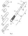
- Figures 1 to 4 show a first embodiment of an intramedullary nail which consists of a solid nail core 10 with a head 1 and a tip 2 and a longitudinal axis 3.
- a tread 9 is provided in the proximal section 4 adjacent to the head 1 .
- the middle section 13 of the core 10 has smooth surface and a tapering diameter towards the distal section 6 adjacent to the tip 2.
- the middle section 13 of the core 10 - with a minor diameter - and the end section 11 of the core 10 - with a larger diameter - are separated by an annular abutment 12.
- the nail expands - as shown in Fig. 4 - at a first radially expandable section 5 in the proximal section 4 adjacent to the head 1 of the nail and in a second radially expandable section 7 in the distal section 6 adjacent to the tip 2 of the nail.
- two hexagon sockets may be placed.
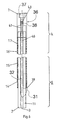
- Fig. 5 and 6 show an embodiment of the intramedullary nail which differentiates from the embodiment shown in Fig. 1-4 therein that it provides instead of the core 10 a hollow cylindrical sleeve 35 extending along the longitudinal axis 3 and surrounding a locking element 32 coaxially to the longitudinal axis 3.
- the locking element 32 comprises a shaft with a thread 41 in the proximal section 4 and in the distal section 6 a projection 31 forming an abutment 39.
- the sleeve 35 provides a slot 34 penetrating the side wall through to the bore 33 such that the projection 31 of the locking element 32 may slide within said slot 34 in the direction of the longitudinal axis 3.
- the following elements are slid over the sleeve 35 in the following sequence:
Abstract
Description
- a slotted tubular piece
- an unslotted tubular piece
- a slotted tubular piece
- an unslotted tubular piece
- a slotted
tubular piece 14 - an unslotted
tubular piece 15 - a slotted
tubular piece 16 - an unslotted
tubular piece 17 - a
nut 18 with an inner thread corresponding withthread 9.
- a slotted
tubular piece 14 - an unslotted
tubular piece 15 - a slotted
tubular piece 16 - an unslotted
tubular piece 17 - an
end cap 42 - a
nut 40 with an inner thread corresponding withthread 41.
Claims (11)
- Intramedullary nail for fixation of bone fractures with a head (1), a tip (2) and a longitudinal axis (3), comprisingA) a first radially expandable section (5) is provided in the proximal section (4) adjacent to the head (1) of the intramedullary nail;B) a second radially expandable section (7) is provided in the distal section (6) adjacent to the tip (2) of the intramedullary nail;C) a non-expandable middle section (8) is provided between said two radially expandable sections (5,7) of the intramedullary nail, wherebyD) the radially expandable sections (5;7) are realised by slotted tubular pieces (14;16); andE) the non-expandable middle section (8) is realised by a unslotted tubular piece (15),
characterised in thatF) the intramedullary nail comprises a hollow cylindrical sleeve (35) extending along the longitudinal axis (3); andG) a locking element (32) being surrounded by the sleeve (35); wherebyH) the locking element (32) comprises a shaft with a thread (41) in the proximal section (4) and a projection (31) forming an abutment (39) in the distal section (6); andI) the distal section (6) of the sleeve (35) is provided with a slot (34) penetrating the side wall through to the bore (33) such that the projection (31) of the locking element (32) may slide within said slot (34) in the direction of the longitudinal axis (3). - Intramedullary nail according to claim 1, characterized in that the head (1) is provided with a distraction mechanism (24), by means of which said two radially expandable sections (5,7) are distractible transverse to said longitudinal axis (3).
- Intramedullary nail according to claim 1 or 2, characterized in that said non-expandable section (8) of the intramedullary nail has a length in the range of 10 to 25 mm.
- Intramedullary nail according to claim 3, characterized in that said non-expandable section (8) of the intramedullary nail has a length in the range of 15 to 22 mm.
- Intramedullary nail according to one of the claims 1 to 4, characterized in that the slotted tubular pieces (14;16) are configured slidable on the sleeve (35) and prevented from sliding on the end section (11) towards the tip (2) by means of the abutment (39).
- Intramedullary nail according to one of the claims 2 to 5, characterized in that the distraction mechanism (24) comprises a thread (41) on the locking element (32) adjacent to the head (1) and a nut (40) with an interior thread corresponding with thread (41).
- Intramedullary nail according to claim 6, characterized in that the nut (40) comprises means (25) for engagement of a driving means.
- Intramedullary nail according to claim 6 or 7, characterized in that the locking element (32) comprises means (43) for engagement of a holding means.
- Intramedullary nail according to one of the claims 2 to 8, characterized in that the distraction mechanism (24) comprises a thread (41) on the locking element (32) adjacent to the head (1) and an end cap (36) with an interior thread (38) corresponding with thread (41).
- Intramedullary nail according to claim 9, characterized in that the end cap (36) comprises means (37) for engagement of a driving means.
- Intramedullary nail according to claim 9 or 10, characterized in that the locking element (32) comprises means (43) for engagement of a holding means.
Applications Claiming Priority (1)
| Application Number | Priority Date | Filing Date | Title |
|---|---|---|---|
| PCT/CH1999/000532 WO2001034045A1 (en) | 1999-11-11 | 1999-11-11 | Radially expandable intramedullary nail |
Publications (2)
| Publication Number | Publication Date |
|---|---|
| EP1227765A1 EP1227765A1 (en) | 2002-08-07 |
| EP1227765B1 true EP1227765B1 (en) | 2005-05-04 |
Family
ID=4551732
Family Applications (1)
| Application Number | Title | Priority Date | Filing Date |
|---|---|---|---|
| EP99952216A Expired - Lifetime EP1227765B1 (en) | 1999-11-11 | 1999-11-11 | Radially expandable intramedullary nail |
Country Status (9)
| Country | Link |
|---|---|
| US (1) | US6736818B2 (en) |
| EP (1) | EP1227765B1 (en) |
| JP (1) | JP4156839B2 (en) |
| AT (1) | ATE294538T1 (en) |
| AU (1) | AU774717B2 (en) |
| CA (1) | CA2391062C (en) |
| DE (1) | DE69925169T2 (en) |
| ES (1) | ES2241331T3 (en) |
| WO (1) | WO2001034045A1 (en) |
Cited By (7)
| Publication number | Priority date | Publication date | Assignee | Title |
|---|---|---|---|---|
| US8287538B2 (en) | 2008-01-14 | 2012-10-16 | Conventus Orthopaedics, Inc. | Apparatus and methods for fracture repair |
| US8906022B2 (en) | 2010-03-08 | 2014-12-09 | Conventus Orthopaedics, Inc. | Apparatus and methods for securing a bone implant |
| US8961518B2 (en) | 2010-01-20 | 2015-02-24 | Conventus Orthopaedics, Inc. | Apparatus and methods for bone access and cavity preparation |
| EP2910209A1 (en) | 2014-02-21 | 2015-08-26 | NG Patentverwertungs UG | Intramedullary device for osteosynthesis |
| US9730739B2 (en) | 2010-01-15 | 2017-08-15 | Conventus Orthopaedics, Inc. | Rotary-rigid orthopaedic rod |
| US10022132B2 (en) | 2013-12-12 | 2018-07-17 | Conventus Orthopaedics, Inc. | Tissue displacement tools and methods |
| US10918426B2 (en) | 2017-07-04 | 2021-02-16 | Conventus Orthopaedics, Inc. | Apparatus and methods for treatment of a bone |
Families Citing this family (197)
| Publication number | Priority date | Publication date | Assignee | Title |
|---|---|---|---|---|
| US7306628B2 (en) | 2002-10-29 | 2007-12-11 | St. Francis Medical Technologies | Interspinous process apparatus and method with a selectably expandable spacer |
| US20080086212A1 (en) | 1997-01-02 | 2008-04-10 | St. Francis Medical Technologies, Inc. | Spine distraction implant |
| US7959652B2 (en) * | 2005-04-18 | 2011-06-14 | Kyphon Sarl | Interspinous process implant having deployable wings and method of implantation |
| US6695842B2 (en) * | 1997-10-27 | 2004-02-24 | St. Francis Medical Technologies, Inc. | Interspinous process distraction system and method with positionable wing and method |
| US8128661B2 (en) * | 1997-01-02 | 2012-03-06 | Kyphon Sarl | Interspinous process distraction system and method with positionable wing and method |
| US7201751B2 (en) * | 1997-01-02 | 2007-04-10 | St. Francis Medical Technologies, Inc. | Supplemental spine fixation device |
| US20080215058A1 (en) * | 1997-01-02 | 2008-09-04 | Zucherman James F | Spine distraction implant and method |
| US6068630A (en) | 1997-01-02 | 2000-05-30 | St. Francis Medical Technologies, Inc. | Spine distraction implant |
| RU2296526C2 (en) * | 1998-10-26 | 2007-04-10 | Икспэндинг Ортопедикс Инк. | Expandable orthopedic device |
| US6554833B2 (en) | 1998-10-26 | 2003-04-29 | Expanding Orthopedics, Inc. | Expandable orthopedic device |
| US6261289B1 (en) * | 1998-10-26 | 2001-07-17 | Mark Levy | Expandable orthopedic device |
| US7485119B2 (en) * | 2000-03-07 | 2009-02-03 | Zimmer Technology, Inc. | Method and apparatus for reducing femoral fractures |
| US6527775B1 (en) * | 2000-09-22 | 2003-03-04 | Piper Medical, Inc. | Intramedullary interlocking fixation device for the distal radius |
| GB0102141D0 (en) * | 2001-01-27 | 2001-03-14 | Davies John B C | Improvements in or relating to expandable bone nails |
| AU2002354914B2 (en) * | 2001-07-16 | 2008-04-03 | Expanding Orthopedics Inc. | Expandable orthopedic device |
| FR2828398B1 (en) * | 2001-08-08 | 2003-09-19 | Jean Taylor | VERTEBRA STABILIZATION ASSEMBLY |
| FR2844179B1 (en) * | 2002-09-10 | 2004-12-03 | Jean Taylor | POSTERIOR VERTEBRAL SUPPORT KIT |
| US7549999B2 (en) | 2003-05-22 | 2009-06-23 | Kyphon Sarl | Interspinous process distraction implant and method of implantation |
| US8147548B2 (en) | 2005-03-21 | 2012-04-03 | Kyphon Sarl | Interspinous process implant having a thread-shaped wing and method of implantation |
| US20080021468A1 (en) | 2002-10-29 | 2008-01-24 | Zucherman James F | Interspinous process implants and methods of use |
| US8070778B2 (en) | 2003-05-22 | 2011-12-06 | Kyphon Sarl | Interspinous process implant with slide-in distraction piece and method of implantation |
| US8048117B2 (en) | 2003-05-22 | 2011-11-01 | Kyphon Sarl | Interspinous process implant and method of implantation |
| US7931674B2 (en) * | 2005-03-21 | 2011-04-26 | Kyphon Sarl | Interspinous process implant having deployable wing and method of implantation |
| US20050075637A1 (en) * | 2003-04-04 | 2005-04-07 | Semet Elliot Charles | Interlocking IM nails with outer screw |
| FR2857250B1 (en) * | 2003-07-09 | 2006-10-20 | Ortho I D | TELESCOPIC HUMERUS NAIL AUTOSTABLE |
| US7780667B2 (en) | 2003-09-08 | 2010-08-24 | Smith & Nephew, Inc. | Orthopaedic plate and screw assembly |
| US20050055024A1 (en) | 2003-09-08 | 2005-03-10 | James Anthony H. | Orthopaedic implant and screw assembly |
| US7799030B2 (en) | 2003-09-08 | 2010-09-21 | Smith & Nephew, Inc. | Orthopaedic plate and screw assembly |
| AU2003285364A1 (en) * | 2003-11-25 | 2005-06-24 | Javier Ara Pinilla | Intramedullary nail |
| US7828802B2 (en) | 2004-01-16 | 2010-11-09 | Expanding Orthopedics, Inc. | Bone fracture treatment devices and methods of their use |
| US8029548B2 (en) | 2008-05-05 | 2011-10-04 | Warsaw Orthopedic, Inc. | Flexible spinal stabilization element and system |
| US7799053B2 (en) * | 2004-03-08 | 2010-09-21 | Warsaw Orthopedic, Inc. | Occipital and cervical stabilization systems and methods |
| US7632277B2 (en) * | 2004-03-29 | 2009-12-15 | Woll Bioorthopedics Llc | Orthopedic intramedullary fixation system |
| WO2005094705A2 (en) * | 2004-03-31 | 2005-10-13 | Orthofix S.R.L | Shape memory alloy comprising intramedullary nail provided with expansion fixing means |
| EP1582161A1 (en) * | 2004-03-31 | 2005-10-05 | Orthofix International B.V. | Intramedullary nail provided with expansion fixing means operated by one or more driving elements |
| US7507241B2 (en) * | 2004-04-05 | 2009-03-24 | Expanding Orthopedics Inc. | Expandable bone device |
| CN1984613B (en) * | 2004-05-19 | 2010-09-29 | 欣蒂生物技术股份公司 | Intravertebral widening device |
| US7585316B2 (en) * | 2004-05-21 | 2009-09-08 | Warsaw Orthopedic, Inc. | Interspinous spacer |
| JP2008500140A (en) * | 2004-05-21 | 2008-01-10 | メイヤーズ サージカル ソリューションズ, エルエルシー | Fracture fixation and site stabilization system |
| US7481841B2 (en) * | 2004-06-30 | 2009-01-27 | Depuy Products, Inc. | Adjustable orthopaedic prosthesis and associated method |
| US7588577B2 (en) * | 2004-07-15 | 2009-09-15 | Wright Medical Technology, Inc. | Guide assembly for intramedullary fixation and method of using the same |
| US20060015101A1 (en) * | 2004-07-15 | 2006-01-19 | Wright Medical Technology, Inc. | Intramedullary fixation assembly and devices and methods for installing the same |
| WO2006034436A2 (en) | 2004-09-21 | 2006-03-30 | Stout Medical Group, L.P. | Expandable support device and method of use |
| US7559951B2 (en) * | 2004-09-30 | 2009-07-14 | Depuy Products, Inc. | Adjustable, remote-controllable orthopaedic prosthesis and associated method |
| US7857832B2 (en) * | 2004-12-08 | 2010-12-28 | Interventional Spine, Inc. | Method and apparatus for spinal stabilization |
| US7998174B2 (en) | 2005-02-17 | 2011-08-16 | Kyphon Sarl | Percutaneous spinal implants and methods |
| US20080039944A1 (en) * | 2005-02-17 | 2008-02-14 | Malandain Hugues F | Percutaneous Spinal Implants and Methods |
| US8038698B2 (en) * | 2005-02-17 | 2011-10-18 | Kphon Sarl | Percutaneous spinal implants and methods |
| US20060184248A1 (en) * | 2005-02-17 | 2006-08-17 | Edidin Avram A | Percutaneous spinal implants and methods |
| US8100943B2 (en) | 2005-02-17 | 2012-01-24 | Kyphon Sarl | Percutaneous spinal implants and methods |
| US8007521B2 (en) | 2005-02-17 | 2011-08-30 | Kyphon Sarl | Percutaneous spinal implants and methods |
| US8096994B2 (en) | 2005-02-17 | 2012-01-17 | Kyphon Sarl | Percutaneous spinal implants and methods |
| US7988709B2 (en) * | 2005-02-17 | 2011-08-02 | Kyphon Sarl | Percutaneous spinal implants and methods |
| US20070276372A1 (en) * | 2005-02-17 | 2007-11-29 | Malandain Hugues F | Percutaneous Spinal Implants and Methods |
| US8034080B2 (en) | 2005-02-17 | 2011-10-11 | Kyphon Sarl | Percutaneous spinal implants and methods |
| US8029567B2 (en) | 2005-02-17 | 2011-10-04 | Kyphon Sarl | Percutaneous spinal implants and methods |
| US20070276493A1 (en) | 2005-02-17 | 2007-11-29 | Malandain Hugues F | Percutaneous spinal implants and methods |
| US8157841B2 (en) | 2005-02-17 | 2012-04-17 | Kyphon Sarl | Percutaneous spinal implants and methods |
| US8097018B2 (en) | 2005-02-17 | 2012-01-17 | Kyphon Sarl | Percutaneous spinal implants and methods |
| US20080288078A1 (en) * | 2005-02-17 | 2008-11-20 | Kohm Andrew C | Percutaneous spinal implants and methods |
| US20070055237A1 (en) * | 2005-02-17 | 2007-03-08 | Edidin Avram A | Percutaneous spinal implants and methods |
| US8057513B2 (en) | 2005-02-17 | 2011-11-15 | Kyphon Sarl | Percutaneous spinal implants and methods |
| US20060241757A1 (en) * | 2005-03-31 | 2006-10-26 | Sdgi Holdings, Inc. | Intervertebral prosthetic device for spinal stabilization and method of manufacturing same |
| US8034079B2 (en) * | 2005-04-12 | 2011-10-11 | Warsaw Orthopedic, Inc. | Implants and methods for posterior dynamic stabilization of a spinal motion segment |
| FR2884406B1 (en) | 2005-04-14 | 2008-10-17 | Memometal Technologies Soc Par | INTRAMEDULAR OSTEOSYNTHESIS DEVICE OF TWO BONE PARTS, IN PARTICULAR HAND AND / OR FOOT |
| US7727233B2 (en) | 2005-04-29 | 2010-06-01 | Warsaw Orthopedic, Inc. | Spinous process stabilization devices and methods |
| WO2006124764A1 (en) | 2005-05-18 | 2006-11-23 | Sonoma Orthopedic Products, Inc. | Minimally invasive actuable bone fixation devices, systems and methods of use |
| US8961516B2 (en) | 2005-05-18 | 2015-02-24 | Sonoma Orthopedic Products, Inc. | Straight intramedullary fracture fixation devices and methods |
| US9060820B2 (en) | 2005-05-18 | 2015-06-23 | Sonoma Orthopedic Products, Inc. | Segmented intramedullary fracture fixation devices and methods |
| FR2887434B1 (en) | 2005-06-28 | 2008-03-28 | Jean Taylor | SURGICAL TREATMENT EQUIPMENT OF TWO VERTEBRATES |
| IL176810A (en) * | 2005-07-12 | 2011-02-28 | Intramed Systems Ltd | Intramedullar distraction device with user actuated distraction |
| EP1757243B1 (en) | 2005-08-24 | 2008-05-28 | BIEDERMANN MOTECH GmbH | Rod-shaped implant element for the application in spine surgery or trauma surgery and stabilization device with such a rod-shaped implant element |
| US20070049938A1 (en) * | 2005-08-31 | 2007-03-01 | Wallace Matthew S | Intramedullary nail assembly with locking component, locking component and nail for use therewith |
| US8998923B2 (en) | 2005-08-31 | 2015-04-07 | Spinealign Medical, Inc. | Threaded bone filling material plunger |
| US8357181B2 (en) * | 2005-10-27 | 2013-01-22 | Warsaw Orthopedic, Inc. | Intervertebral prosthetic device for spinal stabilization and method of implanting same |
| AU2006318673A1 (en) * | 2005-11-18 | 2007-05-31 | Life Spine, Inc. | Dynamic spinal stabilization devices and systems |
| US20070173823A1 (en) | 2006-01-18 | 2007-07-26 | Sdgi Holdings, Inc. | Intervertebral prosthetic device for spinal stabilization and method of implanting same |
| US8083795B2 (en) | 2006-01-18 | 2011-12-27 | Warsaw Orthopedic, Inc. | Intervertebral prosthetic device for spinal stabilization and method of manufacturing same |
| US7682376B2 (en) | 2006-01-27 | 2010-03-23 | Warsaw Orthopedic, Inc. | Interspinous devices and methods of use |
| US20070191838A1 (en) * | 2006-01-27 | 2007-08-16 | Sdgi Holdings, Inc. | Interspinous devices and methods of use |
| US7691130B2 (en) | 2006-01-27 | 2010-04-06 | Warsaw Orthopedic, Inc. | Spinal implants including a sensor and methods of use |
| US8262698B2 (en) | 2006-03-16 | 2012-09-11 | Warsaw Orthopedic, Inc. | Expandable device for insertion between anatomical structures and a procedure utilizing same |
| FR2899788B1 (en) * | 2006-04-13 | 2008-07-04 | Jean Taylor | TREATMENT EQUIPMENT FOR VERTEBRATES, COMPRISING AN INTEREPINOUS IMPLANT |
| US8118844B2 (en) | 2006-04-24 | 2012-02-21 | Warsaw Orthopedic, Inc. | Expandable device for insertion between anatomical structures and a procedure utilizing same |
| US7806900B2 (en) | 2006-04-26 | 2010-10-05 | Illuminoss Medical, Inc. | Apparatus and methods for delivery of reinforcing materials to bone |
| US8048118B2 (en) | 2006-04-28 | 2011-11-01 | Warsaw Orthopedic, Inc. | Adjustable interspinous process brace |
| WO2007131002A2 (en) | 2006-05-01 | 2007-11-15 | Stout Medical Group, L.P. | Expandable support device and method of use |
| US8062337B2 (en) * | 2006-05-04 | 2011-11-22 | Warsaw Orthopedic, Inc. | Expandable device for insertion between anatomical structures and a procedure utilizing same |
| US20070276496A1 (en) * | 2006-05-23 | 2007-11-29 | Sdgi Holdings, Inc. | Surgical spacer with shape control |
| US8147517B2 (en) * | 2006-05-23 | 2012-04-03 | Warsaw Orthopedic, Inc. | Systems and methods for adjusting properties of a spinal implant |
| US8048119B2 (en) | 2006-07-20 | 2011-11-01 | Warsaw Orthopedic, Inc. | Apparatus for insertion between anatomical structures and a procedure utilizing same |
| US8715283B2 (en) * | 2006-08-14 | 2014-05-06 | Smith & Nephew, Inc. | Fracture fixation device |
| US20090012564A1 (en) * | 2007-03-07 | 2009-01-08 | Spineworks Medical, Inc. | Transdiscal interbody fusion device and method |
| US20090005782A1 (en) | 2007-03-02 | 2009-01-01 | Chirico Paul E | Fracture Fixation System and Method |
| US20080086115A1 (en) * | 2006-09-07 | 2008-04-10 | Warsaw Orthopedic, Inc. | Intercostal spacer device and method for use in correcting a spinal deformity |
| US8097019B2 (en) | 2006-10-24 | 2012-01-17 | Kyphon Sarl | Systems and methods for in situ assembly of an interspinous process distraction implant |
| FR2908035B1 (en) | 2006-11-08 | 2009-05-01 | Jean Taylor | INTEREPINE IMPLANT |
| US7879041B2 (en) | 2006-11-10 | 2011-02-01 | Illuminoss Medical, Inc. | Systems and methods for internal bone fixation |
| US7811284B2 (en) | 2006-11-10 | 2010-10-12 | Illuminoss Medical, Inc. | Systems and methods for internal bone fixation |
| US7879104B2 (en) * | 2006-11-15 | 2011-02-01 | Warsaw Orthopedic, Inc. | Spinal implant system |
| CA2670263A1 (en) | 2006-11-22 | 2008-05-29 | Sonoma Orthopedic Products, Inc. | Fracture fixation device, tools and methods |
| US7955392B2 (en) | 2006-12-14 | 2011-06-07 | Warsaw Orthopedic, Inc. | Interspinous process devices and methods |
| US8961522B2 (en) * | 2007-01-25 | 2015-02-24 | Biomet C.V. | Flexible shaft reduction tool |
| US8109975B2 (en) * | 2007-01-30 | 2012-02-07 | Warsaw Orthopedic, Inc. | Collar bore configuration for dynamic spinal stabilization assembly |
| WO2008109872A2 (en) * | 2007-03-07 | 2008-09-12 | Spinealign Medical, Inc. | Systems, methods, and devices for soft tissue attachment to bone |
| WO2008112308A1 (en) * | 2007-03-12 | 2008-09-18 | Stout Medical Group, L.P. | Expandable attachment device and method |
| FR2913876B1 (en) | 2007-03-20 | 2009-06-05 | Memometal Technologies Soc Par | OSTEOSYNTHESIS DEVICE |
| US7918853B2 (en) | 2007-03-20 | 2011-04-05 | Smith & Nephew, Inc. | Orthopaedic plate and screw assembly |
| US8430879B2 (en) * | 2007-03-22 | 2013-04-30 | Sonoma Orthopedic Products, Inc. | Segmented intramedullary structure |
| US8128626B2 (en) * | 2007-04-24 | 2012-03-06 | Flexfix, Llc | System and method for delivery conformation and removal of intramedullary bone fixation devices |
| EP2155089A1 (en) * | 2007-05-08 | 2010-02-24 | Spineworks Medical, Inc. | Systems, devices and methods for stabilizing bone |
| WO2009005851A1 (en) * | 2007-06-29 | 2009-01-08 | Spinealign Medical, Inc. | Methods and devices for stabilizing bone compatible for use with bone screws |
| WO2009004603A2 (en) * | 2007-07-03 | 2009-01-08 | Sota Orthopaedics Limited | A bolt apparatus |
| US8172879B2 (en) | 2007-08-23 | 2012-05-08 | Life Spine, Inc. | Resilient spinal rod system with controllable angulation |
| WO2009059090A1 (en) | 2007-10-31 | 2009-05-07 | Illuminoss Medical, Inc. | Light source |
| EP2205162B1 (en) * | 2007-11-02 | 2015-09-09 | Stout Medical Group LP | Expandable attachment device |
| US8556949B2 (en) | 2007-11-14 | 2013-10-15 | DePuy Synthes Products, LLC | Hybrid bone fixation element and methods of using the same |
| US8771283B2 (en) | 2007-12-17 | 2014-07-08 | Wright Medical Technology, Inc. | Guide assembly for intramedullary fixation and method of using the same |
| US20090198241A1 (en) * | 2008-02-04 | 2009-08-06 | Phan Christopher U | Spine distraction tools and methods of use |
| US8105358B2 (en) | 2008-02-04 | 2012-01-31 | Kyphon Sarl | Medical implants and methods |
| US8491583B2 (en) * | 2008-02-27 | 2013-07-23 | Medshape, Inc. | Intramedullary medical device and methods of use and manufacture |
| US8114136B2 (en) | 2008-03-18 | 2012-02-14 | Warsaw Orthopedic, Inc. | Implants and methods for inter-spinous process dynamic stabilization of a spinal motion segment |
| WO2009152273A1 (en) | 2008-06-10 | 2009-12-17 | Sonoma Orthopedic Products, Inc. | Fracture fixation device, tools and methods |
| US8328807B2 (en) | 2008-07-09 | 2012-12-11 | Icon Orthopaedic Concepts, Llc | Ankle arthrodesis nail and outrigger assembly |
| US8414584B2 (en) | 2008-07-09 | 2013-04-09 | Icon Orthopaedic Concepts, Llc | Ankle arthrodesis nail and outrigger assembly |
| US20100030549A1 (en) * | 2008-07-31 | 2010-02-04 | Lee Michael M | Mobile device having human language translation capability with positional feedback |
| CA2738478A1 (en) | 2008-09-26 | 2010-04-01 | Sonoma Orthopedic Products, Inc. | Bone fixation device, tools and methods |
| US20100100135A1 (en) * | 2008-10-21 | 2010-04-22 | Phan Christopher U | Bone fixation device having an expandable anchor |
| US8114131B2 (en) | 2008-11-05 | 2012-02-14 | Kyphon Sarl | Extension limiting devices and methods of use for the spine |
| WO2010056895A1 (en) | 2008-11-12 | 2010-05-20 | Stout Medical Group, L.P. | Fixation device and method |
| US20100217330A1 (en) * | 2009-02-24 | 2010-08-26 | Phan Christopher U | Bone fixation devices and methods |
| CN102413777B (en) * | 2009-03-12 | 2014-07-16 | 扩张整形外科公司 | Bone implantation and stabilization assembly including deployment device |
| US8734497B2 (en) * | 2009-03-13 | 2014-05-27 | The University Of Toledo | Removable anchoring pedicle screw |
| US8012155B2 (en) * | 2009-04-02 | 2011-09-06 | Zimmer, Inc. | Apparatus and method for prophylactic hip fixation |
| US8372117B2 (en) * | 2009-06-05 | 2013-02-12 | Kyphon Sarl | Multi-level interspinous implants and methods of use |
| US8157842B2 (en) | 2009-06-12 | 2012-04-17 | Kyphon Sarl | Interspinous implant and methods of use |
| FR2947170B1 (en) * | 2009-06-24 | 2011-07-22 | Jean Marc Guichet | ELONGATION NUTS FOR LONG OR SIMILAR BONES |
| DE202010009097U1 (en) | 2009-06-25 | 2010-09-02 | Universität Duisburg-Essen | Mark Nagel |
| CA2765376C (en) | 2009-06-30 | 2017-06-06 | Smith & Nephew, Inc. | Orthopaedic implant and fastener assembly |
| WO2011038315A1 (en) * | 2009-09-28 | 2011-03-31 | Zimmer, Inc. | Expandable intramedullary rod |
| US8771317B2 (en) * | 2009-10-28 | 2014-07-08 | Warsaw Orthopedic, Inc. | Interspinous process implant and method of implantation |
| US8114132B2 (en) | 2010-01-13 | 2012-02-14 | Kyphon Sarl | Dynamic interspinous process device |
| US8317831B2 (en) * | 2010-01-13 | 2012-11-27 | Kyphon Sarl | Interspinous process spacer diagnostic balloon catheter and methods of use |
| US8147526B2 (en) | 2010-02-26 | 2012-04-03 | Kyphon Sarl | Interspinous process spacer diagnostic parallel balloon catheter and methods of use |
| US8617160B2 (en) | 2010-03-09 | 2013-12-31 | Torjo Medical Solutions, Inc. | Dynamic intramedullary hardware |
| US8685024B2 (en) | 2010-04-14 | 2014-04-01 | Arrowhead Medical Device Technologies, Llc | Intramedullary fixation device and methods for bone fixation and stabilization |
| US10349987B2 (en) | 2010-04-14 | 2019-07-16 | Arrowhead Medical Device Technologies, Llc | Intramedullary fixation devices |
| US9724140B2 (en) | 2010-06-02 | 2017-08-08 | Wright Medical Technology, Inc. | Tapered, cylindrical cruciform hammer toe implant and method |
| US8608785B2 (en) | 2010-06-02 | 2013-12-17 | Wright Medical Technology, Inc. | Hammer toe implant with expansion portion for retrograde approach |
| US9498273B2 (en) | 2010-06-02 | 2016-11-22 | Wright Medical Technology, Inc. | Orthopedic implant kit |
| WO2012010184A1 (en) * | 2010-07-22 | 2012-01-26 | Norman Zschech | Intramedullary nail |
| US8814908B2 (en) | 2010-07-26 | 2014-08-26 | Warsaw Orthopedic, Inc. | Injectable flexible interspinous process device system |
| US8663224B2 (en) | 2010-09-09 | 2014-03-04 | DePuy Synthes Products, LLC | Surgical nail |
| US8834483B2 (en) | 2010-10-04 | 2014-09-16 | Biomedical Enterprises, Inc. | Method and system for storing and inserting an implant |
| US9179959B2 (en) | 2010-12-22 | 2015-11-10 | Illuminoss Medical, Inc. | Systems and methods for treating conditions and diseases of the spine |
| US9138219B2 (en) | 2010-12-29 | 2015-09-22 | Tarsus Medical Inc. | Methods and devices for treating a syndesmosis injury |
| US8591548B2 (en) | 2011-03-31 | 2013-11-26 | Warsaw Orthopedic, Inc. | Spinous process fusion plate assembly |
| US8591549B2 (en) | 2011-04-08 | 2013-11-26 | Warsaw Orthopedic, Inc. | Variable durometer lumbar-sacral implant |
| US9028496B2 (en) | 2011-04-12 | 2015-05-12 | William L. Tontz | Device for establishing supportive forces in the bony structure of a skeleton |
| US9775661B2 (en) | 2011-07-19 | 2017-10-03 | Illuminoss Medical, Inc. | Devices and methods for bone restructure and stabilization |
| US8936644B2 (en) | 2011-07-19 | 2015-01-20 | Illuminoss Medical, Inc. | Systems and methods for joint stabilization |
| US8337495B1 (en) | 2011-08-16 | 2012-12-25 | Powlan Roy Y | Distal locking intramedullary nail |
| US9155578B2 (en) * | 2012-02-28 | 2015-10-13 | DePuy Synthes Products, Inc. | Expandable fastener |
| US10405903B1 (en) | 2012-05-04 | 2019-09-10 | Xtraverse, LLC | Fasteners with shape changing zigzag structures and methods using same |
| US8840612B2 (en) * | 2012-05-04 | 2014-09-23 | William L. Tontz | Intraosseous expandable fixation device |
| US9687281B2 (en) | 2012-12-20 | 2017-06-27 | Illuminoss Medical, Inc. | Distal tip for bone fixation devices |
| US8945232B2 (en) | 2012-12-31 | 2015-02-03 | Wright Medical Technology, Inc. | Ball and socket implants for correction of hammer toes and claw toes |
| EP2967688A4 (en) | 2013-03-13 | 2016-11-23 | Arrowhead Medical Device Technologies Llc | Hammertoe implant with asymmetrical head |
| US9452002B2 (en) | 2013-03-13 | 2016-09-27 | Arrowhead Medical Device Technologies, Llc | Hammertoe implant with enhanced gripping surfaces |
| WO2014159125A1 (en) | 2013-03-13 | 2014-10-02 | Arrowhead Medical Device Technologies Llc | Methods and implants for treating hammertoe and other deformities |
| US9724139B2 (en) | 2013-10-01 | 2017-08-08 | Wright Medical Technology, Inc. | Hammer toe implant and method |
| US9522022B2 (en) | 2013-11-18 | 2016-12-20 | Biomedical Enterprises, Inc. | Method and appparatus for an intramedullary implant and method of implantation therefor |
| US9636155B2 (en) | 2013-11-18 | 2017-05-02 | Biomedical Enterprises, Inc. | Method and apparatus for an intramudullary implant and method of implantation thereof |
| US9474561B2 (en) | 2013-11-19 | 2016-10-25 | Wright Medical Technology, Inc. | Two-wire technique for installing hammertoe implant |
| US9770278B2 (en) | 2014-01-17 | 2017-09-26 | Arthrex, Inc. | Dual tip guide wire |
| US9545274B2 (en) * | 2014-02-12 | 2017-01-17 | Wright Medical Technology, Inc. | Intramedullary implant, system, and method for inserting an implant into a bone |
| US9498266B2 (en) | 2014-02-12 | 2016-11-22 | Wright Medical Technology, Inc. | Intramedullary implant, system, and method for inserting an implant into a bone |
| KR101624614B1 (en) | 2014-07-18 | 2016-05-27 | 주식회사 케이씨스 | Shrinkage or expansion possible functional intramedullary fixation apparatus |
| US9808296B2 (en) | 2014-09-18 | 2017-11-07 | Wright Medical Technology, Inc. | Hammertoe implant and instrument |
| US9814499B2 (en) | 2014-09-30 | 2017-11-14 | Arthrex, Inc. | Intramedullary fracture fixation devices and methods |
| US10080597B2 (en) | 2014-12-19 | 2018-09-25 | Wright Medical Technology, Inc. | Intramedullary anchor for interphalangeal arthrodesis |
| KR101861421B1 (en) | 2015-01-14 | 2018-07-02 | 김두만 | A structure with a variable diameter |
| WO2016114558A1 (en) * | 2015-01-14 | 2016-07-21 | 주식회사 케이씨스 | Structure having variable diameter |
| US9757168B2 (en) | 2015-03-03 | 2017-09-12 | Howmedica Osteonics Corp. | Orthopedic implant and methods of implanting and removing same |
| US9907585B2 (en) | 2015-04-30 | 2018-03-06 | William Casey Fox | Bone intramedullary fixation scaffold |
| CN105105835B (en) * | 2015-09-26 | 2023-11-03 | 赵全明 | Intramedullary nail with locking mechanism |
| US10561449B2 (en) * | 2015-10-21 | 2020-02-18 | Tst Rakor Ve Tibbi Aletler Sanayi Ve Ticaret Limited Sirketi | Humerus internal safe locking nail |
| US9974581B2 (en) | 2015-11-20 | 2018-05-22 | Globus Medical, Inc. | Expandable intramedullary systems and methods of using the same |
| US9827025B2 (en) | 2015-11-20 | 2017-11-28 | Globus Medical, Inc. | Expandable intramedullary systems and methods of using the same |
| US10111691B2 (en) | 2015-11-20 | 2018-10-30 | Globus Medical, Inc. | Expandable intramedullary systems and methods of using the same |
| US10813673B2 (en) * | 2016-09-08 | 2020-10-27 | Meduloc, Llc | Implant and method for long bone fixation |
| EP3694430A1 (en) | 2017-10-11 | 2020-08-19 | Tornier, Inc. | Humeral fixation plate guides |
| US10888363B2 (en) | 2017-12-06 | 2021-01-12 | Stout Medical Group, L.P. | Attachment device and method for use |
| US11071572B2 (en) | 2018-06-27 | 2021-07-27 | Illuminoss Medical, Inc. | Systems and methods for bone stabilization and fixation |
| US11918261B2 (en) * | 2019-04-12 | 2024-03-05 | Stryker European Operations Limited | Locking system for femoral neck fracture fixation |
| DE102021112429A1 (en) | 2021-05-12 | 2022-11-17 | Roman Stauch | Intramedullary nail for transverse distraction |
| CN114145829B (en) * | 2021-12-08 | 2023-05-23 | 韩延明 | Intramedullary fixation system for absorbable material for tubular bone fracture |
Family Cites Families (50)
| Publication number | Priority date | Publication date | Assignee | Title |
|---|---|---|---|---|
| DE587317C (en) | 1932-02-13 | 1933-11-02 | Ernst Axel Johan Ericsson | Nail used to treat broken bones |
| US2834342A (en) | 1956-08-29 | 1958-05-13 | Clyde E Yost | Surgical device for the fixation of fractured bones |
| US3002514A (en) | 1958-01-24 | 1961-10-03 | Deyerle William Minor | Hip setting pin |
| US3025853A (en) | 1958-07-07 | 1962-03-20 | Christopher A Mason | Fixation device for fractured femur |
| US3029811A (en) | 1960-04-25 | 1962-04-17 | Ken Standard Corp | Surgical hip nail |
| US3561437A (en) | 1967-11-08 | 1971-02-09 | Jose Luis Orlich | Apparatus for fixing fractures of the femur |
| US4055172A (en) | 1973-07-18 | 1977-10-25 | Josef Ender | Nail and set for correctly resetting fractured bones for their immediate re-use |
| ES207117Y (en) * | 1974-10-25 | 1976-07-01 | Pares Avila | INTERNAL FIXING DEVICE FOR BONE FRACTURES. |
| DE2542263A1 (en) * | 1975-09-23 | 1977-03-24 | Christian Lassen | Osteo synthetic pin for bone fractures - has slotted ends which are expanded by screwed spindle |
| IL53703A (en) * | 1977-12-28 | 1979-10-31 | Aginsky Yacov | Intramedullary nails |
| US4262665A (en) * | 1979-06-27 | 1981-04-21 | Roalstad W L | Intramedullary compression device |
| US4503847A (en) | 1982-01-15 | 1985-03-12 | Howmedica, Inc. | Prosthetic nail |
| IT1156599B (en) | 1982-05-12 | 1987-02-04 | Oscar Scaglietti | ENDOMIDOLLAR NAIL FOR LONG BONES |
| FR2527921A1 (en) | 1982-06-02 | 1983-12-09 | Tornier Sa | IMPROVEMENTS IN THE NAILS FOR THE OSTEOSYNTHESIS OF THE FRACTURES OF FEMALE COLLARS |
| SU1071298A1 (en) | 1982-09-17 | 1984-02-07 | Koptyukh Vladimir V | Apparatus for osteosynthesis |
| JPS6017708U (en) | 1983-07-13 | 1985-02-06 | 宮田 敬三 | Metal fittings for intramedullary fixation of fractured long bones |
| US4628923A (en) | 1983-11-28 | 1986-12-16 | Medoff Robert J | Axial compression device |
| IL70736A (en) * | 1984-01-20 | 1988-05-31 | Rosenberg Lior | Self-locking pin device particularly useful for internally fixing bone fractures |
| SU1337074A1 (en) | 1985-06-21 | 1987-09-15 | В.В.Коптюх | Arrangement for osteosynthesis |
| RO89820B1 (en) | 1985-11-05 | 2002-06-28 | îNTREPRINDEREA INDUSTRIA TEHNICO MEDICALA | Elastic implants for a stable elastic osteorrhaphy of femoral and tibial fractures, respectively, as well as corresponding instrumentation |
| US4776330A (en) | 1986-06-23 | 1988-10-11 | Pfizer Hospital Products Group, Inc. | Modular femoral fixation system |
| DE8703491U1 (en) | 1987-03-09 | 1987-04-23 | Waldemar Link Gmbh & Co, 2000 Hamburg, De | |
| CH673762A5 (en) | 1987-12-02 | 1990-04-12 | Synthes Ag | |
| CH683963A5 (en) | 1988-06-10 | 1994-06-30 | Synthes Ag | Internal fixation. |
| FR2633345A1 (en) * | 1988-06-23 | 1989-12-29 | Ducharme Raymond | Assembly pin which is self-locking by means of expansion, and adjustable pulling-together loads, for surgical or other consolidation |
| DE3835682A1 (en) | 1988-10-20 | 1990-04-26 | Labitzke Reiner Prof Dr Med Ha | Device for stabilizing fractures of tubular bones and of joints |
| CN1046845A (en) | 1989-04-30 | 1990-11-14 | 张懋 | Fracture inside fixing Z type plate and synthetism method thereof |
| US5281225A (en) * | 1989-06-07 | 1994-01-25 | Guglielmo Vicenzi | Intramedullary pin with self-locking end for metadiaphyseal fractures of long bones |
| US4978349A (en) | 1989-08-03 | 1990-12-18 | Synthes (U.S.A.) | Fixation plate |
| US5034012A (en) | 1989-11-21 | 1991-07-23 | Synthes (U.S.A.) | Intramedullary nail with loop tip |
| US5032125A (en) | 1990-02-06 | 1991-07-16 | Smith & Nephew Richards Inc. | Intramedullary hip screw |
| CH681595A5 (en) | 1990-03-19 | 1993-04-30 | Synthes Ag | |
| US5053035A (en) | 1990-05-24 | 1991-10-01 | Mclaren Alexander C | Flexible intramedullary fixation rod |
| CH682300A5 (en) | 1990-12-17 | 1993-08-31 | Synthes Ag | |
| CH683024A5 (en) | 1991-04-16 | 1993-12-31 | Synthes Ag | Connecting means for connecting a first adjustable with a second construction element, in particular of tubes or rods of a fixation device. |
| CH685851A5 (en) | 1991-05-24 | 1995-10-31 | Synthes Ag | A surgical instrument for positioning osteosynthetic fasteners |
| CH686222A5 (en) | 1991-05-30 | 1996-02-15 | Synthes Ag | The trochanter stabilization. |
| US5443466A (en) | 1991-12-13 | 1995-08-22 | Shah; Mrugesh K. | Method and apparatus for treating fractures of a bone |
| EP0599847B1 (en) | 1992-06-25 | 1997-04-02 | Synthes AG, Chur | Osteosynthetic fixation device |
| GB2268068B (en) * | 1992-07-01 | 1996-08-21 | John Bruce Clayfield Davies | Devices having expansion means for securing end portions of tubular members |
| US5498264A (en) | 1992-07-21 | 1996-03-12 | Synthes (U.S.A.) | Clamp connection for connecting two construction components for a setting device, particularly an osteosynthetic setting device |
| US5433718A (en) | 1992-08-20 | 1995-07-18 | Brinker; Mark | Antibiotic eluding intramedullary nail apparatus |
| US5437666A (en) | 1992-08-24 | 1995-08-01 | Synthes (U.S.A.) | External fixation device for osteosynthesis |
| WO1994026190A1 (en) | 1993-05-11 | 1994-11-24 | Synthes Ag Chur | Osteo-synthetic securing component and manipulation aid therefor |
| FR2711505B1 (en) | 1993-10-25 | 1995-12-29 | Tornier Sa | Device for synthesizing fractures of the upper end of the femur. |
| US5514137A (en) | 1993-12-06 | 1996-05-07 | Coutts; Richard D. | Fixation of orthopedic devices |
| FR2741256A1 (en) * | 1995-11-21 | 1997-05-23 | Advanced Technical Fabrication | CENTROMEDULAR NAIL |
| US6187007B1 (en) | 1996-07-31 | 2001-02-13 | Synthes (Usa) | Device for attaching fractured hip-joint heads |
| ES2183018T3 (en) | 1996-12-02 | 2003-03-16 | Synthes Ag | FLAT INTRAMEDULAR KEY. |
| US5741256A (en) | 1997-01-13 | 1998-04-21 | Synthes (U.S.A.) | Helical osteosynthetic implant |
-
1999
- 1999-11-11 AU AU64581/99A patent/AU774717B2/en not_active Ceased
- 1999-11-11 JP JP2001536056A patent/JP4156839B2/en not_active Expired - Fee Related
- 1999-11-11 DE DE69925169T patent/DE69925169T2/en not_active Expired - Lifetime
- 1999-11-11 ES ES99952216T patent/ES2241331T3/en not_active Expired - Lifetime
- 1999-11-11 AT AT99952216T patent/ATE294538T1/en not_active IP Right Cessation
- 1999-11-11 CA CA002391062A patent/CA2391062C/en not_active Expired - Fee Related
- 1999-11-11 WO PCT/CH1999/000532 patent/WO2001034045A1/en active IP Right Grant
- 1999-11-11 EP EP99952216A patent/EP1227765B1/en not_active Expired - Lifetime
-
2002
- 2002-05-10 US US10/141,835 patent/US6736818B2/en not_active Expired - Fee Related
Cited By (12)
| Publication number | Priority date | Publication date | Assignee | Title |
|---|---|---|---|---|
| US8287538B2 (en) | 2008-01-14 | 2012-10-16 | Conventus Orthopaedics, Inc. | Apparatus and methods for fracture repair |
| US9517093B2 (en) | 2008-01-14 | 2016-12-13 | Conventus Orthopaedics, Inc. | Apparatus and methods for fracture repair |
| US9788870B2 (en) | 2008-01-14 | 2017-10-17 | Conventus Orthopaedics, Inc. | Apparatus and methods for fracture repair |
| US9730739B2 (en) | 2010-01-15 | 2017-08-15 | Conventus Orthopaedics, Inc. | Rotary-rigid orthopaedic rod |
| US8961518B2 (en) | 2010-01-20 | 2015-02-24 | Conventus Orthopaedics, Inc. | Apparatus and methods for bone access and cavity preparation |
| US9848889B2 (en) | 2010-01-20 | 2017-12-26 | Conventus Orthopaedics, Inc. | Apparatus and methods for bone access and cavity preparation |
| US8906022B2 (en) | 2010-03-08 | 2014-12-09 | Conventus Orthopaedics, Inc. | Apparatus and methods for securing a bone implant |
| US9993277B2 (en) | 2010-03-08 | 2018-06-12 | Conventus Orthopaedics, Inc. | Apparatus and methods for securing a bone implant |
| US10022132B2 (en) | 2013-12-12 | 2018-07-17 | Conventus Orthopaedics, Inc. | Tissue displacement tools and methods |
| US10076342B2 (en) | 2013-12-12 | 2018-09-18 | Conventus Orthopaedics, Inc. | Tissue displacement tools and methods |
| EP2910209A1 (en) | 2014-02-21 | 2015-08-26 | NG Patentverwertungs UG | Intramedullary device for osteosynthesis |
| US10918426B2 (en) | 2017-07-04 | 2021-02-16 | Conventus Orthopaedics, Inc. | Apparatus and methods for treatment of a bone |
Also Published As
| Publication number | Publication date |
|---|---|
| ATE294538T1 (en) | 2005-05-15 |
| JP4156839B2 (en) | 2008-09-24 |
| US20020165544A1 (en) | 2002-11-07 |
| AU6458199A (en) | 2001-06-06 |
| DE69925169D1 (en) | 2005-06-09 |
| JP2003513698A (en) | 2003-04-15 |
| CA2391062C (en) | 2008-01-08 |
| DE69925169T2 (en) | 2006-02-23 |
| ES2241331T3 (en) | 2005-10-16 |
| CA2391062A1 (en) | 2001-05-17 |
| WO2001034045A1 (en) | 2001-05-17 |
| EP1227765A1 (en) | 2002-08-07 |
| AU774717B2 (en) | 2004-07-08 |
| US6736818B2 (en) | 2004-05-18 |
Similar Documents
| Publication | Publication Date | Title |
|---|---|---|
| EP1227765B1 (en) | Radially expandable intramedullary nail | |
| EP0550814B1 (en) | Anchorage nail for the treatment of hollow bone fractures | |
| EP1363545B1 (en) | Improvements in or relating to expandable bone nails | |
| US4227518A (en) | Intramedullary retraction nail for fixation of comminuted fractured bones | |
| JP2549805B2 (en) | Bone nails for medical repair of radius fractures | |
| JP2671975B2 (en) | Device to stabilize long bones | |
| EP2175790B1 (en) | A bolt apparatus | |
| KR101926352B1 (en) | Trochanteric femoral nail augmentable | |
| US8080040B2 (en) | Anchor with two member securing mechanism for attaching an elongated member to a bone | |
| US6575973B1 (en) | Self locking intramedullary nail | |
| EP2448504B1 (en) | Intramedullary nail and protruding screw locking mechanism | |
| JP6453767B2 (en) | Automatic lengthening implant | |
| JP2004513757A (en) | Fixation device for fixing bones, especially vertebral bodies, relative to each other | |
| WO2002034120A2 (en) | Facet fixation devices | |
| CA2516791A1 (en) | Adjustable rod and connector device and method of use | |
| JP2019516467A (en) | Medical device for temporarily fastening multiaxial pedicle screws | |
| HU226853B1 (en) | Disposable external fixation device | |
| CA2500864A1 (en) | Device for fixing bones | |
| HU219634B (en) | Securing element for osteosynthesis | |
| EP2910209A1 (en) | Intramedullary device for osteosynthesis | |
| EP3372178B1 (en) | External fixator assembly | |
| US8470005B1 (en) | Hip nail support assembly | |
| JPH09313502A (en) | Fixing device for bone | |
| AU2002225210A1 (en) | Improvements in or relating to expandable bone nails | |
| NZ518670A (en) | Radially expandable intramedullary nail |
Legal Events
| Date | Code | Title | Description |
|---|---|---|---|
| PUAI | Public reference made under article 153(3) epc to a published international application that has entered the european phase |
Free format text: ORIGINAL CODE: 0009012 |
|
| 17P | Request for examination filed |
Effective date: 20020420 |
|
| AK | Designated contracting states |
Kind code of ref document: A1 Designated state(s): AT BE CH CY DE DK ES FI FR GB GR IE IT LI LU MC NL PT SE |
|
| 17Q | First examination report despatched |
Effective date: 20030515 |
|
| GRAP | Despatch of communication of intention to grant a patent |
Free format text: ORIGINAL CODE: EPIDOSNIGR1 |
|
| GRAS | Grant fee paid |
Free format text: ORIGINAL CODE: EPIDOSNIGR3 |
|
| GRAA | (expected) grant |
Free format text: ORIGINAL CODE: 0009210 |
|
| AK | Designated contracting states |
Kind code of ref document: B1 Designated state(s): AT BE CH CY DE DK ES FI FR GB GR IE IT LI LU MC NL PT SE |
|
| PG25 | Lapsed in a contracting state [announced via postgrant information from national office to epo] |
Ref country code: FI Free format text: LAPSE BECAUSE OF FAILURE TO SUBMIT A TRANSLATION OF THE DESCRIPTION OR TO PAY THE FEE WITHIN THE PRESCRIBED TIME-LIMIT Effective date: 20050504 Ref country code: BE Free format text: LAPSE BECAUSE OF FAILURE TO SUBMIT A TRANSLATION OF THE DESCRIPTION OR TO PAY THE FEE WITHIN THE PRESCRIBED TIME-LIMIT Effective date: 20050504 |
|
| REG | Reference to a national code |
Ref country code: GB Ref legal event code: FG4D |
|
| REG | Reference to a national code |
Ref country code: CH Ref legal event code: NV Representative=s name: DR. LUSUARDI AG Ref country code: CH Ref legal event code: EP |
|
| REG | Reference to a national code |
Ref country code: IE Ref legal event code: FG4D |
|
| REF | Corresponds to: |
Ref document number: 69925169 Country of ref document: DE Date of ref document: 20050609 Kind code of ref document: P |
|
| PG25 | Lapsed in a contracting state [announced via postgrant information from national office to epo] |
Ref country code: SE Free format text: LAPSE BECAUSE OF FAILURE TO SUBMIT A TRANSLATION OF THE DESCRIPTION OR TO PAY THE FEE WITHIN THE PRESCRIBED TIME-LIMIT Effective date: 20050804 Ref country code: GR Free format text: LAPSE BECAUSE OF FAILURE TO SUBMIT A TRANSLATION OF THE DESCRIPTION OR TO PAY THE FEE WITHIN THE PRESCRIBED TIME-LIMIT Effective date: 20050804 Ref country code: DK Free format text: LAPSE BECAUSE OF FAILURE TO SUBMIT A TRANSLATION OF THE DESCRIPTION OR TO PAY THE FEE WITHIN THE PRESCRIBED TIME-LIMIT Effective date: 20050804 |
|
| REG | Reference to a national code |
Ref country code: ES Ref legal event code: FG2A Ref document number: 2241331 Country of ref document: ES Kind code of ref document: T3 |
|
| PG25 | Lapsed in a contracting state [announced via postgrant information from national office to epo] |
Ref country code: PT Free format text: LAPSE BECAUSE OF FAILURE TO SUBMIT A TRANSLATION OF THE DESCRIPTION OR TO PAY THE FEE WITHIN THE PRESCRIBED TIME-LIMIT Effective date: 20051017 |
|
| PGFP | Annual fee paid to national office [announced via postgrant information from national office to epo] |
Ref country code: NL Payment date: 20051018 Year of fee payment: 7 |
|
| PG25 | Lapsed in a contracting state [announced via postgrant information from national office to epo] |
Ref country code: IE Free format text: LAPSE BECAUSE OF NON-PAYMENT OF DUE FEES Effective date: 20051111 Ref country code: CY Free format text: LAPSE BECAUSE OF FAILURE TO SUBMIT A TRANSLATION OF THE DESCRIPTION OR TO PAY THE FEE WITHIN THE PRESCRIBED TIME-LIMIT Effective date: 20051111 |
|
| PG25 | Lapsed in a contracting state [announced via postgrant information from national office to epo] |
Ref country code: MC Free format text: LAPSE BECAUSE OF NON-PAYMENT OF DUE FEES Effective date: 20051130 Ref country code: LU Free format text: LAPSE BECAUSE OF NON-PAYMENT OF DUE FEES Effective date: 20051130 |
|
| PLBE | No opposition filed within time limit |
Free format text: ORIGINAL CODE: 0009261 |
|
| STAA | Information on the status of an ep patent application or granted ep patent |
Free format text: STATUS: NO OPPOSITION FILED WITHIN TIME LIMIT |
|
| 26N | No opposition filed |
Effective date: 20060207 |
|
| EN | Fr: translation not filed | ||
| REG | Reference to a national code |
Ref country code: IE Ref legal event code: MM4A |
|
| REG | Reference to a national code |
Ref country code: CH Ref legal event code: PUE Owner name: SYNTHES GMBH Free format text: SYNTHES AG CHUR#GRABENSTRASSE 15#7002 CHUR (CH) -TRANSFER TO- SYNTHES GMBH#EIMATTSTRASSE 3#4436 OBERDORF (CH) |
|
| REG | Reference to a national code |
Ref country code: GB Ref legal event code: 732E |
|
| NLS | Nl: assignments of ep-patents |
Owner name: SYNTHES GMBH Effective date: 20061030 |
|
| PG25 | Lapsed in a contracting state [announced via postgrant information from national office to epo] |
Ref country code: NL Free format text: LAPSE BECAUSE OF NON-PAYMENT OF DUE FEES Effective date: 20070601 |
|
| NLV4 | Nl: lapsed or anulled due to non-payment of the annual fee |
Effective date: 20070601 |
|
| PG25 | Lapsed in a contracting state [announced via postgrant information from national office to epo] |
Ref country code: FR Free format text: LAPSE BECAUSE OF NON-PAYMENT OF DUE FEES Effective date: 20051130 |
|
| PG25 | Lapsed in a contracting state [announced via postgrant information from national office to epo] |
Ref country code: FR Free format text: LAPSE BECAUSE OF NON-PAYMENT OF DUE FEES Effective date: 20050504 |
|
| PGFP | Annual fee paid to national office [announced via postgrant information from national office to epo] |
Ref country code: ES Payment date: 20091201 Year of fee payment: 11 Ref country code: AT Payment date: 20091111 Year of fee payment: 11 |
|
| PG25 | Lapsed in a contracting state [announced via postgrant information from national office to epo] |
Ref country code: AT Free format text: LAPSE BECAUSE OF NON-PAYMENT OF DUE FEES Effective date: 20101111 |
|
| REG | Reference to a national code |
Ref country code: ES Ref legal event code: FD2A Effective date: 20120220 |
|
| PG25 | Lapsed in a contracting state [announced via postgrant information from national office to epo] |
Ref country code: ES Free format text: LAPSE BECAUSE OF NON-PAYMENT OF DUE FEES Effective date: 20101112 |
|
| PGFP | Annual fee paid to national office [announced via postgrant information from national office to epo] |
Ref country code: GB Payment date: 20131106 Year of fee payment: 15 Ref country code: DE Payment date: 20131106 Year of fee payment: 15 Ref country code: CH Payment date: 20131112 Year of fee payment: 15 |
|
| PGFP | Annual fee paid to national office [announced via postgrant information from national office to epo] |
Ref country code: IT Payment date: 20131114 Year of fee payment: 15 |
|
| REG | Reference to a national code |
Ref country code: DE Ref legal event code: R119 Ref document number: 69925169 Country of ref document: DE |
|
| REG | Reference to a national code |
Ref country code: CH Ref legal event code: PL |
|
| GBPC | Gb: european patent ceased through non-payment of renewal fee |
Effective date: 20141111 |
|
| PG25 | Lapsed in a contracting state [announced via postgrant information from national office to epo] |
Ref country code: CH Free format text: LAPSE BECAUSE OF NON-PAYMENT OF DUE FEES Effective date: 20141130 Ref country code: LI Free format text: LAPSE BECAUSE OF NON-PAYMENT OF DUE FEES Effective date: 20141130 |
|
| PG25 | Lapsed in a contracting state [announced via postgrant information from national office to epo] |
Ref country code: DE Free format text: LAPSE BECAUSE OF NON-PAYMENT OF DUE FEES Effective date: 20150602 Ref country code: GB Free format text: LAPSE BECAUSE OF NON-PAYMENT OF DUE FEES Effective date: 20141111 |
|
| PG25 | Lapsed in a contracting state [announced via postgrant information from national office to epo] |
Ref country code: IT Free format text: LAPSE BECAUSE OF NON-PAYMENT OF DUE FEES Effective date: 20141111 |