EP1232910A2 - Vehicle light - Google Patents
Vehicle light Download PDFInfo
- Publication number
- EP1232910A2 EP1232910A2 EP02003330A EP02003330A EP1232910A2 EP 1232910 A2 EP1232910 A2 EP 1232910A2 EP 02003330 A EP02003330 A EP 02003330A EP 02003330 A EP02003330 A EP 02003330A EP 1232910 A2 EP1232910 A2 EP 1232910A2
- Authority
- EP
- European Patent Office
- Prior art keywords
- light
- reflector
- vehicle lamp
- lamp according
- housing
- Prior art date
- Legal status (The legal status is an assumption and is not a legal conclusion. Google has not performed a legal analysis and makes no representation as to the accuracy of the status listed.)
- Granted
Links
Images
Classifications
-
- B—PERFORMING OPERATIONS; TRANSPORTING
- B60—VEHICLES IN GENERAL
- B60Q—ARRANGEMENT OF SIGNALLING OR LIGHTING DEVICES, THE MOUNTING OR SUPPORTING THEREOF OR CIRCUITS THEREFOR, FOR VEHICLES IN GENERAL
- B60Q1/00—Arrangement of optical signalling or lighting devices, the mounting or supporting thereof or circuits therefor
- B60Q1/26—Arrangement of optical signalling or lighting devices, the mounting or supporting thereof or circuits therefor the devices being primarily intended to indicate the vehicle, or parts thereof, or to give signals, to other traffic
- B60Q1/2696—Mounting of devices using LEDs
-
- F—MECHANICAL ENGINEERING; LIGHTING; HEATING; WEAPONS; BLASTING
- F21—LIGHTING
- F21S—NON-PORTABLE LIGHTING DEVICES; SYSTEMS THEREOF; VEHICLE LIGHTING DEVICES SPECIALLY ADAPTED FOR VEHICLE EXTERIORS
- F21S43/00—Signalling devices specially adapted for vehicle exteriors, e.g. brake lamps, direction indicator lights or reversing lights
- F21S43/10—Signalling devices specially adapted for vehicle exteriors, e.g. brake lamps, direction indicator lights or reversing lights characterised by the light source
- F21S43/13—Signalling devices specially adapted for vehicle exteriors, e.g. brake lamps, direction indicator lights or reversing lights characterised by the light source characterised by the type of light source
- F21S43/14—Light emitting diodes [LED]
-
- F—MECHANICAL ENGINEERING; LIGHTING; HEATING; WEAPONS; BLASTING
- F21—LIGHTING
- F21S—NON-PORTABLE LIGHTING DEVICES; SYSTEMS THEREOF; VEHICLE LIGHTING DEVICES SPECIALLY ADAPTED FOR VEHICLE EXTERIORS
- F21S43/00—Signalling devices specially adapted for vehicle exteriors, e.g. brake lamps, direction indicator lights or reversing lights
- F21S43/10—Signalling devices specially adapted for vehicle exteriors, e.g. brake lamps, direction indicator lights or reversing lights characterised by the light source
- F21S43/13—Signalling devices specially adapted for vehicle exteriors, e.g. brake lamps, direction indicator lights or reversing lights characterised by the light source characterised by the type of light source
- F21S43/15—Strips of light sources
-
- F—MECHANICAL ENGINEERING; LIGHTING; HEATING; WEAPONS; BLASTING
- F21—LIGHTING
- F21S—NON-PORTABLE LIGHTING DEVICES; SYSTEMS THEREOF; VEHICLE LIGHTING DEVICES SPECIALLY ADAPTED FOR VEHICLE EXTERIORS
- F21S43/00—Signalling devices specially adapted for vehicle exteriors, e.g. brake lamps, direction indicator lights or reversing lights
- F21S43/30—Signalling devices specially adapted for vehicle exteriors, e.g. brake lamps, direction indicator lights or reversing lights characterised by reflectors
- F21S43/31—Optical layout thereof
Definitions
- the invention relates to a vehicle lamp, in particular a raised brake light for Motor vehicles of the type described in claim 1.
- Such lights are known for example from DE-OS 196 47 094.
- the disadvantage is these known arrangements that the light exit disc is optically effective Structure must have the required or desired distribution of the from the To achieve luminaire emerging light. This doesn't meet modern requirements, that aim for a design that is as clear as possible, that the technical structures of such a Luminaire can be recognized.
- the invention is therefore based on the object of a vehicle lamp of the type mentioned To create a style that meets modern design requirements and still do it enables the light emerging from the luminaire to be selected according to legal requirements to mark the corresponding distribution.
- the invention provides the features set out in claim 1 in front.
- the luminaire according to the invention receives a design that meets modern design requirements Appearance, since one looks from the outside in particular against the radiation direction Look into the light and recognize the reflecting reflector arrangement inside it can.
- the reflecting surfaces of the individual reflectors follow this arrangement Although essentially a partially parabolic envelope surface, there are a large number of sub-areas or facets tilted against this envelope surface, their number, size and tilt or inclination in space can be varied within wide limits to achieve the desired or required light distribution.
- the light-emitting diodes 2 are of a high-pitched type according to the invention Brake light 1 mounted on a common circuit board 3, which in the in Fig. 1st reproduced installation position against the horizontal upwards and backwards, d. H. opposite the radiation direction shown by the arrows F inclined in a substantially in cross section rectangular, trough-like housing 5 made of opaque material so installed is that the light-emitting area 6 of the light-emitting diodes 2 is just below the upper edge 7 of the housing 5 is located.
- a partially parabolic reflector 8 is mounted so that it is reflective Surface 9 protrudes upwards from the housing. Because of this arrangement is that of the respective light-emitting diode 2 is radiated into the reflector 8 obliquely from below Light emitted essentially in the horizontal direction (arrows F). So the LEDs are 2 not immediately visible when looking from behind, i.e. H. against the direction of Arrows F looks at the brake light 1 according to the invention.
- FIG. 1 is approximately triangular in cross section of FIG. 1 on the housing 5 translucent material placed, the right part in Fig. 1, the light exit disc 12 of the brake light 1 according to the invention forms.
- this light exit disk 12 as an optically inactive component is formed and has no influence on the distribution of the emerging from the brake light 1 Light takes.
- this task is performed by the reflectors 8, of which, according to FIG. which shows only half the arrangement, sixteen arranged side by side and in one piece are interconnected. 2, the reflecting surface is one each reflector 8 divided into a multitude of facets that oppose a partial parabola forming envelope are individually tilted to achieve a desired light distribution.
Abstract
Description
Die Erfindung betrifft eine Fahrzeugleuchte, insbesondere hochgesetzte Bremsleuchte für Kraftfahrzeuge der im Anspruch 1 beschriebenen Art.The invention relates to a vehicle lamp, in particular a raised brake light for Motor vehicles of the type described in claim 1.
Solche Leuchten sind beispielsweise aus der DE-OS 196 47 094 bekannt. Nachteilig ist an diesen bekannten Anordnungen, daß die Lichtaustrittsscheibe eine optisch wirksame Struktur aufweisen muß, um die erforderliche bzw. gewünschte Verteilung des aus der Leuchte austretenden Lichtes zu erzielen. Dies entspricht nicht den modernen Anforderungen, die auf ein möglichst klares Design abzielen, das die technischen Strukturen einer solchen Leuchte erkennen läßt.Such lights are known for example from DE-OS 196 47 094. The disadvantage is these known arrangements that the light exit disc is optically effective Structure must have the required or desired distribution of the from the To achieve luminaire emerging light. This doesn't meet modern requirements, that aim for a design that is as clear as possible, that the technical structures of such a Luminaire can be recognized.
Somit liegt der Erfindung die Aufgabe zugrunde, eine Fahrzeugleuchte der eingangs genannten Art zu schaffen, die modernen Design-Anforderungen entspricht und es dennoch ermöglicht, dem aus der Leuchte austretenden Licht eine wählbare, den gesetzlichen Anforderungen entsprechende Verteilung aufzuprägen.The invention is therefore based on the object of a vehicle lamp of the type mentioned To create a style that meets modern design requirements and still do it enables the light emerging from the luminaire to be selected according to legal requirements to mark the corresponding distribution.
Zur Lösung dieser Aufgabe sieht die Erfindung die im Anspruch 1 niedergelegten Merkmale vor.To achieve this object, the invention provides the features set out in claim 1 in front.
Dadurch, daß die Lichtaustrittsscheibe als optisch inaktives Bauelement ausgebildet ist, das die Lichtverteilung des aus der Leuchte austretenden Lichtes in keiner Weise beeinflußt, erhält die erfindungsgemäße Leuchte ein den modernen Design-Anforderungen entsprechendes Aussehen, da man von außen insbesondere entgegen der Abstrahlrichtung in die Leuchte hinein blicken und die in ihr befindliche, spiegelnde Reflektoranordnung erkennen kann. Die reflektierenden Oberflächen der einzelnen Reflektoren dieser Anordnung folgen zwar im wesentlichen einer teilparabolischen Hüllfläche, sind jedoch in eine Vielzahl von gegen diese Hüllfläche verkippten Teilflächen bzw. Facetten unterteilt, deren Anzahl, Größe und Verkippung bzw. Neigung im Raum innerhalb weiter Grenzen variiert werden kann, um die jeweils gewünschte bzw. erforderliche Lichtverteilung zu erzielen.Characterized in that the light exit disc is designed as an optically inactive component, the in no way influences the light distribution of the light emerging from the luminaire, the luminaire according to the invention receives a design that meets modern design requirements Appearance, since one looks from the outside in particular against the radiation direction Look into the light and recognize the reflecting reflector arrangement inside it can. The reflecting surfaces of the individual reflectors follow this arrangement Although essentially a partially parabolic envelope surface, there are a large number of sub-areas or facets tilted against this envelope surface, their number, size and tilt or inclination in space can be varied within wide limits to achieve the desired or required light distribution.
Weitere vorteilhafte Ausgestaltungen einer erfindungsgemäßen Fahrzeugleuchte sind in den Unteransprüchen niedergelegt.Further advantageous configurations of a vehicle lamp according to the invention are shown in the subordinate claims.
Die Erfindung wird im folgenden anhand eines Ausführungsbeispiels unter Bezugnahme auf die Zeichnung beschrieben ; in dieser zeigen:
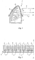
- Fig. 1
- eine schematische Schnittansicht durch eine erfindungsgemäße Fahrzeugleuchte und
- Fig. 2
- eine entgegen der Abstrahlrichtung gesehene Darstellung der an der Linie A-A halbierten Leuchtdioden- und Reflektoranordnung der Fahrzeugleuchte aus Fig. 1.
- Fig. 1
- is a schematic sectional view through a vehicle lamp according to the invention and
- Fig. 2
- FIG. 2 shows an illustration of the light-emitting diode and reflector arrangement of the vehicle lamp from FIG. 1 that is halved on the line AA.
Wie man der Fig. 1 entnimmt, sind die Leuchtdioden 2 einer erfindungsgemäßen, hochgesetzten
Bremsleuchte 1 auf einer gemeinsamen Leiterplatte 3 montiert, die in der in Fig. 1
wiedergegebenen Einbaulage gegen die Horizontale nach oben und hinten, d. h. entgegen
der durch die Pfeile F dargestellten Abstrahlrichtung geneigt in ein im Querschnitt im wesentlichen
rechteckiges, trogartiges Gehäuse 5 aus lichtundurchlässigem Material so eingebaut
ist, daß sich der Licht emittierende Bereich 6 der Leuchtdioden 2 knapp unterhalb
der Oberkante 7 des Gehäuses 5 befindet.As can be seen from FIG. 1, the light-emitting
Im Gehäuse 5 ist ein teilparabolischer Reflektor 8 so montiert, daß er mit seiner reflektierenden
Fläche 9 aus dem Gehäuse nach oben heraus ragt. Aufgrund dieser Anordnung
wird das von der jeweiligen Leuchtdiode 2 von schräg unten in den Reflektor 8 eingestrahlte
Licht im wesentlichen in horizontaler Richtung (Pfeile F) abgestrahlt. Somit sind die Leuchtdioden
2 nicht unmittelbar sichtbar, wenn man von hinten, d. h. entgegen der Richtung der
Pfeile F auf die erfindungsgemäße Bremsleuchte 1 blickt.In the
Auf das Gehäuse 5 ist eine im Querschnitt der Fig. 1 in etwa dreieckige Haube 11 aus
lichtdurchlässigem Material aufgesetzt, deren in Fig. 1 rechter Teil die Lichtaustrittsscheibe
12 der erfindungsgemäßen Bremsleuchte 1 bildet.1 is approximately triangular in cross section of FIG. 1 on the
Wesentlich ist dabei, daß diese Lichtaustrittsscheibe 12 als optisch inaktives Bauelement
ausgebildet ist und keinerlei Einfluß auf die Verteilung des aus der Bremsleuchte 1 austretenden
Lichtes nimmt.It is essential that this
Diese Aufgabe übernehmen erfindungsgemäß die Reflektoren 8, von denen gemäß Fig. 2,
welche nur die halbe Anordnung zeigt, sechzehn nebeneinander angeordnet und einstückig
miteinander verbunden sind. Wie man der Fig. 2 entnimmt, ist die reflektierende Fläche eines
jeden Reflektors 8 in eine Vielzahl von Facetten unterteilt, die gegen die eine Teilparabel
bildende Hüllfläche individuell verkippt sind, um eine gewünschte Lichtverteilung zu erzielen.According to the invention, this task is performed by the
Claims (6)
Applications Claiming Priority (2)
| Application Number | Priority Date | Filing Date | Title |
|---|---|---|---|
| DE20102587U | 2001-02-14 | ||
| DE20102587U DE20102587U1 (en) | 2001-02-14 | 2001-02-14 | Vehicle light |
Publications (3)
| Publication Number | Publication Date |
|---|---|
| EP1232910A2 true EP1232910A2 (en) | 2002-08-21 |
| EP1232910A3 EP1232910A3 (en) | 2004-04-14 |
| EP1232910B1 EP1232910B1 (en) | 2010-11-10 |
Family
ID=7952974
Family Applications (1)
| Application Number | Title | Priority Date | Filing Date |
|---|---|---|---|
| EP02003330A Expired - Lifetime EP1232910B1 (en) | 2001-02-14 | 2002-02-13 | Vehicle light |
Country Status (5)
| Country | Link |
|---|---|
| US (1) | US20020118548A1 (en) |
| EP (1) | EP1232910B1 (en) |
| AT (1) | ATE487641T1 (en) |
| DE (2) | DE20102587U1 (en) |
| ES (1) | ES2354684T3 (en) |
Cited By (2)
| Publication number | Priority date | Publication date | Assignee | Title |
|---|---|---|---|---|
| DE102007013082A1 (en) | 2007-03-14 | 2008-09-18 | Hella Kgaa Hueck & Co. | Signal light i.e. elevated brake light, for motor vehicle, has elongated reflection section including set of reflection elements and provided at rear side for deflecting coupled light in main radiation direction |
| CN108613124A (en) * | 2016-12-06 | 2018-10-02 | 丹阳市亚美车辆部件有限公司 | A kind of automobile-used LED is side steering indicating light installed |
Families Citing this family (32)
| Publication number | Priority date | Publication date | Assignee | Title |
|---|---|---|---|---|
| JP2003059313A (en) * | 2001-08-15 | 2003-02-28 | Koito Mfg Co Ltd | Vehicule lighting device |
| DE10215039A1 (en) * | 2002-04-05 | 2003-10-23 | Automotive Lighting Reutlingen | Day driving light, especially for motor vehicles, has light source with at least one LED and reflector for focusing light from source; LED(s) is built into optical system based on Cassegrain principle |
| DE10221683A1 (en) * | 2002-05-16 | 2003-12-04 | Hella Kg Hueck & Co | vehicle light |
| US6945672B2 (en) * | 2002-08-30 | 2005-09-20 | Gelcore Llc | LED planar light source and low-profile headlight constructed therewith |
| JP4002159B2 (en) * | 2002-09-03 | 2007-10-31 | 株式会社小糸製作所 | Vehicle headlamp |
| DE10247328B3 (en) * | 2002-10-10 | 2004-05-27 | Fer Fahrzeugelektrik Gmbh | Lighting especially for a motor vehicle has series of light uncoupling layers to successively deflect a light beam through an extended outlet surface |
| DE20219483U1 (en) * | 2002-12-16 | 2003-05-08 | Fer Fahrzeugelektrik Gmbh | vehicle light |
| US7188984B2 (en) | 2003-04-17 | 2007-03-13 | Visteon Global Technologies, Inc. | LED headlamp array |
| US6840661B2 (en) * | 2003-04-25 | 2005-01-11 | Gregg P. Desjardins | Flush fitting LED turn signal |
| AT500750B8 (en) * | 2003-06-06 | 2007-02-15 | Zizala Lichtsysteme Gmbh | VEHICLE HEADLIGHTS |
| JP4061251B2 (en) | 2003-08-05 | 2008-03-12 | 株式会社小糸製作所 | Vehicle lighting |
| DE10345567A1 (en) | 2003-09-29 | 2005-05-19 | Erco Leuchten Gmbh | Reflector luminaire, such as floor, ceiling or wall-mounted reflector luminaire, in particular stepped reflector luminaire |
| US8197110B2 (en) * | 2003-10-10 | 2012-06-12 | Federal Signal Corporation | Light assembly incorporating reflective features |
| ES2405759T3 (en) | 2003-10-10 | 2013-06-03 | Federal Signal Corporation | Light assembly |
| KR20070030273A (en) * | 2004-06-10 | 2007-03-15 | 터치센서 테크놀로지스, 엘엘씨 | Appliance convenience light |
| JP4413762B2 (en) * | 2004-12-07 | 2010-02-10 | 株式会社小糸製作所 | Lighting fixtures for vehicles |
| TWM291088U (en) * | 2005-12-08 | 2006-05-21 | Upec Electronics Corp | Illuminating device |
| JP4786420B2 (en) * | 2006-05-31 | 2011-10-05 | 株式会社小糸製作所 | Vehicle lamp unit |
| DE102007059607A1 (en) * | 2007-12-11 | 2009-06-18 | Bartenbach, Christian, Ing. | Wall and / or ceiling light |
| CN101566309A (en) * | 2008-04-23 | 2009-10-28 | 富准精密工业(深圳)有限公司 | Light-emitting diode illuminating device |
| US8292480B2 (en) | 2008-07-10 | 2012-10-23 | Koito Manufacturing Co., Ltd. | Lamp including main reflector, sub-reflector and LED assembly |
| CN102072446A (en) * | 2009-11-24 | 2011-05-25 | 深圳市安华信科技发展有限公司 | LED (Light Emitting Diode) vehicle turning auxiliary lamp |
| IT1402274B1 (en) * | 2010-07-30 | 2013-08-28 | Beghelli Spa | OPTICAL SYSTEM FOR THE HOMOGENEOUS SPREAD OF LIGHT EMITTED BY LIGHT SOURCES |
| DE102012202290B4 (en) * | 2012-02-15 | 2014-03-27 | Automotive Lighting Reutlingen Gmbh | Light module for a glare-free motor vehicle high beam |
| US9616811B2 (en) | 2012-07-10 | 2017-04-11 | Emergency Technology, Inc. | Emergency vehicle light fixture with reflective surface having alternating linear and revolved parabolic segments |
| JP6011260B2 (en) * | 2012-11-12 | 2016-10-19 | 市光工業株式会社 | Vehicle lighting |
| JP6363709B2 (en) * | 2013-08-08 | 2018-07-25 | コーニンクレッカ フィリップス エヌ ヴェKoninklijke Philips N.V. | General daytime running lamp for motor vehicles |
| JP2015088483A (en) * | 2013-09-26 | 2015-05-07 | 信越化学工業株式会社 | Red color lamp and light device for vehicle |
| EP3181994A4 (en) * | 2014-08-11 | 2018-07-25 | Koito Manufacturing Co., Ltd. | Vehicle headlight |
| CN104456357A (en) * | 2014-11-19 | 2015-03-25 | 江苏文光车辆附件有限公司 | Automobile LED light-emitting structure |
| US20170023208A1 (en) * | 2015-07-22 | 2017-01-26 | JST Performance, LLC | Method and apparatus for indirect lighting |
| DE102017208999A1 (en) * | 2017-05-29 | 2018-11-29 | Volkswagen Aktiengesellschaft | Illumination device for illuminating the interior of a motor vehicle |
Citations (1)
| Publication number | Priority date | Publication date | Assignee | Title |
|---|---|---|---|---|
| DE19647094A1 (en) | 1995-12-15 | 1997-06-19 | Valeo Vision | Rear brake light for motor vehicle |
Family Cites Families (4)
| Publication number | Priority date | Publication date | Assignee | Title |
|---|---|---|---|---|
| US3710095A (en) * | 1970-09-23 | 1973-01-09 | Gen Motors Corp | Method of making a faceted reflector for a lighting unit |
| US5471371A (en) * | 1993-01-08 | 1995-11-28 | Ford Motor Company | High efficiency illuminator |
| ES2165227T3 (en) * | 1999-08-11 | 2002-03-01 | Automotive Lighting Italia Spa | LIGHT FOR MOTOR VEHICLE. |
| DE20110842U1 (en) * | 2001-06-21 | 2001-11-08 | Ibf Ind Baugruppenfertigungs G | Brake light for motor vehicles |
-
2001
- 2001-02-14 DE DE20102587U patent/DE20102587U1/en not_active Expired - Lifetime
-
2002
- 2002-02-13 ES ES02003330T patent/ES2354684T3/en not_active Expired - Lifetime
- 2002-02-13 AT AT02003330T patent/ATE487641T1/en active
- 2002-02-13 DE DE50214755T patent/DE50214755D1/en not_active Expired - Lifetime
- 2002-02-13 EP EP02003330A patent/EP1232910B1/en not_active Expired - Lifetime
- 2002-02-14 US US10/074,691 patent/US20020118548A1/en not_active Abandoned
Patent Citations (1)
| Publication number | Priority date | Publication date | Assignee | Title |
|---|---|---|---|---|
| DE19647094A1 (en) | 1995-12-15 | 1997-06-19 | Valeo Vision | Rear brake light for motor vehicle |
Cited By (2)
| Publication number | Priority date | Publication date | Assignee | Title |
|---|---|---|---|---|
| DE102007013082A1 (en) | 2007-03-14 | 2008-09-18 | Hella Kgaa Hueck & Co. | Signal light i.e. elevated brake light, for motor vehicle, has elongated reflection section including set of reflection elements and provided at rear side for deflecting coupled light in main radiation direction |
| CN108613124A (en) * | 2016-12-06 | 2018-10-02 | 丹阳市亚美车辆部件有限公司 | A kind of automobile-used LED is side steering indicating light installed |
Also Published As
| Publication number | Publication date |
|---|---|
| US20020118548A1 (en) | 2002-08-29 |
| DE20102587U1 (en) | 2001-05-10 |
| ATE487641T1 (en) | 2010-11-15 |
| EP1232910B1 (en) | 2010-11-10 |
| DE50214755D1 (en) | 2010-12-23 |
| ES2354684T3 (en) | 2011-03-17 |
| EP1232910A3 (en) | 2004-04-14 |
Similar Documents
| Publication | Publication Date | Title |
|---|---|---|
| EP1232910B1 (en) | Vehicle light | |
| EP0780265B1 (en) | Vehicle rear light | |
| DE4417695C2 (en) | Motor vehicle light | |
| DE3542292A1 (en) | Luminaire for a motor vehicle | |
| EP1970250B1 (en) | Lamp for vehicles, in particular motor vehicles | |
| EP0999405A2 (en) | Signal light, in particular vehicle - preferably motor vehicle - tail light | |
| DE10207694A1 (en) | Lighting unit for motor vehicles has a casing with light-decoupling units fitted one behind the other in a light-exit direction | |
| EP2276969B1 (en) | Vehicle lamp | |
| DE19851374C2 (en) | Luminaire optics for a motor vehicle lamp | |
| EP1077344A2 (en) | Lamp | |
| EP1574779A1 (en) | Reflex reflector for tail-lights of vehicles | |
| DE19646042B4 (en) | Vehicle lighting device | |
| WO2018202582A1 (en) | Lighting device for vehicles | |
| DE102017105838A1 (en) | Lighting device of a motor vehicle with a light guide arrangement | |
| DE10144000B4 (en) | Vehicle headlight with several lighting devices | |
| EP1213531B1 (en) | Vehicle lamp | |
| DE102014212918A1 (en) | Motor vehicle lighting device | |
| DE102020107728A1 (en) | Lighting device for a vehicle | |
| DE102010020616A1 (en) | Lighting device for vehicle, has light elements arranged on rigid carrier plate, which is extended in given angle of inclination to side of housing, where each light element is assigned to deflecting reflector | |
| EP0684425A2 (en) | Luminaire comprising at least a light source | |
| EP1506104B1 (en) | Luminous unit, particularly as an additional light in sideview mirrors of motor vehicles | |
| DE102018220623A1 (en) | Lamp arrangement for a vehicle | |
| DE19838911B4 (en) | Lighting device of a vehicle | |
| DE10139812A1 (en) | Interior/courtesy light for motor vehicles has two luminous devices emitting light with different spectral distribution and a reflector for bundling the light from these luminous devices. | |
| DE102005042576A1 (en) | Lighting unit for motor vehicles |
Legal Events
| Date | Code | Title | Description |
|---|---|---|---|
| PUAI | Public reference made under article 153(3) epc to a published international application that has entered the european phase |
Free format text: ORIGINAL CODE: 0009012 |
|
| AK | Designated contracting states |
Kind code of ref document: A2 Designated state(s): AT BE CH CY DE DK ES FI FR GB GR IE IT LI LU MC NL PT SE TR |
|
| AX | Request for extension of the european patent |
Free format text: AL;LT;LV;MK;RO;SI |
|
| PUAL | Search report despatched |
Free format text: ORIGINAL CODE: 0009013 |
|
| AK | Designated contracting states |
Kind code of ref document: A3 Designated state(s): AT BE CH CY DE DK ES FI FR GB GR IE IT LI LU MC NL PT SE TR |
|
| AX | Request for extension of the european patent |
Extension state: AL LT LV MK RO SI |
|
| 17P | Request for examination filed |
Effective date: 20040319 |
|
| AKX | Designation fees paid |
Designated state(s): AT BE CH CY DE DK ES FI FR GB GR IE IT LI LU MC NL PT SE TR |
|
| 17Q | First examination report despatched |
Effective date: 20080610 |
|
| RAP1 | Party data changed (applicant data changed or rights of an application transferred) |
Owner name: TRUCK-LITE EUROPE GMBH |
|
| GRAP | Despatch of communication of intention to grant a patent |
Free format text: ORIGINAL CODE: EPIDOSNIGR1 |
|
| GRAS | Grant fee paid |
Free format text: ORIGINAL CODE: EPIDOSNIGR3 |
|
| GRAA | (expected) grant |
Free format text: ORIGINAL CODE: 0009210 |
|
| AK | Designated contracting states |
Kind code of ref document: B1 Designated state(s): AT BE CH CY DE DK ES FI FR GB GR IE IT LI LU MC NL PT SE TR |
|
| REG | Reference to a national code |
Ref country code: GB Ref legal event code: FG4D Free format text: NOT ENGLISH |
|
| REG | Reference to a national code |
Ref country code: CH Ref legal event code: EP |
|
| REG | Reference to a national code |
Ref country code: IE Ref legal event code: FG4D Free format text: LANGUAGE OF EP DOCUMENT: GERMAN |
|
| REF | Corresponds to: |
Ref document number: 50214755 Country of ref document: DE Date of ref document: 20101223 Kind code of ref document: P |
|
| REG | Reference to a national code |
Ref country code: NL Ref legal event code: VDEP Effective date: 20101110 |
|
| REG | Reference to a national code |
Ref country code: ES Ref legal event code: FG2A Effective date: 20110307 |
|
| PG25 | Lapsed in a contracting state [announced via postgrant information from national office to epo] |
Ref country code: NL Free format text: LAPSE BECAUSE OF FAILURE TO SUBMIT A TRANSLATION OF THE DESCRIPTION OR TO PAY THE FEE WITHIN THE PRESCRIBED TIME-LIMIT Effective date: 20101110 Ref country code: CY Free format text: LAPSE BECAUSE OF FAILURE TO SUBMIT A TRANSLATION OF THE DESCRIPTION OR TO PAY THE FEE WITHIN THE PRESCRIBED TIME-LIMIT Effective date: 20101110 Ref country code: SE Free format text: LAPSE BECAUSE OF FAILURE TO SUBMIT A TRANSLATION OF THE DESCRIPTION OR TO PAY THE FEE WITHIN THE PRESCRIBED TIME-LIMIT Effective date: 20101110 Ref country code: FI Free format text: LAPSE BECAUSE OF FAILURE TO SUBMIT A TRANSLATION OF THE DESCRIPTION OR TO PAY THE FEE WITHIN THE PRESCRIBED TIME-LIMIT Effective date: 20101110 Ref country code: PT Free format text: LAPSE BECAUSE OF FAILURE TO SUBMIT A TRANSLATION OF THE DESCRIPTION OR TO PAY THE FEE WITHIN THE PRESCRIBED TIME-LIMIT Effective date: 20110310 |
|
| REG | Reference to a national code |
Ref country code: IE Ref legal event code: FD4D |
|
| PG25 | Lapsed in a contracting state [announced via postgrant information from national office to epo] |
Ref country code: GR Free format text: LAPSE BECAUSE OF FAILURE TO SUBMIT A TRANSLATION OF THE DESCRIPTION OR TO PAY THE FEE WITHIN THE PRESCRIBED TIME-LIMIT Effective date: 20110211 |
|
| PG25 | Lapsed in a contracting state [announced via postgrant information from national office to epo] |
Ref country code: IE Free format text: LAPSE BECAUSE OF FAILURE TO SUBMIT A TRANSLATION OF THE DESCRIPTION OR TO PAY THE FEE WITHIN THE PRESCRIBED TIME-LIMIT Effective date: 20101110 |
|
| BERE | Be: lapsed |
Owner name: TRUCK-LITE EUROPE G.M.B.H. Effective date: 20110228 |
|
| PG25 | Lapsed in a contracting state [announced via postgrant information from national office to epo] |
Ref country code: DK Free format text: LAPSE BECAUSE OF FAILURE TO SUBMIT A TRANSLATION OF THE DESCRIPTION OR TO PAY THE FEE WITHIN THE PRESCRIBED TIME-LIMIT Effective date: 20101110 |
|
| PLBE | No opposition filed within time limit |
Free format text: ORIGINAL CODE: 0009261 |
|
| STAA | Information on the status of an ep patent application or granted ep patent |
Free format text: STATUS: NO OPPOSITION FILED WITHIN TIME LIMIT |
|
| PG25 | Lapsed in a contracting state [announced via postgrant information from national office to epo] |
Ref country code: MC Free format text: LAPSE BECAUSE OF NON-PAYMENT OF DUE FEES Effective date: 20110228 |
|
| REG | Reference to a national code |
Ref country code: CH Ref legal event code: PL |
|
| 26N | No opposition filed |
Effective date: 20110811 |
|
| GBPC | Gb: european patent ceased through non-payment of renewal fee |
Effective date: 20110213 |
|
| PG25 | Lapsed in a contracting state [announced via postgrant information from national office to epo] |
Ref country code: LI Free format text: LAPSE BECAUSE OF NON-PAYMENT OF DUE FEES Effective date: 20110228 Ref country code: CH Free format text: LAPSE BECAUSE OF NON-PAYMENT OF DUE FEES Effective date: 20110228 |
|
| PG25 | Lapsed in a contracting state [announced via postgrant information from national office to epo] |
Ref country code: BE Free format text: LAPSE BECAUSE OF NON-PAYMENT OF DUE FEES Effective date: 20110228 |
|
| REG | Reference to a national code |
Ref country code: DE Ref legal event code: R097 Ref document number: 50214755 Country of ref document: DE Effective date: 20110811 |
|
| PG25 | Lapsed in a contracting state [announced via postgrant information from national office to epo] |
Ref country code: GB Free format text: LAPSE BECAUSE OF NON-PAYMENT OF DUE FEES Effective date: 20110213 |
|
| PGFP | Annual fee paid to national office [announced via postgrant information from national office to epo] |
Ref country code: IT Payment date: 20120206 Year of fee payment: 11 |
|
| REG | Reference to a national code |
Ref country code: AT Ref legal event code: MM01 Ref document number: 487641 Country of ref document: AT Kind code of ref document: T Effective date: 20110213 |
|
| PG25 | Lapsed in a contracting state [announced via postgrant information from national office to epo] |
Ref country code: AT Free format text: LAPSE BECAUSE OF NON-PAYMENT OF DUE FEES Effective date: 20110213 |
|
| PGFP | Annual fee paid to national office [announced via postgrant information from national office to epo] |
Ref country code: ES Payment date: 20130218 Year of fee payment: 12 |
|
| PG25 | Lapsed in a contracting state [announced via postgrant information from national office to epo] |
Ref country code: LU Free format text: LAPSE BECAUSE OF NON-PAYMENT OF DUE FEES Effective date: 20110213 |
|
| PG25 | Lapsed in a contracting state [announced via postgrant information from national office to epo] |
Ref country code: TR Free format text: LAPSE BECAUSE OF FAILURE TO SUBMIT A TRANSLATION OF THE DESCRIPTION OR TO PAY THE FEE WITHIN THE PRESCRIBED TIME-LIMIT Effective date: 20101110 |
|
| REG | Reference to a national code |
Ref country code: FR Ref legal event code: PLFP Year of fee payment: 14 |
|
| REG | Reference to a national code |
Ref country code: ES Ref legal event code: FD2A Effective date: 20150505 |
|
| PG25 | Lapsed in a contracting state [announced via postgrant information from national office to epo] |
Ref country code: ES Free format text: LAPSE BECAUSE OF NON-PAYMENT OF DUE FEES Effective date: 20140214 |
|
| REG | Reference to a national code |
Ref country code: FR Ref legal event code: PLFP Year of fee payment: 15 |
|
| PG25 | Lapsed in a contracting state [announced via postgrant information from national office to epo] |
Ref country code: IT Free format text: LAPSE BECAUSE OF NON-PAYMENT OF DUE FEES Effective date: 20140213 |
|
| REG | Reference to a national code |
Ref country code: FR Ref legal event code: PLFP Year of fee payment: 16 |
|
| REG | Reference to a national code |
Ref country code: FR Ref legal event code: PLFP Year of fee payment: 17 |
|
| PGFP | Annual fee paid to national office [announced via postgrant information from national office to epo] |
Ref country code: FR Payment date: 20210217 Year of fee payment: 20 |
|
| PGFP | Annual fee paid to national office [announced via postgrant information from national office to epo] |
Ref country code: DE Payment date: 20210428 Year of fee payment: 20 |
|
| REG | Reference to a national code |
Ref country code: DE Ref legal event code: R071 Ref document number: 50214755 Country of ref document: DE |