EP1248384A1 - Transmit power control method - Google Patents
Transmit power control method Download PDFInfo
- Publication number
- EP1248384A1 EP1248384A1 EP01107740A EP01107740A EP1248384A1 EP 1248384 A1 EP1248384 A1 EP 1248384A1 EP 01107740 A EP01107740 A EP 01107740A EP 01107740 A EP01107740 A EP 01107740A EP 1248384 A1 EP1248384 A1 EP 1248384A1
- Authority
- EP
- European Patent Office
- Prior art keywords
- power
- range
- transmission
- amplifier
- information
- Prior art date
- Legal status (The legal status is an assumption and is not a legal conclusion. Google has not performed a legal analysis and makes no representation as to the accuracy of the status listed.)
- Granted
Links
Images


Classifications
-
- H—ELECTRICITY
- H04—ELECTRIC COMMUNICATION TECHNIQUE
- H04W—WIRELESS COMMUNICATION NETWORKS
- H04W52/00—Power management, e.g. TPC [Transmission Power Control], power saving or power classes
- H04W52/04—TPC
- H04W52/52—TPC using AGC [Automatic Gain Control] circuits or amplifiers
-
- H—ELECTRICITY
- H04—ELECTRIC COMMUNICATION TECHNIQUE
- H04W—WIRELESS COMMUNICATION NETWORKS
- H04W52/00—Power management, e.g. TPC [Transmission Power Control], power saving or power classes
- H04W52/04—TPC
- H04W52/18—TPC being performed according to specific parameters
- H04W52/22—TPC being performed according to specific parameters taking into account previous information or commands
- H04W52/226—TPC being performed according to specific parameters taking into account previous information or commands using past references to control power, e.g. look-up-table
-
- H—ELECTRICITY
- H04—ELECTRIC COMMUNICATION TECHNIQUE
- H04W—WIRELESS COMMUNICATION NETWORKS
- H04W52/00—Power management, e.g. TPC [Transmission Power Control], power saving or power classes
- H04W52/04—TPC
- H04W52/30—TPC using constraints in the total amount of available transmission power
- H04W52/36—TPC using constraints in the total amount of available transmission power with a discrete range or set of values, e.g. step size, ramping or offsets
- H04W52/367—Power values between minimum and maximum limits, e.g. dynamic range
-
- H—ELECTRICITY
- H04—ELECTRIC COMMUNICATION TECHNIQUE
- H04W—WIRELESS COMMUNICATION NETWORKS
- H04W52/00—Power management, e.g. TPC [Transmission Power Control], power saving or power classes
- H04W52/04—TPC
- H04W52/38—TPC being performed in particular situations
- H04W52/44—TPC being performed in particular situations in connection with interruption of transmission
Definitions
- the invention relates generally to wireless communication, especially those intended to operate according to the UMTS standard.
- a base station communicates with a plurality of remote terminals, such as cellular mobile phones.
- Multiple accesses by division of frequency FDMA: “Fréquency-Division Multiple Access” in language English
- TDMA time division Multiple Access
- FDMA Frequency-Division Multiple Access
- TDMA Time Division Multiple Access
- the basic idea behind FDMA and TDMA systems consists in sharing the available resource, respectively in several frequencies or in several intervals temporal, so that multiple terminals can operate simultaneously without causing interference.
- GSM standard phones belong to to FDMA and TDMA systems in that the transmission and reception takes place at different frequencies and also at different time intervals.
- CDMA systems In contrast to these systems using frequency division or a time division, CDMA systems (Access system multiples by code division; “Code Division Multiple Access” in English language) allow multiple users to share a common frequency and a common time channel using a coded modulation.
- CDMA systems one can cite the system CDMA 2000, the WCDMA system ("Wide Band CDMA" in language English; CDMA broadband) or IS-95.
- a scrambling code in English language is associated with each base station and allows distinguish one base station from another.
- a code orthogonal known to a person skilled in the art under the name of "OVSF code” is allocated to each remote terminal (as per cell phone). All OVSF codes are orthogonal to each other, which makes it possible to distinguish a remote terminal of another.
- the signal Before transmitting a signal on the transmission channel to destination of a remote terminal, the signal has been scrambled and spread ("spreaded" in English) by the base station using the base station scrambling code and terminal OVSF code remote.
- CDMA-FDD system a separate frequency for transmission and reception
- CDMA-TDD system a separate time domain for transmission and reception
- the invention advantageously applies to CDMA type communication, and more particularly to systems of the CDMA-FDD type.
- the invention also applies to FDMA and TDMA communication, in particular on telephones GSM and GPRS, and more generally at terminals operating according to the UMTS standard which must be able for example to operate at both under a CDMA system, like the WCDMA system and under a FDMA and TDMA system.
- the transmission power delivered by the power amplifier can vary within a power range predetermined, typically from -50 dBm to 24 dBm for telephones third generation mobiles.
- the transmit power is adjusted based on information from power regularly received by the phone and coming from the base station.
- the power amplifier is designed to present the greatest efficiency for the transmission power Max.
- efficiency i.e. the yield decreases drastically to values less than a percent.
- the invention aims to provide a solution to this problem.
- An object of the invention is to control the transmission power a remote terminal, in particular a cellular mobile telephone, so as to optimize its efficiency without affecting the quality of service transmitted and without causing in particular distortion of the signal.
- the invention therefore provides a method for controlling the transmission power of a remote terminal of a wireless communication, for example a cellular mobile telephone, within a predetermined power range, method in which adjusts transmit power based on power information (instructions) received by phone.
- a wireless communication for example a cellular mobile telephone
- the telephone with variable gain amplification capable of cover said power range, and the value of gain and supply voltage of the amplification means as a function of said power information.
- the invention therefore makes it possible to adjust on the one hand the gain of the means amplification as a function of the power requested so as to minimize any heat dissipation of power.
- one of the parameters of a amplifier is the setback from its saturation point (more known to the skilled person by his English name of "back-off ").
- a modification of the gain of the amplifier and by therefore a change in its output power results in a modification of the back-off which can in some cases become too weak increasing the risk of non-linear operation by the amplifier (signal distortion).
- the invention by regulating also the value of the medium supply voltage of amplification aims to obtain an optimum back-off.
- variable gain amplification means from at least two individually selectable power amplifiers capable to cover the entire power range together, and having respectively two different specific operating zones and a common operating area. And, the selection of one or the other of these two amplifiers functionally leads to a variation of the gain of the amplifier stage.
- One of the amplifiers is then advantageously associated with each point of the power range according to a criterion of predetermined allocation.
- This award criterion is preferably an efficiency criterion. So we can for example associate with each point of the power range the amplifier whose efficiency is the higher for this point. This can easily be applied for example for a GSM system in which the means for processing the phone know the power required by the base station to the instant of the temporal occurrence of the temporal interval allocated to the phone.
- one either of the amplifiers can be selected just before start of the time interval allocated to the telephone
- an effectiveness criterion may be modulated, for example in WCDMA systems to provide a switching amplifiers with less disturbance for the data transmission. This can then lead to associating certain points in the area common to the amplifier with the most high efficiency and to combine certain other points in the area common to the amplifier which does not have the greatest efficiency.
- At least one of the amplifiers can be gain variable. And, in addition to the selection of one of these amplifiers, advantageously the value of the amplifier gain selected in power information function.
- the power amplifier is continuously in operation during communications since there is no notion of sharing temporal. Also, it is suitable in this case, when also using two individually selectable power amplifiers and capable of covering the entire power range, from choose the switching time which will cause a disturbance minimum in transmission.
- a time range of switching extending from the instant of receipt of said power information over a predetermined period compatible with the limits of the said common area.
- a predetermined emission interruption criterion the limits times of a time range of interruption lying in said switching range.
- this power amplifier when the transmission power required by the base station reaches a limit for the power amplifier currently selected, this power amplifier must be switched. But, since this power amplifier (which must be deselected) and the new power amplifier (which must be selected) have a common operating area, the point switching can be flexibly chosen within a range time (switching range) corresponding to the limits of the common operating area. And, within this range of switching, the invention provides for choosing the switching instant which will cause minimal disruption in transmission.
- At least one of the amplifiers is variable gain. And, in addition to adjusting the supply voltage in depending on the power information, the value will also be set the gain of the selected amplifier according to the information of power.
- the information sent consists of "fragments” ("chips” in English) and are conveyed within successive frames each subdivided into a predetermined number intervals ("slots" in English).
- the duration of the range of switching is then advantageously of the order of a few intervals, for example four to eight intervals.
- the duration the interruption time range is advantageously of the order of some fragments, for example two to four fragments.
- the emission interruption criterion includes the choice of at least one specific predetermined event that may occur during a emission and having a predetermined impact on the bit error rate (BER: "Binary Error Rate” in English) in case of interruption of emission during the occurrence of this particular event.
- BER bit error rate
- the interruption of the broadcast to allow the switching amplifiers will have the desired predetermined impact on the broadcast, in practice a negligible impact.
- the interruption criterion program includes the choice of a group of several events predetermined individuals that may occur during a emission, and the scheduling of these particular events according to a predetermined priority order according to their respective impacts on the bit error rate in the event of transmission interruption during the occurrence of these particular events.
- the particular event with priority higher will correspond to the one for which the impact on the rate bit error rate will be the lowest if the interruption of the transmission produced during the occurrence of this particular event.
- the particular event which will then be assigned priority lower will correspond to the one whose impact on the error rate binary will be the highest, if the interruption of the emission occurs at the during this particular event.
- the characteristics of the transmission by considering said order of priority, so as to detect the possible presence during said switching range of a particular predetermined event of said group. And, we place said time range of interruption on the occurrence of the first particular event thus detected in order of priority.
- This last event is the one with the lowest priority and which therefore has the highest impact on the bit error rate. But, failing to have found a particular event having a higher priority in the list which has just been mentioned, we will choose nevertheless to switch the amplifier during the transmission of FBI or TFCI control information, rather than risking losing the transmission.
- the invention also relates to a remote terminal for wireless communication system, such as a mobile phone cellular, comprising a reception chain, a transmission chain, a power amplification stage connected between the chain and the antenna, and a processing stage capable of adjusting the output power of the amplifier stage as a function power information regularly received by the chain reception.
- a remote terminal for wireless communication system such as a mobile phone cellular
- a reception chain a transmission chain
- a power amplification stage connected between the chain and the antenna
- a processing stage capable of adjusting the output power of the amplifier stage as a function power information regularly received by the chain reception.
- the floor of power amplification comprises a means of amplification to variable gain capable of covering said power range.
- the processing means are capable of adjusting the value of the gain and the supply voltage of the amplification means as a function of said power information.
- the new gain value will depend on the new output power value and we can predict that the processing means further includes a table (memory) providing, for each value, transmission power, and gain, a value for the supply voltage of the medium amplification.
- a table memory
- a linear regulator it is particularly advantageous to use a switching power supply, controllable, to deliver and adjust the voltage from the battery voltage. Efficiency is like this improved, lower dissipation, and such a diet allows further to raise the supply voltage relative to the voltage of battery, when required by the output power setpoint.
- one way to achieve the means variable gain amplification involves using at least two individually selectable power amplifiers capable to cover together the entire power range, having respectively different specific operating zones and a common operating area.
- the power amplification stage comprises in in addition to selection means capable of responding to information from selection, to connect the output of the transmission chain, to the input of the power amplifier corresponding to said information of selection.
- the treatment stage includes a table match association one of the amplifiers at each point of the power range according to an allocation criterion, and suitable means of control in the presence of power information received corresponding to a point in the common area, to check if this power information corresponds to the amplifier currently selected.
- the processing stage also includes suitable control means, if this power information does not does not correspond to the amplifier currently selected, to be delivered to the selection means the selection information corresponding to the power amplifier associated with this power information.
- control means are also able to set the value of the amplifier supply voltage selected.
- At least one of the amplifiers can be gain variable, the control means then being able to adjust further the gain value of the amplifier selected as a function of said amplifier power information.
- the means of control are suitable in the presence of corresponding received power information at a point in the common area, to check whether this information from power corresponds to the amplifier currently selected, and otherwise define a switching time range extending from the moment of receipt of said information from power over a predetermined period compatible with the limits of said common area, and to be defined according to a predetermined criterion of interruption of transmission, the time limits of a range interruption time lying in said switching range.
- control means are capable of authorizing the prosecution, possibly based on new information from received power, adjusting the transmit power with the amplifier currently selected until the occurrence of said interrupt range, then, if the last power information received before the occurrence of said interrupt range does not match still not at the currently selected amplifier, to be inhibited the transmission during said interruption period, to be delivered to the means selection information corresponding to the amplifier power associated with the last power information, and reactivate transmission with the new amplifier selected.
- the reference TP designates a remote terminal, such than a cellular mobile telephone, which is in communication with a BS1 base station, for example according to a communication scheme of the CDMA-FDD type.
- the cellular mobile telephone comprises, in a conventional manner, an ERF radio frequency analog stage connected to an ANT antenna via a DUP duplexer, to receive a signal ISG input ( Figure 3).
- the ERF stage comprises (FIG. 3) a LNA low noise amplifier and two processing channels including conventional mixers, filters and amplifiers (not shown in Figure 2 for simplification). Both mixers respectively receive from a loop to PLL phase lock two signals with mutually 90 ° phase difference. After frequency transposition in the mixers, the two processing paths define respectively two streams I (direct stream) and Q (quadrature stream) according to a name well known to those skilled in the art.
- the two streams I and Q are delivered to a stage ETNR reception processing.
- This ETNR processing stage conventionally comprises a RR receptor, commonly designated by those skilled in the art “receptor Rake”, followed by conventional means of MP demodulation which demodulate the constellation delivered by the receiver Rake RR.
- the medium of transmission is actually a medium of MPC multi-path transmission, i.e. comprising several different transmission paths (three transmission paths P1, P2, P3 are shown in Figure 3).
- the ISG signal which is received by the mobile phone has different versions temporally delayed of the initially transmitted signal, versions which are the result of the multipath transmission characteristics of the medium of transmission. And, each trip introduces a different delay.
- the Rake RR receiver which equips a mobile phone cell operating in a CDMA communication system, is used to perform time alignment, descrambling, despreading and the combination of delayed versions of signals initial, so as to deliver the information flows contained in the initial signals.
- the signal received ISG could also result from the transmission of initial signals respectively emitted by different base stations BS1 and BS2.
- the ETNR processing stage also includes conventional an SD source decoder which performs a decoding of source well known to those skilled in the art.
- the PLL phase locked loop is controlled by a automatic frequency control algorithm incorporated into a ETNR stage processor.
- the initial signal containing the information is scrambled ("scrambled" in English language) and spread by processing means the base station, using the scrambling code (“scrambling code ”) of the base station and the orthogonal code (code OVSF) of TP telephone.
- the symbols are transformed into fragments ("chips" in English) having a predetermined length (by example equal to 260 ns), and corresponding to a rate of fragments predetermined (chip rate) equal for example to 3.84 Mcps. So the rate chip rate is greater than the symbol rate (symbol rate).
- each TRR frame having a length of 10 ms, is subdivided into fifteen SL0-SL14 intervals, each interval having a length equal to 2560 fragments.
- Information received by phone from the base station contain actual data conveyed on a DPDCH data channel, and control indications conveyed on a DPCCH control channel.
- Downward (“downlink" in English) each time interval SLi of the TRR frame contains nested ( Figure 6) data and control indication. This is perfectly known to the man of the job. However, the latter may refer for more details to the technical specification 3G TS 25.211, published by the 3GPP organization, 650 Route des Lucioles - Sophia Antipolis-Valbonne-France, and titled "3rd Generation Partnership Project; Technical Specification Group Radio Access Network; Physical channels and mapping of transport channels onto physical channels (FDD), (Release 1999).
- TPC Transmit power control
- command of the transmission power which in fact constitutes information power required by the network and allowing the TP mobile phone adjust the transmit power of the power amplifier stage, to comply with this power information, as we go now describe it in more detail.
- the processing unit in baseband BB includes, in addition to the ETNR processing stage, a processing stage ETNE transmission which performs, in a conventional manner, in particular the source coding, symbol spreading, modulation, to deliver the two streams I and Q to a transmission chain CHM of classic structure.
- This CHM emission channel notably includes, at the head of digital / analog converters, as well as mixers allowing to transpose from frequency to frequency resignation.
- the transposition signals are delivered by a phase locked loop (not shown here for the purpose of simplification) also controlled by means of control automatic frequency incorporated in the ETNE stage.
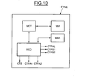
- the power amplification stage of the TP mobile phone here includes a MAGV variable gain amplification means including the input is connected to the output of the CHM transmission channel.
- the exit of the MAGV amplification means is connected to the AMT antenna by through a DUP duplexer.
- the MAGV amplification means is supplied by a ALM power supply, preferably a switching power supply, which delivers, in response to a CTPAL control signal issued by the means ETNE the supply voltage Valim of the medium MAGV amplification, from the phone battery voltage VBAT.
- the ETNE processing means deliver a CTPG gain control signal used to adjust the value of the gain in amplification means.
- the ETNE stage delivers the CTPG signal to adjust the gain value as a function of the new transmission power required.
- the stage ETNE comprises a memory MM1 storing a table providing for each value of the required transmission power and of the gain, a value of the supply voltage Valim. Consequently, the stage ETNE delivers the control signal CTPAL to the switching power supply ALM so that the latter delivers this voltage Valim taking into account the voltage of the battery and this in order to minimize the back- off the amplification means.
- the power amplification stage of the TP mobile phone here comprises two power amplifiers PA1 and PA2, of classical structure and known per se, the respective entrances of which are connected to the outputs of MSW selection means formed here by a duplexer controlled by a CTS selection signal developed and delivered by the ETNE processing stage.
- the input of the MSW duplexer is connected at the exit of the CHM broadcast channel.
- the respective outputs of two amplifiers P1 and PA2 are connected to the ANT antenna by through the DUP duplexer.
- each amplifier PA1, PA2 is controlled by a control signal CTPA1, CTPA2 to inhibit sound operation.
- CTPA1 and CTPA2 are also delivered by the ETNE processing stage.
- each amplifier of power has a specific operating area and an area operating in common with the other power amplifier.
- the amplifier PA1 has an area specific operating ZFO1, for which the efficiency (efficiency) of the amplifier increases from a value EF1 to a EFM1 value, for example in a power zone between VP0 dBm and Pmax .. For powers lower than VP0 dBm the efficiency of the amplifier PA1 decreases from the value EF1
- the specific operating zone ZFO2 of the PA2 amplifier ranges from Pmin to VP11 dBm.
- the effectiveness of amplifier PA2 then continues to increase to reach the value EFM2 to VP0 dBm.
- the two power amplifiers therefore cover together the entire power range, from Pmin to Pmax. They have different fixed earnings.
- Each point in the power range is associated with one of the amplifiers according to an attribution criterion which here takes into counts efficiency in combination with the need to switch amplifier under conditions suitable for transmission Datas.
- all the operating points between Pmin and VP11 dBm are associated with the PA2 amplifier.
- all the operating points between VP0 dBm and Pmax are associated with amplifier PA1.
- the PA2 amplifier has the best efficiency. However, if the required power continues to increase, it then switch to PA1 amplifier. This is the reason for which, we define in this common area a point of operation beyond which the decision to switch. This point is for example the point P6 corresponding to the power value VP6.
- This correspondence table between an operating point and a power amplifier is stored in a memory MM of the ETNE stage (figure 5).
- the floor ETNE also includes MCT control means and MCD control means. These means are for example made of software way within a microprocessor.
- TPC power information ( Figure 6) is received at within each time interval SLi, and the power variation between two successive power information is for example 1 dBm.
- the TPC power information received by the stage of ETNE treatment is located in the specific operating zone of PA1 amplifier (which we assume selected here) and outside ZFC common operating area, there is no need to change power amplifier and transmit power can continue to be adjusted with the TPC information using PA1 amplifier selected.
- the control means range from in general, check whether this TPCi power information received (step 90, figure 10) corresponds to the amplifier currently selected (step 91), that is to say the amplifier PA1. If this is the case, there is no change in the amplifier selection power. This is the case for example for the operating points PF0 to PF5.
- step 90 if a TPCi power information received in step 90 (FIG. 10) corresponds to the operating point PF6, it then switch the power amplifier and select the PA2 amplifier.
- the MCT control means will then define a PCM switching time range (step 92) extending from the instant of receipt of said power information TPCi (corresponding to operating point PF6), over a period predetermined compatible with the limits of said common area CFZ.
- the MCT control means will also define in as a function of a predetermined CRF emission interruption criterion, of which we will come back in more detail below on the content, the limits of a PIT interrupt time range in said PCM switching range.
- the means of control will define, from from point PF5, a switching range within which it will be possible to change power amplifier while continuing, before this switching point, adjust the transmit power by using the currently selected amplifier, i.e. PA1 amplifier, although this has lower efficiency than that of the PA2 amplifier.
- the limit of the switching range for example here will be that defined by point PF10. Indeed, between points PF6 and PF10, the efficiency of the PA1 amplifier remains acceptable, whereas beyond point PF10 it is considered too low.
- the duration of the switching range here corresponds to four intervals.
- the control means will check whether this power information TPCi received (step 90, FIG. 10) corresponds to the amplifier currently selected (step 91), i.e. PA2 amplifier. If this is the case, there is no modification of power amplifier selection. It's the case for example for operating points P11 to P6.
- step 90 if a TPCi power information received in step 90 (FIG. 10) corresponds to the operating point P5, it then switch the power amplifier and select the PA1 amplifier.
- the MCT control means will define the range PCM switching time (step 92) extending from the instant of receiving said power information TPCi (corresponding at operating point P5), over a predetermined period compatible with the limits of the said ZFC common area.
- the MCT control means will also define in according to the predetermined CRF transmission interruption criterion, the time limits of the PIT interrupt time range lying in said PCM switching range.
- the means of control will define, from from point P5, a switching range within which it will be possible to change power amplifier while continuing, before this switching point, adjust the transmit power by using the currently selected amplifier, i.e. PA2 amplifier.
- the limit of the switching range will be example here that defined by point P1.
- control means will define according to the interruption criterion the PIT interrupt time range that goes correspond to the best times to change amplifier, this change requiring prior cessation of the transmission of phone.
- the control means will detect in step 93 the occurrence of the PIT interrupt range. As long as this range is not reached, the control means will authorize the continuation (step 95) of the adjustment of the transmission power with the currently selected amplifier, i.e. here the amplifier PA1, possibly based on new information from TPC power received. So, if for example, the time range PIT interrupt must occur at a time corresponding to a operating point located between points PF7 and PF8, the power will continue to be adjusted until the occurrence of this PIT interrupt range using TPC information corresponding to points PF6 and PF7 (steps 96 and 97).
- control means each time a new power information TPCi + 1, the control means check whether the new power information received corresponds to the currently selected amplifier, i.e. the amplifier PA1 (step 97). If this were the case (for example if the information of power received immediately after that associated with point PF6 corresponds to operating point PF5), there is no longer any need to change power amplifier and power amplifier currently selected PA1 is kept selected (step 98).
- control means When the control means detect the occurrence of the time range of interruption, they then initiate the process of switching (step 94) illustrated in Figure 11.
- control means will inhibit the emission (I, Q) during the whole duration of the PIT interrupt range. Then, they will deliver to the means MSW selection, the CTS selection information corresponding to the power amplifier associated with the last information of received power, then they will reactivate the transmission with the new amplifier selected.
- the CTPA2 control signal is set to 1, thus activating the operation of the PA2 amplifier.
- the control means reactivate show I, Q.
- This time schedule may be repeated later during another interrupt time range PIT2 in case it would be necessary to start over on the amplifier PA1.
- the duration of the PIT interrupt time range is also chosen so as to minimize the risk of transmission while allowing efficient and clean switching amplifiers. For example, we can choose a duration of the order of a few chips, for example two to four fragments, which corresponds to a duration of up to one microsecond approx.
- the CRF emission interruption criterion includes the choice of at least one specific predetermined event that may occur during a broadcast and have an impact predetermined on the bit error rate in case of interruption of emission during the occurrence of this particular event.
- the criterion of interruption of transmission advantageously comprises the choice of a group of several predetermined particular events which may be occur during a broadcast, and the scheduling of these particular events according to a predetermined order of priority in according to their respective impacts on the bit error rate in case of interruption of emission during the occurrence of these events individuals.
- the particular event having the highest priority high will lead to the lowest bit error rate if of interruption of emission during the occurrence of this event highest priority.
- the particular event having the lower priority will lead to a higher bit error rate.
- the control means will then analyze the characteristics of the transmission by considering said order of priority, so as to detect the possible presence during said PCM switching range of a particular predetermined event of said group. And, the means of control will then place said PIT interrupt time range during the occurrence of the first particular event thus detected in order of priority.
- FIG. 6 schematically illustrates a TRE transmission frame within which information from the telephone is sent to the base station (uplink: "Uplink") in a normal operating mode. More specifically, in a way analogous to the reception frame TRR (FIG. 5), the transmission frame TRE is also subdivided into fifteen SLi intervals. Within each Sli interval are conveyed in parallel the data channel DPDCH and the DPCCH control channel. More specifically, the control indications carried include a word PLT relating to a pilot signal, a TFCI word corresponding to an indicator of transport format combination, an FBI word corresponding to a feedback and a TPC word corresponding to a piece of information of emitted power. Those skilled in the art may also refer to the aforementioned 3G TS 25.211 specification for more details concerning the structure of a TRE transmission frame.
- the data contained in the data channel DPDCH can be spread with a spreading factor ("spreading factor ”) variable.
- This spreading factor can vary from 4 to 256 according to the quality of service required.
- the information transmitted can be in a so-called “compressed” transmission mode ("compressed mode" in English).
- compressed mode in English
- empty intervals TGP separating transmission intervals SLj and SLk and during which no information is sent.
- the skilled person may refer to the technical specification 3G TS 25.212 from from the same organization (3 GPP) as previously mentioned.
- the mobile phone can also, in certain circumstances, communicate with the base in a so-called "gated mode" English).
- this chopped transmission mode the transmission must be interrupted during certain intervals of each frame.
- the number of intervals during which the program must be interrupted, as well as their position in the frame, depend on the rate of hash.
- Such a chopped transmission mode is also known from the skilled person. For more details, it may nevertheless be refer to the specification 3G TR 25.840, from the Organization previously mentioned (3GPP).
- Mobile phone can also talk to the station basic in a discontinuous transmission mode ("DTX mode" in English language).
- DTX mode discontinuous transmission mode
- Such a mode of transmission is also good known to those skilled in the art. It is characterized in particular, as illustrated in Figure 8, by intervals of INS silence during of which no data is sent on the DPDCH data channel in base station management.
- the DPCCH control channel continues to be transmitted and may include the words FBI and TFCI.
- the means of control go first detect if the PCM switching range will contain at least one TGP empty interval in compressed transmission mode. If so, the control means will set the transmission interrupt range PIT in this empty interval.
- control means will detect the possible presence of a chopped transmission mode and will then place the PIT transmission interrupt range in one of the intervals at during which the broadcast can be interrupted.
- control means will detect the possible presence of a discontinuous mode of transmission and then go set the PIT transmission interrupt range during a game P1INS or P2INS ( Figure 8).
- the means of control will then detect the possible presence of parts of intervals during from which we send the data with a high spreading factor, but during which no FBI feedback is sent, nor TFCI transport format combination indicators. If this detection is positive, the control means will place the range transmission interruption during these parts of intervals.
- control means will try to detect parts of intervals during which emits data with a low spreading factor, but during from which there is still no FBI feedback, or TFCI transport format combination indicators. Ways control will then set the PIT transmission interrupt range during these parts of intervals.
- control means will then set the interruption range of PIT transmission in parts of the intervals during which we send back FBI information or indicators of TFCI transport format combination.
- control means MCD of the stage ETNE will, from the content of the memory MM1 deliver to the power supply switching ALM the CTPAL signal so as to adjust the voltage power supply of the selected amplifier.
- the two amplifiers PA1 and PA2 are this time with variable gain.
- the principle of selection and switching of these two amplifiers is identical to that just described with reference to the figures preceding.
- the means of MCD command also deliver to the selected amplifier, the gain control signal CTPG1 (for amplifier PA1) or CTPG2 (for PA2 amplifier).
- the MCLD control means deliver always with switching power supply, the control signal corresponding so as to adjust the supply voltage of the amplifier selected to minimize the back-off of this amplifier.
- the invention is not limited to the embodiments and implementation which have just been described but embraces all the variants. Thus, it is particularly advantageous to control also the accuracy of the output power.
- FIG. 1 on which the means additional of this embodiment have been shown in dashed, we see that there is an MCPS control block, receiving on the one hand the level of the output power delivered by the MAGV amplifier and on the other hand the CTPG control signal from the power setpoint received by the terminal, and delivering after comparing the two inputs, the gain control signal the MAGV amplifier.
- control block The presence of such a control block is also conceivable in the embodiments illustrated in Figures 2 and 12.
- the control signal gain would then be delivered for example to a gain preamplifier variable.
Abstract
Description
L'invention concerne d'une façon générale les systèmes de communication sans fil, notamment ceux destinés à fonctionner selon la norme UMTS.The invention relates generally to wireless communication, especially those intended to operate according to the UMTS standard.
Dans un système de communication sans fil, une station de base communique avec une pluralité de terminaux distants, tels que des téléphones mobiles cellulaires. Les accès multiples par division de fréquence (FDMA : "Fréquency-Division Multiple Access" en langue anglaise) et les accès multiples par division temporelle (TDMA : "Time Division Multiple Access" en langue anglaise) sont les schémas d'accès multiples traditionnels pour délivrer des services simultanés à un certain nombre de terminaux. L'idée de base sous-jacente aux systèmes FDMA et TDMA consiste à partager la ressource disponible, respectivement en plusieurs fréquences ou en plusieurs intervalles temporels, de telle sorte que plusieurs terminaux peuvent fonctionner simultanément sans provoquer d'interférence.In a wireless communication system, a base station communicates with a plurality of remote terminals, such as cellular mobile phones. Multiple accesses by division of frequency (FDMA: "Fréquency-Division Multiple Access" in language English) and multiple accesses by time division (TDMA: "Time Division Multiple Access" in English) are the diagrams traditional multiple access to deliver simultaneous services to a number of terminals. The basic idea behind FDMA and TDMA systems consists in sharing the available resource, respectively in several frequencies or in several intervals temporal, so that multiple terminals can operate simultaneously without causing interference.
Les téléphones fonctionnant selon la norme GSM appartiennent aux systèmes FDMA et TDMA en ce sens que l'émission et la réception s'effectuent à des fréquences différentes et également à des intervalles temporels différents.GSM standard phones belong to to FDMA and TDMA systems in that the transmission and reception takes place at different frequencies and also at different time intervals.
A l'opposé de ces systèmes utilisant une division de fréquence ou une division temporelle, les systèmes CDMA (Système à accès multiples par division de code; "Code Division Multiple Access" en langue anglaise) permettent aux utilisateurs multiples de partager une fréquence commune et un canal temporel commun en utilisant une modulation codée. Parmi les systèmes CDMA on peut citer le système CDMA 2000, le système WCDMA ("Wide Band CDMA" en langue anglaise; CDMA large bande) ou la norme IS-95.In contrast to these systems using frequency division or a time division, CDMA systems (Access system multiples by code division; "Code Division Multiple Access" in English language) allow multiple users to share a common frequency and a common time channel using a coded modulation. Among the CDMA systems one can cite the system CDMA 2000, the WCDMA system ("Wide Band CDMA" in language English; CDMA broadband) or IS-95.
Dans les systèmes CDMA, comme il est bien connu par l'homme du métier, un code d'embrouillage ("scrambling code" en langue anglaise) est associé à chaque station de base et permet de distinguer une station de base d'une autre. En outre, un code orthogonal, connu par l'homme du métier sous la dénomination de "Code OVSF", est alloué à chaque terminal distant (comme par exemple un téléphone mobile cellulaire). Tous les codes OVSF sont orthogonaux entre eux, ce qui permet de distinguer un terminal distant d'un autre.In CDMA systems, as is well known by a person skilled in the art, a scrambling code in English language) is associated with each base station and allows distinguish one base station from another. In addition, a code orthogonal, known to a person skilled in the art under the name of "OVSF code" is allocated to each remote terminal (as per cell phone). All OVSF codes are orthogonal to each other, which makes it possible to distinguish a remote terminal of another.
Avant d'émettre un signal sur le canal de transmission à destination d'un terminal distant, le signal a été embrouillé et étalé ("spreaded " en langue anglaise) par la station de base en utilisant le code d'embrouillage de la station de base et le code OVSF du terminal distant.Before transmitting a signal on the transmission channel to destination of a remote terminal, the signal has been scrambled and spread ("spreaded" in English) by the base station using the base station scrambling code and terminal OVSF code remote.
Dans les systèmes CDMA, on peut encore distinguer ceux qui utilisent une fréquence distincte pour l'émission et la réception (système CDMA-FDD) et ceux qui utilisent une fréquence commune pour l'émission et la réception, mais des domaines temporels distincts pour l'émission et la réception (système CDMA-TDD).In CDMA systems, one can still distinguish those which use a separate frequency for transmission and reception (CDMA-FDD system) and those using a common frequency for transmission and reception, but separate time domains for transmission and reception (CDMA-TDD system).
L'invention s'applique avantageusement aux systèmes de communication du type CDMA, et plus particulièrement aux systèmes du type CDMA-FDD.The invention advantageously applies to CDMA type communication, and more particularly to systems of the CDMA-FDD type.
Ceci étant, l'invention s'applique également aux systèmes de communication du type FDMA et TDMA, en particulier aux téléphones GSM et GPRS, et plus généralement aux terminaux fonctionnant selon la norme UMTS qui doivent être capables par exemple de fonctionner à la fois sous un système CDMA, comme le système WCDMA et sous un système FDMA et TDMA.However, the invention also applies to FDMA and TDMA communication, in particular on telephones GSM and GPRS, and more generally at terminals operating according to the UMTS standard which must be able for example to operate at both under a CDMA system, like the WCDMA system and under a FDMA and TDMA system.
Dans les terminaux distants, tels que les téléphones mobiles cellulaires, il est actuellement prévu un seul amplificateur de puissance pour l'émission, cet amplificateur de puissance ayant une large plage de fonctionnement de puissance radiofréquence. Et, notamment dans les systèmes CDMA-FDD, l'amplificateur de puissance est continuellement en fonctionnement pendant les communications. In remote terminals, such as mobile phones cellular, there is currently only one amplifier power for transmission, this power amplifier having a wide operating range of radio frequency power. And, especially in CDMA-FDD systems, the power is continuously running during communications.
Par ailleurs, la puissance d'émission délivrée par l'amplificateur de puissance, peut varier dans une plage de puissances prédéterminée, typiquement de -50 dBm à 24 dBm pour les téléphones mobiles de troisième génération. Dans cette plage de puissance, la puissance d'émission est ajustée en fonction d'informations de puissance régulièrement reçues par le téléphone et en provenance de la station de base.Furthermore, the transmission power delivered by the power amplifier, can vary within a power range predetermined, typically from -50 dBm to 24 dBm for telephones third generation mobiles. In this power range, the transmit power is adjusted based on information from power regularly received by the phone and coming from the base station.
Actuellement, l'amplificateur de puissance est conçu de façon à présenter l'efficacité la plus grande pour la puissance d'émission maximale. Par contre, pour les puissances intermédiaires ou basses, il se produit une détérioration significative de l'efficacité puisque le courant de repos de l'amplificateur de puissance ne change pas, tandis que la puissance émise décroít. Ainsi, dans ces modes de fonctionnement à puissance faible ou intermédiaire, l'efficacité, c'est-à-dire le rendement, décroít de façon drastique jusqu'à des valeurs inférieures au pourcent.Currently, the power amplifier is designed to present the greatest efficiency for the transmission power Max. On the other hand, for intermediate or low powers, it a significant deterioration in efficiency occurs since the quiescent current of the power amplifier does not change, while that the transmitted power decreases. So in these modes of operating at low or intermediate power, efficiency, i.e. the yield decreases drastically to values less than a percent.
Il en résulte alors une perte d'énergie au niveau de la batterie, ce qui diminue sa durée de vie.This then results in a loss of energy in the battery, which shortens its lifespan.
L'invention vise à apporter une solution à ce problème.The invention aims to provide a solution to this problem.
Un but de l'invention est de contrôler la puissance d'émission d'un terminal distant en particulier un téléphone mobile cellulaire, de façon à optimiser son efficacité sans affecter la qualité du service transmis et sans provoquer notamment de distorsion du signal.An object of the invention is to control the transmission power a remote terminal, in particular a cellular mobile telephone, so as to optimize its efficiency without affecting the quality of service transmitted and without causing in particular distortion of the signal.
L'invention propose donc un procédé de contrôle de la puissance d'émission d'un terminal distant d'un système de communication sans fil, par exemple un téléphone mobile cellulaire, dans une plage de puissance prédéterminée, procédé dans lequel on ajuste la puissance d'émission en fonction d'informations de puissance (consignes) reçues par le téléphone.The invention therefore provides a method for controlling the transmission power of a remote terminal of a wireless communication, for example a cellular mobile telephone, within a predetermined power range, method in which adjusts transmit power based on power information (instructions) received by phone.
Selon une caractéristique générale de l'invention, on équipe le téléphone avec un moyen d'amplification à gain variable capable de couvrir ladite plage de puissance, et on règle la valeur du gain et de la tension d'alimentation du moyen d'amplification en fonction desdites informations de puissance. According to a general characteristic of the invention, the telephone with variable gain amplification capable of cover said power range, and the value of gain and supply voltage of the amplification means as a function of said power information.
L'invention permet donc d'ajuster d'une part le gain du moyen d'amplification en fonction de la puissance demandée de façon à limiter au maximum toute dissipation thermique de puissance. Par ailleurs, l'homme du métier sait que l'un des paramètres d'un amplificateur est le recul par rapport à son point de saturation (plus connu par l'homme du métier sous sa dénomination anglaise de « back-off »). Or, une modification du gain de l'amplificateur et par conséquent une modification de sa puissance de sortie entraíne une modification du back-off qui peut dans certains cas devenir trop faible augmentant alors les risques d'un fonctionnement non linéaire de l'amplificateur (distorsion du signal). Or, l'invention en réglant également la valeur de la tension d'alimentation du moyen d'amplification vise à obtenir un back-off optimum.The invention therefore makes it possible to adjust on the one hand the gain of the means amplification as a function of the power requested so as to minimize any heat dissipation of power. Through elsewhere, those skilled in the art know that one of the parameters of a amplifier is the setback from its saturation point (more known to the skilled person by his English name of "back-off "). However, a modification of the gain of the amplifier and by therefore a change in its output power results in a modification of the back-off which can in some cases become too weak increasing the risk of non-linear operation by the amplifier (signal distortion). Now, the invention by regulating also the value of the medium supply voltage of amplification aims to obtain an optimum back-off.
Bien que l'utilisation comme moyen d'amplification, d'un seul amplificateur de puissance à gain variable capable de couvrir toute la gamme de puissance soit envisageable, on peut également réaliser le moyen d'amplification à gain variable à partir d'au moins deux amplificateurs de puissance individuellement sélectionnables, capables de couvrir ensemble la totalité de la plage de puissance, et possédant respectivement deux zones de fonctionnement spécifiques différentes et une zone commune de fonctionnement. Et, la sélection de l'un ou de l'autre de ces deux amplificateurs conduit fonctionnellement à une variation du gain de l'étage amplificateur.Although use as a means of amplification, only one variable gain power amplifier capable of covering the entire power range is possible, we can also realize the variable gain amplification means from at least two individually selectable power amplifiers capable to cover the entire power range together, and having respectively two different specific operating zones and a common operating area. And, the selection of one or the other of these two amplifiers functionally leads to a variation of the gain of the amplifier stage.
On associe alors avantageusement l'un des amplificateurs à chaque point de la plage de puissance en fonction d'un critère d'attribution prédéterminé. Ce critère d'attribution est de préférence un critère d'efficacité. Ainsi, on peut par exemple associer à chaque point de la plage de puissance l'amplificateur dont le rendement est le plus élevé pour ce point. Ceci peut aisément s'appliquer par exemple pour un système GSM dans lequel les moyens de traitement du téléphone connaissent la puissance requise par la station de base à l'instant de l'occurrence temporelle de l'intervalle temporel alloué au téléphone. Aussi, en fonction de cette information de puissance, l'un ou l'autre des amplificateurs pourra être sélectionné juste avant le début de l'intervalle temporel alloué au téléphone Ceci étant, comme on le verra plus en détail ci-après, un tel critère d'efficacité peut être modulé, par exemple dans les systèmes WCDMA pour prévoir une commutation des amplificateurs avec une perturbation moindre pour la transmission des données. Ceci peut alors conduire à associer certains points de la zone commune à l'amplificateur qui présente la plus grande efficacité et à associer certains autres points de la zone commune à l'amplificateur qui ne présente pas la plus grande efficacité.One of the amplifiers is then advantageously associated with each point of the power range according to a criterion of predetermined allocation. This award criterion is preferably an efficiency criterion. So we can for example associate with each point of the power range the amplifier whose efficiency is the higher for this point. This can easily be applied for example for a GSM system in which the means for processing the phone know the power required by the base station to the instant of the temporal occurrence of the temporal interval allocated to the phone. Also, based on this power information, one either of the amplifiers can be selected just before start of the time interval allocated to the telephone However, as as will be seen in more detail below, such an effectiveness criterion may be modulated, for example in WCDMA systems to provide a switching amplifiers with less disturbance for the data transmission. This can then lead to associating certain points in the area common to the amplifier with the most high efficiency and to combine certain other points in the area common to the amplifier which does not have the greatest efficiency.
Dans un mode particulier de mise en oeuvre s'appliquant tout particulièrement à un système GSM, en présence d'une information de puissance reçue correspondant à un point de la zone commune, on vérifie si cette information de puissance correspond à l'amplificateur actuellement sélectionné. Si tel est le cas, on continue à utiliser l'amplificateur pour la délivrance de la puissance d'émission. Dans le cas contraire, on sélectionne l'amplificateur de puissance associée à ladite information de puissance. Dans tous les cas, quel que soit l'amplificateur sélectionné, on règle en outre la valeur de la tension d'alimentation de cet amplificateur en fonction des informations de puissance.In a particular mode of implementation applying all particularly to a GSM system, in the presence of information of received power corresponding to a point in the common area, we check if this power information matches the amplifier currently selected. If this is the case, we continue to use the amplifier for the delivery of the transmission power. In the otherwise, we select the power amplifier associated with said power information. In any case, whatever the selected amplifier, the value of the voltage is also adjusted power supply of this amplifier according to the information of power.
Le fait de prévoir une zone commune de fonctionnement pour les deux amplificateurs permet de prendre en compte les imprécisions éventuelles sur les valeurs des gains des deux amplificateurs, de façon à éviter notamment tout « trou» dans la plage de puissance.Providing a common operating area for the two amplifiers take into account the inaccuracies possible on the gain values of the two amplifiers, so especially to avoid any "hole" in the power range.
En variante, l'un au moins des amplificateurs peut être à gain variable. Et, outre la sélection de l'un de ces amplificateurs, on règle avantageusement la valeur du gain d'amplificateur sélectionné en fonction de l'information de puissance.As a variant, at least one of the amplifiers can be gain variable. And, in addition to the selection of one of these amplifiers, advantageously the value of the amplifier gain selected in power information function.
Dans un système CDMA, et notamment un système WCDMA, l'amplificateur de puissance est continuellement en fonctionnement pendant les communications puisqu'il n'y a pas de notion de partage temporel. Aussi, il convient dans ce cas, lorsqu'on utilise également deux amplificateurs de puissance individuellement sélectionnables et capables de couvrir ensemble la totalité de la plage de puissance, de choisir l'instant de commutation qui va occasionner une perturbation minimale dans la transmission.In a CDMA system, and in particular a WCDMA system, the power amplifier is continuously in operation during communications since there is no notion of sharing temporal. Also, it is suitable in this case, when also using two individually selectable power amplifiers and capable of covering the entire power range, from choose the switching time which will cause a disturbance minimum in transmission.
C'est pourquoi, en présence d'une information de puissance reçue correspondant à un point de la zone commune, on vérifie si cette information de puissance correspond à l'amplificateur actuellement sélectionné. Si tel est le cas, on continue à utiliser cet amplificateur pour la délivrance de la puissance d'émission.This is why, in the presence of power information received corresponding to a point in the common area, we check whether this power information corresponds to the amplifier currently selected. If this is the case, we continue to use this amplifier for the delivery of transmission power.
Dans le cas contraire, on définit une plage temporelle de commutation s'étendant depuis l'instant de réception de ladite information de puissance sur une durée prédéterminée compatible avec les limites de ladite zone commune. On définit également en fonction d'un critère prédéterminé d'interruption d'émission, les limites temporelles d'une plage temporelle d'interruption se situant dans ladite plage de commutation.Otherwise, we define a time range of switching extending from the instant of receipt of said power information over a predetermined period compatible with the limits of the said common area. We also define according of a predetermined emission interruption criterion, the limits times of a time range of interruption lying in said switching range.
On continue, éventuellement à partir de nouvelles informations de puissance reçues, à ajuster la puissance d'émission avec l'amplificateur actuellement sélectionné jusqu'à l'occurrence de ladite plage d'interruption. Puis, si la dernière information de puissance reçue avant l'occurrence de ladite plage d'interruption, ne correspond toujours pas à l'amplificateur actuellement sélectionné, on inhibe l'émission pendant ladite plage d'interruption, on sélectionne l'amplificateur de puissance associé à ladite dernière information de puissance, et on réactive l'émission avec le nouvel amplificateur sélectionné.We continue, possibly from new information received power, adjust the transmit power with the amplifier currently selected until the occurrence of said interrupt range. Then, if the last power information received before the occurrence of said interrupt range, does not correspond still not at the currently selected amplifier, we inhibit transmission during said interruption range, we select the power amplifier associated with said last information of power, and we reactivate the emission with the new amplifier selected.
En d'autres termes, lorsque la puissance d'émission requise par la station de base atteint une limite pour l'amplificateur de puissance actuellement sélectionné, cet amplificateur de puissance doit être commuté. Mais, puisque cet amplificateur de puissance (qui doit être désélectionné) et le nouvel amplificateur de puissance (qui doit être sélectionné) possèdent une zone de fonctionnement commune, le point de commutation peut être choisi de façon flexible dans une plage temporelle (plage de commutation) correspondant aux limites de la zone de fonctionnement commune. Et, à l'intérieur de cette plage de commutation, l'invention prévoit de choisir l'instant de commutation qui va occasionner une perturbation minimale dans la transmission.In other words, when the transmission power required by the base station reaches a limit for the power amplifier currently selected, this power amplifier must be switched. But, since this power amplifier (which must be deselected) and the new power amplifier (which must be selected) have a common operating area, the point switching can be flexibly chosen within a range time (switching range) corresponding to the limits of the common operating area. And, within this range of switching, the invention provides for choosing the switching instant which will cause minimal disruption in transmission.
Là encore, tout comme pour les systèmes GSM, on peut, dans les systèmes CDMA prévoir que l'un au moins des amplificateurs soit à gain variable. Et, outre le fait de régler la tension d'alimentation en fonction des informations de puissance, on réglera en outre la valeur du gain de l'amplificateur sélectionné en fonction de l'information de puissance.Again, just like with GSM systems, you can, in CDMA systems provide that at least one of the amplifiers is variable gain. And, in addition to adjusting the supply voltage in depending on the power information, the value will also be set the gain of the selected amplifier according to the information of power.
Généralement, les informations émises sont formées de "fragments" ("chips" en langue anglaise) et sont véhiculées au sein de trames successives subdivisées chacune en un nombre prédéterminé d'intervalles ("slots" en langue anglaise). La durée de la plage de commutation est alors avantageusement de l'ordre de quelques intervalles, par exemple quatre à huit intervalles. De même, la durée de la plage temporelle d'interruption est avantageusement de l'ordre de quelques fragments, par exemple deux à quatre fragments.Generally, the information sent consists of "fragments" ("chips" in English) and are conveyed within successive frames each subdivided into a predetermined number intervals ("slots" in English). The duration of the range of switching is then advantageously of the order of a few intervals, for example four to eight intervals. Likewise, the duration the interruption time range is advantageously of the order of some fragments, for example two to four fragments.
Selon un mode particulier de mise en oeuvre de l'invention, le critère d'interruption d'émission comporte le choix d'au moins un évènement particulier prédéterminé pouvant se produire au cours d'une émission et ayant un impact prédéterminé sur le taux d'erreur binaire (BER : "Binary Error Rate" en langue anglaise) en cas d'interruption d'émission lors de l'occurrence de cet évènement particulier. On analyse alors les caractéristiques de l'émission de façon à détecter la présence éventuelle de cet évènement particulier prédéterminé à l'intérieur de la plage de commutation. Et, si cette présence est effective, on place ladite plage temporelle d'interruption lors de l'occurrence de cet évènement particulier.According to a particular embodiment of the invention, the emission interruption criterion includes the choice of at least one specific predetermined event that may occur during a emission and having a predetermined impact on the bit error rate (BER: "Binary Error Rate" in English) in case of interruption of emission during the occurrence of this particular event. We then analyzes the characteristics of the program in order to detect the possible presence of this particular predetermined event at within the switching range. And, if this presence is effective, we place said time interruption range during the occurrence of this particular event.
Ainsi, l'interruption de l'émission pour permettre la commutation des amplificateurs aura l'impact prédéterminé souhaité sur l'émission, en pratique un impact négligeable.Thus, the interruption of the broadcast to allow the switching amplifiers will have the desired predetermined impact on the broadcast, in practice a negligible impact.
Il est particulièrement avantageux que le critère d'interruption d'émission comporte le choix d'un groupe de plusieurs évènements particuliers prédéterminés pouvant se produire au cours d'une émission, et l'ordonnancement de ces évènements particuliers selon un ordre de priorité prédéterminé en fonction de leurs impacts respectifs sur le taux d'erreur binaire en cas d'interruption d'émission lors de l'occurrence de ces évènements particuliers.It is particularly advantageous that the interruption criterion program includes the choice of a group of several events predetermined individuals that may occur during a emission, and the scheduling of these particular events according to a predetermined priority order according to their respective impacts on the bit error rate in the event of transmission interruption during the occurrence of these particular events.
Ainsi, par exemple, l'événement particulier ayant la priorité la plus élevée correspondra à celui pour lequel l'impact sur le taux d'erreur binaire sera le plus faible si l'interruption de l'émission se produit lors de l'occurrence de cet évènement particulier.So, for example, the particular event with priority higher will correspond to the one for which the impact on the rate bit error rate will be the lowest if the interruption of the transmission produced during the occurrence of this particular event.
L'évènement particulier qui sera alors affecté de la priorité la plus faible correspondra à celui dont l'impact sur le taux d'erreur binaire sera le plus élevé, si l'interruption de l'émission se produit au cours de cet évènement particulier.The particular event which will then be assigned priority lower will correspond to the one whose impact on the error rate binary will be the highest, if the interruption of the emission occurs at the during this particular event.
On analyse alors avantageusement les caractéristiques de l'émission en considérant ledit ordre de priorité, de façon à détecter la présence éventuelle pendant ladite plage de commutation d'un évènement particulier prédéterminé dudit groupe. Et, on place ladite plage temporelle d'interruption lors de l'occurrence du premier évènement particulier ainsi détecté dans l'ordre de priorité.The characteristics of the transmission by considering said order of priority, so as to detect the possible presence during said switching range of a particular predetermined event of said group. And, we place said time range of interruption on the occurrence of the first particular event thus detected in order of priority.
En d'autres termes, si on détecte la présence de l'événement particulier ayant la priorité la plus élevée, c'est au cours de l'occurrence de cet évènement que l'on placera ladite plage d'interruption. Par contre, si l'on ne détecte pas un évènement particulier affecté de la priorité la plus élevée, on cherchera alors à détecter un évènement ayant une priorité plus faible, et ainsi de suite. Et, dès que l'on détecte un évènement particulier, on place la plage d'interruption lors de l'occurrence de cet évènement particulier.In other words, if we detect the presence of the event individual with the highest priority, it is during the occurrence of this event that we will place said range interruption. On the other hand, if we do not detect an event particular individual with the highest priority, we will then seek to detect an event with a lower priority, and so on. And, as soon as we detect a particular event, we place the range of interruption during the occurrence of this particular event.
Ainsi, lorsque les informations émises comportent des données et des indications de contrôle, et sont véhiculées au sein de trames successives subdivisées chacune en un nombre prédéterminé d'intervalles, les indications de contrôle comportant des informations en retour (FBI : "Feedback Information") et des indicateurs de combinaison de format de transport (TFCI : "Transport Format Combination Indicator"), le groupe d'évènements particuliers est alors constitué, par exemple, par ordre de priorité décroissant :
- des intervalles vides lors d'un mode d'émission comprimé (cet évènement particulier étant alors affecté de la priorité la plus élevée),
- des intervalles au cours desquels l'émission doit être interrompue dans un mode d'émission dit "hâché" ("gated mode" en langue anglaise),
- des parties des intervalles de silence dans un mode de transmission discontinu, au cours desquelles on n'émet ni informations en retour (FBI), ni indicateurs de combinaison de format de transport (TFCI),
- des parties des intervalles au cours desquelles on émet des données ayant un facteur d'étalement ("spreading factor" en langue anglaise) élevé, par exemple 128 ou 256, mais au cours desquelles on n'émet ni informations en retour (FBI), ni indicateurs de combinaison de format de transport (TFCI),
- des parties des intervalles au cours desquelles on émet des données ayant un facteur d'étalement faible, c'est-à-dire inférieur ou égal à 64, mais sans émettre ni informations en retour (FBI), ni indicateurs de combinaison de format de transport (TFCI),
- des parties des intervalles au cours desquelles on émet des informations en retour (FBI) ou des indicateurs de combinaison de format de transport (TFCI).
- empty intervals during a compressed transmission mode (this particular event then being assigned the highest priority),
- intervals during which the transmission must be interrupted in a transmission mode known as "hacked"("gatedmode" in English),
- parts of the intervals of silence in a discontinuous transmission mode, during which neither information in return (FBI) nor transport format combination indicators (TFCI) are transmitted,
- parts of the intervals during which data with a high spreading factor (for example 128 or 256) are sent, but during which no information is returned (FBI), neither transport format combination indicators (TFCI),
- parts of the intervals during which data with a low spreading factor, that is to say less than or equal to 64, are transmitted, but without sending any feedback information (FBI) or combination format indicators transport (TFCI),
- parts of the intervals during which information is returned (FBI) or transport format combination indicators (TFCI).
Ce dernier évènement est celui qui a la priorité la plus faible et qui a par conséquent l'impact le plus élevé sur le taux d'erreur binaire. Mais, à défaut d'avoir trouvé un évènement particulier ayant une priorité plus élevée dans la liste qui vient d'être évoquée, on choisira néanmoins de commuter l'amplificateur au cours de la transmission des informations de contrôle FBI ou TFCI, plutôt que de risquer de perdre la transmission.This last event is the one with the lowest priority and which therefore has the highest impact on the bit error rate. But, failing to have found a particular event having a higher priority in the list which has just been mentioned, we will choose nevertheless to switch the amplifier during the transmission of FBI or TFCI control information, rather than risking losing the transmission.
L'invention a également pour objet un terminal distant pour système de communication sans fil, par exemple un téléphone mobile cellulaire, comprenant une chaíne de réception, une chaíne d'émission, un étage d'amplification de puissance connecté entre la chaíne d'émission et l'antenne, et un étage de traitement apte à ajuster la puissance de sortie de l'étage d'amplification en fonction d'informations de puissance régulièrement reçues par la chaíne de réception.The invention also relates to a remote terminal for wireless communication system, such as a mobile phone cellular, comprising a reception chain, a transmission chain, a power amplification stage connected between the chain and the antenna, and a processing stage capable of adjusting the output power of the amplifier stage as a function power information regularly received by the chain reception.
Selon une caractéristique générale de l'invention, l'étage d'amplification de puissance comporte un moyen d'amplification à gain variable capable de couvrir ladite plage de puissance. Et, les moyens de traitement sont aptes à régler la valeur du gain et de la tension d'alimentation du moyen d'amplification en fonction desdites informations de puissance.According to a general characteristic of the invention, the floor of power amplification comprises a means of amplification to variable gain capable of covering said power range. And the processing means are capable of adjusting the value of the gain and the supply voltage of the amplification means as a function of said power information.
À titre indicatif, la nouvelle valeur du gain sera fonction de la nouvelle valeur de puissance de sortie et, on peut prévoir que les moyens de traitement comportent en outre un tableau (mémoire) fournissant, pour chaque valeur, de la puissance d'émission, et du gain, une valeur pour la tension d'alimentation du moyen d'amplification.As an indication, the new gain value will depend on the new output power value and we can predict that the processing means further includes a table (memory) providing, for each value, transmission power, and gain, a value for the supply voltage of the medium amplification.
Par ailleurs, bien qu'il soit possible d'utiliser comme alimentation du moyen d'amplification, un régulateur linéaire, il est particulièrement avantageux d'utiliser une alimentation à découpage, commandable, permettant de délivrer et de régler la tension d'alimentation à partir de la tension batterie. L'efficacité est ainsi améliorée, la dissipation plus faible, et une telle alimentation permet en outre d'élever la tension d'alimentation par rapport à la tension de batterie, lorsque requis par la consigne de puissance de sortie.Furthermore, although it is possible to use as supply of the amplification means, a linear regulator, it is particularly advantageous to use a switching power supply, controllable, to deliver and adjust the voltage from the battery voltage. Efficiency is like this improved, lower dissipation, and such a diet allows further to raise the supply voltage relative to the voltage of battery, when required by the output power setpoint.
Comme indiqué plus haut, une façon de réaliser le moyen d'amplification à gain variable consiste à utiliser au moins deux amplificateurs de puissance individuellement sélectionnables, capables de couvrir ensemble la totalité de la plage de puissance, possédant respectivement des zones de fonctionnement spécifiques différentes et une zone commune de fonctionnement.As mentioned above, one way to achieve the means variable gain amplification involves using at least two individually selectable power amplifiers capable to cover together the entire power range, having respectively different specific operating zones and a common operating area.
Dans ce cas, l'étage d'amplification de puissance comporte en outre des moyens de sélection aptes à répondre à une information de sélection, à relier la sortie de la chaíne d'émission, à l'entrée de l'amplificateur de puissance correspondant à ladite information de sélection.In this case, the power amplification stage comprises in in addition to selection means capable of responding to information from selection, to connect the output of the transmission chain, to the input of the power amplifier corresponding to said information of selection.
Par ailleurs, l'étage de traitement comporte une table de correspondance association l'un des amplificateurs à chaque point de la plage de puissance en fonction d'un critère d'attribution, et des moyens de contrôle aptes en présence d'une information de puissance reçue correspondant à un point de la zone commune, à vérifier si cette information de puissance correspond à l'amplificateur actuellement sélectionné.Furthermore, the treatment stage includes a table match association one of the amplifiers at each point of the power range according to an allocation criterion, and suitable means of control in the presence of power information received corresponding to a point in the common area, to check if this power information corresponds to the amplifier currently selected.
Dans un mode de réalisation plus particulièrement adapté aux téléphones GSM ou GPRS, l'étage de traitement comporte en outre des moyens de commande aptes, si cette information de puissance ne correspond pas à l'amplificateur actuellement sélectionné, à délivrer aux moyens de sélection l'information de sélection correspondant à l'amplificateur de puissance associé à cette information de puissance.In an embodiment more particularly adapted to GSM or GPRS telephones, the processing stage also includes suitable control means, if this power information does not does not correspond to the amplifier currently selected, to be delivered to the selection means the selection information corresponding to the power amplifier associated with this power information.
Par ailleurs, les moyens de commande sont également aptes à régler la valeur de la tension d'alimentation de l'amplificateur sélectionné.Furthermore, the control means are also able to set the value of the amplifier supply voltage selected.
En variante, l'un au moins des amplificateurs peut être à gain variable, les moyens de commande étant alors aptes à régler en outre la valeur du gain de l'amplificateur sélectionné en fonction de ladite information de puissance.As a variant, at least one of the amplifiers can be gain variable, the control means then being able to adjust further the gain value of the amplifier selected as a function of said amplifier power information.
Dans un mode de réalisation plus particulièrement adapté au système CDMA, et notamment WCDMA, les moyens de contrôle sont aptes en présence d'une information de puissance reçue correspondant à un point de la zone commune, à vérifier si cette information de puissance correspond à l'amplificateur actuellement sélectionné, et dans le cas contraire à définir une plage temporelle de commutation s'étendant depuis l'instant de réception de ladite information de puissance sur une durée prédéterminée compatible avec les limites de ladite zone commune, et à définir en fonction d'un critère prédéterminé d'interruption d'émission, les limites temporelles d'une plage temporelle d'interruption se situant dans ladite plage de commutation. In an embodiment more particularly adapted to CDMA system, and in particular WCDMA, the means of control are suitable in the presence of corresponding received power information at a point in the common area, to check whether this information from power corresponds to the amplifier currently selected, and otherwise define a switching time range extending from the moment of receipt of said information from power over a predetermined period compatible with the limits of said common area, and to be defined according to a predetermined criterion of interruption of transmission, the time limits of a range interruption time lying in said switching range.
Par ailleurs, les moyens de commande sont aptes à autoriser la poursuite, éventuellement à partir de nouvelles informations de puissance reçues, de l'ajustement de la puissance d'émission avec l'amplificateur actuellement sélectionné jusqu'à l'occurrence de ladite plage d'interruption, puis, si la dernière information de puissance reçue avant l'occurrence de ladite plage d'interruption ne correspond toujours pas à l'amplificateur actuellement sélectionné, à inhiber l'émission pendant ladite plage d'interruption, à délivrer aux moyens de sélection l'information de sélection correspondant à l'amplificateur de puissance associé à la dernière information de puissance, et à réactiver l'émission avec le nouvel amplificateur sélectionné.Furthermore, the control means are capable of authorizing the prosecution, possibly based on new information from received power, adjusting the transmit power with the amplifier currently selected until the occurrence of said interrupt range, then, if the last power information received before the occurrence of said interrupt range does not match still not at the currently selected amplifier, to be inhibited the transmission during said interruption period, to be delivered to the means selection information corresponding to the amplifier power associated with the last power information, and reactivate transmission with the new amplifier selected.
D'autres avantages et caractéristiques de l'invention apparaítront à l'examen de la description détaillée de modes de mise en oeuvre et de réalisation, nullement limitatifs, et des dessins annexés, sur lesquels :
- la figure 1 illustre de façon schématique une architecture de principe d'un téléphone mobile cellulaire selon l'invention, et plus particulièrement la chaíne d'émission et l'étage amplificateur de puissance,
- la figure 2 illustre de façon schématique un mode de réalisation d'un téléphone mobile cellulaire selon l'invention dans lequel le moyen d'amplification à gain variable est formé de deux amplificateurs sélectionnables
- la figure 3 illustre toujours schématiquement, plus particulièrement, la partie réception d'un téléphone mobile cellulaire selon l'invention;
- la figure 4 illustre schématiquement deux courbes d'efficacité associées à deux amplificateurs de puissance équipant l'étage d'amplification de puissance d'un téléphone mobile selon l'invention;
- la figure 5 illustre plus en détail, mais toujours schématiquement, la structure interne d'un étage de traitement numérique d'émission d'un téléphone mobile cellulaire selon l'invention ;
- la figure 6 illustre schématiquement une structure de trame temporelle de réception émise par une station de base à destination d'un téléphone mobile cellulaire;
- la figure 7 illustre schématiquement une trame d'émission émise par un téléphone mobile cellulaire à destination d'une station de base, dans un mode normal d'émission;
- la figure 8 illustre schématiquement et partiellement une structure d'une trame d'émission dans un mode d'émission comprimé;
- la figure 9 illustre toujours schématiquement et partiellement une structure d'une trame d'émission dans un mode de transmission discontinu;
- la figure 10 illustre schématiquement un organigramme d'un mode de mise en oeuvre du procédé selon l'invention, permettant la commutation à un instant choisi d'un amplificateur de puissance; et
- la figure 11 est un chronogramme temporel schématique correspondant à un mode de mise en oeuvre du procédé selon l'invention et,
- les figures 12 et 13 illustrent un autre mode de réalisation d'un téléphone selon l'invention dans lequel les deux amplificateurs sélectionnables sont à gain variable.
- FIG. 1 schematically illustrates an architecture in principle of a cellular mobile telephone according to the invention, and more particularly the transmission chain and the power amplifier stage,
- FIG. 2 schematically illustrates an embodiment of a cellular mobile telephone according to the invention in which the variable gain amplification means is formed by two selectable amplifiers
- FIG. 3 still schematically illustrates, more particularly, the reception part of a cellular mobile telephone according to the invention;
- FIG. 4 schematically illustrates two efficiency curves associated with two power amplifiers equipping the power amplification stage of a mobile telephone according to the invention;
- FIG. 5 illustrates in more detail, but still schematically, the internal structure of a digital transmission processing stage of a cellular mobile telephone according to the invention;
- FIG. 6 schematically illustrates a structure of a reception time frame transmitted by a base station intended for a cellular mobile telephone;
- FIG. 7 schematically illustrates a transmission frame transmitted by a cellular mobile telephone intended for a base station, in a normal transmission mode;
- FIG. 8 schematically and partially illustrates a structure of a transmission frame in a compressed transmission mode;
- FIG. 9 always schematically and partially illustrates a structure of a transmission frame in a discontinuous transmission mode;
- FIG. 10 schematically illustrates a flow diagram of an embodiment of the method according to the invention, allowing the switching at a selected time of a power amplifier; and
- FIG. 11 is a schematic time diagram corresponding to an embodiment of the method according to the invention and,
- Figures 12 and 13 illustrate another embodiment of a telephone according to the invention in which the two selectable amplifiers are of variable gain.
Sur la figure 1, la référence TP désigne un terminal distant, tel qu'un téléphone mobile cellulaire, qui est en communication avec une station de base BS1, par exemple selon un schéma de communication du type CDMA-FDD.In FIG. 1, the reference TP designates a remote terminal, such than a cellular mobile telephone, which is in communication with a BS1 base station, for example according to a communication scheme of the CDMA-FDD type.
Le téléphone mobile cellulaire comprend, de façon classique, un étage analogique radiofréquence ERF connecté à une antenne ANT par l'intermédiaire d'un duplexeur DUP, pour recevoir un signal d'entrée ISG (figure 3).The cellular mobile telephone comprises, in a conventional manner, an ERF radio frequency analog stage connected to an ANT antenna via a DUP duplexer, to receive a signal ISG input (Figure 3).
Classiquement, l'étage ERF comprend (figure 3) un amplificateur faible bruit LNA et deux voies de traitement comportant des mélangeurs, des filtres et amplificateurs classiques (non représentés sur la figure 2 à des fins de simplification). Les deux mélangeurs reçoivent respectivement de la part d'une boucle à verrouillage de phase PLL deux signaux présentant mutuellement une différence de phase de 90°. Après transposition de fréquence dans les mélangeurs, les deux voies de traitement définissent respectivement deux flux I (flux direct) et Q (flux en quadrature) selon une dénomination bien connue de l'homme du métier.Conventionally, the ERF stage comprises (FIG. 3) a LNA low noise amplifier and two processing channels including conventional mixers, filters and amplifiers (not shown in Figure 2 for simplification). Both mixers respectively receive from a loop to PLL phase lock two signals with mutually 90 ° phase difference. After frequency transposition in the mixers, the two processing paths define respectively two streams I (direct stream) and Q (quadrature stream) according to a name well known to those skilled in the art.
Après conversion numérique dans des convertisseurs analogiques/numériques, les deux flux I et Q sont délivrés à un étage de traitement de réception ETNR.After digital conversion in converters analog / digital, the two streams I and Q are delivered to a stage ETNR reception processing.
Cet étage de traitement ETNR comprend, de façon classique, un récepteur RR, communément désigné par l'homme du métier "récepteur Rake", suivi par des moyens classiques de démodulation MP qui effectuent la démodulation de la constellation délivrée par le récepteur Rake RR.This ETNR processing stage conventionally comprises a RR receptor, commonly designated by those skilled in the art "receptor Rake ", followed by conventional means of MP demodulation which demodulate the constellation delivered by the receiver Rake RR.
En raison des réflexions possibles du signal initialement transmis, sur des obstacles se situant entre la station de base et le téléphone mobile, le milieu de transmission est en fait un milieu de transmission multi-trajets MPC, c'est-à-dire comprenant plusieurs chemins de transmission différents (trois chemins de transmission P1, P2, P3 sont représentés sur la figure 3). En conséquence, le signal ISG qui est reçu par le téléphone mobile comporte différentes versions temporellement retardées du signal initialement transmis, versions qui sont le résultat des caractéristiques de transmission multi-trajets du milieu de transmission. Et, chaque trajet introduit un retard différent.Due to possible signal reflections initially transmitted, over obstacles between the base station and the mobile phone, the medium of transmission is actually a medium of MPC multi-path transmission, i.e. comprising several different transmission paths (three transmission paths P1, P2, P3 are shown in Figure 3). As a result, the ISG signal which is received by the mobile phone has different versions temporally delayed of the initially transmitted signal, versions which are the result of the multipath transmission characteristics of the medium of transmission. And, each trip introduces a different delay.
Le récepteur Rake RR, qui équipe un téléphone mobile cellulaire fonctionnant dans un système de communication CDMA, est utilisé pour effectuer l'alignement temporel, le désembrouillage, le désétalement et la combinaison des versions retardées des signaux initiaux, de façon à délivrer les flux d'informations contenus dans les signaux initiaux. Bien entendu, le signal reçu ISG pourrait également résulter de la transmission de signaux initiaux respectivement émis par différentes stations de base BS1 et BS2. The Rake RR receiver, which equips a mobile phone cell operating in a CDMA communication system, is used to perform time alignment, descrambling, despreading and the combination of delayed versions of signals initial, so as to deliver the information flows contained in the initial signals. Of course, the signal received ISG could also result from the transmission of initial signals respectively emitted by different base stations BS1 and BS2.
L'étage de traitement ETNR comprend également de façon classique un décodeur de source SD qui effectue un décodage de source bien connu par l'homme du métier.The ETNR processing stage also includes conventional an SD source decoder which performs a decoding of source well known to those skilled in the art.
Enfin, comme il est également bien connu par l'homme du métier, la boucle à verrouillage de phase PLL est commandée par un algorithme de contrôle automatique de fréquence incorporé dans un processeur de l'étage ETNR.Finally, as it is also well known to man of the profession, the PLL phase locked loop is controlled by a automatic frequency control algorithm incorporated into a ETNR stage processor.
Ainsi qu'il est bien connu de l'homme du métier, avant transmission via l'antenne de la station de base BS1, le signal initial contenant les informations (symboles) est embrouillé ("scrambled" en langue anglaise) et étalé ("spreaded") par des moyens de traitement de la station de base, en utilisant le code d'embrouillage ("scrambling code") de la station de base et le code orthogonal (code OVSF) du téléphone TP.As is well known to those skilled in the art, before transmission via the BS1 base station antenna, the initial signal containing the information (symbols) is scrambled ("scrambled" in English language) and spread by processing means the base station, using the scrambling code ("scrambling code ") of the base station and the orthogonal code (code OVSF) of TP telephone.
En conséquence, les symboles sont transformés en fragments ("chips" en langue anglaise) ayant une longueur prédéterminée (par exemple égale à 260 ns), et correspondant à un taux de fragments prédéterminé (chip rate) égal par exemple à 3,84 Mcps. Ainsi, le taux de fragments (chip rate) est plus grand que le taux de symboles (symbol rate).As a result, the symbols are transformed into fragments ("chips" in English) having a predetermined length (by example equal to 260 ns), and corresponding to a rate of fragments predetermined (chip rate) equal for example to 3.84 Mcps. So the rate chip rate is greater than the symbol rate (symbol rate).
Ainsi, un symbole peut être transformé en un nombre de fragments pouvant aller de 4 à 256.So a symbol can be transformed into a number of fragments ranging from 4 to 256.
Comme illustré sur la figure 6, les informations émises par la station de base et formées de fragments, sont véhiculées au sein de trames successives TRR subdivisées chacune en un nombre prédéterminé d'intervalles ("slots" en langue anglaise) SLi. A titre indicatif, chaque trame TRR, ayant une longueur de 10 ms, est subdivisée en quinze intervalles SL0-SL14, chaque intervalle ayant une longueur égale à 2560 fragments.As illustrated in FIG. 6, the information transmitted by the base station and formed of fragments, are conveyed within successive TRR frames each subdivided into a number predetermined intervals ("slots" in English) SLi. As indicative, each TRR frame, having a length of 10 ms, is subdivided into fifteen SL0-SL14 intervals, each interval having a length equal to 2560 fragments.
Les informations reçues par le téléphone et émanant de la station de base, comportent des données proprement dites véhiculées sur un canal de données DPDCH, et des indications de contrôle véhiculées sur un canal de contrôle DPCCH. Dans le sens descendant ("downlink" en langue anglaise), chaque intervalle temporel SLi de la trame TRR contient de façon imbriquée (figure 6) des données et des indication de contrôle. Ceci est parfaitement connu de l'homme du métier. Néanmoins, celui-ci pourra se référer pour plus de détails à la spécification technique 3G TS 25.211, éditée par l'organisme 3GPP, 650 Route des Lucioles - Sophia Antipolis-Valbonne-France, et intitulée "3rd Generation Partnership Project; Technical Specification Group Radio Access Network; Physical channels and mapping of transport channels onto physical channels (FDD), (Release 1999).Information received by phone from the base station, contain actual data conveyed on a DPDCH data channel, and control indications conveyed on a DPCCH control channel. Downward ("downlink" in English), each time interval SLi of the TRR frame contains nested (Figure 6) data and control indication. This is perfectly known to the man of the job. However, the latter may refer for more details to the technical specification 3G TS 25.211, published by the 3GPP organization, 650 Route des Lucioles - Sophia Antipolis-Valbonne-France, and titled "3rd Generation Partnership Project; Technical Specification Group Radio Access Network; Physical channels and mapping of transport channels onto physical channels (FDD), (Release 1999).
Parmi ces indications de contrôle, figure un mot TPC ("Transmit power control" en langue anglaise; commande de la puissance de transmission) qui constitue en fait une information de puissance requise par le réseau et permettant au téléphone mobile TP d'ajuster la puissance d'émission de l'étage amplificateur de puissance, pour se conformer à cette information de puissance, comme on va maintenant le décrire plus en détail.Among these control indications is a word TPC ("Transmit power control" in English; command of the transmission power) which in fact constitutes information power required by the network and allowing the TP mobile phone adjust the transmit power of the power amplifier stage, to comply with this power information, as we go now describe it in more detail.
A cet égard, si l'on se réfère de nouveau plus particulièrement à la figure 1, on voit que le bloc de traitement en bande de base BB, comporte, outre l'étage de traitement ETNR, un étage de traitement d'émission ETNE qui effectue, de façon classique, notamment les traitements de codage de source, d'étalement des symboles, de modulation, pour délivrer les deux flux I et Q à une chaíne d'émission CHM de structure classique.In this regard, if we refer again more particularly to FIG. 1, it can be seen that the processing unit in baseband BB, includes, in addition to the ETNR processing stage, a processing stage ETNE transmission which performs, in a conventional manner, in particular the source coding, symbol spreading, modulation, to deliver the two streams I and Q to a transmission chain CHM of classic structure.
Cette chaíne d'émission CHM comporte notamment, en tête des convertisseurs numériques/analogiques, ainsi que des mélangeurs permettant d'effectuer une transposition de fréquence à la fréquence d'émission. Là encore, les signaux de transposition sont délivrés par une boucle à verrouillage de phase (non représentée ici à des fins de simplification) contrôlée également par des moyens de contrôle automatique de fréquence incorporés dans l'étage ETNE.This CHM emission channel notably includes, at the head of digital / analog converters, as well as mixers allowing to transpose from frequency to frequency resignation. Here again, the transposition signals are delivered by a phase locked loop (not shown here for the purpose of simplification) also controlled by means of control automatic frequency incorporated in the ETNE stage.
L'étage d'amplification de puissance du téléphone mobile TP comporte ici un moyen d'amplification à gain variable MAGV dont l'entrée est reliée à la sortie de la chaíne d'émission CHM. La sortie du moyen d'amplification MAGV est reliée à l'antenne AMT par l'intermédiaire d'un duplexeur DUP. The power amplification stage of the TP mobile phone here includes a MAGV variable gain amplification means including the input is connected to the output of the CHM transmission channel. The exit of the MAGV amplification means is connected to the AMT antenna by through a DUP duplexer.
Le moyen d'amplification MAGV est alimenté par une alimentation ALM, de préférence une alimentation à découpage, qui délivre, en réponse à un signal de commande CTPAL délivré par les moyens ETNE la tension d'alimentation Valim du moyen d'amplification MAGV, à partir de la tension de batterie du téléphone VBAT.The MAGV amplification means is supplied by a ALM power supply, preferably a switching power supply, which delivers, in response to a CTPAL control signal issued by the means ETNE the supply voltage Valim of the medium MAGV amplification, from the phone battery voltage VBAT.
Par ailleurs, les moyens de traitements ETNE délivrent un signal de commande du gain CTPG permettant de régler la valeur du gain du moyen d'amplification.Furthermore, the ETNE processing means deliver a CTPG gain control signal used to adjust the value of the gain in amplification means.
Le principe de fonctionnement de l'étage d'amplification de
puissance selon l'invention est alors le suivant :
au rythme de réception des informations de puissance TPC,
l'étage ETNE délivre le signal CTPG pour ajuster la valeur du gain en
fonction de la nouvelle puissance d'émission requise. Par ailleurs,
l'étage ETNE comporte une mémoire MM1 stockant une table
fournissant pour chaque valeur de la puissance d'émission requise et
du gain, une valeur de la tension d'alimentation Valim. En
conséquence, l'étage ETNE délivre le signal de commande CTPAL à
l'alimentation à découpage ALM de façon à ce que celle-ci délivre
cette tension Valim compte tenu de la tension de la batterie et ce dans
le but de minimiser le back-off du moyen d'amplification.The operating principle of the power amplification stage according to the invention is then as follows:
at the rate of reception of the TPC power information, the ETNE stage delivers the CTPG signal to adjust the gain value as a function of the new transmission power required. Furthermore, the stage ETNE comprises a memory MM1 storing a table providing for each value of the required transmission power and of the gain, a value of the supply voltage Valim. Consequently, the stage ETNE delivers the control signal CTPAL to the switching power supply ALM so that the latter delivers this voltage Valim taking into account the voltage of the battery and this in order to minimize the back- off the amplification means.
On va maintenant décrire en se référant plus particulièrement aux figures 2 et 4 à 11, un mode de réalisation de l'invention dans lequel le moyen d'amplification à gain variable MAGV est obtenu par deux amplificateurs de puissance à gain fixe PA1 et PA2, individuellement sélectionnables. Sur la figure 2, on a représenté par un seul triangle, chaque amplificateur de puissance. Bien entendu, l'homme du métier sait qu'en réalité un amplificateur de puissance est réalisé par un préamplificateur et un étage de puissance.We will now describe with particular reference in Figures 2 and 4 to 11, an embodiment of the invention in which the MAGV variable gain amplification means is obtained by two fixed gain power amplifiers PA1 and PA2, individually selectable. In Figure 2, we have represented by a single triangle, each power amplifier. Of course, those skilled in the art know that in reality a power amplifier is realized by a preamplifier and a power stage.
L'étage d'amplification de puissance du téléphone mobile TP comporte ici deux amplificateurs de puissance PA1 et PA2, de structure classique et connue en soi, dont les entrées respectives sont reliées aux sorties de moyens de sélection MSW formées ici par un duplexeur contrôlé par un signal de sélection CTS élaboré et délivré par l'étage de traitement ETNE. L'entrée du duplexeur MSW est reliée à la sortie de la chaíne d'émission CHM. Les sorties respectives des deux amplificateurs P1 et PA2 sont reliées à l'antenne ANT par l'intermédiaire du duplexeur DUP.The power amplification stage of the TP mobile phone here comprises two power amplifiers PA1 and PA2, of classical structure and known per se, the respective entrances of which are connected to the outputs of MSW selection means formed here by a duplexer controlled by a CTS selection signal developed and delivered by the ETNE processing stage. The input of the MSW duplexer is connected at the exit of the CHM broadcast channel. The respective outputs of two amplifiers P1 and PA2 are connected to the ANT antenna by through the DUP duplexer.
Enfin, chaque amplificateur PA1, PA2 est commandé par un signal de commande CTPA1, CTPA2 permettant d'inhiber son fonctionnement. Ces deux signaux CTPA1 et CTPA2 sont également délivrés par l'étage de traitement ETNE.Finally, each amplifier PA1, PA2 is controlled by a control signal CTPA1, CTPA2 to inhibit sound operation. These two signals CTPA1 and CTPA2 are also delivered by the ETNE processing stage.
Comme illustré sur la figure 4, chaque amplificateur de puissance possède une zone de fonctionnement spécifique et une zone de fonctionnement commune avec l'autre amplificateur de puissance.As illustrated in FIG. 4, each amplifier of power has a specific operating area and an area operating in common with the other power amplifier.
Ainsi, à titre d'exemple, l'amplificateur PA1 présente une zone de fonctionnement spécifique ZFO1, pour laquelle l'efficacité (rendement) de l'amplificateur croít depuis une valeur EF1 jusqu'à une valeur EFM1, par exemple dans une zone de puissance comprise entre VP0 dBm et Pmax.. Pour des puissances inférieures à VP0 dBm l'efficacité de l'amplificateur PA1 décroít depuis la valeur EF1Thus, by way of example, the amplifier PA1 has an area specific operating ZFO1, for which the efficiency (efficiency) of the amplifier increases from a value EF1 to a EFM1 value, for example in a power zone between VP0 dBm and Pmax .. For powers lower than VP0 dBm the efficiency of the amplifier PA1 decreases from the value EF1
De même, la zone de fonctionnement spécifique ZFO2 de l'amplificateur PA2 s'étend de Pmin jusqu'à VP11 dBm. L'efficacité de l'amplificateur PA2 continue de croítre ensuite pour atteindre la valeur EFM2 à VP0 dBm.Likewise, the specific operating zone ZFO2 of the PA2 amplifier ranges from Pmin to VP11 dBm. The effectiveness of amplifier PA2 then continues to increase to reach the value EFM2 to VP0 dBm.
Les deux amplificateurs de puissance couvrent donc ensemble la totalité de la plage de puissance, allant de Pmin à Pmax. Ils ont des gains fixes différents.The two power amplifiers therefore cover together the entire power range, from Pmin to Pmax. They have different fixed earnings.
Ils possèdent par ailleurs une zone de fonctionnement commune ZFC dont on a fixé ici les limites à VP11 dBm et VP0 dBm.They also have a common operating area ZFC whose limits have been set here at VP11 dBm and VP0 dBm.
Les limites de cette zone de fonctionnement commune ont été définies de façon à ce que l'amplificateur qui présente une efficacité moindre dans cette zone, ait tout de même une efficacité acceptable.The boundaries of this common operating area have been defined so that the amplifier that has an efficiency less in this area, still has an acceptable effectiveness.
Chaque point de la plage de puissances est associé à l'un des amplificateurs en fonction d'un critère d'attribution qui prend ici en compte l'efficacité en combinaison avec la nécessité de commuter d'amplificateur dans des conditions convenables pour la transmission des données. Ainsi, tous les points de fonctionnement compris entre Pmin et VP11 dBm sont associés à l'amplificateur PA2. De même, tous les points de fonctionnement compris entre VP0 dBm et Pmax sont associés à l'amplificateur PA1.Each point in the power range is associated with one of the amplifiers according to an attribution criterion which here takes into counts efficiency in combination with the need to switch amplifier under conditions suitable for transmission Datas. Thus, all the operating points between Pmin and VP11 dBm are associated with the PA2 amplifier. Likewise, all the operating points between VP0 dBm and Pmax are associated with amplifier PA1.
Dans l'exemple décrit, on voit que pour toute la zone commune, c'est l'amplificateur PA2 qui présente la meilleure efficacité. Cependant, si la puissance requise continue à augmenter, il conviendra alors de commuter sur l'amplificateur PA1.C'est la raison pour laquelle, on définit dans cette zone commune un point de fonctionnement au delà duquel il conviendra de prendre la décision de commuter. Ce point est par exemple le point P6 correspondant à la valeur de puissance VP6.In the example described, we see that for the whole area common, the PA2 amplifier has the best efficiency. However, if the required power continues to increase, it then switch to PA1 amplifier. This is the reason for which, we define in this common area a point of operation beyond which the decision to switch. This point is for example the point P6 corresponding to the power value VP6.
Ainsi, dans la zone de fonctionnement commune, tous les points de fonctionnement compris entre VP11 dBm et VP6 dBm sont associés à l'amplificateur PA2. Par contre, tous les points de fonctionnement compris entre VP5 dBm et Pmax sont associés à l'amplificateur PA1.Thus, in the common operating area, all operating points between VP11 dBm and VP6 dBm are associated with the PA2 amplifier. On the other hand, all the points of operating between VP5 dBm and Pmax are associated with PA1 amplifier.
Cette table de correspondance entre un point de fonctionnement et un amplificateur de puissance est stockée dans une mémoire MM de l'étage ETNE (figure 5).This correspondence table between an operating point and a power amplifier is stored in a memory MM of the ETNE stage (figure 5).
Outre les moyens qui ont été déjà évoqués plus haut, l'étage ETNE comporte par ailleurs des moyens de contrôle MCT et des moyens de commande MCD. Ces moyens sont par exemple réalisés de façon logicielle au sein d'un microprocesseur.In addition to the means which have already been mentioned above, the floor ETNE also includes MCT control means and MCD control means. These means are for example made of software way within a microprocessor.
Les informations de puissance TPC (figure 6) sont reçues au sein de chaque intervalle temporel SLi, et la variation de puissance entre deux informations de puissance successives est par exemple de 1 dBm. Tant que l'information de puissance TPC reçue par l'étage de traitement ETNE se situe dans la zone de fonctionnement spécifique de l'amplificateur PA1 (que l'on suppose ici sélectionné) et à l'extérieur de la zone de fonctionnement commune ZFC, il n'est nul besoin de changer d'amplificateur de puissance et la puissance d'émission peut continuer à être ajustée avec les informations TPC en utilisant l'amplificateur PA1 sélectionné. TPC power information (Figure 6) is received at within each time interval SLi, and the power variation between two successive power information is for example 1 dBm. As long as the TPC power information received by the stage of ETNE treatment is located in the specific operating zone of PA1 amplifier (which we assume selected here) and outside ZFC common operating area, there is no need to change power amplifier and transmit power can continue to be adjusted with the TPC information using PA1 amplifier selected.
Lorsque la puissance demandée par le réseau décroít et
correspond à un point de fonctionnement situé dans la zone de
fonctionnement commune ZFC, les moyens de contrôle vont, d'une
façon générale, vérifier si cette information de puissance TPCi reçue
(étape 90, figure 10) correspond à l'amplificateur actuellement
sélectionné (étape 91), c'est-à-dire à l'amplificateur PA1. Si tel est le
cas, il n'y a pas de modification de sélection de l'amplificateur de
puissance. C'est le cas par exemple pour les points de fonctionnement
PF0 à PF5.When the power demanded by the network decreases and
corresponds to an operating point located in the area of
ZFC joint operation, the control means range from
in general, check whether this TPCi power information received
(
Par contre, si une information de puissance TPCi reçue dans l'étape 90 (figure 10) correspond au point de fonctionnement PF6, il convient alors de commuter l'amplificateur de puissance et de sélectionner l'amplificateur PA2.On the other hand, if a TPCi power information received in step 90 (FIG. 10) corresponds to the operating point PF6, it then switch the power amplifier and select the PA2 amplifier.
A cet égard, les moyens de contrôle MCT vont alors définir une plage temporelle de commutation PCM (étape 92) s'étendant depuis l'instant de réception de ladite information de puissance TPCi (correspondant au point de fonctionnement PF6), sur une durée prédéterminée compatible avec les limites de ladite zone commune ZFC.In this regard, the MCT control means will then define a PCM switching time range (step 92) extending from the instant of receipt of said power information TPCi (corresponding to operating point PF6), over a period predetermined compatible with the limits of said common area CFZ.
Les moyens de contrôle MCT vont également définir en fonction d'un critère prédéterminé d'interruption d'émission CRF, dont on reviendra plus en détail ci-après sur le contenu, les limites temporelles d'une plage temporelle d'interruption PIT se situant dans ladite plage de commutation PCM.The MCT control means will also define in as a function of a predetermined CRF emission interruption criterion, of which we will come back in more detail below on the content, the limits of a PIT interrupt time range in said PCM switching range.
En d'autres termes, les moyens de contrôle vont définir, à partir du point PF5, une plage de commutation à l'intérieur de laquelle il sera possible de changer d'amplificateur de puissance tout en continuant, avant ce point de commutation, d'ajuster la puissance d'émission en utilisant l'amplificateur actuellement sélectionné, c'est-à-dire l'amplificateur PA1, bien que celui-ci présente une efficacité moindre que celle de l'amplificateur PA2. La limite de la plage de commutation sera par exemple ici celle définie par le point PF10. En effet, entre les points PF6 et PF10, l'efficacité de l'amplificateur PA1 reste acceptable, alors qu'au-delà du point PF10 elle est jugée trop faible. En terme d'intervalles ("slots"), la durée de la plage de commutation correspond ici à quatre intervalles.In other words, the means of control will define, from from point PF5, a switching range within which it will be possible to change power amplifier while continuing, before this switching point, adjust the transmit power by using the currently selected amplifier, i.e. PA1 amplifier, although this has lower efficiency than that of the PA2 amplifier. The limit of the switching range for example here will be that defined by point PF10. Indeed, between points PF6 and PF10, the efficiency of the PA1 amplifier remains acceptable, whereas beyond point PF10 it is considered too low. In terms of slots, the duration of the switching range here corresponds to four intervals.
Bien entendu, l'homme du métier pourra ajuster la longueur de la plage de commutation en fonction des diverses courbes d'efficacité des amplificateurs dans la zone de fonctionnement commune. D'une façon générale, on pourra choisir une plage de commutation comprise entre environ quatre intervalles et huit intervalles.Of course, a person skilled in the art can adjust the length of the switching range as a function of the various efficiency curves amplifiers in the common operating area. On the one in general, we can choose a switching range included between about four intervals and eight intervals.
Si maintenant on suppose que c'est l'amplificateur PA2 qui est
sélectionné, et que la puissance demandée par le réseau croít et
correspond à un point de fonctionnement situé dans la zone de
fonctionnement commune ZFC, les moyens de contrôle vont vérifier si
cette information de puissance TPCi reçue (étape 90, figure 10)
correspond à l'amplificateur actuellement sélectionné (étape 91), c'est-à-dire
à l'amplificateur PA2. Si tel est le cas, il n'y a pas de
modification de sélection de l'amplificateur de puissance. C'est le cas
par exemple pour les points de fonctionnement P11 à P6.If we now assume that the PA2 amplifier is
selected, and the power demanded by the network increases and
corresponds to an operating point located in the area of
ZFC joint operation, the control means will check whether
this power information TPCi received (
Par contre, si une information de puissance TPCi reçue dans l'étape 90 (figure 10) correspond au point de fonctionnement P5, il convient alors de commuter l'amplificateur de puissance et de sélectionner l'amplificateur PA1.On the other hand, if a TPCi power information received in step 90 (FIG. 10) corresponds to the operating point P5, it then switch the power amplifier and select the PA1 amplifier.
A cet égard, les moyens de contrôle MCT vont définir la plage temporelle de commutation PCM (étape 92) s'étendant depuis l'instant de réception de ladite information de puissance TPCi (correspondant au point de fonctionnement P5), sur une durée prédéterminée compatible avec les limites de ladite zone commune ZFC.In this regard, the MCT control means will define the range PCM switching time (step 92) extending from the instant of receiving said power information TPCi (corresponding at operating point P5), over a predetermined period compatible with the limits of the said ZFC common area.
Les moyens de contrôle MCT vont également définir en fonction du critère prédéterminé d'interruption d'émission CRF, les limites temporelles de la plage temporelle d'interruption PIT se situant dans ladite plage de commutation PCM.The MCT control means will also define in according to the predetermined CRF transmission interruption criterion, the time limits of the PIT interrupt time range lying in said PCM switching range.
En d'autres termes, les moyens de contrôle vont définir, à partir du point P5, une plage de commutation à l'intérieur de laquelle il sera possible de changer d'amplificateur de puissance tout en continuant, avant ce point de commutation, d'ajuster la puissance d'émission en utilisant l'amplificateur actuellement sélectionné, c'est-à-dire l'amplificateur PA2. La limite de la plage de commutation sera par exemple ici celle définie par le point P1.In other words, the means of control will define, from from point P5, a switching range within which it will be possible to change power amplifier while continuing, before this switching point, adjust the transmit power by using the currently selected amplifier, i.e. PA2 amplifier. The limit of the switching range will be example here that defined by point P1.
Une fois cette plage de commutation PCM délimitée, les moyens de contrôle vont définir en fonction du critère d'interruption de transmission, la plage temporelle d'interruption PIT qui va correspondre aux meilleurs moments pour changer d'amplificateur, ce changement nécessitant au préalable un arrêt de l'émission du téléphone.Once this PCM switching range has been defined, the control means will define according to the interruption criterion the PIT interrupt time range that goes correspond to the best times to change amplifier, this change requiring prior cessation of the transmission of phone.
Revenons maintenant plus particulièrement à la figure 10 pour la poursuite de l'algorithme de commutation (on suppose à nouveau que l'amplificateur PA1 était initialement sélectionné).Let us now return more particularly to Figure 10 for the continuation of the switching algorithm (we again assume PA1 amplifier was initially selected).
Les moyens de commande vont détecter dans l'étape 93
l'occurrence de la plage d'interruption PIT. Tant que cette plage
d'interruption n'est pas atteinte, les moyens de contrôle vont autoriser
la poursuite (étape 95) de l'ajustement de la puissance d'émission avec
l'amplificateur actuellement sélectionné, c'est-à-dire ici l'amplificateur
PA1, et ce éventuellement à partir de nouvelles informations de
puissance TPC reçues. Ainsi, si à titre d'exemple, la plage temporelle
d'interruption PIT doit se produire à un instant correspondant à un
point de fonctionnement situé entre les points PF7 et PF8, la puissance
d'émission va continuer à être ajustée jusqu'à l'occurrence de cette
plage d'interruption PIT en utilisant les informations TPC
correspondant aux points PF6 et PF7 (étapes 96 et 97).The control means will detect in
Ceci étant, il convient de noter qu'à chaque réception d'une
nouvelle information de puissance TPCi+1, les moyens de commande
vérifient si la nouvelle information de puissance reçue correspond à
l'amplificateur actuellement sélectionné, c'est-à-dire l'amplificateur
PA1 (étape 97). Si tel était le cas (par exemple si l'information de
puissance reçue immédiatement après celle associée au point PF6
correspond au point de fonctionnement PF5), il n'y a plus lieu de
changer d'amplificateur de puissance et l'amplificateur de puissance
actuellement sélectionné PA1 est maintenu sélectionné (étape 98). However, it should be noted that each time a
new power
Lorsque les moyens de commande détectent l'occurrence de la plage temporelle d'interruption, ils initient alors le processus de commutation (étape 94) illustré sur la figure 11.When the control means detect the occurrence of the time range of interruption, they then initiate the process of switching (step 94) illustrated in Figure 11.
D'une façon générale, comme illustré sur cette figure 11, les moyens de commande vont inhiber l'émission (I, Q) pendant toute la durée de la plage d'interruption PIT. Puis, ils vont délivrer aux moyens de sélection MSW, l'information de sélection CTS correspondant à l'amplificateur de puissance associé à la dernière information de puissance reçue, puis ils vont réactiver l'émission avec le nouvel amplificateur sélectionné.Generally, as illustrated in this figure 11, the control means will inhibit the emission (I, Q) during the whole duration of the PIT interrupt range. Then, they will deliver to the means MSW selection, the CTS selection information corresponding to the power amplifier associated with the last information of received power, then they will reactivate the transmission with the new amplifier selected.
Bien que différents modes de commutation peuvent être envisagés pour commuter les deux amplificateurs de puissance, celui décrit en référence à la figure 11 permet de minimiser les perturbations et évite notamment que les deux amplificateurs soient pendant un court instant tous deux opérationnels. Ainsi, le signal de commande CTPA1 de l'amplificateur PA1 est mis tout d'abord à 0 (amplificateur PA1 désactivé) une fois que l'émission a été inhibée. Puis, le signal de sélection CTS est délivré aux moyens de sélection MSW, qui relient alors la sortie de la chaíne d'émission CHM à l'entrée de l'amplificateur PA2.Although different switching modes can be envisaged to switch the two power amplifiers, that described with reference to Figure 11 minimizes the disturbances and in particular prevents the two amplifiers from being for a short time both operational. So the signal of command CTPA1 of amplifier PA1 is first set to 0 (PA1 amplifier deactivated) once the transmission has been inhibited. Then, the selection signal CTS is delivered to the selection means MSW, which then connect the output of the CHM transmission chain to PA2 amplifier input.
Puis, le signal de commande CTPA2 est mis à 1, activant ainsi le fonctionnement de l'amplificateur PA2. Puis, lorsque cet amplificateur PA2 est activé, les moyens de commande réactivent l'émission I, Q.Then, the CTPA2 control signal is set to 1, thus activating the operation of the PA2 amplifier. Then when this PA2 amplifier is activated, the control means reactivate show I, Q.
Ce chronogramme temporel se reproduit éventuellement ultérieurement au cours d'une autre plage temporelle d'interruption PIT2 dans le cas où il conviendrait de recommuter sur l'amplificateur PA1.This time schedule may be repeated later during another interrupt time range PIT2 in case it would be necessary to start over on the amplifier PA1.
La durée de la plage temporelle d'interruption PIT est également choisie de façon à minimiser les risques de perturbations de la transmission tout en autorisant une commutation efficace et nette des amplificateurs. A titre d'exemple, on pourra choisir une durée de l'ordre de quelques fragments ("chips"), par exemple deux à quatre fragments, ce qui correspond à une durée pouvant aller jusqu'à une microseconde environ.The duration of the PIT interrupt time range is also chosen so as to minimize the risk of transmission while allowing efficient and clean switching amplifiers. For example, we can choose a duration of the order of a few chips, for example two to four fragments, which corresponds to a duration of up to one microsecond approx.
On va maintenant revenir plus en détail sur l'élaboration du critère prédéterminé d'interruption d'émission CRF.We will now return in more detail to the development of the predetermined CRF emission interruption criterion.
D'une façon générale, le critère d'interruption d'émission CRF comporte le choix d'au moins un évènement particulier prédéterminé pouvant se produire au cours d'une émission et ayant un impact prédéterminé sur le taux d'erreur binaire en cas d'interruption d'émission lors de l'occurrence de cet évènement particulier. On choisira ainsi de préférence un évènement particulier minimisant le taux d'erreur binaire en cas d'interruption d'émission lors de l'occurrence de cet évènement particulier. Ainsi, si cet évènement particulier est détecté à l'intérieur de la plage de commutation PCM, les moyens de contrôle placent alors ladite plage temporelle d'interruption PIT lors de l'occurrence de cet évènement particulier.In general, the CRF emission interruption criterion includes the choice of at least one specific predetermined event that may occur during a broadcast and have an impact predetermined on the bit error rate in case of interruption of emission during the occurrence of this particular event. We thus preferably choose a particular event minimizing the bit error rate in case of transmission interruption during the occurrence of this particular event. So if this event particular is detected within the PCM switching range, the control means then place said time range PIT interruption during the occurrence of this particular event.
Selon un mode de mise en oeuvre de l'invention, le critère d'interruption d'émission comporte avantageusement le choix d'un groupe de plusieurs évènements particuliers prédéterminés pouvant se produire au cours d'une émission, et l'ordonnancement de ces évènements particuliers selon un ordre de priorité prédéterminé en fonction de leurs impacts respectifs sur le taux d'erreur binaire en cas d'interruption d'émission lors de l'occurrence de ces évènements particuliers. Ainsi, l'évènement particulier ayant la priorité la plus élevée conduira au taux d'erreur binaire le plus faible en cas d'interruption d'émission lors de l'occurrence de cet évènement particulier de priorité la plus élevée. L'évènement particulier ayant la priorité la moins élevée conduira à un taux d'erreur binaire plus élevé.According to an embodiment of the invention, the criterion of interruption of transmission advantageously comprises the choice of a group of several predetermined particular events which may be occur during a broadcast, and the scheduling of these particular events according to a predetermined order of priority in according to their respective impacts on the bit error rate in case of interruption of emission during the occurrence of these events individuals. Thus, the particular event having the highest priority high will lead to the lowest bit error rate if of interruption of emission during the occurrence of this event highest priority. The particular event having the lower priority will lead to a higher bit error rate.
Les moyens de contrôle vont alors analyser les caractéristiques de l'émission en considérant ledit ordre de priorité, de façon à détecter la présence éventuelle pendant ladite plage de commutation PCM d'un évènement particulier prédéterminé dudit groupe. Et, les moyens de contrôle vont alors placer ladite plage temporelle d'interruption PIT lors de l'occurrence du premier évènement particulier ainsi détecté dans l'ordre de priorité. The control means will then analyze the characteristics of the transmission by considering said order of priority, so as to detect the possible presence during said PCM switching range of a particular predetermined event of said group. And, the means of control will then place said PIT interrupt time range during the occurrence of the first particular event thus detected in order of priority.
On va maintenant se référer plus particulièrement aux figures 6 à 8, pour illustrer les évènements particuliers permettant de définir ladite plage temporelle d'interruption PIT.We will now refer more particularly to Figures 6 to 8, to illustrate the specific events used to define said PIT interrupt time range.
La figure 6 illustre schématiquement une trame d'émission TRE au sein de laquelle sont émises les informations émanant du téléphone à destination de la station de base (sens montant : "Uplink") dans un mode de fonctionnement normal. Plus précisément, d'une façon analogue à la trame de réception TRR (figure 5), la trame d'émission TRE est également subdivisée en quinze intervalles SLi. Au sein de chaque intervalle Sli sont véhiculés en parallèle le canal de données DPDCH et le canal de contrôle DPCCH. Plus précisément, les indications de contrôle véhiculées comportent un mot PLT relatif à un signal pilote, un mot TFCI correspondant à un indicateur de combinaison de format de transport, un mot FBI correspondant à une information en retour et un mot TPC correspondant à une information de puissance émise. L'homme du métier pourra également se reporter à la spécification 3G TS 25.211 précitée pour plus de détails concernant la structure d'une trame d'émission TRE.FIG. 6 schematically illustrates a TRE transmission frame within which information from the telephone is sent to the base station (uplink: "Uplink") in a normal operating mode. More specifically, in a way analogous to the reception frame TRR (FIG. 5), the transmission frame TRE is also subdivided into fifteen SLi intervals. Within each Sli interval are conveyed in parallel the data channel DPDCH and the DPCCH control channel. More specifically, the control indications carried include a word PLT relating to a pilot signal, a TFCI word corresponding to an indicator of transport format combination, an FBI word corresponding to a feedback and a TPC word corresponding to a piece of information of emitted power. Those skilled in the art may also refer to the aforementioned 3G TS 25.211 specification for more details concerning the structure of a TRE transmission frame.
Par ailleurs, les données contenues dans le canal de données DPDCH peuvent être étalées avec un facteur d'étalement ("spreading factor") variable. Ce facteur d'étalement peut ainsi varier de 4 à 256 selon la qualité de service requise.In addition, the data contained in the data channel DPDCH can be spread with a spreading factor ("spreading factor ") variable. This spreading factor can vary from 4 to 256 according to the quality of service required.
Outre le mode d'émission normal, les informations transmises peuvent l'être au sein d'un mode d'émission dit "comprimé" ("compressed mode" en langue anglaise). Dans un tel mode d'émission comprimé, il est prévu, comme illustré schématiquement sur la figure 7, des intervalles vides TGP séparant des intervalles d'émission SLj et SLk et au cours desquels aucune information n'est émise. Pour plus de détails sur le mode de transmission comprimé, l'homme du métier pourra se référer à la spécification technique 3G TS 25.212 émanant du même organisme (3 GPP) que celui précédemment mentionné.In addition to the normal transmission mode, the information transmitted can be in a so-called "compressed" transmission mode ("compressed mode" in English). In such a transmission mode compressed, it is provided, as illustrated schematically in the figure 7, empty intervals TGP separating transmission intervals SLj and SLk and during which no information is sent. For more than details on the compressed transmission mode, the skilled person may refer to the technical specification 3G TS 25.212 from from the same organization (3 GPP) as previously mentioned.
Outre le mode d'émission comprimé, le téléphone portable peut également, dans certaines circonstances, dialoguer avec la station de base dans un mode d'émission dit "hâché" ("gated mode" en langue anglaise). Dans ce mode d'émission hâché, l'émission doit être interrompue au cours de certains intervalles de chaque trame. Le nombre d'intervalles au cours desquels l'émission doit être interrompue, ainsi que leur position dans la trame, dépendent du taux de hâchage. Un tel mode d'émission hâchée est également connu de l'homme du métier. Pour plus de détails, celui-ci pourra néanmoins se référer à la spécification 3G TR 25.840, de l'Organisme précédemment mentionné (3GPP).In addition to the compressed transmission mode, the mobile phone can also, in certain circumstances, communicate with the base in a so-called "gated mode" English). In this chopped transmission mode, the transmission must be interrupted during certain intervals of each frame. The number of intervals during which the program must be interrupted, as well as their position in the frame, depend on the rate of hash. Such a chopped transmission mode is also known from the skilled person. For more details, it may nevertheless be refer to the specification 3G TR 25.840, from the Organization previously mentioned (3GPP).
Le téléphone portable peut également dialoguer avec la station de base dans un mode de transmission discontinu ("DTX mode" en langue anglaise). Un tel mode de transmission est également bien connu de l'homme du métier. Il se caractérise notamment, comme illustré sur la figure 8, par des intervalles de silence INS au cours desquels aucune donnée n'est émise sur le canal de donnée DPDCH en direction de la station de base. Par contre, le canal de contrôle DPCCH continue à être transmis et peut comporter notamment les mots FBI et TFCI.Mobile phone can also talk to the station basic in a discontinuous transmission mode ("DTX mode" in English language). Such a mode of transmission is also good known to those skilled in the art. It is characterized in particular, as illustrated in Figure 8, by intervals of INS silence during of which no data is sent on the DPDCH data channel in base station management. However, the DPCCH control channel continues to be transmitted and may include the words FBI and TFCI.
Le groupe d'évènements particuliers est alors constitué, par ordre de priorité décroissant :
- des intervalles vides TGP lors d'un mode d'émission comprimé,
- des intervalles au cours desquels l'émission peut être interrompue dans un mode d'émission hâché,
- des parties P1INS ou P2INS (figure 8) des intervalles de silence INS dans un mode de transmission discontinu, au cours desquelles on n'émet ni informations en retour FBI, ni indicateurs de combinaison de format de transport TFCI,
- des parties des intervalles au cours desquelles on émet des données ayant un facteur d'étalement élevé (par exemple 128 ou 256) sans émettre ni informations en retour FBI, ni indicateurs de combinaison de format de transport TFCI,
- des parties des intervalles au cours desquelles on émet des données ayant un facteur d'étalement faible sans émettre ni informations en retour FBI, ni indicateurs de combinaison de format de transport TFCI,
- des parties des intervalles au cours desquelles on émet des informations en retour FBI ou des indicateurs de combinaison de format de transport TFCI.
- empty TGP intervals during a compressed transmission mode,
- intervals during which the transmission can be interrupted in a chopped transmission mode,
- P1INS or P2INS parts (FIG. 8) of the INS silence intervals in a discontinuous transmission mode, during which no FBI information is returned, nor TFCI transport format combination indicators,
- parts of the intervals during which data with a high spreading factor (for example 128 or 256) are transmitted without transmitting either FBI feedback information or TFCI transport format combination indicators,
- parts of the intervals during which data with a low spreading factor are transmitted without transmitting either FBI feedback information or TFCI transport format combination indicators,
- parts of the intervals during which FBI information is returned or TFCI transport format combination indicators.
En d'autres termes, les moyens de contrôle vont tout d'abord détecter si la plage de commutation PCM va contenir au moins un intervalle vide TGP en mode d'émission comprimé. Si tel est le cas, les moyens de contrôle vont placer la plage d'interruption de transmission PIT dans cet intervalle vide.In other words, the means of control go first detect if the PCM switching range will contain at least one TGP empty interval in compressed transmission mode. If so, the control means will set the transmission interrupt range PIT in this empty interval.
Si tel n'est pas le cas, les moyens de contrôle vont détecter la présence éventuelle d'un mode d'émission hâché et vont alors placer la plage d'interruption de transmission PIT dans l'un des intervalles au cours desquels l'émission peut être interrompue.If this is not the case, the control means will detect the possible presence of a chopped transmission mode and will then place the PIT transmission interrupt range in one of the intervals at during which the broadcast can be interrupted.
Si tel n'est pas le cas, les moyens de contrôle vont détecter la présence éventuelle d'un mode de transmission discontinu et vont alors placer la plage d'interruption de transmission PIT au cours d'une partie P1INS ou P2INS (figure 8).If this is not the case, the control means will detect the possible presence of a discontinuous mode of transmission and then go set the PIT transmission interrupt range during a game P1INS or P2INS (Figure 8).
Si cela n'est pas possible, les moyens de contrôle vont alors détecter la présence éventuelle de parties d'intervalles au cours desquelles on émet les données avec un facteur d'étalement élevé, mais au cours desquelles on n'émet ni informations en retour FBI, ni indicateurs de combinaison de format de transport TFCI. Si cette détection est positive, les moyens de contrôle vont placer la plage d'interruption de transmission au cours de ces parties d'intervalles.If this is not possible, the means of control will then detect the possible presence of parts of intervals during from which we send the data with a high spreading factor, but during which no FBI feedback is sent, nor TFCI transport format combination indicators. If this detection is positive, the control means will place the range transmission interruption during these parts of intervals.
Si la détection est négative, les moyens de contrôle vont essayer de détecter des parties d'intervalles au cours desquelles on émet des données ayant un facteur d'étalement faible, mais au cours desquelles on n'émet toujours pas d'informations en retour FBI, ni d'indicateurs de combinaison de format de transport TFCI. Les moyens de contrôle placeront alors la plage d'interruption de transmission PIT au cours de ces parties d'intervalles.If the detection is negative, the control means will try to detect parts of intervals during which emits data with a low spreading factor, but during from which there is still no FBI feedback, or TFCI transport format combination indicators. Ways control will then set the PIT transmission interrupt range during these parts of intervals.
Et, si enfin, aucune des détections préalables n'a été positive, les moyens de contrôle vont alors placer la plage d'interruption de transmission PIT dans les parties des intervalles au cours desquelles on émet des informations en retour FBI ou des indicateurs de combinaison de format de transport TFCI.And, if finally, none of the previous detections was positive, the control means will then set the interruption range of PIT transmission in parts of the intervals during which we send back FBI information or indicators of TFCI transport format combination.
Bien entendu, tout ce qui a été décrit ci-avant pour deux amplificateurs, s'applique si plus de deux amplificateurs sont utilisés pour autant qu'ils présentent des zones de fonctionnement se chevauchant au moins deux à deux.Of course, all that has been described above for two amplifiers, applies if more than two amplifiers are used provided that they have operating zones overlapping at least two by two.
Si l'on se réfère maintenant à nouveau plus particulièrement à la figure 2 et à la figure 5, on voit que quel que soit l'amplificateur qui a été sélectionné, les moyens de commande MCD de l'étage ETNE vont, à partir du contenu de la mémoire MM1 délivrer à l'alimentation à découpage ALM le signal CTPAL de façon à régler la tension d'alimentation Valim de l'amplificateur sélectionné.If we now refer again more particularly to Figure 2 and Figure 5, we see that whatever the amplifier which has been selected, the control means MCD of the stage ETNE will, from the content of the memory MM1 deliver to the power supply switching ALM the CTPAL signal so as to adjust the voltage power supply of the selected amplifier.
Dans le mode de réalisation illustré sur les figures 12 et 13, les deux amplificateurs PA1 et PA2 sont cette fois-ci à gain variable. Le principe de sélection et de commutation de ces deux amplificateurs est identique à celui qui vient d'être décrit en référence aux figures précédentes. Par contre, dans ce mode de réalisation, les moyens de commande MCD délivrent en outre à l'amplificateur sélectionné, le signal de commande du gain CTPG1 (pour l'amplificateur PA1) ou CTPG2 (pour l'amplificateur PA2).In the embodiment illustrated in FIGS. 12 and 13, the two amplifiers PA1 and PA2 are this time with variable gain. The principle of selection and switching of these two amplifiers is identical to that just described with reference to the figures preceding. On the other hand, in this embodiment, the means of MCD command also deliver to the selected amplifier, the gain control signal CTPG1 (for amplifier PA1) or CTPG2 (for PA2 amplifier).
Bien entendu, outre le signal de commande du gain délivré à l'amplificateur sélectionné, les moyens de commande MCLD délivrent toujours à l'alimentation à découpage, le signal de commande correspondant de façon à régler la tension d'alimentation de l'amplificateur sélectionné pour minimiser le back-off de cet amplificateur.Of course, in addition to the gain control signal delivered to the selected amplifier, the MCLD control means deliver always with switching power supply, the control signal corresponding so as to adjust the supply voltage of the amplifier selected to minimize the back-off of this amplifier.
L'invention n'est pas limitée aux modes de réalisation et de mise en oeuvre qui viennent d'être décrits mais en embrasse toutes les variantes. Ainsi, il est particulièrement avantageux de contrôler également la précision de la puissance de sortie. A cet égard, si l'on se réfère de nouveau à la figure 1, sur laquelle les moyens supplémentaires de ce mode de réalisation ont été représentés en tiretés, on voit qu'il est prévu un bloc de contrôle MCPS, recevant d'une part le niveau de la puissance de sortie délivrée par l'amplificateur MAGV et d'autre part le signal de commande CTPG issu de la consigne de puissance reçue par le terminal, et délivrant après comparaison des deux entrées, le signal de commande du gain de l'amplificateur MAGV.The invention is not limited to the embodiments and implementation which have just been described but embraces all the variants. Thus, it is particularly advantageous to control also the accuracy of the output power. In this regard, if we again referring to FIG. 1, on which the means additional of this embodiment have been shown in dashed, we see that there is an MCPS control block, receiving on the one hand the level of the output power delivered by the MAGV amplifier and on the other hand the CTPG control signal from the power setpoint received by the terminal, and delivering after comparing the two inputs, the gain control signal the MAGV amplifier.
La présence d'un tel bloc de contrôle est également envisageable dans les modes de réalisation illustrés sur les figures 2 et 12. Dans le mode de réalisation de la figure 2, le signal de commande du gain serait alors délivré par exemple à un préamplificateur à gain variable.The presence of such a control block is also conceivable in the embodiments illustrated in Figures 2 and 12. In the embodiment of FIG. 2, the control signal gain would then be delivered for example to a gain preamplifier variable.
Claims (21)
Priority Applications (4)
| Application Number | Priority Date | Filing Date | Title |
|---|---|---|---|
| EP01107740A EP1248384B1 (en) | 2001-04-02 | 2001-04-02 | Transmit power control method |
| DE60130099T DE60130099T2 (en) | 2001-04-02 | 2001-04-02 | Method for transmission power control |
| JP2002071440A JP2002330079A (en) | 2001-04-02 | 2002-03-15 | Remote terminal for monitoring transmission power within specified power range and its method |
| US10/113,958 US7096035B2 (en) | 2001-04-02 | 2002-04-01 | Process and device for monitoring the transmission power of a mobile terminal, for example a cellular mobile telephone, in particular capable of operating according to the UMTS standard |
Applications Claiming Priority (1)
| Application Number | Priority Date | Filing Date | Title |
|---|---|---|---|
| EP01107740A EP1248384B1 (en) | 2001-04-02 | 2001-04-02 | Transmit power control method |
Publications (2)
| Publication Number | Publication Date |
|---|---|
| EP1248384A1 true EP1248384A1 (en) | 2002-10-09 |
| EP1248384B1 EP1248384B1 (en) | 2007-08-22 |
Family
ID=8176974
Family Applications (1)
| Application Number | Title | Priority Date | Filing Date |
|---|---|---|---|
| EP01107740A Expired - Lifetime EP1248384B1 (en) | 2001-04-02 | 2001-04-02 | Transmit power control method |
Country Status (4)
| Country | Link |
|---|---|
| US (1) | US7096035B2 (en) |
| EP (1) | EP1248384B1 (en) |
| JP (1) | JP2002330079A (en) |
| DE (1) | DE60130099T2 (en) |
Families Citing this family (12)
| Publication number | Priority date | Publication date | Assignee | Title |
|---|---|---|---|---|
| EP1202470B1 (en) * | 2000-10-27 | 2007-07-18 | STMicroelectronics N.V. | Method and Circuit for power control in a mobile telephone |
| US20040203984A1 (en) * | 2002-06-11 | 2004-10-14 | Tai-Her Yang | Wireless information device with its transmission power lever adjustable |
| US7337337B2 (en) * | 2003-01-13 | 2008-02-26 | Samsung Electronics Co., Ltd. | Apparatus and method of reducing power consumption using power-save polling list |
| US8094554B2 (en) * | 2006-10-26 | 2012-01-10 | Qualcomm Incorporated | Compressed mode operation and power control with discontinuous transmission and/or reception |
| US7715865B2 (en) * | 2006-12-21 | 2010-05-11 | Sony Ericsson Mobile Communications Ab | Compressed mode for reducing power consumption |
| US8687676B2 (en) | 2007-07-30 | 2014-04-01 | Telefonaktiebolaget L M Ericsson (Publ) | Efficient storing of backoff and crestcomp values |
| US8712362B2 (en) | 2008-07-26 | 2014-04-29 | Enforcement Video, Llc | Method and system of extending battery life of a wireless microphone unit |
| JP5603647B2 (en) * | 2009-05-13 | 2014-10-08 | キヤノン株式会社 | Power feeding device, power feeding device control method, and power feeding communication system |
| JP5597022B2 (en) | 2009-05-13 | 2014-10-01 | キヤノン株式会社 | Power supply apparatus and control method |
| US8660165B2 (en) * | 2009-06-11 | 2014-02-25 | Andrew Llc | System and method for detecting spread spectrum signals in a wireless environment |
| US8223821B2 (en) * | 2009-06-25 | 2012-07-17 | Andrew Llc | Uplink signal detection in RF repeaters |
| JP2020205476A (en) | 2019-06-14 | 2020-12-24 | 株式会社村田製作所 | Communication circuit and control method of communication circuit |
Citations (3)
| Publication number | Priority date | Publication date | Assignee | Title |
|---|---|---|---|---|
| US5267262A (en) * | 1989-11-07 | 1993-11-30 | Qualcomm Incorporated | Transmitter power control system |
| US5673286A (en) * | 1995-01-04 | 1997-09-30 | Interdigital Technology Corporation | Spread spectrum multipath processor system and method |
| EP0859464A2 (en) * | 1997-02-13 | 1998-08-19 | Nokia Mobile Phones Ltd. | Mobile station having dual band RF detector and gain control |
Family Cites Families (14)
| Publication number | Priority date | Publication date | Assignee | Title |
|---|---|---|---|---|
| US5752172A (en) * | 1996-08-16 | 1998-05-12 | Nokia Mobile Phones Limited | Distributed transmitter output power control circuit and method for a radio telephone |
| JPH1155131A (en) * | 1997-08-06 | 1999-02-26 | Nec Corp | Radio transmission power controller |
| US6253092B1 (en) * | 1997-11-25 | 2001-06-26 | Uniden Financial, Inc. | Closed loop transmitter with DAC sensitivity adjusted to detector nonlinearity |
| US6259682B1 (en) * | 1997-11-25 | 2001-07-10 | Uniden America Corporation | Closed loop transmitter with improved stability and accuracy over a wide range of power levels having means for maintaining constant loop gain |
| US6043712A (en) * | 1998-07-17 | 2000-03-28 | Motorola, Inc. | Linear power amplifier |
| US6493326B1 (en) * | 1998-12-03 | 2002-12-10 | Skyworks Solutions, Inc. | Method and apparatus for saving power during punctured transmission of mobile communications |
| US6327462B1 (en) * | 1998-12-29 | 2001-12-04 | Conexant Systems, Inc. | System and method for dynamically varying operational parameters of an amplifier |
| US6166598A (en) * | 1999-07-22 | 2000-12-26 | Motorola, Inc. | Power amplifying circuit with supply adjust to control adjacent and alternate channel power |
| DE60035187T2 (en) * | 2000-06-28 | 2008-02-14 | Stmicroelectronics N.V. | Method for reducing the electricity consumption of a cellular mobile telephone |
| US6510142B1 (en) * | 2000-07-21 | 2003-01-21 | Motorola, Inc. | Method and apparatus for reduced reversed traffic in a cellular telephone system |
| US6711391B1 (en) * | 2000-10-10 | 2004-03-23 | Qualcomm, Incorporated | Gain linearizer for variable gain amplifiers |
| US6542029B1 (en) * | 2000-10-11 | 2003-04-01 | Skyworks Solutions, Inc. | Variable-slope variable-gain amplifier |
| US6711389B2 (en) * | 2001-02-16 | 2004-03-23 | Telefonaktiebolaget L.M. Ericsson | Power controller for a mobile terminal |
| US6748201B2 (en) * | 2002-03-28 | 2004-06-08 | Qualcomm Inc. | Gain control for communications device |
-
2001
- 2001-04-02 EP EP01107740A patent/EP1248384B1/en not_active Expired - Lifetime
- 2001-04-02 DE DE60130099T patent/DE60130099T2/en not_active Expired - Lifetime
-
2002
- 2002-03-15 JP JP2002071440A patent/JP2002330079A/en active Pending
- 2002-04-01 US US10/113,958 patent/US7096035B2/en not_active Expired - Lifetime
Patent Citations (3)
| Publication number | Priority date | Publication date | Assignee | Title |
|---|---|---|---|---|
| US5267262A (en) * | 1989-11-07 | 1993-11-30 | Qualcomm Incorporated | Transmitter power control system |
| US5673286A (en) * | 1995-01-04 | 1997-09-30 | Interdigital Technology Corporation | Spread spectrum multipath processor system and method |
| EP0859464A2 (en) * | 1997-02-13 | 1998-08-19 | Nokia Mobile Phones Ltd. | Mobile station having dual band RF detector and gain control |
Also Published As
| Publication number | Publication date |
|---|---|
| US20020176513A1 (en) | 2002-11-28 |
| JP2002330079A (en) | 2002-11-15 |
| DE60130099D1 (en) | 2007-10-04 |
| US7096035B2 (en) | 2006-08-22 |
| DE60130099T2 (en) | 2008-05-15 |
| EP1248384B1 (en) | 2007-08-22 |
Similar Documents
| Publication | Publication Date | Title |
|---|---|---|
| EP1235458B1 (en) | Method for management of processing resources in a mobile radiocommunication system | |
| EP1248384B1 (en) | Transmit power control method | |
| EP1207629B1 (en) | Transmission power control in radiocommunication system | |
| FR2828968A1 (en) | APPARATUS AND METHOD OF COMMUNICATIONS BY UPRIGHT AND DOWNLINK CHANNELS FOR THE TRANSMISSION OF DATA BY PACKETS | |
| KR20070068486A (en) | Method and apparatus for controlling reverse link data rate of a mobile station | |
| KR20040029120A (en) | Systems and techniques for power control | |
| FR2693060A1 (en) | Dual mode mobile cellular communications network | |
| US6778499B1 (en) | Method and apparatus for enabling the smooth transmission of bursty data in a wireless communications system | |
| EP1164717A1 (en) | Method for controlling the transmission power in a mobile radio communication system | |
| FR2850829A1 (en) | METHOD AND MOBILE STATION FOR COMMUNICATION CONTROL VIA A RADIO LINK | |
| EP1223782B1 (en) | Method for management of processing resources in a mobile radio communications system | |
| WO2002098017A1 (en) | Method for controlling transmission power | |
| EP1202470B1 (en) | Method and Circuit for power control in a mobile telephone | |
| EP1180908A1 (en) | Method for controlling the traffic load in a mobile communications network | |
| FR2887714A1 (en) | METHOD FOR GUARANTEEING MEDIUM FLOW IN HSDPA ACCESS IN A CEDMA NETWORK | |
| EP1459580B1 (en) | Data transmission method in a cellular communication network, corresponding system, terminal and base station | |
| EP1143639A1 (en) | Transmission timing adjustment method in a mobile radiocommunications system | |
| EP1526751A1 (en) | Method for management of processing resources in a mobile radio communications system | |
| EP1271980A1 (en) | Method for managing handling resources in a mobile telecommunications system | |
| EP2039208B1 (en) | Scheduling of terminals for sending data to a terminal on an hsdpa channel via several base stations | |
| US7352724B2 (en) | Apparatus and method for transmitting packet data in a high-speed packet transmitting mobile communication system | |
| EP3039921B1 (en) | Method for defining parameter values for controlling the transmission power of a piece of user equipment | |
| WO2004045066A1 (en) | Method and device for training an rf amplifier linearization device, and mobile terminal incorporating same | |
| WO2004045179A1 (en) | Training sequence for linearizing an rf amplifier | |
| EP1223783A1 (en) | Method for processing resource management in a mobile radiocommunication system |
Legal Events
| Date | Code | Title | Description |
|---|---|---|---|
| PUAI | Public reference made under article 153(3) epc to a published international application that has entered the european phase |
Free format text: ORIGINAL CODE: 0009012 |
|
| AK | Designated contracting states |
Kind code of ref document: A1 Designated state(s): AT BE CH CY DE DK ES FI FR GB GR IE IT LI LU MC NL PT SE TR |
|
| AX | Request for extension of the european patent |
Free format text: AL;LT;LV;MK;RO;SI |
|
| 17P | Request for examination filed |
Effective date: 20021009 |
|
| AKX | Designation fees paid |
Designated state(s): DE FR GB IT |
|
| GRAP | Despatch of communication of intention to grant a patent |
Free format text: ORIGINAL CODE: EPIDOSNIGR1 |
|
| GRAS | Grant fee paid |
Free format text: ORIGINAL CODE: EPIDOSNIGR3 |
|
| GRAA | (expected) grant |
Free format text: ORIGINAL CODE: 0009210 |
|
| AK | Designated contracting states |
Kind code of ref document: B1 Designated state(s): DE FR GB IT |
|
| REG | Reference to a national code |
Ref country code: GB Ref legal event code: FG4D Free format text: NOT ENGLISH |
|
| REF | Corresponds to: |
Ref document number: 60130099 Country of ref document: DE Date of ref document: 20071004 Kind code of ref document: P |
|
| GBT | Gb: translation of ep patent filed (gb section 77(6)(a)/1977) |
Effective date: 20071128 |
|
| PLBE | No opposition filed within time limit |
Free format text: ORIGINAL CODE: 0009261 |
|
| STAA | Information on the status of an ep patent application or granted ep patent |
Free format text: STATUS: NO OPPOSITION FILED WITHIN TIME LIMIT |
|
| 26N | No opposition filed |
Effective date: 20080526 |
|
| REG | Reference to a national code |
Ref country code: FR Ref legal event code: PLFP Year of fee payment: 16 |
|
| REG | Reference to a national code |
Ref country code: DE Ref legal event code: R081 Ref document number: 60130099 Country of ref document: DE Owner name: FRANCE BREVETS, FR Free format text: FORMER OWNER: STMICROELECTRONICS N.V., AMSTERDAM, NL Ref country code: DE Ref legal event code: R082 Ref document number: 60130099 Country of ref document: DE Representative=s name: VOSSIUS & PARTNER PATENTANWAELTE RECHTSANWAELT, DE Ref country code: DE Ref legal event code: R081 Ref document number: 60130099 Country of ref document: DE Owner name: STMICROELECTRONICS INTERNATIONAL N.V., NL Free format text: FORMER OWNER: STMICROELECTRONICS N.V., AMSTERDAM, NL |
|
| REG | Reference to a national code |
Ref country code: FR Ref legal event code: TP Owner name: STMICROELECTRONICS INTERNATIONAL N.V., NL Effective date: 20161012 |
|
| REG | Reference to a national code |
Ref country code: GB Ref legal event code: 732E Free format text: REGISTERED BETWEEN 20161027 AND 20161102 |
|
| REG | Reference to a national code |
Ref country code: FR Ref legal event code: PLFP Year of fee payment: 17 |
|
| REG | Reference to a national code |
Ref country code: DE Ref legal event code: R082 Ref document number: 60130099 Country of ref document: DE Representative=s name: VOSSIUS & PARTNER PATENTANWAELTE RECHTSANWAELT, DE Ref country code: DE Ref legal event code: R081 Ref document number: 60130099 Country of ref document: DE Owner name: FRANCE BREVETS, FR Free format text: FORMER OWNER: STMICROELECTRONICS INTERNATIONAL N.V., SCHIPHOL, NL |
|
| REG | Reference to a national code |
Ref country code: FR Ref legal event code: PLFP Year of fee payment: 18 |
|
| PGFP | Annual fee paid to national office [announced via postgrant information from national office to epo] |
Ref country code: GB Payment date: 20200328 Year of fee payment: 20 |
|
| PGFP | Annual fee paid to national office [announced via postgrant information from national office to epo] |
Ref country code: FR Payment date: 20200326 Year of fee payment: 20 |
|
| PGFP | Annual fee paid to national office [announced via postgrant information from national office to epo] |
Ref country code: DE Payment date: 20200317 Year of fee payment: 20 |
|
| PGFP | Annual fee paid to national office [announced via postgrant information from national office to epo] |
Ref country code: IT Payment date: 20200326 Year of fee payment: 20 |
|
| REG | Reference to a national code |
Ref country code: DE Ref legal event code: R071 Ref document number: 60130099 Country of ref document: DE |
|
| REG | Reference to a national code |
Ref country code: GB Ref legal event code: PE20 Expiry date: 20210401 |
|
| PG25 | Lapsed in a contracting state [announced via postgrant information from national office to epo] |
Ref country code: GB Free format text: LAPSE BECAUSE OF EXPIRATION OF PROTECTION Effective date: 20210401 |