EP1265384A1 - Method for improving the reception of a CDMA receiver, and corresponding CDMA receiver - Google Patents
Method for improving the reception of a CDMA receiver, and corresponding CDMA receiver Download PDFInfo
- Publication number
- EP1265384A1 EP1265384A1 EP01304709A EP01304709A EP1265384A1 EP 1265384 A1 EP1265384 A1 EP 1265384A1 EP 01304709 A EP01304709 A EP 01304709A EP 01304709 A EP01304709 A EP 01304709A EP 1265384 A1 EP1265384 A1 EP 1265384A1
- Authority
- EP
- European Patent Office
- Prior art keywords
- estimation
- power control
- cdma receiver
- receiver
- estimate
- Prior art date
- Legal status (The legal status is an assumption and is not a legal conclusion. Google has not performed a legal analysis and makes no representation as to the accuracy of the status listed.)
- Granted
Links
Images


Classifications
-
- H—ELECTRICITY
- H04—ELECTRIC COMMUNICATION TECHNIQUE
- H04W—WIRELESS COMMUNICATION NETWORKS
- H04W52/00—Power management, e.g. TPC [Transmission Power Control], power saving or power classes
- H04W52/04—TPC
- H04W52/38—TPC being performed in particular situations
- H04W52/42—TPC being performed in particular situations in systems with time, space, frequency or polarisation diversity
-
- H—ELECTRICITY
- H04—ELECTRIC COMMUNICATION TECHNIQUE
- H04L—TRANSMISSION OF DIGITAL INFORMATION, e.g. TELEGRAPHIC COMMUNICATION
- H04L25/00—Baseband systems
- H04L25/02—Details ; arrangements for supplying electrical power along data transmission lines
- H04L25/0202—Channel estimation
- H04L25/0212—Channel estimation of impulse response
- H04L25/0214—Channel estimation of impulse response of a single coefficient
-
- H—ELECTRICITY
- H04—ELECTRIC COMMUNICATION TECHNIQUE
- H04B—TRANSMISSION
- H04B1/00—Details of transmission systems, not covered by a single one of groups H04B3/00 - H04B13/00; Details of transmission systems not characterised by the medium used for transmission
- H04B1/69—Spread spectrum techniques
- H04B1/707—Spread spectrum techniques using direct sequence modulation
- H04B1/7097—Interference-related aspects
- H04B1/711—Interference-related aspects the interference being multi-path interference
- H04B1/7115—Constructive combining of multi-path signals, i.e. RAKE receivers
- H04B1/7117—Selection, re-selection, allocation or re-allocation of paths to fingers, e.g. timing offset control of allocated fingers
-
- H—ELECTRICITY
- H04—ELECTRIC COMMUNICATION TECHNIQUE
- H04B—TRANSMISSION
- H04B1/00—Details of transmission systems, not covered by a single one of groups H04B3/00 - H04B13/00; Details of transmission systems not characterised by the medium used for transmission
- H04B1/69—Spread spectrum techniques
- H04B1/707—Spread spectrum techniques using direct sequence modulation
- H04B1/7097—Interference-related aspects
- H04B1/711—Interference-related aspects the interference being multi-path interference
- H04B1/7115—Constructive combining of multi-path signals, i.e. RAKE receivers
- H04B1/712—Weighting of fingers for combining, e.g. amplitude control or phase rotation using an inner loop
-
- H—ELECTRICITY
- H04—ELECTRIC COMMUNICATION TECHNIQUE
- H04B—TRANSMISSION
- H04B17/00—Monitoring; Testing
- H04B17/30—Monitoring; Testing of propagation channels
- H04B17/309—Measuring or estimating channel quality parameters
- H04B17/318—Received signal strength
- H04B17/327—Received signal code power [RSCP]
Definitions
- the invention relates in general to systems for digital transmission, for example digital mobile radio systems such as the UMTS (Universal Mobile Telecommunications System), and in particular to a method for improving the receiving-end estimation of parameters which are required for retrieving the data, and a receiver of a CDMA (Code Division Multiple Access) system adapted for carrying out the method.
- digital mobile radio systems such as the UMTS (Universal Mobile Telecommunications System)
- CDMA Code Division Multiple Access
- parameter estimation methods are methods for estimating a frequency offset between modulator and demodulator, which is subsequently compensated, and/or channel estimation methods which are required, for example to set the coefficients for a rake receiver so as to eliminate channel distortions.
- channel estimation methods for the purpose of better comprehension of a rake receiver, reference may be made, in particular, to the publication by A.J. Viterbi, "CDMA”, Addison-Wesley, Reading, Mass., 1995, the subject-matter of which is to be regarded in full as part of the disclosure content of the present application.
- the transmitted signal is distorted and disturbed by noise.
- the channel distortions necessitate special concepts for retrieving the transmitted data; for example a receiving-end sequence estimation with the aid of the Viterbi algorithm is carried out in a TDMA (Time Division Multiple Access) transmission, as is used in the case of GSM systems.
- TDMA Time Division Multiple Access
- CDMA Code Division Multiple Access
- a rake receiver for example.
- the reception methods conventionally require estimates of the channel pulse response.
- known pilot symbols whose corresponding received values can be used to carry out the estimation are transmitted to the receiver for this purpose.
- a multiplicity of channel estimation methods in the literature are based on this concept.
- the power efficiency of the rake receiver and/or of the multiuser detection is greatly influenced by the quality of the channel estimates. Consequently, CDMA systems are strongly dependent on the use of an adaptive power control in order to achieve a desired capacity of the overall system and transmission quality.
- the term "power control" in this case covers both the fast power control for reaction to fading, and the longer-term adaptation of the transmit power which is required, for example in the case of a change in data rate.
- each channel estimate is thereby generally influenced by received values from different blocks, different power levels being assigned to the various blocks in systems with power control, this results in the need to combine symbols with different transmit power levels. if these different transmit power levels are not taken into account explicitly, this can therefore lead to a lower quality of the channel estimation results. However, this problem is ignored in systems of the prior art, and/or a palpable degradation of the channel estimate caused by this discontinuity is accepted.
- the solution according to the invention is supplied by a method, a CDMA receiver and an implementation program having the features of Claims 1, 14 and 18, respectively.
- the invention provides for estimating a correction factor with which different power levels of various receiving blocks can be equalized for the parameter estimate. Discontinuous variations in the received signal of the parameter estimate can therefore be avoided by estimating and compensating a power control factor.
- power control information is transmitted, for example in the case of UMTS systems, only with a relatively low reliability, it is provided in a preferred development to use methods of the statistical hypothesis test to estimate power control factors.
- An advantage of this is that analytical expressions can be specified for the method on the basis of the description of the attenuation of transmission channels in mobile radio, and also of superimposed noise as complex Gaussian processes.
- the estimate of the power control factor is, moreover, preferably based on a maximum a-posteriori approach, a decision going to the power control factor for which the probability of occurrence is a maximum in terms of measurement of prescribable observed variables.
- the method according to the invention is also suitable for profitable application in estimating further parameters such as, for example, a frequency offset between a transmitter and a receiver.
- the method according to the invention, and the receiver adapted according to the invention for carrying out the method therefore ensure a rise in the quality of parameter estimation at the receiving end, such as, in particular, channel estimation in CDMA systems with power control.
- the detection is substantially based on channel estimates and/or estimates of other parameters such as, for example, the frequency offset
- the improvement in parameter estimation therefore leads to a reduction in the bit error rate of the transmission system, which therefore entails a possible saving in the required transmit power, and thus a higher overall capacity.
- Figure 2 illustrates a simplified block diagram of a rake receiver for a transmission with DS-CDMA (Direct Sequence Code Division Multiple Access) for a linearly distorting channel.
- DS-CDMA Direct Sequence Code Division Multiple Access
- the sequence a[k] in this case includes the transmitted symbols which, depending on the modulation method used, can either be truly real or complex.
- the parameters h i [k] constitute time-dependent weighting factors relating to the ith rake finger F i , which are given by the channel pulse response, the parameter h and i [k] in equation (1) denoting the estimated channel weighting factor relating to the ith rake finger F i , which is determined by the channel estimating device 4 in Figure 2.
- the parameters n i [k] denote interfering signals of the ith rake finger F i , which are conventionally composed of different components, for example white noise and MAI (Multiple Access Interference).
- the factor s constitutes a weighting factor which influences the power of the received signal, that is to say exerts power control (fast power control or longer term power matching), and is constant for the receiving blocks of duration K.
- the power control factor s is suddenly communicated to the receiver, but the corresponding reception symbols are not highly reliable, since the requirement for a short delay renders it impossible to use a powerful channel coding for these symbols.
- the receiver therefore has no precise knowledge of the factor s, and so it is therefore necessary, rather, essentially to consider all possibilities for s.
- Their (a-priori) probabilities can be determined with the aid of the reception symbols containing the power control information, and of the corresponding symbol error probabilities.
- each block is enumerated with a constant power control factor s at discrete times k ⁇ 0, 1, ..., K-1 ⁇ .
- each block K p includes pilot symbols, known to the receiver, at the positions k 0 , k 1 , ..., k Kp-1 .
- Channel estimation for determining the factors h i [k] can be undertaken with the aid of the received values y i [k 0 ], y i [k 1 ], ..., y i [k Kp-1 ], in which case various methods based, for example, on filtering and/or interpolation are known for this purpose from the literature, for example from publications by J.K.
- the approach of the method according to the invention is to estimate the power control factor s and thereafter compensate it in order, in particular, to avoid abrupt discontinuities in the input signal of the parameter estimate, as shown in Figure 3b).
- the determination of the autocorrelation functions and variances ⁇ 2 / h,i and ⁇ 2 / n,i can be performed in the receiver, for example with the aid of the channel estimates. It is to be noted that ⁇ 2 / i is a function of the power control factor s to be tested, and the correlation coefficient ⁇ i is, furthermore, a function of a[0] and a[1].
- the vectorial or scalar function f(.) serves the purpose of keeping the influence of the unknown data symbols as slight as possible, it also being possible, as described at a later junction, to cover the case of known pilot symbols by suitable definition of f(.).
- the estimated factor is therefore determined in accordance with p (s
- Equation (13) is to be evaluated in this case for all possibilities, that is to say hypotheses for the factor s.
- p (u 0 ,u 1 ,...,u L-1 ) can be neglected as an irrelevant factor for determining the most likely value, and the calculations of the a-priori probabilities Pr (s) can be carried out in a simple way with the aid of the error probabilities relating to the symbols containing the power control information.
- s) to be calculated can be simplified.
- a first possibility without the need to know training frequencies on the part of the receiver, consists in forming the squares of absolute values component by component, that is to say
- the representation is selected for calculating p(u i
- Equations (13) and (14) can therefore be used to set up the target function, which is to be maximized as a function of s, as
- an estimate can also be made by additionally considering received values of the old block n.
- the method entails only a slight extra outlay and is started in relation to any period of the power control.
- the samples y i [k] for all L rake fingers are therefore additionally preprocessed with the formation of the function f(.) based, in particular, on one of the three preferred possibilities described above.
- the method according to the invention for estimating the correction factor can therefore be performed both with the aid of received values which are assigned to pilot symbols, and with the aid of received values which are assigned to unknown data.
- the method according to the invention ensures enhancement of the quality of the parameter estimation, thus ensuring a reduction in the bit error rate of the transmission system and/or in a possible saving of necessary transmit power.
Abstract
Description
- The invention relates in general to systems for digital transmission, for example digital mobile radio systems such as the UMTS (Universal Mobile Telecommunications System), and in particular to a method for improving the receiving-end estimation of parameters which are required for retrieving the data, and a receiver of a CDMA (Code Division Multiple Access) system adapted for carrying out the method.
- As the person skilled in the art in this field is well aware, examples of parameter estimation methods are methods for estimating a frequency offset between modulator and demodulator, which is subsequently compensated, and/or channel estimation methods which are required, for example to set the coefficients for a rake receiver so as to eliminate channel distortions. For the purpose of better comprehension of a rake receiver, reference may be made, in particular, to the publication by A.J. Viterbi, "CDMA", Addison-Wesley, Reading, Mass., 1995, the subject-matter of which is to be regarded in full as part of the disclosure content of the present application.
- Particularly in the case of digital transmission over dispersive channels, for example via a mobile radio channel, the transmitted signal is distorted and disturbed by noise. The channel distortions necessitate special concepts for retrieving the transmitted data; for example a receiving-end sequence estimation with the aid of the Viterbi algorithm is carried out in a TDMA (Time Division Multiple Access) transmission, as is used in the case of GSM systems. When transmission is done using the CDMA (Code Division Multiple Access) method, as happens in third-generation mobile radio systems, for example in UMTS systems, retrieval is possible by means of a rake receiver, for example. Methods which are more complicated, but also more powerful, are based, in particular, on a multiuser detection, supplementary reference being made for this purpose to the publication by S. Verdu, "Multiuser Detection", Cambridge University Press, Cambridge, 1998.
- The reception methods conventionally require estimates of the channel pulse response. In most CDMA systems known pilot symbols whose corresponding received values can be used to carry out the estimation are transmitted to the receiver for this purpose. A multiplicity of channel estimation methods in the literature are based on this concept.
- The power efficiency of the rake receiver and/or of the multiuser detection is greatly influenced by the quality of the channel estimates. Consequently, CDMA systems are strongly dependent on the use of an adaptive power control in order to achieve a desired capacity of the overall system and transmission quality. The term "power control" in this case covers both the fast power control for reaction to fading, and the longer-term adaptation of the transmit power which is required, for example in the case of a change in data rate.
- With all currently existing CDMA systems it is usual to undertake such power control in blockwise fashion, such that the transmit power is held constant in each case over individual blocks of symbols and is changed discontinuously between individual blocks.
- Since each channel estimate is thereby generally influenced by received values from different blocks, different power levels being assigned to the various blocks in systems with power control, this results in the need to combine symbols with different transmit power levels. if these different transmit power levels are not taken into account explicitly, this can therefore lead to a lower quality of the channel estimation results. However, this problem is ignored in systems of the prior art, and/or a palpable degradation of the channel estimate caused by this discontinuity is accepted.
- It is an object of the invention to avoid the indicated problems of the prior art, in particular the degradation described.
- It is also an object of the invention to indicate an efficient way which, particularly in the case of CDMA systems with power control, ensures estimates of higher quality than when use is made of methods according to the prior art, and simultaneously largely avoids a substantial increase in the complexity of system implementation.
- The solution according to the invention is supplied by a method, a CDMA receiver and an implementation program having the features of Claims 1, 14 and 18, respectively.
- Advantageous and/or preferred embodiments and/or developments are the subject-matter of the respective subclaims.
- For the purpose of parameter estimation methods which are as efficient as possible, in particular for the purpose of estimating a channel pulse response in the case of a CDMA transmission, the invention provides for estimating a correction factor with which different power levels of various receiving blocks can be equalized for the parameter estimate. Discontinuous variations in the received signal of the parameter estimate can therefore be avoided by estimating and compensating a power control factor.
- Since power control information is transmitted, for example in the case of UMTS systems, only with a relatively low reliability, it is provided in a preferred development to use methods of the statistical hypothesis test to estimate power control factors. An advantage of this is that analytical expressions can be specified for the method on the basis of the description of the attenuation of transmission channels in mobile radio, and also of superimposed noise as complex Gaussian processes. The estimate of the power control factor is, moreover, preferably based on a maximum a-posteriori approach, a decision going to the power control factor for which the probability of occurrence is a maximum in terms of measurement of prescribable observed variables. According to the invention, different observed variables are specified for individual preferred estimation methods, it being possible to estimate advantageously both with the aid of received values which are assigned the pilot symbols, and with the aid of received values which are assigned to unknown data. Furthermore, the method according to the invention is also suitable for profitable application in estimating further parameters such as, for example, a frequency offset between a transmitter and a receiver.
- The method according to the invention, and the receiver adapted according to the invention for carrying out the method therefore ensure a rise in the quality of parameter estimation at the receiving end, such as, in particular, channel estimation in CDMA systems with power control. Since, particularly with the use of a rake receiver to reconstruct the transmitted data, the detection is substantially based on channel estimates and/or estimates of other parameters such as, for example, the frequency offset, the improvement in parameter estimation therefore leads to a reduction in the bit error rate of the transmission system, which therefore entails a possible saving in the required transmit power, and thus a higher overall capacity. By contrast, in practical implementation this leads only to a slight extra outlay.
- The invention is described in detail below by way of example with the aid of preferred exemplary embodiments and with reference to the attached drawings, in which:
- Figure 1
- shows a simplified block diagram of a rake receiver with maximum ratio combining, taking explicit account of the power control,
- Figure 2
- shows a block diagram corresponding to Figure 1, but without the account of the power control,
- Figure 3a
- shows an input signal for a parameter estimate without compensation of the power control,
- Figure 3b
- shows an input signal for a parameter estimate with compensation of the power control, and
- Figure 4
- shows an input signal of a rake finger for estimating a power control factor.
- For a better understanding of the approach according to the invention, and of the system model on which the following description is based, reference is firstly made to Figure 2, which illustrates a simplified block diagram of a rake receiver for a transmission with DS-CDMA (Direct Sequence Code Division Multiple Access) for a linearly distorting channel. As is known per se to the person skilled in the art, after traversing a receiving filter 1 an input signal coming from an antenna is processed for this purpose in paths, the so-called fingers F0, Fi, FL-1 of the rake receiver, comprising a plurality of devices, in particular for delay 2, despreading 3 and channel estimation 4.
- The time-discrete output signal y[k] of the rake receiver in accordance with Figure 2 is given in this case by

- L denoting the number of the fingers F0, Fi, FL-1 of the rake receiver. If propagation times which occur are ignored in order to simplify the representation, the output signal yi[k] of the ith finger Fi in accordance with Figure 2 is given by
- The sequence a[k] in this case includes the transmitted symbols which, depending on the modulation method used, can either be truly real or complex. The parameters hi[k] constitute time-dependent weighting factors relating to the ith rake finger Fi, which are given by the channel pulse response, the parameter h andi[k] in equation (1) denoting the estimated channel weighting factor relating to the ith rake finger Fi, which is determined by the channel estimating device 4 in Figure 2. The parameters ni[k] denote interfering signals of the ith rake finger Fi, which are conventionally composed of different components, for example white noise and MAI (Multiple Access Interference). The factor s constitutes a weighting factor which influences the power of the received signal, that is to say exerts power control (fast power control or longer term power matching), and is constant for the receiving blocks of duration K.
- As is further known to the person skilled in the art in this field, both h andi[k], and ni[k] can be assumed to a good approximation in many mobile radio applications to be complex average less Gaussian processes, this assumption forming the basis of the following description.
- In the case of the UMTS systems, for example, the power control factor s is suddenly communicated to the receiver, but the corresponding reception symbols are not highly reliable, since the requirement for a short delay renders it impossible to use a powerful channel coding for these symbols. In general, the receiver therefore has no precise knowledge of the factor s, and so it is therefore necessary, rather, essentially to consider all possibilities for s. Their (a-priori) probabilities can be determined with the aid of the reception symbols containing the power control information, and of the corresponding symbol error probabilities.
- For the sake of simplicity, the symbols of each block are enumerated with a constant power control factor s at discrete times k∈{0, 1, ..., K-1}. It is further assumed that each block Kp includes pilot symbols, known to the receiver, at the positions k0, k1, ..., kKp-1. Channel estimation for determining the factors hi[k] can be undertaken with the aid of the received values yi[k0], yi[k1], ..., yi[kKp-1], in which case various methods based, for example, on filtering and/or interpolation are known for this purpose from the literature, for example from publications by J.K. Cavers, "An Analysis of Pilot Symbol Assisted Modulation for Rayleigh Fading Channels", Transactions on Vehicular Technology, VT-40:686-693, Nov. 1991; G. Auer et al., "Adaptive Mobile Channel Prediction for Decision Directed Rake Receivers", IEE Colloguium on Adaptive Signal Processing for Mobile Communications Systems, pages 13/1-13/5, Oct. 1997; H. Andoh et al., "Channel Estimation Filter Using Time-Multiplexed Pilot Channel for Coherent Rake Combining in DS-CDMA Mobile Radio", IEICE Trans. Commun., E81-B(7): 1517-1526, July 1998.
- It is also possible with these methods to incorporate into the channel estimate received values which correspond to data symbols, doing so by applying the principles of decision feedback. This results in an increase in the quality of estimation.
- It is known to the person skilled in the art that received values from different blocks generally influence the current channel estimate, the consequence of which is that symbols are combined with various power control factors s, as may be seen from Figure 3b) for example. As already mentioned above, this can result in a degradation in the adaptation of the channel estimating filter or in a lower quality of the result of channel estimation. Furthermore, a similar problem also occurs, for example in frequency offset estimation methods which operate with estimates for the channel autocorrelation sequence, reference being made for this purpose by way of example to the publication by W.-Y. Kuo et al. "Frequency Offset Compensation of Pilot Symbol Assisted Modulation in Frequency Flat Fading", Transactions on Communications, COM-45: 1412-1416, Nov. 1997.
- In a departure from the parameter estimation methods according to the prior art, in which these problems are ignored or a resulting degradation is accepted, the approach of the method according to the invention is to estimate the power control factor s and thereafter compensate it in order, in particular, to avoid abrupt discontinuities in the input signal of the parameter estimate, as shown in Figure 3b).
- The estimation to be carried out for this purpose is described below with reference to Figures 1 and 4.
- It is generally impossible to make direct use of the factor s communicated to the receiver by the transmitter, since the symbols which include this information are mostly not sufficiently reliable. It is therefore provided in order to estimate the factor s to apply methods of the statistical hypothesis test as disclosed, for example, in the publication by A.D. Whalen, "Detection of Signals in Noise", Academic Press, New York, 1971 and to be regarded as a part of the present disclosure content. In accordance with Figure 1, following estimation, carried out in a device 5, of the correction factor s, that is to say substantially of the power control factor, values 1/s·yi[k], in which abrupt changes in power no longer occur, are made available to the device 4' for parameter estimation (for example channel estimation), and this improves the result of parameter estimation.
- In order to carry out estimation of the factor s, it is preferred to consider the first M output values of each rake finger F0, Fi, FL-1 per block n, n+1. These values are combined in reception vectors(.)T denoting transposition. On the basis of this, interest now attaches, in particular, to the overall density of yi the case of M = 2 being described below by way of example. Since hi[k] and ni[k] can be taken as complex Gaussian processes, the result for given values of s, a[0] and a[1] (compare equation (2)) as conditional density for yi is a two-dimensional complex Gaussian density with the probability density function of


- The following definitions hold here:where

 and
and σ 2 / i, σ 2 / h,i and σ 2 / n,i respectively representing the variance of the output signal of the ith rake finger Fi, the variance of the channel weighting factor relating to the ith rake finger Fi and the noise variance at the ith rake finger Fi and the ϕh
i hi [κ] and ϕni ni [κ] representing the autocorrelation sequences of hi[k] and ni[k] respectively, whereand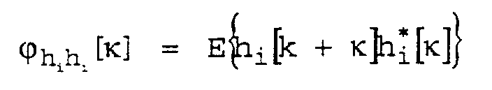

- The determination of the autocorrelation functions and variances σ 2 / h,i and σ 2 / n,i can be performed in the receiver, for example with the aid of the channel estimates. It is to be noted that σ 2 / i is a function of the power control factor s to be tested, and the correlation coefficient ρi is, furthermore, a function of a[0] and a[1].
- Furthermore, consideration will be given for what follows to the case of white noise ni[k], that is to say, ϕn
i ni [κ] = 0, κ ≠ 0 which case mostly obtains in practice to a good approximation. This leads to - A vector (or else scalar)
- Although it is also possible in principle to use criteria known to the person skilled in the art to estimate the factor s, a maximum a-posteriori approach is used below for the exemplary description. The estimated factor is therefore determined in accordance withp(s|u0, u1,..., uL-1)

denoting the conditional probability density function of s with u0, u1, ..., uL-1 being known. - Bayes' theorem is used to obtain the expression which is accessible for numerical evaluations, that is to say:

- Equation (13) is to be evaluated in this case for all possibilities, that is to say hypotheses for the factor s. Here, p(u0,u1,...,uL-1) can be neglected as an irrelevant factor for determining the most likely value, and the calculations of the a-priori probabilities Pr(s) can be carried out in a simple way with the aid of the error probabilities relating to the symbols containing the power control information. Furthermore, the overall density p(u0,u1,...,uL-1|s) to be calculated can be simplified. Since the channel coefficients hi[k] for various rake fingers F0, Fi, FL-1 can be modelled in a fashion statistically independent of one another, as can the interference processes ni[k], it is possible with a suitable selection of the function f(.) to assume the validity of the factorization
- A first possibility, without the need to know training frequencies on the part of the receiver, consists in forming the squares of absolute values component by component, that is to say

- Furthermore, the number of the symbols is selected as M=2, and binary antipodal modulation is assumed, such as is used, for example, in UMTS systems, that is to say a[k]∈{±1}. The representationis selected for calculating p(ui|s).

- The calculation of an overall probability density function of the squares of absolute values of two correlated complex Gaussian random variables, the calculation of p(ui=f(yi)|s,a[0],a[1]) in the case under consideration, proves to be a standard problem for the case of a two-dimensional complex Gaussian density for yi for given s, a[0] and a[1]; its solution is known from the literature, for example from publications by M. Schwartz et al. "Communication Systems and Techniques", McGraw-Hill, New York 1966 and by C.W. Helstrom, "The Resolution of Signals in White, Gaussian Noise", Proceedings of the IRE, 43:1111-1118, Sept. 1955. With σ 2 / i and ρi in accordance with equation (6) and equation (10) respectively, and the modified Bessel function of first kind of zero orderthe result is
 compare, for example, the abovementioned publication by M. Schwartz et al. In accordance with equation (10), the absolute value of ρi is independent of a[0] and a[1] for binary antipodal modulation and white noise. This results in accordance with equations (16) and (17) in
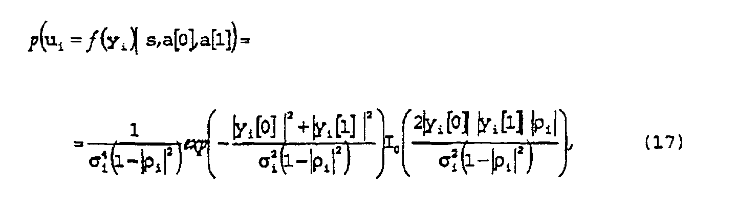 where
where
- A simplification can be undertaken given low signal-to-noise ratios, which occur as a rule at the outputs of the individual rake fingers F0, Fi, FL-1. Use may be made in this case of the approximationsupplementary reference being made for this purpose by way of example to the publication by D. Raphaeli, "Noncoherent Coded Modulation", Transactions on Communications, COM-44:172-183, Feb. 1996. Finally, using equation (13) and equation (14) the estimated power control factor s is yielded as that value which maximizes the expression


- As a second possibility, the squares of the absolute values of the individual received values can be summed to form the function f(.), that is to say

- M = 2 is chosen again by way of example, and the case of binary antipodal modulation is considered. The conditional density function of ui=f(yi) for a given s can be derived starting from the publication by M. Schwartz already referred to. Once again, the expression independent of a[0] and a[1] is yielded for the conditional density p(f(ui)|s,a[0],a[1]), leading finally toequations (20) and (21) holding, respectively, in turn for σ 2 / i and |ρi|. Starting therefrom, it is therefore possible to use equations (13) and (14) to specify directly the target function to be maximized as a function of s, more specifically


- A further preferred possibility consists in directly using yi to estimate s, that is to say, ui = yi in the case of the occurrence of training symbols, known at the receiving end, at the points k∈{0,1,...,M-1}. The case of M = 2 and a[0] = a[1] = 1 will be considered as an example. The resulting conditional density function iswhere

- Equations (13) and (14) can therefore be used to set up the target function, which is to be maximized as a function of s, as

- Whereas the above exclusively considered the case of considering only signal values of the new receiving block n+1 to estimate s, that is to say after a change in the power control factor s, an estimate can also be made by additionally considering received values of the old block n. As an example, the use of received values from an old and a new receiving block n and n+1, respectively, are considered (Figure 4) below for this purpose, that is to say in the case of M=2 the received vector relating to the ith rake finger Fi is formed asIt is assumed, furthermore, that the compensation of the power control factor s has already been undertaken for the old received value. A Gaussian density in accordance with equation (4) is yielded once again as conditional density p(yi|s,a[-1],a[0]), the result for the autocorrelation matrix now being
 Here, s0 denotes the already determined power control factor of the old block n. As a person skilled in the art in this field will recognize, it is therefore possible to use this result once again to derive target functions for estimating s for the three possibilities discussed above which are based on function f(.) and binary antipodal modulation.
- In a practical implementation, in particular inside a receiver of a CDMA-based mobile radio system, the method entails only a slight extra outlay and is started in relation to any period of the power control. After the storage of the samples yi[k] for all L rake fingers, the latter are therefore additionally preprocessed with the formation of the function f(.) based, in particular, on one of the three preferred possibilities described above.
- Consequently, it is subsequently possible in conjunction with consideration of the a-priori probability Pr(s) for the occurrence of a power control factor s which is known per se from a transmitted power control command and the uncoded error rate then to set up a target function for all possible power control factors s, it being possible to use samples from a receiving block n+1 or, alternatively, received values from different blocks n, n+1 (Figure 4): for example, when selecting the number of symbols to be considered in relation to M=2, either the samples yi[0] and yi[1] from the new receiving block n+1 or, alternatively, the samples yi[-1] and Yi[0] from different receiving blocks. The estimate for the power control factor s actually occurring is thereupon selected as that for which the target function can be maximized.
- The method according to the invention for estimating the correction factor can therefore be performed both with the aid of received values which are assigned to pilot symbols, and with the aid of received values which are assigned to unknown data.
- The method according to the invention ensures enhancement of the quality of the parameter estimation, thus ensuring a reduction in the bit error rate of the transmission system and/or in a possible saving of necessary transmit power.
Claims (18)
- Method for improving the reception of a CDMA receiver based on a parameter estimation method, in which the estimates are produced by processing received values (yi[k]) provided with correction factors (s), the correction factors (s) serving to equalize different power levels of the received signal.
- Method according to Claim 1, characterized in that the discontinuity of transmit power levels and the correction factors (s) resulting therefrom are estimated using methods of the statistical hypothesis test and are assigned to the received values (yi[k]).
- Method according to Claim 1 or 2, characterized in that the a-priori probability (Pr(s)) for the presence of a specific discontinuity of a transmit power level is used in the case of a method of the statistical hypothesis test to improve the estimation of the current discontinuity of the transmit power level of the received signal (yi[k]).
- Method according to one of the preceding claims, characterized in that the estimation of a power control factor (s) provides parameters which reproduce the currently estimated discontinuity of the transmit power of a mobile station.
- Method according to one of the preceding claims, characterized in that the parameter estimation method undertakes to estimate the discontinuity of the transmit power between two blocks (n, n+1) respectively assigned to a transmit power.
- Method according to one of Claims 1 to 5, characterized in that in order to estimate the correction factor, the parameter estimation method uses a vector from component-by-component squares of absolute values of the received signal (yi[k]) to carry out the statistical hypothesis test.
- Method according to one of Claims 1 to 6, characterized in that sums of squares of absolute values are used to carry out the statistical hypothesis test.
- Method according to one of the preceding claims, characterized in that the statistical hypothesis test is carried out during the reception of received values (yi[k]) corresponding to training symbols.
- Method according to one of Claims 1 to 6, characterized in that only received values (yi[k]) from the block (n+1) belonging to the power control factor (s) currently to be estimated are used to estimate the power level.
- Method according to one of Claims 1 to 9, characterized in that received values (yi[k]) from the block (n+1) belonging to the power control factor (s) currently to be estimated, and from the preceding block (n) are used to estimate the power level.
- Method according to one of the preceding claims, characterized in that in the event of a discontinuity the estimation of discontinuities of the power control factors (s) signals further estimation methods and is used as a basis for the latter.
- Method according to Claim 11, characterized in that the further estimation methods cover the estimation of properties of the transmission channel.
- Method according to Claim 12, characterized in that the further estimation methods cover the estimation of the transmitted bit stream.
- CDMA receiver comprising a parameter estimation device for carrying out a parameter estimation method in accordance with one of Claims 1 to 13.
- CDMA receiver according to Claim 14, characterized in that the receiver is designed as a rake receiver.
- CDMA receiver according to Claim 15, characterized in that more than one finger (F0, Fi, FL-1) of the rake receiver are assigned a parameter estimation device (5).
- CDMA receiver according to Claim 15 or 16, characterized in that signals from more than one finger (F0, Fi, FL-1) of the rake receiver are used to carry out the statistical hypothesis test.
- Implementation program for carrying out a method according to one of Claims 1 to 13, in particular inside a CDMA receiver according to one of Claims 14 to 17.
Priority Applications (4)
| Application Number | Priority Date | Filing Date | Title |
|---|---|---|---|
| DE60107932T DE60107932T2 (en) | 2001-05-29 | 2001-05-29 | Method for improving the reception of a CDMA receiver and CDMA receiver thereto |
| EP01304709A EP1265384B1 (en) | 2001-05-29 | 2001-05-29 | Method for improving the reception of a CDMA receiver, and corresponding CDMA receiver |
| US10/134,843 US7280499B2 (en) | 2001-05-29 | 2002-04-29 | Method for improving the reception of a CDMA receiver, and a CDMA receiver with improved reception |
| JP2002147976A JP4050552B2 (en) | 2001-05-29 | 2002-05-22 | Method for improving the reception of a CDMA receiver |
Applications Claiming Priority (1)
| Application Number | Priority Date | Filing Date | Title |
|---|---|---|---|
| EP01304709A EP1265384B1 (en) | 2001-05-29 | 2001-05-29 | Method for improving the reception of a CDMA receiver, and corresponding CDMA receiver |
Publications (2)
| Publication Number | Publication Date |
|---|---|
| EP1265384A1 true EP1265384A1 (en) | 2002-12-11 |
| EP1265384B1 EP1265384B1 (en) | 2004-12-22 |
Family
ID=8181994
Family Applications (1)
| Application Number | Title | Priority Date | Filing Date |
|---|---|---|---|
| EP01304709A Expired - Lifetime EP1265384B1 (en) | 2001-05-29 | 2001-05-29 | Method for improving the reception of a CDMA receiver, and corresponding CDMA receiver |
Country Status (4)
| Country | Link |
|---|---|
| US (1) | US7280499B2 (en) |
| EP (1) | EP1265384B1 (en) |
| JP (1) | JP4050552B2 (en) |
| DE (1) | DE60107932T2 (en) |
Families Citing this family (4)
| Publication number | Priority date | Publication date | Assignee | Title |
|---|---|---|---|---|
| US6816470B2 (en) | 2001-09-18 | 2004-11-09 | Interdigital Technology Corporation | Method and apparatus for interference signal code power and noise variance estimation |
| US20040030530A1 (en) * | 2002-01-30 | 2004-02-12 | Kuo-Hui Li | Apparatus and method for detection of direct sequence spread spectrum signals in networking systems |
| WO2004095713A2 (en) * | 2003-04-14 | 2004-11-04 | Bae Systems Information And Electronic Systems Integration Inc. | Joint symbol, amplitude, and rate estimator |
| CN1926777A (en) * | 2004-03-24 | 2007-03-07 | 意大利电信股份公司 | Method and system for channel estimation, relating receiver and computer program product |
Citations (5)
| Publication number | Priority date | Publication date | Assignee | Title |
|---|---|---|---|---|
| US5799011A (en) * | 1996-03-29 | 1998-08-25 | Motorola, Inc. | CDMA power control channel estimation using dynamic coefficient scaling |
| EP0893888A2 (en) * | 1997-07-25 | 1999-01-27 | Kabushiki Kaisha Toshiba | Spread spectrum communication apparatus and rake receiver |
| WO2000033472A1 (en) * | 1998-12-03 | 2000-06-08 | Ericsson, Inc. | Digital receivers and receiving methods that scale for relative strengths of traffic and pilot channels during soft handoff |
| US6208632B1 (en) * | 1998-01-29 | 2001-03-27 | Sharp Laboratories Of America | System and method for CDMA channel estimation |
| EP1158696A2 (en) * | 2000-05-24 | 2001-11-28 | NTT DoCoMo, Inc. | Method of antenna-weight estimation |
Family Cites Families (1)
| Publication number | Priority date | Publication date | Assignee | Title |
|---|---|---|---|---|
| US6104747A (en) * | 1998-11-30 | 2000-08-15 | Motorola, Inc. | Method for determining optimum number of complex samples for coherent averaging in a communication system |
-
2001
- 2001-05-29 DE DE60107932T patent/DE60107932T2/en not_active Expired - Lifetime
- 2001-05-29 EP EP01304709A patent/EP1265384B1/en not_active Expired - Lifetime
-
2002
- 2002-04-29 US US10/134,843 patent/US7280499B2/en not_active Expired - Fee Related
- 2002-05-22 JP JP2002147976A patent/JP4050552B2/en not_active Expired - Fee Related
Patent Citations (5)
| Publication number | Priority date | Publication date | Assignee | Title |
|---|---|---|---|---|
| US5799011A (en) * | 1996-03-29 | 1998-08-25 | Motorola, Inc. | CDMA power control channel estimation using dynamic coefficient scaling |
| EP0893888A2 (en) * | 1997-07-25 | 1999-01-27 | Kabushiki Kaisha Toshiba | Spread spectrum communication apparatus and rake receiver |
| US6208632B1 (en) * | 1998-01-29 | 2001-03-27 | Sharp Laboratories Of America | System and method for CDMA channel estimation |
| WO2000033472A1 (en) * | 1998-12-03 | 2000-06-08 | Ericsson, Inc. | Digital receivers and receiving methods that scale for relative strengths of traffic and pilot channels during soft handoff |
| EP1158696A2 (en) * | 2000-05-24 | 2001-11-28 | NTT DoCoMo, Inc. | Method of antenna-weight estimation |
Non-Patent Citations (1)
| Title |
|---|
| CHEN Y H ET AL: "CORRELATION STATISTICS DISTRIBUTION CONVOLUTION (CSDC) MODELING FORSTUDYING CDMA INDOOR WIRELESS SYSTEMS WITH RAKE RECEIVER, POWER CONTROL & MULTIPATH FADING", IEICE TRANSACTIONS ON COMMUNICATIONS, INSTITUTE OF ELECTRONICS INFORMATION AND COMM. ENG. TOKYO, JP, vol. E79B, no. 10, 1 October 1996 (1996-10-01), pages 1525 - 1535, XP000636095, ISSN: 0916-8516 * |
Also Published As
| Publication number | Publication date |
|---|---|
| US7280499B2 (en) | 2007-10-09 |
| DE60107932D1 (en) | 2005-01-27 |
| EP1265384B1 (en) | 2004-12-22 |
| JP2003037581A (en) | 2003-02-07 |
| JP4050552B2 (en) | 2008-02-20 |
| DE60107932T2 (en) | 2005-12-08 |
| US20030031237A1 (en) | 2003-02-13 |
Similar Documents
| Publication | Publication Date | Title |
|---|---|---|
| EP0944977B1 (en) | Method and apparatus for digital symbol detection using transmission medium response estimates | |
| KR100297350B1 (en) | Interference stop coupling method and apparatus in multiple antenna digital cellular communication systems | |
| KR100568647B1 (en) | Determination of the length of a channel impulse response | |
| US7471749B2 (en) | Channel parameters estimation in a receiver | |
| EP1118165B1 (en) | Method and apparatus for interference cancellation in a rake receiver | |
| EP0784887B1 (en) | Signal detection in a tdma system | |
| RU2481742C2 (en) | Interference cancellation under non-stationary conditions | |
| EP1224780B1 (en) | Baseband processor with look-ahead parameter estimation capabilities | |
| KR101520362B1 (en) | Symbol estimation methods and apparatuses | |
| EP1210803B1 (en) | Determination of data rate, based on power spectral density estimates | |
| US6249518B1 (en) | TDMA single antenna co-channel interference cancellation | |
| JPH11168420A (en) | Adaptive receiver for cdma base station | |
| US20080205555A1 (en) | Method and Apparatus for Channel Estimation | |
| US6212243B1 (en) | Channel estimation performed at varying time intervals | |
| EP1265384B1 (en) | Method for improving the reception of a CDMA receiver, and corresponding CDMA receiver | |
| US20050118955A1 (en) | Method for prediction of a channel coefficient | |
| US6931054B2 (en) | Method for estimating channel parameters of radio channels of a W-CDMA mobile radio system | |
| US7929629B2 (en) | Method and apparatus for improved channel estimation for communications signal processing | |
| EP1195032B1 (en) | Method for symbol-spaced estimation and/or tracking of a fractionally-spaced fading radio channel | |
| JP2003087167A (en) | Method and device for estimating speed of mobile terminal | |
| US20100040176A1 (en) | Channel Impulse Response Estimate Management | |
| WO2001073993A1 (en) | Communication device and communication method | |
| EP1714511A1 (en) | Method of optimising planning in a cdma-type communications system | |
| US7257180B2 (en) | Method for receiving a message signal, receiver, receiving device and message transmission system for this | |
| Spasojevic et al. | Implicit diversity combining based on the EM algorithm for fading channels with correlated path components |
Legal Events
| Date | Code | Title | Description |
|---|---|---|---|
| PUAI | Public reference made under article 153(3) epc to a published international application that has entered the european phase |
Free format text: ORIGINAL CODE: 0009012 |
|
| AK | Designated contracting states |
Kind code of ref document: A1 Designated state(s): AT BE CH CY DE DK ES FI FR GB GR IE IT LI LU MC NL PT SE TR |
|
| AX | Request for extension of the european patent |
Free format text: AL;LT;LV;MK;RO;SI |
|
| 17P | Request for examination filed |
Effective date: 20030531 |
|
| AKX | Designation fees paid |
Designated state(s): DE FR GB |
|
| 17Q | First examination report despatched |
Effective date: 20030820 |
|
| GRAP | Despatch of communication of intention to grant a patent |
Free format text: ORIGINAL CODE: EPIDOSNIGR1 |
|
| GRAS | Grant fee paid |
Free format text: ORIGINAL CODE: EPIDOSNIGR3 |
|
| GRAA | (expected) grant |
Free format text: ORIGINAL CODE: 0009210 |
|
| AK | Designated contracting states |
Kind code of ref document: B1 Designated state(s): DE FR GB |
|
| REG | Reference to a national code |
Ref country code: GB Ref legal event code: FG4D |
|
| REG | Reference to a national code |
Ref country code: IE Ref legal event code: FG4D |
|
| REF | Corresponds to: |
Ref document number: 60107932 Country of ref document: DE Date of ref document: 20050127 Kind code of ref document: P |
|
| PLBE | No opposition filed within time limit |
Free format text: ORIGINAL CODE: 0009261 |
|
| STAA | Information on the status of an ep patent application or granted ep patent |
Free format text: STATUS: NO OPPOSITION FILED WITHIN TIME LIMIT |
|
| ET | Fr: translation filed | ||
| 26N | No opposition filed |
Effective date: 20050923 |
|
| REG | Reference to a national code |
Ref country code: GB Ref legal event code: 732E Free format text: REGISTERED BETWEEN 20131031 AND 20131106 |
|
| REG | Reference to a national code |
Ref country code: FR Ref legal event code: CD Owner name: ALCATEL-LUCENT USA INC. Effective date: 20131122 |
|
| REG | Reference to a national code |
Ref country code: FR Ref legal event code: GC Effective date: 20140410 |
|
| REG | Reference to a national code |
Ref country code: FR Ref legal event code: RG Effective date: 20141015 |
|
| REG | Reference to a national code |
Ref country code: FR Ref legal event code: PLFP Year of fee payment: 15 |
|
| PGFP | Annual fee paid to national office [announced via postgrant information from national office to epo] |
Ref country code: GB Payment date: 20150521 Year of fee payment: 15 Ref country code: DE Payment date: 20150521 Year of fee payment: 15 |
|
| PGFP | Annual fee paid to national office [announced via postgrant information from national office to epo] |
Ref country code: FR Payment date: 20150521 Year of fee payment: 15 |
|
| REG | Reference to a national code |
Ref country code: DE Ref legal event code: R119 Ref document number: 60107932 Country of ref document: DE |
|
| GBPC | Gb: european patent ceased through non-payment of renewal fee |
Effective date: 20160529 |
|
| REG | Reference to a national code |
Ref country code: FR Ref legal event code: ST Effective date: 20170131 |
|
| PG25 | Lapsed in a contracting state [announced via postgrant information from national office to epo] |
Ref country code: FR Free format text: LAPSE BECAUSE OF NON-PAYMENT OF DUE FEES Effective date: 20160531 Ref country code: DE Free format text: LAPSE BECAUSE OF NON-PAYMENT OF DUE FEES Effective date: 20161201 |
|
| PG25 | Lapsed in a contracting state [announced via postgrant information from national office to epo] |
Ref country code: GB Free format text: LAPSE BECAUSE OF NON-PAYMENT OF DUE FEES Effective date: 20160529 |