EP1266638B1 - Balloon-actuated stent with interlocking elements - Google Patents
Balloon-actuated stent with interlocking elements Download PDFInfo
- Publication number
- EP1266638B1 EP1266638B1 EP02253789A EP02253789A EP1266638B1 EP 1266638 B1 EP1266638 B1 EP 1266638B1 EP 02253789 A EP02253789 A EP 02253789A EP 02253789 A EP02253789 A EP 02253789A EP 1266638 B1 EP1266638 B1 EP 1266638B1
- Authority
- EP
- European Patent Office
- Prior art keywords
- stent
- projection
- expandable member
- configuration
- catheter
- Prior art date
- Legal status (The legal status is an assumption and is not a legal conclusion. Google has not performed a legal analysis and makes no representation as to the accuracy of the status listed.)
- Expired - Lifetime
Links
- 229910045601 alloy Inorganic materials 0.000 claims description 12
- 239000000956 alloy Substances 0.000 claims description 12
- HZEWFHLRYVTOIW-UHFFFAOYSA-N [Ti].[Ni] Chemical compound [Ti].[Ni] HZEWFHLRYVTOIW-UHFFFAOYSA-N 0.000 claims description 6
- 229910001000 nickel titanium Inorganic materials 0.000 claims description 6
- 229910001220 stainless steel Inorganic materials 0.000 claims description 3
- 239000010935 stainless steel Substances 0.000 claims description 3
- 229920000642 polymer Polymers 0.000 claims 1
- 238000000034 method Methods 0.000 abstract description 19
- 238000013461 design Methods 0.000 description 7
- 239000000463 material Substances 0.000 description 6
- 210000004204 blood vessel Anatomy 0.000 description 3
- 238000003780 insertion Methods 0.000 description 3
- 230000037431 insertion Effects 0.000 description 3
- 229910052751 metal Inorganic materials 0.000 description 3
- 239000002184 metal Substances 0.000 description 3
- 230000003319 supportive effect Effects 0.000 description 3
- 239000010936 titanium Substances 0.000 description 3
- 230000002792 vascular Effects 0.000 description 3
- 238000002399 angioplasty Methods 0.000 description 2
- 210000001367 artery Anatomy 0.000 description 2
- 229910052759 nickel Inorganic materials 0.000 description 2
- PXHVJJICTQNCMI-UHFFFAOYSA-N nickel Substances [Ni] PXHVJJICTQNCMI-UHFFFAOYSA-N 0.000 description 2
- 210000000056 organ Anatomy 0.000 description 2
- 239000002861 polymer material Substances 0.000 description 2
- 230000002787 reinforcement Effects 0.000 description 2
- 229910052719 titanium Inorganic materials 0.000 description 2
- 210000003462 vein Anatomy 0.000 description 2
- 206010002329 Aneurysm Diseases 0.000 description 1
- 206010028980 Neoplasm Diseases 0.000 description 1
- 208000031481 Pathologic Constriction Diseases 0.000 description 1
- 239000004698 Polyethylene Substances 0.000 description 1
- RTAQQCXQSZGOHL-UHFFFAOYSA-N Titanium Chemical compound [Ti] RTAQQCXQSZGOHL-UHFFFAOYSA-N 0.000 description 1
- 210000000013 bile duct Anatomy 0.000 description 1
- 239000008280 blood Substances 0.000 description 1
- 210000004369 blood Anatomy 0.000 description 1
- 210000001124 body fluid Anatomy 0.000 description 1
- 230000036760 body temperature Effects 0.000 description 1
- 210000001715 carotid artery Anatomy 0.000 description 1
- 238000010276 construction Methods 0.000 description 1
- 210000004351 coronary vessel Anatomy 0.000 description 1
- 238000002788 crimping Methods 0.000 description 1
- 230000007547 defect Effects 0.000 description 1
- 210000003238 esophagus Anatomy 0.000 description 1
- 210000001105 femoral artery Anatomy 0.000 description 1
- 239000012530 fluid Substances 0.000 description 1
- PCHJSUWPFVWCPO-UHFFFAOYSA-N gold Chemical compound [Au] PCHJSUWPFVWCPO-UHFFFAOYSA-N 0.000 description 1
- 239000010931 gold Substances 0.000 description 1
- 229910052737 gold Inorganic materials 0.000 description 1
- 210000002989 hepatic vein Anatomy 0.000 description 1
- 238000011065 in-situ storage Methods 0.000 description 1
- 210000000936 intestine Anatomy 0.000 description 1
- 230000003902 lesion Effects 0.000 description 1
- 238000004519 manufacturing process Methods 0.000 description 1
- 150000002739 metals Chemical class 0.000 description 1
- 238000013508 migration Methods 0.000 description 1
- 230000005012 migration Effects 0.000 description 1
- 229920003023 plastic Polymers 0.000 description 1
- 239000004033 plastic Substances 0.000 description 1
- -1 polyethylene Polymers 0.000 description 1
- 229920000573 polyethylene Polymers 0.000 description 1
- 210000003137 popliteal artery Anatomy 0.000 description 1
- 208000007232 portal hypertension Diseases 0.000 description 1
- 210000003240 portal vein Anatomy 0.000 description 1
- 230000002028 premature Effects 0.000 description 1
- 208000037803 restenosis Diseases 0.000 description 1
- 229910052709 silver Inorganic materials 0.000 description 1
- 239000004332 silver Substances 0.000 description 1
- 229910001256 stainless steel alloy Inorganic materials 0.000 description 1
- 230000036262 stenosis Effects 0.000 description 1
- 208000037804 stenosis Diseases 0.000 description 1
- 230000002966 stenotic effect Effects 0.000 description 1
- 229910052715 tantalum Inorganic materials 0.000 description 1
- GUVRBAGPIYLISA-UHFFFAOYSA-N tantalum atom Chemical compound [Ta] GUVRBAGPIYLISA-UHFFFAOYSA-N 0.000 description 1
- 210000000626 ureter Anatomy 0.000 description 1
- 230000003245 working effect Effects 0.000 description 1
Images


Classifications
-
- A—HUMAN NECESSITIES
- A61—MEDICAL OR VETERINARY SCIENCE; HYGIENE
- A61F—FILTERS IMPLANTABLE INTO BLOOD VESSELS; PROSTHESES; DEVICES PROVIDING PATENCY TO, OR PREVENTING COLLAPSING OF, TUBULAR STRUCTURES OF THE BODY, e.g. STENTS; ORTHOPAEDIC, NURSING OR CONTRACEPTIVE DEVICES; FOMENTATION; TREATMENT OR PROTECTION OF EYES OR EARS; BANDAGES, DRESSINGS OR ABSORBENT PADS; FIRST-AID KITS
- A61F2/00—Filters implantable into blood vessels; Prostheses, i.e. artificial substitutes or replacements for parts of the body; Appliances for connecting them with the body; Devices providing patency to, or preventing collapsing of, tubular structures of the body, e.g. stents
- A61F2/95—Instruments specially adapted for placement or removal of stents or stent-grafts
- A61F2/958—Inflatable balloons for placing stents or stent-grafts
-
- A—HUMAN NECESSITIES
- A61—MEDICAL OR VETERINARY SCIENCE; HYGIENE
- A61F—FILTERS IMPLANTABLE INTO BLOOD VESSELS; PROSTHESES; DEVICES PROVIDING PATENCY TO, OR PREVENTING COLLAPSING OF, TUBULAR STRUCTURES OF THE BODY, e.g. STENTS; ORTHOPAEDIC, NURSING OR CONTRACEPTIVE DEVICES; FOMENTATION; TREATMENT OR PROTECTION OF EYES OR EARS; BANDAGES, DRESSINGS OR ABSORBENT PADS; FIRST-AID KITS
- A61F2/00—Filters implantable into blood vessels; Prostheses, i.e. artificial substitutes or replacements for parts of the body; Appliances for connecting them with the body; Devices providing patency to, or preventing collapsing of, tubular structures of the body, e.g. stents
- A61F2/82—Devices providing patency to, or preventing collapsing of, tubular structures of the body, e.g. stents
- A61F2/86—Stents in a form characterised by the wire-like elements; Stents in the form characterised by a net-like or mesh-like structure
- A61F2/90—Stents in a form characterised by the wire-like elements; Stents in the form characterised by a net-like or mesh-like structure characterised by a net-like or mesh-like structure
- A61F2/91—Stents in a form characterised by the wire-like elements; Stents in the form characterised by a net-like or mesh-like structure characterised by a net-like or mesh-like structure made from perforated sheet material or tubes, e.g. perforated by laser cuts or etched holes
- A61F2/915—Stents in a form characterised by the wire-like elements; Stents in the form characterised by a net-like or mesh-like structure characterised by a net-like or mesh-like structure made from perforated sheet material or tubes, e.g. perforated by laser cuts or etched holes with bands having a meander structure, adjacent bands being connected to each other
-
- A—HUMAN NECESSITIES
- A61—MEDICAL OR VETERINARY SCIENCE; HYGIENE
- A61F—FILTERS IMPLANTABLE INTO BLOOD VESSELS; PROSTHESES; DEVICES PROVIDING PATENCY TO, OR PREVENTING COLLAPSING OF, TUBULAR STRUCTURES OF THE BODY, e.g. STENTS; ORTHOPAEDIC, NURSING OR CONTRACEPTIVE DEVICES; FOMENTATION; TREATMENT OR PROTECTION OF EYES OR EARS; BANDAGES, DRESSINGS OR ABSORBENT PADS; FIRST-AID KITS
- A61F2/00—Filters implantable into blood vessels; Prostheses, i.e. artificial substitutes or replacements for parts of the body; Appliances for connecting them with the body; Devices providing patency to, or preventing collapsing of, tubular structures of the body, e.g. stents
- A61F2/82—Devices providing patency to, or preventing collapsing of, tubular structures of the body, e.g. stents
- A61F2/86—Stents in a form characterised by the wire-like elements; Stents in the form characterised by a net-like or mesh-like structure
- A61F2/90—Stents in a form characterised by the wire-like elements; Stents in the form characterised by a net-like or mesh-like structure characterised by a net-like or mesh-like structure
- A61F2/91—Stents in a form characterised by the wire-like elements; Stents in the form characterised by a net-like or mesh-like structure characterised by a net-like or mesh-like structure made from perforated sheet material or tubes, e.g. perforated by laser cuts or etched holes
-
- A—HUMAN NECESSITIES
- A61—MEDICAL OR VETERINARY SCIENCE; HYGIENE
- A61F—FILTERS IMPLANTABLE INTO BLOOD VESSELS; PROSTHESES; DEVICES PROVIDING PATENCY TO, OR PREVENTING COLLAPSING OF, TUBULAR STRUCTURES OF THE BODY, e.g. STENTS; ORTHOPAEDIC, NURSING OR CONTRACEPTIVE DEVICES; FOMENTATION; TREATMENT OR PROTECTION OF EYES OR EARS; BANDAGES, DRESSINGS OR ABSORBENT PADS; FIRST-AID KITS
- A61F2/00—Filters implantable into blood vessels; Prostheses, i.e. artificial substitutes or replacements for parts of the body; Appliances for connecting them with the body; Devices providing patency to, or preventing collapsing of, tubular structures of the body, e.g. stents
- A61F2/95—Instruments specially adapted for placement or removal of stents or stent-grafts
- A61F2/962—Instruments specially adapted for placement or removal of stents or stent-grafts having an outer sleeve
-
- A—HUMAN NECESSITIES
- A61—MEDICAL OR VETERINARY SCIENCE; HYGIENE
- A61L—METHODS OR APPARATUS FOR STERILISING MATERIALS OR OBJECTS IN GENERAL; DISINFECTION, STERILISATION OR DEODORISATION OF AIR; CHEMICAL ASPECTS OF BANDAGES, DRESSINGS, ABSORBENT PADS OR SURGICAL ARTICLES; MATERIALS FOR BANDAGES, DRESSINGS, ABSORBENT PADS OR SURGICAL ARTICLES
- A61L27/00—Materials for grafts or prostheses or for coating grafts or prostheses
- A61L27/02—Inorganic materials
- A61L27/04—Metals or alloys
-
- A—HUMAN NECESSITIES
- A61—MEDICAL OR VETERINARY SCIENCE; HYGIENE
- A61M—DEVICES FOR INTRODUCING MEDIA INTO, OR ONTO, THE BODY; DEVICES FOR TRANSDUCING BODY MEDIA OR FOR TAKING MEDIA FROM THE BODY; DEVICES FOR PRODUCING OR ENDING SLEEP OR STUPOR
- A61M25/00—Catheters; Hollow probes
- A61M25/10—Balloon catheters
-
- A—HUMAN NECESSITIES
- A61—MEDICAL OR VETERINARY SCIENCE; HYGIENE
- A61F—FILTERS IMPLANTABLE INTO BLOOD VESSELS; PROSTHESES; DEVICES PROVIDING PATENCY TO, OR PREVENTING COLLAPSING OF, TUBULAR STRUCTURES OF THE BODY, e.g. STENTS; ORTHOPAEDIC, NURSING OR CONTRACEPTIVE DEVICES; FOMENTATION; TREATMENT OR PROTECTION OF EYES OR EARS; BANDAGES, DRESSINGS OR ABSORBENT PADS; FIRST-AID KITS
- A61F2/00—Filters implantable into blood vessels; Prostheses, i.e. artificial substitutes or replacements for parts of the body; Appliances for connecting them with the body; Devices providing patency to, or preventing collapsing of, tubular structures of the body, e.g. stents
- A61F2/82—Devices providing patency to, or preventing collapsing of, tubular structures of the body, e.g. stents
- A61F2/86—Stents in a form characterised by the wire-like elements; Stents in the form characterised by a net-like or mesh-like structure
- A61F2/90—Stents in a form characterised by the wire-like elements; Stents in the form characterised by a net-like or mesh-like structure characterised by a net-like or mesh-like structure
- A61F2/91—Stents in a form characterised by the wire-like elements; Stents in the form characterised by a net-like or mesh-like structure characterised by a net-like or mesh-like structure made from perforated sheet material or tubes, e.g. perforated by laser cuts or etched holes
- A61F2/915—Stents in a form characterised by the wire-like elements; Stents in the form characterised by a net-like or mesh-like structure characterised by a net-like or mesh-like structure made from perforated sheet material or tubes, e.g. perforated by laser cuts or etched holes with bands having a meander structure, adjacent bands being connected to each other
- A61F2002/91533—Stents in a form characterised by the wire-like elements; Stents in the form characterised by a net-like or mesh-like structure characterised by a net-like or mesh-like structure made from perforated sheet material or tubes, e.g. perforated by laser cuts or etched holes with bands having a meander structure, adjacent bands being connected to each other characterised by the phase between adjacent bands
-
- A—HUMAN NECESSITIES
- A61—MEDICAL OR VETERINARY SCIENCE; HYGIENE
- A61F—FILTERS IMPLANTABLE INTO BLOOD VESSELS; PROSTHESES; DEVICES PROVIDING PATENCY TO, OR PREVENTING COLLAPSING OF, TUBULAR STRUCTURES OF THE BODY, e.g. STENTS; ORTHOPAEDIC, NURSING OR CONTRACEPTIVE DEVICES; FOMENTATION; TREATMENT OR PROTECTION OF EYES OR EARS; BANDAGES, DRESSINGS OR ABSORBENT PADS; FIRST-AID KITS
- A61F2/00—Filters implantable into blood vessels; Prostheses, i.e. artificial substitutes or replacements for parts of the body; Appliances for connecting them with the body; Devices providing patency to, or preventing collapsing of, tubular structures of the body, e.g. stents
- A61F2/82—Devices providing patency to, or preventing collapsing of, tubular structures of the body, e.g. stents
- A61F2/86—Stents in a form characterised by the wire-like elements; Stents in the form characterised by a net-like or mesh-like structure
- A61F2/90—Stents in a form characterised by the wire-like elements; Stents in the form characterised by a net-like or mesh-like structure characterised by a net-like or mesh-like structure
- A61F2/91—Stents in a form characterised by the wire-like elements; Stents in the form characterised by a net-like or mesh-like structure characterised by a net-like or mesh-like structure made from perforated sheet material or tubes, e.g. perforated by laser cuts or etched holes
- A61F2/915—Stents in a form characterised by the wire-like elements; Stents in the form characterised by a net-like or mesh-like structure characterised by a net-like or mesh-like structure made from perforated sheet material or tubes, e.g. perforated by laser cuts or etched holes with bands having a meander structure, adjacent bands being connected to each other
- A61F2002/9155—Adjacent bands being connected to each other
- A61F2002/91558—Adjacent bands being connected to each other connected peak to peak
-
- A—HUMAN NECESSITIES
- A61—MEDICAL OR VETERINARY SCIENCE; HYGIENE
- A61F—FILTERS IMPLANTABLE INTO BLOOD VESSELS; PROSTHESES; DEVICES PROVIDING PATENCY TO, OR PREVENTING COLLAPSING OF, TUBULAR STRUCTURES OF THE BODY, e.g. STENTS; ORTHOPAEDIC, NURSING OR CONTRACEPTIVE DEVICES; FOMENTATION; TREATMENT OR PROTECTION OF EYES OR EARS; BANDAGES, DRESSINGS OR ABSORBENT PADS; FIRST-AID KITS
- A61F2/00—Filters implantable into blood vessels; Prostheses, i.e. artificial substitutes or replacements for parts of the body; Appliances for connecting them with the body; Devices providing patency to, or preventing collapsing of, tubular structures of the body, e.g. stents
- A61F2/82—Devices providing patency to, or preventing collapsing of, tubular structures of the body, e.g. stents
- A61F2/86—Stents in a form characterised by the wire-like elements; Stents in the form characterised by a net-like or mesh-like structure
- A61F2/90—Stents in a form characterised by the wire-like elements; Stents in the form characterised by a net-like or mesh-like structure characterised by a net-like or mesh-like structure
- A61F2/91—Stents in a form characterised by the wire-like elements; Stents in the form characterised by a net-like or mesh-like structure characterised by a net-like or mesh-like structure made from perforated sheet material or tubes, e.g. perforated by laser cuts or etched holes
- A61F2/915—Stents in a form characterised by the wire-like elements; Stents in the form characterised by a net-like or mesh-like structure characterised by a net-like or mesh-like structure made from perforated sheet material or tubes, e.g. perforated by laser cuts or etched holes with bands having a meander structure, adjacent bands being connected to each other
- A61F2002/9155—Adjacent bands being connected to each other
- A61F2002/91591—Locking connectors, e.g. using male-female connections
-
- A—HUMAN NECESSITIES
- A61—MEDICAL OR VETERINARY SCIENCE; HYGIENE
- A61F—FILTERS IMPLANTABLE INTO BLOOD VESSELS; PROSTHESES; DEVICES PROVIDING PATENCY TO, OR PREVENTING COLLAPSING OF, TUBULAR STRUCTURES OF THE BODY, e.g. STENTS; ORTHOPAEDIC, NURSING OR CONTRACEPTIVE DEVICES; FOMENTATION; TREATMENT OR PROTECTION OF EYES OR EARS; BANDAGES, DRESSINGS OR ABSORBENT PADS; FIRST-AID KITS
- A61F2230/00—Geometry of prostheses classified in groups A61F2/00 - A61F2/26 or A61F2/82 or A61F9/00 or A61F11/00 or subgroups thereof
- A61F2230/0002—Two-dimensional shapes, e.g. cross-sections
- A61F2230/0028—Shapes in the form of latin or greek characters
- A61F2230/0054—V-shaped
Definitions
- the present invention relates, in general, to intraluminal medical devices, and, more particularly, to a new and useful stent, and stent delivery apparatus.
- a stent is commonly used as a tubular structure left inside the lumen of a duct to relieve an obstruction.
- stents are inserted into the lumen in a non-expanded form and are then expanded autonomously (or with the aid of a second device) in situ.
- stents are placed percutaneously through the femoral artery.
- stents are delivered on a catheter and are either self-expanding or, in the majority of cases, expanded by a balloon. Self-expanding stents do not need a balloon to be deployed.
- the stents are constructed using metals with spring-like or superelastic properties (especially nickel titanium based alloys), which inherently exhibit constant radial support.
- Self-expanding stents are also often used in vessels close to the skin (i.e., carotid arteries) or vessels that can experience a lot of movement (i.e., popliteal artery). Due to a natural elastic recoil, self-expanding stents withstand pressure or shifting and maintain their shape.
- the typical method of expansion for balloon expanded stents occurs through the use of a catheter mounted angioplasty balloon, which is inflated within the stenosed vessel or body passageway, in order to shear and disrupt the obstructions associated with the wall components of the vessel and to obtain an enlarged lumen.
- Balloon-expandable stents involve crimping the device onto an angioplasty balloon.
- the stent takes shape as the balloon is inflated and remains in place when the balloon and delivery system are deflated and removed.
- balloon-expandable stents are available either pre-mounted or unmounted.
- a pre-mounted system has the stent already crimped on a balloon, while an unmounted system gives the physician the option as to what combination of devices (catheters and stents) to use.
- the stent is first introduced into the blood vessel on a balloon catheter. Then, the balloon is inflated causing the stent to expand and press against the vessel wall. After expanding the stent, the balloon is deflated and withdrawn from the vessel together with the catheter. Once the balloon is withdrawn, the stent stays in place permanently, holding the vessel open and improving the flow of blood.
- the present invention relates to an apparatus and method for stenting a vessel in conjunction with a particular new and useful stent having a lattice of interconnecting elements defining a substantially cylindrical configuration.
- the lattice has a first open end and a second open end wherein the lattice is movable between a locked configuration and an open configuration.
- One embodiment of the stent includes a plurality of bridges connecting the interconnecting elements wherein each bridge interlocks with an adjacent bridge in the locked configuration and wherein each bridge separates from the adjacent bridge in the open configuration.
- the interlocking elements include a plurality of struts wherein each strut interlocks with an adjacent strut in the locked configuration and each strut separates from the adjacent strut in the open configuration.
- each bridge has a projection and a base wherein the base has a projection holding section for receiving the projection from an adjacent bridge.
- each strut has a projection and a base wherein the base has a projection holding section for receiving the projection from an adjacent strut.
- the interlocking elements comprise a plurality of adjacent sections.
- the adjacent sections comprise adjacent hoops wherein each hoop comprises a plurality of loops. Each loop comprises at least one strut.
- lateral arms extend from the base.
- the projection holding section of the base has an opening therein for receiving the projection.
- An extension is connected between the base and the projection, and, for the interlocking bridge embodiment, the extension includes a neck wherein the projection is located at a superior position on the neck.
- the projection also includes at least one lateral lip and the projection holding section includes at least one lateral ledge for releasably engaging the at least one lateral lip of the projection.
- the projection also includes at least one sidewall adjacent to the at least one lateral lip.
- the projection holding section includes at least one lateral depression adjacent to the at least one lateral ledge for releasably engaging the at least one sidewall of the projection.
- the at least one sidewall is curved and the at least one depression is curved wherein these elements are aligned, snapped-fit or interlock in a puzzle-lock manner.
- the lateral arms of the base connect directly to the interconnecting elements of the lattice.
- the stent of the present invention is directed toward both a balloon actuated stent and a self-expanding stent.
- the stent is made of any suitable material.
- the stent is made of an alloy such as stainless steel.
- the stent is made of a nickel titanium based alloy.
- this material or any other super-elastic alloy is suitable for the stent according to the present invention.
- the stent is a crush recoverable stent.
- the present invention is also directed toward an apparatus and method for stenting a vessel utilizing the stent embodiments described above, e.g., a stent having a lattice of interconnecting elements and including interlocking features such as a plurality of interlocking bridges in one embodiment or a plurality of interlocking struts in another embodiment.
- the apparatus further includes a catheter having an inner sleeve and an expandable member on the inner sleeve wherein the expandable member is movable between a collapsed state and an expanded state.
- a catheter having an inner sleeve and an expandable member on the inner sleeve wherein the expandable member is movable between a collapsed state and an expanded state.
- One of the stent embodiments described above is secured to the catheter over the expandable member when the expandable member is in the collapsed state and the stent is in the locked configuration.
- the stent is separated or deployed from the catheter when the expandable member is in the expanded state and the stent is in the open configuration.
- the apparatus further includes a cover movably disposed over the stent.
- the cover is an outer sheath made of a polymer material.
- the expandable member is an inflatable balloon.
- the apparatus according to the present invention is used in a method in which it is inserted within a vessel.
- the distal end of the apparatus is positioned at a desired location within the vessel and the stent is deployed to the open configuration with the expandable member.
- the method includes providing the cover movably disposed over the stent for preventing the stent from moving to the open configuration until desired.
- the method further includes deploying the stent to the open configuration by inflation of the expandable member.
- the method includes securing the stent to the catheter by interlocking the bridges (for the interlocking bridge embodiment) or by interlocking the struts (for the interlocking strut embodiment) prior to performing certain steps according to the present invention.
- the method according to the present invention also comprises removing the catheter from the patient after the deployment of the stent.
- the invention provides a method for stenting a vessel comprising the steps of:
- the invention provides a method for stenting a vessel comprising the steps of:
- the catheter includes a cover movably disposed over the stent wherein the cover prevents the stent from moving to the open configuration during steps (a)-(c).
- the method includes the step of deploying the stent to the open configuration by inflation of the expandable member.
- the method includes the step of securing the stent to the catheter by interlocking the bridges prior to performing steps (b)-(d), and preferably also the step of removing the catheter after performing step (d).
- Figs. 1A, 1B, 4A and 4B show a stent 100 that is an expandable prosthesis for a body passageway.
- stent and “prosthesis” are interchangeably used to some extent in describing the present invention, insofar as the method, apparatus, and structures of the present invention may be utilized not only in connection with an expandable intraluminal vascular graft for expanding partially occluded segments of a blood vessel, duct or body passageways, such as within an organ, but may so be utilized for many other purposes as an expandable prosthesis for many other types of body passageways.
- expandable prostheses may also be used for such purposes as: (1) supportive graft placement within blocked arteries opened by transluminal recanalization, but which are likely to collapse in the absence of internal support; (2) similar use following catheter passage through mediastinal and other veins occluded by inoperable cancers; (3) reinforcement of catheter created intrahepatic communications between portal and hepatic veins in patients suffering from portal hypertension; (4) supportive graft placement of narrowing of the esophagus, the intestine, the ureters, the uretha, etc.; (5) intraluminally bypassing a defect such as an aneurysm or blockage within a vessel or organ; and (6) supportive graft reinforcement of reopened and previously obstructed bile ducts.
- body passageway encompasses any lumen or duct within the human body, such as those previously described, as well as any vein, artery, or blood vessel within the human vascular system.
- the stent 100 is an expandable lattice structure made of any suitable material which is compatible with the human body and the bodily fluids (not shown) with which the stent 100 may come into contact.
- the lattice structure is an arrangement of interconnecting elements made of a material which has the requisite strength and elasticity characteristics to permit the tubular shaped stent 100 to be expanded from the closed configuration shown in Figs. 1A and 1B to the expanded configuration shown in Figs. 4A and 4B and further to permit the stent 100 to retain its expanded configuration at the enlarged diameter d 1 .
- Suitable materials for the fabrication of the stent 100 include silver, tantalum, stainless steel, gold, titanium or any suitable plastic material having the requisite characteristics previously described.
- the stent is fabricated from 316L stainless steel alloy
- the stent 100 comprises a superelastic nickel titanium based alloy. More preferably, the stent 100 is formed from an alloy comprising from about 50.5 to 60.0% Ni by atomic weight and the remainder Ti. Even more preferably, the stent 100 is formed from an alloy comprising about 55% Ni and about 45% Ti.
- the stent 100 is preferably designed such that it is superelastic at body temperature, and preferably has an A f temperature in the range from about 24°C to about 37°C. The superelastic design of the stent 100 makes it crush recoverable and thus suitable as a stent or frame for any number of vascular devices for different applications.
- the stent 100 comprises a tubular configuration formed by a lattice of interconnecting elements defining a substantially cylindrical configuration and having front and back open ends 102, 104 and defining a longitudinal axis 103 extending between them.
- the stent 100 In its closed configuration, the stent 100 has a first diameter (d 1 ) for insertion into a patient and navigation through the vessels and, in its open configuration, a second diameter (d 2 ), as shown in Figs. 4A and 4B, for deployment into the target area of a vessel with the second diameter being greater than the first diameter.
- the stent 100 comprises a plurality of adjacent hoops 106(a)-(d) extending between the front and back ends 102, 104.
- the hoops 106(a)-(d) include a plurality of longitudinally arranged struts 108 and a plurality of loops 110 connecting adjacent struts 108. Adjacent struts 108 are connected at opposite ends so as to form a substantially S or Z shape pattern.
- the plurality of loops 110 have a substantially semi-circular configuration and are substantially symmetric about their centres.
- the stent 100 further comprises a plurality of bridges 114, which connect adjacent hoops 106(a)-(d).
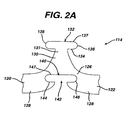
- the details of the bridges 114 are more fully illustrated in Figs. 2A, and 3A and described below.
- Each bridge comprises two ends wherein one end of each bridge 114 is attached to one loop 110 on one hoop 106(a) and the other end of each bridge 114 is attached to one loop 110 on an adjacent hoop 106(b).
- the bridges 114 connect adjacent hoops 106(a)-(d) together at bridge to loop connection regions 120,122 as shown in Fig. 2A.
- the above-described geometry better distributes strain throughout the stent 100, prevents metal to metal contact where the stent 100 is bent, and minimizes the opening between the features of the stent 100; namely, struts 108, loops 110 and bridges 114.
- the number of and nature of the design of the struts, loops and bridges are important design factors when determining the working properties and fatigue life properties of the stent 100. It was previously thought that in order to improve the rigidity of the stent, struts should be large, and thus there should be fewer struts 108 per hoop 106(a)-(d).
- each hoop 106(a)-(d) has between twenty-four (24) to thirty-six (36) or more struts 108. It has been determined that a stent having a ratio of number of struts per hoop to strut length which is greater than four hundred has increased rigidity over prior art stents which typically have a ratio of under two hundred. The length of a strut is measured in its compressed state parallel to the longitudinal axis 103 of the stent 100 as illustrated in Fig. 1A.
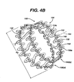
- Fig. 4A illustrates the stent 100 in its open or expanded state.
- the geometry of the stent 100 changes quite significantly as it is deployed from its unexpanded state (closed or locked configuration) to its expanded state (open or unlocked configuration).
- the strut angle and strain levels in the loops 110 and bridges 114 are affected.
- all of the stent features will strain in a predictable manner so that the stent 100 is reliable and uniform in strength.
- struts 108, loops 110 and bridges 114 it is preferable to minimize the maximum strain experienced by the struts 108, loops 110 and bridges 114 since the properties of nickel titanium alloys are more generally limited by strain rather than by stress.
- the embodiments illustrated in Figs. 1A to 5B has a design to help minimize forces such as strain.
- Fig. 1A illustrates the first embodiment of the stent 100 according to the present invention including a plurality of interlocking bridges 114 connecting adjacent hoops 106(a)-(d).
- stent 100 has bridges 114 wherein each bridge 114 includes a base 126.
- the base 126 has a pair of laterally extending arms 128 wherein each end of the lateral arms 128 are connected directly to a loop 110 at loop connection regions 120 and 122.
- one laterally extending arm connects to one of the adjacent hoops 106(a)-(d) at the loop connection region 120 of one loop 110 and the other lateral extending arm 128 of the bridge 114 is connected to an adjacent loop 110 at the loop connection region 122.
- the bridge 114 alternatively connects adjacent hoops 106(a)-(d).
- the bridge 114 further includes an extension 130 extending in a superior direction from the base 126.
- the extension 130 includes a neck 131 at the superior end of the extension 130.
- a projection 132 is fixed to the superior end of the neck 131 of the extension 130.
- the projection 132 can comprise any desired configuration, one preferred configuration for the projection 132 includes a pair of lateral lips 134 laterally extending from the neck 131 and a pair of lateral sidewalls 136 extending from the lateral lips 134 respectively.
- the lateral sidewalls 136 have a curved-shape.
- the projection 132 further includes an upper edge 137 extending between the lateral sidewalls 136.
- the bridge 114 further includes a projection holding section 140 inferior to the extension 130 at the base 126.
- the projection holding section 140 is defined by an opening 142 in the base 126.
- the projection holding section 140 further includes a pair of lateral ledges 144 extending from each side of the opening 142.
- the projection holding section 140 further includes a lateral depression 146 extending from each lateral ledge 144.
- Each lateral depression 146 also has a curved-shape for this embodiment.
- the projection holding section 140 includes an upper edge 147 extending between each lateral depression 146.
- the projection holding section 140 is shaped to fit and receive in a snap-fit or puzzle-lock manner the projection 132 of an adjacent bridge 114. Due to the unique configuration of the bridge 114, the projection 132 of a first bridge 114 is interlocked with the projection holding section 140 of a second bridge 114.
- the interlocking of bridges 114 is accomplished by insertion of the projection 132 of the first bridge 114 into the central opening 142 of the projection holding section 140 of the second bridge 114 such that the lateral lips 134 releasably engage the lateral ledges 144 of the projection holding section 140.
- the lateral sidewalls 136 of the projection 132 mates, in a releasable fashion, with the lateral depressions 146 of the projection holding section 140 of the second bridge 114.
- the upper edge 137 of the projection 132 of the first bridge 114 releasably mates with the upper edge 147 of the projection holding section 140 of the second bridge 114. Accordingly, this arrangement insures for an interlocking of the first and second bridges 114, e.g., adjacent bridges 114, in a puzzle-like manner.
- This arrangement of interlocking bridges 114 is clearly illustrated in Fig. 3A. When deployed to an open configuration, the stent 100 for the interlocking bridge embodiment described above expands to a width D 2 as shown in Fig 4A.
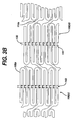
- FIG. 1B A second embodiment for the stent 100 is shown in Fig. 1B and includes a plurality of interlocking struts 108a.
- adjacent hoops 106(a) -(d) are connected to each other by nonlocking bridges 114a.
- a plurality of interlocking struts 108a are utilized in order to interlock by releasable engagement a first strut 108a with a second strut 108a as best shown in Fig. 3B.
- each interlocking strut 108a includes base 126 and laterally extending sidearms 128 as shown in Fig 2B.
- the strut 108a further includes extension 130 extending in a superior direction from the base 126.
- Projection 132 is fixed to the superior end of the extension 130.
- the projection 132 can comprise any desired configuration, one preferred configuration for the projection 132 includes a pair of lateral lips 134 laterally extending from the extension 130 and a pair of lateral sidewalls 136 extending from the lateral lips 134 respectively.
- the lateral sidewalls 136 have a curved-shape.
- the projection 132 further includes upper edge 137 extending between the sidewalls 136.
- the strut 108a (of the interlocking strut embodiment) further includes projection holding section 140 inferior to the extension 130 at the base 126.
- the projection holding section 140 is defined by opening 142 in the base 126.
- the projection holding section 140 further includes a pair of lateral ledges 144 extending from each side of the opening 142.
- the projection holding section 140 further includes lateral depression 146 extending from each lateral ledge 144.
- Each lateral depression 146 also has a curved-shape for this embodiment.
- the projection holding section 140 includes upper edge 147 extending between each lateral depression 146.
- the projection holding section 140 is shaped to fit and receive in a snap-fit or puzzle-lock manner the projection 132 of an adjacent strut 108a. Due to the unique configuration of the strut 108a, the projection 132 of a first strut 108a is interlocked with the projection holding section 140 of a second strut 108a.
- the interlocking of struts 108a is accomplished by insertion of the projection 132 of the first strut 108a into the central opening 142 of the projection holding section 140 of the second strut 108a such that the lateral lips 134 releasably engage the lateral ledges 144 of the projection holding section 140.
- the lateral sidewalls 136 of the projection 132 mates, in a releasable fashion, with the lateral depressions 146 of the projection holding section 140 of the second strut 108a.
- the upper edge 137 of the projection 132 of the first strut 108a releasably mates with the upper edge 147 of the projection holding section 140 of the second strut 108a. Accordingly, this arrangement insures for an interlocking of the first and second struts 108a, e.g., adjacent struts 108a, in a puzzle-like manner.
- This arrangement of interlocking struts 108a is clearly illustrated in Fig. 3B.
- the first strut 108a releasably engages with or interlocks with the second strut 108a in a puzzle-lock manner.
- the stent 100 having the interlocking struts 108a (the interlocking strut embodiment) is deployed or expanded to an open configuration having a width D 2 .
- the stent 100 according to the present invention for both the interlocking bridge 114 embodiment and the interlocking strut 108a embodiment is directed toward both deployment or expansion through an expandable member such as a balloon (to be described in greater detail below) and a self-expanding stent, i.e., a stent that is crush recoverable.
- an expandable member such as a balloon (to be described in greater detail below) and a self-expanding stent, i.e., a stent that is crush recoverable.
- the present invention also includes an apparatus and method for stenting a vessel utilizing the stent 100 (both the interlocking bridge 114 embodiment and the interlocking strut 108a embodiment).
- the stenting apparatus according to the present invention is generally designated 200 as best shown in Figs. 5A and 5B.
- Fig. 5A illustrates the apparatus 200 (as a catheter) which includes the stent 100 (the interlock bridge 114 embodiment)
- Fig. 5B illustrates the apparatus 200 including the second embodiment for the stent 100 (the interlocking strut 108a embodiment).
- the catheter 200 has a distal end 210 culminating in a distal tip 215.
- the catheter 200 includes an inner sleeve 220 extending to the distal tip 215.
- An expandable member 230 such as an inflatable balloon, is fixed to the inner sleeve 220 at the distal end 210 of the catheter 200.
- the expandable member 230 is expanded, such as through inflation with a hydraulic or pneumatic fluid, and is expandable from a collapsed or closed configuration to an open or expanded configuration.
- the stent 100 (both embodiments of Figs. 1A and 1B) according to the present invention are secured to the distal end of the catheter 200 by closing the stent 100 over the expandable member 230 and the inner sleeve 220 as best illustrated in Figs. 5A and 5B.
- the stent 100 is secured to the catheter 200 by closing the stent 100 respectively by moving the stent 100 and to its locked configuration.
- the locked configuration for the stent 100 includes interlocking the bridges 114 (for the interlocking bridge embodiment Fig. 5A) and for interlocking the struts 108a (for the interlocking strut embodiment Fig. 5B) in the respective manner described above.
- the bridges 114 are moved and interlocked (as shown in Fig. 3A) such that the stent 100 is locked and in its closed configuration over the expandable member 230.
- the struts 108a are moved and interlocked (as shown in Fig. 3B) such that the stent 100 is locked and in its closed configuration over the expandable member 230.
- the stent 100 is thereby secured to the catheter 200 until deployment is desired.
- An outer sheath 240 which is made of a polymer material such as polyethylene, is used as a cover for the catheter distal end 210 and serves as an additional form of protection for securing of the stent 100 (both embodiments) to the catheter distal end 210.
- the cover 240 is movably positioned or movably disposed from the catheter distal end 210 in order to provide both the protection as described above as well as the unimpeded deployment of the stent 100 upon positioning of the stent 100 at its desired location.
- the method of utilizing the catheter 200 includes first identifying a location in a patient's body for deployment of the stent 100. Upon identifying the desired deployment location, the catheter 200 is inserted within a vessel in the patient's body. The catheter 200 is used to traverse the vessel until reaching the desired location wherein the distal end 210 of the catheter 200 is positioned at the desired location within the vessel. At this point, the stent 100 is deployed to its open configuration by expanding the expandable member 230 such as by inflation. If the cover 240 is utilized to further protect and secure the stent 100 to the catheter distal end 210, the cover 240 is removed from the distal end 210 prior to expansion of the expandable member 230.
- the expandable member 230 Upon expanding the stent 100 to its open configuration, the expandable member 230 is then collapsed, for instance through deflation of the expandable member, whereby the catheter 200 is removed from the deployment site of the vessel and patient's body altogether.
Abstract
Description
- The present invention relates, in general, to intraluminal medical devices, and, more particularly, to a new and useful stent, and stent delivery apparatus.
- A stent is commonly used as a tubular structure left inside the lumen of a duct to relieve an obstruction. Commonly, stents are inserted into the lumen in a non-expanded form and are then expanded autonomously (or with the aid of a second device) in situ. When used in coronary artery procedures for relieving stenosis, stents are placed percutaneously through the femoral artery. In this type of procedure, stents are delivered on a catheter and are either self-expanding or, in the majority of cases, expanded by a balloon. Self-expanding stents do not need a balloon to be deployed. Rather the stents are constructed using metals with spring-like or superelastic properties (especially nickel titanium based alloys), which inherently exhibit constant radial support. Self-expanding stents are also often used in vessels close to the skin (i.e., carotid arteries) or vessels that can experience a lot of movement (i.e., popliteal artery). Due to a natural elastic recoil, self-expanding stents withstand pressure or shifting and maintain their shape.
- As mentioned above, the typical method of expansion for balloon expanded stents occurs through the use of a catheter mounted angioplasty balloon, which is inflated within the stenosed vessel or body passageway, in order to shear and disrupt the obstructions associated with the wall components of the vessel and to obtain an enlarged lumen.
- Balloon-expandable stents involve crimping the device onto an angioplasty balloon. The stent takes shape as the balloon is inflated and remains in place when the balloon and delivery system are deflated and removed.
- In addition, balloon-expandable stents are available either pre-mounted or unmounted. A pre-mounted system has the stent already crimped on a balloon, while an unmounted system gives the physician the option as to what combination of devices (catheters and stents) to use. Accordingly, for these types of procedures, the stent is first introduced into the blood vessel on a balloon catheter. Then, the balloon is inflated causing the stent to expand and press against the vessel wall. After expanding the stent, the balloon is deflated and withdrawn from the vessel together with the catheter. Once the balloon is withdrawn, the stent stays in place permanently, holding the vessel open and improving the flow of blood.
- In the absence of a stent, restenosis may occur as a result of elastic recoil of the stenotic lesion. Although a number of stent designs have been reported, these designs have suffered from a number of limitations. Some of these limitations include premature deployment of the stent due to circumstances such as over-manipulation when traversing tortuous vessels or the inability to maintain the stent secured to the balloon due to migration, slippage, etc.
- Accordingly, to date, there have not been any stent designs, that specifically address these drawbacks in an efficient and cost effective manner.
- DE-A-19728337 discusses a stent which can be locked in an expanded configuration.
- According to the present invention there is provided an apparatus for stenting a vessel as defined in appended claims 1 and 2.
- The present invention relates to an apparatus and method for stenting a vessel in conjunction with a particular new and useful stent having a lattice of interconnecting elements defining a substantially cylindrical configuration. The lattice has a first open end and a second open end wherein the lattice is movable between a locked configuration and an open configuration.
- One embodiment of the stent includes a plurality of bridges connecting the interconnecting elements wherein each bridge interlocks with an adjacent bridge in the locked configuration and wherein each bridge separates from the adjacent bridge in the open configuration.
- In another embodiment, the interlocking elements include a plurality of struts wherein each strut interlocks with an adjacent strut in the locked configuration and each strut separates from the adjacent strut in the open configuration.
- For the interlocking bridge embodiment, each bridge has a projection and a base wherein the base has a projection holding section for receiving the projection from an adjacent bridge. Likewise, for the interlocking strut embodiment, each strut has a projection and a base wherein the base has a projection holding section for receiving the projection from an adjacent strut. Accordingly, for both of the stent embodiments identified above, several features are in common. For instance, the interlocking elements comprise a plurality of adjacent sections. Additionally, the adjacent sections comprise adjacent hoops wherein each hoop comprises a plurality of loops. Each loop comprises at least one strut.
- For both the interlocking bridge embodiment and the interlocking strut embodiment, lateral arms extend from the base. Moreover, the projection holding section of the base has an opening therein for receiving the projection. An extension is connected between the base and the projection, and, for the interlocking bridge embodiment, the extension includes a neck wherein the projection is located at a superior position on the neck.
- The projection also includes at least one lateral lip and the projection holding section includes at least one lateral ledge for releasably engaging the at least one lateral lip of the projection. The projection also includes at least one sidewall adjacent to the at least one lateral lip. Additionally, the projection holding section includes at least one lateral depression adjacent to the at least one lateral ledge for releasably engaging the at least one sidewall of the projection.
- Although these features are intended to encompass any suitable configuration, in a preferred embodiment, the at least one sidewall is curved and the at least one depression is curved wherein these elements are aligned, snapped-fit or interlock in a puzzle-lock manner. Moreover, the lateral arms of the base connect directly to the interconnecting elements of the lattice.
- The stent of the present invention is directed toward both a balloon actuated stent and a self-expanding stent. The stent is made of any suitable material. In one embodiment, the stent is made of an alloy such as stainless steel. In another preferred embodiment, the stent is made of a nickel titanium based alloy. Moreover, this material or any other super-elastic alloy is suitable for the stent according to the present invention. In these self-expanding stent embodiments, the stent is a crush recoverable stent.
- The present invention is also directed toward an apparatus and method for stenting a vessel utilizing the stent embodiments described above, e.g., a stent having a lattice of interconnecting elements and including interlocking features such as a plurality of interlocking bridges in one embodiment or a plurality of interlocking struts in another embodiment.
- The apparatus further includes a catheter having an inner sleeve and an expandable member on the inner sleeve wherein the expandable member is movable between a collapsed state and an expanded state. One of the stent embodiments described above is secured to the catheter over the expandable member when the expandable member is in the collapsed state and the stent is in the locked configuration. The stent is separated or deployed from the catheter when the expandable member is in the expanded state and the stent is in the open configuration. The apparatus further includes a cover movably disposed over the stent. The cover is an outer sheath made of a polymer material. Additionally, the expandable member is an inflatable balloon.
- The apparatus according to the present invention, according to either embodiment, e.g., the interlocking bridge embodiment or the interlocking strut embodiment, is used in a method in which it is inserted within a vessel. The distal end of the apparatus is positioned at a desired location within the vessel and the stent is deployed to the open configuration with the expandable member.
- The method includes providing the cover movably disposed over the stent for preventing the stent from moving to the open configuration until desired. The method further includes deploying the stent to the open configuration by inflation of the expandable member.
- Additionally, the method includes securing the stent to the catheter by interlocking the bridges (for the interlocking bridge embodiment) or by interlocking the struts (for the interlocking strut embodiment) prior to performing certain steps according to the present invention. Lastly, the method according to the present invention also comprises removing the catheter from the patient after the deployment of the stent.
- Accordingly, the invention provides a method for stenting a vessel comprising the steps of:
- (a) providing an apparatus comprising:
- (i) a stent having a lattice of interconnecting elements defining a substantially cylindrical configuration having a first open end and a second open end, the lattice being movable between a closed configuration and an open configuration, and a plurality of bridges connecting the interconnecting elements, each bridge interlocking with an adjacent bridge in the locked configuration and each bridge separating from the adjacent bridge in the open configuration;
- (ii) a catheter having an inner sleeve and an expandable member on the inner sleeve, the expandable member being movable between a collapsed state and an expanded state, the stent being secured to the catheter over the expandable member when the expandable member is in the collapsed state and the stent is in the locked configuration and the stent being separated from the catheter when the expandable member is in the expanded state and the stent is in the open configuration;
- (b) inserting the apparatus within a vessel;
- (c) positioning the distal end of the apparatus at a desired location within the vessel; and
- (d) deploying the stent to the open configuration with the expandable member.
-
- In another aspect, the invention provides a method for stenting a vessel comprising the steps of:
- (a) providing an apparatus comprising:
- (i) a stent having a lattice of interconnecting elements defining a substantially cylindrical configuration having a first open end and a second open end, the lattice being movable between a closed configuration and an open configuration, and a plurality of struts connecting the interconnecting elements, each strut interlocking with an adjacent strut in the locked configuration and each strut separating from the adjacent strut in the open configuration;
- (ii) a catheter having an inner sleeve and an expandable member on the inner sleeve, the expandable member being movable between a collapsed state and an expanded state, the stent being secured to the catheter over the expandable member when the expandable member is in the collapsed state and the stent is in the locked configuration and the stent being separated from the catheter when the expandable member is in the expanded state and the stent is in the open configuration.
- (b) inserting the apparatus within a vessel;
- (c) positioning the distal end of the apparatus at a desired location within the vessel; and
- (d) deploying the stent to the open configuration with the expandable member.
-
- Preferably, the catheter includes a cover movably disposed over the stent wherein the cover prevents the stent from moving to the open configuration during steps (a)-(c). Preferably, the method includes the step of deploying the stent to the open configuration by inflation of the expandable member. Preferably, the method includes the step of securing the stent to the catheter by interlocking the bridges prior to performing steps (b)-(d), and preferably also the step of removing the catheter after performing step (d).
- Embodiments of the present invention will now be described by way of example with reference to the accompanying drawings, in which:
- Fig 1A is a perspective view of a first embodiment of a stent in a closed configuration in accordance with the present invention;
- Fig 1B is a perspective view of a second embodiment of a stent in a closed configuration in accordance with the present invention;
- Fig 2A is a partial side plan view of an interlocking bridge for the stent of Fig 1A;
- Fig 2B is a partial side plan view of an interlocking strut for the stent of Fig 1B;
- Fig 3A is a partial side view of the lattice of the stent of Fig 1A;
- Fig 3B is a partial side view of the lattice of the stent of Fig 1B;
- Fig 4A is a partial perspective view of the stent of Fig 1A in an open configuration;
- Fig 4B is a partial perspective view of the stent of Fig 1B in an open configuration;
- Fig 5A is a partial perspective view of a distal end of an apparatus according to the present invention utilizing the stent of Fig 1A; and
- Fig 5B is a partial perspective view of a distal end of an apparatus according to the present invention utilizing the stent of Fig 1B.
-
- Referring to the drawings, Figs. 1A, 1B, 4A and 4B show a
stent 100 that is an expandable prosthesis for a body passageway. It should be understood that the terms "stent" and "prosthesis" are interchangeably used to some extent in describing the present invention, insofar as the method, apparatus, and structures of the present invention may be utilized not only in connection with an expandable intraluminal vascular graft for expanding partially occluded segments of a blood vessel, duct or body passageways, such as within an organ, but may so be utilized for many other purposes as an expandable prosthesis for many other types of body passageways. For example, expandable prostheses may also be used for such purposes as: (1) supportive graft placement within blocked arteries opened by transluminal recanalization, but which are likely to collapse in the absence of internal support; (2) similar use following catheter passage through mediastinal and other veins occluded by inoperable cancers; (3) reinforcement of catheter created intrahepatic communications between portal and hepatic veins in patients suffering from portal hypertension; (4) supportive graft placement of narrowing of the esophagus, the intestine, the ureters, the uretha, etc.; (5) intraluminally bypassing a defect such as an aneurysm or blockage within a vessel or organ; and (6) supportive graft reinforcement of reopened and previously obstructed bile ducts. Accordingly, use of the term "prosthesis" encompasses the foregoing usages within various types of body passageways, and the use of the term "intraluminal graft" encompasses use for expanding the lumen of a body passageway. Further in this regard, the term "body passageway" encompasses any lumen or duct within the human body, such as those previously described, as well as any vein, artery, or blood vessel within the human vascular system. - The
stent 100 is an expandable lattice structure made of any suitable material which is compatible with the human body and the bodily fluids (not shown) with which thestent 100 may come into contact. The lattice structure is an arrangement of interconnecting elements made of a material which has the requisite strength and elasticity characteristics to permit the tubular shapedstent 100 to be expanded from the closed configuration shown in Figs. 1A and 1B to the expanded configuration shown in Figs. 4A and 4B and further to permit thestent 100 to retain its expanded configuration at the enlarged diameter d1. Suitable materials for the fabrication of thestent 100 include silver, tantalum, stainless steel, gold, titanium or any suitable plastic material having the requisite characteristics previously described. In one embodiment, the stent is fabricated from 316L stainless steel alloy - In a preferred embodiment, the
stent 100 comprises a superelastic nickel titanium based alloy. More preferably, thestent 100 is formed from an alloy comprising from about 50.5 to 60.0% Ni by atomic weight and the remainder Ti. Even more preferably, thestent 100 is formed from an alloy comprising about 55% Ni and about 45% Ti. Thestent 100 is preferably designed such that it is superelastic at body temperature, and preferably has an Af temperature in the range from about 24°C to about 37°C. The superelastic design of thestent 100 makes it crush recoverable and thus suitable as a stent or frame for any number of vascular devices for different applications. - The
stent 100 comprises a tubular configuration formed by a lattice of interconnecting elements defining a substantially cylindrical configuration and having front and back open ends 102, 104 and defining alongitudinal axis 103 extending between them. In its closed configuration, thestent 100 has a first diameter (d1) for insertion into a patient and navigation through the vessels and, in its open configuration, a second diameter (d2), as shown in Figs. 4A and 4B, for deployment into the target area of a vessel with the second diameter being greater than the first diameter. Thestent 100 comprises a plurality of adjacent hoops 106(a)-(d) extending between the front and back ends 102, 104. The hoops 106(a)-(d) include a plurality of longitudinally arrangedstruts 108 and a plurality ofloops 110 connectingadjacent struts 108.Adjacent struts 108 are connected at opposite ends so as to form a substantially S or Z shape pattern. The plurality ofloops 110 have a substantially semi-circular configuration and are substantially symmetric about their centres. - The
stent 100 further comprises a plurality ofbridges 114, which connect adjacent hoops 106(a)-(d). The details of thebridges 114 are more fully illustrated in Figs. 2A, and 3A and described below. Each bridge comprises two ends wherein one end of eachbridge 114 is attached to oneloop 110 on one hoop 106(a) and the other end of eachbridge 114 is attached to oneloop 110 on an adjacent hoop 106(b). Thebridges 114 connect adjacent hoops 106(a)-(d) together at bridge to loop connection regions 120,122 as shown in Fig. 2A. - The above-described geometry better distributes strain throughout the
stent 100, prevents metal to metal contact where thestent 100 is bent, and minimizes the opening between the features of thestent 100; namely, struts 108,loops 110 and bridges 114. The number of and nature of the design of the struts, loops and bridges are important design factors when determining the working properties and fatigue life properties of thestent 100. It was previously thought that in order to improve the rigidity of the stent, struts should be large, and thus there should befewer struts 108 per hoop 106(a)-(d). However, it is now known thatstents 100 havingsmaller struts 108 andmore struts 108 per hoop 106(a)-(d) improve the construction of thestent 100 and provide greater rigidity. Preferably, each hoop 106(a)-(d) has between twenty-four (24) to thirty-six (36) or more struts 108. It has been determined that a stent having a ratio of number of struts per hoop to strut length which is greater than four hundred has increased rigidity over prior art stents which typically have a ratio of under two hundred. The length of a strut is measured in its compressed state parallel to thelongitudinal axis 103 of thestent 100 as illustrated in Fig. 1A. - Fig. 4A illustrates the
stent 100 in its open or expanded state. As may be seen from a comparison between thestent 100 configuration illustrated in Fig. 1A and thestent 100 configuration illustrated in Fig. 4A, the geometry of thestent 100 changes quite significantly as it is deployed from its unexpanded state (closed or locked configuration) to its expanded state (open or unlocked configuration). As thestent 100 undergoes diametric change, the strut angle and strain levels in theloops 110 andbridges 114 are affected. Preferably, all of the stent features will strain in a predictable manner so that thestent 100 is reliable and uniform in strength. In addition, it is preferable to minimize the maximum strain experienced by thestruts 108,loops 110 andbridges 114 since the properties of nickel titanium alloys are more generally limited by strain rather than by stress. The embodiments illustrated in Figs. 1A to 5B has a design to help minimize forces such as strain. - Fig. 1A illustrates the first embodiment of the
stent 100 according to the present invention including a plurality of interlockingbridges 114 connecting adjacent hoops 106(a)-(d). In this embodiment, as best illustrated in Fig. 2A,stent 100 hasbridges 114 wherein eachbridge 114 includes abase 126. Thebase 126 has a pair of laterally extendingarms 128 wherein each end of thelateral arms 128 are connected directly to aloop 110 atloop connection regions loop connection region 120 of oneloop 110 and the otherlateral extending arm 128 of thebridge 114 is connected to anadjacent loop 110 at theloop connection region 122. Thus, thebridge 114 alternatively connects adjacent hoops 106(a)-(d). - The
bridge 114 further includes anextension 130 extending in a superior direction from thebase 126. Theextension 130 includes aneck 131 at the superior end of theextension 130. Aprojection 132 is fixed to the superior end of theneck 131 of theextension 130. Although theprojection 132 can comprise any desired configuration, one preferred configuration for theprojection 132 includes a pair oflateral lips 134 laterally extending from theneck 131 and a pair oflateral sidewalls 136 extending from thelateral lips 134 respectively. In this embodiment, thelateral sidewalls 136 have a curved-shape. Additionally, theprojection 132 further includes anupper edge 137 extending between thelateral sidewalls 136. - The
bridge 114 further includes aprojection holding section 140 inferior to theextension 130 at thebase 126. Theprojection holding section 140 is defined by anopening 142 in thebase 126. Theprojection holding section 140 further includes a pair oflateral ledges 144 extending from each side of theopening 142. Theprojection holding section 140 further includes alateral depression 146 extending from eachlateral ledge 144. Eachlateral depression 146 also has a curved-shape for this embodiment. Additionally, theprojection holding section 140 includes anupper edge 147 extending between eachlateral depression 146. - The
projection holding section 140 is shaped to fit and receive in a snap-fit or puzzle-lock manner theprojection 132 of anadjacent bridge 114. Due to the unique configuration of thebridge 114, theprojection 132 of afirst bridge 114 is interlocked with theprojection holding section 140 of asecond bridge 114. The interlocking ofbridges 114, which can be adjacent bridges, is accomplished by insertion of theprojection 132 of thefirst bridge 114 into thecentral opening 142 of theprojection holding section 140 of thesecond bridge 114 such that thelateral lips 134 releasably engage thelateral ledges 144 of theprojection holding section 140. Moreover, thelateral sidewalls 136 of theprojection 132 mates, in a releasable fashion, with thelateral depressions 146 of theprojection holding section 140 of thesecond bridge 114. Furthermore, theupper edge 137 of theprojection 132 of thefirst bridge 114 releasably mates with theupper edge 147 of theprojection holding section 140 of thesecond bridge 114. Accordingly, this arrangement insures for an interlocking of the first andsecond bridges 114, e.g.,adjacent bridges 114, in a puzzle-like manner. This arrangement of interlockingbridges 114 is clearly illustrated in Fig. 3A. When deployed to an open configuration, thestent 100 for the interlocking bridge embodiment described above expands to a width D2 as shown in Fig 4A. - A second embodiment for the
stent 100 is shown in Fig. 1B and includes a plurality of interlocking struts 108a. In this embodiment, adjacent hoops 106(a) -(d) are connected to each other bynonlocking bridges 114a. - For the embodiment of Fig. 1B (the interlocking strut embodiment), a plurality of interlocking
struts 108a are utilized in order to interlock by releasable engagement afirst strut 108a with asecond strut 108a as best shown in Fig. 3B. - For purposes of this disclosure, the same reference numerals are used to designate like or similar features for both the interlocking
bridge 114 embodiment (Fig. 1A) and theinterlocking strut 108a embodiment (Fig. 1B). Accordingly, each interlockingstrut 108a includesbase 126 and laterally extendingsidearms 128 as shown in Fig 2B. - As illustrated in Fig. 2B, the
strut 108a further includesextension 130 extending in a superior direction from thebase 126.Projection 132 is fixed to the superior end of theextension 130. Although theprojection 132 can comprise any desired configuration, one preferred configuration for theprojection 132 includes a pair oflateral lips 134 laterally extending from theextension 130 and a pair oflateral sidewalls 136 extending from thelateral lips 134 respectively. In this embodiment, thelateral sidewalls 136 have a curved-shape. Additionally, theprojection 132 further includesupper edge 137 extending between thesidewalls 136. - The
strut 108a (of the interlocking strut embodiment) further includesprojection holding section 140 inferior to theextension 130 at thebase 126. Theprojection holding section 140 is defined by opening 142 in thebase 126. Theprojection holding section 140 further includes a pair oflateral ledges 144 extending from each side of theopening 142. Theprojection holding section 140 further includeslateral depression 146 extending from eachlateral ledge 144. Eachlateral depression 146 also has a curved-shape for this embodiment. Additionally, theprojection holding section 140 includesupper edge 147 extending between eachlateral depression 146. - As best illustrated in Fig. 3B, the
projection holding section 140 is shaped to fit and receive in a snap-fit or puzzle-lock manner theprojection 132 of anadjacent strut 108a. Due to the unique configuration of thestrut 108a, theprojection 132 of afirst strut 108a is interlocked with theprojection holding section 140 of asecond strut 108a. The interlocking of struts 108a, which can be adjacent struts, is accomplished by insertion of theprojection 132 of thefirst strut 108a into thecentral opening 142 of theprojection holding section 140 of thesecond strut 108a such that thelateral lips 134 releasably engage thelateral ledges 144 of theprojection holding section 140. Moreover, thelateral sidewalls 136 of theprojection 132 mates, in a releasable fashion, with thelateral depressions 146 of theprojection holding section 140 of thesecond strut 108a. Furthermore, theupper edge 137 of theprojection 132 of thefirst strut 108a releasably mates with theupper edge 147 of theprojection holding section 140 of thesecond strut 108a. Accordingly, this arrangement insures for an interlocking of the first andsecond struts 108a, e.g.,adjacent struts 108a, in a puzzle-like manner. This arrangement of interlockingstruts 108a is clearly illustrated in Fig. 3B. Thus, thefirst strut 108a releasably engages with or interlocks with thesecond strut 108a in a puzzle-lock manner. - As mentioned above with the interlocking bridge embodiment of Fig. 4A, as shown in Fig. 4B, the
stent 100 having the interlocking struts 108a (the interlocking strut embodiment) is deployed or expanded to an open configuration having a width D2. - The
stent 100 according to the present invention for both the interlockingbridge 114 embodiment and theinterlocking strut 108a embodiment is directed toward both deployment or expansion through an expandable member such as a balloon (to be described in greater detail below) and a self-expanding stent, i.e., a stent that is crush recoverable. - The present invention also includes an apparatus and method for stenting a vessel utilizing the stent 100 (both the interlocking
bridge 114 embodiment and theinterlocking strut 108a embodiment). The stenting apparatus according to the present invention is generally designated 200 as best shown in Figs. 5A and 5B. Fig. 5A illustrates the apparatus 200 (as a catheter) which includes the stent 100 (theinterlock bridge 114 embodiment) and Fig. 5B illustrates theapparatus 200 including the second embodiment for the stent 100 (the interlockingstrut 108a embodiment). As illustrated in Figs. 5A and 5B, thecatheter 200 has adistal end 210 culminating in adistal tip 215. Thecatheter 200 includes aninner sleeve 220 extending to thedistal tip 215. Anexpandable member 230, such as an inflatable balloon, is fixed to theinner sleeve 220 at thedistal end 210 of thecatheter 200. As is well understood in the field, theexpandable member 230 is expanded, such as through inflation with a hydraulic or pneumatic fluid, and is expandable from a collapsed or closed configuration to an open or expanded configuration. The stent 100 (both embodiments of Figs. 1A and 1B) according to the present invention are secured to the distal end of thecatheter 200 by closing thestent 100 over theexpandable member 230 and theinner sleeve 220 as best illustrated in Figs. 5A and 5B. Thestent 100 is secured to thecatheter 200 by closing thestent 100 respectively by moving thestent 100 and to its locked configuration. As described above, the locked configuration for thestent 100 includes interlocking the bridges 114 (for the interlocking bridge embodiment Fig. 5A) and for interlocking the struts 108a (for the interlocking strut embodiment Fig. 5B) in the respective manner described above. - In securing the
stent 100 to the catheterdistal end 210 for the interlocking bridge embodiment of Fig. 5A, thebridges 114 are moved and interlocked (as shown in Fig. 3A) such that thestent 100 is locked and in its closed configuration over theexpandable member 230. - In securing the
stent 100 to the catheterdistal end 210 for the interlocking strut embodiment of Fig. 5B, thestruts 108a are moved and interlocked (as shown in Fig. 3B) such that thestent 100 is locked and in its closed configuration over theexpandable member 230. - For both embodiments mentioned above, the
stent 100 is thereby secured to thecatheter 200 until deployment is desired. Anouter sheath 240, which is made of a polymer material such as polyethylene, is used as a cover for the catheterdistal end 210 and serves as an additional form of protection for securing of the stent 100 (both embodiments) to the catheterdistal end 210. Thecover 240 is movably positioned or movably disposed from the catheterdistal end 210 in order to provide both the protection as described above as well as the unimpeded deployment of thestent 100 upon positioning of thestent 100 at its desired location. - The method of utilizing the
catheter 200 according to the present invention includes first identifying a location in a patient's body for deployment of thestent 100. Upon identifying the desired deployment location, thecatheter 200 is inserted within a vessel in the patient's body. Thecatheter 200 is used to traverse the vessel until reaching the desired location wherein thedistal end 210 of thecatheter 200 is positioned at the desired location within the vessel. At this point, thestent 100 is deployed to its open configuration by expanding theexpandable member 230 such as by inflation. If thecover 240 is utilized to further protect and secure thestent 100 to the catheterdistal end 210, thecover 240 is removed from thedistal end 210 prior to expansion of theexpandable member 230. - Upon expanding the
stent 100 to its open configuration, theexpandable member 230 is then collapsed, for instance through deflation of the expandable member, whereby thecatheter 200 is removed from the deployment site of the vessel and patient's body altogether.
Claims (28)
- An apparatus for stenting a vessel comprising:wherein the stent (100) is secured to the catheter (200) over the expandable member (230) when the expandable member (230) is in the collapsed state and the stent (100) is in the locked configuration; and wherein the stent (100) is separated from the catheter (200) when the expandable member (230) is in the expanded state and the stent (100) is in the open configuration.(i) a stent (100) having a lattice of interconnecting elements defining a substantially cylindrical configuration having a first open end (102) and a second open end (104), wherein the lattice is movable between a locked configuration and an open configuration, and a plurality of bridges (114) connecting the interconnecting elements,
wherein each bridge (114) interlocks with an adjacent bridge (114) in the locked configuration and each bridge (114) separates from the adjacent bridge (114) in the open configuration;(ii) a catheter (200) having an inner sleeve (220) and an expandable member (230) on the inner sleeve (200), wherein the expandable member is movable between a collapsed state and an expanded state, - An apparatus for stenting a vessel comprising:wherein the stent (100) is secured to the catheter (200) over the expandable member (230) when the expandable member (230) is in the collapsed state and the stent (100) is in the locked configuration; and wherein the stent (100) is separated from the catheter (200) when the expandable member (230) is in the expanded state and the stent (100) is in the open configuration.(i) a stent (100) having a lattice of interconnecting elements defining a substantially cylindrical configuration having a first open end (102) and a second open end (104), wherein the lattice is movable between a locked configuration and an open configuration, wherein the interconnecting elements include a plurality of struts, (108a) and each strut (108a) interlocks with an adjacent strut (108a) in the locked configuration and each strut (108a) separates from the adjacent strut in the open configuration;(ii) a catheter (200) having an inner sleeve (220) and an expandable member (230) on the inner sleeve (220), wherein the expandable member (230) is movable between a collapsed state and an expanded state,
- Apparatus as claimed in claim 1 or 2, wherein the catheter includes a cover (240) movably disposed over the stent (100).
- Apparatus as claimed in claim 1 or 2, wherein the expandable member (230) is an inflatable balloon.
- Apparatus as claimed in claim 4, wherein the cover (240) is an outer sheath.
- Apparatus as claimed in claim 5, wherein the sheath is made of a polymer.
- Apparatus as claimed in claim 1 or 2, wherein the stent (100) is made of an alloy.
- Apparatus as claimed in claim 7, wherein the stent (100) is made of stainless steel.
- Apparatus as claimed in claim 1 or 2, wherein the stent (100) is crush recoverable.
- Apparatus as claimed in claim 9, wherein the stent (100) comprises a nickel titanium based alloy.
- Apparatus as claimed in claim 7, wherein the stent (100) is made of a superelastic alloy.
- Apparatus as claimed in claim 11, wherein the stent (100) comprises a nickel titanium based alloy.
- Apparatus as claimed in claim 1 or 2, wherein each bridge (114) or stent (108a) has a projection (132) and a base (126), the base having a projection holding section (140) for receiving the projection (132) from the adjacent bridge (114) or strut (108a).
- Apparatus as claimed in claim 13, wherein the interconnecting elements comprise a plurality of adjacent sections.
- Apparatus as claimed in claim 14, wherein the adjacent sections comprise adjacent hoops.
- Apparatus as claimed in claim 15, wherein each hoop comprises a plurality of loops.
- Apparatus as claimed in claim 16, wherein each hoop comprises at least one strut.
- Apparatus as claimed in claim 14, wherein each bridge (114) or strut (108a) has lateral arms (128) extending from the base (126).
- Apparatus as claimed in claim 18, wherein the projection holding section (140) has an opening therein.
- Apparatus as claimed in claim 19, wherein an extension (130) is connected between the base (126) and the projection (132).
- Apparatus as claimed in claim 20 when appendant to claim 1, wherein the extension (130) includes a neck (131) and the projection (132) is located at a superior position on the neck (131).
- The apparatus according to Clam 21, wherein the projection (132) includes at least one lateral lip (134).
- Apparatus as claimed in claim 22, wherein the projection holding section (140) includes at least one lateral ledge (144) for releasable engaging the at least one lateral lip (134) of the projection (132).
- Apparatus as claimed in claim 23, wherein the projection (132) includes at least one sidewall adjacent the at least one lateral lip.
- Apparatus as claimed in claim 24, wherein the projection holding section (140) includes at least one lateral depression adjacent the at least one lateral ledge for releasably engaging the at least one sidewall of the projection.
- Apparatus as claimed in claim 25, wherein the at least one sidewall is curved.
- Apparatus as claimed in claim 26, wherein the at least one depression is curved.
- Apparatus as claimed in claim 27, wherein the lateral arms (128) connect the interconnecting elements.
Applications Claiming Priority (3)
| Application Number | Priority Date | Filing Date | Title |
|---|---|---|---|
| US877672 | 2001-06-08 | ||
| US09/877,672 US6599314B2 (en) | 2001-06-08 | 2001-06-08 | Apparatus and method for stenting a vessel using balloon-actuated stent with interlocking elements |
| US09/877,506 US6562067B2 (en) | 2001-06-08 | 2001-06-08 | Stent with interlocking elements |
Publications (3)
| Publication Number | Publication Date |
|---|---|
| EP1266638A2 EP1266638A2 (en) | 2002-12-18 |
| EP1266638A3 EP1266638A3 (en) | 2003-03-19 |
| EP1266638B1 true EP1266638B1 (en) | 2005-10-19 |
Family
ID=39267971
Family Applications (1)
| Application Number | Title | Priority Date | Filing Date |
|---|---|---|---|
| EP02253789A Expired - Lifetime EP1266638B1 (en) | 2001-06-08 | 2002-05-30 | Balloon-actuated stent with interlocking elements |
Country Status (11)
| Country | Link |
|---|---|
| US (2) | US6599314B2 (en) |
| EP (1) | EP1266638B1 (en) |
| JP (1) | JP4233810B2 (en) |
| KR (1) | KR100855889B1 (en) |
| AT (1) | ATE306874T1 (en) |
| AU (1) | AU782122C (en) |
| CA (1) | CA2389401C (en) |
| DE (1) | DE60206694T2 (en) |
| DK (1) | DK1266638T3 (en) |
| ES (1) | ES2250587T3 (en) |
| IL (1) | IL149646A0 (en) |
Cited By (22)
| Publication number | Priority date | Publication date | Assignee | Title |
|---|---|---|---|---|
| US7892273B2 (en) | 2001-12-03 | 2011-02-22 | Xtent, Inc. | Custom length stent apparatus |
| US7892274B2 (en) | 2001-12-03 | 2011-02-22 | Xtent, Inc. | Apparatus and methods for deployment of vascular prostheses |
| US7905913B2 (en) | 2001-12-03 | 2011-03-15 | Xtent, Inc. | Apparatus and methods for delivery of multiple distributed stents |
| US7918881B2 (en) | 2003-06-09 | 2011-04-05 | Xtent, Inc. | Stent deployment systems and methods |
| US7922755B2 (en) | 2001-12-03 | 2011-04-12 | Xtent, Inc. | Apparatus and methods for delivery of multiple distributed stents |
| US7938852B2 (en) | 2001-12-03 | 2011-05-10 | Xtent, Inc. | Apparatus and methods for delivery of braided prostheses |
| US8016870B2 (en) | 2001-12-03 | 2011-09-13 | Xtent, Inc. | Apparatus and methods for delivery of variable length stents |
| US8080048B2 (en) | 2001-12-03 | 2011-12-20 | Xtent, Inc. | Stent delivery for bifurcated vessels |
| US8177831B2 (en) | 2001-12-03 | 2012-05-15 | Xtent, Inc. | Stent delivery apparatus and method |
| US8257427B2 (en) | 2001-09-11 | 2012-09-04 | J.W. Medical Systems, Ltd. | Expandable stent |
| US8282680B2 (en) | 2003-01-17 | 2012-10-09 | J. W. Medical Systems Ltd. | Multiple independent nested stent structures and methods for their preparation and deployment |
| US8317859B2 (en) | 2004-06-28 | 2012-11-27 | J.W. Medical Systems Ltd. | Devices and methods for controlling expandable prostheses during deployment |
| US8460358B2 (en) | 2004-03-30 | 2013-06-11 | J.W. Medical Systems, Ltd. | Rapid exchange interventional devices and methods |
| US8486132B2 (en) | 2007-03-22 | 2013-07-16 | J.W. Medical Systems Ltd. | Devices and methods for controlling expandable prostheses during deployment |
| US8585747B2 (en) | 2003-12-23 | 2013-11-19 | J.W. Medical Systems Ltd. | Devices and methods for controlling and indicating the length of an interventional element |
| US8652198B2 (en) | 2006-03-20 | 2014-02-18 | J.W. Medical Systems Ltd. | Apparatus and methods for deployment of linked prosthetic segments |
| EP2799036A1 (en) | 2013-04-02 | 2014-11-05 | Biotronik AG | Intraluminal endoprosthesis and method for production thereof |
| US8980297B2 (en) | 2007-02-20 | 2015-03-17 | J.W. Medical Systems Ltd. | Thermo-mechanically controlled implants and methods of use |
| US8986362B2 (en) | 2004-06-28 | 2015-03-24 | J.W. Medical Systems Ltd. | Devices and methods for controlling expandable prostheses during deployment |
| US9101503B2 (en) | 2008-03-06 | 2015-08-11 | J.W. Medical Systems Ltd. | Apparatus having variable strut length and methods of use |
| US10219923B2 (en) | 2005-06-08 | 2019-03-05 | J.W. Medical Systems Ltd. | Apparatus and methods for deployment of multiple custom-length prostheses (III) |
| US10219927B2 (en) | 2008-09-25 | 2019-03-05 | Advanced Bifurcation Systems Inc. | System and methods for treating a bifurcation |
Families Citing this family (148)
| Publication number | Priority date | Publication date | Assignee | Title |
|---|---|---|---|---|
| JP4046760B2 (en) * | 1994-05-19 | 2008-02-13 | ボストン サイエンティフィック サイムド, インコーポレイテッド | Improved tissue support device |
| US5938697A (en) | 1998-03-04 | 1999-08-17 | Scimed Life Systems, Inc. | Stent having variable properties |
| US6241762B1 (en) | 1998-03-30 | 2001-06-05 | Conor Medsystems, Inc. | Expandable medical device with ductile hinges |
| US7208010B2 (en) | 2000-10-16 | 2007-04-24 | Conor Medsystems, Inc. | Expandable medical device for delivery of beneficial agent |
| EP1132058A1 (en) | 2000-03-06 | 2001-09-12 | Advanced Laser Applications Holding S.A. | Intravascular prothesis |
| EP1582180B1 (en) | 2000-10-16 | 2008-02-27 | Conor Medsystems, Inc. | Expandable medical device for delivery of beneficial agent |
| US6764507B2 (en) * | 2000-10-16 | 2004-07-20 | Conor Medsystems, Inc. | Expandable medical device with improved spatial distribution |
| EP1258230A3 (en) | 2001-03-29 | 2003-12-10 | CardioSafe Ltd | Balloon catheter device |
| US6800090B2 (en) * | 2001-05-14 | 2004-10-05 | Cardiac Dimensions, Inc. | Mitral valve therapy device, system and method |
| US7842083B2 (en) | 2001-08-20 | 2010-11-30 | Innovational Holdings, Llc. | Expandable medical device with improved spatial distribution |
| US7635387B2 (en) | 2001-11-01 | 2009-12-22 | Cardiac Dimensions, Inc. | Adjustable height focal tissue deflector |
| US6824562B2 (en) | 2002-05-08 | 2004-11-30 | Cardiac Dimensions, Inc. | Body lumen device anchor, device and assembly |
| US6949122B2 (en) * | 2001-11-01 | 2005-09-27 | Cardiac Dimensions, Inc. | Focused compression mitral valve device and method |
| US7182779B2 (en) | 2001-12-03 | 2007-02-27 | Xtent, Inc. | Apparatus and methods for positioning prostheses for deployment from a catheter |
| US6908478B2 (en) * | 2001-12-05 | 2005-06-21 | Cardiac Dimensions, Inc. | Anchor and pull mitral valve device and method |
| US7179282B2 (en) * | 2001-12-05 | 2007-02-20 | Cardiac Dimensions, Inc. | Device and method for modifying the shape of a body organ |
| US6976995B2 (en) | 2002-01-30 | 2005-12-20 | Cardiac Dimensions, Inc. | Fixed length anchor and pull mitral valve device and method |
| US6793673B2 (en) * | 2002-12-26 | 2004-09-21 | Cardiac Dimensions, Inc. | System and method to effect mitral valve annulus of a heart |
| US20050209690A1 (en) * | 2002-01-30 | 2005-09-22 | Mathis Mark L | Body lumen shaping device with cardiac leads |
| US20030163190A1 (en) * | 2002-02-25 | 2003-08-28 | Scimed Life Systems, Inc. | High temperature stent delivery system |
| CA2877641C (en) * | 2002-05-08 | 2017-01-17 | Cardiac Dimensions Pty. Ltd. | Device and method for modifying the shape of a body organ |
| US7704276B2 (en) * | 2002-11-15 | 2010-04-27 | Synecor, Llc | Endoprostheses and methods of manufacture |
| US7837729B2 (en) * | 2002-12-05 | 2010-11-23 | Cardiac Dimensions, Inc. | Percutaneous mitral valve annuloplasty delivery system |
| US7316708B2 (en) * | 2002-12-05 | 2008-01-08 | Cardiac Dimensions, Inc. | Medical device delivery system |
| US7314485B2 (en) * | 2003-02-03 | 2008-01-01 | Cardiac Dimensions, Inc. | Mitral valve device using conditioned shape memory alloy |
| US20040158321A1 (en) * | 2003-02-12 | 2004-08-12 | Cardiac Dimensions, Inc. | Method of implanting a mitral valve therapy device |
| US7918884B2 (en) * | 2003-02-25 | 2011-04-05 | Cordis Corporation | Stent for treatment of bifurcated lesions |
| US7942920B2 (en) * | 2003-02-25 | 2011-05-17 | Cordis Corporation | Stent with nested fingers for enhanced vessel coverage |
| US20040249442A1 (en) * | 2003-02-26 | 2004-12-09 | Fleming James A. | Locking stent having multiple locking points |
| US20040167610A1 (en) | 2003-02-26 | 2004-08-26 | Fleming James A. | Locking stent |
| US7214240B2 (en) * | 2003-03-20 | 2007-05-08 | Cordis Corporation | Split-bridge stent design |
| US20040220657A1 (en) * | 2003-05-02 | 2004-11-04 | Cardiac Dimensions, Inc., A Washington Corporation | Tissue shaping device with conformable anchors |
| US20040220654A1 (en) | 2003-05-02 | 2004-11-04 | Cardiac Dimensions, Inc. | Device and method for modifying the shape of a body organ |
| US7887582B2 (en) * | 2003-06-05 | 2011-02-15 | Cardiac Dimensions, Inc. | Device and method for modifying the shape of a body organ |
| AU2004263171B2 (en) * | 2003-08-07 | 2008-12-04 | Merit Medical Systems, Inc. | Therapeutic medical appliance, delivery and method of use |
| US7175654B2 (en) * | 2003-10-16 | 2007-02-13 | Cordis Corporation | Stent design having stent segments which uncouple upon deployment |
| US20050085897A1 (en) * | 2003-10-17 | 2005-04-21 | Craig Bonsignore | Stent design having independent stent segments which uncouple upon deployment |
| US8157855B2 (en) * | 2003-12-05 | 2012-04-17 | Boston Scientific Scimed, Inc. | Detachable segment stent |
| US7403966B2 (en) * | 2003-12-08 | 2008-07-22 | Freescale Semiconductor, Inc. | Hardware for performing an arithmetic function |
| US20050137450A1 (en) * | 2003-12-19 | 2005-06-23 | Cardiac Dimensions, Inc., A Washington Corporation | Tapered connector for tissue shaping device |
| US7837728B2 (en) * | 2003-12-19 | 2010-11-23 | Cardiac Dimensions, Inc. | Reduced length tissue shaping device |
| US20060271174A1 (en) * | 2003-12-19 | 2006-11-30 | Gregory Nieminen | Mitral Valve Annuloplasty Device with Wide Anchor |
| US7794496B2 (en) | 2003-12-19 | 2010-09-14 | Cardiac Dimensions, Inc. | Tissue shaping device with integral connector and crimp |
| US9526616B2 (en) * | 2003-12-19 | 2016-12-27 | Cardiac Dimensions Pty. Ltd. | Mitral valve annuloplasty device with twisted anchor |
| DE102004003093B4 (en) * | 2004-01-21 | 2009-01-29 | Admedes Schuessler Gmbh | Stent for insertion and expansion in a lumen |
| US7479158B2 (en) * | 2004-02-20 | 2009-01-20 | Boston Scientific Scimed, Inc. | Stent with nested flexible connectors for flexibility and crimpability |
| US8568469B1 (en) * | 2004-06-28 | 2013-10-29 | Advanced Cardiovascular Systems, Inc. | Stent locking element and a method of securing a stent on a delivery system |
| US9283099B2 (en) | 2004-08-25 | 2016-03-15 | Advanced Cardiovascular Systems, Inc. | Stent-catheter assembly with a releasable connection for stent retention |
| WO2006024491A1 (en) | 2004-08-30 | 2006-03-09 | Interstitial Therapeutics | Methods and compositions for the treatment of cell proliferation |
| US20060069424A1 (en) * | 2004-09-27 | 2006-03-30 | Xtent, Inc. | Self-constrained segmented stents and methods for their deployment |
| AU2006206254B2 (en) | 2005-01-20 | 2012-02-09 | Cardiac Dimensions Pty. Ltd. | Tissue shaping device |
| FR2881946B1 (en) * | 2005-02-17 | 2008-01-04 | Jacques Seguin | DEVICE FOR THE TREATMENT OF BODILY CONDUIT AT BIFURCATION LEVEL |
| US8002818B2 (en) * | 2005-02-25 | 2011-08-23 | Abbott Laboratories Vascular Enterprises Limited | Modular vascular prosthesis having axially variable properties and improved flexibility and methods of use |
| US8025694B2 (en) | 2005-02-25 | 2011-09-27 | Abbott Laboratories Vascular Enterprises Limited | Modular vascular prosthesis and methods of use |
| US20070213810A1 (en) * | 2005-03-14 | 2007-09-13 | Richard Newhauser | Segmented endoprosthesis |
| CN101484089B (en) | 2005-04-04 | 2015-11-25 | 可挠支架装置公司 | Flexible stent |
| US20060271158A1 (en) * | 2005-05-26 | 2006-11-30 | Boston Scientific Scimed, Inc. | Positional locking endoluminal device system |
| US7938851B2 (en) | 2005-06-08 | 2011-05-10 | Xtent, Inc. | Devices and methods for operating and controlling interventional apparatus |
| US9192494B2 (en) * | 2005-08-29 | 2015-11-24 | Advanced Cardiovascular Systems, Inc. | Locking polymer stents |
| US8043366B2 (en) | 2005-09-08 | 2011-10-25 | Boston Scientific Scimed, Inc. | Overlapping stent |
| US8956400B2 (en) * | 2005-10-14 | 2015-02-17 | Flexible Stenting Solutions, Inc. | Helical stent |
| US8652192B2 (en) * | 2006-03-31 | 2014-02-18 | St. Jude Medical, Cardiology Division, Inc. | Stent and system and method for deploying a stent |
| US7503932B2 (en) | 2006-04-11 | 2009-03-17 | Cardiac Dimensions, Inc. | Mitral valve annuloplasty device with vena cava anchor |
| AU2007258592B2 (en) | 2006-06-06 | 2012-10-25 | Cook Incorporated | Stent with a crush-resistant zone |
| US8613698B2 (en) | 2006-07-10 | 2013-12-24 | Mcneil-Ppc, Inc. | Resilient device |
| CN104257450B (en) * | 2006-07-10 | 2017-05-10 | 第一次质量卫生公司 | Resilient Device |
| US10004584B2 (en) | 2006-07-10 | 2018-06-26 | First Quality Hygienic, Inc. | Resilient intravaginal device |
| US10219884B2 (en) | 2006-07-10 | 2019-03-05 | First Quality Hygienic, Inc. | Resilient device |
| US8047980B2 (en) | 2006-07-10 | 2011-11-01 | Mcneil-Ppc, Inc. | Method of treating urinary incontinence |
| US11285005B2 (en) | 2006-07-17 | 2022-03-29 | Cardiac Dimensions Pty. Ltd. | Mitral valve annuloplasty device with twisted anchor |
| WO2008011612A2 (en) * | 2006-07-20 | 2008-01-24 | Orbusneich Medical, Inc. | Bioabsorbable polymeric medical device |
| US7833260B2 (en) * | 2006-07-20 | 2010-11-16 | Orbusneich Medical, Inc. | Bioabsorbable polymeric medical device |
| EP3009477B1 (en) | 2006-07-20 | 2024-01-24 | Orbusneich Medical Pte. Ltd | Bioabsorbable polymeric composition for a medical device |
| CN101631513B (en) * | 2006-10-20 | 2013-06-05 | 奥巴斯尼茨医学公司 | Bioabsorbable polymeric composition and medical device |
| US7959942B2 (en) * | 2006-10-20 | 2011-06-14 | Orbusneich Medical, Inc. | Bioabsorbable medical device with coating |
| US20080099170A1 (en) * | 2006-10-31 | 2008-05-01 | The Procter & Gamble Company | Process of making wet-microcontracted paper |
| FR2911063B1 (en) | 2007-01-09 | 2009-03-20 | Stentys S A S Soc Par Actions | RUPTIBLE BRIDGE STRUCTURE FOR STENT, AND STENT INCLUDING SUCH BRIDGE STRUCTURES. |
| DE102007015670A1 (en) * | 2007-03-31 | 2008-10-02 | Biotronik Vi Patent Ag | Stent with radially expandable body |
| US20100094405A1 (en) * | 2008-10-10 | 2010-04-15 | Orbusneich Medical, Inc. | Bioabsorbable Polymeric Medical Device |
| US20110130822A1 (en) * | 2007-07-20 | 2011-06-02 | Orbusneich Medical, Inc. | Bioabsorbable Polymeric Compositions and Medical Devices |
| US7988723B2 (en) | 2007-08-02 | 2011-08-02 | Flexible Stenting Solutions, Inc. | Flexible stent |
| US8226701B2 (en) | 2007-09-26 | 2012-07-24 | Trivascular, Inc. | Stent and delivery system for deployment thereof |
| US8066755B2 (en) | 2007-09-26 | 2011-11-29 | Trivascular, Inc. | System and method of pivoted stent deployment |
| US8663309B2 (en) | 2007-09-26 | 2014-03-04 | Trivascular, Inc. | Asymmetric stent apparatus and method |
| CN101917929A (en) | 2007-10-04 | 2010-12-15 | 特里瓦斯库拉尔公司 | Modular vascular graft for low profile percutaneous delivery |
| US8328861B2 (en) | 2007-11-16 | 2012-12-11 | Trivascular, Inc. | Delivery system and method for bifurcated graft |
| US8083789B2 (en) | 2007-11-16 | 2011-12-27 | Trivascular, Inc. | Securement assembly and method for expandable endovascular device |
| WO2009069113A1 (en) * | 2007-11-28 | 2009-06-04 | The Provost, Fellows And Scholars Of The College Of The Holy And Undivided Trinity Of Queen Elizabeth Near Dublin | A luminal prosthesis |
| US20090234429A1 (en) * | 2008-02-07 | 2009-09-17 | Lilip Lau | Self-restraining endoluminal prosthesis |
| US9005274B2 (en) * | 2008-08-04 | 2015-04-14 | Stentys Sas | Method for treating a body lumen |
| US8006594B2 (en) | 2008-08-11 | 2011-08-30 | Cardiac Dimensions, Inc. | Catheter cutting tool |
| US20100057187A1 (en) * | 2008-08-26 | 2010-03-04 | Caldarise Salvatore G | Intravascular stent having imrproved design for loading and deploying |
| US8128678B2 (en) * | 2008-09-02 | 2012-03-06 | Cook Medical Technologies Llc | Stent having less invasive ends and improved radial force |
| US9060892B2 (en) * | 2008-09-15 | 2015-06-23 | Abbott Laboratories Vascular Enterprises Limited | Stent with independent stent rings and transitional attachments |
| US11298252B2 (en) | 2008-09-25 | 2022-04-12 | Advanced Bifurcation Systems Inc. | Stent alignment during treatment of a bifurcation |
| US8821562B2 (en) | 2008-09-25 | 2014-09-02 | Advanced Bifurcation Systems, Inc. | Partially crimped stent |
| US8828071B2 (en) | 2008-09-25 | 2014-09-09 | Advanced Bifurcation Systems, Inc. | Methods and systems for ostial stenting of a bifurcation |
| WO2010036982A1 (en) | 2008-09-25 | 2010-04-01 | Henry Bourang | Partially crimped stent |
| US9149376B2 (en) | 2008-10-06 | 2015-10-06 | Cordis Corporation | Reconstrainable stent delivery system |
| WO2010042952A1 (en) * | 2008-10-11 | 2010-04-15 | Orbusneich Medical, Inc. | Bioabsorbable polymeric compositions and medical devices |
| US20100292778A1 (en) * | 2009-05-15 | 2010-11-18 | Med Institute, Inc. | Expandable stent comprising end members having an interlocking configuration |
| WO2010144325A1 (en) | 2009-06-08 | 2010-12-16 | Boston Scientific Scimed, Inc. | Crosslinked bioabsorbable medical devices |
| KR101060607B1 (en) | 2009-07-09 | 2011-08-31 | 전남대학교산학협력단 | Method of manufacturing drug-releasing stent using titanium oxide thin film coating |
| US8114149B2 (en) * | 2009-10-20 | 2012-02-14 | Svelte Medical Systems, Inc. | Hybrid stent with helical connectors |
| EP2496189A4 (en) | 2009-11-04 | 2016-05-11 | Nitinol Devices And Components Inc | Alternating circumferential bridge stent design and methods for use thereof |
| US20110152604A1 (en) * | 2009-12-23 | 2011-06-23 | Hull Jr Raymond J | Intravaginal incontinence device |
| EP2549951B1 (en) | 2010-03-24 | 2017-05-10 | Advanced Bifurcation Systems, Inc. | Stent alignment during treatment of a bifurcation |
| CN103037815B (en) | 2010-03-24 | 2015-05-13 | 高级分支系统股份有限公司 | Methods and systems for treating a bifurcation with provisional side branch stenting |
| US9402754B2 (en) * | 2010-05-18 | 2016-08-02 | Abbott Cardiovascular Systems, Inc. | Expandable endoprostheses, systems, and methods for treating a bifurcated lumen |
| US8864811B2 (en) | 2010-06-08 | 2014-10-21 | Veniti, Inc. | Bi-directional stent delivery system |
| US9301864B2 (en) | 2010-06-08 | 2016-04-05 | Veniti, Inc. | Bi-directional stent delivery system |
| US9233014B2 (en) | 2010-09-24 | 2016-01-12 | Veniti, Inc. | Stent with support braces |
| EP2624791B1 (en) | 2010-10-08 | 2017-06-21 | Confluent Medical Technologies, Inc. | Alternating circumferential bridge stent design |
| KR101116673B1 (en) | 2010-12-13 | 2012-02-22 | 전남대학교병원 | Gene-releasing stent using titanium-oxide coated thin film and method for manufacturing thereof |
| JP6010545B2 (en) * | 2010-12-23 | 2016-10-19 | トゥエルヴ, インコーポレイテッド | System for mitral valve repair and replacement |
| CA2826760A1 (en) | 2011-02-08 | 2012-08-16 | Advanced Bifurcation Systems, Inc. | Multi-stent and multi-balloon apparatus for treating bifurcations and methods of use |
| EP3777780A1 (en) | 2011-02-08 | 2021-02-17 | Advanced Bifurcation Systems Inc. | System for treating a bifurcation with a fully crimped stent |
| CN107647939A (en) | 2011-06-21 | 2018-02-02 | 托尔福公司 | Artificial heart valve film device and related system |
| US9039757B2 (en) | 2011-10-19 | 2015-05-26 | Twelve, Inc. | Prosthetic heart valve devices, prosthetic mitral valves and associated systems and methods |
| JP6151705B2 (en) | 2011-10-19 | 2017-06-21 | トゥエルヴ, インコーポレイテッド | Devices, systems and methods for heart valve replacement |
| US9655722B2 (en) | 2011-10-19 | 2017-05-23 | Twelve, Inc. | Prosthetic heart valve devices, prosthetic mitral valves and associated systems and methods |
| US9763780B2 (en) | 2011-10-19 | 2017-09-19 | Twelve, Inc. | Devices, systems and methods for heart valve replacement |
| US11202704B2 (en) | 2011-10-19 | 2021-12-21 | Twelve, Inc. | Prosthetic heart valve devices, prosthetic mitral valves and associated systems and methods |
| JP6133309B2 (en) | 2011-10-19 | 2017-05-24 | トゥエルヴ, インコーポレイテッド | Prosthetic heart valve device |
| US9579198B2 (en) | 2012-03-01 | 2017-02-28 | Twelve, Inc. | Hydraulic delivery systems for prosthetic heart valve devices and associated methods |
| US8992595B2 (en) | 2012-04-04 | 2015-03-31 | Trivascular, Inc. | Durable stent graft with tapered struts and stable delivery methods and devices |
| US9498363B2 (en) | 2012-04-06 | 2016-11-22 | Trivascular, Inc. | Delivery catheter for endovascular device |
| EP2710984B1 (en) * | 2012-09-19 | 2015-08-26 | Biotronik AG | Implant and system formed of a balloon catheter and implant |
| US10111747B2 (en) | 2013-05-20 | 2018-10-30 | Twelve, Inc. | Implantable heart valve devices, mitral valve repair devices and associated systems and methods |
| US10238490B2 (en) | 2015-08-21 | 2019-03-26 | Twelve, Inc. | Implant heart valve devices, mitral valve repair devices and associated systems and methods |
| CN109069272A (en) | 2016-04-29 | 2018-12-21 | 美敦力瓦斯科尔勒公司 | Prosthetic heart valve equipment and associated system and method with the anchor log with tether |
| US11622872B2 (en) | 2016-05-16 | 2023-04-11 | Elixir Medical Corporation | Uncaging stent |
| WO2019033121A1 (en) | 2017-08-11 | 2019-02-14 | Elixir Medical Corporation | Uncaging stent |
| ES2873887T3 (en) | 2016-05-16 | 2021-11-04 | Elixir Medical Corp | Stent release |
| US11638645B2 (en) * | 2016-05-19 | 2023-05-02 | University of Pittsburgh—of the Commonwealth System of Higher Education | Biomimetic plywood motifs for bone tissue engineering |
| US10390953B2 (en) | 2017-03-08 | 2019-08-27 | Cardiac Dimensions Pty. Ltd. | Methods and devices for reducing paravalvular leakage |
| US10575950B2 (en) | 2017-04-18 | 2020-03-03 | Twelve, Inc. | Hydraulic systems for delivering prosthetic heart valve devices and associated methods |
| US10433961B2 (en) | 2017-04-18 | 2019-10-08 | Twelve, Inc. | Delivery systems with tethers for prosthetic heart valve devices and associated methods |
| US10702378B2 (en) | 2017-04-18 | 2020-07-07 | Twelve, Inc. | Prosthetic heart valve device and associated systems and methods |
| US10792151B2 (en) | 2017-05-11 | 2020-10-06 | Twelve, Inc. | Delivery systems for delivering prosthetic heart valve devices and associated methods |
| US10646338B2 (en) | 2017-06-02 | 2020-05-12 | Twelve, Inc. | Delivery systems with telescoping capsules for deploying prosthetic heart valve devices and associated methods |
| US10709591B2 (en) | 2017-06-06 | 2020-07-14 | Twelve, Inc. | Crimping device and method for loading stents and prosthetic heart valves |
| US10729541B2 (en) | 2017-07-06 | 2020-08-04 | Twelve, Inc. | Prosthetic heart valve devices and associated systems and methods |
| US10786352B2 (en) | 2017-07-06 | 2020-09-29 | Twelve, Inc. | Prosthetic heart valve devices and associated systems and methods |
| US10603152B2 (en) | 2017-08-31 | 2020-03-31 | Kimberly-Clark Worldwide, Inc. | Multi-component vaginal insert |
| US10603151B2 (en) | 2018-08-27 | 2020-03-31 | Kimberly-Clark Worldwide, Inc. | Multi-component vaginal insert |
| AU2021400419A1 (en) | 2020-12-14 | 2023-06-29 | Cardiac Dimensions Pty. Ltd. | Modular pre-loaded medical implants and delivery systems |
| CN115501018A (en) * | 2021-06-22 | 2022-12-23 | 微创神通医疗科技(上海)有限公司 | Support and medicine-carrying support |
Family Cites Families (29)
| Publication number | Priority date | Publication date | Assignee | Title |
|---|---|---|---|---|
| US5041126A (en) * | 1987-03-13 | 1991-08-20 | Cook Incorporated | Endovascular stent and delivery system |
| US5192307A (en) | 1987-12-08 | 1993-03-09 | Wall W Henry | Angioplasty stent |
| US6344053B1 (en) * | 1993-12-22 | 2002-02-05 | Medtronic Ave, Inc. | Endovascular support device and method |
| CA2380683C (en) | 1991-10-28 | 2006-08-08 | Advanced Cardiovascular Systems, Inc. | Expandable stents and method for making same |
| DE69514690T3 (en) * | 1994-02-25 | 2006-09-14 | Fischell, Robert E. | stent |
| US5938682A (en) | 1996-01-26 | 1999-08-17 | Cordis Corporation | Axially flexible stent |
| CA2192520A1 (en) * | 1996-03-05 | 1997-09-05 | Ian M. Penn | Expandable stent and method for delivery of same |
| EP0795304B1 (en) * | 1996-03-10 | 2004-05-19 | Terumo Kabushiki Kaisha | Implanting stent |
| US5868781A (en) | 1996-10-22 | 1999-02-09 | Scimed Life Systems, Inc. | Locking stent |
| US5733330A (en) | 1997-01-13 | 1998-03-31 | Advanced Cardiovascular Systems, Inc. | Balloon-expandable, crush-resistant locking stent |
| US5911732A (en) | 1997-03-10 | 1999-06-15 | Johnson & Johnson Interventional Systems, Co. | Articulated expandable intraluminal stent |
| DE29708879U1 (en) * | 1997-05-20 | 1997-07-31 | Jomed Implantate Gmbh | Coronary stent |
| ES2214600T3 (en) * | 1997-06-30 | 2004-09-16 | Medex Holding Gmbh | INTRALUMINAL IMPLANT. |
| DE19728337A1 (en) | 1997-07-03 | 1999-01-07 | Inst Mikrotechnik Mainz Gmbh | Implantable stent |
| US5824059A (en) * | 1997-08-05 | 1998-10-20 | Wijay; Bandula | Flexible stent |
| US6156062A (en) | 1997-12-03 | 2000-12-05 | Ave Connaught | Helically wrapped interlocking stent |
| US6129755A (en) | 1998-01-09 | 2000-10-10 | Nitinol Development Corporation | Intravascular stent having an improved strut configuration |
| US6224626B1 (en) | 1998-02-17 | 2001-05-01 | Md3, Inc. | Ultra-thin expandable stent |
| US6033436A (en) | 1998-02-17 | 2000-03-07 | Md3, Inc. | Expandable stent |
| US6174316B1 (en) | 1998-05-28 | 2001-01-16 | Medtronic, Inc. | Stent delivery system |
| US6083258A (en) | 1998-05-28 | 2000-07-04 | Yadav; Jay S. | Locking stent |
| US6171334B1 (en) | 1998-06-17 | 2001-01-09 | Advanced Cardiovascular Systems, Inc. | Expandable stent and method of use |
| US5911754A (en) * | 1998-07-24 | 1999-06-15 | Uni-Cath Inc. | Flexible stent with effective strut and connector patterns |
| US5997563A (en) * | 1998-09-28 | 1999-12-07 | Medtronic, Inc. | Implantable stent having variable diameter |
| US6340366B2 (en) * | 1998-12-08 | 2002-01-22 | Bandula Wijay | Stent with nested or overlapping rings |
| US6251134B1 (en) | 1999-02-28 | 2001-06-26 | Inflow Dynamics Inc. | Stent with high longitudinal flexibility |
| US6375676B1 (en) * | 1999-05-17 | 2002-04-23 | Advanced Cardiovascular Systems, Inc. | Self-expanding stent with enhanced delivery precision and stent delivery system |
| US6409753B1 (en) | 1999-10-26 | 2002-06-25 | Scimed Life Systems, Inc. | Flexible stent |
| US6540777B2 (en) | 2001-02-15 | 2003-04-01 | Scimed Life Systems, Inc. | Locking stent |
-
2001
- 2001-06-08 US US09/877,672 patent/US6599314B2/en not_active Expired - Lifetime
- 2001-06-08 US US09/877,506 patent/US6562067B2/en not_active Expired - Lifetime
-
2002
- 2002-05-14 IL IL14964602A patent/IL149646A0/en not_active IP Right Cessation
- 2002-05-15 AU AU40658/02A patent/AU782122C/en not_active Ceased
- 2002-05-30 AT AT02253789T patent/ATE306874T1/en active
- 2002-05-30 ES ES02253789T patent/ES2250587T3/en not_active Expired - Lifetime
- 2002-05-30 EP EP02253789A patent/EP1266638B1/en not_active Expired - Lifetime
- 2002-05-30 DK DK02253789T patent/DK1266638T3/en active
- 2002-05-30 DE DE60206694T patent/DE60206694T2/en not_active Expired - Lifetime
- 2002-06-05 CA CA002389401A patent/CA2389401C/en not_active Expired - Fee Related
- 2002-06-07 JP JP2002167691A patent/JP4233810B2/en not_active Expired - Fee Related
- 2002-06-07 KR KR1020020031823A patent/KR100855889B1/en not_active IP Right Cessation
Cited By (34)
| Publication number | Priority date | Publication date | Assignee | Title |
|---|---|---|---|---|
| US8257427B2 (en) | 2001-09-11 | 2012-09-04 | J.W. Medical Systems, Ltd. | Expandable stent |
| US8574282B2 (en) | 2001-12-03 | 2013-11-05 | J.W. Medical Systems Ltd. | Apparatus and methods for delivery of braided prostheses |
| US8070789B2 (en) | 2001-12-03 | 2011-12-06 | Xtent, Inc. | Apparatus and methods for deployment of vascular prostheses |
| US9326876B2 (en) | 2001-12-03 | 2016-05-03 | J.W. Medical Systems Ltd. | Apparatus and methods for delivery of multiple distributed stents |
| US8956398B2 (en) | 2001-12-03 | 2015-02-17 | J.W. Medical Systems Ltd. | Custom length stent apparatus |
| US7938852B2 (en) | 2001-12-03 | 2011-05-10 | Xtent, Inc. | Apparatus and methods for delivery of braided prostheses |
| US8016870B2 (en) | 2001-12-03 | 2011-09-13 | Xtent, Inc. | Apparatus and methods for delivery of variable length stents |
| US8016871B2 (en) | 2001-12-03 | 2011-09-13 | Xtent, Inc. | Apparatus and methods for delivery of multiple distributed stents |
| US7905913B2 (en) | 2001-12-03 | 2011-03-15 | Xtent, Inc. | Apparatus and methods for delivery of multiple distributed stents |
| US8080048B2 (en) | 2001-12-03 | 2011-12-20 | Xtent, Inc. | Stent delivery for bifurcated vessels |
| US8177831B2 (en) | 2001-12-03 | 2012-05-15 | Xtent, Inc. | Stent delivery apparatus and method |
| US7892274B2 (en) | 2001-12-03 | 2011-02-22 | Xtent, Inc. | Apparatus and methods for deployment of vascular prostheses |
| US7922755B2 (en) | 2001-12-03 | 2011-04-12 | Xtent, Inc. | Apparatus and methods for delivery of multiple distributed stents |
| US7892273B2 (en) | 2001-12-03 | 2011-02-22 | Xtent, Inc. | Custom length stent apparatus |
| US8702781B2 (en) | 2001-12-03 | 2014-04-22 | J.W. Medical Systems Ltd. | Apparatus and methods for delivery of multiple distributed stents |
| US8282680B2 (en) | 2003-01-17 | 2012-10-09 | J. W. Medical Systems Ltd. | Multiple independent nested stent structures and methods for their preparation and deployment |
| US8740968B2 (en) | 2003-01-17 | 2014-06-03 | J.W. Medical Systems Ltd. | Multiple independent nested stent structures and methods for their preparation and deployment |
| US7918881B2 (en) | 2003-06-09 | 2011-04-05 | Xtent, Inc. | Stent deployment systems and methods |
| US8585747B2 (en) | 2003-12-23 | 2013-11-19 | J.W. Medical Systems Ltd. | Devices and methods for controlling and indicating the length of an interventional element |
| US9566179B2 (en) | 2003-12-23 | 2017-02-14 | J.W. Medical Systems Ltd. | Devices and methods for controlling and indicating the length of an interventional element |
| US8460358B2 (en) | 2004-03-30 | 2013-06-11 | J.W. Medical Systems, Ltd. | Rapid exchange interventional devices and methods |
| US8317859B2 (en) | 2004-06-28 | 2012-11-27 | J.W. Medical Systems Ltd. | Devices and methods for controlling expandable prostheses during deployment |
| US8986362B2 (en) | 2004-06-28 | 2015-03-24 | J.W. Medical Systems Ltd. | Devices and methods for controlling expandable prostheses during deployment |
| US9700448B2 (en) | 2004-06-28 | 2017-07-11 | J.W. Medical Systems Ltd. | Devices and methods for controlling expandable prostheses during deployment |
| US10219923B2 (en) | 2005-06-08 | 2019-03-05 | J.W. Medical Systems Ltd. | Apparatus and methods for deployment of multiple custom-length prostheses (III) |
| US9883957B2 (en) | 2006-03-20 | 2018-02-06 | J.W. Medical Systems Ltd. | Apparatus and methods for deployment of linked prosthetic segments |
| US8652198B2 (en) | 2006-03-20 | 2014-02-18 | J.W. Medical Systems Ltd. | Apparatus and methods for deployment of linked prosthetic segments |
| US9457133B2 (en) | 2007-02-20 | 2016-10-04 | J.W. Medical Systems Ltd. | Thermo-mechanically controlled implants and methods of use |
| US8980297B2 (en) | 2007-02-20 | 2015-03-17 | J.W. Medical Systems Ltd. | Thermo-mechanically controlled implants and methods of use |
| US9339404B2 (en) | 2007-03-22 | 2016-05-17 | J.W. Medical Systems Ltd. | Devices and methods for controlling expandable prostheses during deployment |
| US8486132B2 (en) | 2007-03-22 | 2013-07-16 | J.W. Medical Systems Ltd. | Devices and methods for controlling expandable prostheses during deployment |
| US9101503B2 (en) | 2008-03-06 | 2015-08-11 | J.W. Medical Systems Ltd. | Apparatus having variable strut length and methods of use |
| US10219927B2 (en) | 2008-09-25 | 2019-03-05 | Advanced Bifurcation Systems Inc. | System and methods for treating a bifurcation |
| EP2799036A1 (en) | 2013-04-02 | 2014-11-05 | Biotronik AG | Intraluminal endoprosthesis and method for production thereof |
Also Published As
| Publication number | Publication date |
|---|---|
| CA2389401C (en) | 2009-09-15 |
| JP2003047662A (en) | 2003-02-18 |
| EP1266638A3 (en) | 2003-03-19 |
| EP1266638A2 (en) | 2002-12-18 |
| DK1266638T3 (en) | 2006-01-30 |
| DE60206694D1 (en) | 2005-11-24 |
| US20020188347A1 (en) | 2002-12-12 |
| ES2250587T3 (en) | 2006-04-16 |
| IL149646A0 (en) | 2002-11-10 |
| AU4065802A (en) | 2002-12-12 |
| US6562067B2 (en) | 2003-05-13 |
| JP4233810B2 (en) | 2009-03-04 |
| DE60206694T2 (en) | 2006-07-20 |
| AU782122B2 (en) | 2005-07-07 |
| US20020188343A1 (en) | 2002-12-12 |
| KR20020093610A (en) | 2002-12-16 |
| AU782122C (en) | 2006-02-09 |
| ATE306874T1 (en) | 2005-11-15 |
| US6599314B2 (en) | 2003-07-29 |
| CA2389401A1 (en) | 2002-12-08 |
| KR100855889B1 (en) | 2008-09-03 |
Similar Documents
| Publication | Publication Date | Title |
|---|---|---|
| EP1266638B1 (en) | Balloon-actuated stent with interlocking elements | |
| AU2004200611B2 (en) | Locking stent | |
| US6238409B1 (en) | Articulated expandable intraluminal stent | |
| CA2497746C (en) | Bifurcated stent | |
| US5902332A (en) | Expandable intraluminal graft | |
| US7758634B2 (en) | Bifurcated stent and delivery system | |
| CA1330186C (en) | Expandable intraluminal graft | |
| US6605110B2 (en) | Stent with enhanced bendability and flexibility | |
| JP2002516704A (en) | Deformable multicellular support stent | |
| JP2007500579A (en) | Vascular prosthesis | |
| WO2002067815A1 (en) | Bifurcated stent | |
| JP2003159335A (en) | Flexible stent | |
| US20080177377A1 (en) | Bifurcation Stent Design with Over Expansion Capability |
Legal Events
| Date | Code | Title | Description |
|---|---|---|---|
| PUAI | Public reference made under article 153(3) epc to a published international application that has entered the european phase |
Free format text: ORIGINAL CODE: 0009012 |
|
| AK | Designated contracting states |
Kind code of ref document: A2 Designated state(s): AT BE CH CY DE DK ES FI FR GB GR IE IT LI LU MC NL PT SE TR |
|
| AX | Request for extension of the european patent |
Free format text: AL;LT;LV;MK;RO;SI |
|
| PUAL | Search report despatched |
Free format text: ORIGINAL CODE: 0009013 |
|
| AK | Designated contracting states |
Kind code of ref document: A3 Designated state(s): AT BE CH CY DE DK ES FI FR GB GR IE IT LI LU MC NL PT SE TR Designated state(s): AT BE CH CY DE DK ES FI FR GB GR IE IT LI LU MC NL PT SE TR |
|
| AX | Request for extension of the european patent |
Extension state: AL LT LV MK RO SI |
|
| 17P | Request for examination filed |
Effective date: 20030916 |
|
| AKX | Designation fees paid |
Designated state(s): AT BE CH CY DE DK ES FI FR GB GR IE IT LI LU MC NL PT SE TR |
|
| 17Q | First examination report despatched |
Effective date: 20040630 |
|
| GRAP | Despatch of communication of intention to grant a patent |
Free format text: ORIGINAL CODE: EPIDOSNIGR1 |
|
| GRAS | Grant fee paid |
Free format text: ORIGINAL CODE: EPIDOSNIGR3 |
|
| GRAA | (expected) grant |
Free format text: ORIGINAL CODE: 0009210 |
|
| AK | Designated contracting states |
Kind code of ref document: B1 Designated state(s): AT BE CH CY DE DK ES FI FR GB GR IE IT LI LU MC NL PT SE TR |
|
| REG | Reference to a national code |
Ref country code: GB Ref legal event code: FG4D |
|
| REG | Reference to a national code |
Ref country code: CH Ref legal event code: EP |
|
| REG | Reference to a national code |
Ref country code: IE Ref legal event code: FG4D |
|
| REF | Corresponds to: |
Ref document number: 60206694 Country of ref document: DE Date of ref document: 20051124 Kind code of ref document: P |
|
| REG | Reference to a national code |
Ref country code: CH Ref legal event code: NV Representative=s name: E. BLUM & CO. PATENTANWAELTE |
|
| REG | Reference to a national code |
Ref country code: SE Ref legal event code: TRGR |
|
| REG | Reference to a national code |
Ref country code: DK Ref legal event code: T3 |
|
| REG | Reference to a national code |
Ref country code: GR Ref legal event code: EP Ref document number: 20050403889 Country of ref document: GR |
|
| REG | Reference to a national code |
Ref country code: ES Ref legal event code: FG2A Ref document number: 2250587 Country of ref document: ES Kind code of ref document: T3 |
|
| ET | Fr: translation filed | ||
| PLBE | No opposition filed within time limit |
Free format text: ORIGINAL CODE: 0009261 |
|
| STAA | Information on the status of an ep patent application or granted ep patent |
Free format text: STATUS: NO OPPOSITION FILED WITHIN TIME LIMIT |
|
| 26N | No opposition filed |
Effective date: 20060720 |
|
| REG | Reference to a national code |
Ref country code: CH Ref legal event code: PFA Owner name: CORDIS CORPORATION Free format text: CORDIS CORPORATION#14201 N.W. 60TH AVENUE#MIAMI LAKES, FLORIDA 33014 (US) -TRANSFER TO- CORDIS CORPORATION#14201 N.W. 60TH AVENUE#MIAMI LAKES, FLORIDA 33014 (US) |
|
| PGFP | Annual fee paid to national office [announced via postgrant information from national office to epo] |
Ref country code: CY Payment date: 20110517 Year of fee payment: 10 |
|
| PGFP | Annual fee paid to national office [announced via postgrant information from national office to epo] |
Ref country code: MC Payment date: 20120426 Year of fee payment: 11 |
|
| PGFP | Annual fee paid to national office [announced via postgrant information from national office to epo] |
Ref country code: FI Payment date: 20120510 Year of fee payment: 11 Ref country code: GR Payment date: 20120417 Year of fee payment: 11 |
|
| PG25 | Lapsed in a contracting state [announced via postgrant information from national office to epo] |
Ref country code: MC Free format text: LAPSE BECAUSE OF NON-PAYMENT OF DUE FEES Effective date: 20130531 |
|
| PG25 | Lapsed in a contracting state [announced via postgrant information from national office to epo] |
Ref country code: CY Free format text: LAPSE BECAUSE OF NON-PAYMENT OF DUE FEES Effective date: 20130310 |
|
| REG | Reference to a national code |
Ref country code: GR Ref legal event code: ML Ref document number: 20050403889 Country of ref document: GR Effective date: 20131204 |
|
| PG25 | Lapsed in a contracting state [announced via postgrant information from national office to epo] |
Ref country code: FI Free format text: LAPSE BECAUSE OF NON-PAYMENT OF DUE FEES Effective date: 20130530 Ref country code: GR Free format text: LAPSE BECAUSE OF NON-PAYMENT OF DUE FEES Effective date: 20131204 |
|
| PG25 | Lapsed in a contracting state [announced via postgrant information from national office to epo] |
Ref country code: CY Free format text: LAPSE BECAUSE OF NON-PAYMENT OF DUE FEES Effective date: 20130530 |
|
| REG | Reference to a national code |
Ref country code: FR Ref legal event code: PLFP Year of fee payment: 15 |
|
| REG | Reference to a national code |
Ref country code: FR Ref legal event code: PLFP Year of fee payment: 16 |
|
| PGFP | Annual fee paid to national office [announced via postgrant information from national office to epo] |
Ref country code: NL Payment date: 20170526 Year of fee payment: 16 |
|
| PGFP | Annual fee paid to national office [announced via postgrant information from national office to epo] |
Ref country code: IE Payment date: 20170530 Year of fee payment: 16 Ref country code: DK Payment date: 20170530 Year of fee payment: 16 Ref country code: CH Payment date: 20170527 Year of fee payment: 16 Ref country code: DE Payment date: 20170530 Year of fee payment: 16 Ref country code: FR Payment date: 20170525 Year of fee payment: 16 Ref country code: GB Payment date: 20170530 Year of fee payment: 16 |
|
| PGFP | Annual fee paid to national office [announced via postgrant information from national office to epo] |
Ref country code: SE Payment date: 20170530 Year of fee payment: 16 Ref country code: BE Payment date: 20170529 Year of fee payment: 16 Ref country code: ES Payment date: 20170601 Year of fee payment: 16 Ref country code: AT Payment date: 20170504 Year of fee payment: 16 Ref country code: IT Payment date: 20170524 Year of fee payment: 16 Ref country code: LU Payment date: 20170529 Year of fee payment: 16 Ref country code: PT Payment date: 20170510 Year of fee payment: 16 |
|
| PGFP | Annual fee paid to national office [announced via postgrant information from national office to epo] |
Ref country code: TR Payment date: 20170509 Year of fee payment: 16 |
|
| REG | Reference to a national code |
Ref country code: GB Ref legal event code: 732E Free format text: REGISTERED BETWEEN 20180614 AND 20180620 |
|
| REG | Reference to a national code |
Ref country code: DE Ref legal event code: R119 Ref document number: 60206694 Country of ref document: DE |
|
| REG | Reference to a national code |
Ref country code: CH Ref legal event code: PL |
|
| REG | Reference to a national code |
Ref country code: DK Ref legal event code: EBP Effective date: 20180531 Ref country code: SE Ref legal event code: EUG Ref country code: NL Ref legal event code: MM Effective date: 20180601 |
|
| REG | Reference to a national code |
Ref country code: AT Ref legal event code: MM01 Ref document number: 306874 Country of ref document: AT Kind code of ref document: T Effective date: 20180530 |
|
| GBPC | Gb: european patent ceased through non-payment of renewal fee |
Effective date: 20180530 |
|
| REG | Reference to a national code |
Ref country code: BE Ref legal event code: MM Effective date: 20180531 |
|
| PG25 | Lapsed in a contracting state [announced via postgrant information from national office to epo] |
Ref country code: PT Free format text: LAPSE BECAUSE OF NON-PAYMENT OF DUE FEES Effective date: 20181130 Ref country code: SE Free format text: LAPSE BECAUSE OF NON-PAYMENT OF DUE FEES Effective date: 20180531 Ref country code: AT Free format text: LAPSE BECAUSE OF NON-PAYMENT OF DUE FEES Effective date: 20180530 |
|
| REG | Reference to a national code |
Ref country code: IE Ref legal event code: MM4A |
|
| PG25 | Lapsed in a contracting state [announced via postgrant information from national office to epo] |
Ref country code: CH Free format text: LAPSE BECAUSE OF NON-PAYMENT OF DUE FEES Effective date: 20180531 Ref country code: LI Free format text: LAPSE BECAUSE OF NON-PAYMENT OF DUE FEES Effective date: 20180531 |
|
| PG25 | Lapsed in a contracting state [announced via postgrant information from national office to epo] |
Ref country code: LU Free format text: LAPSE BECAUSE OF NON-PAYMENT OF DUE FEES Effective date: 20180530 |
|
| PG25 | Lapsed in a contracting state [announced via postgrant information from national office to epo] |
Ref country code: FR Free format text: LAPSE BECAUSE OF NON-PAYMENT OF DUE FEES Effective date: 20180531 Ref country code: NL Free format text: LAPSE BECAUSE OF NON-PAYMENT OF DUE FEES Effective date: 20180601 Ref country code: IE Free format text: LAPSE BECAUSE OF NON-PAYMENT OF DUE FEES Effective date: 20180530 Ref country code: IT Free format text: LAPSE BECAUSE OF NON-PAYMENT OF DUE FEES Effective date: 20180530 Ref country code: DE Free format text: LAPSE BECAUSE OF NON-PAYMENT OF DUE FEES Effective date: 20181201 Ref country code: GB Free format text: LAPSE BECAUSE OF NON-PAYMENT OF DUE FEES Effective date: 20180530 |
|
| PG25 | Lapsed in a contracting state [announced via postgrant information from national office to epo] |
Ref country code: DK Free format text: LAPSE BECAUSE OF NON-PAYMENT OF DUE FEES Effective date: 20180531 Ref country code: BE Free format text: LAPSE BECAUSE OF NON-PAYMENT OF DUE FEES Effective date: 20180531 |
|
| REG | Reference to a national code |
Ref country code: ES Ref legal event code: FD2A Effective date: 20190913 |
|
| PG25 | Lapsed in a contracting state [announced via postgrant information from national office to epo] |
Ref country code: ES Free format text: LAPSE BECAUSE OF NON-PAYMENT OF DUE FEES Effective date: 20180531 |
|
| PG25 | Lapsed in a contracting state [announced via postgrant information from national office to epo] |
Ref country code: TR Free format text: LAPSE BECAUSE OF NON-PAYMENT OF DUE FEES Effective date: 20180530 |