EP1272259B1 - Method of forming hydrogen-selective metal membrane modules - Google Patents
Method of forming hydrogen-selective metal membrane modules Download PDFInfo
- Publication number
- EP1272259B1 EP1272259B1 EP20010931116 EP01931116A EP1272259B1 EP 1272259 B1 EP1272259 B1 EP 1272259B1 EP 20010931116 EP20010931116 EP 20010931116 EP 01931116 A EP01931116 A EP 01931116A EP 1272259 B1 EP1272259 B1 EP 1272259B1
- Authority
- EP
- European Patent Office
- Prior art keywords
- hydrogen
- membrane
- stream
- membrane module
- membranes
- Prior art date
- Legal status (The legal status is an assumption and is not a legal conclusion. Google has not performed a legal analysis and makes no representation as to the accuracy of the status listed.)
- Expired - Lifetime
Links
Images


Classifications
-
- B—PERFORMING OPERATIONS; TRANSPORTING
- B01—PHYSICAL OR CHEMICAL PROCESSES OR APPARATUS IN GENERAL
- B01D—SEPARATION
- B01D53/00—Separation of gases or vapours; Recovering vapours of volatile solvents from gases; Chemical or biological purification of waste gases, e.g. engine exhaust gases, smoke, fumes, flue gases, aerosols
- B01D53/22—Separation of gases or vapours; Recovering vapours of volatile solvents from gases; Chemical or biological purification of waste gases, e.g. engine exhaust gases, smoke, fumes, flue gases, aerosols by diffusion
-
- B—PERFORMING OPERATIONS; TRANSPORTING
- B01—PHYSICAL OR CHEMICAL PROCESSES OR APPARATUS IN GENERAL
- B01D—SEPARATION
- B01D63/00—Apparatus in general for separation processes using semi-permeable membranes
- B01D63/08—Flat membrane modules
-
- C—CHEMISTRY; METALLURGY
- C01—INORGANIC CHEMISTRY
- C01B—NON-METALLIC ELEMENTS; COMPOUNDS THEREOF; METALLOIDS OR COMPOUNDS THEREOF NOT COVERED BY SUBCLASS C01C
- C01B3/00—Hydrogen; Gaseous mixtures containing hydrogen; Separation of hydrogen from mixtures containing it; Purification of hydrogen
- C01B3/50—Separation of hydrogen or hydrogen containing gases from gaseous mixtures, e.g. purification
- C01B3/501—Separation of hydrogen or hydrogen containing gases from gaseous mixtures, e.g. purification by diffusion
- C01B3/503—Separation of hydrogen or hydrogen containing gases from gaseous mixtures, e.g. purification by diffusion characterised by the membrane
-
- H—ELECTRICITY
- H01—ELECTRIC ELEMENTS
- H01M—PROCESSES OR MEANS, e.g. BATTERIES, FOR THE DIRECT CONVERSION OF CHEMICAL ENERGY INTO ELECTRICAL ENERGY
- H01M8/00—Fuel cells; Manufacture thereof
- H01M8/06—Combination of fuel cells with means for production of reactants or for treatment of residues
- H01M8/0606—Combination of fuel cells with means for production of reactants or for treatment of residues with means for production of gaseous reactants
- H01M8/0612—Combination of fuel cells with means for production of reactants or for treatment of residues with means for production of gaseous reactants from carbon-containing material
-
- B—PERFORMING OPERATIONS; TRANSPORTING
- B01—PHYSICAL OR CHEMICAL PROCESSES OR APPARATUS IN GENERAL
- B01D—SEPARATION
- B01D2313/00—Details relating to membrane modules or apparatus
- B01D2313/22—Cooling or heating elements
-
- B—PERFORMING OPERATIONS; TRANSPORTING
- B01—PHYSICAL OR CHEMICAL PROCESSES OR APPARATUS IN GENERAL
- B01D—SEPARATION
- B01D2313/00—Details relating to membrane modules or apparatus
- B01D2313/22—Cooling or heating elements
- B01D2313/221—Heat exchangers
-
- B—PERFORMING OPERATIONS; TRANSPORTING
- B01—PHYSICAL OR CHEMICAL PROCESSES OR APPARATUS IN GENERAL
- B01D—SEPARATION
- B01D2313/00—Details relating to membrane modules or apparatus
- B01D2313/42—Catalysts within the flow path
-
- C—CHEMISTRY; METALLURGY
- C01—INORGANIC CHEMISTRY
- C01B—NON-METALLIC ELEMENTS; COMPOUNDS THEREOF; METALLOIDS OR COMPOUNDS THEREOF NOT COVERED BY SUBCLASS C01C
- C01B2203/00—Integrated processes for the production of hydrogen or synthesis gas
- C01B2203/04—Integrated processes for the production of hydrogen or synthesis gas containing a purification step for the hydrogen or the synthesis gas
- C01B2203/0405—Purification by membrane separation
- C01B2203/041—In-situ membrane purification during hydrogen production
-
- C—CHEMISTRY; METALLURGY
- C01—INORGANIC CHEMISTRY
- C01B—NON-METALLIC ELEMENTS; COMPOUNDS THEREOF; METALLOIDS OR COMPOUNDS THEREOF NOT COVERED BY SUBCLASS C01C
- C01B2203/00—Integrated processes for the production of hydrogen or synthesis gas
- C01B2203/04—Integrated processes for the production of hydrogen or synthesis gas containing a purification step for the hydrogen or the synthesis gas
- C01B2203/0465—Composition of the impurity
- C01B2203/047—Composition of the impurity the impurity being carbon monoxide
-
- C—CHEMISTRY; METALLURGY
- C01—INORGANIC CHEMISTRY
- C01B—NON-METALLIC ELEMENTS; COMPOUNDS THEREOF; METALLOIDS OR COMPOUNDS THEREOF NOT COVERED BY SUBCLASS C01C
- C01B2203/00—Integrated processes for the production of hydrogen or synthesis gas
- C01B2203/04—Integrated processes for the production of hydrogen or synthesis gas containing a purification step for the hydrogen or the synthesis gas
- C01B2203/0465—Composition of the impurity
- C01B2203/0475—Composition of the impurity the impurity being carbon dioxide
-
- H—ELECTRICITY
- H01—ELECTRIC ELEMENTS
- H01M—PROCESSES OR MEANS, e.g. BATTERIES, FOR THE DIRECT CONVERSION OF CHEMICAL ENERGY INTO ELECTRICAL ENERGY
- H01M8/00—Fuel cells; Manufacture thereof
- H01M8/06—Combination of fuel cells with means for production of reactants or for treatment of residues
- H01M8/0662—Treatment of gaseous reactants or gaseous residues, e.g. cleaning
- H01M8/0668—Removal of carbon monoxide or carbon dioxide
-
- H—ELECTRICITY
- H01—ELECTRIC ELEMENTS
- H01M—PROCESSES OR MEANS, e.g. BATTERIES, FOR THE DIRECT CONVERSION OF CHEMICAL ENERGY INTO ELECTRICAL ENERGY
- H01M8/00—Fuel cells; Manufacture thereof
- H01M8/06—Combination of fuel cells with means for production of reactants or for treatment of residues
- H01M8/0662—Treatment of gaseous reactants or gaseous residues, e.g. cleaning
- H01M8/0687—Reactant purification by the use of membranes or filters
-
- Y—GENERAL TAGGING OF NEW TECHNOLOGICAL DEVELOPMENTS; GENERAL TAGGING OF CROSS-SECTIONAL TECHNOLOGIES SPANNING OVER SEVERAL SECTIONS OF THE IPC; TECHNICAL SUBJECTS COVERED BY FORMER USPC CROSS-REFERENCE ART COLLECTIONS [XRACs] AND DIGESTS
- Y02—TECHNOLOGIES OR APPLICATIONS FOR MITIGATION OR ADAPTATION AGAINST CLIMATE CHANGE
- Y02E—REDUCTION OF GREENHOUSE GAS [GHG] EMISSIONS, RELATED TO ENERGY GENERATION, TRANSMISSION OR DISTRIBUTION
- Y02E60/00—Enabling technologies; Technologies with a potential or indirect contribution to GHG emissions mitigation
- Y02E60/30—Hydrogen technology
- Y02E60/50—Fuel cells
-
- Y—GENERAL TAGGING OF NEW TECHNOLOGICAL DEVELOPMENTS; GENERAL TAGGING OF CROSS-SECTIONAL TECHNOLOGIES SPANNING OVER SEVERAL SECTIONS OF THE IPC; TECHNICAL SUBJECTS COVERED BY FORMER USPC CROSS-REFERENCE ART COLLECTIONS [XRACs] AND DIGESTS
- Y10—TECHNICAL SUBJECTS COVERED BY FORMER USPC
- Y10S—TECHNICAL SUBJECTS COVERED BY FORMER USPC CROSS-REFERENCE ART COLLECTIONS [XRACs] AND DIGESTS
- Y10S55/00—Gas separation
- Y10S55/05—Methods of making filter
Definitions
- the invention relates generally to hydrogen purification systems and more particularly to methods for forming membrane modules containing a plurality of hydrogen-selective membranes, and hydrogen producing and purifying systems containing the same.
- Hydrogen-selective membranes formed from hydrogen-permeable metals, most notably palladium and alloys of palladium, are known.
- planar palladium-alloy membranes have been disclosed for purifying hydrogen gas streams, such as hydrogen gas streams produced by steam reformers, autothermal reformers, partial oxidation reactors, pyrrolysis reactors and other fuel processors, including fuel processors configured to supply purified hydrogen to fuel cells or other processes requiring high-purity hydrogen.
- US-A-5997594 describes a stream reformer having a concentric cylindrical architecture.
- the reformer includes in concentric relation an outermost metal tube, an inner metal tube, a hydrogen-selective membrane tube, and an innermost metal tube.
- the tubes are of successively smaller diameter and arranged in concentric relation to one another.
- An annular combustion region exists in the space within the outermost tube but external of the inner metal tube.
- An annular reforming region exists within the inner metal tube but external of the membrane tube.
- An annular hydrogen transport region exists within the membrane tube, but external of the innermost metal tube.
- a cylindrical polishing region resides within the innermost metal tube.
- a reforming catalyst reacts with the vaporized mix of methanol and water to produce hydrogen in the vicinity of the membrane tube.
- the membrane tube is composed of one of a variety of hydrogen-permeable and hydrogen-selective materials including ceramics, carbon, and metals. Especially preferred materials for fabricating the membrane tube are hydrogen-permeable palladium alloys, e.g., palladium alloyed with 35-45 wt % silver.
- Each end of the membrane tube is sealed by a metal cap.
- a metal gauze within the reforming region surrounds each cap.
- a hydrogen stream migrates by pressure differential through the membrane tube and into the hydrogen transport region.
- a thin membrane tube requires support against deformation under the pressure differential between the reforming region and the hydrogen transport region.
- a tension spring supports the membrane tube from within while allowing the hydrogen stream to pass by, into and along the transport region.
- a thin palladium alloy membrane i.e. the hydrogen-selective membrane tube, attaches to the end caps by first attaching a foil, e.g. a copper or nickel foil, to the ends of the tube by ultrasonic welding and then brazing the foil-wrapped ends of the tube to the end caps.
- a foil e.g. a copper or nickel foil
- US-A-5645626 describes a membrane module which comprises a housing fitted with at least one hydrogen separation membrane, at least one feed inlet port, at least one raffinate discharge port, and at least one permeate outlet port. Feed gas enters the module through the feed port and flows over the exterior surfaces of the membrane(s), eventually leaving the module as a hydrogen-depleted raffinate stream.
- the hydrogen separation membrane is a composite, comprising a coating metal layer, an intermediate layer, and a support matrix. The composite membrane has at least one hole along an axis that is substantially perpendicular to the membrane surfaces.
- Such an axial hole projects through all three components of the membrane along an axis that is essentially common to all three components and intersects the network of voids in the support matrix, thereby providing a conduit for permeate hydrogen from the support matrix to flow out of the membrane module, exiting the module through the permeate discharge port.
- palladium and palladium-alloy membranes must be thin.
- planar membranes are typically approximately 25 ⁇ m (0.001 inches) thick.
- these extremely thin membranes are subject to wrinkling during assembly into a membrane module containing one or more hydrogen-selective membranes.
- a membrane that has one or more wrinkles is subject to premature failure due to stress fractures forming at the wrinkle. When such a failure occurs, impurities that otherwise would be unable to pass through the membrane can now pass through the membrane, thereby reducing the purity of the product hydrogen stream and potentially damaging the fuel cell stack or other hydrogen-consuming device with which the purified stream is used.
- the present invention is directed in particular to methods for preparing membrane modules that contain one or more hydrogen-selective membranes.
- the membrane modules include a pair of hydrogen-selective membranes mounted on a support, of which a variety of embodiments are disclosed.
- the membranes are adhesively mounted on the screen structure during assembly.
- System 10 includes at least one fuel processor 12 and at least one fuel cell stack 22.
- Fuel processor 12 is adapted to produce a product hydrogen stream 14 containing hydrogen gas from a feed stream 16 containing a feedstock.
- the fuel cell stack is adapted to produce an electric current from the portion of product hydrogen stream 14 delivered thereto.
- a single fuel processor 12 and a single fuel cell stack 22 are shown and described, however, it should be understood that more than one of either or both of these components may be used. It should also be understood that these components have been schematically illustrated and that the fuel cell system may include additional components that are not specifically illustrated in the figures, such as feed pumps, air delivery systems, heat exchangers, heating assemblies and the like.
- Fuel processor 12 produces hydrogen gas through any suitable mechanism.
- suitable mechanisms include steam reforming and autothermal reforming, in which reforming catalysts are used to produce hydrogen gas from a feed stream containing a carbon-containing feedstock and water.
- Other suitable mechanisms for producing hydrogen gas include pyrrolysis and catalytic partial oxidation of a carbon-containing feedstock, in which case the feed stream does not contain water.
- Still another suitable mechanism for producing hydrogen gas is electrolysis, in which case the feedstock is water.
- fuel processor 12 as a steam reformer adapted to receive a feed stream 16 containing a carbon-containing feedstock 18 and water 20.
- the fuel processor 12 may take other forms, as discussed above.
- suitable carbon-containing feedstocks include at least one hydrocarbon or alcohol.
- suitable hydrocarbons include methane, propane, natural gas, diesel, kerosene, gasoline and the like.
- suitable alcohols include methanol, ethanol, and polyols, such as ethylene glycol and propylene glycol.
- Feed stream 16 may be delivered to fuel processor 12 via any suitable mechanism. Although only a single feed stream 16 is shown in Fig. 1, it should be understood that more than one stream 16 may be used and that these streams may contain the same or different components.
- the feedstock is typically delivered with the water component of feed stream 16, such as shown in Fig. 1.
- the carbon-containing feedstock is immiscible or only slightly miscible with water, these components are typically delivered to fuel processor 12 in separate streams, such as shown in Fig. 2.
- feed stream 16 is shown being delivered to fuel processor 12 by a feed stream delivery system 17.
- Delivery system 17 includes any suitable mechanism, device, or combination thereof that delivers the feed stream to fuel processor 12.
- the delivery system may include one or more pumps that deliver the components of stream 16 from a supply.
- system 17 may include a valve assembly adapted to regulate the flow of the components from a pressurized supply.
- the supplies may be located external of the fuel cell system, or may be contained within or adjacent the system.
- Fuel cell stack 22 contains at least one, and typically multiple, fuel cells 24 adapted to produce an electric current from the portion of the product hydrogen stream 14 delivered thereto. This electric current may be used to satisfy the energy demands, or applied load, of an associated energy-consuming device 25.
- Illustrative examples of devices 25 include, but should not be limited to, a motor vehicle, recreational vehicle, boat, tool, light or lighting assemblies, appliances (such as household or other appliances), household, signaling or communication equipment, etc. It should be understood that device 25 is schematically illustrated in Fig. 1 and is meant to represent one or more devices or collection of devices that are adapted to draw electric current from the fuel cell system.
- a fuel cell stack typically includes multiple fuel cells joined together between common end plates 23, which contain fluid delivery/removal conduits (not shown).
- Fuel cell stack 22 may receive all of product hydrogen stream 14. Some or all of stream 14 may additionally, or alternatively, be delivered, via a suitable conduit, for use in another hydrogen-consuming process, burned for fuel or heat, or stored for later use.
- PEM proton exchange membrane
- Fuel processor 12 is any suitable device that produces hydrogen gas.
- the fuel processor is adapted to produce substantially pure hydrogen gas, and even more preferably, The fuel processor is adapted to produce pure hydrogen gas.
- substantially pure hydrogen gas is greater than 90% pure, preferably greater than 95% pure, more preferably greater than 99% Pure, and even more preferably greater than 99.5% pure.
- Suitable fuel processors are disclosed in U.S. Patent Nos. 5,997,594 and 5,861,137.
- An example of a suitable fuel processor 12 is a steam reformer.
- An example of a suitable steam reformer is shown in Fig. 3 and indicated generally at 30.
- Reformer 30 includes a reforming, or hydrogen-producing, region 32 that includes a steam reforming catalyst 34.
- reformer 30 may be an autothennal reformer that includes an autothecmal reforming catalyst,
- a reformate stream 36 is produced from the water and carbon-containing feedstock forming feed stream 16.
- the reformate stream typically contains hydrogen gas and impurities, and therefore is delivered to a separation region, or purification region, 38, where the hydrogen gas is purified.
- separation region 38 the hydrogen-containing stream is separated into one or more byproduct streams, which are collectively illustrated at 40, and a hydrogen-rich stream 42 by any suitable pressure-driven separation process.
- hydrogen-rich stream 42 is shown forming product hydrogen stream 14.
- Separation region 38 includes a membrane module 44 according to the present invention and contains one or more hydrogen-selective membranes 46. Membrane module 44 is discussed and illustrated in more detail subsequently.
- Reformer 30 may, but does not necessarily, further include a polishing region 48, such as shown in Fig.4.
- Polishing region 48 receives hydrogen-rich stream 42 from separation region 38 and further purifies the stream by reducing the concentration of, or removing, selected compositions therein.
- concentration of carbon monoxide should be less than 10 ppm (parts per million) to prevent the control system from isolating the fuel cell stack.
- the system limits the concentration of carbon monoxide to less than 5 ppm, and even more preferably, to less than 1 ppm.
- the concentration of carbon dioxide may be greater than that of carbon monoxide. For example, concentrations of less than 25% carbon dioxide may be acceptable. Preferably, the concentration is less than 10%, even more preferably, less than 1%. Especially preferred concentrations are less than 50 ppm. It should be understood that the acceptable minimum concentrations presented herein are illustrative examples, and that concentrations other than those presented herein may be used and are within the scope of the present invention. For example, particular users or manufacturers may require minimum or maximum concentration levels or ranges that are different than those identified herein.
- Region 48 includes any suitable structure for removing or reducing the concentration of the selected compositions in stream 42.
- the product stream is intended for use in a PEM fuel cell stack or other device that will be damaged if the stream contains more than determined concentrations of carbon monoxide or carbon dioxide
- Bed 50 converts carbon monoxide and carbon dioxide into methane and water, both of which will not damage a PEM fuel cell stack.
- Polishing region 48 may also include another hydrogen-producing device 52, such as another reforming catalyst bed, to convert any unreacted feedstock into hydrogen gas.
- the second reforming catalyst bed is upstream from the methanation catalyst bed so as not to reintroduce carbon dioxide or carbon monoxide downstream of the methanation catalyst bed.
- Steam reformers typically operate at temperatures in the range. of 200° C and 700° C, and at pressures in the range of 50 psi and 1000 psi (0.35 MPa and 6.9 MPa), although temperatures outside of this range are within the scope of the invention, such as depending upon the particular type and configuration of fuel processor being used. Any suitable heating mechanism or device may be used to provide this heat, such as a heater, burner, combustion catalyst, or the like.
- the heating assembly may be external the fuel processor or may form a combustion chamber that forms part of the fuel processor.
- the fuel for the heating assembly may be provided by the fuel processing system, or fuel cell system, by an external source, or both.
- reformer 30 is shown including a shell 31 in which the above-described components are contained.
- Shell 31 which also may be referred to as a housing, enables the fuel processor, such as reformer 30, to be moved as a unit. It also protects the components of the fuel processor from damage by providing a protective enclosure and reduces the heating demand of the fuel processor because the components of the fuel processor may be heated as a unit.
- Shell 31 may, but does not necessarily, include insulating material 33, such as a solid insulating material, blanket insulating material, or an air-filled cavity. It is within the scope of the invention, however, that the reformer may be formed without a housing or shell.
- the insulating material may be internal the shell, external the shell, or both.
- the fuel processor may further include an outer cover or jacket external the insulation.
- one or more of the components may either extend beyond the shell or be located external at least shell 31.
- polishing region 48 may be external shell 31 and/or a portion of reforming region 32 may extend beyond the shell.
- fuel processor 12, feed stream delivery system 17, fuel cell stack 22 and energy-consuming device 25 may all be formed from one or more discrete components, it is also within the scope of the invention that two or more of these devices may be integrated, combined or otherwise assembled within an external housing or body.
- a fuel processor and feed stream delivery system may be combined to provide a hydrogen-producing device with an on-board, or integrated, feed stream delivery system, such as schematically illustrated at 26 in Fig. 1.
- a fuel cell stack may be added to provide an energy-generating device with an integrated feed stream delivery system, such as schematically illustrated at 27 in Fig. 1.
- Fuel cell system 10 may additionally be combined with an energy-consuming device, such as device 25, to provide the device with an integrated, or on-board, energy source.
- an energy-consuming device such as device 25, to provide the device with an integrated, or on-board, energy source.
- the body of such a device is schematically illustrated in Fig. 1 at 28.
- Examples of such devices include a motor vehicle, such as a recreational vehicle, automobile, boat or other seacraft, and the like, a dwelling, such as a house, apartment, duplex, apartment complex, office, store or the like, or a self-contained equipment, such as an appliance, light, tool, microwave relay station, transmitting assembly, remote signaling or communication equipment, etc.
- the above-described fuel processor 12 may be used independent of a fuel cell stack.
- the system may be referred to as a fuel processing system, and it may be used to provide a supply of pure or substantially pure hydrogen to a hydrogen-consuming device, such as a burner for heating, cooking or other applications.
- a hydrogen-consuming device such as a burner for heating, cooking or other applications.
- the fuel processor and hydrogen-consuming device may be combined, or integrated.
- the membrane modules obtainable by a method disclosed herein may be used as a hydrogen purifier independent of a fuel processor or fuel cell stack.
- An example of a membrane module 44 configured for use as a hydrogen-purifier is schematically illustrated in Fig. 5 and generally indicated at 60.
- a mixed gas stream 61 containing hydrogen gas 62 and other gases 63 is delivered to purifier 60, which contains a membrane module 44 constructed according to the present invention.
- the membrane module contains at least one hydrogen-selective membrane 46, and separates the mixed gas stream into a product stream 64 containing at least substantially hydrogen gas and a byproduct stream 65 containing at least substantially the other gases.
- purifier 60 may be integrated with a hydrogen-producing device to provide a hydrogen-producing device with an integrated hydrogen purifier and/or with a hydrogen-consuming device to provide a hydrogen-consuming device with an integrated hydrogen purifier.
- the hydrogen purity of the product stream, the hydrogen content of the byproduct stream, the percentage of hydrogen from the mixed gas stream that forms the byproduct stream, and similar compositions of the product and byproduct streams may be selectively varied depending upon the construction of the membrane module and/or the operating conditions within which the membrane module is used.
- compositions of the product and byproduct streams may vary at least partially in response to at least the following factors: the temperature of the membrane module, the pressure of the membrane module, the composition of the hydrogen-selective membrane, the state of wear of the hydrogen-selective membrane, the thickness of the hydrogen-selective membrane, the composition of the mixed gas stream, the number of hydrogen-selective membranes used in the membrane module, and the number of sequential membranes through which the mixed gas, product and/or byproduct streams may pass.
- a suitable structure for use in separation region 38 is a membrane module 44, which contains one or more hydrogen-peameable and hydrogen-selective membranes 46.
- the membranes may be formed of any hydrogen-selective material suitable for use in the operating environment and conditions in which the membrane module is operated, such as in a purifier, fuel processor or the like.
- suitable materials for membranes 46 are palladium and palladium alloys, and especially thin films of such metals and metal alloys. Palladium alloys have proven particularly effective, especially palladium with 35 wt% to 45 wt% copper. These membranes are typically formed from a thin foil that is approximately 0.001 inches (25 ⁇ m) thick.
- the membranes may be formed from hydrogen-selective metals and metal alloys other than those discussed above and that the membranes may have thicknesses that are larger or smaller than discussed above.
- the membrane may be made thinner, with commensurate increase in hydrogen flux.
- Suitable mechanisms for reducing the thickness of the membrane include rolling, sputtering and etching.
- a suitable etching process is disclosed in U.S. Patent Application Serial No. 09/274,154, which was filed on March 22, 1999, is entitled “Hydrogen-Permeable Metal Membrane and Method for Producing the Same," and the complete disclosure of which is hereby incorporated by reference.
- the hydrogen-permeable membranes may be arranged in pairs around a common permeate channel to form a membrane envelope, as is disclosed in the incorporated patent applications and as schematically illustrated in Fig. 6 at 66.
- the membrane pairs may be referred to as a membrane envelope, in that they define a common permeate channel, or harvesting conduit, through which the permeated gas may be collected and removed to form hydrogen-rich stream 42 (or product hydrogen stream 14 or purified hydrogen stream 64, depending on the particular implementation of the membrane module).
- the membrane pairs may take a variety of suitable shapes, such as planar envelopes and tubular envelopes. Similarly, the membranes may be independently supported, such as with respect to an end plate or around a central passage.
- the membrane module will describe the membrane module as including one or more membrane envelopes 66. It should be understood that the membranes forming the envelope may be two separate membranes, or may be a single membrane folded, rolled or otherwise configured to define two membrane regions, or surfaces, 67 with permeate faces 68 that are oriented toward each other to define a conduit 69 therebetween from which the permeate gas may be collected and withdrawn.
- a support, or screen structure, 70 is used.
- Screen structure 70 provides support to the hydrogen-selective membranes, and more particularly includes surfaces 71 against which the permeate sides 68 of the membranes are be supported.
- Screen structure 70 also defines harvesting conduit 69, through which permeated gas may flow both transverse and parallel to the surface of the membrane through which the gas passes, such as schematically illustrated in Fig. 6.
- the permeate gas which is at least substantially pure hydrogen gas, may then be harvested or otherwise withdrawn from the membrane module, such as to form streams 42, 64, and/or 14. Because the membranes lie against the screen structure, it is preferable that the screen structure does not obstruct the flow of gas through the hydrogen-selective membrane.
- the gas that does not pass through the membranes forms one or more byproduct streams, as schematically illustrated in Fig. 6.
- the membrane module discussed herein may include one or more membrane envelopes 66, typically along with suitable input and output ports through which the mixed gas stream, such as reformate stream 36 or mixed gas stream 61, is delivered to the membrane module and from which the hydrogen-rich and byproduct streams are removed.
- the membrane module may include a plurality of membrane envelopes.
- the module may include fluid conduits interconnecting the envelopes, such as to deliver a mixed gas stream thereto, to withdraw purified hydrogen gas therefrom, and/or to withdraw the gas that does not pass through the membranes from the membrane module.
- the permeate stream, byproduct stream, or both, from a first membrane envelope may be sent to another membrane envelope for further purification.
- Screen structure 72 includes plural screen members 73.
- the screen members include a coarse mesh screen 74 sandwiched between fine mesh screens 76.
- the terms "fine” and “coarse” are relative terms.
- the outer screen members are selected to support membranes 46 without piercing the membranes and without having sufficient apertures, edges or other projections that may pierce, weaken or otherwise damage the membrane under the operation conditions with which the membrane module is used.
- the screen structure needs to provide for flow of the permeated gas generally parallel to the membranes, it is preferable to use a relatively coarser inner screen member to provide for enhanced parallel flow conduits.
- the finer mesh screens provide better protection for the membranes, while the coarser mesh screen provides better flow generally parallel to the membranes.
- an adhesive such as a contact adhesive
- a suitable adhesive is sold by 3M under the trade name SUPER 77.
- An adhesive may additionally or alternatively be used to adhere the fine mesh screens to coarse mesh screen 74 during assembly.
- reference numerals 78 and 80 are used to indicate respectively adhesive joining membrane 46 with screen structure 70 and individual screen members 73. It should be understood that adhesives 78 and 80 may have the same or different compositions, thicknesses and/or application methods.
- adhesive 78 allows the sandwiched screen structure to be retained as a unit in a selected configuration, such as the flat, planar configuration shown in Figs. 7 and 8.
- the use of adhesive 80 allows the thin membranes to be firmly attached to the screen structure without any wrinkles in the membrane. It is. important that these components be held flat and in close contact during assembly of the membrane module. If the membrane buckles, or if the screen structure buckles, then a wrinkle will form in the membrane during use. Similarly, if the membranes are improperly positioned relative to the screen structure, wrinkles may also occur, such as when the membrane module is pressurized. As pointed out above, wrinkles in the membrane lead to stress fractures and fatigue fractures, causing failure of the membrane module and contamination of the purified gas stream.
- a light coating of contact adhesive 78 is sprayed or otherwise applied to the two opposing major surfaces of the coarse mesh screen 74 and then fine mesh screens 76 are attached, one to each major surface of the coarse screen.
- Adhesive 78 holds screen structure 72 together.
- the adhesive may be applied to screens 76 instead of being applied to the coarse screen.
- adhesive 80 is applied between the corresponding surfaces of the fine mesh screens and hydrogen-selective membranes 46 may then be adhesively secured to the opposed surfaces of the fine mesh screens.
- the adhesive is at least substantially, or completely, removed after fabrication of the membrane envelope and/or membrane modules so as to not interfere with the operation of the membrane envelopes.
- the screen members may be of similar or the same construction, and that more or fewer screen members may be used. It is also within the scope of the invention that any suitable supporting medium that enables permeated gas to flow in the harvesting conduit generally parallel and transverse to the membranes may be used.
- porous ceramics, porous carbon, porous metal, ceramic foam, carbon foam, and metal foam may be used to form screen structure 70, either alone, or in combination with one or more screen members 73.
- fine mesh screens 76 may be formed from expanded metal instead of a woven mesh material.
- screen structure 70 is formed from a corrosion-resistant material that will not impair the operation of the membrane. module and devices with which the membrane module is used.
- suitable materials for metallic screen members include stainless steels, titanium and alloys thereof, zirconium and alloys thereof, corrosion-resistant alloys, including InconelTM alloys, such as 800HTM, and HastelloyTM alloys, and alloys of copper and nickel, such as MonelTM.
- Expanded metal sheets include a latticework 83 of metal that defines a plurality of apertures 84 through which permeated gas may flow. Although other processes may be used, expanded metal sheets may be formed from scoring a sheet of metal and then stretching the metal to provide apertures, such as apertures 84 at the scores. It should be understood that the expanded metal screen member has been schematically illustrated in Fig. 9, and that the actual shape of the apertures may vary and will often have shapes that generally resemble diamonds, parallelograms or other geometric shapes, for example as shown in Fig. 12.
- the sheet may also include a solid perimeter region 86, which is advantageous because it is free from projections, burrs, or other wire ends that may be present in woven mesh screen members and which may pierce or otherwise damage the hydrogen-selective membranes.
- a solid perimeter region 86 which is advantageous because it is free from projections, burrs, or other wire ends that may be present in woven mesh screen members and which may pierce or otherwise damage the hydrogen-selective membranes.
- All of the foregoing metallic screen compositions may include a coating 85 on surface 71 (such as shown in Fig. 6).
- suitable coatings include aluminum oxide, tungsten carbide, tungsten nitride, titanium carbide, titanium nitride, and mixtures thereof. These coatings are generally characterized as being thermodynamically stable with respect to decomposition in the presence of hydrogen. Suitable coatings are formed from materials, such as oxides, nitrides, carbides, or intermetallic compounds, that can be applied as a coating and which are thermodynamically stable with respect to decomposition in the presence of hydrogen under the operating parameters (temperature, pressure, etc.) in which the membrane module will be subjected.
- the coating may be applied to an expanded metal screen member that is used in place of a fine mesh screen, in which case the coating would be applied to at least the surface of the expanded mesh that will contact the hydrogen-selective membrane 46.
- Suitable methods for applying such coatings to the screen or expanded metal screen member include chemical vapor deposition, sputtering, thermal evaporation, thermal spraying, and, in the case of at least aluminum oxide, deposition of the metal (e.g., aluminum) followed by oxidation of the metal to give aluminum oxide.
- the coatings may be described as preventing intermetallic diffusion between the hydrogen-selective membranes and the screen structure.
- the screen structure and membranes are incorporated into a membrane module that includes frame members 88 that are adapted to seal, support and/or interconnect the membrane envelopes for use in fuel processing systems, gas purification systems, and the like.
- Fine mesh metal screen 76 fits within permeate frame 90.
- Expanded metal screen member 86 may either fit within permeate frame 90 or extend at least partially over the surface of permeate frame 90.
- suitable frame members 88 include supporting frames and/or gaskets. These frames, gaskets or other support structures may also define, at least in part, the fluid conduits that interconnect the membrane envelopes in an embodiment of membrane module 44 that contains two or more membrane envelopes.
- suitable gaskets are flexible graphite gaskets, although other materials may be used, such as depending upon the operating conditions in which a particular membrane module is used.
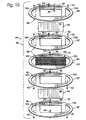
- FIG. 10 An example of a membrane envelope 66 that includes frame members 88 is shown in Fig. 10.
- screen structure 70 is placed in a permeate frame 90 that forms a portion of membrane module 44.
- the screen structure and frame 90 may collectively be referred to as a screen frame or permeate frame 91.
- Permeate gaskets 92 and 92' are attached to permeate frame 90, preferably but not necessarily, by using another thin application of adhesive.
- membranes 46 are attached to screen structure 70 using a thin application of adhesive, such as by spraying or otherwise applying the adhesive to either or both of the membrane and/or screen structure. Care should be taken to ensure that the membranes are flat and firmly attached to the corresponding screen member 73.
- feed plates, or gaskets, 94 and 94' are optionally attached, such as by using another thin application of adhesive.
- the resulting membrane assembly is then stacked with feed, or end, plates to form membrane module 44.
- two or more membrane envelopes may be stacked between the end plates.
- each membrane 46 may be fixed to a frame 104, such as a metal frame and such as shown in Fig. 11. If so, the membrane is fixed to the frame, for instance by ultrasonic welding or another suitable attachment mechanism, and the membrane-frame assembly is then attached to screen structure 70 using adhesive.
- a frame 104 such as a metal frame and such as shown in Fig. 11.
- the membrane is fixed to the frame, for instance by ultrasonic welding or another suitable attachment mechanism, and the membrane-frame assembly is then attached to screen structure 70 using adhesive.
- Other examples of attachment mechanisms for fixing the membrane 46 to a frame 104 achieve gas-tight seals between plates forming membrane envelope 66, as well as between the membrane envelopes, include one or more of brazing, gasketing, and welding.
- the membrane and attached frame may collectively be referred to as a membrane plate 96.
- a mixed gas stream such as reformate stream 36
- the hydrogen gas that permeates through the membranes enters harvesting conduit 69, which is formed between the permeate faces 68 of the membranes.
- the harvesting conduit is in fluid communication with conduits 100 through which the permeate stream may be withdrawn from the membrane envelope.
- the portion of the mixed gas stream that does not pass through the membranes flows to a conduit 98 through which this gas may be withdrawn as byproduct stream 40.
- a single byproduct conduit 98 is shown, while in Fig.
- conduits 98 and 102 are shown to illustrate that any of the conduits described herein may alternatively include more than one fluid passage. It should be understood that the arrows used to indicate the flow of streams 40 and 42 have been schematically illustrated, and that the direction of flow through conduits 98, 100 and 102 may vary, such as depending upon the configuration of a particular membrane module.
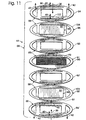
- FIG. 12 another example of a suitable membrane envelope 66 is shown.
- envelope 66 is shown having a generally rectangular form.
- the envelope of Fig. 12 also provides another example of a membrane envelope having a pair of byproduct conduits 98 and 102 and a pair of hydrogen conduits 100.
- envelope 66 includes gaskets or spacer plates 94 as the outer most plates in the stack.
- each of spacer plates includes a frame 106 that defines an inner open region 108.
- Each inner open region 108 couples laterally to conduits 98 and 102.
- Conduits 100 are closed relative to open region 108, thereby isolating the hydrogen-rich stream 42.
- Membrane plates 96 lie adjacent and interior to plates 94.
- Membrane plates 96 each include as a central portion thereof a hydrogen-selective membrane 46, which may be secured to an outer frame 104 that is shown for purposes of illustration. In plates 96, all of the ports are closed relative to membrane 46. Each membrane lies adjacent to a corresponding one of open regions 108, i.e., adjacent to the flow of mixed gas arriving to the envelope. This provides opportunity for hydrogen to pass through the membrane, with the remaining gases, i.e., the gases forming byproduct stream 40, leaving open region 108 through conduit 102.
- Screen plate 91 lies intermediate membrane plates 96, i.e., on the interior or permeate side of each of membranes 46. Screen plate 91 includes a screen structure 70.
- Conduits 98 and 102 are closed relative to the central region of screen plate 91, thereby isolating the byproduct stream 40 and the reformate-rich flow 36 from hydrogen-rich stream 42.
- Conduits 100 are open to the interior region of screen plate 91. Hydrogen, having passed through the adjoining membranes 46, travels along and through screen structure 70 to conduits 100 and eventually to an output port as the hydrogen-rich stream 42.
- membrane module 44 may include one or more membrane envelopes in which the membranes have been adhesively bonded to the screen structure, and/or in which the screen structure includes two or more screen members 83 that are adhesively bonded together.
- the membrane module further includes end plates having input and output ports through which the mixed gas, product (or hydrogen-rich) and byproduct streams are removed from the membrane module.
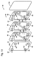
- An example of a suitable membrane module is shown in Fig. 13 in the form of a plate membrane module.
- the module contains end plates 110 between which one or more membrane envelopes 66 are contained. In the illustrated embodiment, three membrane envelopes are shown for purposes of illustration, but it should be understood that more or less envelopes may be used.
- the membrane envelopes are in fluid communication with at least one of the end plates, through which the mixed gas stream is delivered and from which the byproduct 40 and hydrogen-rich 42 streams are removed.
- one of the end plates contains a reformate input port 112 for a mixed gas stream, such as reformate stream 36 or any of the other feeds to the membrane modules discussed herein.
- the end plates further include a pair of exit ports 114 for permeate, or hydrogen-rich, stream 42 and an exit port 116 for byproduct stream 40.
- the number and sizing of the ports for each stream may vary, and that at least one of the ports may be contained on the other end plate or elsewhere on the membrane module, such as on a housing 118 between the end plates, such as shown in Fig. 15.
- the membrane envelopes include conduits 98, 100 and 102 that establish fluid communication with the input and exit ports and between the membrane envelopes. When membrane envelopes 66 are stacked, these various ports align and provide fluid conduits.
- reformate gas is introduced to the membrane module through port 112 and is delivered to the membrane envelopes.
- Hydrogen gas that passes through the hydrogen-selective membranes 46 flows to conduits 100 and is removed from the membrane module through ports 114.
- the rest of the reformate gases namely the portion that does not pass through the hydrogen-selective membranes, flows to conduit 102 and is removed from the membrane module as byproduct stream 40 through part 116.
- Figs. 7-13 the geometry of the frame members, gaskets, membranes and screen members shown in the Figs. 7-13 are provided as illustrative examples, and it should be understood that these components may be of any suitable shape.
- illustrations of circular and rectangular plate membrane envelopes are illustrated in Figs. 10-13 for purposes of illustration.
- Other shapes, and other configurations, such as tubular configurations, are also within the scope of the present invention.
- the configuration and orientation of the passages through the gaskets and plates may vary, depending upon the particular application with which the membrane module will be used.
- Membrane modules containing the palladium alloy membranes that are adhesively bonded to screen structure 70 are subjected to oxidizing conditions to remove the adhesives prior to initial operation of the membrane module. If adhesive is not fully removed prior to operation, the carbon residue from the adhesive can alloy with the palladium-alloy membrane and cause a decline in hydrogen permeability. In extreme cases, carbon alloying with the palladium-alloy membrane can form a brittle alloy that physically fails under operating conditions. Operation of the membrane module does not form a mandatory part of the method of the invention for forming a membrane module.
- the objective of the oxidative conditioning is to burn out the adhesive without excessively oxidizing the palladium-alloy membrane.
- One set of suitable conditions using the above membrane compositions and adhesive is to heat the membrane module to 200° C while passing air over both the feed side and the permeate side of the membrane.
- a preferred method is to heat the membrane module to 200° C while the feed side is pressurized to a pressure greater than the permeate side of the membranes using a slow purge of air (>1 mL/min). Pressures in the range of approximately 50 psig (0.35 MPa) to approximately 200 psig (1.4 MPa) have proven effective. Air at approximately ambient pressure is passed over the permeate side of the membrane at a rate >1 mL/min.
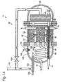
- fuel processor 12 containing a membrane module 44 according to the present invention is shown in Fig. 14.
- fuel processor 12 is shown as a steam reformer 30 that contains reforming catalyst 34.
- reformer 30 may be an autothermal reformer that contains an autothermal reforming catalyst bed.
- fuel processor 12 may be any device adapted to produce hydrogen gas, such as those discussed herein.
- a feed stream 16 is delivered to a vaporization region 150, which as shown contains a vaporization coil 151 in which the feed stream is vaporized.
- a suitable feed stream includes water and a carbon-containing feedstock, such as one or more alcohols or hydrocarbons.
- a carbon-containing feedstock such as one or more alcohols or hydrocarbons.
- the carbon-containing feedstock is miscible with water
- the feedstock and water may be mixed and then vaporized.
- the carbon-containing feedstock is not miscible with water
- the water is typically vaporized and then mixed with the carbon-containing feedstock.
- vaporization coil 151 is contained within the shell 31 of the reformer. It is within the scope of the invention that the vaporization region (and coil) may be located external the shell of the fuel processor, such as extending around the shell or otherwise located outside of the shell.
- the vaporized feed stream is then delivered to hydrogen-producing region 32, which in the context of a reformer, contains at least one reforming catalyst bed.
- the reformate stream which is a mixed gas stream containing hydrogen gas and other gases, 36 is then delivered to membrane module 44, which separates the mixed gas stream into hydrogen-rich stream 42 and byproduct stream 40, as discussed above.
- the illustrated reformer demonstrates that the byproduct stream may be used to provide some or all of the fuel for the reformer's heating assembly 152.
- Heating assembly 152 includes a heating element 153, which in the illustrated embodiment takes the form of a spark plug. Examples of other suitable heating elements include glow plugs, pilot lights, combustion catalysts, resistance heaters, and combinations thereof, such as a glow plug in combination with a combustion catalyst.
- Heating assembly 152 consumes a fuel stream 154, which may be a combustible fuel stream or an electric current, depending upon the type of heating element used in the heating assembly.
- the heating assembly forms part of a combustion chamber, or region, 155, and the fuel stream includes a combustible fuel and air from an air stream 156.
- the fuel may come from an external source, such as schematically illustrated at 157, or may be at least partially formed from the byproduct stream 40 from membrane module 44. It is within the scope of the invention that at least a portion of the fuel stream may also be formed from product hydrogen stream 14.
- the exhaust from combustion region 155 flows through heating conduits 158 in reforming region 32 to provide additional heating to the reforming region.
- Conduits 158 may take a variety of forms, including finned tubes and spirals, to provide sufficient surface area and desirable uniform distribution of heat throughout reforming region 32.
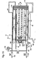
- the reforming region includes a plurality of reforming catalyst tubes 162 that contain reforming catalyst 34.
- the vaporized feed stream from vaporization region 150 is delivered to tubes 162 via a manifold 172 that distributes the feed stream between reforming catalyst tubes.
- the manifold may alternatively be located external shell 31 to enable access to the manifold from external the shell, such as to adjust the relative distribution of the vaporized feed stream between the reforming catalyst tubes.
- portions 160 of the reforming catalyst tubes are also shown extending beyond shell 31.
- the steam reformer of Fig. 15 also provides an example of a fuel processor 12 in which the byproduct stream may be either used as a portion of fuel stream 154 for combustion region 155, vented (such as through pressure-relief valve assembly 164), or delivered through fluid conduit 166 for storage or use outside of fuel processor 12.
- flow regulators 168 for heat produced by heating assembly 152 in combustion region 155 are shown in Fig. 10.
- regulators 168 take the form of apertures in a combustion manifold 170.
- the apertures regulate the path along which combustion exhaust travels from combustion region 155 and through reforming region 32. Examples of suitable placement of the apertures include one or more apertures distal heating assembly 152, and a plurality of apertures distributed along the length of manifold 170.
- the apertures may be evenly spaced, or the openings may be more prevalent distal the burner. Similarly, the size of the apertures may be uniform, or may vary, such as using larger apertures away from heating assembly 152.
- the present invention is applicable in any device in which a stream containing hydrogen gas is purified to produce a purified hydrogen stream.
- the invention is similarly applicable to fuel processing systems in which hydrogen gas is produced from a feed stream and subsequently purified, such as for delivery to a fuel cell stack or other hydrogen-consuming device.
Abstract
Description
- The invention relates generally to hydrogen purification systems and more particularly to methods for forming membrane modules containing a plurality of hydrogen-selective membranes, and hydrogen producing and purifying systems containing the same.
- Hydrogen-selective membranes formed from hydrogen-permeable metals, most notably palladium and alloys of palladium, are known. In particular, planar palladium-alloy membranes have been disclosed for purifying hydrogen gas streams, such as hydrogen gas streams produced by steam reformers, autothermal reformers, partial oxidation reactors, pyrrolysis reactors and other fuel processors, including fuel processors configured to supply purified hydrogen to fuel cells or other processes requiring high-purity hydrogen.
- US-A-5997594 describes a stream reformer having a concentric cylindrical architecture. The reformer includes in concentric relation an outermost metal tube, an inner metal tube, a hydrogen-selective membrane tube, and an innermost metal tube. The tubes are of successively smaller diameter and arranged in concentric relation to one another. An annular combustion region exists in the space within the outermost tube but external of the inner metal tube. An annular reforming region exists within the inner metal tube but external of the membrane tube. An annular hydrogen transport region exists within the membrane tube, but external of the innermost metal tube. A cylindrical polishing region resides within the innermost metal tube.
- Within the reforming region a reforming catalyst reacts with the vaporized mix of methanol and water to produce hydrogen in the vicinity of the membrane tube. The membrane tube is composed of one of a variety of hydrogen-permeable and hydrogen-selective materials including ceramics, carbon, and metals. Especially preferred materials for fabricating the membrane tube are hydrogen-permeable palladium alloys, e.g., palladium alloyed with 35-45 wt % silver. Each end of the membrane tube is sealed by a metal cap. A metal gauze within the reforming region surrounds each cap. A hydrogen stream migrates by pressure differential through the membrane tube and into the hydrogen transport region. A thin membrane tube requires support against deformation under the pressure differential between the reforming region and the hydrogen transport region. For this purpose, a tension spring supports the membrane tube from within while allowing the hydrogen stream to pass by, into and along the transport region.
- A thin palladium alloy membrane, i.e. the hydrogen-selective membrane tube, attaches to the end caps by first attaching a foil, e.g. a copper or nickel foil, to the ends of the tube by ultrasonic welding and then brazing the foil-wrapped ends of the tube to the end caps.
- US-A-5645626 describes a membrane module which comprises a housing fitted with at least one hydrogen separation membrane, at least one feed inlet port, at least one raffinate discharge port, and at least one permeate outlet port. Feed gas enters the module through the feed port and flows over the exterior surfaces of the membrane(s), eventually leaving the module as a hydrogen-depleted raffinate stream. The hydrogen separation membrane is a composite, comprising a coating metal layer, an intermediate layer, and a support matrix. The composite membrane has at least one hole along an axis that is substantially perpendicular to the membrane surfaces. Such an axial hole projects through all three components of the membrane along an axis that is essentially common to all three components and intersects the network of voids in the support matrix, thereby providing a conduit for permeate hydrogen from the support matrix to flow out of the membrane module, exiting the module through the permeate discharge port.
- To be economical, palladium and palladium-alloy membranes must be thin. For example, planar membranes are typically approximately 25 µm (0.001 inches) thick. However, these extremely thin membranes are subject to wrinkling during assembly into a membrane module containing one or more hydrogen-selective membranes. A membrane that has one or more wrinkles is subject to premature failure due to stress fractures forming at the wrinkle. When such a failure occurs, impurities that otherwise would be unable to pass through the membrane can now pass through the membrane, thereby reducing the purity of the product hydrogen stream and potentially damaging the fuel cell stack or other hydrogen-consuming device with which the purified stream is used.
- Therefore, there is a need for a method for preparing hydrogen-selective membranes for use in a fuel processor or other hydrogen-purifying device without wrinkling the membranes.
- The present invention is directed in particular to methods for preparing membrane modules that contain one or more hydrogen-selective membranes. The membrane modules include a pair of hydrogen-selective membranes mounted on a support, of which a variety of embodiments are disclosed. In the preparation, the membranes are adhesively mounted on the screen structure during assembly. The method and embodiments thereof are set forth in the claims, as is other subject matter of the invention.
-
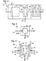
- Fig. 1 is a schematic diagram of a fuel cell system containing a fuel processor with a membrane module obtainable by a method according to the present invention.
- Fig. 2 is a schematic diagram of another embodiment of the fuel cell system of Fig. 1.
- Fig. 3 is a schematic diagram of a fuel processor suitable for use in the fuel cell systems of Figs. 1 and 2 and including a membrane module obtainable by a method according to the present invention.
- Fig. 4 is a schematic diagram of another embodiment of the fuel processor of Fig. 3.
- Fig. 5 is a schematic diagram of a hydrogen purifier containing a membrane module obtainable by a method according to the present invention.
- Fig. 6 is a fragmentary side elevation view of a membrane envelope obtainable by a method according to the present invention and including a screen structure.
- Fig. 7 is an exploded isometric view of another embodiment of a membrane envelope obtainable by a method according to the present invention and including a screen structure having several layers.
- Fig. 8 is a cross-sectional view of the membrane envelope of Fig. 7.
- Fig. 9 is a fragmentary isometric view of an expanded metal screen member suitable for use in the screen structure of Fig. 7.
- Fig. 10 is an exploded isometric view of another membrane envelope obtainable by a method according to the present invention.
- Fig. 11 is an exploded isometric view of another membrane envelope obtainable by a method according to the present invention.
- Fig. 12 is an exploded isometric view of another membrane envelope obtainable by a method according to the present invention.
- Fig. 13 is an exploded isometric view of another membrane module obtainable by a method according to the present invention.
- Fig. 14 is a cross-sectional view of a fuel processor that includes a membrane module obtainable by a method according to the present invention.
- Fig. 15 is a cross-sectional view of another fuel processor that includes a membrane module obtainable by a method according to the present invention.
-
- A fuel cell system obtainable by a method according to the present invention is shown in Fig. 1 and generally indicated at 10.
System 10 includes at least onefuel processor 12 and at least onefuel cell stack 22.Fuel processor 12 is adapted to produce aproduct hydrogen stream 14 containing hydrogen gas from afeed stream 16 containing a feedstock. The fuel cell stack is adapted to produce an electric current from the portion ofproduct hydrogen stream 14 delivered thereto. In the illustrated embodiment, asingle fuel processor 12 and a singlefuel cell stack 22 are shown and described, however, it should be understood that more than one of either or both of these components may be used. It should also be understood that these components have been schematically illustrated and that the fuel cell system may include additional components that are not specifically illustrated in the figures, such as feed pumps, air delivery systems, heat exchangers, heating assemblies and the like. -
Fuel processor 12 produces hydrogen gas through any suitable mechanism. Examples of suitable mechanisms include steam reforming and autothermal reforming, in which reforming catalysts are used to produce hydrogen gas from a feed stream containing a carbon-containing feedstock and water. Other suitable mechanisms for producing hydrogen gas include pyrrolysis and catalytic partial oxidation of a carbon-containing feedstock, in which case the feed stream does not contain water. Still another suitable mechanism for producing hydrogen gas is electrolysis, in which case the feedstock is water. For purposes of illustration, the following discussion will describefuel processor 12 as a steam reformer adapted to receive afeed stream 16 containing a carbon-containingfeedstock 18 andwater 20. However, it is within the scope of the invention that thefuel processor 12 may take other forms, as discussed above. - Examples of suitable carbon-containing feedstocks include at least one hydrocarbon or alcohol. Examples of suitable hydrocarbons include methane, propane, natural gas, diesel, kerosene, gasoline and the like. Examples of suitable alcohols include methanol, ethanol, and polyols, such as ethylene glycol and propylene glycol.
-
Feed stream 16 may be delivered tofuel processor 12 via any suitable mechanism. Although only asingle feed stream 16 is shown in Fig. 1, it should be understood that more than onestream 16 may be used and that these streams may contain the same or different components. When carbon-containingfeedstock 18 is miscible with water, the feedstock is typically delivered with the water component offeed stream 16, such as shown in Fig. 1. When the carbon-containing feedstock is immiscible or only slightly miscible with water, these components are typically delivered tofuel processor 12 in separate streams, such as shown in Fig. 2. - In Figs. 1 and 2, feed
stream 16 is shown being delivered tofuel processor 12 by a feedstream delivery system 17.Delivery system 17 includes any suitable mechanism, device, or combination thereof that delivers the feed stream to fuelprocessor 12. For example, the delivery system may include one or more pumps that deliver the components ofstream 16 from a supply. Additionally, or alternatively,system 17 may include a valve assembly adapted to regulate the flow of the components from a pressurized supply. The supplies may be located external of the fuel cell system, or may be contained within or adjacent the system. -
Fuel cell stack 22 contains at least one, and typically multiple, fuel cells 24 adapted to produce an electric current from the portion of theproduct hydrogen stream 14 delivered thereto. This electric current may be used to satisfy the energy demands, or applied load, of an associated energy-consumingdevice 25. Illustrative examples ofdevices 25 include, but should not be limited to, a motor vehicle, recreational vehicle, boat, tool, light or lighting assemblies, appliances (such as household or other appliances), household, signaling or communication equipment, etc. It should be understood thatdevice 25 is schematically illustrated in Fig. 1 and is meant to represent one or more devices or collection of devices that are adapted to draw electric current from the fuel cell system. A fuel cell stack typically includes multiple fuel cells joined together betweencommon end plates 23, which contain fluid delivery/removal conduits (not shown). Examples of suitable fuel cells include proton exchange membrane (PEM) fuel cells and alkaline fuel cells.Fuel cell stack 22 may receive all ofproduct hydrogen stream 14. Some or all ofstream 14 may additionally, or alternatively, be delivered, via a suitable conduit, for use in another hydrogen-consuming process, burned for fuel or heat, or stored for later use. -
Fuel processor 12 is any suitable device that produces hydrogen gas. Preferably, the fuel processor is adapted to produce substantially pure hydrogen gas, and even more preferably, The fuel processor is adapted to produce pure hydrogen gas. For the purposes of the present invention, substantially pure hydrogen gas is greater than 90% pure, preferably greater than 95% pure, more preferably greater than 99% Pure, and even more preferably greater than 99.5% pure. Suitable fuel processors are disclosed in U.S. Patent Nos. 5,997,594 and 5,861,137. - An example of a
suitable fuel processor 12 is a steam reformer. An example of a suitable steam reformer is shown in Fig. 3 and indicated generally at 30.Reformer 30 includes a reforming, or hydrogen-producing,region 32 that includes asteam reforming catalyst 34. Alternatively,reformer 30 may be an autothennal reformer that includes an autothecmal reforming catalyst, In reformingregion 32, areformate stream 36 is produced from the water and carbon-containing feedstock formingfeed stream 16. The reformate stream typically contains hydrogen gas and impurities, and therefore is delivered to a separation region, or purification region, 38, where the hydrogen gas is purified. Inseparation region 38, the hydrogen-containing stream is separated into one or more byproduct streams, which are collectively illustrated at 40, and a hydrogen-rich stream 42 by any suitable pressure-driven separation process. In Fig. 3, hydrogen-rich stream 42 is shown formingproduct hydrogen stream 14.Separation region 38 includes amembrane module 44 according to the present invention and contains one or more hydrogen-selective membranes 46.Membrane module 44 is discussed and illustrated in more detail subsequently. -
Reformer 30 may, but does not necessarily, further include a polishingregion 48, such as shown in Fig.4.Polishing region 48 receives hydrogen-rich stream 42 fromseparation region 38 and further purifies the stream by reducing the concentration of, or removing, selected compositions therein. For example, whenstream 42 is intended for use in a fuel cell stack, such asstack 22, compositions that may damage the fuel cell stack, such as carbon monoxide and carbon dioxide, may be removed from the hydrogen-rich stream. The concentration of carbon monoxide should be less than 10 ppm (parts per million) to prevent the control system from isolating the fuel cell stack. Preferably, the system limits the concentration of carbon monoxide to less than 5 ppm, and even more preferably, to less than 1 ppm. The concentration of carbon dioxide may be greater than that of carbon monoxide. For example, concentrations of less than 25% carbon dioxide may be acceptable. Preferably, the concentration is less than 10%, even more preferably, less than 1%. Especially preferred concentrations are less than 50 ppm. It should be understood that the acceptable minimum concentrations presented herein are illustrative examples, and that concentrations other than those presented herein may be used and are within the scope of the present invention. For example, particular users or manufacturers may require minimum or maximum concentration levels or ranges that are different than those identified herein. -
Region 48 includes any suitable structure for removing or reducing the concentration of the selected compositions instream 42. For example, when the product stream is intended for use in a PEM fuel cell stack or other device that will be damaged if the stream contains more than determined concentrations of carbon monoxide or carbon dioxide, it may be desirable to include at least onemethanation catalyst bed 50.Bed 50 converts carbon monoxide and carbon dioxide into methane and water, both of which will not damage a PEM fuel cell stack.Polishing region 48 may also include another hydrogen-producingdevice 52, such as another reforming catalyst bed, to convert any unreacted feedstock into hydrogen gas. In such an embodiment, it is preferable that the second reforming catalyst bed is upstream from the methanation catalyst bed so as not to reintroduce carbon dioxide or carbon monoxide downstream of the methanation catalyst bed. - Steam reformers typically operate at temperatures in the range. of 200° C and 700° C, and at pressures in the range of 50 psi and 1000 psi (0.35 MPa and 6.9 MPa), although temperatures outside of this range are within the scope of the invention, such as depending upon the particular type and configuration of fuel processor being used. Any suitable heating mechanism or device may be used to provide this heat, such as a heater, burner, combustion catalyst, or the like. The heating assembly may be external the fuel processor or may form a combustion chamber that forms part of the fuel processor. The fuel for the heating assembly may be provided by the fuel processing system, or fuel cell system, by an external source, or both.
- In Figs. 3 and 4,
reformer 30 is shown including ashell 31 in which the above-described components are contained.Shell 31, which also may be referred to as a housing, enables the fuel processor, such asreformer 30, to be moved as a unit. It also protects the components of the fuel processor from damage by providing a protective enclosure and reduces the heating demand of the fuel processor because the components of the fuel processor may be heated as a unit.Shell 31 may, but does not necessarily, include insulatingmaterial 33, such as a solid insulating material, blanket insulating material, or an air-filled cavity. It is within the scope of the invention, however, that the reformer may be formed without a housing or shell. Whenreformer 30 includes insulatingmaterial 33, the insulating material may be internal the shell, external the shell, or both. When the insulating material is external a shell containing the above-described reforming, separation and/or polishing regions, the fuel processor may further include an outer cover or jacket external the insulation. - It is further within the scope of the invention that one or more of the components may either extend beyond the shell or be located external at
least shell 31. For example, and as schematically illustrated in Fig. 4, polishingregion 48 may beexternal shell 31 and/or a portion of reformingregion 32 may extend beyond the shell. - Although
fuel processor 12, feedstream delivery system 17,fuel cell stack 22 and energy-consumingdevice 25 may all be formed from one or more discrete components, it is also within the scope of the invention that two or more of these devices may be integrated, combined or otherwise assembled within an external housing or body. For example, a fuel processor and feed stream delivery system may be combined to provide a hydrogen-producing device with an on-board, or integrated, feed stream delivery system, such as schematically illustrated at 26 in Fig. 1. Similarly, a fuel cell stack may be added to provide an energy-generating device with an integrated feed stream delivery system, such as schematically illustrated at 27 in Fig. 1. -
Fuel cell system 10 may additionally be combined with an energy-consuming device, such asdevice 25, to provide the device with an integrated, or on-board, energy source. For example, the body of such a device is schematically illustrated in Fig. 1 at 28. Examples of such devices include a motor vehicle, such as a recreational vehicle, automobile, boat or other seacraft, and the like, a dwelling, such as a house, apartment, duplex, apartment complex, office, store or the like, or a self-contained equipment, such as an appliance, light, tool, microwave relay station, transmitting assembly, remote signaling or communication equipment, etc. - It is within the scope of the invention that the above-described
fuel processor 12 may be used independent of a fuel cell stack. In such an embodiment, the system may be referred to as a fuel processing system, and it may be used to provide a supply of pure or substantially pure hydrogen to a hydrogen-consuming device, such as a burner for heating, cooking or other applications. Similar to the above discussion about integrating the fuel cell system with an energy-consuming device, the fuel processor and hydrogen-consuming device may be combined, or integrated. - It is also within the scope of the present invention that the membrane modules obtainable by a method disclosed herein may be used as a hydrogen purifier independent of a fuel processor or fuel cell stack. An example of a
membrane module 44 configured for use as a hydrogen-purifier is schematically illustrated in Fig. 5 and generally indicated at 60. As shown, amixed gas stream 61 containinghydrogen gas 62 andother gases 63 is delivered topurifier 60, which contains amembrane module 44 constructed according to the present invention. The membrane module contains at least one hydrogen-selective membrane 46, and separates the mixed gas stream into aproduct stream 64 containing at least substantially hydrogen gas and abyproduct stream 65 containing at least substantially the other gases. Another way to describe the purifier is that the product stream contains at least a substantial portion of the hydrogen gas in the mixed gas stream and that the byproduct stream contains at least a substantial portion of the other gases. Similar to the fuel processors and fuel cell systems discussed above,purifier 60 may be integrated with a hydrogen-producing device to provide a hydrogen-producing device with an integrated hydrogen purifier and/or with a hydrogen-consuming device to provide a hydrogen-consuming device with an integrated hydrogen purifier. - It should be understood that the hydrogen purity of the product stream, the hydrogen content of the byproduct stream, the percentage of hydrogen from the mixed gas stream that forms the byproduct stream, and similar compositions of the product and byproduct streams may be selectively varied depending upon the construction of the membrane module and/or the operating conditions within which the membrane module is used. For example, the compositions of the product and byproduct streams may vary at least partially in response to at least the following factors: the temperature of the membrane module, the pressure of the membrane module, the composition of the hydrogen-selective membrane, the state of wear of the hydrogen-selective membrane, the thickness of the hydrogen-selective membrane, the composition of the mixed gas stream, the number of hydrogen-selective membranes used in the membrane module, and the number of sequential membranes through which the mixed gas, product and/or byproduct streams may pass.
- As discussed, a suitable structure for use in
separation region 38 is amembrane module 44, which contains one or more hydrogen-peameable and hydrogen-selective membranes 46. The membranes may be formed of any hydrogen-selective material suitable for use in the operating environment and conditions in which the membrane module is operated, such as in a purifier, fuel processor or the like. Examples of suitable materials formembranes 46 are palladium and palladium alloys, and especially thin films of such metals and metal alloys. Palladium alloys have proven particularly effective, especially palladium with 35 wt% to 45 wt% copper. These membranes are typically formed from a thin foil that is approximately 0.001 inches (25 µm) thick. It is within the scope of the present invention, however, that the membranes may be formed from hydrogen-selective metals and metal alloys other than those discussed above and that the membranes may have thicknesses that are larger or smaller than discussed above. For example, the membrane may be made thinner, with commensurate increase in hydrogen flux. Suitable mechanisms for reducing the thickness of the membrane include rolling, sputtering and etching. A suitable etching process is disclosed in U.S. Patent Application Serial No. 09/274,154, which was filed on March 22, 1999, is entitled "Hydrogen-Permeable Metal Membrane and Method for Producing the Same," and the complete disclosure of which is hereby incorporated by reference. - The hydrogen-permeable membranes may be arranged in pairs around a common permeate channel to form a membrane envelope, as is disclosed in the incorporated patent applications and as schematically illustrated in Fig. 6 at 66. In such a configuration, the membrane pairs may be referred to as a membrane envelope, in that they define a common permeate channel, or harvesting conduit, through which the permeated gas may be collected and removed to form hydrogen-rich stream 42 (or
product hydrogen stream 14 or purifiedhydrogen stream 64, depending on the particular implementation of the membrane module). - It should be understood that the membrane pairs may take a variety of suitable shapes, such as planar envelopes and tubular envelopes. Similarly, the membranes may be independently supported, such as with respect to an end plate or around a central passage. For purposes of illustration, the following description and associated illustrations will describe the membrane module as including one or
more membrane envelopes 66. It should be understood that the membranes forming the envelope may be two separate membranes, or may be a single membrane folded, rolled or otherwise configured to define two membrane regions, or surfaces, 67 with permeate faces 68 that are oriented toward each other to define aconduit 69 therebetween from which the permeate gas may be collected and withdrawn. - To support the membranes against high feed pressures, a support, or screen structure, 70 is used.
Screen structure 70 provides support to the hydrogen-selective membranes, and more particularly includessurfaces 71 against which the permeate sides 68 of the membranes are be supported.Screen structure 70 also defines harvestingconduit 69, through which permeated gas may flow both transverse and parallel to the surface of the membrane through which the gas passes, such as schematically illustrated in Fig. 6. The permeate gas, which is at least substantially pure hydrogen gas, may then be harvested or otherwise withdrawn from the membrane module, such as to formstreams - To reiterate, the membrane module discussed herein may include one or
more membrane envelopes 66, typically along with suitable input and output ports through which the mixed gas stream, such asreformate stream 36 ormixed gas stream 61, is delivered to the membrane module and from which the hydrogen-rich and byproduct streams are removed. In some embodiments, the membrane module may include a plurality of membrane envelopes. When the membrane module includes a plurality of membrane envelopes, the module may include fluid conduits interconnecting the envelopes, such as to deliver a mixed gas stream thereto, to withdraw purified hydrogen gas therefrom, and/or to withdraw the gas that does not pass through the membranes from the membrane module. When the membrane module includes a plurality of membrane envelopes, the permeate stream, byproduct stream, or both, from a first membrane envelope may be sent to another membrane envelope for further purification. - An embodiment of a
suitable screen structure 70 is shown in Figs. 7 and 8 and generally indicated at 72.Screen structure 72 includesplural screen members 73. In the illustrated embodiment, the screen members include acoarse mesh screen 74 sandwiched between fine mesh screens 76. It should be understood that the terms "fine" and "coarse" are relative terms. Preferably, the outer screen members are selected to supportmembranes 46 without piercing the membranes and without having sufficient apertures, edges or other projections that may pierce, weaken or otherwise damage the membrane under the operation conditions with which the membrane module is used. Because the screen structure needs to provide for flow of the permeated gas generally parallel to the membranes, it is preferable to use a relatively coarser inner screen member to provide for enhanced parallel flow conduits. In other words, the finer mesh screens provide better protection for the membranes, while the coarser mesh screen provides better flow generally parallel to the membranes. - According to the method of the present invention, an adhesive, such as a contact adhesive, is used to secure
membranes 46 to the screen structure during fabrication. An example of a suitable adhesive is sold by 3M under the trade name SUPER 77. An adhesive may additionally or alternatively be used to adhere the fine mesh screens tocoarse mesh screen 74 during assembly. In Fig. 7,reference numerals membrane 46 withscreen structure 70 andindividual screen members 73. It should be understood thatadhesives - The use of adhesive 78 allows the sandwiched screen structure to be retained as a unit in a selected configuration, such as the flat, planar configuration shown in Figs. 7 and 8. The use of adhesive 80 allows the thin membranes to be firmly attached to the screen structure without any wrinkles in the membrane. It is. important that these components be held flat and in close contact during assembly of the membrane module. If the membrane buckles, or if the screen structure buckles, then a wrinkle will form in the membrane during use. Similarly, if the membranes are improperly positioned relative to the screen structure, wrinkles may also occur, such as when the membrane module is pressurized. As pointed out above, wrinkles in the membrane lead to stress fractures and fatigue fractures, causing failure of the membrane module and contamination of the purified gas stream.
- In practice, a light coating of contact adhesive 78 is sprayed or otherwise applied to the two opposing major surfaces of the
coarse mesh screen 74 and then fine mesh screens 76 are attached, one to each major surface of the coarse screen.Adhesive 78 holdsscreen structure 72 together. Alternatively, the adhesive may be applied toscreens 76 instead of being applied to the coarse screen. Similarly, adhesive 80 is applied between the corresponding surfaces of the fine mesh screens and hydrogen-selective membranes 46 may then be adhesively secured to the opposed surfaces of the fine mesh screens. As discussed herein, the adhesive is at least substantially, or completely, removed after fabrication of the membrane envelope and/or membrane modules so as to not interfere with the operation of the membrane envelopes. - It is within the scope of the invention that the screen members may be of similar or the same construction, and that more or fewer screen members may be used. It is also within the scope of the invention that any suitable supporting medium that enables permeated gas to flow in the harvesting conduit generally parallel and transverse to the membranes may be used. For example, porous ceramics, porous carbon, porous metal, ceramic foam, carbon foam, and metal foam may be used to form
screen structure 70, either alone, or in combination with one ormore screen members 73. As another example, fine mesh screens 76 may be formed from expanded metal instead of a woven mesh material. Preferably,screen structure 70 is formed from a corrosion-resistant material that will not impair the operation of the membrane. module and devices with which the membrane module is used. Examples of suitable materials for metallic screen members include stainless steels, titanium and alloys thereof, zirconium and alloys thereof, corrosion-resistant alloys, including Inconel™ alloys, such as 800H™, and Hastelloy™ alloys, and alloys of copper and nickel, such as Monel™. - An example of an expanded metal screen member is shown in Fig. 9 and generally indicated at 82. Expanded metal sheets include a
latticework 83 of metal that defines a plurality ofapertures 84 through which permeated gas may flow. Although other processes may be used, expanded metal sheets may be formed from scoring a sheet of metal and then stretching the metal to provide apertures, such asapertures 84 at the scores. It should be understood that the expanded metal screen member has been schematically illustrated in Fig. 9, and that the actual shape of the apertures may vary and will often have shapes that generally resemble diamonds, parallelograms or other geometric shapes, for example as shown in Fig. 12. The sheet may also include asolid perimeter region 86, which is advantageous because it is free from projections, burrs, or other wire ends that may be present in woven mesh screen members and which may pierce or otherwise damage the hydrogen-selective membranes. Although only a portion of expandedmetal screen member 82 is shown in Fig. 9, theperimeter region 86 of the screen member may extend all the way around the screen member. Alternatively, only the perimeter regions that contactmembranes 46 may be solid surfaces. - All of the foregoing metallic screen compositions may include a
coating 85 on surface 71 (such as shown in Fig. 6). Examples of suitable coatings include aluminum oxide, tungsten carbide, tungsten nitride, titanium carbide, titanium nitride, and mixtures thereof. These coatings are generally characterized as being thermodynamically stable with respect to decomposition in the presence of hydrogen. Suitable coatings are formed from materials, such as oxides, nitrides, carbides, or intermetallic compounds, that can be applied as a coating and which are thermodynamically stable with respect to decomposition in the presence of hydrogen under the operating parameters (temperature, pressure, etc.) in which the membrane module will be subjected. Alternatively, the coating may be applied to an expanded metal screen member that is used in place of a fine mesh screen, in which case the coating would be applied to at least the surface of the expanded mesh that will contact the hydrogen-selective membrane 46. Suitable methods for applying such coatings to the screen or expanded metal screen member include chemical vapor deposition, sputtering, thermal evaporation, thermal spraying, and, in the case of at least aluminum oxide, deposition of the metal (e.g., aluminum) followed by oxidation of the metal to give aluminum oxide. In at least some embodiments, the coatings may be described as preventing intermetallic diffusion between the hydrogen-selective membranes and the screen structure. - Preferably, the screen structure and membranes are incorporated into a membrane module that includes
frame members 88 that are adapted to seal, support and/or interconnect the membrane envelopes for use in fuel processing systems, gas purification systems, and the like. Finemesh metal screen 76 fits withinpermeate frame 90. Expandedmetal screen member 86 may either fit withinpermeate frame 90 or extend at least partially over the surface ofpermeate frame 90. Examples ofsuitable frame members 88 include supporting frames and/or gaskets. These frames, gaskets or other support structures may also define, at least in part, the fluid conduits that interconnect the membrane envelopes in an embodiment ofmembrane module 44 that contains two or more membrane envelopes. Examples of suitable gaskets are flexible graphite gaskets, although other materials may be used, such as depending upon the operating conditions in which a particular membrane module is used. - An example of a
membrane envelope 66 that includesframe members 88 is shown in Fig. 10. As shown,screen structure 70 is placed in apermeate frame 90 that forms a portion ofmembrane module 44. The screen structure andframe 90 may collectively be referred to as a screen frame or permeateframe 91.Permeate gaskets 92 and 92' are attached to permeateframe 90, preferably but not necessarily, by using another thin application of adhesive. Next,membranes 46 are attached to screenstructure 70 using a thin application of adhesive, such as by spraying or otherwise applying the adhesive to either or both of the membrane and/or screen structure. Care should be taken to ensure that the membranes are flat and firmly attached to thecorresponding screen member 73. Finally, feed plates, or gaskets, 94 and 94' are optionally attached, such as by using another thin application of adhesive. The resulting membrane assembly is then stacked with feed, or end, plates to formmembrane module 44. Optionally, two or more membrane envelopes may be stacked between the end plates. - Optionally, each
membrane 46 may be fixed to aframe 104, such as a metal frame and such as shown in Fig. 11. If so, the membrane is fixed to the frame, for instance by ultrasonic welding or another suitable attachment mechanism, and the membrane-frame assembly is then attached to screenstructure 70 using adhesive. Other examples of attachment mechanisms for fixing themembrane 46 to aframe 104 achieve gas-tight seals between plates formingmembrane envelope 66, as well as between the membrane envelopes, include one or more of brazing, gasketing, and welding. The membrane and attached frame may collectively be referred to as amembrane plate 96. - For purposes of illustration, the geometry of fluid flow through
membrane envelope 66 is described with respect to the embodiment ofenvelope 66 shown in Fig. 10. As shown, a mixed gas stream, such asreformate stream 36, is delivered to the membrane envelope and contacts theouter surfaces 97 ofmembranes 46. The hydrogen gas that permeates through the membranes enters harvestingconduit 69, which is formed between the permeate faces 68 of the membranes. The harvesting conduit is in fluid communication withconduits 100 through which the permeate stream may be withdrawn from the membrane envelope. The portion of the mixed gas stream that does not pass through the membranes flows to aconduit 98 through which this gas may be withdrawn asbyproduct stream 40. In Fig. 10, asingle byproduct conduit 98 is shown, while in Fig. 11 a pair ofconduits streams conduits - In Fig. 12, another example of a
suitable membrane envelope 66 is shown. For purposes of illustration,envelope 66 is shown having a generally rectangular form. The envelope of Fig. 12 also provides another example of a membrane envelope having a pair ofbyproduct conduits hydrogen conduits 100. As shown,envelope 66 includes gaskets orspacer plates 94 as the outer most plates in the stack. Generally, each of spacer plates includes aframe 106 that defines an inneropen region 108. Each inneropen region 108 couples laterally toconduits Conduits 100, however, are closed relative to openregion 108, thereby isolating the hydrogen-rich stream 42.Membrane plates 96 lie adjacent and interior toplates 94.Membrane plates 96 each include as a central portion thereof a hydrogen-selective membrane 46, which may be secured to anouter frame 104 that is shown for purposes of illustration. Inplates 96, all of the ports are closed relative tomembrane 46. Each membrane lies adjacent to a corresponding one ofopen regions 108, i.e., adjacent to the flow of mixed gas arriving to the envelope. This provides opportunity for hydrogen to pass through the membrane, with the remaining gases, i.e., the gases formingbyproduct stream 40, leavingopen region 108 throughconduit 102.Screen plate 91 liesintermediate membrane plates 96, i.e., on the interior or permeate side of each ofmembranes 46.Screen plate 91 includes ascreen structure 70.Conduits screen plate 91, thereby isolating thebyproduct stream 40 and the reformate-rich flow 36 from hydrogen-rich stream 42.Conduits 100 are open to the interior region ofscreen plate 91. Hydrogen, having passed through the adjoiningmembranes 46, travels along and throughscreen structure 70 toconduits 100 and eventually to an output port as the hydrogen-rich stream 42. - As discussed,
membrane module 44 may include one or more membrane envelopes in which the membranes have been adhesively bonded to the screen structure, and/or in which the screen structure includes two ormore screen members 83 that are adhesively bonded together. Typically, the membrane module further includes end plates having input and output ports through which the mixed gas, product (or hydrogen-rich) and byproduct streams are removed from the membrane module. An example of a suitable membrane module is shown in Fig. 13 in the form of a plate membrane module. As shown, the module containsend plates 110 between which one ormore membrane envelopes 66 are contained. In the illustrated embodiment, three membrane envelopes are shown for purposes of illustration, but it should be understood that more or less envelopes may be used. The membrane envelopes are in fluid communication with at least one of the end plates, through which the mixed gas stream is delivered and from which thebyproduct 40 and hydrogen-rich 42 streams are removed. - As shown in the illustrative embodiment of Fig. 13, one of the end plates contains a
reformate input port 112 for a mixed gas stream, such asreformate stream 36 or any of the other feeds to the membrane modules discussed herein. The end plates further include a pair ofexit ports 114 for permeate, or hydrogen-rich,stream 42 and anexit port 116 forbyproduct stream 40. It should be understood that the number and sizing of the ports for each stream may vary, and that at least one of the ports may be contained on the other end plate or elsewhere on the membrane module, such as on ahousing 118 between the end plates, such as shown in Fig. 15. As shown, the membrane envelopes includeconduits membrane envelopes 66 are stacked, these various ports align and provide fluid conduits. - In operation, reformate gas is introduced to the membrane module through
port 112 and is delivered to the membrane envelopes. Hydrogen gas that passes through the hydrogen-selective membranes 46 flows toconduits 100 and is removed from the membrane module throughports 114. The rest of the reformate gases, namely the portion that does not pass through the hydrogen-selective membranes, flows toconduit 102 and is removed from the membrane module asbyproduct stream 40 throughpart 116. - It should be understood that the geometry of the frame members, gaskets, membranes and screen members shown in the Figs. 7-13 are provided as illustrative examples, and it should be understood that these components may be of any suitable shape. For example, illustrations of circular and rectangular plate membrane envelopes are illustrated in Figs. 10-13 for purposes of illustration. Other shapes, and other configurations, such as tubular configurations, are also within the scope of the present invention. Similarly, the configuration and orientation of the passages through the gaskets and plates may vary, depending upon the particular application with which the membrane module will be used.
- Membrane modules containing the palladium alloy membranes that are adhesively bonded to screen
structure 70 are subjected to oxidizing conditions to remove the adhesives prior to initial operation of the membrane module. If adhesive is not fully removed prior to operation, the carbon residue from the adhesive can alloy with the palladium-alloy membrane and cause a decline in hydrogen permeability. In extreme cases, carbon alloying with the palladium-alloy membrane can form a brittle alloy that physically fails under operating conditions. Operation of the membrane module does not form a mandatory part of the method of the invention for forming a membrane module. - The objective of the oxidative conditioning is to burn out the adhesive without excessively oxidizing the palladium-alloy membrane. One set of suitable conditions using the above membrane compositions and adhesive is to heat the membrane module to 200° C while passing air over both the feed side and the permeate side of the membrane. A preferred method is to heat the membrane module to 200° C while the feed side is pressurized to a pressure greater than the permeate side of the membranes using a slow purge of air (>1 mL/min). Pressures in the range of approximately 50 psig (0.35 MPa) to approximately 200 psig (1.4 MPa) have proven effective. Air at approximately ambient pressure is passed over the permeate side of the membrane at a rate >1 mL/min. These conditions are maintained for approximately 15-25 hours. Then the temperature is increased to 400° C, while maintaining air pressure and flow rate over the feed and permeate sides of the membranes. The temperature is held at 400° C for approximately 2-5 hours. After completing this oxidative conditioning of the membrane module, the adhesive has been burned out of the membrane module and the module is ready to accept a hydrogen-containing feed stream to be purified. Experiments have shown that these methods result in membrane modules containing membranes that are free of wrinkles and without excessive carbon contamination.
- It should be understood that the conditions described above were presented to provide an illustrative example and that the operating conditions may vary. For example, different conditions may be used because of such factors as different membrane compositions, different membrane thicknesses, and different adhesives. Similarly, the invented method using an adhesive to secure hydrogen-selective membranes on one or more support screens may be used with purification assemblies other than the fuel processing assemblies described herein and in the incorporated patent applications.
- An example of a
fuel processor 12 containing amembrane module 44 according to the present invention is shown in Fig. 14. In the illustrated embodiment,fuel processor 12 is shown as asteam reformer 30 that contains reformingcatalyst 34. Alternatively,reformer 30 may be an autothermal reformer that contains an autothermal reforming catalyst bed. It should be understood thatfuel processor 12 may be any device adapted to produce hydrogen gas, such as those discussed herein. - In the embodiment of
steam reformer 30 shown in Fig. 14, afeed stream 16 is delivered to avaporization region 150, which as shown contains avaporization coil 151 in which the feed stream is vaporized. For a steam reformer, a suitable feed stream includes water and a carbon-containing feedstock, such as one or more alcohols or hydrocarbons. When the carbon-containing feedstock is miscible with water, the feedstock and water may be mixed and then vaporized. When the carbon-containing feedstock is not miscible with water, the water is typically vaporized and then mixed with the carbon-containing feedstock. In the illustrated embodiment,vaporization coil 151 is contained within theshell 31 of the reformer. It is within the scope of the invention that the vaporization region (and coil) may be located external the shell of the fuel processor, such as extending around the shell or otherwise located outside of the shell. - The vaporized feed stream is then delivered to hydrogen-producing
region 32, which in the context of a reformer, contains at least one reforming catalyst bed. The reformate stream, which is a mixed gas stream containing hydrogen gas and other gases, 36 is then delivered tomembrane module 44, which separates the mixed gas stream into hydrogen-rich stream 42 andbyproduct stream 40, as discussed above. The illustrated reformer demonstrates that the byproduct stream may be used to provide some or all of the fuel for the reformer'sheating assembly 152.Heating assembly 152 includes aheating element 153, which in the illustrated embodiment takes the form of a spark plug. Examples of other suitable heating elements include glow plugs, pilot lights, combustion catalysts, resistance heaters, and combinations thereof, such as a glow plug in combination with a combustion catalyst. -
Heating assembly 152 consumes afuel stream 154, which may be a combustible fuel stream or an electric current, depending upon the type of heating element used in the heating assembly. In the illustrated embodiment, the heating assembly forms part of a combustion chamber, or region, 155, and the fuel stream includes a combustible fuel and air from anair stream 156. The fuel may come from an external source, such as schematically illustrated at 157, or may be at least partially formed from thebyproduct stream 40 frommembrane module 44. It is within the scope of the invention that at least a portion of the fuel stream may also be formed fromproduct hydrogen stream 14. In the illustrated embodiment, the exhaust fromcombustion region 155 flows throughheating conduits 158 in reformingregion 32 to provide additional heating to the reforming region.Conduits 158 may take a variety of forms, including finned tubes and spirals, to provide sufficient surface area and desirable uniform distribution of heat throughout reformingregion 32. - In Fig. 15, another illustrative example of a steam reformer containing a
membrane module 44 obtainable by a method according to the present invention is shown. As shown, the reforming region includes a plurality of reformingcatalyst tubes 162 that contain reformingcatalyst 34. The vaporized feed stream fromvaporization region 150 is delivered totubes 162 via a manifold 172 that distributes the feed stream between reforming catalyst tubes. As shown in dashed lines in Fig. 15, the manifold may alternatively be locatedexternal shell 31 to enable access to the manifold from external the shell, such as to adjust the relative distribution of the vaporized feed stream between the reforming catalyst tubes. Similarly,portions 160 of the reforming catalyst tubes are also shown extending beyondshell 31. - The steam reformer of Fig. 15 also provides an example of a
fuel processor 12 in which the byproduct stream may be either used as a portion offuel stream 154 forcombustion region 155, vented (such as through pressure-relief valve assembly 164), or delivered throughfluid conduit 166 for storage or use outside offuel processor 12. Also shown in Fig. 10 areflow regulators 168 for heat produced byheating assembly 152 incombustion region 155. In the illustrated embodiment,regulators 168 take the form of apertures in acombustion manifold 170. The apertures regulate the path along which combustion exhaust travels fromcombustion region 155 and through reformingregion 32. Examples of suitable placement of the apertures include one or more aperturesdistal heating assembly 152, and a plurality of apertures distributed along the length ofmanifold 170. When a distribution of spaced-apart apertures is used, the apertures may be evenly spaced, or the openings may be more prevalent distal the burner. Similarly, the size of the apertures may be uniform, or may vary, such as using larger apertures away fromheating assembly 152. - It should be understood that the steam reformers shown in Figs. 14 and 15 are shown and described for purposes of illustration and should not be construed as providing exclusive embodiments of fuel processors or steam reformers with which the membrane modules obtainable by a method according to the invention may be used. Instead, the structure and components of reformers and fuel processors containing membrane modules according to the invention may vary.
- The present invention is applicable in any device in which a stream containing hydrogen gas is purified to produce a purified hydrogen stream. The invention is similarly applicable to fuel processing systems in which hydrogen gas is produced from a feed stream and subsequently purified, such as for delivery to a fuel cell stack or other hydrogen-consuming device.
- Where the claims recite "a" or "a first" element or the equivalent thereof, such claims should be understood to include incorporation of one or more such elements, neither requiring nor excluding two or more such elements.
Claims (39)
- A method for forming a hydrogen-selective membrane module (44), the method comprising:characterised in that said permeate sides are mounted to said contact surfaces (71) by the use of an adhesive (78, 80) and in that, after the membrane envelope has been placed in the membrane module but prior to the use of the membrane module (44) to increase the hydrogen purity of a mixed gas stream containing hydrogen and other gases, the membrane module (44) is subjected to oxidizing conditions to remove at least a substantial portion of the adhesive.providing a pair of hydrogen-selective metal membranes (46) having feed sides and permeate sides (68);providing a support (70) including contact surfaces (71) through which hydrogen gas may flow;mounting the permeate side (68) of one of the hydrogen-selective metal membranes to one of the contact surfaces (71) of the support (70) and mounting the permeate side of another of the hydrogen-selective metal membranes to the other of the contact surfaces (71) of the support to form a membrane envelope (66) having a harvesting conduit (69) extending between the permeate sides of the hydrogen-selective metal membranes; andplacing the membrane envelope in a membrane module having a pair of end plates (110),
- The method of claim 1, wherein the subjecting step includes heating the membrane module (44) while passing air over and through the membrane envelope (66).
- The method of any of claims 1 and 2, wherein the subjecting step includes maintaining the feed sides of the membranes at a greater pressure than the permeate sides (68).
- The method of any of claims 1-3, wherein the subjecting step includes heating the membrane module (44) at a first temperature for a first time interval and then heating the membrane module (44) at a second temperature for a second time interval, and further wherein the second temperature is greater than the first temperature.
- The method of any of claims 1-4, further comprising repeating the providing and mounting steps a plurality of times to form a plurality of membrane envelopes (66) prior to the subjecting step.
- The method of any of claims 1-5, wherein the support includes a plurality of screen members (73).
- The method of claim 6, wherein the method further includes adhesively mounting at least a first and a second screen member together to form the support.
- The method of any of claims 6 or 7, wherein the plurality of screen members (73) include an outer screen member formed from an expanded metal material.
- The method of any of claims 6-8, wherein the plurality of screen members (73) includes an inner screen member and a pair of outer screen members that form the contact surfaces (71) to which the hydrogen-selective membranes (46) are adhesively mounted during fabrication of the membrane envelope (66).
- The method of claim 9, wherein the inner screen member (74) is coarser than the outer screen members (76).
- The method of any of claims 1-10, wherein prior to the adhesively mounting step, the method further includes applying to the contact surfaces (71) of the support a coating (85) that is adapted to prevent intermetallic diffusion between the outer surfaces and the membranes.
- The method of claim 11, wherein the coating (85) is adapted to be thermodynamically stable with respect to decomposition in the presence of hydrogen.
- The method of claim 12, wherein the coating (85) is adapted to be thermodynamically stable with respect to decomposition in the presence of hydrogen at temperatures less than substantially 700°C, and optionally at temperatures less than substantially 400° C, and/or adapted to be thermodynamically stable with respect to decomposition in the presence of hydrogen at pressures less than substantially 1000 psi (6.89 MPa), and optionally at pressures less than substantially 500 psi (3.45 MPa).
- The method of any of claims 11-13, wherein the coating (85) is formed from at least one of the group consisting of oxides, nitrides, carbides, and intermetallic compounds.
- The method of claim 14, wherein the coating (85) is selected from the group consisting of aluminum oxide, tungsten carbide, tungsten nitride, titanium carbide, titanium nitride, and mixtures thereof.
- The method of any of claims 11-15, wherein the coating (85) is applied to the contact surfaces (71) by at least one of chemical vapor deposition, sputtering, thermal evaporation, thermal spraying, and deposition followed by oxidation.
- The method of any of claims 1-16, wherein the support (70) is adapted to permit flow of gas both parallel and transverse to the permeate sides (68) of the membrane regions (46).
- The method of any of claims 1-17, wherein the support (70) defines a gas stream path through the harvesting conduit (69), with the stream path extending parallel and transverse to the permeate sides of the membrane regions (46).
- The method of any of claims 1-18, wherein the support (70) is formed from a porous material.
- The method of any of claims 1-19, wherein the contact surfaces (71) are formed from an expanded metal material.
- The method of any of claims 1-20, wherein each hydrogen-selective membrane (46) is formed from at least one of palladium and a palladium alloy, or optionally an alloy containing palladium and 35 wt % to 45 wt % of copper.
- The method of any of claims 1-21, wherein the membrane module is planar or tubular.
- The method of any of claims 1-22, wherein, prior to the mounting step, the membranes (46) are fixed to a frame (104).
- A method of any of claims 1-21 which further comprises fabrication of a hydrogen purification assembly comprising:the membrane module (44), the module (44) being adapted to receive a mixed gas stream (61) containing hydrogen gas (62) and other gases (63), a product output through which a product stream (14, 42, 64) is removed from the membrane module (44), and a byproduct output through which a byproduct stream (65) is removed from the membrane module (44), wherein the product stream (64) contains at least substantially hydrogen gas and further wherein the byproduct stream (65) contains at least a substantial portion of the other gases; andat least one membrane envelope (66) contained in the membrane module (44) and comprising:the pair of hydrogen-selective membranes (46), wherein the membranes (46) are spaced-apart from each other with their permeate sides (68) facing each other and defining the harvesting conduit (69) extending therebetween, wherein the harvesting conduit (69) is in fluid communication with the product output to enable gas passing through the membranes (46) into the harvesting conduit to be withdrawn from the membrane module (44) through the product output, and further wherein the feed sides are in fluid communication with the mixed gas stream (61); andthe support (70) within the harvesting conduit (69) and adapted to support the permeate sides (68) of the membranes (46) by means of the contact surfaces (71) that are arranged in generally opposed relationship and are adapted to respectively support the permeate sides (68), and further wherein the contact surfaces (71) are selected fiom the group consisting of contact surfaces (71) that include a coating (85) adapted to prevent intermetallic diffusion between the contact surfaces (71) and the membrane regions (46) and contact surfaces (71) that are formed from an expanded metal material.
- The method of claim 24, wherein the membrane module (44) comprises a plurality of membrane envelopes and includes end plates (110) between which the plurality of membrane envelopes (66) are supported, an inlet port (112) through which the mixed gas stream (41) is received by the membrane module (44), a product outlet port (114) through which the product stream (42) is withdrawn from the membrane module (44), and a byproduct port (116) through which the byproduct stream (40) is withdrawn from the membrane module (44).
- The method of claim 25, wherein the membrane module (44) includes a plurality of gas transport conduits adapted to selectively deliver the mixed gas stream (41) to the feed sides of the membrane regions (46), remove the product stream (14, 42, 64) from the harvesting conduits (69), and remove the byproduct stream (65) from the membrane module (44).
- The method of any of claims 24-26, wherein each membrane envelope (66) includes an input through which at least a portion of the mixed gas stream (41) is delivered to the feed sides of the membrane regions (46), a byproduct output through which the portion of the mixed gas stream (41) that does not pass through the hydrogen-selective membrane regions (46) is removed from the membrane envelope (66), and a product output through which the portion of the mixed gas stream (41) that permeates through the hydrogen-selective membrane regions (46) is removed from the harvesting conduit (69).
- The method of claim 27, wherein the corresponding inputs, product outputs and byproduct outputs of the plurality of membrane envelopes (66) are in fluid communication with each other to respectively form an inlet conduit, a product conduit (100) and a byproduct conduit (98,102).
- The method of any of claims 24-28, wherein the hydrogen purification assembly is in combination with a hydrogen-producing device adapted to produce the mixed gas stream (61).
- The method of claim 29, wherein the assembly is at least partially contained within the hydrogen-producing device, and optionally entirely contained within the hydrogen-producing device.
- The method of claim 29 or claim 30, wherein the hydrogen-producing device includes a hydrogen-producing region that is adapted to receive a feed stream (16) and to produce the mixed gas stream (61) therefrom.
- The method of claim 31, wherein the hydrogen-producing region is a steam reforming region (30) that includes at least one reforming catalyst bed (34) and the feed stream (16) includes water and a carbon-containing feedstock.
- The method of any of claims 24-32, wherein the hydrogen purification assembly is in combination with a polishing catalyst bed that includes a methanation catalyst and which is adapted to receive the product stream.
- The method of any of claims 24-33, wherein the hydrogen purification assembly is in combination with a hydrogen-consuming device adapted to receive at least a portion of the product stream, wherein the hydrogen-consuming device optionally includes a fuel cell stack (22) or a burner.
- The use of adhesive bonding (78) between the permeate side (68) of a hydrogen selective metal membrane and a support (70) to avoid the formation of membrane wrinkles in attaching the membrane and the support (70) together, the adhesive being substantially or completely removed by oxidative conditioning after attachment but before the use of the membrane module (44) to increase the hydrogen purity of a mixed gas stream containing hydrogen and other gases.
- The use of claim 35 wherein the hydrogen selective membrane is formed from at least one of palladium and a palladium alloy.
- The use of claim 35 wherein the hydrogen selective membrane is formed from an alloy containing palladium and from 35 wt % to 45 wt % of copper.
- The use of any of claims 35 to 37 wherein the support (70) is formed from a porous material.
- The use of any of claims 35 to 37 wherein the support (70) is formed from an expanded metal material.
Applications Claiming Priority (5)
| Application Number | Priority Date | Filing Date | Title |
|---|---|---|---|
| US19189100P | 2000-03-23 | 2000-03-23 | |
| US191891P | 2000-03-23 | ||
| US812499 | 2001-03-19 | ||
| US09/812,499 US6319306B1 (en) | 2000-03-23 | 2001-03-19 | Hydrogen-selective metal membrane modules and method of forming the same |
| PCT/US2001/040364 WO2001070376A1 (en) | 2000-03-23 | 2001-03-22 | Hydrogen-selective metal membrane modules and method of forming the same |
Publications (3)
| Publication Number | Publication Date |
|---|---|
| EP1272259A1 EP1272259A1 (en) | 2003-01-08 |
| EP1272259A4 EP1272259A4 (en) | 2003-05-28 |
| EP1272259B1 true EP1272259B1 (en) | 2004-10-27 |
Family
ID=26887507
Family Applications (1)
| Application Number | Title | Priority Date | Filing Date |
|---|---|---|---|
| EP20010931116 Expired - Lifetime EP1272259B1 (en) | 2000-03-23 | 2001-03-22 | Method of forming hydrogen-selective metal membrane modules |
Country Status (12)
| Country | Link |
|---|---|
| US (2) | US6319306B1 (en) |
| EP (1) | EP1272259B1 (en) |
| JP (1) | JP2004502622A (en) |
| KR (1) | KR100542551B1 (en) |
| AT (1) | ATE280632T1 (en) |
| AU (1) | AU2001257585A1 (en) |
| BR (1) | BR0109461A (en) |
| CA (1) | CA2393475C (en) |
| DE (1) | DE60106737T2 (en) |
| HK (1) | HK1051332A1 (en) |
| MX (1) | MXPA02009209A (en) |
| WO (1) | WO2001070376A1 (en) |
Cited By (5)
| Publication number | Priority date | Publication date | Assignee | Title |
|---|---|---|---|---|
| US8961627B2 (en) | 2011-07-07 | 2015-02-24 | David J Edlund | Hydrogen generation assemblies and hydrogen purification devices |
| US9187324B2 (en) | 2012-08-30 | 2015-11-17 | Element 1 Corp. | Hydrogen generation assemblies and hydrogen purification devices |
| US9914641B2 (en) | 2012-08-30 | 2018-03-13 | Element 1 Corp. | Hydrogen generation assemblies |
| US10273423B2 (en) | 2014-11-12 | 2019-04-30 | Element 1 Corp. | Refining assemblies and refining methods for rich natural gas |
| US11590449B2 (en) | 2012-08-30 | 2023-02-28 | Element 1 Corp | Hydrogen purification devices |
Families Citing this family (107)
| Publication number | Priority date | Publication date | Assignee | Title |
|---|---|---|---|---|
| US6461408B2 (en) * | 1995-11-06 | 2002-10-08 | Robert E. Buxbaum | Hydrogen generator |
| US6494937B1 (en) * | 2001-09-27 | 2002-12-17 | Idatech, Llc | Hydrogen purification devices, components and fuel processing systems containing the same |
| US6537352B2 (en) | 1996-10-30 | 2003-03-25 | Idatech, Llc | Hydrogen purification membranes, components and fuel processing systems containing the same |
| US6319306B1 (en) * | 2000-03-23 | 2001-11-20 | Idatech, Llc | Hydrogen-selective metal membrane modules and method of forming the same |
| US7195663B2 (en) | 1996-10-30 | 2007-03-27 | Idatech, Llc | Hydrogen purification membranes, components and fuel processing systems containing the same |
| US6835232B2 (en) * | 1998-11-10 | 2004-12-28 | Frost Chester B | Fluid separation assembly and fluid separation module |
| US6596057B2 (en) | 1999-03-22 | 2003-07-22 | Idatech, Llc | Hydrogen-selective metal membranes, membrane modules, purification assemblies and methods of forming the same |
| US6767389B2 (en) | 1999-03-22 | 2004-07-27 | Idatech, Llc | Hydrogen-selective metal membranes, membrane modules, purification assemblies and methods of forming the same |
| US7201783B2 (en) * | 2000-11-13 | 2007-04-10 | Idatech, Llc | Fuel processing system and improved feedstock therefor |
| WO2002045832A1 (en) * | 2000-12-05 | 2002-06-13 | Sumitomo Electric Industries, Ltd. | Hydrogen-permeable structure and method for preparation thereof |
| US7922781B2 (en) | 2001-03-02 | 2011-04-12 | Chellappa Anand S | Hydrogen generation apparatus and method for using same |
| US7867300B2 (en) | 2001-03-02 | 2011-01-11 | Intelligent Energy, Inc. | Ammonia-based hydrogen generation apparatus and method for using same |
| KR100868392B1 (en) | 2001-03-02 | 2008-11-11 | 메소퓨얼 인코포레이티드 | Ammonia-based hydrogen generation apparatus and method for using same |
| US6569227B2 (en) | 2001-09-27 | 2003-05-27 | Idatech, Llc | Hydrogen purification devices, components and fuel processing systems containing the same |
| US6890672B2 (en) | 2001-06-26 | 2005-05-10 | Idatech, Llc | Fuel processor feedstock delivery system |
| US6660069B2 (en) * | 2001-07-23 | 2003-12-09 | Toyota Jidosha Kabushiki Kaisha | Hydrogen extraction unit |
| JP4904651B2 (en) * | 2001-09-19 | 2012-03-28 | トヨタ自動車株式会社 | Hydrogen separator |
| FR2829296B1 (en) * | 2001-09-05 | 2005-05-27 | Renault | DEVICE AND METHOD FOR SUPPLYING A FUEL CELL WITH HYDROGEN AND USE FOR ELECTRIC TRACTION OF A VEHICLE |
| JP4910261B2 (en) * | 2001-09-07 | 2012-04-04 | トヨタ自動車株式会社 | Stacked hydrogen separator |
| CN100427186C (en) * | 2001-09-26 | 2008-10-22 | 东洋钢钣株式会社 | Gas separating equipment and producing method thereof |
| JP3867539B2 (en) * | 2001-10-02 | 2007-01-10 | トヨタ自動車株式会社 | Hydrogen permeable membrane and method for producing the same |
| US7632321B2 (en) * | 2001-11-01 | 2009-12-15 | Idatech, Llc | Fuel processing systems, fuel cell systems, and improved feedstocks therefor |
| US7001446B2 (en) * | 2002-03-05 | 2006-02-21 | Eltron Research, Inc. | Dense, layered membranes for hydrogen separation |
| US20050241477A1 (en) * | 2002-03-05 | 2005-11-03 | Mundschau Michael V | Hydrogen transport membranes |
| US20030188475A1 (en) * | 2002-03-29 | 2003-10-09 | Shabbir Ahmed | Dynamic fuel processor with controlled declining temperatures |
| WO2003084628A2 (en) * | 2002-04-03 | 2003-10-16 | Colorado School Of Mines | Process for preparing palladium alloy composite membranes for use in hydrogen separation, palladium alloy composite membranes and products incorporating or made from the membranes |
| US8101243B2 (en) * | 2002-04-03 | 2012-01-24 | Colorado School Of Mines | Method of making sulfur-resistant composite metal membranes |
| US20030192251A1 (en) * | 2002-04-12 | 2003-10-16 | Edlund David J. | Steam reforming fuel processor |
| US20030223926A1 (en) | 2002-04-14 | 2003-12-04 | Edlund David J. | Steam reforming fuel processor, burner assembly, and methods of operating the same |
| EP1516663A3 (en) * | 2002-04-14 | 2006-03-22 | IdaTech, LLC. | Steam reformer with burner |
| US7527661B2 (en) | 2005-04-18 | 2009-05-05 | Intelligent Energy, Inc. | Compact devices for generating pure hydrogen |
| US8172913B2 (en) | 2002-04-23 | 2012-05-08 | Vencill Thomas R | Array of planar membrane modules for producing hydrogen |
| DE10226609B4 (en) * | 2002-06-14 | 2006-11-30 | Universität Stuttgart | Device for a separation or synthesis of process materials |
| US7128769B2 (en) * | 2002-06-27 | 2006-10-31 | Idatech, Llc | Methanol steam reforming catalysts, steam reformers, and fuel cell systems incorporating the same |
| DE10230342C1 (en) * | 2002-07-05 | 2003-10-30 | Daimler Chrysler Ag | Membrane module used in fuel cell system comprises planar membrane packets lying freely over each other and enclosed by a rotationally symmetrical pressure sleeve, and a supporting structure lying between the membrane groups |
| DE10235419B4 (en) * | 2002-08-02 | 2005-02-10 | Daimlerchrysler Ag | Membrane module for hydrogen separation and process for its preparation |
| JP3938343B2 (en) * | 2002-08-09 | 2007-06-27 | インターナショナル・ビジネス・マシーンズ・コーポレーション | Task management system, program, and control method |
| US7341609B2 (en) * | 2002-10-03 | 2008-03-11 | Genesis Fueltech, Inc. | Reforming and hydrogen purification system |
| US7537738B2 (en) * | 2003-01-21 | 2009-05-26 | Gm Global Technology Operations, Inc. | Fuel processing system having a membrane separator |
| JP4508555B2 (en) * | 2003-06-11 | 2010-07-21 | 旭化成クラレメディカル株式会社 | Hollow fiber membrane type body fluid treatment device |
| US7172825B2 (en) | 2003-07-29 | 2007-02-06 | Societe Bic | Fuel cartridge with flexible liner containing insert |
| US7353982B2 (en) * | 2003-11-25 | 2008-04-08 | Membrane Reactor Technologies Ltd. | Diffusion bonding for metallic membrane joining with metallic module |
| EP1600374B1 (en) * | 2004-05-28 | 2008-09-17 | Airbus Deutschland GmbH | Electrochemical reactor for aircraft and method for its operation |
| DE102004028625B4 (en) * | 2004-06-12 | 2007-05-10 | Forschungszentrum Jülich GmbH | Low-temperature fuel cell |
| ITMI20041314A1 (en) * | 2004-06-30 | 2004-09-30 | Nuvera Fuel Cells Europ Srl | COOLING DEVICE FOR MEMBRANE FUEL CELLS |
| US7297183B2 (en) * | 2004-09-20 | 2007-11-20 | Idatech, Llc | Hydrogen purification devices, components, and fuel processing systems containing the same |
| US20060093890A1 (en) * | 2004-10-29 | 2006-05-04 | Steinbroner Matthew P | Fuel cell stack compression systems, and fuel cell stacks and fuel cell systems incorporating the same |
| CA2663967C (en) | 2004-10-31 | 2010-07-20 | Idatech, Llc | Hydrogen generation and energy production assemblies |
| GB2422717B (en) * | 2005-02-01 | 2007-11-14 | Intelligent Energy Ltd | Detachable fuel cell power unit for vehicle applications |
| US7727293B2 (en) | 2005-02-25 | 2010-06-01 | SOCIéTé BIC | Hydrogen generating fuel cell cartridges |
| US7632322B2 (en) | 2005-06-07 | 2009-12-15 | Idatech, Llc | Hydrogen-producing fuel processing assemblies, heating assemblies, and methods of operating the same |
| US8003270B2 (en) | 2005-08-17 | 2011-08-23 | Idatech, Llc | Fuel cell stacks and systems with fluid-responsive temperature regulation |
| US20070042233A1 (en) * | 2005-08-19 | 2007-02-22 | Lyman Scott W | Systems and methods for initiating auxiliary fuel cell system operation |
| US7601302B2 (en) | 2005-09-16 | 2009-10-13 | Idatech, Llc | Self-regulating feedstock delivery systems and hydrogen-generating fuel processing assemblies and fuel cell systems incorporating the same |
| US7659019B2 (en) * | 2005-09-16 | 2010-02-09 | Idatech, Llc | Thermally primed hydrogen-producing fuel cell system |
| EP1938415B1 (en) | 2005-09-16 | 2014-05-14 | Dcns Sa | Self-regulating feedstock delivery system and hydrogen-generating fuel processing assembly incorporating the same |
| JP4908821B2 (en) | 2005-10-28 | 2012-04-04 | トヨタ自動車株式会社 | HYDROGEN SEPARATION MEMBRANE WITH SUPPORT, FUEL CELL HAVING THE SAME, HYDROGEN SEPARATION DEVICE, AND METHOD FOR PRODUCING THEM |
| US7824654B2 (en) | 2005-11-23 | 2010-11-02 | Wilson Mahlon S | Method and apparatus for generating hydrogen |
| US7887958B2 (en) | 2006-05-15 | 2011-02-15 | Idatech, Llc | Hydrogen-producing fuel cell systems with load-responsive feedstock delivery systems |
| US7629067B2 (en) | 2006-05-22 | 2009-12-08 | Idatech, Llc | Hydrogen-producing fuel processing systems and fuel cell systems with a liquid leak detection system |
| US7972420B2 (en) | 2006-05-22 | 2011-07-05 | Idatech, Llc | Hydrogen-processing assemblies and hydrogen-producing systems and fuel cell systems including the same |
| US7939051B2 (en) | 2006-05-23 | 2011-05-10 | Idatech, Llc | Hydrogen-producing fuel processing assemblies, heating assemblies, and methods of operating the same |
| US8034500B2 (en) * | 2007-05-30 | 2011-10-11 | Idatech, Llc | Systems and methods for starting and operating fuel cell systems in subfreezing temperatures |
| US9044715B2 (en) * | 2007-08-22 | 2015-06-02 | Colorado School Of Mines | Unsupported palladium alloy membranes and methods of making same |
| US8262752B2 (en) | 2007-12-17 | 2012-09-11 | Idatech, Llc | Systems and methods for reliable feedstock delivery at variable delivery rates |
| US8021447B2 (en) * | 2008-07-30 | 2011-09-20 | Idatech, Llc | Hydrogen-producing assemblies |
| US9017436B2 (en) | 2008-08-26 | 2015-04-28 | Dcns | Fuel processing systems with thermally integrated componentry |
| US20100055518A1 (en) | 2008-08-26 | 2010-03-04 | Idatech, Llc | Hydrogen-producing assemblies, fuel cell systems including the same, methods of producing hydrogen gas, and methods of powering an energy-consuming device |
| US8083819B2 (en) * | 2008-08-27 | 2011-12-27 | Idatech, Llc | Hydrogen-producing fuel processing and fuel cell systems with a temperature-responsive automatic valve system |
| US8465569B2 (en) | 2008-09-16 | 2013-06-18 | Protonex Technology Corporation | Membrane support module for permeate separation in a fuel cell |
| EP2353199B1 (en) * | 2008-11-03 | 2019-10-16 | Intelligent Energy Limited | Hydrogen-generating fuel cell cartridges |
| US8636826B2 (en) * | 2009-11-03 | 2014-01-28 | Societe Bic | Hydrogen membrane separator |
| US8986404B2 (en) | 2009-11-03 | 2015-03-24 | Societe Bic | Gas generator with starter mechanism and catalyst shield |
| US20110061376A1 (en) * | 2009-02-17 | 2011-03-17 | Mcalister Technologies, Llc | Energy conversion assemblies and associated methods of use and manufacture |
| US8492042B2 (en) * | 2009-12-02 | 2013-07-23 | Idatech, Llc | Fuel cell systems and methods for providing power and cooling to an energy-consuming device |
| US8790618B2 (en) * | 2009-12-17 | 2014-07-29 | Dcns Sa | Systems and methods for initiating operation of pressure swing adsorption systems and hydrogen-producing fuel processing systems incorporating the same |
| KR101624359B1 (en) * | 2010-02-09 | 2016-05-26 | 에스케이이노베이션 주식회사 | Hydrogen generating apparatus using steam reforming reaction with improved distribution of exhaust gas |
| US8790840B2 (en) * | 2010-03-10 | 2014-07-29 | Dcns Sa | Systems and methods for fuel cell thermal management |
| US8920996B2 (en) | 2010-05-11 | 2014-12-30 | Dcns | Systems and methods for regulating fuel cell air flow during low loads or cold temperature operation |
| US8449649B2 (en) | 2010-05-11 | 2013-05-28 | Idatech, Llc | Systems and methods for starting up pressure swing adsorption assemblies and hydrogen-producing fuel processing systems including the same |
| US8778058B2 (en) | 2010-07-16 | 2014-07-15 | Colorado School Of Mines | Multilayer sulfur-resistant composite metal membranes and methods of making and repairing the same |
| US8673510B2 (en) | 2010-10-11 | 2014-03-18 | Dcns Sa | Systems and methods for maintaining hydrogen-selective membranes during periods of inactivity |
| US8920732B2 (en) | 2011-02-15 | 2014-12-30 | Dcns | Systems and methods for actively controlling steam-to-carbon ratio in hydrogen-producing fuel processing systems |
| CA2842960C (en) | 2011-07-25 | 2019-02-05 | H2 Catalyst, Llc | Methods and systems for producing hydrogen |
| KR101285568B1 (en) * | 2011-11-01 | 2013-07-15 | 한국에너지기술연구원 | Multi layer membrane module for hydrogen separation |
| US11738305B2 (en) | 2012-08-30 | 2023-08-29 | Element 1 Corp | Hydrogen purification devices |
| DK2969132T3 (en) | 2013-03-14 | 2020-06-02 | Element 1 Corp | HYDROGEN GENERATORS AND HYDROGEN CLEANING DEVICES |
| DE102013107516A1 (en) * | 2013-07-16 | 2015-01-22 | Fraunhofer-Gesellschaft zur Förderung der angewandten Forschung e.V. | Cell and cell stack of a redox flow battery |
| WO2015131328A1 (en) | 2014-03-04 | 2015-09-11 | Microsoft Technology Licensing, Llc | Adaptive switching of color spaces, color sampling rates and/or bit depths |
| US10182241B2 (en) | 2014-03-04 | 2019-01-15 | Microsoft Technology Licensing, Llc | Encoding strategies for adaptive switching of color spaces, color sampling rates and/or bit depths |
| EP3123716B1 (en) | 2014-03-27 | 2020-10-28 | Microsoft Technology Licensing, LLC | Adjusting quantization/scaling and inverse quantization/scaling when switching color spaces |
| CN105960802B (en) | 2014-10-08 | 2018-02-06 | 微软技术许可有限责任公司 | Adjustment when switching color space to coding and decoding |
| US9828561B2 (en) | 2014-11-12 | 2017-11-28 | Element 1 Corp. | Refining assemblies and refining methods for rich natural gas |
| US9605224B2 (en) | 2014-11-12 | 2017-03-28 | Element 1 Corp. | Refining assemblies and refining methods for rich natural gas |
| US10476093B2 (en) * | 2016-04-15 | 2019-11-12 | Chung-Hsin Electric & Machinery Mfg. Corp. | Membrane modules for hydrogen separation and fuel processors and fuel cell systems including the same |
| US10870810B2 (en) | 2017-07-20 | 2020-12-22 | Proteum Energy, Llc | Method and system for converting associated gas |
| EP3733592A4 (en) * | 2017-12-29 | 2021-07-28 | Huis Ten Bosch Co., Ltd. | Hydrogen gas generating body |
| TWI724933B (en) | 2018-01-04 | 2021-04-11 | 美商1號組件公司 | Hydrogen purification devices |
| FR3077815B1 (en) * | 2018-02-13 | 2021-01-08 | Apollon Solar | PORTABLE HYDROGEN PRODUCTION DEVICE, AND ITS USE |
| US11177494B2 (en) | 2018-03-05 | 2021-11-16 | H2 Powertech, Llc | Systems and methods for forming a liquid mixture having a predetermined mix ratio and reforming systems, reforming methods, fuel cell systems, and fuel cell methods that utilize the liquid mixture |
| GB201811436D0 (en) * | 2018-07-12 | 2018-08-29 | Hydrogen Mem Tech As | Gas separation device |
| WO2020112946A1 (en) * | 2018-11-30 | 2020-06-04 | Repligen Corporation | Single use aseptic tangential flow filtration systems and methods |
| CN109734052B (en) * | 2019-03-18 | 2021-03-02 | 苏州高迈新能源有限公司 | Hydrogen purification device |
| US11316180B2 (en) | 2020-05-21 | 2022-04-26 | H2 Powertech, Llc | Hydrogen-producing fuel cell systems and methods of operating hydrogen-producing fuel cell systems for backup power operations |
| US11618676B2 (en) | 2020-10-23 | 2023-04-04 | H2 Powertech, Llc | Systems and methods for increasing the hydrogen permeance of hydrogen-separation membranes in situ |
| US11712655B2 (en) | 2020-11-30 | 2023-08-01 | H2 Powertech, Llc | Membrane-based hydrogen purifiers |
| US20230294047A1 (en) * | 2022-03-16 | 2023-09-21 | Engi-Mat Co. | Multilayered wire mesh-supported membranes for separation applications |
Citations (1)
| Publication number | Priority date | Publication date | Assignee | Title |
|---|---|---|---|---|
| JPH10263372A (en) * | 1997-03-25 | 1998-10-06 | Nitto Denko Corp | Production of flat membrane element |
Family Cites Families (89)
| Publication number | Priority date | Publication date | Assignee | Title |
|---|---|---|---|---|
| US2824620A (en) * | 1955-09-12 | 1958-02-25 | Universal Oil Prod Co | Purification of hydrogen utilizing hydrogen-permeable membranes |
| US2842620A (en) | 1955-10-04 | 1958-07-08 | Gen Telephone Lab Inc | Toll switch trains |
| US3208198A (en) | 1962-07-26 | 1965-09-28 | Engelhard Ind Inc | Method for hydrogen diffusion |
| US3350176A (en) | 1964-03-24 | 1967-10-31 | Engelhard Ind Inc | Hydrogen generator |
| US3336730A (en) | 1964-11-17 | 1967-08-22 | Union Carbide Corp | Hydrogen continuous production method and apparatus |
| US3428476A (en) | 1965-06-22 | 1969-02-18 | Engelhard Min & Chem | Method for producing hydrogen diffusion cells |
| US3450500A (en) | 1965-08-03 | 1969-06-17 | United Aircraft Corp | Method for catalytically reforming hydrogen-containing carbonaceous feed-stocks by simultaneous abstractions through a membrane selectively permeable to hydrogen |
| US3368329A (en) | 1965-08-10 | 1968-02-13 | Eguchi Takashi | Hydrogen purification apparatus |
| US3447288A (en) | 1965-08-23 | 1969-06-03 | Prototeck Inc | Gas-diffusion assembly including thin hydrogen-permeable impervious foil |
| US3439474A (en) | 1967-08-17 | 1969-04-22 | Union Carbide Corp | Method for hydrogen separation and purification |
| US3469944A (en) | 1968-05-13 | 1969-09-30 | Joseph P Bocard | Process and apparatus for the manufacture of hydrogen for fuel cells |
| US3520803A (en) * | 1968-12-24 | 1970-07-21 | Ionics | Membrane fluid separation apparatus and process |
| US3564819A (en) * | 1970-02-24 | 1971-02-23 | Gen Electric | Membrane package construction |
| US3665680A (en) | 1970-12-18 | 1972-05-30 | Engelhard Min & Chem | Hydrogen diffusion apparatus |
| US3713270A (en) | 1971-05-24 | 1973-01-30 | Nat Res Dev | Hydrogen diffusion membranes |
| US3761382A (en) | 1972-06-21 | 1973-09-25 | Triangle Environment Corp | Ers and the like apparatus for generating purifying and delivering hydrogen for analyz |
| FR2207747B1 (en) | 1972-11-24 | 1975-07-04 | Rhone Poulenc Ind | |
| BE795954A (en) | 1973-02-05 | 1973-08-27 | Uralsky Politekhn Inst | PROCESS FOR OBTAINING VERY HIGH PURITY HYDROGEN |
| US4072625A (en) | 1975-03-03 | 1978-02-07 | Imperial Chemical Industries Limited | Steam-hydrocarbon process |
| US4003725A (en) | 1975-05-12 | 1977-01-18 | Trienco, Inc. | Apparatus for purifying hydrogen gas |
| US3972695A (en) | 1975-05-12 | 1976-08-03 | Trienco, Inc. | Hydrogen purifier |
| US4056373A (en) | 1976-05-12 | 1977-11-01 | Resource Systems, Inc. | Hydrogen-purification apparatus with palladium-alloy filter coil |
| US4132668A (en) | 1977-04-06 | 1979-01-02 | Gryaznov Vladimir M | Method of preparing a hydrogen-permeable membrane catalyst on a base of palladium or its alloys for the hydrogenation of unsaturated organic compounds |
| US4254086A (en) | 1978-12-27 | 1981-03-03 | Sanders Alfred P | Endothermal water decomposition unit for producing hydrogen and oxygen |
| US4468235A (en) | 1979-02-15 | 1984-08-28 | Hill Eugene F | Hydrogen separation using coated titanium alloys |
| US4248688A (en) | 1979-09-04 | 1981-02-03 | International Business Machines Corporation | Ion milling of thin metal films |
| US4331520A (en) | 1979-10-26 | 1982-05-25 | Prototech Company | Process for the recovery of hydrogen-reduced metals, ions and the like at porous hydrophobic catalytic barriers |
| US4319923A (en) | 1979-12-26 | 1982-03-16 | Western Electric Co., Inc. | Recovery of gold and/or palladium from an iodide-iodine etching solution |
| US4422911A (en) | 1982-06-14 | 1983-12-27 | Prototech Company | Method of recovering hydrogen-reduced metals, ions and the like at porous catalytic barriers and apparatus therefor |
| US4472176A (en) | 1983-08-01 | 1984-09-18 | Resource Systems, Inc. | Apparatus and method for the production of pure hydrogen from a hydrogen-containing crude gas |
| DE3332346A1 (en) | 1983-09-08 | 1985-04-04 | Kernforschungsanlage Jülich GmbH, 5170 Jülich | HYDROGEN PERMEATION WALL, METHOD FOR PRODUCING THE SAME AND THE USE THEREOF |
| DE3332345C2 (en) | 1983-09-08 | 1986-08-07 | Doduco KG Dr. Eugen Dürrwächter, 7530 Pforzheim | Filter material made of metal mesh |
| DE3424208A1 (en) | 1984-06-30 | 1986-01-16 | Kernforschungsanlage Jülich GmbH, 5170 Jülich | METHOD AND DEVICE FOR INCREASING THE SALES OF GAS REACTIONS PROCESSING WITH HYDROGEN PRODUCTION |
| US4810485A (en) | 1986-08-25 | 1989-03-07 | Institute Of Gas Technology | Hydrogen forming reaction process |
| JPH0642940B2 (en) | 1987-03-31 | 1994-06-08 | 東洋エンジニアリング株式会社 | Device for gas endothermic reaction |
| JP2572612B2 (en) | 1987-11-30 | 1997-01-16 | 日本パイオニクス株式会社 | Hydrogen purification method |
| JP2596767B2 (en) | 1987-11-30 | 1997-04-02 | 日本パイオニクス株式会社 | Method and apparatus for purifying hydrogen |
| JPH07112532B2 (en) | 1988-04-13 | 1995-12-06 | 昭和アルミニウム株式会社 | Method for manufacturing filtration membrane |
| FR2637817B1 (en) * | 1988-10-17 | 1992-10-09 | Eurodia Sa | SEPARATOR FRAME FOR DEVICES FOR EXCHANGING BETWEEN TWO FLUIDS |
| JPH0317026A (en) | 1989-06-13 | 1991-01-25 | Agency Of Ind Science & Technol | Dehydrogenation |
| NL8902565A (en) * | 1989-10-16 | 1991-05-16 | Amafilter Bv | DEVICE FOR MEMBRANE FILTRATION. |
| US5229102A (en) | 1989-11-13 | 1993-07-20 | Medalert, Inc. | Catalytic ceramic membrane steam-hydrocarbon reformer |
| US4981676A (en) | 1989-11-13 | 1991-01-01 | Minet Ronald G | Catalytic ceramic membrane steam/hydrocarbon reformer |
| US5354547A (en) | 1989-11-14 | 1994-10-11 | Air Products And Chemicals, Inc. | Hydrogen recovery by adsorbent membranes |
| US5215729A (en) | 1990-06-22 | 1993-06-01 | Buxbaum Robert E | Composite metal membrane for hydrogen extraction |
| US5139541A (en) | 1990-08-10 | 1992-08-18 | Bend Research, Inc. | Hydrogen-permeable composite metal membrane |
| US5393325A (en) | 1990-08-10 | 1995-02-28 | Bend Research, Inc. | Composite hydrogen separation metal membrane |
| US5217506A (en) | 1990-08-10 | 1993-06-08 | Bend Research, Inc. | Hydrogen-permeable composite metal membrane and uses thereof |
| US5645626A (en) * | 1990-08-10 | 1997-07-08 | Bend Research, Inc. | Composite hydrogen separation element and module |
| BR9103432A (en) | 1990-08-10 | 1992-05-19 | Bend Res Inc | METALLIC MEMBRANE COMPOSITE HYDROGEN |
| US5498278A (en) | 1990-08-10 | 1996-03-12 | Bend Research, Inc. | Composite hydrogen separation element and module |
| DE4028379A1 (en) * | 1990-09-07 | 1992-03-12 | Seitz Filter Werke | FILTRATION MODULE AND FILTRATION DEVICE FOR SEPARATING AND FILTRATING FLUIDS IN THE CROSSFLOW PROCESS, AND METHOD FOR PRODUCING THE FILTRATION MODULE |
| US5158581A (en) | 1991-07-29 | 1992-10-27 | Coplan Myron J | Fluid separation membrane module with hollow fibers having segregated active surface regions |
| FR2685218B1 (en) | 1991-12-19 | 1994-02-11 | Institut Francais Petrole | HYDROGEN PURIFIER COMPRISING AN ALLOY BASE OF THE SAME COMPOSITION AS THAT OF THE TUBES. |
| US5205841A (en) | 1992-04-03 | 1993-04-27 | Tpc Technologies, Inc. | Apparatus and method for extracting hydrogen |
| JPH06134244A (en) | 1992-10-20 | 1994-05-17 | Orion Mach Co Ltd | Membrane gas drier |
| CA2081170C (en) | 1992-10-22 | 2002-12-24 | Alaa-Eldin Moustafa Adris | Fluidized bed reaction system for steam/hydrocarbon gas reforming to produce hydrogen |
| CA2118956C (en) | 1993-03-16 | 1998-08-25 | Yoshinori Shirasaki | Hydrogen producing apparatus |
| JP2991609B2 (en) | 1993-10-18 | 1999-12-20 | 日本碍子株式会社 | Joint of gas separator and metal and hydrogen gas separator |
| US5821185A (en) | 1994-01-14 | 1998-10-13 | Eltron Research, Inc. | Solid state proton and electron mediating membrane and use in catalytic membrane reactors |
| US5520807A (en) | 1994-05-11 | 1996-05-28 | Uop | Stacked fluid-separation membrane disk module assemblies |
| US5500122A (en) | 1994-05-11 | 1996-03-19 | Uop | Stacked fluid-separation membrane disk module assemblies |
| US5536405A (en) * | 1994-05-11 | 1996-07-16 | Uop | Stacked membrane disk assemblies for fluid separations |
| US5525322A (en) | 1994-10-12 | 1996-06-11 | The Regents Of The University Of California | Method for simultaneous recovery of hydrogen from water and from hydrocarbons |
| US5663488A (en) | 1995-05-31 | 1997-09-02 | Hewlett-Packard Co. | Thermal isolation system in an analytical instrument |
| US5738708A (en) | 1995-06-07 | 1998-04-14 | The Regents Of The University Of California Office Of Technology Transfer | Composite metal membrane |
| US5888273A (en) | 1996-09-25 | 1999-03-30 | Buxbaum; Robert E. | High temperature gas purification system |
| US5931987A (en) | 1996-11-06 | 1999-08-03 | Buxbaum; Robert E. | Apparatus and methods for gas extraction |
| WO1997017125A1 (en) | 1995-11-06 | 1997-05-15 | Buxbaum Robert E | Apparatus and methods for gas extraction |
| JP3540495B2 (en) | 1996-03-18 | 2004-07-07 | 三菱重工業株式会社 | Hydrogen separation membrane |
| US5858314A (en) | 1996-04-12 | 1999-01-12 | Ztek Corporation | Thermally enhanced compact reformer |
| DE19618816C2 (en) | 1996-05-10 | 1999-08-26 | Forschungszentrum Juelich Gmbh | Membrane reactor for the production of CO and CO¶2¶ free hydrogen |
| US6171574B1 (en) | 1996-09-24 | 2001-01-09 | Walter Juda Associates, Inc. | Method of linking membrane purification of hydrogen to its generation by steam reforming of a methanol-like fuel |
| US6319306B1 (en) * | 2000-03-23 | 2001-11-20 | Idatech, Llc | Hydrogen-selective metal membrane modules and method of forming the same |
| US5861137A (en) | 1996-10-30 | 1999-01-19 | Edlund; David J. | Steam reformer with internal hydrogen purification |
| US5997594A (en) * | 1996-10-30 | 1999-12-07 | Northwest Power Systems, Llc | Steam reformer with internal hydrogen purification |
| US6152995A (en) | 1999-03-22 | 2000-11-28 | Idatech Llc | Hydrogen-permeable metal membrane and method for producing the same |
| US6221117B1 (en) * | 1996-10-30 | 2001-04-24 | Idatech, Llc | Hydrogen producing fuel processing system |
| US5904754A (en) | 1997-06-20 | 1999-05-18 | Walter Juda Associates | Diffusion-bonded palladium-copper alloy framed membrane for pure hydrogen generators and the like and method of preparing the same |
| US5938800A (en) | 1997-11-13 | 1999-08-17 | Mcdermott Technology, Inc. | Compact multi-fuel steam reformer |
| US6152987A (en) | 1997-12-15 | 2000-11-28 | Worcester Polytechnic Institute | Hydrogen gas-extraction module and method of fabrication |
| US6602325B1 (en) | 1999-10-21 | 2003-08-05 | Ati Properties, Inc. | Fluid separation assembly |
| KR100592625B1 (en) * | 1998-11-10 | 2006-06-23 | 에이티아이 프로퍼티즈, 인코퍼레이티드 | Hydrogen separation membrane |
| DE19860253C1 (en) * | 1998-12-24 | 2000-03-30 | Dbb Fuel Cell Engines Gmbh | Stacked modular membrane unit used for the separation of hydrogen from a mixture of gases for supply to a fuel cell |
| US6238465B1 (en) | 1998-12-31 | 2001-05-29 | Walter Juda Associates, Inc. | Method of producing thin palladium-copper and the like, palladium alloy membranes by solid-solid metallic interdiffusion, and improved membrane |
| US6103028A (en) | 1999-02-18 | 2000-08-15 | Walter Juda Associates, Inc. | Method of fabricating thinned free-standing metallic hydrogen-selective palladium-bearing membranes and novel pin-hole-free membranes formed thereby |
| JP2001015142A (en) | 1999-06-30 | 2001-01-19 | Mitsubishi Heavy Ind Ltd | Running method of fuel-cell vehicle and fuel-cell vehicle |
| EP1194905B1 (en) | 1999-06-30 | 2003-03-12 | Ncr International Inc. | Portable terminal |
| DE10010387A1 (en) * | 2000-02-28 | 2001-09-06 | Mannesmann Ag | Composite membrane used for purifying hydrogen for fuel cells comprises a support layer made from a first material and a permeation layer made from a second material arranged on the support layer |
-
2001
- 2001-03-19 US US09/812,499 patent/US6319306B1/en not_active Expired - Lifetime
- 2001-03-22 BR BR0109461-0A patent/BR0109461A/en not_active IP Right Cessation
- 2001-03-22 KR KR1020027012419A patent/KR100542551B1/en not_active IP Right Cessation
- 2001-03-22 WO PCT/US2001/040364 patent/WO2001070376A1/en active IP Right Grant
- 2001-03-22 CA CA002393475A patent/CA2393475C/en not_active Expired - Fee Related
- 2001-03-22 AU AU2001257585A patent/AU2001257585A1/en not_active Abandoned
- 2001-03-22 EP EP20010931116 patent/EP1272259B1/en not_active Expired - Lifetime
- 2001-03-22 DE DE60106737T patent/DE60106737T2/en not_active Expired - Lifetime
- 2001-03-22 MX MXPA02009209A patent/MXPA02009209A/en active IP Right Grant
- 2001-03-22 AT AT01931116T patent/ATE280632T1/en not_active IP Right Cessation
- 2001-03-22 JP JP2001568561A patent/JP2004502622A/en active Pending
- 2001-11-14 US US10/003,164 patent/US6458189B1/en not_active Expired - Lifetime
-
2003
- 2003-03-25 HK HK03102175A patent/HK1051332A1/en not_active IP Right Cessation
Patent Citations (1)
| Publication number | Priority date | Publication date | Assignee | Title |
|---|---|---|---|---|
| JPH10263372A (en) * | 1997-03-25 | 1998-10-06 | Nitto Denko Corp | Production of flat membrane element |
Cited By (7)
| Publication number | Priority date | Publication date | Assignee | Title |
|---|---|---|---|---|
| US8961627B2 (en) | 2011-07-07 | 2015-02-24 | David J Edlund | Hydrogen generation assemblies and hydrogen purification devices |
| US9187324B2 (en) | 2012-08-30 | 2015-11-17 | Element 1 Corp. | Hydrogen generation assemblies and hydrogen purification devices |
| US9616389B2 (en) | 2012-08-30 | 2017-04-11 | Element 1 Corp. | Hydrogen generation assemblies and hydrogen purification devices |
| US9914641B2 (en) | 2012-08-30 | 2018-03-13 | Element 1 Corp. | Hydrogen generation assemblies |
| US10166506B2 (en) | 2012-08-30 | 2019-01-01 | Element 1 Corp. | Hydrogen generation assemblies and hydrogen purification devices |
| US11590449B2 (en) | 2012-08-30 | 2023-02-28 | Element 1 Corp | Hydrogen purification devices |
| US10273423B2 (en) | 2014-11-12 | 2019-04-30 | Element 1 Corp. | Refining assemblies and refining methods for rich natural gas |
Also Published As
| Publication number | Publication date |
|---|---|
| HK1051332A1 (en) | 2003-08-01 |
| WO2001070376A1 (en) | 2001-09-27 |
| AU2001257585A1 (en) | 2001-10-03 |
| DE60106737D1 (en) | 2004-12-02 |
| EP1272259A4 (en) | 2003-05-28 |
| CA2393475A1 (en) | 2001-09-27 |
| US6319306B1 (en) | 2001-11-20 |
| DE60106737T2 (en) | 2005-03-17 |
| EP1272259A1 (en) | 2003-01-08 |
| US20020041837A1 (en) | 2002-04-11 |
| ATE280632T1 (en) | 2004-11-15 |
| BR0109461A (en) | 2003-06-03 |
| US6458189B1 (en) | 2002-10-01 |
| CA2393475C (en) | 2003-04-22 |
| KR100542551B1 (en) | 2006-01-11 |
| KR20030015216A (en) | 2003-02-20 |
| JP2004502622A (en) | 2004-01-29 |
| MXPA02009209A (en) | 2003-03-12 |
Similar Documents
| Publication | Publication Date | Title |
|---|---|---|
| EP1272259B1 (en) | Method of forming hydrogen-selective metal membrane modules | |
| US6767389B2 (en) | Hydrogen-selective metal membranes, membrane modules, purification assemblies and methods of forming the same | |
| US6596057B2 (en) | Hydrogen-selective metal membranes, membrane modules, purification assemblies and methods of forming the same | |
| EP1441837B1 (en) | Use of means for supporting a hydrogen-selective membrane to avoid wrinkling of said membrane | |
| US6494937B1 (en) | Hydrogen purification devices, components and fuel processing systems containing the same | |
| US6719831B2 (en) | Hydrogen purification membranes, components and fuel processing systems containing the same | |
| US20090202874A1 (en) | Hydrogen purification membranes, components and fuel processing systems containing the same | |
| AU2002303161A1 (en) | Hydrogen purification devices, components and fuel processing systems containing the same | |
| WO2003035547A1 (en) | Hydrogen purification module | |
| TW495373B (en) | A fuel processor, hydrogen-selective metal membrane modules, method of forming the same and a hydrogen purification assembly comprising the same | |
| CA2494680A1 (en) | Hydrogen purification devices, components and fuel processing systems containing the same |
Legal Events
| Date | Code | Title | Description |
|---|---|---|---|
| PUAI | Public reference made under article 153(3) epc to a published international application that has entered the european phase |
Free format text: ORIGINAL CODE: 0009012 |
|
| 17P | Request for examination filed |
Effective date: 20020911 |
|
| AK | Designated contracting states |
Kind code of ref document: A1 Designated state(s): AT BE CH CY DE DK ES FI FR GB GR IE IT LI LU MC NL PT SE TR |
|
| AX | Request for extension of the european patent |
Free format text: AL;LT;LV;MK;RO;SI |
|
| A4 | Supplementary search report drawn up and despatched |
Effective date: 20030411 |
|
| RIC1 | Information provided on ipc code assigned before grant |
Ipc: 7B 01D 63/08 B Ipc: 7B 01D 69/10 B Ipc: 7B 01D 71/02 A Ipc: 7B 01D 53/22 B |
|
| 17Q | First examination report despatched |
Effective date: 20030723 |
|
| GRAP | Despatch of communication of intention to grant a patent |
Free format text: ORIGINAL CODE: EPIDOSNIGR1 |
|
| RTI1 | Title (correction) |
Free format text: METHOD OF FORMING HYDROGEN-SELECTIVE METAL MEMBRANE MODULES |
|
| RTI1 | Title (correction) |
Free format text: METHOD OF FORMING HYDROGEN-SELECTIVE METAL MEMBRANE MODULES |
|
| GRAS | Grant fee paid |
Free format text: ORIGINAL CODE: EPIDOSNIGR3 |
|
| GRAA | (expected) grant |
Free format text: ORIGINAL CODE: 0009210 |
|
| AK | Designated contracting states |
Kind code of ref document: B1 Designated state(s): AT BE CH CY DE DK ES FI FR GB GR IE IT LI LU MC NL PT SE TR |
|
| PG25 | Lapsed in a contracting state [announced via postgrant information from national office to epo] |
Ref country code: FI Free format text: LAPSE BECAUSE OF FAILURE TO SUBMIT A TRANSLATION OF THE DESCRIPTION OR TO PAY THE FEE WITHIN THE PRESCRIBED TIME-LIMIT Effective date: 20041027 Ref country code: AT Free format text: LAPSE BECAUSE OF FAILURE TO SUBMIT A TRANSLATION OF THE DESCRIPTION OR TO PAY THE FEE WITHIN THE PRESCRIBED TIME-LIMIT Effective date: 20041027 Ref country code: BE Free format text: LAPSE BECAUSE OF FAILURE TO SUBMIT A TRANSLATION OF THE DESCRIPTION OR TO PAY THE FEE WITHIN THE PRESCRIBED TIME-LIMIT Effective date: 20041027 Ref country code: TR Free format text: LAPSE BECAUSE OF FAILURE TO SUBMIT A TRANSLATION OF THE DESCRIPTION OR TO PAY THE FEE WITHIN THE PRESCRIBED TIME-LIMIT Effective date: 20041027 Ref country code: CH Free format text: LAPSE BECAUSE OF FAILURE TO SUBMIT A TRANSLATION OF THE DESCRIPTION OR TO PAY THE FEE WITHIN THE PRESCRIBED TIME-LIMIT Effective date: 20041027 Ref country code: NL Free format text: LAPSE BECAUSE OF FAILURE TO SUBMIT A TRANSLATION OF THE DESCRIPTION OR TO PAY THE FEE WITHIN THE PRESCRIBED TIME-LIMIT Effective date: 20041027 Ref country code: LI Free format text: LAPSE BECAUSE OF FAILURE TO SUBMIT A TRANSLATION OF THE DESCRIPTION OR TO PAY THE FEE WITHIN THE PRESCRIBED TIME-LIMIT Effective date: 20041027 |
|
| REG | Reference to a national code |
Ref country code: GB Ref legal event code: FG4D |
|
| REG | Reference to a national code |
Ref country code: CH Ref legal event code: EP |
|
| REG | Reference to a national code |
Ref country code: IE Ref legal event code: FG4D |
|
| REF | Corresponds to: |
Ref document number: 60106737 Country of ref document: DE Date of ref document: 20041202 Kind code of ref document: P |
|
| PG25 | Lapsed in a contracting state [announced via postgrant information from national office to epo] |
Ref country code: GR Free format text: LAPSE BECAUSE OF FAILURE TO SUBMIT A TRANSLATION OF THE DESCRIPTION OR TO PAY THE FEE WITHIN THE PRESCRIBED TIME-LIMIT Effective date: 20050127 Ref country code: SE Free format text: LAPSE BECAUSE OF FAILURE TO SUBMIT A TRANSLATION OF THE DESCRIPTION OR TO PAY THE FEE WITHIN THE PRESCRIBED TIME-LIMIT Effective date: 20050127 Ref country code: DK Free format text: LAPSE BECAUSE OF FAILURE TO SUBMIT A TRANSLATION OF THE DESCRIPTION OR TO PAY THE FEE WITHIN THE PRESCRIBED TIME-LIMIT Effective date: 20050127 |
|
| PG25 | Lapsed in a contracting state [announced via postgrant information from national office to epo] |
Ref country code: ES Free format text: LAPSE BECAUSE OF FAILURE TO SUBMIT A TRANSLATION OF THE DESCRIPTION OR TO PAY THE FEE WITHIN THE PRESCRIBED TIME-LIMIT Effective date: 20050207 |
|
| PG25 | Lapsed in a contracting state [announced via postgrant information from national office to epo] |
Ref country code: CY Free format text: LAPSE BECAUSE OF FAILURE TO SUBMIT A TRANSLATION OF THE DESCRIPTION OR TO PAY THE FEE WITHIN THE PRESCRIBED TIME-LIMIT Effective date: 20050322 Ref country code: IE Free format text: LAPSE BECAUSE OF NON-PAYMENT OF DUE FEES Effective date: 20050322 Ref country code: LU Free format text: LAPSE BECAUSE OF NON-PAYMENT OF DUE FEES Effective date: 20050322 |
|
| PG25 | Lapsed in a contracting state [announced via postgrant information from national office to epo] |
Ref country code: MC Free format text: LAPSE BECAUSE OF NON-PAYMENT OF DUE FEES Effective date: 20050331 |
|
| REG | Reference to a national code |
Ref country code: HK Ref legal event code: GR Ref document number: 1051332 Country of ref document: HK |
|
| LTIE | Lt: invalidation of european patent or patent extension |
Effective date: 20041027 |
|
| REG | Reference to a national code |
Ref country code: CH Ref legal event code: PL |
|
| NLV1 | Nl: lapsed or annulled due to failure to fulfill the requirements of art. 29p and 29m of the patents act | ||
| ET | Fr: translation filed | ||
| PLBE | No opposition filed within time limit |
Free format text: ORIGINAL CODE: 0009261 |
|
| STAA | Information on the status of an ep patent application or granted ep patent |
Free format text: STATUS: NO OPPOSITION FILED WITHIN TIME LIMIT |
|
| 26N | No opposition filed |
Effective date: 20050728 |
|
| REG | Reference to a national code |
Ref country code: IE Ref legal event code: MM4A |
|
| PG25 | Lapsed in a contracting state [announced via postgrant information from national office to epo] |
Ref country code: PT Free format text: LAPSE BECAUSE OF NON-PAYMENT OF DUE FEES Effective date: 20050327 |
|
| PGFP | Annual fee paid to national office [announced via postgrant information from national office to epo] |
Ref country code: FR Payment date: 20100331 Year of fee payment: 10 |
|
| PGFP | Annual fee paid to national office [announced via postgrant information from national office to epo] |
Ref country code: GB Payment date: 20100225 Year of fee payment: 10 |
|
| PGFP | Annual fee paid to national office [announced via postgrant information from national office to epo] |
Ref country code: DE Payment date: 20100326 Year of fee payment: 10 |
|
| PG25 | Lapsed in a contracting state [announced via postgrant information from national office to epo] |
Ref country code: IT Free format text: LAPSE BECAUSE OF NON-PAYMENT OF DUE FEES Effective date: 20100322 |
|
| PGFP | Annual fee paid to national office [announced via postgrant information from national office to epo] |
Ref country code: IT Payment date: 20100318 Year of fee payment: 10 |
|
| PGRI | Patent reinstated in contracting state [announced from national office to epo] |
Ref country code: IT Effective date: 20110616 |
|
| GBPC | Gb: european patent ceased through non-payment of renewal fee |
Effective date: 20110322 |
|
| REG | Reference to a national code |
Ref country code: FR Ref legal event code: ST Effective date: 20111130 |
|
| PG25 | Lapsed in a contracting state [announced via postgrant information from national office to epo] |
Ref country code: FR Free format text: LAPSE BECAUSE OF NON-PAYMENT OF DUE FEES Effective date: 20110331 Ref country code: DE Free format text: LAPSE BECAUSE OF NON-PAYMENT OF DUE FEES Effective date: 20111001 |
|
| REG | Reference to a national code |
Ref country code: DE Ref legal event code: R119 Ref document number: 60106737 Country of ref document: DE Effective date: 20111001 |
|
| PG25 | Lapsed in a contracting state [announced via postgrant information from national office to epo] |
Ref country code: GB Free format text: LAPSE BECAUSE OF NON-PAYMENT OF DUE FEES Effective date: 20110322 |
|
| PGRI | Patent reinstated in contracting state [announced from national office to epo] |
Ref country code: IT Effective date: 20110616 |