EP1277448A1 - System of vascular protection and angioplasty device - Google Patents
System of vascular protection and angioplasty device Download PDFInfo
- Publication number
- EP1277448A1 EP1277448A1 EP02291634A EP02291634A EP1277448A1 EP 1277448 A1 EP1277448 A1 EP 1277448A1 EP 02291634 A EP02291634 A EP 02291634A EP 02291634 A EP02291634 A EP 02291634A EP 1277448 A1 EP1277448 A1 EP 1277448A1
- Authority
- EP
- European Patent Office
- Prior art keywords
- wires
- proximal
- distal
- membrane
- wire
- Prior art date
- Legal status (The legal status is an assumption and is not a legal conclusion. Google has not performed a legal analysis and makes no representation as to the accuracy of the status listed.)
- Granted
Links
Images


Classifications
-
- A—HUMAN NECESSITIES
- A61—MEDICAL OR VETERINARY SCIENCE; HYGIENE
- A61F—FILTERS IMPLANTABLE INTO BLOOD VESSELS; PROSTHESES; DEVICES PROVIDING PATENCY TO, OR PREVENTING COLLAPSING OF, TUBULAR STRUCTURES OF THE BODY, e.g. STENTS; ORTHOPAEDIC, NURSING OR CONTRACEPTIVE DEVICES; FOMENTATION; TREATMENT OR PROTECTION OF EYES OR EARS; BANDAGES, DRESSINGS OR ABSORBENT PADS; FIRST-AID KITS
- A61F2/00—Filters implantable into blood vessels; Prostheses, i.e. artificial substitutes or replacements for parts of the body; Appliances for connecting them with the body; Devices providing patency to, or preventing collapsing of, tubular structures of the body, e.g. stents
- A61F2/01—Filters implantable into blood vessels
- A61F2/0108—Both ends closed, i.e. legs gathered at both ends
-
- A—HUMAN NECESSITIES
- A61—MEDICAL OR VETERINARY SCIENCE; HYGIENE
- A61F—FILTERS IMPLANTABLE INTO BLOOD VESSELS; PROSTHESES; DEVICES PROVIDING PATENCY TO, OR PREVENTING COLLAPSING OF, TUBULAR STRUCTURES OF THE BODY, e.g. STENTS; ORTHOPAEDIC, NURSING OR CONTRACEPTIVE DEVICES; FOMENTATION; TREATMENT OR PROTECTION OF EYES OR EARS; BANDAGES, DRESSINGS OR ABSORBENT PADS; FIRST-AID KITS
- A61F2/00—Filters implantable into blood vessels; Prostheses, i.e. artificial substitutes or replacements for parts of the body; Appliances for connecting them with the body; Devices providing patency to, or preventing collapsing of, tubular structures of the body, e.g. stents
- A61F2/01—Filters implantable into blood vessels
- A61F2002/018—Filters implantable into blood vessels made from tubes or sheets of material, e.g. by etching or laser-cutting
-
- A—HUMAN NECESSITIES
- A61—MEDICAL OR VETERINARY SCIENCE; HYGIENE
- A61F—FILTERS IMPLANTABLE INTO BLOOD VESSELS; PROSTHESES; DEVICES PROVIDING PATENCY TO, OR PREVENTING COLLAPSING OF, TUBULAR STRUCTURES OF THE BODY, e.g. STENTS; ORTHOPAEDIC, NURSING OR CONTRACEPTIVE DEVICES; FOMENTATION; TREATMENT OR PROTECTION OF EYES OR EARS; BANDAGES, DRESSINGS OR ABSORBENT PADS; FIRST-AID KITS
- A61F2230/00—Geometry of prostheses classified in groups A61F2/00 - A61F2/26 or A61F2/82 or A61F9/00 or A61F11/00 or subgroups thereof
- A61F2230/0002—Two-dimensional shapes, e.g. cross-sections
- A61F2230/0028—Shapes in the form of latin or greek characters
- A61F2230/005—Rosette-shaped, e.g. star-shaped
-
- A—HUMAN NECESSITIES
- A61—MEDICAL OR VETERINARY SCIENCE; HYGIENE
- A61F—FILTERS IMPLANTABLE INTO BLOOD VESSELS; PROSTHESES; DEVICES PROVIDING PATENCY TO, OR PREVENTING COLLAPSING OF, TUBULAR STRUCTURES OF THE BODY, e.g. STENTS; ORTHOPAEDIC, NURSING OR CONTRACEPTIVE DEVICES; FOMENTATION; TREATMENT OR PROTECTION OF EYES OR EARS; BANDAGES, DRESSINGS OR ABSORBENT PADS; FIRST-AID KITS
- A61F2230/00—Geometry of prostheses classified in groups A61F2/00 - A61F2/26 or A61F2/82 or A61F9/00 or A61F11/00 or subgroups thereof
- A61F2230/0063—Three-dimensional shapes
- A61F2230/0067—Three-dimensional shapes conical
-
- A—HUMAN NECESSITIES
- A61—MEDICAL OR VETERINARY SCIENCE; HYGIENE
- A61F—FILTERS IMPLANTABLE INTO BLOOD VESSELS; PROSTHESES; DEVICES PROVIDING PATENCY TO, OR PREVENTING COLLAPSING OF, TUBULAR STRUCTURES OF THE BODY, e.g. STENTS; ORTHOPAEDIC, NURSING OR CONTRACEPTIVE DEVICES; FOMENTATION; TREATMENT OR PROTECTION OF EYES OR EARS; BANDAGES, DRESSINGS OR ABSORBENT PADS; FIRST-AID KITS
- A61F2230/00—Geometry of prostheses classified in groups A61F2/00 - A61F2/26 or A61F2/82 or A61F9/00 or A61F11/00 or subgroups thereof
- A61F2230/0063—Three-dimensional shapes
- A61F2230/0073—Quadric-shaped
- A61F2230/008—Quadric-shaped paraboloidal
Definitions
- the invention relates to a protection or treatment system.
- the object of the invention is therefore to propose a system allowing to capture this vascular debris, especially during treatment angioplasty.
- the system of the invention is also applicable to the installation of a stent or atherectomy or thrombectomy in a vessel blood.
- the support structure must help the membrane to open or to close radially, preventing it from getting stuck or reacting with delay, while ensuring a peripheral seal vis-à-vis the wall interior of the vessel as best as possible.
- a solution to this problem consists according to the invention in that the support structure defines locally a peripheral lip, on its outer perimeter, this lip being substantially continuous and cooperating with the proximal edge of the membrane, to support it there.
- another characteristic of the invention recommends that, in a radially expanded position of the filter element, the sections proximal of the wires together define a cone shape and the sections distal of these same wires together substantially define a cylinder connected to a distal cone where the filter membrane is permeable to blood, the cylinder of the distal sections being further connected to the cone of the sections proximal, substantially at the location of the proximal edge of the membrane, via the intermediate sections of the wires.
- the membrane will be waterproof to blood overall at the location of the cylinder defined by the distal sections wires, said membrane having openings allowing passage of the blood but not vascular debris, at the location of the distal cone defined by said distal sections of wires.
- a another feature of the invention recommends that the intermediate section of a given wire among all the wires of the structure is connected on one side to the proximal section and on the other hand to the distal section of the same wire by rounded elbows with an internal angle ⁇ such that 90 ° ⁇ ⁇ 135 °.
- a solution also proposed by the invention to ensure a effective retention of the membrane and promote radial deployment of the support structure consists of the support structure of the protection presented above includes, starting from the proximal end towards the distal end, first at least two groups of wires, each of more than two adjacent wires between them, these groups splitting in one place the length of the wires, so that within the groups the wires then move apart between them, at least for some, after which, further down this length, sons of a particular group who have deviated from at least some of the other sons of this same group meet adjacent to at least one yarn from (one of) the other group (s) of yarn.
- each of these two groups is provided with more than two adjacent wires between them also increases the reliability of opening of the filter element, particularly in the area of inlet ports.
- a complementary object of the invention is to ensure particularly efficient maintenance of the membrane against the inner wall of the vessel, on the second and third parts of the length of the wires (i.e. from where the wires of the proximal group deviate, for some at least, from the other wires of the group).
- an additional characteristic of the invention advises that at the point where the groups of wires split, at least some sons in each group move away from other sons in the same group, while that other sons of this group remain united adjacent and the remain, over at least part of their remaining length (being specified that on the part of the length of the wires closer to the distal end, the effect radial strength can be considered less sensitive, since the membrane is typically spaced from the vessel there, presenting a substantially conical portion for connection to the distal end of the filter element).
- the support structure includes exclusively two groups of at least four sons each, splitting into one place of the length of the wires so that, on each group, a first wire spreads on one side, a second wire on the other, the third and fourth son of the same group staying together, while further down the length, said first wire joins a first wire of the other (of another) group and that said second wire joins a second wire of this other group.
- the invention also sought to provide a solution effective in maintaining the wires of the support structure when they have to be arranged adjacent to each other, a corollary object being always increase the radio-opacity of the filter element as much as possible.
- another characteristic of the invention recommends that at least in one place where the wires of the support structure are arranged adjacent, these wires are locally surrounded by a ring having a peripheral wall through which welding points provide the bonding the wires together.
- the vascular protection system 1 comprises a fixed guide wire 3 to a distal filter element 5 itself essentially comprising a support structure 7 radially self-expanding, and a filter membrane 9 defining a radially deformable pocket.
- the guide wire 3 is either a flexible wire, such as a metal wire, or a end catheter. Its length is sufficient to reach the vascular area at protect (as for example zone 10 of the internal carotid 11 of the figure 6), from outside the patient's body, i.e. from outside the skin surface referenced 13 in FIG. 3.
- this is preferably made with a plastic film waterproof polymer, locally pierced with distal orifices 15 leaving the transition to body fluid.
- a porous material for example polyurethane. A mesh could possibly agree.
- the filter 9 be porous body fluid (blood in particular) exclusively on its distal portion 17 substantially conical, while the filter will be substantially waterproof on its cylindrical proximal portion 19, of essentially constant section and substantially circular.
- the filter sheet (or membrane) 9 is linked to the support structure 7 for its deployment and its radial folding, that is to say essentially perpendicular to the general axis 21 of the vascular protection system (which axis coincides with the axis of the guide wire 3).
- the support structure 7 peripherally comprises a succession of wires 70 which extend generally parallel to the axis 21 and which include a proximal section 70a and a distal section 70b joined together between them by an intermediate section 70c transverse to the axis 21.
- the proximal and distal sections 70a and 70b of several successive wires are even substantially adjacent, on their entire length, with an angular offset of a wire, around the axis 21, between the adjacent arrangements of the wires along their proximal section and of their distal section.
- the wires 70 1 and 70 3 are parallel and adjacent, edge to edge, the wire 70 1 then becoming parallel and adjacent, again edge to edge, with the wire 70 2 , on the distal section. 70b.
- the intermediate section 70c 1 of the wire 70 1 is adjacent, towards the end zone 71b, to the intermediate section 70c 3 of the filter 70 3 , while it is adjacent to the intermediate section 70c 2 of the filter 70 2 at its other end, at the location of the connection area 71a.
- Such a configuration, repeated over the entire periphery of the filter element 5, means that the succession of intermediate sections of the wires (70c 1 , 70c 3 and so on) defines a substantially continuous perimeter lip which will favor the positioning of the membrane 9 whose proximal edge 90 (proximal end) will conform to the outline of this open lip while being pressed against.
- the proximal section 70a of the structural wires is substantially conical, while each distal section 70b of the wires is firstly a cylinder of section (along the axial length L 1 of the section 19 of the membrane 9), then substantially conical, over the axial length L 2 corresponding to the section 17 of the membrane.
- proximal edge 90 of the membrane and the defined open lip by the succession of transverse intermediate sections of the wires are located substantially at the junction between the conical and cylindrical zones sections of wires 70a, 70b.
- the shape in two inverted cones of the proximal and distal ends of the filter element allows the wires, or tabs, 70, to be tightened, proximal side, in a first ring 23 which provides the connection between the filter element 5 and the guide wire 3 and, on the distal side, in a second ring 24 linked to a flexible end piece ("floppy end") 25.
- a first ring 23 which provides the connection between the filter element 5 and the guide wire 3 and, on the distal side, in a second ring 24 linked to a flexible end piece ("floppy end") 25.
- FIGS. 1 and 2 favors the radial maneuvers of the filter element and reinforces the seal vis-à-vis the internal wall of the vessel.
- the sealing will be all the more favored compared to the current conical or frustoconical shapes from the proximal end of opening of the membrane to the distal end of the filter element (as in WO-A-99/23976 or WO-A-99/44542).
- the length L 1 will be between 2 and 4 times the lengths L 1 and L 3 (L 3 being the axial length of the proximal section 70a), L 2 and L 3 being such that L 2 ⁇ L 3 ⁇ 1, 5 L 2 , this to optimize the tightness and the opening / closing conditions of the filter element 5.
- the wires 70 can be metallic (stainless steel in particular) or with thermal shape memory (“Nitinol” ®, in particular), even in synthetic material.
- the groups of wires are presented, on the proximal side, so as to constitute at least two groups of wires (in this case, four) each of two wires such as 70 1 , 70 3 , for a group, or even 70 2 , 70 4 , for another group, these wires being, along the length L 3 adjacent to each other (in this case, edge to edge and straight lines).
- the groups of wires split.
- the wires 70 1 , 70 3 deviate from one another at the location of the zone 71b according to a curvature such that, shortly after over their length, these wires which have moved away meet adjacent to a wire from another group.
- the wire 70 1 approaches the wire 70 2 , the wires 70 4 and 70 3 themselves approaching individually a wire of an unreferenced group.
- the intermediate sections of wires 70c 1 ... will be connected to the proximal and distal sections of the same wires (such as 70 1 ) by rounded elbows having an internal angle (respectively ⁇ 1 for the proximal connection and ⁇ 2 for the distal connection, in FIG. 2) such that each angle ( ⁇ 1 , ⁇ 2 ) is between approximately 90 ° and 135 °.
- peripheral opening lip of the membrane 9, as well as the intermediate sections of wires 70c 1 , 70c 2 , ... define a succession of adjacent arches in pairs.
- the filter structure 9 will be arranged at outside the support structure 7, bearing on the distal section 70b.
- the membrane can be glued to the structural wires.
- FIG. 4 we see in particular a skin surface 13 of a body 27, as well as a carotid artery 29 which splits into an external carotid artery 31 and an internal carotid 11.
- vascular protection device 1 To treat this stenosis, while protecting the heart against emboli, we will use the vascular protection device 1.
- the practitioner first introduces through the skin 13 and up to the carotid artery 29, a guide catheter 35 whose proximal end 35 comes out of the patient's body.
- the vascular protection device 1 of the invention comprising the filter element 5 which can be operated by its guide wire 3 (of which the proximal end, not shown, of course comes out of the body of the patient to be maneuverable from outside this body).
- the distal endpiece 25 serves as a flexible guide and exits outside of distal end 37a of catheter 37.
- the filter element 5 is retracted, radially constrained by the catheter 37 which surrounds it by compressing it radially.
- the practitioner crosses the catheter 37 stenosis 33 to bring its distal end 37a downstream, in the internal carotid 11.
- the direction of blood flow is shown diagrammatically by the arrow 39.
- the filter element or temporary filter, 5 is thus pressed against the inner wall 11a of the carotid artery 11 opposite which there is now seal.
- the introducer catheter 37 is then withdrawn through the guide catheter 35 (see Figure 7).
- the filter 5 protects the vascular area 10, as well as the rest of the ship, beyond.
- the practitioner can then introduce always through the same access route including the guide catheter 35, a deflated balloon catheter 39 41.
- the balloon in its deflated state, is placed at the location of the stenosis 33.
- the balloon is then inflated, which produces dilation of the stenosis, as seen in Figure 8.
- the balloon 41 is deflated and removed with the catheter 39 (again through guide catheter 35).
- the balloon 41 is fixed to the catheter 39 and a passage to through the catheter 39 allows the inflation fluid to reach the, and start again from the balloon.
- the dilation of the stenosis may cause detachment of vascular debris and create emboli, including after removal of the balloon.
- the filter element 5 is there to retain them.
- a catheter 43 for introducing a radially expandable implant commonly referred to as a "stent".
- the stent is, like the filter element 5 in FIG. 5, packaged in a radially tightened state inside the catheter 43.
- the catheter 43 After placing the distal end 43a of the catheter 43 at the level of the crushed stenosis 33 ', the catheter 43 is pulled back, while a pusher (not shown) allows the stent to exit catheter 43 and to deploy radially (if self-expanding like the stent schematically represented at 45 in FIG. 9) or to be radially deformed by means of an internal inflatable balloon (solution not shown).
- the stent is radially deployed at the location of the stenosis 33 'so that the vascular passage remains open.
- the catheter 43 is withdrawn through the guide catheter 35.
- the temporary filter 5 Since it is in place, the temporary filter 5 has recovered vascular debris 47, without preventing blood from flowing into the carotid internal 11 (see arrow in figure 9).
- vascular debris 47 With blood, vascular debris 47 will penetrate and have accumulated inside the membrane 9, via the access openings 49 formed between the branches 70, proximal side 70a (see Figure 1).
- the blood was able to flow freely through the distal orifices 15, the section is less than that of vascular debris which are thus trapped in the filter 5, by its membrane.
- the section of the inlet orifices is equal to or greater than 0.5 mm 2 , or even of the order of 0.2 to 0.3 cm 2 , while the section of each blood outlet orifice can be less than 0.1 mm 2 .
- a withdrawal catheter 49 is inserted through the guide catheter 35 to beyond the stent 45 and the element filter 5 (containing vascular debris 47) is drawn inside the catheter 49 by its guide wire 3, and removed as seen in FIG. 10.
- Catheter 49 containing the distal vascular protection system 1 is then itself removed, thereby allowing vascular debris to be extracts from the patient's body.
- the guide catheter 35 (of larger diameter than other catheters) is removed from the patient's body and the path to the place of the skin 13 is closed.
- vascular protection system of the invention allows the practitioner to ensure a temporary filtration of the limiting blood clearly the risks of embolism.
- the purpose of the rings 26 is to keep the wires joined together, edge to edge along the length where they should be and also serve as radiopaque markers.
- the rings can therefore be in particular metallic.
- the rings surround the wires then placed edge to edge and it is at through openings such as 28 made through the wall of the rings that the wires thus joined together are welded together (see soldering points 30).
- This technique limits the stresses borne by the wires (which are therefore not only welded two by two but kept tight by the rings) with a very favorable radiopacity effect.
- Figures 13 and 14 illustrate another conforming filter element 10 to the invention usable as a distal protection device.
- the wires are parallel to each other, adjacent and in this case rectilinear. They extend along generatrices of the proximal cone which the structure defines there. At the place of the maximum diameter D of radial expansion of the structure, or indeed near this diameter, certain wires of each group move away from the other wires of the same group to go and connect to wires of the other group , one further along the length, where the structure is already cylindrical (length L ' 1 ). On this subject, for a diameter D of the structure 10 in its radially open state, the length L ' 1 will be such that L' 1 > 1.5 D, L ' 1 being the length of the substantially cylindrical part of the structure in this state.
- the angular position of the wires will then no longer change up to the distal ring 23 ", that is to say that the wires (in this case therefore joined in pairs) will remain parallel and adjacent two by two over the entire remaining length of the cylindrical section (length L ' 1 ) then on the distal conical part (length L' 2 ).
- FIG. 13 it can also be seen that at the place where the groups of wires split (as for example at the location of the ring 26a for the group of wires 34), two of the four wires move apart ( son 70 ' 1 and 70' 2 ), while the other two remain adjacent (70 ' 3 and 70' 4 ,) and remain so, in this case over their entire remaining length, that is to say say that they remain parallel and one against the other up to the 23 "distal ring.
- the wire 70 ' 1 will join the wire 70' 5 of the other group, the same for the wire 70 ' 2 which will join the wire 70' 6 of the second group with, each time therefore, an angular offset to move from one group to another, that is to say a radial component at the location of areas such as 70 ′ c1 and 70 ′ c2 .
- two large openings 36, 38 can be defined on the proximal side of the structure 10, the two openings being separated from one another by the proximal groups 32, 34 of wires, this up to the rings 26a, 26b where begin the intermediate connecting sections with a radial "S" component, such as 70 ′ c1 and 70 ′ c2 .
- Both the proximal and distal rings 23 ', 23 " tighten and axially hold the respective ends of the elastic threads (as this can be seen in particular in FIG. 14), as much the intermediate rings radio-opaque such as 26a, 26b, hold the wires in their positions above in the manner of what has already been described for the rings 26 of the figure 12.
- FIG. 14 also clearly shows the two large openings 36, 38, as well as the shape with a radial component of the intermediate peripheral connecting sections such as 70 ′ c1 and 70 ′ c2 .
- the radio-opaque rings 26 will mark the beginning and the end of the cylinder section of length L ′ 1 .
- the elastic threads if they are self-expanding, are deformed and constrained to extend essentially parallel to the axis 21 ′ (except for the connecting sections such as 70 ′ c1 and 70 ' c2 ), the sections resuming their natural arched shape radially deployed as soon as they are released.
- proximal groups such as 34 of four wires
- the filtration device 10 belongs to a angioplasty machine 20.
- the device 10 at the end of its guide wire 3 (which is in this case a catheter) can in particular be used as a device of distal protection of a vascular treatment device which risks place embolic materials in the blood stream which migrate to the heart or the brain can be dangerous.
- the filtering structure 10 is located downstream from the intervention zone constituted by the stenosis 89 in FIG. 15 (the direction of the blood flow having been identified by the arrow 91). It will therefore make it possible to filter this blood by retaining the embolic particles (orifices 15 ′ of section smaller than the size of these materials), without however substantially interrupting the blood circulation. It will be noted that the characteristic L 1 (or L ′ 1 )> 1.5 D promotes the sealing, the centering and the efficiency of the filtering structure.
- the apparatus 20 comprises a balloon 93 which can be radially inflated via the catheter 3 to which it is attached.
- Both the balloon 93 and the filtering device 10 are adapted to be radially contained, for their vascular introduction, in a sheath introduction / removal 95 adapted to pass through the patient's body to the vascular area concerned.
- the respective lengths of the sheath 95 and the means of maneuver are at least equal to the distance between the area vascular intervention (stenosis area) of the skin surface of the body of the patient from which the intervention device is implanted by endoluminal route.
- the filtering device 10 expands radially as soon as it leaves the sheath 95.
- the structure of the device 10 is radially mechanically expandable.
- Balloon 93 which can be an angioplasty balloon, is inflated with a fluid which circulates either through the catheter 3 or through a separate tube (not shown) to which it would then be attached.
- the filtering structure 10 a Beforehand (or simultaneously), the filtering structure 10 a been radially deployed to seal the vessel downstream of the location stenosis and balloon.
Abstract
Description
L'invention concerne un système de protection ou de traitement vasculaire implantable dans un vaisseau par voie endoluminale.The invention relates to a protection or treatment system. vascular implantable into a vessel by the endoluminal route.
Il s'agit tout particulièrement de capturer des emboles qui font partie des "débris vasculaires" ou des corps transportés par le sang et dont il convient d'empêcher la migration vers des zones dangereuses. Il s'agit également d'éviter les risques d'occlusion vasculaire intempestive.It is particularly a question of capturing emboli which make part of the "vascular debris" or bodies transported by the blood and of which it migration to dangerous areas should be prevented. It's about also to avoid the risks of untimely vascular occlusion.
L'invention a donc pour objet de proposer un système permettant de capturer ces débris vasculaires, en particulier durant un traitement d'angioplastie.The object of the invention is therefore to propose a system allowing to capture this vascular debris, especially during treatment angioplasty.
Le système de l'invention est également applicable à la pose d'un stent ou à une athérectomie ou une thrombectomie dans un vaisseau sanguin.The system of the invention is also applicable to the installation of a stent or atherectomy or thrombectomy in a vessel blood.
Le problème de la circulation de débris vasculaires (appelés également matériaux emboliques) à l'intérieur d'un vaisseau entraínant des risques majeurs pour le patient, il a déjà été proposé des systèmes de protection vasculaire, comme par exemple dans WO-A-99/44542 ou WO-A-99/23976.The problem of circulation of vascular debris (called also embolic materials) inside a vessel causing major risks for the patient, systems have already been proposed vascular protection, as for example in WO-A-99/44542 or WO-A-99/23976.
Un problème qui demeure se poser concerne toutefois la pénétration favorable du sang dans l'élément filtrant, en liaison avec l'étanchéité entre cet élément filtrant (plus précisément, sa membrane à l'endroit de son bord proximal d'ouverture) et de la paroi interne du vaisseau contre laquelle la membrane est à plaquer (localement), dans l'état radialement déployé de l'élément filtrant.A problem which remains to be posed, however, concerns the favorable penetration of blood into the filter element, in conjunction with the seal between this filter element (more precisely, its membrane the location of its proximal opening edge) and the inner wall of the vessel against which the membrane is to be pressed (locally), in the state radially extended from the filter element.
Dans WO-A-99/23976, l'arrangement en cône inversé des fils de la structure support d'une part, et de la membrane filtrante d'autre part, favorisent une relative étanchéité.In WO-A-99/23976, the reverse cone arrangement of the wires of the support structure on the one hand, and of the filtering membrane on the other hand, promote relative tightness.
Dans WO-A-99/44542, est décrite la présence d'une lèvre ("mouth") en fil métallique qui s'étend périmétriquement à l'endroit de la bordure proximale de la bordure filtrante. In WO-A-99/44542, the presence of a lip is described ("mouth") of metal wire which extends perimeter at the place of the proximal border of the filtering border.
On constate malgré tout une adéquation imparfaite entre les exigences d'étanchéité entre l'élément filtrant et la paroi intérieure du vaisseau, l'ouverture optimale de la membrane filtrante à l'endroit de son bord proximal (sang à canaliser pour le filtrer in situ), l'ouverture/repliement radial très fiable à obtenir pour ledit élément filtrant, et/ou un faible encombrement.There is, however, an imperfect adequacy between the sealing requirements between the filter element and the inner wall of the vessel, the optimal opening of the filter membrane at the place of its proximal edge (blood to be channeled to filter it in situ), the very reliable radial opening / folding to be obtained for said filter element, and / or a small footprint.
A cet égard, la structure support doit aider la membrane à s'ouvrir ou à se refermer radialement en évitant qu'elle se coince ou qu'elle réagisse avec retard, tout en assurant une étanchéité périphérique vis-à-vis de la paroi intérieure du vaisseau la meilleure possible.In this respect, the support structure must help the membrane to open or to close radially, preventing it from getting stuck or reacting with delay, while ensuring a peripheral seal vis-à-vis the wall interior of the vessel as best as possible.
Une solution à ce problème, non divulguée dans l'art antérieur précité, consiste selon l'invention en ce que la structure support définit localement une lèvre périphérique, sur son périmètre extérieur, cette lèvre étant sensiblement continue et coopérant avec le bord proximal de la membrane, pour la soutenir à cet endroit.A solution to this problem, not disclosed in the prior art mentioned above, consists according to the invention in that the support structure defines locally a peripheral lip, on its outer perimeter, this lip being substantially continuous and cooperating with the proximal edge of the membrane, to support it there.
Pour favoriser encore plus le contrôle des opérations d'ouverture/fermeture radiale (expansion/rétractation) de la membrane filtrante, tout en favorisant la pénétration du sang dans la poche formée par cette membrane, l'invention conseille par ailleurs que :
- les fils de la structure support présentent une extrémité proximale et une extrémité distale où ils sont tous réunis ensemble par des bagues, respectivement proximale et distale, et
- les tronçons proximaux et distaux de plusieurs fils successifs sont sensiblement parallèles et adjacents avec un décalage angulaire d'un fil, autour de l'axe, entre les dispositions adjacentes des fils le long de leur tronçon proximal et de leur tronçon distal.
- the wires of the support structure have a proximal end and a distal end where they are all joined together by rings, respectively proximal and distal, and
- the proximal and distal sections of several successive wires are substantially parallel and adjacent with an angular offset of a wire, around the axis, between the adjacent arrangements of the wires along their proximal section and their distal section.
Encore pour favoriser l'étanchéité entre l'élément filtrant et la paroi intérieure du vaisseau, ainsi que l'efficacité générale de filtration du système en assurant un bon écoulement sanguin pendant cette opération de filtration in situ, une autre caractéristique de l'invention conseille que, dans une position radialement expansée de l'élément filtrant, les tronçons proximaux des fils définissent ensemble une forme de cône et les tronçons distaux de ces mêmes fils définissent ensemble sensiblement un cylindre raccordé à un cône distal où la membrane filtrante est perméable au sang, le cylindre des tronçons distaux étant en outre raccordé au cône des tronçons proximaux, sensiblement à l'endroit du bord proximal de la membrane, via les tronçons intermédiaires des fils.Again to promote sealing between the filter element and the interior wall of the vessel, as well as the general filtration efficiency of the system by ensuring good blood flow during this operation in situ filtration, another characteristic of the invention recommends that, in a radially expanded position of the filter element, the sections proximal of the wires together define a cone shape and the sections distal of these same wires together substantially define a cylinder connected to a distal cone where the filter membrane is permeable to blood, the cylinder of the distal sections being further connected to the cone of the sections proximal, substantially at the location of the proximal edge of the membrane, via the intermediate sections of the wires.
A titre complémentaire, on prévoit que la membrane soit étanche au sang globalement à l'endroit du cylindre défini par les tronçons distaux des fils, ladite membrane présentant des ouvertures autorisant le passage du sang mais pas des débris vasculaires, à l'endroit du cône distal défini par lesdits tronçons distaux des fils.In addition, it is expected that the membrane will be waterproof to blood overall at the location of the cylinder defined by the distal sections wires, said membrane having openings allowing passage of the blood but not vascular debris, at the location of the distal cone defined by said distal sections of wires.
Pour favoriser la fabrication de la structure support tout en bénéficiant des effets mécaniques recherchés vis-à-vis de la membrane, une autre caractéristique de l'invention conseille que le tronçon intermédiaire d'un fil donné parmi l'ensemble des fils de la structure soit relié d'un côté au tronçon proximal et d'un autre côté au tronçon distal du même fil par des coudes arrondis présentant un angle intérieur α tel que 90° < α < 135°.To promote the manufacture of the support structure while benefiting from the desired mechanical effects with respect to the membrane, a another feature of the invention recommends that the intermediate section of a given wire among all the wires of the structure is connected on one side to the proximal section and on the other hand to the distal section of the same wire by rounded elbows with an internal angle α such that 90 ° <α <135 °.
Pour obtenir un système de protection performant répondant aux exigences précitées de qualité d'ouverture/fermeture, d'étanchéité et de fabrication, on peut également définir une caractéristique importante de l'invention de telle manière que :
- depuis le bord proximal de l'élément filtrant, jusqu'à son extrémité distale, la membrane recouvre avantageusement, et est donc soutenue par, la structure support, laquelle présente localement, avec la membrane, une forme de cylindre dans l'état radialement expansé de l'élément filtrant, définissant ainsi une surface d'étanchéité cylindrique vis-à-vis d'une paroi vasculaire où le système de protection est à mettre en place,
- et de préférence, la surface d'étanchéité cylindrique présente une longueur axiale supérieure à (de préférence au moins deux fois plus importante que) la longueur axiale des cônes proximaux et distaux définis par les fils vers les extrémités respectivement proximale et distale de l'élément filtrant,
- et/ou les tronçons intermédiaires des fils définissent ensemble, périmétriquement, sensiblement une série d'arches adjacentes deux à deux à leurs extrémités.
- from the proximal edge of the filter element, to its distal end, the membrane advantageously covers, and is therefore supported by, the support structure, which locally exhibits, with the membrane, a cylinder shape in the radially expanded state of the filter element, thus defining a cylindrical sealing surface with respect to a vascular wall where the protection system is to be put in place,
- and preferably, the cylindrical sealing surface has an axial length greater than (preferably at least twice as large as) the axial length of the proximal and distal cones defined by the wires towards the respectively proximal and distal ends of the element. filtering,
- and / or the intermediate sections of the wires together define, perimeter, substantially a series of adjacent arches two by two at their ends.
Une solution également proposée par l'invention pour assurer un maintien efficace de la membrane et favoriser le déploiement radial de la structure support consiste en ce que la structure support du système de protection présenté ci-avant comprenne, en partant de l'extrémité proximale vers l'extrémité distale, d'abord au moins deux groupes de fils, chacun de plus de deux fils adjacents entre eux, ces groupes se scindant en un endroit de la longueur des fils, de sorte qu'au sein des groupes les fils s'écartent alors entre eux, au moins pour certains, après quoi, plus loin sur cette longueur, les fils d'un groupe déterminé qui se sont écartés de certains au moins des autres fils de ce même groupe se réunissent de façon adjacente à au moins un fil de l'(un des) autre(s) groupe(s) de fils.A solution also proposed by the invention to ensure a effective retention of the membrane and promote radial deployment of the support structure consists of the support structure of the protection presented above includes, starting from the proximal end towards the distal end, first at least two groups of wires, each of more than two adjacent wires between them, these groups splitting in one place the length of the wires, so that within the groups the wires then move apart between them, at least for some, after which, further down this length, sons of a particular group who have deviated from at least some of the other sons of this same group meet adjacent to at least one yarn from (one of) the other group (s) of yarn.
Descendre ainsi la limite des groupes de fils, côté proximal, à deux groupes peut, par ailleurs, permettre d'obtenir deux larges orifices d'entrée, comme on va le voir ci-après.Lower the limit of the groups of wires, proximal side, to two groups can, moreover, make it possible to obtain two large inlet orifices, as we will see below.
Toujours côté proximal, prévoir que chacun de ces deux groupes est pourvu de plus de deux fils adjacents entre eux augmente par ailleurs la fiabilité d'ouverture de l'élément filtrant, en particulier dans la zone des orifices d'entrée.Always on the proximal side, provide that each of these two groups is provided with more than two adjacent wires between them also increases the reliability of opening of the filter element, particularly in the area of inlet ports.
On notera également que l'écartement entre eux des fils d'un groupe donné suivi, plus loin sur la longueur, d'un rapprochement avec certains au moins des fils d'un autre groupe, favorise tout à la fois le déploiement radial, le maintien de la membrane contre la paroi du vaisseau en position opérationnelle, ainsi que des zones d'étayage transversal de cette même membrane (typiquement là où les fils s'écartent du groupe constitué, à l'origine, côté proximal).It will also be noted that the spacing between them of the wires of a given group followed, further down the length, by a rapprochement with at least some of the sons of another group, at the same time favors the radial deployment, holding the membrane against the vessel wall in operational position, as well as transverse shoring zones of this same membrane (typically where the wires deviate from the group formed, at origin, proximal side).
En relation avec ce qui précède, un objet complémentaire de l'invention est d'assurer un maintien particulièrement performant de la membrane contre la paroi intérieure du vaisseau, sur les deuxième et troisième parties de la longueur des fils (c'est-à-dire à partir de l'endroit où les fils du groupe proximal s'écartent, pour certains au moins, des autres fils du groupe).In relation to the above, a complementary object of the invention is to ensure particularly efficient maintenance of the membrane against the inner wall of the vessel, on the second and third parts of the length of the wires (i.e. from where the wires of the proximal group deviate, for some at least, from the other wires of the group).
En plus d'un tel effet mécanique, une amélioration de la radio-opacité est également souhaitée.In addition to such a mechanical effect, an improvement in radio-opacity is also desired.
Dans ce but, une caractéristique complémentaire de l'invention conseille qu'à l'endroit où les groupes de fils se scindent, certains au moins des fils de chaque groupe s'écartent des autres fils du même groupe, tandis que d'autres fils de ce groupe restent réunis de façon adjacente et le demeurent, sur une partie au moins de leur longueur restante (étant précisé que sur la partie de longueur des fils plus proche de l'extrémité distale, l'effet de tenue radiale peut être considérée comme moins sensible, dès lors que la membrane y est typiquement écartée du vaisseau, en présentant là une portion sensiblement conique pour son raccordement à l'extrémité distale de l'élément filtrant).To this end, an additional characteristic of the invention advises that at the point where the groups of wires split, at least some sons in each group move away from other sons in the same group, while that other sons of this group remain united adjacent and the remain, over at least part of their remaining length (being specified that on the part of the length of the wires closer to the distal end, the effect radial strength can be considered less sensitive, since the membrane is typically spaced from the vessel there, presenting a substantially conical portion for connection to the distal end of the filter element).
Pour atteindre de façon optimisée certains au moins des buts déjà cités, une autre caractéristique de l'invention conseille qu'avantageusement, à proximité de l'extrémité proximale, la structure support comprenne exclusivement deux groupes d'au moins quatre fils chacun, se scindant en un endroit de la longueur des fils de manière que, sur chaque groupe, un premier fil s'écarte d'un côté, un second fil de l'autre, les troisième et quatrième fils du même groupe restant ensemble, tandis que plus loin sur la longueur, ledit premier fil rejoint un premier fil de l'autre (d'un autre) groupe et que ledit second fil rejoint un second fil de cet autre groupe.To optimally reach at least some of the goals already cited, another characteristic of the invention advises that, advantageously, near the proximal end, the support structure includes exclusively two groups of at least four sons each, splitting into one place of the length of the wires so that, on each group, a first wire spreads on one side, a second wire on the other, the third and fourth son of the same group staying together, while further down the length, said first wire joins a first wire of the other (of another) group and that said second wire joins a second wire of this other group.
L'invention s'est également attachée à apporter une solution performante au maintien des fils de la structure support lorsqu'ils doivent être disposés de manière adjacente entre eux, un objet corollaire étant d'accroítre toujours le plus possible la radio-opacité de l'élément filtrant.The invention also sought to provide a solution effective in maintaining the wires of the support structure when they have to be arranged adjacent to each other, a corollary object being always increase the radio-opacity of the filter element as much as possible.
A cet effet, une autre caractéristique de l'invention conseille qu'en au moins en un endroit où les fils de la structure support sont disposés de façon adjacente, ces fils sont localement entourés par une bague présentant une paroi périphérique à travers laquelle des points de soudure assurent la liaison des fils entre eux.To this end, another characteristic of the invention recommends that at least in one place where the wires of the support structure are arranged adjacent, these wires are locally surrounded by a ring having a peripheral wall through which welding points provide the bonding the wires together.
Une description plus détaillée de l'invention va maintenant être fournie en relation avec les dessins annexés dans lesquels :
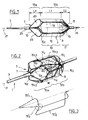
- la figure 1 est une vue en légère perspective d'une portion distale d'un système de protection vasculaire conforme à l'invention, montrant en particulier l'élément filtrant,
- la figure 2 montre la même portion que la figure 1, suivant une perspective proximale,
- la figure 3 est un schéma montrant une autre disposition relative de deux des fils de structure de l'élément filtrant,
- les figures 4, 5, 6, 7, 8, 9, 10 et 11 schématisent à plus petite échelle les principales étapes opératoires de mise en place puis de retrait d'un système de protection vasculaire conforme à l'invention,
- la figure 12 montre avec une perspective légèrement différente la solution de la figure 1, à échelle légèrement réduite, sans membrane et sans guide-fil de commande,
- la figure 13 est une illustration en perspective à la même échelle que la figure 1 d'une solution perfectionnée du dispositif filtrant conforme à l'invention,
- la figure 14 est une vue selon la coupe XIV - XIV de la figure 13,
- et la figure 15 illustre schématiquement en coupe longitudinale un appareil de traitement d'angioplastie équipé du dispositif filtrant de protection distale de l'invention.
- FIG. 1 is a light perspective view of a distal portion of a vascular protection system according to the invention, showing in particular the filter element,
- FIG. 2 shows the same portion as FIG. 1, from a proximal perspective,
- FIG. 3 is a diagram showing another relative arrangement of two of the structural wires of the filter element,
- FIGS. 4, 5, 6, 7, 8, 9, 10 and 11 show diagrammatically on a smaller scale the main operating steps for setting up and then removing a vascular protection system according to the invention,
- FIG. 12 shows with a slightly different perspective the solution of FIG. 1, on a slightly reduced scale, without membrane and without control wire guide,
- FIG. 13 is a perspective illustration on the same scale as FIG. 1 of an improved solution of the filtering device according to the invention,
- FIG. 14 is a view along the section XIV - XIV of FIG. 13,
- and FIG. 15 schematically illustrates in longitudinal section an angioplasty treatment device equipped with the distal protection filter device of the invention.
Intéressons-nous tout d'abord aux figures 1, 2 et 6 pour décrire un
système de protection vasculaire 1 conforme à l'invention.Let’s first look at Figures 1, 2 and 6 to describe a
Le système de protection vasculaire 1 comprend un fil-guide 3 fixé
à un élément filtrant distal 5 comprenant lui-même essentiellement une
structure support 7 radialement auto-expansible, et une membrane filtrante 9
définissant une poche déformable radialement.The
Le fil-guide 3 est soit un fil flexible, tel qu'un fil métallique, soit un
fin cathéter. Sa longueur est suffisante pour atteindre la zone vasculaire à
protéger (comme par exemple la zone 10 de la carotide interne 11 de la figure
6), depuis l'extérieur du corps du patient, c'est-à-dire depuis l'extérieur de la
surface cutanée référencée 13 sur la figure 3.The
Compte tenu du débit de fluide corporel devant passer à travers la
membrane 9, celle-ci est de préférence réalisée avec un film plastique
polymère imperméable, percé localement d'orifices distaux 15 laissant le
passage au fluide corporel. Toutefois, on peut aussi envisager utiliser une
matière poreuse, par exemple en polyuréthane. Un maillage pourrait
éventuellement convenir. Toutefois, il est conseillé que le filtre 9 soit poreux
au fluide corporel (sang en particulier) exclusivement sur sa portion distale
17 sensiblement conique, tandis que le filtre sera sensiblement imperméable
sur sa portion proximale 19 cylindrique, de section essentiellement constante
et sensiblement circulaire.Given the flow of body fluid to pass through the
La feuille (ou membrane) filtrante 9 est liée à la structure support 7
pour son déploiement et son repliement radial, c'est-à-dire essentiellement
perpendiculairement à l'axe général 21 du système de protection vasculaire
(lequel axe est confondu avec l'axe du fil-guide 3). The filter sheet (or membrane) 9 is linked to the
La structure support 7 comprend périphériquement une
succession de fils 70 qui s'étendent globalement parallèlement à l'axe 21 et
qui comprennent un tronçon proximal 70a et un tronçon distal 70b réunis
entre eux par un tronçon intermédiaire 70c transversal à l'axe 21.The
Sur la figure 2, on constate plus nettement que, (sur la périmétrie
de l'élément filtrant) les tronçons intermédiaires transversaux tels que 70c1 et
70c2 de deux fils successifs tels que 701 et 702, présentent entre eux une
extrémité adjacente définie par la zone 71a.In FIG. 2, it can be seen more clearly that, (on the perimeter of the filter element) the transverse intermediate sections such as 70c 1 and 70c 2 of two successive wires such as 70 1 and 70 2 have between them an adjacent end defined by
Dans l'exemple préféré illustré, les tronçons proximaux et distaux
70a et 70b de plusieurs fils successifs sont même sensiblement adjacents, sur
toute leur longueur, avec un décalage angulaire d'un fil, autour de l'axe 21,
entre les dispositions adjacentes des fils le long de leur tronçon proximal et
de leur tronçon distal.In the preferred example illustrated, the proximal and
Ainsi, sur leur tronçon proximal 70a, les fils 701 et 703 sont
parallèles et adjacents, bord à bord, le fil 701 devenant ensuite parallèle et
adjacent, à nouveau bord à bord, avec le fil 702, sur le tronçon distal 70b.
Entre les deux tronçons, le tronçon intermédiaire 70c1 du fil 701 est adjacent,
vers la zone d'extrémité 71b, au tronçon intermédiaire 70c3 du filtre 703,
tandis qu'il est adjacent au tronçon intermédiaire 70c2 du filtre 702 à son autre
extrémité, à l'endroit de la zone de raccordement 71a.Thus, on their
Une telle configuration, répétée sur tout le pourtour de l'élément
filtrant 5, fait que la succession des tronçons intermédiaires des fils (70c1, 70c3
et ainsi de suite) définit une lèvre périmétrique sensiblement continue qui va
favoriser le positionnement de la membrane 9 dont le bord proximal 90
(extrémité proximale) va épouser le contour de cette lèvre ouverte en étant
en appui contre.Such a configuration, repeated over the entire periphery of the
Pour l'ouverture radiale de l'élément filtrant, le tronçon proximal
70a des fils de structure est sensiblement conique, tandis que chaque tronçon
distal 70b des fils est d'abord cylindre de section (sur la longueur axiale L1 du
tronçon 19 de la membrane 9), puis sensiblement conique, sur la longueur
axiale L2 correspondant au tronçon 17 de la membrane.For the radial opening of the filter element, the
Le bord proximal 90 de la membrane et la lèvre ouverte définie
par la succession des tronçons intermédiaires transversaux des fils sont situés
sensiblement à l'endroit de la jonction entre les zones conique et cylindrique
des tronçons de fils 70a, 70b.The
La forme en deux cônes inversés des extrémités proximale et
distale de l'élément filtrant permet aux fils, ou pattes, 70, d'être serrés, côté
proximal, dans une première bague 23 qui assure la liaison entre l'élément
filtrant 5 et le fil-guide 3 et, côté distal, dans une deuxième bague 24 liée à un
embout flexible ("floppy end") 25. A noter que l'on a préféré une telle
disposition des fils avec des portions de fils doublés (hormis à l'endroit des
tronçons intermédiaires de raccordement 70c1, 70c3, ...) plutôt qu'une
disposition des fils tous dans le même sens sur la périphérie de la lèvre
d'ouverture, comme sur la figure 3, avec alors des tronçons qui ne sont pas
doublés (hormis à leurs extrémités proximale et distale, les fils tels que 70'1,
70'2 ne sont adjacents, dans leur état radialement déployé, qu'à une seule
extrémité de leur tronçon intermédiaire, en 71'a). La solution préférée des
figures 1 et 2 favorise les manoeuvres radiales de l'élément filtrant et renforce
l'étanchéité vis-à-vis de la paroi interne du vaisseau.The shape in two inverted cones of the proximal and distal ends of the filter element allows the wires, or tabs, 70, to be tightened, proximal side, in a
Concernant cette étanchéité, il est à noter que si le tronçon 19 est
de section sensiblement constante sur sa longueur L1, l'étanchéité s'en
trouvera d'autant favorisée par rapport aux formes courantes coniques ou
tronconiques depuis l'extrémité proximale d'ouverture de la membrane
jusqu'à l'extrémité distale de l'élément filtrant (comme dans
WO-A-99/23976 ou WO-A-99/44542).Regarding this sealing, it should be noted that if the
De préférence, la longueur L1 sera comprise entre 2 et 4 fois les
longueurs L1 et L3 (L3 étant la longueur axiale du tronçon proximal 70a), L2
et L3 étant telles que L2 ≤ L3 ≤ 1,5 L2, ceci pour optimiser l'étanchéité et les
conditions d'ouverture/fermeture de l'élément filtrant 5.Preferably, the length L 1 will be between 2 and 4 times the lengths L 1 and L 3 (L 3 being the axial length of the
Les fils 70 peuvent être métalliques (acier inoxydable en
particulier ) ou à mémoire de forme thermique ("Nitinol"®, en particulier),
voire en matière synthétique.The
Ils se présentent, côté proximal, de manière à constituer au moins
deux groupes de fils (en l'espèce, quatre) chacun de deux fils tels que 701, 703,
pour un groupe, ou encore, 702, 704, pour un autre groupe, ces fils étant, sur
la longueur L3 adjacents entre eux (en l'espèce, bord à bord et rectilignes). Au
bout de cette longueur L3 qui débute à l'endroit de la bague proximale 15 et
qui s'étend sensiblement jusqu'à la limite de la lèvre d'ouverture 90 de la
membrane, les groupes de fils de scindent.They are presented, on the proximal side, so as to constitute at least two groups of wires (in this case, four) each of two wires such as 70 1 , 70 3 , for a group, or even 70 2 , 70 4 , for another group, these wires being, along the length L 3 adjacent to each other (in this case, edge to edge and straight lines). At the end of this length L 3 which begins at the location of the
Ainsi, par exemple les fils 701, 703 s'écartent l'un de l'autre à
l'endroit de la zone 71b suivant une courbure telle que, peu après sur leur
longueur, ces fils qui se sont écartés se réunissent de façon adjacente à un fil
d'un autre groupe. En l'espèce, on note ainsi que le fil 701 se rapproche du fil
702, les fils 704 et 703 se rapprochant eux-mêmes individuellement d'un fil
d'un groupe non référencé.Thus, for example, the
On notera également que ce rapprochement s'effectue sur la
longueur L1, les fils (tels que 701, et 702) étant, sur cette longueur, parallèle à
l'axe 11, alors que, bien que demeurant essentiellement rectilignes, ils se
développent suivant une corolle conique tant sur la longueur proximale L3
que sur la longueur distale L2 à l'endroit de laquelle se trouve le fond arrondi
de la membrane 9.It will also be noted that this approximation takes place over the length L 1 , the wires (such as 70 1 , and 70 2 ) being, on this length, parallel to the
Pour la fiabilité de la structure support 7 et pour favoriser les
avantages précités, on notera également que les tronçons intermédiaires de
fils 70c1 ... se raccorderont aux tronçons proximaux et distaux des mêmes fils
(tels que 701) par des coudes arrondis présentant un angle intérieur
(respectivement α1 pour le raccordement proximal et α2 pour le
raccordement distal, sur la figure 2) tel que chaque angle (α1, α2) soit compris
entre environ 90° et 135°.For the reliability of the
La lèvre périphérique d'ouverture de la membrane 9, de même
que les tronçons intermédiaires de fils 70c1, 70c2, ... définissent une succession
d'arches adjacentes deux à deux.The peripheral opening lip of the
Avantageusement, la structure filtrante 9 sera disposée à
l'extérieur de la structure support 7, en appui sur le tronçon distal 70b.Advantageously, the
La membrane pourra être collée aux fils de structure.The membrane can be glued to the structural wires.
En liaison avec les figures 4 à 11, on va maintenant présenter une procédure opératoire pour utiliser le système de protection vasculaire temporaire que l'on vient de présenter.In connection with FIGS. 4 to 11, we will now present a operating procedure for using the vascular protection system temporary that we just presented.
Sur la figure 4, on voit en particulier une surface cutanée 13 d'un
corps 27, ainsi qu'une carotide 29 qui se scinde en une carotide externe 31 et
une carotide interne 11.In FIG. 4, we see in particular a
A l'embranchement de la carotide interne 11, on note la présence
d'une sténose 33.At the junction of the internal carotid 11, we note the
Pour traiter cette sténose, tout en protégeant le coeur contre les
emboles, on va utiliser le dispositif de protection vasculaire 1.To treat this stenosis, while protecting the heart against
emboli, we will use the
Pour cela, le praticien introduit tout d'abord à travers la peau 13 et
jusque dans la carotide 29, un cathéter-guide 35 dont l'extrémité proximale
35a ressort du corps du patient.For this, the practitioner first introduces through the
Sur la figure 5, on note qu'à travers le cathéter-guide 35 (et depuis
l'extérieur du corps du patient) a été glissé un cathéter d'introduction 37.In FIG. 5, it is noted that through the guide catheter 35 (and from
outside the patient's body) was inserted an
Dans le cathéter d'introduction 37 (typiquement d'un diamètre
4F), a été mis en place le dispositif de protection vasculaire 1 de l'invention
comprenant l'élément filtrant 5 manoeuvrable par son fil-guide 3 (dont
l'extrémité proximale, non représentée, ressort bien entendu du corps du
patient pour être manoeuvrable depuis l'extérieur de ce corps). In the introducer catheter 37 (typically of a diameter
4F), was implemented the
L'embout distal 25 sert de guide souple et sort à l'extérieur de
l'extrémité distale 37a du cathéter 37.The
Dans cet état, l'élément filtrant 5 est rétracté, contraint radialement
par le cathéter 37 qui l'entoure en le comprimant radialement.In this state, the
A la sortie du cathéter-guide 35, le praticien fait franchir au
cathéter 37 la sténose 33 pour amener son extrémité distale 37a en aval, dans
la carotide interne 11. Le sens du flux sanguin est schématisé par la flèche 39.At the exit of the
Sur la figure 6, le cathéter d'introduction 37 a été tiré vers l'arrière,
tandis qu'on a maintenu en place l'élément filtrant radialement auto-expansible
5, ce qui fait que ce dernier est sorti du cathéter et s'est
radialement ouvert dans une position comparable à celle des figures 1 et 2.In FIG. 6, the
L'élément filtrant, ou filtre temporaire, 5, s'est ainsi plaqué contre
la paroi intérieure 11a de la carotide 11 vis-à-vis de laquelle il y a maintenant
étanchéité.The filter element, or temporary filter, 5, is thus pressed against
the
Le cathéter d'introduction 37 est ensuite retiré à travers le
cathéter-guide 35 (voir figure 7). Le filtre 5 protège la zone vasculaire 10,
ainsi que toute la suite du vaisseau, au-delà.The
Pour réduire la sténose 33, le praticien peut alors introduire à
travers toujours la même voie d'accès comprenant le cathéter-guide 35, un
cathéter 39 à ballonnet dégonflé 41.To reduce
Le ballonnet, dans son état dégonflé, est placé à l'endroit de la
sténose 33. On gonfle alors le ballonnet ce qui produit une dilatation de la
sténose, comme on le voit sur la figure 8.The balloon, in its deflated state, is placed at the location of the
Après dilatation, le ballonnet 41 est dégonflé et retiré avec le
cathéter 39 (à nouveau à travers le cathéter-guide 35).After expansion, the
Bien entendu, le ballonnet 41 est fixé au cathéter 39 et un passage à
travers le cathéter 39 permet au fluide de gonflage d'arriver vers le, et de
repartir du, ballonnet. Of course, the
La dilatation de la sténose risque de provoquer le détachement de
débris vasculaires et de créer des emboles, y compris après retrait du
ballonnet. L'élément filtrant 5 est là pour les retenir.The dilation of the stenosis may cause detachment of
vascular debris and create emboli, including after removal of the
balloon. The
Après avoir retiré le cathéter à ballonnet, le praticien introduit,
toujours à travers le cathéter-guide 35, un cathéter 43 d'introduction d'un
implant radialement expansible, couramment dénommé "stent".After removing the balloon catheter, the practitioner introduces,
still through the
Pour son introduction, le stent est, à l'image de l'élément filtrant 5
sur la figure 5, conditionné dans un état radialement resserré à l'intérieur du
cathéter 43.For its introduction, the stent is, like the
Après avoir placé l'extrémité distale 43a du cathéter 43 au niveau
de la sténose écrasée 33', le cathéter 43 est tiré vers l'arrière, tandis qu'un
poussoir (non représenté) permet au stent de sortir du cathéter 43 et de se
déployer radialement (s'il est auto-expansible comme le stent
schématiquement représenté en 45 sur la figure 9) ou d'être radialement
déformé par l'intermédiaire d'un ballonnet interne gonflable (solution non
représentée).After placing the distal end 43a of the
Quoi qu'il en soit, le stent est radialement déployé à l'endroit de la sténose 33' de manière que le passage vasculaire reste ouvert.Anyway, the stent is radially deployed at the location of the stenosis 33 'so that the vascular passage remains open.
Le cathéter 43 est retiré à travers le cathéter-guide 35.The
Depuis qu'il est en place, le filtre temporaire 5 a récupéré des
débris vasculaires 47, sans empêcher le sang de circuler dans la carotide
interne 11 (voir la flèche sur la figure 9).Since it is in place, the
Avec le sang, les débris vasculaires 47 vont pénétrer et se sont
accumulés à l'intérieur de la membrane 9, via les ouvertures d'accès 49
ménagées entre les branches 70, côté proximal 70a (voir figure 1).With blood, vascular debris 47 will penetrate and have
accumulated inside the
Le sang a pu librement ressortir par les orifices distaux 15 dont la
section est inférieure à celle des débris vasculaires qui sont ainsi piégés dans
le filtre 5, par sa membrane. The blood was able to flow freely through the
Typiquement, la section des orifices d'entrée est égale ou supérieure à 0,5 mm2, voire de l'ordre de 0,2 à 0,3 cm2, tandis que la section de chaque orifice 15 de sortie du sang peut être inférieure à 0,1 mm2.Typically, the section of the inlet orifices is equal to or greater than 0.5 mm 2 , or even of the order of 0.2 to 0.3 cm 2 , while the section of each blood outlet orifice can be less than 0.1 mm 2 .
Une fois que le praticien juge les risques de migration des débris
vers le coeur comme suffisamment limités, un cathéter 49 de retrait est
introduit à travers le cathéter-guide 35 jusqu'au-delà du stent 45 et l'élément
filtrant 5 (contenant les débris vasculaires 47) est tiré à l'intérieur du cathéter
49 par son fil-guide 3, et retiré comme on le voit sur la figure 10.Once the practitioner judges the risks of debris migration
towards the heart as sufficiently limited, a
Le cathéter 49 contenant le système de protection vasculaire distal
1 est alors lui-même retiré, permettant ainsi aux débris vasculaires d'être
extraits du corps du patient.
On notera que depuis le retrait du cathéter d'introduction 37
(figure 6), le fil-guide 3 du système de protection vasculaire 1 a permis aux
différents cathéters 39, 43, ... d'être guidés jusqu'à leur zone de mise en place.Note that since the withdrawal of the introducer catheter 37
(Figure 6), the
En fin d'intervention, le cathéter-guide 35 (de plus gros diamètre
que les autres cathéters) est retiré du corps du patient et la voie d'accès à
l'endroit de la peau 13 est fermée.At the end of the intervention, the guide catheter 35 (of larger diameter
than other catheters) is removed from the patient's body and the path to
the place of the
Seul le stent 45 est laissé en place.Only the
L'utilisation du système de protection vasculaire de l'invention, dans le cadre de la procédure d'intervention qui vient d'être présentée permet au praticien d'assurer une filtration temporaire du sang limitant nettement les risques d'embolie.The use of the vascular protection system of the invention, as part of the intervention procedure which has just been presented allows the practitioner to ensure a temporary filtration of the limiting blood clearly the risks of embolism.
Intéressons-nous maintenant à la variante de la figure 12 pour constater :
- que les longueurs axiales L1, L2, L3 sont comparables,
- que, dans l'état radialement expansé du dispositif 1, les tronçons successifs conique (22) puis cylindrique (24) des fils se raccordent par des tronçons filamentaires en "S" tels que le tronçon 70c1, ces tronçons intermédiaires de raccordement constituant la seule partie des fils où ceux-ci sont unitaires et non pas groupés au moins par deux, bord à bord,
- et que des bagues intermédiaires telles que 26 qui sont
interposées d'endroits en endroits entre les bagues d'extrémité 23'
et 23".
- that the axial lengths L 1 , L 2 , L 3 are comparable,
- that, in the radially expanded state of the
device 1, the successive conical (22) then cylindrical (24) sections of the wires are connected by filamentary "S" sections such as thesection 70 c1 , these intermediate connecting sections constituting the single part of the wires where these are unitary and not grouped at least in pairs, edge to edge, - and that intermediate rings such as 26 which are interposed from place to place between the end rings 23 'and 23 ".
Les bagues 26 ont pour objet de maintenir les fils réunis entre eux,
bord à bord sur la longueur où ils doivent l'être et servent également de
repères radio-opaques.The purpose of the
Les bagues peuvent donc être en particulier métalliques.The rings can therefore be in particular metallic.
Les bagues entourent les fils alors placés bord à bord et c'est à travers des ouvertures telles que 28 ménagées à travers la paroi des bagues que l'on soude entre eux les fils ainsi réunis (voir points de soudure 30). Cette technique limite les contraintes supportées par les fils (qui sont donc non seulement soudés deux à deux mais maintenus serrés par les bagues) avec un effet de radio-opacité très favorable.The rings surround the wires then placed edge to edge and it is at through openings such as 28 made through the wall of the rings that the wires thus joined together are welded together (see soldering points 30). This technique limits the stresses borne by the wires (which are therefore not only welded two by two but kept tight by the rings) with a very favorable radiopacity effect.
Les figures 13 et 14 illustrent un autre élément filtrant 10 conforme
à l'invention utilisable comme dispositif de protection distal.Figures 13 and 14 illustrate another conforming
Sur la figure 13, partant de la bague proximale 23', s'étendent deux
groupes proximaux 32, 34 de chacun quatre fils appartenant à la structure
radialement expansible de l'élément filtrant 10.In FIG. 13, starting from the
Par groupe, les fils sont parallèles entre eux, adjacents et en
l'espèce rectilignes. Ils s'étendent suivant des génératrices du cône proximal
que définit là la structure. A l'endroit du diamètre D maximal d'expansion
radiale de la structure, ou bien à proximité de ce diamètre, certains fils de
chaque groupe s'écartent des autres fils du même groupe pour aller se
raccorder à des fils de l'autre groupe, un plus loin sur la longueur, là où la
structure est déjà cylindrique (longueur L'1). A ce sujet, pour un diamètre D
de la structure 10 dans son état radialement ouvert, la longueur L'1 sera telle
que L'1 > 1,5 D, L'1 étant la longueur de la partie sensiblement cylindrique de
la structure dans cet état. By group, the wires are parallel to each other, adjacent and in this case rectilinear. They extend along generatrices of the proximal cone which the structure defines there. At the place of the maximum diameter D of radial expansion of the structure, or indeed near this diameter, certain wires of each group move away from the other wires of the same group to go and connect to wires of the other group , one further along the length, where the structure is already cylindrical (length L ' 1 ). On this subject, for a diameter D of the
Dans l'exemple illustré, la position angulaire des fils ne va alors
plus changer jusqu'à la bague distale 23", c'est-à-dire que les fils (en l'espèce
donc réunis par paires) vont rester parallèles et adjacents deux à deux sur
toute la longueur restante du tronçon cylindrique (longueur L'1) puis sur la
partie conique distale (longueur L'2).In the example illustrated, the angular position of the wires will then no longer change up to the
Notamment pour les fils élastiques 70'1 et 70'2, on retrouve bien la
forme "en S" sur leur tronçon (70'c1 ou 70'c2) de liaison entre les zones de
regroupement respectivement proximal (groupe 34) et plus distal que l'on
avait déjà noté sur la figure 1.In particular for
A l'endroit de ce tronçon intermédiaire incurvé où les fils concernés présentent une composante radiale, lesdits fils tels que 70'1 et 70'2 sont seuls. C'est à cet endroit que la membrane étanche (au liquide, en particulier au sang) repérée en traits mixtes 9' se termine, à son extrémité proximale ouverte 90', ladite membrane étant par contre fermée à son extrémité distale opposée, à l'endroit de sa paroi de fond 19', là où sont situées les ouvertures 15' de sortie de sang.At the location of this curved intermediate section where the wires concerned have a radial component, said wires such as 70 ′ 1 and 70 ′ 2 are alone. It is at this point that the waterproof membrane (liquid, in particular blood) marked in dashed lines 9 'ends, at its open proximal end 90', said membrane being closed on the other hand at its opposite distal end, 'location of its bottom wall 19', where the openings 15 'for blood outlet are located.
Sur la figure 13, on constate en outre qu'à l'endroit où les groupes
de fils se scindent (comme par exemple à l'endroit de la bague 26a pour le
groupe de fils 34), deux des quatre fils s'écartent (fils 70'1 et 70'2), tandis que
les deux autres restent réunis de façon adjacente (70'3 et 70'4,) et le
demeurent, en l'espèce sur toute leur longueur restante, c'est-à-dire qu'ils
demeurent parallèles et l'un contre l'autre jusqu'à la bague distale 23".In FIG. 13, it can also be seen that at the place where the groups of wires split (as for example at the location of the
Comme dans le cas de la structure antérieure de la figure 1, le fil 70'1 va rejoindre le fil 70'5 de l'autre groupe, de même pour le fil 70'2 qui va rejoindre le fil 70'6 du second groupe avec, à chaque fois donc, un décalage angulaire pour passer d'un groupe à l'autre, c'est-à-dire une composante radiale à l'endroit des zones telles que 70'c1 et 70'c2.As in the case of the previous structure of FIG. 1, the wire 70 ' 1 will join the wire 70' 5 of the other group, the same for the wire 70 ' 2 which will join the wire 70' 6 of the second group with, each time therefore, an angular offset to move from one group to another, that is to say a radial component at the location of areas such as 70 ′ c1 and 70 ′ c2 .
Ainsi, deux larges ouvertures 36, 38 pourront être définies côté
proximal de la structure 10, les deux ouvertures étant séparées l'une de
l'autre par les groupes proximaux 32, 34 de fils, ceci jusqu'aux bagues 26a,
26b où débutent les tronçons intermédiaires de liaison à composante radiale
"en S", tels que 70'c1 et 70'c2.Thus, two
Autant les bagues proximale et distale 23', 23", serrent et
maintiennent axialement les extrémités respectives des fils élastiques (comme
on peut le voir notamment sur la figure 14), autant les bagues intermédiaires
radio-opaques telles que 26a, 26b, maintiennent les fils dans leurs positions
précitées à la manière de ce qui a déjà été décrit pour les bagues 26 de la
figure 12.Both the proximal and
Sur cette figure 14, on voit également nettement les deux grandes
ouvertures 36, 38, ainsi que la forme à composante radiale des tronçons
périphériques intermédiaires de liaison tels que 70'c1 et 70'c2.This FIG. 14 also clearly shows the two
De préférence, les bagues radio-opaques 26 marqueront le début
et la fin du tronçon cylindre de longueur L'1.Preferably, the radio-
Dans l'état radialement resserré de la structure 10, les fils
élastiques s'ils sont auto-expansibles, sont déformés et contraints pour
s'étendre essentiellement parallèlement à l'axe 21' (hormis les tronçons de
raccordement tels que 70'c1 et 70'c2), les tronçons reprenant leur forme
naturelle arquée radialement déployée dès leur libération.In the radially tightened state of the
Au lieu de cela, on aurait pu imaginer utiliser une tirette, voire un
autre moyen d'expansion, pour rapprocher ou écarter axialement l'une de
l'autre les deux bagues 23', 23", mécaniquement.Instead, you could have imagined using a zipper or even a
other means of expansion, to bring one axially closer or apart
the other the two
A noter qu'au lieu de groupes proximaux tels que 34 de quatre fils, on aurait par exemple pu prévoir au moins deux groupes de trois fils chacun, les fils de chaque groupe se séparant les uns des autres avant, pour deux des fils de chacun de ces groupes, de se réunir de nouveau avec un fil de l'autre groupe, le troisième fil demeurant seul sur le reste de la longueur de la structure, jusqu'à la bague distale 23". Note that instead of proximal groups such as 34 of four wires, for example, we could have planned at least two groups of three sons each, the sons of each group separating from each other before, for two of the sons of each of these groups, to reunite again with a thread of the other group, the third wire remaining alone over the rest of the length of the structure, up to the 23 "distal ring.
Dans cette hypothèse, on aurait donc, sur la portion cylindrique de longueur L'1, deux groupes de deux fils diamétralement opposés, ainsi que deux groupes d'un seul fil également diamétralement opposés, alors que sur la figure 13, on voit quatre groupes chacun de deux fils tant sur la longueur L'1 que sur la longueur L'2.In this hypothesis, we would therefore have, on the cylindrical portion of length L ' 1 , two groups of two diametrically opposite wires, as well as two groups of a single wire also diametrically opposite, whereas in FIG. 13, we see four groups each of two wires both on the length L ' 1 and on the length L' 2 .
Sur la figure 14, on peut d'ailleurs constater cette répartition angulaire.In Figure 14, we can also see this distribution angular.
Sur la figure 15, le dispositif de filtration 10 appartient à un
appareil d'angioplastie 20.In FIG. 15, the
Plus généralement, le dispositif 10 au bout de son fil-guide 3 (qui
est en l'espèce un cathéter) peut en particulier être utilisé comme dispositif
de protection distale d'un appareillage de traitement vasculaire risquant de
placer dans le flux sanguin des matériaux emboliques dont la migration vers
le coeur ou le cerveau peut s'avérer dangereuse.More generally, the
La structure filtrante 10 se trouve en aval par rapport à la zone
d'intervention constituée par la sténose 89 sur la figure 15 (le sens du flux
sanguin ayant été repéré par la flèche 91). Elle va donc permettre de filtrer ce
sang en retenant les particules emboliques (orifices 15' de section inférieure à
la taille de ces matières), sans interrompre pour autant substantiellement la
circulation sanguine. On notera que la caractéristique L1 (ou L'1) > 1,5 D
favorise l'étanchéité, le centrage et l'efficacité de la structure filtrante.The
L'appareil 20 comprend un ballon 93 qui peut être radialement
gonflé par l'intermédiaire du cathéter 3 auquel il est fixé.The
Tant le ballon 93 que le dispositif filtrant 10 sont adaptés pour être
radialement contenus, pour leur introduction vasculaire, dans une gaine
d'introduction/retrait 95 adaptée pour passer à travers le corps du patient
jusqu'à la zone vasculaire concernée.Both the
Les longueurs respectives de la gaine 95 et du moyen de
manoeuvre (cathéter 3) sont au moins égales à la distance séparant la zone
d'intervention vasculaire (zone de la sténose) de la surface cutanée du corps
du patient à partir de laquelle le dispositif d'intervention est implanté par
voie endoluminale.The respective lengths of the
S'il est auto-expansible, le dispositif filtrant 10 s'expanse
radialement dès sa sortie de la gaine 95. De toute façon, la structure du
dispositif 10 est radialement expansible mécaniquement.If it is self-expanding, the
Le ballon 93, qui peut être un ballon d'angioplastie, est gonflé avec
un fluide qui circule soit à travers le cathéter 3, soit à travers un tube séparé
(non représenté) auquel il serait alors fixé.
Sur la figure 15, l'expansion radiale du ballon 93 a élargi le
vaisseau 97 à l'endroit de la sténose 89 face à laquelle le ballon a été disposé.In FIG. 15, the radial expansion of the
Préalablement (ou de façon simultanée), la structure filtrante 10 a été radialement déployée pour obturer le vaisseau en aval de l'emplacement de la sténose et du ballon.Beforehand (or simultaneously), the filtering structure 10 a been radially deployed to seal the vessel downstream of the location stenosis and balloon.
Plaquer le ballon contre la paroi du vaisseau crée typiquement le détachement de matériaux emboliques tels que 99 qui ont tendance à migrer en aval, emportés par le flux.Placing the balloon against the vessel wall typically creates the detachment of embolic materials such as 99 which tend to migrate downstream, carried away by the flow.
Leur migration est bloquée par le dispositif filtrant 10.Their migration is blocked by the
Claims (13)
Applications Claiming Priority (4)
| Application Number | Priority Date | Filing Date | Title |
|---|---|---|---|
| FR0109427A FR2827152B1 (en) | 2001-07-13 | 2001-07-13 | DOUBLE-BRANCH VASCULAR PROTECTION SYSTEM |
| FR0109427 | 2001-07-13 | ||
| FR0113815A FR2831422B3 (en) | 2001-10-25 | 2001-10-25 | VASCULAR PROTECTION SYSTEM WITH LARGE INPUT OPENINGS AND ANGIOPLASTY APPARATUS THUS EQUIPPED |
| FR0113815 | 2001-10-25 |
Publications (2)
| Publication Number | Publication Date |
|---|---|
| EP1277448A1 true EP1277448A1 (en) | 2003-01-22 |
| EP1277448B1 EP1277448B1 (en) | 2006-06-07 |
Family
ID=26213096
Family Applications (1)
| Application Number | Title | Priority Date | Filing Date |
|---|---|---|---|
| EP02291634A Expired - Fee Related EP1277448B1 (en) | 2001-07-13 | 2002-07-01 | System of vascular protection and angioplasty device |
Country Status (4)
| Country | Link |
|---|---|
| US (1) | US6932831B2 (en) |
| EP (1) | EP1277448B1 (en) |
| DE (1) | DE60212006T2 (en) |
| ES (1) | ES2264468T3 (en) |
Cited By (2)
| Publication number | Priority date | Publication date | Assignee | Title |
|---|---|---|---|---|
| EP1604702A1 (en) * | 2004-06-08 | 2005-12-14 | Sango S.A.S | A vascular guidewire for venous valvular angioplasty |
| US7927349B2 (en) | 2001-12-21 | 2011-04-19 | Salviac Limited | Support frame for an embolic protection device |
Families Citing this family (129)
| Publication number | Priority date | Publication date | Assignee | Title |
|---|---|---|---|---|
| DE69838952T2 (en) * | 1997-11-07 | 2009-01-02 | Salviac Ltd. | EMBOLISM PROTECTION DEVICE |
| US7491216B2 (en) | 1997-11-07 | 2009-02-17 | Salviac Limited | Filter element with retractable guidewire tip |
| US6964672B2 (en) * | 1999-05-07 | 2005-11-15 | Salviac Limited | Support frame for an embolic protection device |
| WO2000067670A1 (en) * | 1999-05-07 | 2000-11-16 | Salviac Limited | An embolic protection device |
| WO2000067666A1 (en) * | 1999-05-07 | 2000-11-16 | Salviac Limited | Improved filter element for embolic protection device |
| US6918921B2 (en) * | 1999-05-07 | 2005-07-19 | Salviac Limited | Support frame for an embolic protection device |
| US6660021B1 (en) * | 1999-12-23 | 2003-12-09 | Advanced Cardiovascular Systems, Inc. | Intravascular device and system |
| US6402771B1 (en) | 1999-12-23 | 2002-06-11 | Guidant Endovascular Solutions | Snare |
| US6575997B1 (en) * | 1999-12-23 | 2003-06-10 | Endovascular Technologies, Inc. | Embolic basket |
| US6695813B1 (en) | 1999-12-30 | 2004-02-24 | Advanced Cardiovascular Systems, Inc. | Embolic protection devices |
| US6540722B1 (en) * | 1999-12-30 | 2003-04-01 | Advanced Cardiovascular Systems, Inc. | Embolic protection devices |
| US7918820B2 (en) * | 1999-12-30 | 2011-04-05 | Advanced Cardiovascular Systems, Inc. | Device for, and method of, blocking emboli in vessels such as blood arteries |
| US20040167567A1 (en) * | 2001-03-23 | 2004-08-26 | Cano Gerald G. | Method and apparatus for capturing objects beyond an operative site in medical procedures |
| GB2369575A (en) * | 2000-04-20 | 2002-06-05 | Salviac Ltd | An embolic protection system |
| US6939362B2 (en) * | 2001-11-27 | 2005-09-06 | Advanced Cardiovascular Systems, Inc. | Offset proximal cage for embolic filtering devices |
| US6964670B1 (en) * | 2000-07-13 | 2005-11-15 | Advanced Cardiovascular Systems, Inc. | Embolic protection guide wire |
| US6537294B1 (en) * | 2000-10-17 | 2003-03-25 | Advanced Cardiovascular Systems, Inc. | Delivery systems for embolic filter devices |
| US6893451B2 (en) * | 2000-11-09 | 2005-05-17 | Advanced Cardiovascular Systems, Inc. | Apparatus for capturing objects beyond an operative site utilizing a capture device delivered on a medical guide wire |
| US6506203B1 (en) * | 2000-12-19 | 2003-01-14 | Advanced Cardiovascular Systems, Inc. | Low profile sheathless embolic protection system |
| US6645223B2 (en) * | 2001-04-30 | 2003-11-11 | Advanced Cardiovascular Systems, Inc. | Deployment and recovery control systems for embolic protection devices |
| US6929652B1 (en) * | 2001-06-01 | 2005-08-16 | Advanced Cardiovascular Systems, Inc. | Delivery and recovery systems having steerability and rapid exchange operating modes for embolic protection systems |
| US6793665B2 (en) * | 2001-06-18 | 2004-09-21 | Rex Medical, L.P. | Multiple access vein filter |
| US8282668B2 (en) * | 2001-06-18 | 2012-10-09 | Rex Medical, L.P. | Vein filter |
| US6623506B2 (en) * | 2001-06-18 | 2003-09-23 | Rex Medical, L.P | Vein filter |
| US7179275B2 (en) * | 2001-06-18 | 2007-02-20 | Rex Medical, L.P. | Vein filter |
| CA2455349C (en) | 2001-06-18 | 2011-02-15 | Rex Medical, L.P. | Vein filter |
| US7338510B2 (en) * | 2001-06-29 | 2008-03-04 | Advanced Cardiovascular Systems, Inc. | Variable thickness embolic filtering devices and method of manufacturing the same |
| US6599307B1 (en) * | 2001-06-29 | 2003-07-29 | Advanced Cardiovascular Systems, Inc. | Filter device for embolic protection systems |
| US20030032941A1 (en) * | 2001-08-13 | 2003-02-13 | Boyle William J. | Convertible delivery systems for medical devices |
| US6638294B1 (en) | 2001-08-30 | 2003-10-28 | Advanced Cardiovascular Systems, Inc. | Self furling umbrella frame for carotid filter |
| US6592606B2 (en) | 2001-08-31 | 2003-07-15 | Advanced Cardiovascular Systems, Inc. | Hinged short cage for an embolic protection device |
| US8262689B2 (en) * | 2001-09-28 | 2012-09-11 | Advanced Cardiovascular Systems, Inc. | Embolic filtering devices |
| US7241304B2 (en) | 2001-12-21 | 2007-07-10 | Advanced Cardiovascular Systems, Inc. | Flexible and conformable embolic filtering devices |
| ATE369088T1 (en) * | 2002-03-05 | 2007-08-15 | Salviac Ltd | SYSTEM FOR PROTECTION AGAINST EMBOLIA |
| US6887258B2 (en) * | 2002-06-26 | 2005-05-03 | Advanced Cardiovascular Systems, Inc. | Embolic filtering devices for bifurcated vessels |
| US7172614B2 (en) * | 2002-06-27 | 2007-02-06 | Advanced Cardiovascular Systems, Inc. | Support structures for embolic filtering devices |
| EP1539031B1 (en) * | 2002-09-19 | 2013-01-02 | Memory Metal Holland BV | Vascular filter with improved strength and flexibility |
| US20040064099A1 (en) * | 2002-09-30 | 2004-04-01 | Chiu Jessica G. | Intraluminal needle injection substance delivery system with filtering capability |
| US7252675B2 (en) * | 2002-09-30 | 2007-08-07 | Advanced Cardiovascular, Inc. | Embolic filtering devices |
| US7331973B2 (en) * | 2002-09-30 | 2008-02-19 | Avdanced Cardiovascular Systems, Inc. | Guide wire with embolic filtering attachment |
| US20040088000A1 (en) * | 2002-10-31 | 2004-05-06 | Muller Paul F. | Single-wire expandable cages for embolic filtering devices |
| US20040172055A1 (en) * | 2003-02-27 | 2004-09-02 | Huter Scott J. | Embolic filtering devices |
| US8591540B2 (en) * | 2003-02-27 | 2013-11-26 | Abbott Cardiovascular Systems Inc. | Embolic filtering devices |
| US7892251B1 (en) | 2003-11-12 | 2011-02-22 | Advanced Cardiovascular Systems, Inc. | Component for delivering and locking a medical device to a guide wire |
| US8500774B2 (en) | 2004-01-22 | 2013-08-06 | Rex Medical, L.P. | Vein filter |
| US7976562B2 (en) | 2004-01-22 | 2011-07-12 | Rex Medical, L.P. | Method of removing a vein filter |
| US8162972B2 (en) | 2004-01-22 | 2012-04-24 | Rex Medical, Lp | Vein filter |
| US8062326B2 (en) | 2004-01-22 | 2011-11-22 | Rex Medical, L.P. | Vein filter |
| US9510929B2 (en) | 2004-01-22 | 2016-12-06 | Argon Medical Devices, Inc. | Vein filter |
| US20110208233A1 (en) * | 2004-01-22 | 2011-08-25 | Mcguckin Jr James F | Device for preventing clot migration from left atrial appendage |
| US8211140B2 (en) | 2004-01-22 | 2012-07-03 | Rex Medical, L.P. | Vein filter |
| US7704266B2 (en) | 2004-01-22 | 2010-04-27 | Rex Medical, L.P. | Vein filter |
| US7338512B2 (en) * | 2004-01-22 | 2008-03-04 | Rex Medical, L.P. | Vein filter |
| US7678129B1 (en) | 2004-03-19 | 2010-03-16 | Advanced Cardiovascular Systems, Inc. | Locking component for an embolic filter assembly |
| US8353926B2 (en) * | 2004-04-15 | 2013-01-15 | Cordis Corporation | Long-term retrievable medical filter |
| US20060041271A1 (en) * | 2004-08-20 | 2006-02-23 | Gjalt Bosma | Vascular filter with sleeve |
| CA2844155A1 (en) * | 2004-09-27 | 2006-04-06 | Rex Medical, L.P. | Vein filter |
| WO2006042114A1 (en) * | 2004-10-06 | 2006-04-20 | Cook, Inc. | Emboli capturing device having a coil and method for capturing emboli |
| US8221446B2 (en) * | 2005-03-15 | 2012-07-17 | Cook Medical Technologies | Embolic protection device |
| US8945169B2 (en) | 2005-03-15 | 2015-02-03 | Cook Medical Technologies Llc | Embolic protection device |
| US9259305B2 (en) | 2005-03-31 | 2016-02-16 | Abbott Cardiovascular Systems Inc. | Guide wire locking mechanism for rapid exchange and other catheter systems |
| US20060259132A1 (en) * | 2005-05-02 | 2006-11-16 | Cook Incorporated | Vascular stent for embolic protection |
| US7850708B2 (en) | 2005-06-20 | 2010-12-14 | Cook Incorporated | Embolic protection device having a reticulated body with staggered struts |
| US8109962B2 (en) | 2005-06-20 | 2012-02-07 | Cook Medical Technologies Llc | Retrievable device having a reticulation portion with staggered struts |
| US7766934B2 (en) * | 2005-07-12 | 2010-08-03 | Cook Incorporated | Embolic protection device with an integral basket and bag |
| US7771452B2 (en) * | 2005-07-12 | 2010-08-10 | Cook Incorporated | Embolic protection device with a filter bag that disengages from a basket |
| US8187298B2 (en) * | 2005-08-04 | 2012-05-29 | Cook Medical Technologies Llc | Embolic protection device having inflatable frame |
| US8377092B2 (en) | 2005-09-16 | 2013-02-19 | Cook Medical Technologies Llc | Embolic protection device |
| US8632562B2 (en) * | 2005-10-03 | 2014-01-21 | Cook Medical Technologies Llc | Embolic protection device |
| US8182508B2 (en) * | 2005-10-04 | 2012-05-22 | Cook Medical Technologies Llc | Embolic protection device |
| US20070088382A1 (en) * | 2005-10-13 | 2007-04-19 | Bei Nianjiong J | Embolic protection recovery catheter assembly |
| US8252017B2 (en) * | 2005-10-18 | 2012-08-28 | Cook Medical Technologies Llc | Invertible filter for embolic protection |
| US20070100372A1 (en) * | 2005-11-02 | 2007-05-03 | Cook Incorporated | Embolic protection device having a filter |
| US8216269B2 (en) | 2005-11-02 | 2012-07-10 | Cook Medical Technologies Llc | Embolic protection device having reduced profile |
| US8152831B2 (en) * | 2005-11-17 | 2012-04-10 | Cook Medical Technologies Llc | Foam embolic protection device |
| EP1986568B1 (en) | 2006-02-03 | 2017-04-05 | Covidien LP | Methods and devices for restoring blood flow within blocked vasculature |
| US10076401B2 (en) | 2006-08-29 | 2018-09-18 | Argon Medical Devices, Inc. | Vein filter |
| US20080071307A1 (en) | 2006-09-19 | 2008-03-20 | Cook Incorporated | Apparatus and methods for in situ embolic protection |
| US9901434B2 (en) | 2007-02-27 | 2018-02-27 | Cook Medical Technologies Llc | Embolic protection device including a Z-stent waist band |
| US10076346B2 (en) | 2007-04-17 | 2018-09-18 | Covidien Lp | Complex wire formed devices |
| US11202646B2 (en) | 2007-04-17 | 2021-12-21 | Covidien Lp | Articulating retrieval devices |
| US10064635B2 (en) | 2007-04-17 | 2018-09-04 | Covidien Lp | Articulating retrieval devices |
| US8535334B2 (en) | 2007-04-17 | 2013-09-17 | Lazarus Effect, Inc. | Complex wire formed devices |
| WO2008153653A1 (en) * | 2007-05-31 | 2008-12-18 | Rex Medical, L.P. | Fallopian tube occlusion device |
| US8216209B2 (en) | 2007-05-31 | 2012-07-10 | Abbott Cardiovascular Systems Inc. | Method and apparatus for delivering an agent to a kidney |
| US7867273B2 (en) | 2007-06-27 | 2011-01-11 | Abbott Laboratories | Endoprostheses for peripheral arteries and other body vessels |
| US8795318B2 (en) | 2007-09-07 | 2014-08-05 | Merit Medical Systems, Inc. | Percutaneous retrievable vascular filter |
| WO2009032834A1 (en) | 2007-09-07 | 2009-03-12 | Crusader Medical Llc | Percutaneous permanent retrievable vascular filter |
| US8252018B2 (en) * | 2007-09-14 | 2012-08-28 | Cook Medical Technologies Llc | Helical embolic protection device |
| US9138307B2 (en) | 2007-09-14 | 2015-09-22 | Cook Medical Technologies Llc | Expandable device for treatment of a stricture in a body vessel |
| US8419748B2 (en) * | 2007-09-14 | 2013-04-16 | Cook Medical Technologies Llc | Helical thrombus removal device |
| EP2211765B1 (en) | 2007-11-02 | 2024-04-17 | Argon Medical Devices, Inc. | Vein filter |
| WO2009073553A1 (en) * | 2007-11-30 | 2009-06-11 | Cook Incorporated | Method and device for vascular therapy |
| JP5385302B2 (en) | 2007-12-26 | 2014-01-08 | ラザラス エフェクト, インコーポレイテッド | Recovery system and method of use |
| US8388644B2 (en) * | 2008-12-29 | 2013-03-05 | Cook Medical Technologies Llc | Embolic protection device and method of use |
| US20100211094A1 (en) * | 2009-02-18 | 2010-08-19 | Cook Incorporated | Umbrella distal embolic protection device |
| EP2403583B1 (en) | 2009-03-06 | 2016-10-19 | Lazarus Effect, Inc. | Retrieval systems |
| US20100274277A1 (en) * | 2009-04-27 | 2010-10-28 | Cook Incorporated | Embolic protection device with maximized flow-through |
| WO2011091383A1 (en) | 2010-01-22 | 2011-07-28 | Lazarus Effect, Inc. | Retrieval systems and methods for use thereof |
| WO2012009675A2 (en) | 2010-07-15 | 2012-01-19 | Lazarus Effect, Inc. | Retrieval systems and methods for use thereof |
| WO2012023980A1 (en) | 2010-08-17 | 2012-02-23 | St. Jude Medical, Inc. | Sleeve for facilitating movement of a transfemoral catheter |
| BR112013006302A2 (en) | 2010-09-17 | 2016-06-07 | St Jude Medical Cardiology Div | placement device for a collapsible prosthetic heart valve, and method for placing a collapsible prosthetic heart valve |
| SG2014013320A (en) | 2011-05-23 | 2014-07-30 | Lazarus Effect Inc | Retrieval systems and methods for use thereof |
| EP2736450A1 (en) | 2011-07-28 | 2014-06-04 | St. Jude Medical, Inc. | Expandable radiopaque marker for transcatheter aortic valve implantation |
| US8740931B2 (en) | 2011-08-05 | 2014-06-03 | Merit Medical Systems, Inc. | Vascular filter |
| US8734480B2 (en) | 2011-08-05 | 2014-05-27 | Merit Medical Systems, Inc. | Vascular filter |
| JP5998147B2 (en) * | 2011-09-27 | 2016-09-28 | 寛治 井上 | Vascular free substance capture device |
| US10143452B2 (en) * | 2011-12-05 | 2018-12-04 | Pi-Cardia Ltd. | Fracturing calcifications in heart valves |
| US9452039B2 (en) | 2012-02-23 | 2016-09-27 | Merit Medical Systems, Inc. | Vascular filter |
| US9480561B2 (en) | 2012-06-26 | 2016-11-01 | St. Jude Medical, Cardiology Division, Inc. | Apparatus and method for aortic protection and TAVI planar alignment |
| US9918837B2 (en) | 2012-06-29 | 2018-03-20 | St. Jude Medical, Cardiology Division, Inc. | System to assist in the release of a collapsible stent from a delivery device |
| US10959715B2 (en) | 2012-10-31 | 2021-03-30 | W. L. Gore & Associates, Inc. | Devices and methods related to deposited support structures |
| US10675012B2 (en) | 2012-11-16 | 2020-06-09 | W. L. Gore & Associates, Inc. | Joint assembly for medical devices |
| US11744594B2 (en) | 2012-11-16 | 2023-09-05 | W.L. Gore & Associates, Inc. | Space filling devices |
| EP3030194B1 (en) | 2013-08-09 | 2019-03-13 | Merit Medical Systems, Inc. | Vascular filter delivery systems |
| EP3043755B1 (en) | 2013-09-12 | 2022-10-19 | St. Jude Medical, Cardiology Division, Inc. | Atraumatic interface in an implant delivery device |
| JP6747644B2 (en) * | 2013-12-30 | 2020-08-26 | メディ−テイト リミテッド | Incision implant for urethral prostate |
| WO2016130647A1 (en) | 2015-02-11 | 2016-08-18 | Lazarus Effect, Inc. | Expandable tip medical devices and methods |
| ES2905752T3 (en) * | 2015-07-16 | 2022-04-12 | Perflow Medical Ltd | Vessel occlusion removal device |
| EP3454794B1 (en) | 2016-05-13 | 2021-04-14 | St. Jude Medical, Cardiology Division, Inc. | Systems for device implantation |
| US11197750B2 (en) * | 2016-11-29 | 2021-12-14 | Lake Region Manufacturing, Inc. | Embolic protection device |
| US10722257B2 (en) | 2017-05-12 | 2020-07-28 | Covidien Lp | Retrieval of material from vessel lumens |
| US11129630B2 (en) | 2017-05-12 | 2021-09-28 | Covidien Lp | Retrieval of material from vessel lumens |
| US10709464B2 (en) | 2017-05-12 | 2020-07-14 | Covidien Lp | Retrieval of material from vessel lumens |
| US11191555B2 (en) | 2017-05-12 | 2021-12-07 | Covidien Lp | Retrieval of material from vessel lumens |
| US11298145B2 (en) | 2017-05-12 | 2022-04-12 | Covidien Lp | Retrieval of material from vessel lumens |
| WO2018232044A1 (en) | 2017-06-12 | 2018-12-20 | Covidien Lp | Tools for sheathing treatment devices and associated systems and methods |
| US10478322B2 (en) | 2017-06-19 | 2019-11-19 | Covidien Lp | Retractor device for transforming a retrieval device from a deployed position to a delivery position |
| US10575864B2 (en) | 2017-06-22 | 2020-03-03 | Covidien Lp | Securing element for resheathing an intravascular device and associated systems and methods |
Citations (4)
| Publication number | Priority date | Publication date | Assignee | Title |
|---|---|---|---|---|
| WO1999044542A2 (en) * | 1998-03-05 | 1999-09-10 | Scimed Life Systems, Inc. | Distal protection device and method |
| US6013093A (en) * | 1995-11-28 | 2000-01-11 | Boston Scientific Corporation | Blood clot filtering |
| WO2000067665A1 (en) * | 1999-05-07 | 2000-11-16 | Salviac Limited | Support frame for embolic protection device |
| WO2001008743A1 (en) * | 1999-07-30 | 2001-02-08 | Incept Llc | Vascular device for emboli, thrombus and foreign body removal and methods of use |
Family Cites Families (4)
| Publication number | Priority date | Publication date | Assignee | Title |
|---|---|---|---|---|
| DE69838952T2 (en) * | 1997-11-07 | 2009-01-02 | Salviac Ltd. | EMBOLISM PROTECTION DEVICE |
| US6468291B2 (en) * | 1999-07-16 | 2002-10-22 | Baff Llc | Emboli filtration system having integral strut arrangement and methods of use |
| US6702834B1 (en) * | 1999-12-30 | 2004-03-09 | Advanced Cardiovascular Systems, Inc. | Embolic protection devices |
| US20010031981A1 (en) * | 2000-03-31 | 2001-10-18 | Evans Michael A. | Method and device for locating guidewire and treating chronic total occlusions |
-
2002
- 2002-07-01 DE DE60212006T patent/DE60212006T2/en not_active Expired - Lifetime
- 2002-07-01 ES ES02291634T patent/ES2264468T3/en not_active Expired - Lifetime
- 2002-07-01 EP EP02291634A patent/EP1277448B1/en not_active Expired - Fee Related
- 2002-07-12 US US10/193,678 patent/US6932831B2/en not_active Expired - Lifetime
Patent Citations (4)
| Publication number | Priority date | Publication date | Assignee | Title |
|---|---|---|---|---|
| US6013093A (en) * | 1995-11-28 | 2000-01-11 | Boston Scientific Corporation | Blood clot filtering |
| WO1999044542A2 (en) * | 1998-03-05 | 1999-09-10 | Scimed Life Systems, Inc. | Distal protection device and method |
| WO2000067665A1 (en) * | 1999-05-07 | 2000-11-16 | Salviac Limited | Support frame for embolic protection device |
| WO2001008743A1 (en) * | 1999-07-30 | 2001-02-08 | Incept Llc | Vascular device for emboli, thrombus and foreign body removal and methods of use |
Cited By (3)
| Publication number | Priority date | Publication date | Assignee | Title |
|---|---|---|---|---|
| US7927349B2 (en) | 2001-12-21 | 2011-04-19 | Salviac Limited | Support frame for an embolic protection device |
| US8114115B2 (en) | 2001-12-21 | 2012-02-14 | Salviac Limited | Support frame for an embolic protection device |
| EP1604702A1 (en) * | 2004-06-08 | 2005-12-14 | Sango S.A.S | A vascular guidewire for venous valvular angioplasty |
Also Published As
| Publication number | Publication date |
|---|---|
| ES2264468T3 (en) | 2007-01-01 |
| US20030023265A1 (en) | 2003-01-30 |
| US6932831B2 (en) | 2005-08-23 |
| DE60212006T2 (en) | 2007-04-19 |
| DE60212006D1 (en) | 2006-07-20 |
| EP1277448B1 (en) | 2006-06-07 |
Similar Documents
| Publication | Publication Date | Title |
|---|---|---|
| EP1277448B1 (en) | System of vascular protection and angioplasty device | |
| EP1791500B1 (en) | Interchangeable prosthetic valve | |
| EP0605276B1 (en) | Device for selective use as a temporary blood-filter | |
| CA2389713C (en) | Device for replacing a cardiac valve by percutaneous route | |
| EP1786368B1 (en) | Valve prosthesis | |
| CA2450935C (en) | Kit enabling a prosthetic valve to be placed in a body enabling a prosthetic valve to be put into place in a duct in the body | |
| EP2150205B1 (en) | Kit for processing a blood circulation pipe | |
| EP2895110B1 (en) | Treatment kit, treatment device, and associated method of production | |
| FR2702953A1 (en) | Recoverable anti-thrombosis filter. | |
| FR2710833A1 (en) | Device for implanting a medical prosthesis in a conduit of a human or animal body and method of centering such a device. | |
| US20050234501A1 (en) | Braided intraluminal filter | |
| BE1024922B1 (en) | SYSTEM FOR ESTABLISHING A BIFURKETED STENT | |
| WO1996024306A1 (en) | Intra-aortic prosthesis and surgical instruments for inserting, positioning and fixing said prosthesis in the aorta | |
| FR2580504A1 (en) | Filter for partial and at least temporary interruption of a vein and catheter carrying the filter | |
| FR2735967A1 (en) | Instrument for vascular surgery | |
| FR2916959A1 (en) | NECESSARY TO BE IMPLANTED IN A BLOOD CIRCULATION CONDUIT | |
| CH657521A5 (en) | DILATABLE DEVICE IMPLANTABLE IN A CONDUIT OF A LIVING BEING, IN PARTICULAR A BLOOD VESSEL. | |
| FR2697995A1 (en) | Removable blood filtration device, with variable rigidity, implantable in the body of a patient and allowing the injection of a treatment product. | |
| EP3253330B1 (en) | Luminal endoprosthesis | |
| CA2706508A1 (en) | Device for implanting a vascular prosthesis | |
| WO1997021400A1 (en) | Device for implanting a vascular endoprosthesis | |
| EP1117346B1 (en) | Expandable intraluminal device | |
| FR2718949A1 (en) | Device for implanting and using a blood filter for temporary or permanent use and corresponding filter. | |
| FR2831422A1 (en) | Blood clot filter for use in angioplasty comprises radially expandable membrane with inner supporting filaments | |
| FR2827152A1 (en) | Blood clot filter for use in angioplasty comprises radially expandable membrane with inner supporting filaments |
Legal Events
| Date | Code | Title | Description |
|---|---|---|---|
| PUAI | Public reference made under article 153(3) epc to a published international application that has entered the european phase |
Free format text: ORIGINAL CODE: 0009012 |
|
| AK | Designated contracting states |
Kind code of ref document: A1 Designated state(s): AT BE BG CH CY CZ DE DK EE ES FI FR GB GR IE IT LI LU MC NL PT SE SK TR |
|
| AX | Request for extension of the european patent |
Free format text: AL;LT;LV;MK;RO;SI |
|
| 17P | Request for examination filed |
Effective date: 20030704 |
|
| AKX | Designation fees paid |
Designated state(s): DE ES FR IT |
|
| GRAP | Despatch of communication of intention to grant a patent |
Free format text: ORIGINAL CODE: EPIDOSNIGR1 |
|
| GRAS | Grant fee paid |
Free format text: ORIGINAL CODE: EPIDOSNIGR3 |
|
| GRAA | (expected) grant |
Free format text: ORIGINAL CODE: 0009210 |
|
| AK | Designated contracting states |
Kind code of ref document: B1 Designated state(s): DE ES FR IT |
|
| REF | Corresponds to: |
Ref document number: 60212006 Country of ref document: DE Date of ref document: 20060720 Kind code of ref document: P |
|
| REG | Reference to a national code |
Ref country code: ES Ref legal event code: FG2A Ref document number: 2264468 Country of ref document: ES Kind code of ref document: T3 |
|
| PLBE | No opposition filed within time limit |
Free format text: ORIGINAL CODE: 0009261 |
|
| STAA | Information on the status of an ep patent application or granted ep patent |
Free format text: STATUS: NO OPPOSITION FILED WITHIN TIME LIMIT |
|
| 26N | No opposition filed |
Effective date: 20070308 |
|
| REG | Reference to a national code |
Ref country code: DE Ref legal event code: R082 Ref document number: 60212006 Country of ref document: DE Representative=s name: MAHLER, PETER, DIPL.-PHYS., DE |
|
| PGFP | Annual fee paid to national office [announced via postgrant information from national office to epo] |
Ref country code: ES Payment date: 20110726 Year of fee payment: 10 |
|
| PGFP | Annual fee paid to national office [announced via postgrant information from national office to epo] |
Ref country code: IT Payment date: 20110725 Year of fee payment: 10 |
|
| PGFP | Annual fee paid to national office [announced via postgrant information from national office to epo] |
Ref country code: FR Payment date: 20120809 Year of fee payment: 11 |
|
| PGFP | Annual fee paid to national office [announced via postgrant information from national office to epo] |
Ref country code: DE Payment date: 20121220 Year of fee payment: 11 |
|
| PG25 | Lapsed in a contracting state [announced via postgrant information from national office to epo] |
Ref country code: IT Free format text: LAPSE BECAUSE OF NON-PAYMENT OF DUE FEES Effective date: 20120701 |
|
| REG | Reference to a national code |
Ref country code: ES Ref legal event code: FD2A Effective date: 20131018 |
|
| PG25 | Lapsed in a contracting state [announced via postgrant information from national office to epo] |
Ref country code: ES Free format text: LAPSE BECAUSE OF NON-PAYMENT OF DUE FEES Effective date: 20120702 |
|
| REG | Reference to a national code |
Ref country code: DE Ref legal event code: R119 Ref document number: 60212006 Country of ref document: DE Effective date: 20140201 |
|
| REG | Reference to a national code |
Ref country code: FR Ref legal event code: ST Effective date: 20140331 |
|
| PG25 | Lapsed in a contracting state [announced via postgrant information from national office to epo] |
Ref country code: DE Free format text: LAPSE BECAUSE OF NON-PAYMENT OF DUE FEES Effective date: 20140201 |
|
| PG25 | Lapsed in a contracting state [announced via postgrant information from national office to epo] |
Ref country code: FR Free format text: LAPSE BECAUSE OF NON-PAYMENT OF DUE FEES Effective date: 20130731 |