EP1279986A1 - Arrangement for the micro - manipulation of biological specimens - Google Patents
Arrangement for the micro - manipulation of biological specimens Download PDFInfo
- Publication number
- EP1279986A1 EP1279986A1 EP02102053A EP02102053A EP1279986A1 EP 1279986 A1 EP1279986 A1 EP 1279986A1 EP 02102053 A EP02102053 A EP 02102053A EP 02102053 A EP02102053 A EP 02102053A EP 1279986 A1 EP1279986 A1 EP 1279986A1
- Authority
- EP
- European Patent Office
- Prior art keywords
- microscope
- control
- motor
- control panel
- micromanipulator
- Prior art date
- Legal status (The legal status is an assumption and is not a legal conclusion. Google has not performed a legal analysis and makes no representation as to the accuracy of the status listed.)
- Ceased
Links
- 230000006870 function Effects 0.000 claims abstract description 27
- 230000015654 memory Effects 0.000 claims description 13
- 230000008878 coupling Effects 0.000 claims description 4
- 238000010168 coupling process Methods 0.000 claims description 4
- 238000005859 coupling reaction Methods 0.000 claims description 4
- 238000003698 laser cutting Methods 0.000 claims description 3
- 238000005286 illumination Methods 0.000 description 10
- 210000004027 cell Anatomy 0.000 description 9
- 238000003384 imaging method Methods 0.000 description 9
- 210000003850 cellular structure Anatomy 0.000 description 5
- 238000002474 experimental method Methods 0.000 description 5
- 238000002347 injection Methods 0.000 description 5
- 239000007924 injection Substances 0.000 description 5
- 238000000034 method Methods 0.000 description 4
- 238000001000 micrograph Methods 0.000 description 4
- 230000001276 controlling effect Effects 0.000 description 3
- 238000011161 development Methods 0.000 description 3
- 238000009826 distribution Methods 0.000 description 3
- 210000004247 hand Anatomy 0.000 description 3
- 239000007788 liquid Substances 0.000 description 3
- 230000006855 networking Effects 0.000 description 3
- 238000004113 cell culture Methods 0.000 description 2
- 210000003855 cell nucleus Anatomy 0.000 description 2
- 238000005520 cutting process Methods 0.000 description 2
- 238000002795 fluorescence method Methods 0.000 description 2
- 238000010438 heat treatment Methods 0.000 description 2
- 238000009434 installation Methods 0.000 description 2
- 238000001001 laser micro-dissection Methods 0.000 description 2
- 239000000463 material Substances 0.000 description 2
- 238000012544 monitoring process Methods 0.000 description 2
- 238000003825 pressing Methods 0.000 description 2
- 238000001228 spectrum Methods 0.000 description 2
- 230000002238 attenuated effect Effects 0.000 description 1
- 230000008901 benefit Effects 0.000 description 1
- 230000005540 biological transmission Effects 0.000 description 1
- 210000000170 cell membrane Anatomy 0.000 description 1
- 230000008859 change Effects 0.000 description 1
- 238000013016 damping Methods 0.000 description 1
- 230000003247 decreasing effect Effects 0.000 description 1
- 238000013461 design Methods 0.000 description 1
- 210000002257 embryonic structure Anatomy 0.000 description 1
- 238000005562 fading Methods 0.000 description 1
- 238000003702 image correction Methods 0.000 description 1
- 238000003780 insertion Methods 0.000 description 1
- 230000037431 insertion Effects 0.000 description 1
- 230000002452 interceptive effect Effects 0.000 description 1
- 238000000520 microinjection Methods 0.000 description 1
- 230000003287 optical effect Effects 0.000 description 1
- 238000012576 optical tweezer Methods 0.000 description 1
- 210000000056 organ Anatomy 0.000 description 1
- 238000002360 preparation method Methods 0.000 description 1
- 230000001105 regulatory effect Effects 0.000 description 1
- 239000000126 substance Substances 0.000 description 1
- 238000012360 testing method Methods 0.000 description 1
- 210000001519 tissue Anatomy 0.000 description 1
- 210000000707 wrist Anatomy 0.000 description 1
Images


Classifications
-
- G—PHYSICS
- G02—OPTICS
- G02B—OPTICAL ELEMENTS, SYSTEMS OR APPARATUS
- G02B21/00—Microscopes
- G02B21/32—Micromanipulators structurally combined with microscopes
Definitions
- the invention relates to an arrangement for micromanipulating biological objects, which comprises a microscope with at least one motor-adjustable microscope functional element and at least one motor-adjustable micromanipulator.
- Such arrangements are used to perform microscopic manipulations and injections on the living material, e.g. Cellular structures, tissues, organs, cells, cell components, plant or animal embryos.
- Micromanipulators with mechanical, hydraulic, piezoelectric or motor drives are known. They are controlled using controls.
- An injector, also referred to as an injection capillary, held on the micromanipulator enables the injection of desired substances or cell components into individual cells.
- injectors with mechanical, pneumatic and hydraulic drives that are controlled via controls.
- the microscopes used have mechanical as well as partially motor-controlled functions that are controlled with different operating elements.
- EP 0 292 899 B1 describes a method for microinjection into cells or for aspiration from individual cells or whole cells from cell cultures.
- the device used for this consists of a microscope with a motorized xy-movable microscope stage and a motorized height-adjustable micromanipulator for holding an injection capillary.
- a computer, an assigned monitor and a graphics tablet are used for motorized control of the microscope stage position and the height position of the micromanipulator.
- the setting of the xy position of the micromanipulator is carried out by means of two adjusting knobs directly on the micromanipulator, i.e. on the microscope.
- the device described here also requires the user to constantly grasp or reorient between the computer, the monitor, the graphics tablet and the adjusting knobs for setting the xy position of the micromanipulator.
- this results in user fatigue and a slower course of the experiment, as well as a lower throughput of experiments.
- the object is achieved by an arrangement for micromanipulating biological objects, which comprises a microscope with at least one motor-adjustable microscope functional element and at least one motor-adjustable micromanipulator with an injector, which is characterized in that the microscope and the at least one micromanipulator have at least one common control panel is assigned.
- the control panel has at least one control element for operating the at least one motor-adjustable microscope functional element as well as the at least one motor-adjustable micromanipulator.
- any desired microscope functional element as well as the micromanipulator or the micromanipulators can be operated by means of assigned operating elements.
- the arrangement according to the invention can have one, two or more micromanipulators.
- the control panel itself can network the centrally addressable motor-adjustable microscope functional elements and the at least one motor-adjustable micromanipulator.
- a corresponding control unit is integrated in the control panel.
- the control unit requires a considerable amount of installation space and the control panel thereby becomes very large.
- the heat development is not insignificant, which is not always perceived as pleasant by the user.
- this is disadvantageous because of the heat development of the control unit, because the biological objects to be manipulated must be protected against excessive temperatures, since they are mostly living cells or cell cultures.
- a separate electronic control unit which networks the at least one motor-adjustable microscope functional element, the at least one motor-adjustable micromanipulator and the at least one control panel.
- the control unit is connected to the microscope, the micromanipulator and the control panel.
- the control unit can be positioned anywhere.
- the common control panel has at least one memory control element with an associated memory for storing and recalling at least one predefined focus level. This enables the focus position to be found quickly for routine work. If, for example, several lenses with different image scales or different working distances are used, the different focal planes can be saved and called up via the associated control element on the common control panel. When the focus position is called up a previously determined objective, the height-adjustable z-drive of the microscope stage or the objective is then motorized until the stored focal plane is reached.
- focal planes can be saved for each lens and can be approached after actuating an assigned control element. This is used, for example, when examining cells in order to either target the surface or the cell nucleus or the underside of the cell.
- Another focus level can be placed on the tip of the micromanipulator so that the quality (e.g. sharpness, shape, etc.) of the tip can be checked at any time after actuating the assigned control element.
- an individual value for the focusing step size can be stored for each objective.
- This focusing step size specifies the step size (e.g. a stepping motor) in which the z-direction is used for focusing.
- a small focusing step size is therefore necessary.
- weakly magnifying lenses which are characterized by a long focusing path and a large depth of field, a large focusing step size is therefore possible or necessary.
- a brightness value can be stored for each lens, a small brightness value typically being selected for weakly magnifying (bright) lenses and a large brightness value for strongly magnifying (weakly) lenses.
- a small brightness value typically being selected for weakly magnifying (bright) lenses
- a large brightness value for strongly magnifying (weakly) lenses.
- the at least one common control panel has at least one memory control element with an associated memory, which is used for storing and retrieving at least one predefined position setting of the motor-adjustable micromanipulator or the motor-adjustable micromanipulator.
- the preselected and stored positions are usually positions in the routine use of the microcapillary, for example the position of the capillary tip for piercing the cell membrane or the position for injecting certain objects into the cell nucleus.
- the motor-adjustable microscope functional element can be designed as a motor-adjustable filter changing device with different filters.
- the filters can have, for example, for setting one of several contrasting methods. It can also be several fluorescence filters for setting one of several fluorescence methods.
- motor-adjustable gray filters or shutters (English: “shutter") can also be provided in the illumination beam path. These allow the intensity to be attenuated or the lighting beam path to be completely closed in order to protect the biological object to be observed and manipulated (for example, during breaks in work) against unwanted heating or fading.
- several color and / or attenuation filters are arranged for setting the spectrum or the brightness of the illumination and / or imaging light of the microscope.
- a video output or a plurality of video outputs are provided on the microscope.
- a camera adapter and a camera can be attached to each video output.
- the microscope image is then transferred to the camera and displayed on a monitor.
- the arrangement according to the invention as a motor-adjustable microscope functional element, has a motorized video output control which redirects the imaging light in whole or in part to one or more video outputs.
- the partial deflection can be carried out by means of motor-driven prisms or filters or beam splitters in the form of an intensity distribution or in the form of a color distribution (i.e. by selection of certain wavelength ranges).
- motorized microscope functional elements that can be controlled via the common control panel for the microscope and the micromanipulator are, for example, a motorized condenser and a motorized light control.
- the motor-adjustable condenser is used to change components arranged in the condenser, e.g. for changing phase rings or for changing Wollaston prisms, which are required for the differential interference contrast method (DIC).
- the motorized light control is used to control the brightness in the beam path, e.g. by inserting and removing filters and closures.
- At least one memory control element with an associated memory is provided on the control panel, which is provided for storing and retrieving at least one predefined setting of at least one of the motor-adjustable microscope functional elements.
- the control panel can be arranged on the microscope or can also be integrated into the microscope housing. It has proven to be particularly advantageous if the control panel is arranged separately from the microscope, since the position of the control panel, for. B. on the laboratory table, by the user can be chosen according to his individual ergonomics.
- a single control panel can be provided, each of which has at least one control element for at least one of the micromanipulators. This depends on which functions are motorized available on the micromanipulator.
- a single control panel can be arranged which has two separate operating elements for the respective xy adjustment and / or the height adjustment of the two micromanipulators.
- an embodiment proves to be particularly user-friendly, in which these two control elements are each assigned to a hand of a user. This hand-specific assignment proves to be very user-friendly, since it can be used by the user of microscopes, e.g. from the manual adjustment of the microscope stage.
- two or more micromanipulators are arranged on the microscope, two common operating desks can be provided, each of which has at least one operating element for at least one of the micromanipulators and at least one motor-adjustable microscope functional element.
- the control elements which are assigned either to specific functions or to specific microscope function elements or micromanipulators, can be grouped on one or the other control panel. This considerably facilitates the learning of the operation by the user.
- the arrangement is assigned a UV laser, the laser beam of which is coupled into the microscope with a coupling optic.
- this coupled laser beam is focused on the biological object with a lens.
- an IR laser can be assigned to the arrangement, the laser beam of which is coupled into the microscope with a coupling optics and focused onto the biological object with a lens. The focused IR laser beam is used to detect, hold and move the biological object.
- at least one control element for controlling the laser functions e.g. on / off or focus / defocus
- An essential part of the arrangement according to the invention is a centrally arranged control panel which acts jointly for the microscope and the micromanipulator or the micromanipulators and with which the most important functions of the microscope, the microscope table and the micromanipulator can be carried out centrally.
- the controls are attached to the control panel in such a way that the user's hands can remain on the control panel while working and all functions can be accessed close to the room.
- the ergonomic and user-friendly design of the control panel prevents tired hands and wrists.
- the microscope 1 shows an arrangement for micromanipulating biological objects, which is based on an inverted microscope 1.
- the microscope 1 is shown in a highly schematic manner in order to achieve a clear overview of the representation.
- a lens changing device 2 with a plurality of lenses 3 is arranged on the microscope 1.
- a motorized microscope stage 4 for holding biological objects (not shown here) is arranged on the inverse microscope 1 above the objectives 3.
- the microscope stage 4 has an internal opening 5 through which the biological objects can be illuminated and viewed in transmitted light.
- an illumination beam path with a condenser (neither of which is shown) is arranged above the microscope stage 4.
- Adapters 6 attached, which is provided for the attachment of micromanipulators.
- a motorized micromanipulator 7 is arranged on this adapter 6. The drives for the movement of the micromanipulator 7 in the three spatial directions x, y, and z are not shown for simplicity.
- a common control panel 8 is provided for the microscope 1 and the micromanipulator 7.
- the control panel 8 has a plurality of control elements 9 for operating the motor-adjustable microscope functional elements and the motorized micromanipulator 7.
- the term "motor-adjustable microscope functional elements" is to be understood as an overarching collective name for all functional elements on the microscope that are motor-adjustable. In the example shown, this can be both the objective changing device 2 and the motorized microscope stage 4.
- the control elements 9 can each be assigned to specific microscope functional elements or specific functions of the micromanipulator 7. However, it is also conceivable to assign an operating element 9 to a plurality of functional elements or micromanipulator functions, in which case the desired function can be activated.
- the control panel 8 additionally has a display element 10 (for example an LCD display) with which the addressed microscope functional elements or the settings made can be displayed on the inverted microscope 1 or on the micromanipulator 7.
- the control panel 8 is connected to a control line 11 a with the motorized micromanipulator 7 and to a control line 11 b with a separately arranged control unit 12.
- This control unit 12 is in turn connected to a control line 11c with the motorized microscope functional elements in the microscope 1.
- This control unit 12 serves to network the motor-adjustable microscope functional elements and the motor-adjustable micromanipulator 7 and the common control panel 8. It is of course also possible to integrate the control unit 12 either in the control panel 8 or in the inverted microscope 1. However, since the control unit 12 emits considerable heat, In the embodiment of the arrangement for micromanipulating biological objects shown here, the control unit 12 is arranged separately. In Fig.
- control unit 12 it appears as if this control unit 12 were on the same laboratory table as the microscope 1 and the control panel 8. However, this is only shown for reasons of clarity. In reality, the control unit 12 is placed as far away from the microscope 1 as possible, for example under the laboratory table. The control panel 8 is then also easily and ergonomically accessible for a user of the arrangement according to the invention.
- FIG. 2 shows an arrangement for micromanipulating biological objects, which is equipped with a second micromanipulator compared to the representation in FIG. 1.
- An inverted microscope 1 has an objective changing device 2 with a plurality of objectives 3 attached to it and a motorized microscope stage 4. For reasons of clarity of the illustration, an illumination beam path with a condenser arranged above the microscope table 4 was not shown here.
- An adapter 6 is attached to the microscope 1 and is used to fasten micromanipulators.
- a first motorized micromanipulator 7 and a second motorized micromanipulator 13 are attached to this adapter 6. Both micromanipulators 7, 13 can be moved in the three spatial directions x, y and z. They are used to hold injectors (not shown here) with which biological objects can be manipulated. The type of manipulation can include the injection or suction of liquids or cell components or similar interventions.
- the microscope 1 with its motorized microscope functional elements, here the motorized lens changing device 2 and the motorized microscope stage 4, and the two micromanipulators 7 and 13 are assigned a common control panel 8.
- This control panel 8 is connected to a control line 11a with the first motorized micromanipulator 7 and by means of a control line 11d connected to the second motorized micromanipulator 13.
- the arrangement is assigned a control unit 12 which is connected to the control panel 8 with a control line 11b and to the microscope 1 with a control line 11c. H. is connected to the motorized microscope functional elements.
- the control unit 12 networks the functional elements of the microscope 1 addressed by the control panel 8 and the controlled micromanipulators 7, 13.
- memories data memory or image memory
- the control panel 8 has a plurality of control elements 9, which are assigned to the various motor-operated functional elements of the microscope 1 and / or the two micromanipulators 7, 13 (or only one of them). Details of the controls are described in Fig. 4.
- the type of networking of microscope 1, micromanipulators 7, 13, control panel 8 and control unit 12 shown can also be done differently than in the manner shown here. The type of networking depends, for example, on the interfaces or data transmission protocols used.
- the control unit 12 can also be integrated into the microscope 1 or the control panel 8. However, in order to keep undesired heat development away from the microscope 1, a separate installation of the control unit 12 was preferred in the arrangement shown here.
- FIG. 3 shows an arrangement according to the invention for micromanipulating biological objects, in which two control panels are provided for a microscope with two assigned micromanipulators.
- An upright microscope 14 has a motorized lens changing device 2 with a plurality of lenses 3 arranged thereon.
- a motorized microscope stage 4 (drives not shown) is used to hold a vessel 15 with biological objects 16 located thereon
- a lamp house 17 arranged on the microscope 14 emits an illumination beam path (not shown here) which is directed onto the biological objects 16 by a condenser 18.
- a first motorized micromanipulator 7 and a second motorized micromanipulator 13 are provided for manipulating the biological objects 16. In the example shown here, they are fastened separately from the microscope on support elements 19 which are not connected to the microscope. However, it is also conceivable to connect the micromanipulators to the microscope in the manner already shown in FIGS. 1 and 2, that is to say by means of an adapter directly on the microscope.
- a first injector 20 is arranged on the first motorized micromanipulator 7 and a second injector 21 is arranged on the second motorized micromanipulator 13.
- the necessary pressure control devices for controlling the pressure in the injectors 20, 21 are not shown for the sake of simplicity.
- the manipulations on the biological objects are carried out with microcapillaries 22 which are connected to the injectors 20, 21.
- the tip of the microcapillary 22 that is being controlled must be positioned exactly.
- the arrangement has a first control panel 23 and a second control panel 24.
- the first control panel 23 is connected to the first micromanipulator 7 by a control line 25a.
- the second control panel 24 is connected to the second micromanipulator 13 by a control line 25b.
- the arrangement has a control unit 12 which networks these components of the arrangement with one another.
- the control unit 12 is connected to a control line 26a with the first control panel 23, with a control line 26b with the second control panel 24 and with a control line 26c with the microscope 14 or the motorized motor-controlled microscope functional elements.
- the control unit 12 is designed so that the operation of the microscope 14 or its motorized microscope functional elements (here the motorized microscope stage 4 and the motorized lens changing device 2) and the two micromanipulators 7 and 13 alternatively both from the first control panel 23 and can take place from the second control panel 24.
- the two control panels 23, 24 have a series of control elements 9, which are or can be assigned to the various motorized functions on the microscope 14 or the micromanipulators 7, 13. Details of the control elements 9 are described in FIG. 5.
- the control unit 12 can be integrated in the microscope 14 or in one or both of the control panels 23, 24. However, since the control unit 12, which contains electronics, generates a considerable amount of heat, the control unit 12 was set up separately in the arrangement shown here. This avoids unnecessary heating of the biological elements 16. Another advantage of the separate arrangement of the control unit 12 is that the microscope 14 with the micromanipulators 7, 13 arranged next to it can be introduced into a small, spatially limited climatic chamber (not shown here) while the control unit 12 is arranged outside the climatic chamber.
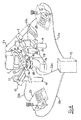
- FIG. 4 shows a variant of the arrangement that has already been described in FIG. 3.
- the arrangement consists of an upright microscope with a manually operated microscope stage 28, an objective changing device 2 with several objectives 3 attached to it and a first micromanipulator 7 and a second micromanipulator 13.
- the microscope functional elements and the micromanipulators 7 and 13 are operated by means of a first common control panel 23 and a second common control panel 24.
- the arrangement is networked with a control unit 12. This is with a control line 26a with the first control panel 23, with a control line 26b with the second control panel 24 and with a control line 26c the microscope 14 and thus its microscope functional elements connected.
- the transmitted light illumination of the biological objects 16 in the vessel 15 takes place with an illumination beam path emanating from a lamp house 17, which is directed onto the biological objects by a condenser 18.
- the embodiment of the arrangement according to the invention shown here has an additional light source. It is a laser 27, the laser beam of which is coupled into an incident light beam path (not shown here) in the upper region of the microscope 14 and is focused on the biological objects with one of the objectives 3.
- the laser can be either a UV or an IR laser. If the biological objects are to be processed using laser cutting (laser microdissection), a UV laser is used. The UV laser beam is then used in the focused state for cutting on the biological objects. Alternatively, an IR laser can be used, the laser beam of which can also be focused on a biological object 16 with an objective 3. The biological object 16 (or parts thereof) captured by the focus of the IR laser beam is drawn into this laser focus and can then be held by moving the laser focus and moved with the laser focus. This principle is often referred to as "optical tweezers". To control the UV laser and / or the IR laser, an operating element 9, which serves to control the laser functions, is arranged on at least one of the control panels 23, 24. The laser functions can be: switching on / off or controlling the pulse rate (with pulsed lasers) or focus / defocus at the location of the biological objects or increasing / decreasing the intensity.
- control panels 23 and 24 can have different control elements 9. However, it has proven to be advantageous if the two control panels 23, 24 are constructed identically, so that all functions that can be addressed by means of the control elements 9 both with the left hand as well as the right hand of the user of the arrangement can be addressed.
- FIG. 5 shows an arrangement according to the invention with an inverted microscope 1 which has a motorized microscope stage 4.
- a transmitted light illumination beam path emanating from a lamp house 17 is directed by a condenser 18, which is motorized here, onto biological objects 16 which are arranged on a specimen slide 29.
- a plurality of objectives 3 are arranged on an objective changing device 2.
- the microscope image of the biological objects 16 can be observed visually by means of eyepieces 30.
- a first micromanipulator 7 and a second micromanipulator 13 are arranged on the microscope 1.
- the arrangement has two control panels 23 and 24 for operating the microscope functional elements and the two micromanipulators 7, 13.
- the control panel 23 is connected to the micromanipulator 7 with a control line 25a and the control panel 24 is connected to the micromanipulator 13 with a control line 25b.
- the arrangement is assigned to a control unit 12 for networking the control panels 23, 24, the microscope 1 with its microscope functional elements and the two micromanipulators 7, 13.
- the control unit 12 is connected to the control panel 23 with a control line 26a, to the control panel 24 with a control line 26 and to the microscope 1 with a control line 26c.
- Several control elements 9 are arranged on the control panels 23 and 24, which allow the microscope functional elements and the two micromanipulators 7 and 13 to be operated.
- the microscope 1 also has control elements 9 for actuating its microscope functional elements. In this way, it is possible to operate certain functions both from one of the control panels 23 or 24 and from the microscope 1.
- both the control panel 23 and the control panel 24 and the microscope 1 have one z drive button 31 for focusing the microscope.
- the technical implementation of the focusing can consist in the height adjustment of the microscope table 4 or in the height adjustment of the objectives 3 or the objective changing device 2.
- the microscope 1 is equipped with a fluorescent lamp house 32.
- a motorized fluorescence filter slide 33 is arranged in the fluorescence beam path (not shown) emanating from this fluorescent lamp house 32.
- a tube lens changing device 34 is arranged with a plurality of tube lenses attached thereon. Since the tube lenses with the lenses 3 represent a compensation system with regard to the image correction of the microscope image, the appropriate tube lens must be assigned to the correct lens 3.
- the motorized tube lens changing device 34 makes it possible for the user to conveniently carry out this assignment at any time.
- a plurality of video outputs 35 are attached in the imaging beam path.
- a camera adapter and a camera are attached to these video outputs 35.
- the microscope image is then transferred to the camera and can be displayed on a monitor.
- a motorized video output control (not shown here) is provided in the lower part of the microscope 1.
- the partial deflection of the imaging light can take place by means of motor-driven prisms or filters or beam splitters, in that either an intensity distribution of the imaging light or a color division (ie by selection of certain wavelength ranges) is carried out.
- This video output control can be operated by a respective assigned control element 9 be carried out both on the control panel 23 and the control panel 24.
- the microscope 1 has a motorized transmitted light filter changing device 36. It allows the motorized insertion or removal of color filters, gray filters etc. in the transmitted light beam path. It is operated by an assigned control element 9 on the control panel 23 and / or the control panel 24.
- control panels 23 and 24 can be constructed differently, but advantageously have the same functional elements. So they each have a display element 10, the z. B. can be designed as a pure LCD display, but can also be designed as an interactive display with touch surfaces. Furthermore, the control panels 23 and 24 in the embodiment shown here have a control wheel 37, which can be used, for example, to control the brightness or to adjust incrementally when focusing the lenses or to actuate the z-movement of the micromanipulators 7 and 13. An operating lever 38, which is movable in the manner of a joystick, can optionally be used to control the xy movement of the microscope stage 4 or the xy movement of the micromanipulators 7 and / or 13.
- both the control wheel 37 and the control lever 38 have a double assignment or even multiple assignment with functions.
- the desired function can be activated, for example, by operating one or more of the buttons 39.
- Other of these buttons 39 can be used, for example, to actuate the motorized lens changing device 2 or to select or control certain manipulator operating states.
- the display element 10 serves as an orientation for the user when selecting the desired control element. So the activated operating state, for. B. selected focus position of the capillary tip or selected lens or selected manipulator operating state, can be displayed, and in addition, this can be done on the multiple controls (such as for example, the control wheel 37 or the control lever 38) activated microscope functional element or the currently activated function of the micromanipulators 7 and 13 are displayed.
- An embodiment of the arrangement according to the invention has proven to be particularly advantageous in which a so-called priority monitoring of the two control panels 23 and 24 is carried out by means of the control unit 12. It is recognized by the control unit 12 when, for example, a certain function is placed on the control lever 38 on the control panel 23. This can be done, for example, by pressing buttons, but this can also be done by monitoring the commissioning of the operating lever 38. As soon as the control unit 12 has registered that, for example, the operating lever 38 has been activated for the function "move microscope table in x-direction or y-direction", the other control panel, ie. H. on the control panel 24, this function also placed on the corresponding control lever 38.
Abstract
Description
Die Erfindung betrifft eine Anordnung zum Mikromanipulieren von biologischen Objekten, die ein Mikroskop mit mindestens einem motorisch verstellbaren Mikroskop-Funktionselement und mindestens einem motorisch verstellbaren Mikromanipulator umfasst.The invention relates to an arrangement for micromanipulating biological objects, which comprises a microscope with at least one motor-adjustable microscope functional element and at least one motor-adjustable micromanipulator.
Solche Anordnungen werden verwendet zur Durchführung von mikroskopischen Manipulationen und Injektionen am lebenden Material, wie z.B. Zellverbänden, Gewebe, Organe, Zellen, Zellbestandteilen, Embryos pflanzlicher oder tierischer Art. Bekannt sind Mikromanipulatoren mit mechanischen, hydraulischen, piezo-elektrischen oder motorischen Antrieben. Sie werden mittels Bedienelementen gesteuert. Ein an dem Mikromanipulator gehalterter Injektor, auch als Injektionskapillare bezeichnet, ermöglicht die Injektion von gewünschten Substanzen oder Zellbestandteilen in einzelne Zellen. Es gibt Injektoren mit mechanischen, pneumatischen und hydraulischen Antrieben, die über Bedienelemente gesteuert werden. Die verwendeten Mikroskope besitzen mechanische als auch teilweise motorisch ansteuerbare Funktionen, die mit unterschiedlichen Bedienelementen gesteuert werden.Such arrangements are used to perform microscopic manipulations and injections on the living material, e.g. Cellular structures, tissues, organs, cells, cell components, plant or animal embryos. Micromanipulators with mechanical, hydraulic, piezoelectric or motor drives are known. They are controlled using controls. An injector, also referred to as an injection capillary, held on the micromanipulator enables the injection of desired substances or cell components into individual cells. There are injectors with mechanical, pneumatic and hydraulic drives that are controlled via controls. The microscopes used have mechanical as well as partially motor-controlled functions that are controlled with different operating elements.
Die verwendeten Anordnungen zeichnen sich daher durch eine Vielzahl separater, an verschiedenen Stellen angeordneter Bedienelemente für die Mikroskopfunktionen, den Mikromanipulator und den Injektor aus. Der Benutzer muss daher mit den Händen oft zwischen den verschiedenen Bedienelementen wechseln, was sehr ermüdend ist. Außerdem resultiert daraus ein langsamerer Ablauf des Experiments sowie ein geringerer Durchsatz an Experimenten.The arrangements used are therefore characterized by a large number of separate control elements for the microscope functions, the micromanipulator and the injector which are arranged at different locations. The user therefore often has to switch hands between the various controls, which is very tiring. It also results this results in a slower course of the experiment and a lower throughput of experiments.
Die EP 0 292 899 B1 beschreibt ein Verfahren zur Mikroinjektion in Zellen bzw. zum Absaugen aus einzelnen Zellen oder ganzer Zellen aus Zellkulturen. Die dazu verwendete Vorrichtung besteht aus einem Mikroskop mit einem motorisch xy-verfahrbaren Mikroskoptisch und einem motorisch höhenverstellbaren Mikromanipulator zur Halterung einer Injektionskapillare. Zur motorischen Ansteuerung der Mikroskoptisch-Position und der Höhen-Position des Mikromanipulators werden ein Rechner, ein zugeordneter Monitor und ein Graphiktablett benutzt. Die Einstellung der xy-Position des Mikromanipulators erfolgt mittels zweier Stellknöpfe direkt an dem Mikromanipulator, d.h. an dem Mikroskop.EP 0 292 899 B1 describes a method for microinjection into cells or for aspiration from individual cells or whole cells from cell cultures. The device used for this consists of a microscope with a motorized xy-movable microscope stage and a motorized height-adjustable micromanipulator for holding an injection capillary. A computer, an assigned monitor and a graphics tablet are used for motorized control of the microscope stage position and the height position of the micromanipulator. The setting of the xy position of the micromanipulator is carried out by means of two adjusting knobs directly on the micromanipulator, i.e. on the microscope.
Auch die hier beschriebene Vorrichtung erfordert von dem Benutzer ein ständiges Umgreifen bzw. Umorientieren zwischen dem Rechner, dem Monitor, dem Graphiktablett und den Stellknöpfen für die Einstellung der xy-Position des Mikromanipulators. Auch hier resultiert daraus ein Ermüden des Benutzers sowie ein langsamerer Ablauf des Experiments sowie ein geringerer Durchsatz an Experimenten.The device described here also requires the user to constantly grasp or reorient between the computer, the monitor, the graphics tablet and the adjusting knobs for setting the xy position of the micromanipulator. Here, too, this results in user fatigue and a slower course of the experiment, as well as a lower throughput of experiments.
Es ist daher Aufgabe der vorliegenden Erfindung, eine Anordnung zum Mikromanipulieren von biologischen Objekten anzugeben, welche ein ergonomisches Arbeiten erlaubt und den erzielbaren Durchsatz an Experimenten erhöht.It is therefore an object of the present invention to provide an arrangement for micromanipulating biological objects which allows ergonomic work and increases the achievable throughput of experiments.
Die Aufgabe wird gelöst durch eine Anordnung zum Mikromanipulieren von biologischen Objekten, die ein Mikroskop mit mindestens einem motorisch verstellbaren Mikroskop-Funktionselement und mindestens einem motorisch verstellbaren Mikromanipulator mit einem Injektor umfasst, welche sich dadurch auszeichnet, dass dem Mikroskop und dem mindestens einen Mikromanipulator mindestens ein gemeinsames Bedienpult zugeordnet ist. Das Bedienpult weist mindestens ein Bedienelement zur Bedienung des sowohl mindestens einen motorisch verstellbaren Mikroskop-Funktionselements als auch des mindestens einen motorisch verstellbaren Mikromanipulators auf.The object is achieved by an arrangement for micromanipulating biological objects, which comprises a microscope with at least one motor-adjustable microscope functional element and at least one motor-adjustable micromanipulator with an injector, which is characterized in that the microscope and the at least one micromanipulator have at least one common control panel is assigned. The control panel has at least one control element for operating the at least one motor-adjustable microscope functional element as well as the at least one motor-adjustable micromanipulator.
Als Mikroskop kann sowohl ein inverses als auch ein aufrechtes Mikroskop mit einer Auflichtanordnung oder einer Durchlichtanordnung verwendet werden. Für die Untersuchung von biologischen Objekten ist es üblich, mit einer Durchlichtanordnung zu arbeiten. Bei dem motorisch verstellbaren Mikroskop-Funktionselement kann es sich beispielsweise um eines der folgenden Elemente handeln:
- einen motorisch xy-verfahrbarer oder drehbarer Mikroskoptisch,
- einen motorisch höhenverfahrbaren z-Trieb des Mikroskoptisches oder des Objektivs zur Einstellung der Fokusebene,
- eine motorisch verfahrbare Objektiv-Wechselvorrichtung mit mehreren Objektiven (3) zum wahlweisen Einbringen eines der Objektive (3) in den Beleuchtungsstrahlengang,
- eine motorisch verstellbare Fluoreszenzfilter-Wechseleinrichtung mit mehreren Fluoreszenz-Filtern zur Einstellung eines von mehreren Fluoreszenz-Verfahren,
- eine motorisch verstellbare Durchlichtfilter-Wechseleinrichtung,
- eine motorisch verstellbare Filter-Wechseleinrichtung mit mehreren Filtern zur Einstellung eines von mehreren Kontrastierungsverfahren,
- eine motorisch verstellbare Filter-Wechseleinrichtung mit mehreren Farb- und/oder Dämpfungsfiltern zur Einstellung des Spektrums oder der Helligkeit des Beleuchtungs- und/oder Abbildungslichts des Mikroskops,
- eine motorische Video-Ausgang-Steuerung,
- einen motorisch verstellbaren Kondensor,
- eine motorische Lichtsteuerung oder
- eine motorische Tubuslinsen-Wechseleinrichtung.
- a motorized xy-movable or rotatable microscope stage,
- a motorized height-adjustable z-drive of the microscope stage or the lens for setting the focal plane,
- a motor-driven lens changing device with a plurality of lenses (3) for selectively inserting one of the lenses (3) into the illumination beam path,
- a motor-adjustable fluorescence filter changing device with several fluorescence filters for setting one of several fluorescence methods,
- a motorized transmitted light filter changing device,
- a motor-adjustable filter changing device with several filters for setting one of several contrasting methods,
- a motor-adjustable filter changing device with several color and / or damping filters for setting the spectrum or the brightness of the illumination and / or imaging light of the microscope,
- a motorized video output control,
- a motor-adjustable condenser,
- a motorized light control or
- a motorized tube lens changing device.
Die Bedienung von Kombinationen aus mehreren der genannten Mikroskop-Funktionselemente ist natürlich möglich. Von dem gemeinsamen Bedienpult aus können mittels zugeordneter Bedienelemente sowohl ein beliebiges Mikroskop-Funktionselement als auch der Mikromanipulator bzw. die Mikromanipulatoren bedient werden. Die erfindungsgemäße Anordnung kann ein, zwei oder mehrere Mikromanipulatoren aufweisen.It is of course possible to operate combinations of several of the microscope functional elements mentioned. From the common control panel Any desired microscope functional element as well as the micromanipulator or the micromanipulators can be operated by means of assigned operating elements. The arrangement according to the invention can have one, two or more micromanipulators.
Die Vernetzung der zentral ansprechbaren motorisch verstellbare Mikroskop-Funktionselemente und des mindestens einen motorisch verstellbaren Mikromanipulators kann durch das Bedienpult selber erfolgen. Dazu wird eine entsprechende Steuereinheit in das Bedienpult integriert. Allerdings hat dies den Nachteil, dass die Steuereinheit eine erheblichen Einbauraum erfordert und dadurch das Bedienpult sehr groß wird. Außerdem ist die Wärmeentwicklung nicht unerheblich, was von dem Benutzer nicht immer als angenehm empfunden wird. Es ist auch denkbar, die Steuereinheit in das Mikroskop selbst einzubauen. Allerdings ist dies wegen der Wärmeentwicklung der Steuereinheit ungünstig, weil die zu manipulierenden biologischen Objekte vor zu großen Temperaturen geschützt werden müssen, da es sich meistens um lebende Zellen bzw. Zellkulturen handelt.The control panel itself can network the centrally addressable motor-adjustable microscope functional elements and the at least one motor-adjustable micromanipulator. For this purpose, a corresponding control unit is integrated in the control panel. However, this has the disadvantage that the control unit requires a considerable amount of installation space and the control panel thereby becomes very large. In addition, the heat development is not insignificant, which is not always perceived as pleasant by the user. It is also conceivable to install the control unit in the microscope itself. However, this is disadvantageous because of the heat development of the control unit, because the biological objects to be manipulated must be protected against excessive temperatures, since they are mostly living cells or cell cultures.
Daher ist in einer vorteilhaften Ausführungsform eine separate elektronische Steuereinheit vorgesehen, welche das mindestens eine motorisch verstellbare Mikroskop-Funktionselement, den mindestens einen motorisch verstellbaren Mikromanipulator und das mindestens eine Bedienpult vernetzt. Dazu ist die Steuereinheit mit dem Mikroskop, dem Mikromanipulator und dem Bedienpult verbunden. Die Steuereinheit kann beliebig positioniert werden.Therefore, in an advantageous embodiment, a separate electronic control unit is provided, which networks the at least one motor-adjustable microscope functional element, the at least one motor-adjustable micromanipulator and the at least one control panel. For this purpose, the control unit is connected to the microscope, the micromanipulator and the control panel. The control unit can be positioned anywhere.
In einer vorteilhaften Ausführungsform weist das gemeinsame Bedienpult mindestens ein Speicher-Bedienelement mit einem zugeordnetem Speicher für die Speicherung und den Abruf mindestens einer vordefinierten Fokusebene auf. Damit ist ein schnelles Wieder-Auffinden der Fokusposition für Routinearbeiten möglich. Wenn beispielsweise mehrere Objektive mit unterschiedlichen Abbildungsmaßstäben oder unterschiedlichen Arbeitsabständen verwendet werden, können die unterschiedlichen Fokusebenen über das zugehörige Bedienelement am gemeinsamen Bedienpult gespeichert und abgerufen werden. Bei Abruf der Fokusposition zu einem vorher bestimmten Objektiv, wird dann der höhenverfahrbare z-Trieb des Mikroskoptisches oder des Objektivs bis zum Erreichen der abgespeicherten Fokusebene motorisch verfahren.In an advantageous embodiment, the common control panel has at least one memory control element with an associated memory for storing and recalling at least one predefined focus level. This enables the focus position to be found quickly for routine work. If, for example, several lenses with different image scales or different working distances are used, the different focal planes can be saved and called up via the associated control element on the common control panel. When the focus position is called up a previously determined objective, the height-adjustable z-drive of the microscope stage or the objective is then motorized until the stored focal plane is reached.
Zusätzlich können zu jedem Objektiv mehrere Fokusebenen abgespeichert und nach Betätigen eines zugeordneten Bedienelementes angefahren werden. Dies wird beispielsweise bei Untersuchung von Zellen benutzt, um wahlweise die Oberfläche oder den Zellkern oder die Unterseite der Zelle anzufahren. Eine weitere Fokusebene kann auf die Spitze des Mikromanipulators gelegt werden, um jederzeit nach Betätigen des zugeordneten Bedienelementes die Qualität (z.B. Schärfe, Form, etc.) der Spitze kontrollieren zu können.In addition, several focal planes can be saved for each lens and can be approached after actuating an assigned control element. This is used, for example, when examining cells in order to either target the surface or the cell nucleus or the underside of the cell. Another focus level can be placed on the tip of the micromanipulator so that the quality (e.g. sharpness, shape, etc.) of the tip can be checked at any time after actuating the assigned control element.
In einer vorteilhaften Ausführungsform der erfindungsgemäßen Anordnung kann zu jedem Objektiv ein individueller Wert für die Fokussierschrittweite abgespeichert werden. Diese Fokussierschrittweite gibt an, mit welcher Schrittweite (z.B. eines Schrittmotors) in z-Richtung beim Fokussieren verfahren wird. Bei hoch vergrößernden Objektiven, die sich durch einen geringen Fokussierweg und eine geringe Tiefenschärfe auszeichnen, ist daher eine geringe Fokussierschrittweite erforderlich. Bei schwach vergrößernden Objektiven, die sich durch einen langen Fokussierweg und eine große Tiefenschärfe auszeichnen, ist daher eine große Fokussierschrittweite möglich bzw. erforderlich. Beim Einschwenken eines bestimmten Objektivs (nach Betätigen der Objektiv-Wechselvorrichtung) wird dann die Fokussierschrittweite automatisch auf den vorher abgespeicherten Wert eingestellt, wodurch mit jedem Objektiv ein individuell schnelles bzw. langsames Fokussieren in entsprechend großen oder kleine Schrittweiten erfolgen kann.In an advantageous embodiment of the arrangement according to the invention, an individual value for the focusing step size can be stored for each objective. This focusing step size specifies the step size (e.g. a stepping motor) in which the z-direction is used for focusing. With high magnification lenses, which are characterized by a small focusing path and a shallow depth of field, a small focusing step size is therefore necessary. With weakly magnifying lenses, which are characterized by a long focusing path and a large depth of field, a large focusing step size is therefore possible or necessary. When swiveling in a specific lens (after actuating the lens changing device), the focusing step size is then automatically set to the previously stored value, which means that each lens can be used to focus individually in fast or slow steps in large or small steps.
Weiterhin kann zu jedem Objektiv ein Helligkeitswert abgespeichert werden, wobei typischerweise für schwache vergrößernde (lichtstarke) Objektive ein kleiner Helligkeitswert und für stark vergrößernde (lichtschwache) Objektive ein großer Helligkeitswert vorgewählt wird. Beim Einschwenken eines bestimmten Objektivs (nach Betätigen der Objektiv-Wechselvorrichtung) wird dann die Helligkeit des Beleuchtungslichts automatisch auf den vorher abgespeicherten Helligkeitswert geregelt.Furthermore, a brightness value can be stored for each lens, a small brightness value typically being selected for weakly magnifying (bright) lenses and a large brightness value for strongly magnifying (weakly) lenses. When swiveling in a specific lens (after actuating the lens changing device) then the brightness of the illuminating light is automatically regulated to the previously stored brightness value.
In einer weiteren vorteilhaften Ausgestaltung der Anordnung ist auch für den Mikromanipulator eine Vorauswahl häufig benötigter Positionen möglich. Dazu weist das mindestens eine gemeinsame Bedienpult mindestens ein Speicher-Bedienelement mit einem zugeordnetem Speicher auf, das für die Speicherung und den Abruf mindestens einer vordefinierten Positionseinstellung des motorisch verstellbaren Mikromanipulators, bzw. der motorisch verstellbaren Mikromanipulatoren, auf. Bei den vorgewählten und abgespeicherten Positionen handelt es sich üblicherweise um Positionen bei der Routineanwendung der Mikrokapillare, beispielsweise die Position der Kapillarspitze zum Durchstechen der Zellmembran oder die Position zum Injizieren bestimmter Objekte in den Zellkern.In a further advantageous embodiment of the arrangement, a preselection of frequently required positions is also possible for the micromanipulator. For this purpose, the at least one common control panel has at least one memory control element with an associated memory, which is used for storing and retrieving at least one predefined position setting of the motor-adjustable micromanipulator or the motor-adjustable micromanipulator. The preselected and stored positions are usually positions in the routine use of the microcapillary, for example the position of the capillary tip for piercing the cell membrane or the position for injecting certain objects into the cell nucleus.
Weiterhin kann das motorisch verstellbare Mikroskop-Funktionselement als eine motorisch verstellbare Filter-Wechseleinrichtung mit verschiedenen Filtern ausgebildet sein. Dabei können die Filter beispielsweise zur Einstellung eines von mehreren Kontrastierungsverfahren aufweist. Es kann sich auch um mehrere Fluoreszenz-Filter zur Einstellung eines von mehreren Fluoreszenz-Verfahren handeln.Furthermore, the motor-adjustable microscope functional element can be designed as a motor-adjustable filter changing device with different filters. The filters can have, for example, for setting one of several contrasting methods. It can also be several fluorescence filters for setting one of several fluorescence methods.
Bei Fluoreszenz-Untersuchungen können zusätzlich motorisch verstellbare Graufilter oder Verschlüsse (englisch: "shutter") im Beleuchtungsstrahlengang vorgesehen sein. Diese ermöglichen ein Dämpfen der Intensität oder ein vollständiges Verschließen des Beleuchtungsstrahlengangs, um (beispielsweise in Arbeitspausen) das zu beobachtende und zu manipulierende biologische Objekt vor ungewolltem Erwärmen oder Ausbleichen zu schützen.In the case of fluorescence tests, motor-adjustable gray filters or shutters (English: "shutter") can also be provided in the illumination beam path. These allow the intensity to be attenuated or the lighting beam path to be completely closed in order to protect the biological object to be observed and manipulated (for example, during breaks in work) against unwanted heating or fading.
In einer anderen Variante der Filter-Wechseleinrichtung sind mehrere Farbund/oder Dämpfungsfilter zur Einstellung des Spektrums oder der Helligkeit des Beleuchtungs- und/oder Abbildungslichts des Mikroskops angeordnet.In another variant of the filter changing device, several color and / or attenuation filters are arranged for setting the spectrum or the brightness of the illumination and / or imaging light of the microscope.
In einer vorteilhaften Ausführungsform sind an dem Mikroskop ein Video-Ausgang bzw. mehrere Video-Ausgänge vorgesehen. An jedem Video-Ausgang kann jeweils ein Kamera-Adapter und daran eine Kamera angesetzt werden. Das Mikroskopbild wird dann auf die Kamera übertragen und auf einem Monitor dargestellt. In einer vorteilhaften Ausgestaltung weist die erfindungsgemäße Anordnung als motorisch verstellbares Mikroskop-Funktionselement eine motorisierte Video-Ausgang-Steuerung auf, die das Abbildungslicht ganz oder teilweise auf einen oder mehrere Video-Ausgänge umlenkt. Die teilweise Umlenkung kann mittels motorisch verfahrbarer Prismen oder Filtern bzw. Strahlteilern in Form einer Intensitätsaufteilung oder in Form einer Farbaufteilung (d.h. durch Auswahl bestimmter Wellenlängenbereiche) erfolgen.In an advantageous embodiment, a video output or a plurality of video outputs are provided on the microscope. A camera adapter and a camera can be attached to each video output. The microscope image is then transferred to the camera and displayed on a monitor. In an advantageous embodiment, the arrangement according to the invention, as a motor-adjustable microscope functional element, has a motorized video output control which redirects the imaging light in whole or in part to one or more video outputs. The partial deflection can be carried out by means of motor-driven prisms or filters or beam splitters in the form of an intensity distribution or in the form of a color distribution (i.e. by selection of certain wavelength ranges).
Weitere motorische Mikroskop-Funktionselemente, die über das gemeinsame Bedienpult für das Mikroskop und den Mikromanipulator angesteuert werden können, sind beispielsweise ein motorisch verstellbarer Kondensor und eine motorische Lichtsteuerung. Der motorisch verstellbare Kondensor dient zum Wechseln von im Kondensor angeordneten Komponenten, z.B. zum Wechseln von Phasenringen oder zum Wechseln von Wollaston-Prismen, die für das Differential-Interferenz-Kontrastverfahren (DIC) erforderlich sind. Die motorische Lichtsteuerung dient zur Helligkeitssteuerung im Strahlengang, z.B. durch Einfügen und Entfernen von Filtern und Verschlüssen.Other motorized microscope functional elements that can be controlled via the common control panel for the microscope and the micromanipulator are, for example, a motorized condenser and a motorized light control. The motor-adjustable condenser is used to change components arranged in the condenser, e.g. for changing phase rings or for changing Wollaston prisms, which are required for the differential interference contrast method (DIC). The motorized light control is used to control the brightness in the beam path, e.g. by inserting and removing filters and closures.
Selbstverständlich ist es auch möglich, Kombinationen aus den genannten motorisch verstellbaren Mikroskop-Funktionselementen und dem motorisch verstellbaren Mikromanipulator (bzw. mehreren Mikromanipulatoren) von dem gemeinsamen Bedienpult aus zu steuern.Of course, it is also possible to control combinations of the motor-controlled microscope functional elements and the motor-controlled micromanipulator (or several micromanipulators) from the common control panel.
Dabei ist in einer vorteilhaften Ausführungsform an dem Bedienpult mindestens ein Speicher-Bedienelement mit einem zugeordnetem Speicher vorgesehen, das für die Speicherung und den Abruf mindestens einer vordefinierten Einstellung mindestens eines der motorisch verstellbaren Mikroskop-Funktionselemente vorgesehen ist.In an advantageous embodiment, at least one memory control element with an associated memory is provided on the control panel, which is provided for storing and retrieving at least one predefined setting of at least one of the motor-adjustable microscope functional elements.
Das Bedienpult kann am Mikroskop angeordnet oder auch in das Mikroskop-Gehäuse integriert sein. Als besonders vorteilhaft hat sich erwiesen, wenn das Bedienpult separat vom Mikroskop angeordnet ist, da dann die Position des Bedienpultes, z. B. auf dem Labortisch, von dem Benutzer entsprechend seiner individuellen Ergonomie selbst gewählt werden kann.The control panel can be arranged on the microscope or can also be integrated into the microscope housing. It has proven to be particularly advantageous if the control panel is arranged separately from the microscope, since the position of the control panel, for. B. on the laboratory table, by the user can be chosen according to his individual ergonomics.
Wenn an dem Mikroskop zwei oder mehr Mikromanipulatoren angeordnet sind, kann ein einziges Bedienpult vorgesehen werden, das jeweils mindestens ein Bedienelement für mindestens einen der Mikromanipulatoren aufweist. Dies hängt davon ab, welche Funktionen an dem Mikromanipulator motorisiert zur Verfügung stehen.If two or more micromanipulators are arranged on the microscope, a single control panel can be provided, each of which has at least one control element for at least one of the micromanipulators. This depends on which functions are motorized available on the micromanipulator.
Wenn an dem Mikroskop insbesondere genau zwei Mikromanipulatoren angeordnet sind, kann ein einziges Bedienpult angeordnet werden, das zwei separate Bedienelemente für die jeweilige xy-Verstellung und/oder die Höhenverstellung der beiden Mikromanipulatoren aufweist. Dabei erweist sich eine Ausführungsform als besonders benutzerfreundlich, bei der diese beiden Bedienelemente je einer Hand eines Benutzers zugeordnet sind. Diese handspezifische Zuordnung erweist sich als sehr benutzerfreundlich, da sie dem Benutzer von Mikroskopen, z.B. von der manuellen Verstellung des Mikroskoptisches, vertraut ist.If exactly two micromanipulators are arranged on the microscope, a single control panel can be arranged which has two separate operating elements for the respective xy adjustment and / or the height adjustment of the two micromanipulators. In this case, an embodiment proves to be particularly user-friendly, in which these two control elements are each assigned to a hand of a user. This hand-specific assignment proves to be very user-friendly, since it can be used by the user of microscopes, e.g. from the manual adjustment of the microscope stage.
Wenn an dem Mikroskop zwei oder mehr Mikromanipulatoren angeordnet sind können zwei gemeinsame Bedienpulte vorgesehen werden, von denen jedes mindestens ein Bedienelement für mindestens einen der Mikromanipulatoren und mindestens ein motorisch verstellbares Mikroskop-Funktionselement aufweist. Durch die Verwendung von zwei Bedienpulten können beispielsweise die Bedienelemente, die entweder bestimmten Funktionen oder bestimmten Mikroskop-Funktionselementen oder Mikromanipulatoren zugeordnet sind, auf dem einen bzw. dem anderen Bedienpult gruppiert werden. Dies erleichtert das Erlernen der Bedienung durch den Benutzer erheblich.If two or more micromanipulators are arranged on the microscope, two common operating desks can be provided, each of which has at least one operating element for at least one of the micromanipulators and at least one motor-adjustable microscope functional element. By using two control panels, for example, the control elements, which are assigned either to specific functions or to specific microscope function elements or micromanipulators, can be grouped on one or the other control panel. This considerably facilitates the learning of the operation by the user.
Um eine weiter gehende Nutzung der Anordnung zu erzielen, wird der Anordnung ein UV-Laser zugeordnet wird, dessen Laserstrahl mit einer Einkoppeloptik in das Mikroskop eingekoppelt wird. Zum Laserschneiden eines biologischen Objekts wird dieser eingekoppelte Laserstrahl mit einem Objektiv auf das biologische Objekt fokussiert. Damit wird in Ergänzung zu den Mikromanipulatoren bzw. den Injektoren die Funktionalität der Anordnung erheblich verbessert, da dadurch eine vor- oder nachbereitende Präparation mittels Laser-Mikrodissektion (Laser-Mikro-Schneiden) der zu manipulierenden biologischen Objekte möglich ist. Weiterhin kann der Anordnung ein IR-Laser zugeordnet sein, dessen Laserstrahl mit einer Einkoppeloptik in das Mikroskop eingekoppelt und mit einem Objektiv auf das biologische Objekt fokussiert wird. Der fokussierte IR-Laserstrahl wird zum Erfassen, Halten und Bewegen des biologischen Objekts verwendet. Zur Ansteuerung des UV-Lasers und/oder des IR-Lasers ist auf dem (mindestens einen) Bedienpult mindestens ein Bedienelement zur Steuerung der Laserfunktionen (z.B. An/Aus oder Fokus/Defokus) angeordnet.In order to achieve further use of the arrangement, the arrangement is assigned a UV laser, the laser beam of which is coupled into the microscope with a coupling optic. For laser cutting a biological object, this coupled laser beam is focused on the biological object with a lens. In addition to the micromanipulators or the injectors, the functionality of the arrangement is thus considerably improved, since this enables preparatory or subsequent preparation by means of laser microdissection (laser micro cutting) of the biological objects to be manipulated. Furthermore, an IR laser can be assigned to the arrangement, the laser beam of which is coupled into the microscope with a coupling optics and focused onto the biological object with a lens. The focused IR laser beam is used to detect, hold and move the biological object. To control the UV laser and / or the IR laser, at least one control element for controlling the laser functions (e.g. on / off or focus / defocus) is arranged on the (at least one) control panel.
Wesentlicher Teil der erfindungsgemäßen Anordnung ist ein zentral angeordnetes, für das Mikroskop und den Mikromanipulator bzw. die Mikromanipulatoren gemeinsam wirkendes Bedienpult, mit dem die wichtigsten Funktionen des Mikroskops, des Mikroskoptisches sowie des Mikromanipulators zentral ausgeführt werden können. Die Bedienelemente sind so am Bedienpult angebracht, dass die Hände des Benutzers während des Arbeitens am Bedienpult bleiben können und alle Funktionen raumnah erreicht werden können. Durch eine ergonomische und anwenderfreundlichen Gestaltung des Bedienpults wird ein Ermüden der Hände und der Handgelenke vermieden.An essential part of the arrangement according to the invention is a centrally arranged control panel which acts jointly for the microscope and the micromanipulator or the micromanipulators and with which the most important functions of the microscope, the microscope table and the micromanipulator can be carried out centrally. The controls are attached to the control panel in such a way that the user's hands can remain on the control panel while working and all functions can be accessed close to the room. The ergonomic and user-friendly design of the control panel prevents tired hands and wrists.
Die Erfindung wird nachfolgend anhand der schematischen Zeichnung näher erläutert. Es zeigen:
- Fig. 1:
- eine Anordnung zum Mikromanipulieren von biologischen Objekten mit einem inversen Mikroskop, einem Mikromanipulator und einem gemeinsamen Bedienpult;
- Fig. 2:
- eine Anordnung zum Mikromanipulieren von biologischen Objekten mit einem inversen Mikroskop, zwei Mikromanipulatoren und einem gemeinsamen Bedienpult;
- Fig. 3:
- eine Anordnung zum Mikromanipulieren von biologischen Objekten mit einem aufrechten Mikroskop, zwei Mikromanipulatoren und zwei gemeinsamen Bedienpulten;
- Fig. 4 :
- eine Anordnung zum Mikromanipulieren von biologischen Objekten mit einem aufrechten Mikroskop mit einem eingekoppelten Laserstrahl, zwei Mikromanipulatoren und zwei gemeinsamen Bedienpulten;
- Fig. 5 :
- eine Anordnung zum Mikromanipulieren von biologischen Objekten mit einem inversen Mikroskop, zwei Mikromanipulatoren und zwei gemeinsamen Bedienpulten;
- Fig. 1 :
- an arrangement for micromanipulating biological objects with an inverted microscope, a micromanipulator and a common control panel;
- Fig. 2 :
- an arrangement for micromanipulating biological objects with an inverted microscope, two micromanipulators and a common control panel;
- Fig. 3 :
- an arrangement for micromanipulating biological objects with an upright microscope, two micromanipulators and two common control panels;
- Fig. 4 :
- an arrangement for micromanipulating biological objects with an upright microscope with a coupled laser beam, two micromanipulators and two common control panels;
- Fig. 5 :
- an arrangement for micromanipulating biological objects with an inverted microscope, two micromanipulators and two common control panels;
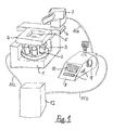
Fig. 1 zeigt eine Anordnung zum Mikromanipulieren von biologischen Objekten, die auf einem inversen Mikroskop 1 basiert. Das Mikroskop 1 ist stark schematisiert dargestellt, um eine gute Übersichtlichkeit der Darstellung zu erreichen. An dem Mikroskop 1 ist eine Objektiv-Wechselvorrichtung 2 mit mehreren Objektiven 3 angeordnet. Oberhalb der Objektive 3 ist an dem inversen Mikroskop 1 ein motorisierter Mikroskoptisch 4 zur Aufnahme von biologischen Objekten (hier nicht dargestellt) angeordnet. Der Mikroskoptisch 4 weist eine innenliegende Öffnung 5 auf, durch welche die biologischen Objekte im Durchlicht beleuchtet und betrachtet werden können. Dazu ist oberhalb des Mikroskoptischs 4 ein Beleuchtungsstrahlengang mit einem Kondensor (beides nicht dargestellt) angeordnet. An dem Mikroskop 1 ist ein Adapter 6 angebracht, der zur Befestigung von Mikromanipulatoren vorgesehen ist. An diesem Adapter 6 ist ein motorisierter Mikromanipulator 7 angeordnet. Die Antriebe für die Bewegung des Mikromanipulators 7 in den drei Raumrichtungen x, y, und z sind zur Vereinfachung nicht dargestellt. 1 shows an arrangement for micromanipulating biological objects, which is based on an
Für das Mikroskop 1 und den Mikromanipulator 7 ist ein gemeinsames Bedienpult 8 vorgesehen. Das Bedienpult 8 weist mehrere Bedienelemente 9 zur Bedienung der motorisch verstellbaren Mikroskop-Funktionselemente sowie des motorisierten Mikromanipulators 7 auf. Der Begriff "motorisch verstellbare Mikroskop-Funktionselemente" ist als übergreifende Sammelbezeichnung für alle Funktionselemente am Mikroskop zu verstehen, die motorisch verstellbar sind. Dabei kann es sich im dargestellten Beispiel sowohl um die Objektiv-Wechselvorrichtung 2 als auch um den motorisierten Mikroskoptisch 4 handeln. Die Bedienelemente 9 können jeweils bestimmten Mikroskop-Funktionselementen oder bestimmten Funktionen des Mikromanipulators 7 zugeordnet sein. Es ist aber auch denkbar, ein Bedienelement 9 mehreren Funktionselementen bzw. Mikromanipulator-Funktionen zuzuordnen, wobei die jeweils gewünschte Funktion aktiviert werden kann. In dem vorliegenden Beispiel weist das Bedienpult 8 zusätzlich ein Anzeigeelement 10 (z. B. ein LCD-Display) auf, mit dem die angesprochenen Mikroskop-Funktionselemente oder die vorgenommenen Einstellungen an dem inversen Mikroskop 1 oder an dem Mikromanipulator 7 angezeigt werden können.A
Das Bedienpult 8 ist mit einer Steuerleitung 11 a mit dem motorisierten Mikromanipulator 7 und mit einer Steuerleitung 11b mit einer separat angeordneten Steuereinheit 12 verbunden. Diese Steuereinheit 12 wiederum ist mit einer Steuerleitung 11c mit den motorisierten Mikroskop-Funktionselementen im Mikroskop 1 verbunden. Diese Steuereinheit 12 dient dazu, die motorisch verstellbaren Mikroskop-Funktionselemente und den motorisch verstellbaren Mikromanipulator 7 und das gemeinsame Bedienpult 8 zu vernetzen. Es ist natürlich auch möglich, die Steuereinheit 12 entweder in das Bedienpult 8 oder in das inverse Mikroskop 1 zu integrieren. Da jedoch von der Steuereinheit 12 eine erhebliche Wärmeentwicklung ausgeht, wurde in der hier dargestellten Ausführung der Anordnung zum Mikromanipulieren von biologischen Objekten die Steuereinheit 12 separat angeordnet. In der Fig. 1 erscheint es, als wenn diese Steuereinheit 12 auf demselben Labortisch wie das Mikroskop 1 und das Bedienpult 8 stünde. Dies ist jedoch nur aus Gründen der Anschaulichkeit so dargestellt. In der Realität wird die Steuereinheit 12 möglichst weit entfernt von dem Mikroskop 1 aufgestellt, beispielsweise unter dem Labortisch. Damit ist dann auch für einen Benutzer der erfindungsgemäßen Anordnung das Bedienpult 8 leicht und ergonomisch zugänglich.The
Fig. 2 zeigt eine Anordnung zum Mikromanipulieren von biologischen Objekten, die gegenüber der Darstellung in Fig. 1 mit einem zweiten Mikromanipulator ausgestattet ist. FIG. 2 shows an arrangement for micromanipulating biological objects, which is equipped with a second micromanipulator compared to the representation in FIG. 1.
Ein inverses Mikroskop 1 weist eine Objektiv-Wechselvorrichtung 2 mit mehreren daran befestigten Objektiven 3 und einen motorisierten Mikroskoptisch 4 auf. Aus Gründen der Übersichtlichkeit der Darstellung wurde ein oberhalb des Mikroskoptisches 4 angeordneter Beleuchtungsstrahlengang mit einem Kondensor hier nicht dargestellt.An
An dem Mikroskop 1 ist ein Adapter 6 angebracht, der zur Befestigung von Mikromanipulatoren dient. Auf diesem Adapter 6 sind ein erster motorisierter Mikromanipulator 7 und ein zweiter motorisierter Mikromanipulator 13 befestigt. Beide Mikromanipulatoren 7, 13 können in den drei Raumrichtungen x, y und z bewegt werden. Sie dienen zur Aufnahme von Injektoren (hier nicht dargestellt), mit denen biologische Objekte manipuliert werden können. Die Art der Manipulation kann das Einspritzen oder Aussaugen von Flüssigkeiten oder Zellkomponenten oder ähnliche Eingriffe umfassen.An
Dem Mikroskop 1 mit seinen motorisierten Mikroskop-Funktionselementen, hier der motorisierten Objektiv-Wechselvorrichtung 2 und dem motorisierten Mikroskoptisch 4, und den beiden Mikromanipulatoren 7 und 13 ist ein gemeinsames Bedienpult 8 zugeordnet. Dieses Bedienpult 8 ist mit einer Steuerleitung 11a mit dem ersten motorisierten Mikromanipulator 7 und mittels einer Steuerleitung 11d mit dem zweiten motorisierten Mikromanipulator 13 verbunden.The
Der Anordnung ist eine Steuereinheit 12 zugeordnet, die mit einer Steuerleitung 11b mit dem Bedienpult 8 und mit einer Steuerleitung 11c mit dem Mikroskop 1, d. h. mit den motorisierten Mikroskop-Funktionselementen, verbunden ist. Die Steuereinheit 12 vernetzt die von dem Bedienpult 8 angesprochenen Funktionselemente des Mikroskops 1 und die gesteuerten Mikromanipulatoren 7, 13. In der Steuereinheit 12 oder dem Bedienpult 8 sind Speicher (Datenspeicher oder Bildspeicher) zum Ablegen bestimmter Informationen, die für die Bedienung der Mikroskop-Funktionselemente oder der Mikromanipulatoren 7, 13 erforderlich sind, vorgesehen. Das Bedienpult 8 weist mehrere Bedienelemente 9 auf, die den verschiedenen motorisch betriebenen Funktionselementen des Mikroskops 1 und/oder den beiden Mikromanipulatoren 7, 13 (oder auch nur einem von diesen) zugeordnet sind. Einzelheiten zu den Bedienelementen sind bei Fig. 4 beschrieben. Die dargestellte Art der Vernetzung von Mikroskop 1, Mikromanipulatoren 7, 13, Bedienpult 8 und Steuereinheit 12 kann auch anders als in der hier dargestellten Weise erfolgen. Die Art der Vernetzung ist beispielsweise abhängig von den verwendeten Schnittstellen oder Daten-Übertragungsprotokollen.The arrangement is assigned a
Die Steuereinheit 12 kann auch in das Mikroskop 1 oder das Bedienpult 8 integriert sein. Um jedoch eine unerwünschte Wärmeentwicklung von dem Mikroskop 1 fernzuhalten, wurde in der hier dargestellten Anordnung eine separate Aufstellung der Steuereinheit 12 vorgezogen.The
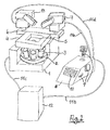
Fig. 3 zeigt eine erfindungsgemäße Anordnung zum Mikromanipulieren von biologischen Objekten, in der zwei Bedienpulte einem Mikroskop mit zwei zugeordneten Mikromanipulatoren vorgesehen sind. 3 shows an arrangement according to the invention for micromanipulating biological objects, in which two control panels are provided for a microscope with two assigned micromanipulators.
Ein aufrechtes Mikroskop 14 weist eine motorisierte Objektiv-Wechselvorrichtung 2 mit mehreren daran angeordneten Objektiven 3 auf. Ein motorisierter Mikroskoptisch 4 (Antriebe nicht dargestellt) dient zur Aufnahme eines Gefäßes 15 mit darauf befindlichen biologischen Objekten 16. Von einem an dem Mikroskop 14 angeordneten Lampenhaus 17 geht ein (hier nicht dargestellter) Beleuchtungsstrahlengang aus, der durch einen Kondensor 18 auf die biologischen Objekte 16 gerichtet wird.An upright microscope 14 has a motorized lens changing device 2 with a plurality of
Zum Manipulieren der biologischen Objekte 16 sind ein erster motorisierter Mikromanipulator 7 und ein zweiter motorisierter Mikromanipulator 13 vorgesehen. Sie sind in dem hier dargestellten Beispiel separat vom Mikroskop auf Tragelementen 19 befestigt, welche mit dem Mikroskop nicht verbunden sind. Es ist aber auch denkbar, die Mikromanipulatoren so mit dem Mikroskop zu verbinden, wie es in den Fig. 1 und 2 bereits dargestellt wurde, also mittels eines Adapters direkt am Mikroskop.A first
An dem ersten motorisierten Mikromanipulator 7 ist ein erster Injektor 20 und an dem zweiten motorisierten Mikromanipulator 13 ist ein zweiter Injektor 21 angeordnet. Die erforderlichen Druck-Steuerungseinrichtungen zur Steuerung des Drucks in den Injektoren 20, 21 (z. B. zum Injizieren oder zum Extrahieren von Flüssigkeiten oder Zellbestandteilen) sind zur Vereinfachung nicht dargestellt. Die Manipulationen an den biologischen Objekten werden mit Mikrokapillaren 22 vorgenommen, die an den Injektoren 20, 21 angeschlossen sind. Zum Durchführen exakter Operationen an den biologischen Objekten 16 (z.B. Injizieren von Flüssigkeiten oder Zellmaterial) muss die Spitze der jeweils angesteuerten Mikrokapillare 22 exakt positioniert werden.A
Die Anordnung weist ein erstes Bedienpult 23 und ein zweites Bedienpult 24 auf. Das erste Bedienpult 23 ist mit einer Steuerleitung 25a mit dem ersten Mikromanipulator 7 verbunden. Das zweite Bedienpult 24 ist mit einer Steuerleitung 25b mit dem zweiten Mikromanipulator 13 verbunden. Zur Vernetzung des Mikroskops 14, der Mikromanipulatoren 7 und 13 sowie der beiden Bedienpulte 23 und 24 weist die Anordnung eine Steuereinheit 12 auf, welche diese Komponenten der Anordnung miteinander vernetzt. Dazu ist die Steuereinheit 12 mit einer Steuerleitung 26a mit dem ersten Bedienpult 23, mit einer Steuerleitung 26b mit dem zweiten Bedienpult 24 sowie mit einer Steuerleitung 26c mit dem Mikroskop 14 bzw. den motorisierten motorisch verstellbaren Mikroskop-Funktionselementen verbunden.The arrangement has a
Die Steuereinheit 12 ist so konzipiert, dass die Bedienung des Mikroskops 14 bzw. seiner motorisierten Mikroskop-Funktionselemente (hier des motorisierten Mikroskoptischs 4 und der motorisierten Objektiv-Wechselvorrichtung 2) sowie der beiden Mikromanipulatoren 7 und 13 alternativ sowohl von dem ersten Bedienpult 23 als auch von dem zweiten Bedienpult 24 aus erfolgen kann. Dazu weisen die beiden Bedienpulte 23, 24 eine Reihe von Bedienelementen 9 auf, die den verschiedenen motorisierten Funktionen am Mikroskop 14 oder den Mikromanipulatoren 7, 13 zugeordnet sind oder zugeordnet werden können. Einzelheiten zu den Bedienelementen 9 werden bei Fig. 5 beschrieben.The
Die Steuereinheit 12 kann in das Mikroskop 14 oder in eines oder beide der Bedienpulte 23, 24 integriert werden. Da jedoch von der Steuereinheit 12, die Elektronik enthält, eine erhebliche Wärmeentwicklung ausgeht, wurde in der hier dargestellten Anordnung die Steuereinheit 12 separat aufgestellt. Damit wird eine unnötige Erwärmung der biologischen Elemente 16 vermieden. Ein weiterer Vorteil der separaten Anordnung der Steuereinheit 12 besteht darin, dass das Mikroskop 14 mit den daneben angeordneten Mikromanipulatoren 7, 13 in eine kleine, räumlich begrenzte Klimakammer (hier nicht dargestellt) eingebracht werden kann, während die Steuereinheit 12 außerhalb der Klimakammer angeordnet wird.The
Fig. 4 zeigt eine Variante zu der Anordnung, die bereits in Fig. 3 beschrieben wurde. Die Anordnung besteht aus einem aufrechten Mikroskop mit einem manuell zu betätigenden Mikroskoptisch 28, einer Objektiv-Wechselvorrichtung 2 mit mehreren daran gehalterten Objektiven 3 und einem ersten Mikromanipulator 7 sowie einem zweiten Mikromanipulator 13. Die Bedienung der Mikroskop-Funktionselemente und der Mikromanipulatoren 7 und 13 erfolgt durch ein erstes gemeinsames Bedienpult 23 und ein zweites gemeinsames Bedienpult 24. Die Vernetzung der Anordnung erfolgt mit einer Steuereinheit 12. Diese ist mit einer Steuerleitung 26a mit dem ersten Bedienpult 23, mit einer Steuerleitung 26b mit dem zweiten Bedienpult 24 und mit einer Steuerleitung 26c mit dem Mikroskop 14 und damit seinen Mikroskop-Funktionselementen verbunden. FIG. 4 shows a variant of the arrangement that has already been described in FIG. 3. The arrangement consists of an upright microscope with a manually operated
Die Durchlichtbeleuchtung der biologischen Objekte 16 in dem Gefäß 15 erfolgt mit einem von einem Lampenhaus 17 ausgehenden Beleuchtungsstrahlengang, der durch einen Kondensor 18 auf die biologischen Objekte gerichtet ist.The transmitted light illumination of the
Zusätzlich zu der in Fig. 3 gezeigten Anordnung weist die hier dargestellte Ausführungsform der erfindungsgemäßen Anordnung eine zusätzliche Lichtquelle auf. Es handelt sich um einen Laser 27, dessen Laserstrahl im oberen Bereich des Mikroskops 14 in einen Auflichtstrahlengang (hier nicht dargestellt) eingekoppelt wird und mit einem der Objektive 3 auf die biologischen Objekte fokussiert wird.In addition to the arrangement shown in FIG. 3, the embodiment of the arrangement according to the invention shown here has an additional light source. It is a
Bei dem Laser kann es sich entweder um einen UV- oder einen IR-Laser handeln. Wenn die biologischen Objekte mittels Laserschneiden (Lasermikrodissektion) bearbeitet werden sollen, wird ein UV-Laser verwendet. Der UV-Laserstrahl wird dann im fokussierten Zustand zum Schneiden an den biologischen Objekten verwendet. Alternativ kann ein IR-Laser verwendet werden, dessen Laserstrahl ebenfalls mit einem Objektiv 3 auf ein biologisches Objekt 16 fokussiert werden kann. Das vom Fokus des IR-Laserstrahls erfasste biologische Objekt 16 (oder Teile davon) wird in diesen Laser-Fokus hineingezogen und kann dann durch Bewegen des Laser-Fokus festgehalten und mit dem Laser-Fokus mitbewegt werden. Dieses Prinzip wird häufig auch als "optische Pinzette" bezeichnet. Zur Ansteuerung des UV-Lasers und/oder des IR-Lasers ist auf mindestens einem der Bedienpulte 23, 24 ein Bedienelement 9 angeordnet, das zur Steuerung der Laserfunktionen dient. Bei den Laserfunktionen kann es sich handeln um: Einschalten/Ausschalten oder Steuerung der Pulsrate (bei gepulsten Lasern) oder Fokus/Defokus am Ort der biologischen Objekte oder Erhöhen/Erniedrigen der Intensität.The laser can be either a UV or an IR laser. If the biological objects are to be processed using laser cutting (laser microdissection), a UV laser is used. The UV laser beam is then used in the focused state for cutting on the biological objects. Alternatively, an IR laser can be used, the laser beam of which can also be focused on a
Die Bedienpulte 23 und 24 können unterschiedliche Bedienelemente 9 aufweisen. Es hat sich jedoch als vorteilhaft erwiesen, wenn die beiden Bedienpulte 23, 24 identisch aufgebaut sind, so dass sämtliche Funktionen, die mittels der Bedienelemente 9 angesprochen werden können, sowohl mit der linken Hand als auch der rechten Hand des Benutzers der Anordnung angesprochen werden können.The
Fig. 5 zeigt eine erfindungsgemäße Anordnung mit einem inversen Mikroskop 1, das einen motorisierten Mikroskoptisch 4 aufweist. Ein von einem Lampenhaus 17 ausgehender Durchlichtbeleuchtungsstrahlengang (hier nicht dargestellt) wird durch einen Kondensor 18, der hier motorisiert ausgebildet ist, auf biologische Objekte 16 gerichtet, die auf einem Objektträger 29 angeordnet sind. Unterhalb des rahmenförmigen Mikroskoptischs 4 sind mehrere Objektive 3 an einer Objektiv-Wechselvorrichtung 2 angeordnet. Die visuelle Beobachtung des Mikroskopbilds der biologischen Objekte 16 kann durch Okulare 30 erfolgen. An dem Mikroskop 1 sind ein erster Mikromanipulator 7 und ein zweiter Mikromanipulator 13 angeordnet. 5 shows an arrangement according to the invention with an
Zur Bedienung der Mikroskop-Funktionselemente und der beiden Mikromanipulatoren 7, 13 weist die Anordnung zwei Bedienpulte 23 und 24 auf. Das Bedienpult 23 ist mit einer Steuerleitung 25a mit dem Mikromanipulator 7 und das Bedienpult 24 ist mit einer Steuerleitung 25b mit dem Mikromanipulator 13 verbunden. Der Anordnung ist einer Steuereinheit 12 zur Vernetzung der Bedienpulte 23, 24, des Mikroskops 1 mit seinen Mikroskop-Funktionselementen und der beiden Mikromanipulatoren 7, 13 zugeordnet. Die Steuereinheit 12 ist mit einer Steuerleitung 26a mit dem Bedienpult 23, mit einer Steuerleitung 26b mit dem Bedienpult 24 und mit einer Steuerleitung 26c mit dem Mikroskop 1 verbunden. An den Bedienpulten 23 und 24 sind mehrere Bedienelemente 9 angeordnet, die eine Bedienung der Mikroskop-Funktionselemente und der beiden Mikromanipulatoren 7 und 13 erlauben.The arrangement has two
In der hier dargestellten, besonders vorteilhaften Ausführungsform weist auch das Mikroskop 1 Bedienelemente 9 zur Betätigung seiner Mikroskop-Funktionselemente auf. Auf diese Weise ist es möglich, sowohl von einem der Bedienpulte 23 oder 24 als auch vom Mikroskop 1 aus selber die Bedienung bestimmter Funktionen vorzunehmen. So weist beispielsweise sowohl das Bedienpult 23 als auch das Bedienpult 24 und das Mikroskop 1 einen z-Triebknopf 31 zur Fokussierung des Mikroskops auf. Die technische Ausführung der Fokussierung kann in der Höhenverstellung des Mikroskoptisches 4 oder in der Höhenverstellung der Objektive 3 bzw. der Objektiv-Wechselvorrichtung 2 bestehen.In the particularly advantageous embodiment shown here, the
Nachstehend sollen einige der Mikroskop-Funktionselemente, die motorisiert ausgeführt sein können, näher erläutert werden. Das Mikroskop 1 ist zusätzlich zu dem Durchlichtlampenhaus 17 mit einem Fluoreszenzlampenhaus 32 ausgestattet. In dem von diesem Fluoreszenzlampenhaus 32 ausgehenden Fluoreszenzstrahlengang (nicht dargestellt) ist ein motorisierter Fluoreszenzfilter-Schieber 33 angeordnet. Im Abbildungsstrahlengang (hier nicht dargestellt) ist eine Tubuslinsen-Wechselvorrichtung 34 mit mehreren darauf angebrachten Tubuslinsen angeordnet. Da die Tubuslinsen mit den Objektiven 3 bezüglich der Bildkorrektur des Mikroskopbildes ein Kompensationssystem darstellen, muss jeweils die passende Tubuslinse dem richtigen Objektiv 3 zugeordnet werden. Mittels der motorisierten Tubuslinsen-Wechselvorrichtung 34 ist es für den Benutzer auf komfortable Weise möglich, diese Zuordnung jederzeit passend vorzunehmen.Some of the microscope functional elements that can be motorized will be explained in more detail below. In addition to the transmitted
Ebenso im Abbildungsstrahlengang sind mehrere Video-Ausgänge 35, von denen hier beispielhaft nur einer abgebildet ist, angebracht. An diesen Video-Ausgängen 35 wird ein Kamera-Adapter und daran eine Kamera (hier nicht dargestellt) angesetzt. Das Mikroskopbild wird dann auf die Kamera übertragen und kann auf einem Monitor dargestellt werden. Um das Abbildungslicht des Abbildungsstrahlengangs ganz oder teilweise auf einen oder mehrere dieser Video-Ausgänge 35 umzulenken, ist im unteren Teil des Mikroskops 1 eine motorisierte Video-Ausgang-Steuerung (hier nicht dargestellt) vorgesehen. Die teilweise Umlenkung des Abbildungslichts kann mittels motorisch beweglicher Prismen oder Filtern bzw. Strahlteilern dadurch geschehen, dass entweder eine Intensitätsaufteilung des Abbildungslichts oder eine Farbaufteilung (d. h. durch Auswahl bestimmter Wellenlängenbereiche) vorgenommen wir. Die Bedienung dieser Video-Ausgang-Steuerung kann durch ein jeweils zugeordnetes Bedienelement 9 sowohl auf dem Bedienpult 23 als auch dem Bedienpult 24 vorgenommen werden.Likewise, a plurality of video outputs 35, of which only one is shown here by way of example, are attached in the imaging beam path. A camera adapter and a camera (not shown here) are attached to these video outputs 35. The microscope image is then transferred to the camera and can be displayed on a monitor. In order to deflect the imaging light of the imaging beam path in whole or in part onto one or more of these video outputs 35, a motorized video output control (not shown here) is provided in the lower part of the
Als weiteres motorisiertes Mikroskop-Funktionselement weist das Mikroskop 1 eine motorisierte Durchlichtfilter-Wechselvorrichtung 36 auf. Sie erlaubt das motorisierte Einbringen bzw. Entfernen von Farbfiltern, Graufiltern etc. in den Durchlichtstrahlengang. Die Bedienung erfolgt durch ein zugeordnetes Bedienelement 9 auf dem Bedienpult 23 und/oder dem Bedienpult 24.As a further motorized microscope functional element, the
Die Bedienpulte 23 und 24 können unterschiedlich aufgebaut sein, weisen jedoch mit Vorteil dieselben Funktionselemente auf. So weisen sie jeweils ein Anzeige-Element 10 auf, das z. B. als reines LCD-Display ausgebildet sein kann, das aber auch als interaktives Display mit Tastflächen ausgebildet sein kann. Weiterhin weisen die Bedienpulte 23 und 24 in der hier dargestellten Ausführungsform ein Bedienrad 37 auf, das beispielsweise zur Steuerung der Helligkeit oder zur schrittweiten Einstellung bei der Fokussierung der Objektive oder zur Betätigung der z-Bewegung der Mikromanipulatoren 7 und 13 eingesetzt werden kann. Ein Bedienhebel 38, der in der Art eines Joysticks beweglich ist, kann wahlweise zur Steuerung der xy-Bewegung des Mikroskoptischs 4 oder der xy-Bewegung der Mikromanipulatoren 7 und/oder 13 eingesetzt werden.The
In den beschriebenen Beispielen weist sowohl das Bedienrad 37 als auch der Bedienhebel 38 eine Doppelbelegung oder sogar Mehrfachbelegung mit Funktionen auf. Die Aktivierung der gewünschten Funktion kann beispielsweise durch Bedienung einer oder mehrerer der Tasten 39 erfolgen. Andere dieser Tasten 39 können beispielsweise zur Betätigung der motorisierten Objektiv-Wechselvorrichtung 2 oder zur Auswahl oder Steuerung bestimmter Manipulator-Betriebszustände benutzt werden. Das Anzeige-Element 10 dient dem Benutzer als Orientierung bei der Auswahl des jeweils gewünschten Bedienelements. So kann der jeweils aktivierte Betriebszustand, z. B. gewählte Fokuslage der Kapillarspitze oder gewähltes Objektiv oder gewählter Manipulator-Betriebszustand, angezeigt werden, und zusätzlich kann das auf den mehrfach belegten Bedienelementen (wie beispielsweise dem Bedienrad 37 oder dem Bedienhebel 38) aktivierte Mikroskop-Funktionselement bzw. die aktuell aktivierte Funktion der Mikromanipulatoren 7 und 13 angezeigt werden.In the examples described, both the
Als besonders vorteilhaft hat sich eine Ausführungsform der erfindungsgemäßen Anordnung erwiesen, bei der mittels der Steuereinheit 12 eine sogenannte Prioritätenüberwachung der beiden Bedienpulte 23 und 24 vorgenommen wird. Dabei wird von der Steuereinheit 12 erkannt, wenn beispielsweise an dem Bedienpult 23 eine bestimmte Funktion auf den Bedienhebel 38 gelegt wird. Dies kann beispielsweise durch Betätigung von Tasten geschehen, dies kann aber auch durch Überwachung der Inbetriebnahme des Bedienhebels 38 erfolgen. Sobald die Steuereinheit 12 registriert hat, dass beispielsweise der Bedienhebel 38 auf die Funktion "Mikroskoptisch in x-Richtung bzw. y-Richtung verfahren" aktiviert wurde, wird automatisch auf dem anderen Bedienpult, d. h. auf dem Bedienpult 24, diese Funktion ebenfalls auf den entsprechenden Bedienhebel 38 gelegt. Auf diese Weise wird verhindert, dass der Benutzer mit seiner linken Hand, die an dem Bedienpult 24 angreifen würde, versehentlich eine andere Funktion ansprechen würde, wenn er den Bedienhebel 38 berührt. Die Freigabe der Funktionsbelegung des Bedienhebels 38 erfolgt dann durch den Benutzer mit einer definierten Funktionsfreigabe, beispielsweise durch Drücken einer bestimmten der Tasten 39.An embodiment of the arrangement according to the invention has proven to be particularly advantageous in which a so-called priority monitoring of the two
Mit der erfindungsgemäßen Anordnung ist ein sehr benutzerfreundliches und ergonomisches Arbeiten auch im Routinebetrieb möglich. Durch eine individuelle Gestaltung der Funktionsbelegung der beiden Bedienpulte 23 und 24 kann sich der Benutzer eine individuelle Arbeitsumgebung einrichten. Dies führt zu einem entspannten und ermüdungsfreien Arbeiten, was insbesondere für den Routinebetrieb erforderlich ist.With the arrangement according to the invention, very user-friendly and ergonomic work is also possible in routine operation. The user can set up an individual working environment by individually designing the functional assignment of the two
- 1.1.
- inverses Mikroskopinverted microscope
- 2.Second
- Objektiv-Wechselvorrichtung.Lens changing device.
- 3.Third
- Objektivelenses
- 4.4th
- Mikroskoptischmicroscope stage
- 5.5th
- innen liegende Öffnunginside opening
- 6.6th
- Adapteradapter
- 7.7th
- erster Mikromanipulatorfirst micromanipulator
- 8.8th.
- Bedienpultcontrol panel
- 9.9th
- Bedienelementecontrols
- 10.10th
- Anzeige-ElementDisplay element
- 11.11th
- Steuerleitungen (11a, b, c)Control lines (11a, b, c)
- 12.12th
- Steuereinheitcontrol unit
- 13.13th
- zweiter Mikromanipulatorsecond micromanipulator
- 14.14th
- aufrechtes Mikroskopupright microscope
- 15.15th
- Gefäßvessel
- 16.16th
- biologische Objektebiological objects
- 17.17th
- Lampenhauslamp housing
- 18.18th
- Kondensorcondenser
- 19.19th
- Trag-ElementeStructural elements
- 20.20th
- erster Injektorfirst injector
- 21.21st
- zweiter Injektorsecond injector
- 22.22nd
- Mikrokapillaremicrocapillary
- 23.23rd
- erstes Bedienpultfirst control panel
- 24.24th
- zweites Bedienpultsecond control panel
- 25.25th
- Steuerleitung (25a, b)Control line (25a, b)
- 26.26th
- Steuerleitung (26a, b, c)Control line (26a, b, c)
- 27.27th
- Laserlaser
- 28.28th
- manueller Mikroskoptischmanual microscope stage
- 29.29th
- Objektträgerslides
- 30.30th
- Okulareeyepieces
- 31.31st
- z-Triebknopfz-drive knob
- 32.32nd
- Fluoreszenz-LampenhausFluorescent lamp housing
- 33.33rd
- Fluoreszenzfilter-WechselvorrichtungFluorescence filter changing device
- 34.34th
- Tubuslinsen-WechselvorrichtungTube lens changing device
- 35.35th
- Video-AusgangVideo output
- 36.36th
- Durchlichtfilter-WechselvorrichtungOf optical filter changing device
- 37.37th
- Bedienradcontrol wheel
- 38.38th
- Bedienhebeloperating lever
- 39.39th
- TastenKeys
Claims (9)
dadurch gekennzeichnet,
dass dem Mikroskop (1, 14) und dem mindestens einen Mikromanipulator (7, 13) mindestens ein gemeinsames Bedienpult (8, 23, 24) zugeordnet ist, welches mindestens ein Bedienelement (9, 37, 38, 39) zur Bedienung des sowohl mindestens einen motorisch verstellbaren Mikroskop-Funktionselements als auch des mindestens einen motorisch verstellbaren Mikromanipulators (7, 13) aufweist.Arrangement for micromanipulating biological objects (16), which comprises a microscope (1, 14) with at least one motor-adjustable microscope functional element and at least one motor-adjustable micromanipulator (7, 13) with an injector (20, 21),
characterized,
that the microscope (1, 14) and the at least one micromanipulator (7, 13) is assigned at least one common control panel (8, 23, 24) which has at least one control element (9, 37, 38, 39) for operating the at least one has a motor-adjustable microscope functional element and the at least one motor-adjustable micromanipulator (7, 13).
dass eine elektronische Steuereinheit (12) vorgesehen ist, welche das mindestens eine motorisch verstellbare Mikroskop-Funktionselement, den mindestens einen motorisch verstellbaren Mikromanipulator (7, 13) und das mindestens eine Bedienpult (8, 23, 24) vernetzt.Arrangement according to claim 1, characterized in
that an electronic control unit (12) is provided which networks the at least one motor-adjustable microscope functional element, the at least one motor-adjustable micromanipulator (7, 13) and the at least one control panel (8, 23, 24).
dass der Anordnung ein UV-Laser (27) zugeordnet wird, dessen Laserstrahl mit einer Einkoppeloptik in das Mikroskop (1, 14) eingekoppelt und zum Laserschneiden eines biologischen Objekts (16) mit einem Objektiv (3) auf das biologische Objekt (16) fokussiert wird.Arrangement according to claim 1, characterized in
that the arrangement is assigned a UV laser (27), the laser beam of which is coupled into the microscope (1, 14) with a coupling optic and focuses on the biological object (16) with a lens (3) for laser cutting of a biological object (16) becomes.
dass der Anordnung ein IR-Laser (27) zugeordnet wird, dessen Laserstrahl mit einer Einkoppeloptik in das Mikroskop (1, 14) eingekoppelt und mit einem Objektiv (3) auf das biologische Objekt (16) fokussiert wird und zum Erfassen, Halten und Bewegen des biologischen Objekts (16) oder Teilen des biologischen Objekts (16) verwendet wird.Arrangement according to claim 1, characterized in
that the arrangement is assigned an IR laser (27), the laser beam of which is coupled into the microscope (1, 14) with a coupling optics and focused onto the biological object (16) with a lens (3) and for detecting, holding and moving of the biological object (16) or parts of the biological object (16) is used.
dass das mindestens eine Bedienpult (8, 23, 24) mindestens ein Bedienelement (9, 37, 38, 39) zur Steuerung mindestens einer Funktion des Lasers (27) aufweist.Arrangement according to claim 7 or 8, characterized in
that the at least one control panel (8, 23, 24) has at least one control element (9, 37, 38, 39) for controlling at least one function of the laser (27).
Applications Claiming Priority (2)
| Application Number | Priority Date | Filing Date | Title |
|---|---|---|---|
| DE10136481A DE10136481A1 (en) | 2001-07-27 | 2001-07-27 | Arrangement for micromanipulating biological objects |
| DE10136481 | 2001-07-27 |
Publications (1)
| Publication Number | Publication Date |
|---|---|
| EP1279986A1 true EP1279986A1 (en) | 2003-01-29 |
Family
ID=7693211
Family Applications (1)
| Application Number | Title | Priority Date | Filing Date |
|---|---|---|---|
| EP02102053A Ceased EP1279986A1 (en) | 2001-07-27 | 2002-07-23 | Arrangement for the micro - manipulation of biological specimens |
Country Status (4)
| Country | Link |
|---|---|
| US (2) | US20030021017A1 (en) |
| EP (1) | EP1279986A1 (en) |
| JP (1) | JP2003084209A (en) |
| DE (1) | DE10136481A1 (en) |
Cited By (5)
| Publication number | Priority date | Publication date | Assignee | Title |
|---|---|---|---|---|
| DE102005004680A1 (en) * | 2005-02-02 | 2006-08-10 | Carl Zeiss Jena Gmbh | Device for tilting the illuminator on inverted light microscopes |
| EP1801198A1 (en) * | 2005-12-22 | 2007-06-27 | Fujitsu Ltd. | Injection apparatus and method |
| WO2007098911A1 (en) * | 2006-02-28 | 2007-09-07 | Carl Zeiss Mikrolmaging Gmbh | Operating unit for optical imaging devices |
| WO2008089928A1 (en) * | 2007-01-27 | 2008-07-31 | Eppendorf Ag | Method for, in particular, optical examination of the surface of a sample carrier for biological objects |
| US7701211B2 (en) | 2004-12-22 | 2010-04-20 | Koninklijke Philips Electronics N.V. | Magnetic resonance imaging system and method |
Families Citing this family (23)
| Publication number | Priority date | Publication date | Assignee | Title |
|---|---|---|---|---|
| DE10136572B4 (en) * | 2001-07-27 | 2005-11-17 | Eppendorf Ag | Device for the optically controlled micromanipulation of biological objects |
| DE502004001262D1 (en) * | 2003-09-23 | 2006-10-05 | Evotec Technologies Gmbh | CLIMATE CHAMBER FOR MICROSCOPES |
| JP4578814B2 (en) * | 2004-01-26 | 2010-11-10 | 晴夫 高林 | Automatic search and recovery device for target objects |
| JP4576876B2 (en) * | 2004-05-10 | 2010-11-10 | 株式会社ニコン | Microscope system |
| US20050280892A1 (en) * | 2004-05-28 | 2005-12-22 | Nobuyuki Nagasawa | Examination method and examination apparatus |
| DE102004034848B4 (en) * | 2004-07-19 | 2006-05-18 | Leica Microsystems Cms Gmbh | Inverse microscope, has buttons arranged in five groups, with two groups on sides of base disposed around tactile recess |
| US20060050376A1 (en) * | 2004-09-02 | 2006-03-09 | Houston Edward S | Robotic microscopy apparatus for high throughput observation of multicellular organisms |
| JP4894199B2 (en) * | 2005-02-17 | 2012-03-14 | 富士通株式会社 | Substance injection equipment |
| JP5087745B2 (en) * | 2005-09-26 | 2012-12-05 | 国立大学法人浜松医科大学 | Microscopic cell observation / inspection system using multiple observation techniques |
| JP4757023B2 (en) * | 2005-12-28 | 2011-08-24 | 富士通株式会社 | Injection device and injection method |
| DE102006009564B4 (en) * | 2006-02-28 | 2014-05-15 | Carl Zeiss Microscopy Gmbh | Method for processing a mass by means of a laser beam and corresponding device |
| DE102006034990A1 (en) * | 2006-07-28 | 2008-01-31 | P.A.L.M. Microlaser Technologies Gmbh | Method and device for processing biological objects |
| US20080254530A1 (en) * | 2007-02-27 | 2008-10-16 | Gettysburg College | Isolation and characterization of a single mitochondrion |
| JP2009136261A (en) * | 2007-12-10 | 2009-06-25 | Olympus Corp | Chip-driving device |
| ES2543721T3 (en) * | 2007-12-27 | 2015-08-21 | Cytyc Corporation | Device for single-hand control of microscope functions |
| AT506233B1 (en) | 2008-01-18 | 2009-07-15 | Leica Mikrosysteme Gmbh | MICROMANIPULATOR FOR A CRYOMICROTOM |
| DE202009017670U1 (en) * | 2009-12-27 | 2010-04-29 | Märzhäuser Wetzlar GmbH & Co. KG | Microscope control unit |
| EP2378341A1 (en) * | 2010-04-15 | 2011-10-19 | Mmi Ag | Method for collision-free positioning of a micromanipulation tool |
| GB2543273A (en) | 2015-10-12 | 2017-04-19 | Leica Microsystems Cambridge Ltd | Obtaining biological information and storing and searching biological information in a database |
| JP7082482B2 (en) | 2017-12-20 | 2022-06-08 | オリンパス株式会社 | Disc scanning microscope system, program |
| JP6956236B2 (en) * | 2019-08-14 | 2021-11-02 | 憲隆 福永 | Intracytoplasmic sperm injection training device |
| JP6725735B1 (en) * | 2019-08-21 | 2020-07-22 | 憲隆 福永 | Microinsemination device and position control method for microinsemination surgical instrument |
| CN111751974B (en) * | 2020-07-31 | 2022-02-01 | 临沂大学 | Box type microscope with multidirectional horizontal fine adjustment function |
Citations (5)
| Publication number | Priority date | Publication date | Assignee | Title |
|---|---|---|---|---|
| DE3718066A1 (en) * | 1987-05-29 | 1988-12-08 | Zeiss Carl Fa | METHOD FOR MICROINJECTION IN CELLS OR. FOR SUCTION FROM SINGLE CELLS OR WHOLE CELLS FROM CELL CULTURES |
| EP0365928A2 (en) * | 1988-10-28 | 1990-05-02 | Firma Carl Zeiss | Method for processing cell images |
| US5363190A (en) * | 1992-09-07 | 1994-11-08 | Olympus Optical Co., Ltd. | Method and apparatus for optical micro manipulation |
| DE19504663A1 (en) * | 1994-02-15 | 1995-08-17 | Shimadzu Corp | Micromanipulator system for precision positioning of objects on microscope |
| WO1998014816A1 (en) * | 1996-10-02 | 1998-04-09 | Cell Robotics Inc. | Microscope with laser port |
Family Cites Families (17)
| Publication number | Priority date | Publication date | Assignee | Title |
|---|---|---|---|---|
| US2857808A (en) * | 1954-02-05 | 1958-10-28 | John A Hastings | Micromanipulator |
| DE3122098A1 (en) * | 1981-06-03 | 1983-01-05 | Siemens AG, 1000 Berlin und 8000 München | X-RAY DIAGNOSTIC SYSTEM FOR ANGIOGRAPHIC X-RAY EXAMINATIONS |
| JPH0760219B2 (en) * | 1985-02-25 | 1995-06-28 | オリンパス光学工業株式会社 | Inverted microscope with manipulator |
| US4695137A (en) * | 1986-02-26 | 1987-09-22 | Carl-Zeiss-Stiftung, Heidenheim/Brenz | Motorized focus drive for a microscope |
| IL84255A (en) * | 1987-10-23 | 1993-02-21 | Galram Technology Ind Ltd | Process for removal of post- baked photoresist layer |
| DE3808531C1 (en) * | 1988-03-15 | 1989-07-13 | Eppendorf - Netheler - Hinz Gmbh, 2000 Hamburg, De | |
| JP3223583B2 (en) * | 1992-06-29 | 2001-10-29 | 株式会社島津製作所 | Operating device for micromanipulator |
| US5456880A (en) * | 1992-11-20 | 1995-10-10 | Shimadzu Corporation | Micropipet apparatus and micromanipulator |
| JP3537194B2 (en) * | 1994-10-17 | 2004-06-14 | オリンパス株式会社 | Light microscope |
| DE19548091A1 (en) * | 1995-01-11 | 1996-07-25 | Zeiss Carl Fa | Single hand operated input control device for use with optical instruments |
| JP3537205B2 (en) * | 1995-02-02 | 2004-06-14 | オリンパス株式会社 | Microscope equipment |
| US5620857A (en) * | 1995-06-07 | 1997-04-15 | United States Of America, As Represented By The Secretary Of Commerce | Optical trap for detection and quantitation of subzeptomolar quantities of analytes |
| JP3427366B2 (en) * | 1995-08-17 | 2003-07-14 | 株式会社ナリシゲ | Adjustment mechanism of fine movement rate in joystick for fine movement operation |
| WO1997029354A1 (en) * | 1996-02-05 | 1997-08-14 | Bayer Aktiengesellschaft | Process and device for sorting and for extraction of biological objects arranged on planar means, such as biological cells or cell organelles, histological sections, chromosome particles etc. using laser beams |
| DE19740324C2 (en) * | 1997-09-13 | 2003-05-28 | Eppendorf Ag | Device for manipulating cytotechnical instruments |
| JP4397993B2 (en) * | 1999-03-24 | 2010-01-13 | オリンパス株式会社 | Photomicroscope |
| US20020149628A1 (en) * | 2000-12-22 | 2002-10-17 | Smith Jeffrey C. | Positioning an item in three dimensions via a graphical representation |
-
2001
- 2001-07-27 DE DE10136481A patent/DE10136481A1/en not_active Withdrawn
-
2002
- 2002-07-23 EP EP02102053A patent/EP1279986A1/en not_active Ceased
- 2002-07-25 US US10/205,090 patent/US20030021017A1/en not_active Abandoned
- 2002-07-29 JP JP2002219844A patent/JP2003084209A/en not_active Ceased
-
2007
- 2007-01-22 US US11/625,498 patent/US20070177258A1/en not_active Abandoned
Patent Citations (5)
| Publication number | Priority date | Publication date | Assignee | Title |
|---|---|---|---|---|
| DE3718066A1 (en) * | 1987-05-29 | 1988-12-08 | Zeiss Carl Fa | METHOD FOR MICROINJECTION IN CELLS OR. FOR SUCTION FROM SINGLE CELLS OR WHOLE CELLS FROM CELL CULTURES |
| EP0365928A2 (en) * | 1988-10-28 | 1990-05-02 | Firma Carl Zeiss | Method for processing cell images |
| US5363190A (en) * | 1992-09-07 | 1994-11-08 | Olympus Optical Co., Ltd. | Method and apparatus for optical micro manipulation |
| DE19504663A1 (en) * | 1994-02-15 | 1995-08-17 | Shimadzu Corp | Micromanipulator system for precision positioning of objects on microscope |
| WO1998014816A1 (en) * | 1996-10-02 | 1998-04-09 | Cell Robotics Inc. | Microscope with laser port |
Non-Patent Citations (1)
| Title |
|---|
| SONEK G J ET AL: "IN SITU MICROPARTICLE ANALYSIS OF MARINE PHYTOPLANKTON CELLS WITH INFRARED LASER-BASED OPTICAL TWEEZERS", APPLIED OPTICS, OPTICAL SOCIETY OF AMERICA,WASHINGTON, US, vol. 34, no. 33, 20 November 1995 (1995-11-20), pages 7731 - 7741, XP000537278, ISSN: 0003-6935 * |
Cited By (5)
| Publication number | Priority date | Publication date | Assignee | Title |
|---|---|---|---|---|
| US7701211B2 (en) | 2004-12-22 | 2010-04-20 | Koninklijke Philips Electronics N.V. | Magnetic resonance imaging system and method |
| DE102005004680A1 (en) * | 2005-02-02 | 2006-08-10 | Carl Zeiss Jena Gmbh | Device for tilting the illuminator on inverted light microscopes |
| EP1801198A1 (en) * | 2005-12-22 | 2007-06-27 | Fujitsu Ltd. | Injection apparatus and method |
| WO2007098911A1 (en) * | 2006-02-28 | 2007-09-07 | Carl Zeiss Mikrolmaging Gmbh | Operating unit for optical imaging devices |
| WO2008089928A1 (en) * | 2007-01-27 | 2008-07-31 | Eppendorf Ag | Method for, in particular, optical examination of the surface of a sample carrier for biological objects |
Also Published As
| Publication number | Publication date |
|---|---|
| US20030021017A1 (en) | 2003-01-30 |
| JP2003084209A (en) | 2003-03-19 |
| DE10136481A1 (en) | 2003-02-20 |
| US20070177258A1 (en) | 2007-08-02 |
Similar Documents
| Publication | Publication Date | Title |
|---|---|---|
| EP1279986A1 (en) | Arrangement for the micro - manipulation of biological specimens | |
| EP1946173B1 (en) | Sample manipulation device | |
| EP1186879B1 (en) | Method and device for Laser Microdissection | |
| AT405463B (en) | COMPUTER SUPPORTED VIDEO MICROSCOPE | |
| DE2922212A1 (en) | MICROMANIPULATOR FOR MICROSCOPES | |
| EP1186878B1 (en) | Method and Device for Laser Microdissection | |
| DE10332468B4 (en) | Microscope and method for operating a microscope | |
| DE10051299A1 (en) | Information system has signal-detection arrangement, output device with scanning projection device and scanning detection arrangement. | |
| DE102012220195A1 (en) | Microscope, particularly confocal microscope, has control unit for controlling microscope function, where control unit has camera for detecting gestures from user and computing unit for converting detected gestures | |
| EP1533643B1 (en) | Observation device having a separate control unit | |
| EP3769138A1 (en) | Microscope system and method for controlling a microscope system of this type | |
| DE20221696U1 (en) | Microscope apparatus, for the micro-manipulation of biological objects, has control panels to set the working of the microscope function motors and the actions of the micro-manipulators | |
| DE3933064C2 (en) | Control device for a microscope | |
| EP1064581B1 (en) | Video microscopy method | |
| DE20221677U1 (en) | Microscope apparatus, for the micro-manipulation of biological objects, has control panels to set the working of the microscope function motors and the actions of the micro-manipulators | |
| DE10136572B4 (en) | Device for the optically controlled micromanipulation of biological objects | |
| DE102005013152B4 (en) | Automated microscope | |
| DE10137964B4 (en) | Microscope with switchable lighting in at least two spectral ranges and device for switching the lighting | |
| DE102013209964B4 (en) | Laser microdissection system with user information unit and method for laser microdissection | |
| DE102005035546A1 (en) | Lens changing method for microscope used to examine specimens on different holders, comprises selecting sub-programs for moving lenses based on lens, shape of holder, and immersion fluid | |
| DE102005024998A1 (en) | Modular unit for distributing the luminous flux of a cold light source | |
| WO2000008509A1 (en) | Microscope assembly | |
| DE102004034848A1 (en) | Inverse microscope, has buttons arranged in five groups, with two groups on sides of base disposed around tactile recess |
Legal Events
| Date | Code | Title | Description |
|---|---|---|---|
| PUAI | Public reference made under article 153(3) epc to a published international application that has entered the european phase |
Free format text: ORIGINAL CODE: 0009012 |
|
| AK | Designated contracting states |
Designated state(s): AT BE BG CH CY CZ DE DK EE ES FI FR GB GR IE IT LI LU MC NL PT SE SK TR |
|
| AX | Request for extension of the european patent |
Extension state: AL LT LV MK RO SI |
|
| 17P | Request for examination filed |
Effective date: 20030215 |
|
| AKX | Designation fees paid |
Designated state(s): DE FR GB |
|
| 17Q | First examination report despatched |
Effective date: 20040414 |
|
| RAP1 | Party data changed (applicant data changed or rights of an application transferred) |
Owner name: LEICA MICROSYSTEMS CMS GMBH |
|
| APBN | Date of receipt of notice of appeal recorded |
Free format text: ORIGINAL CODE: EPIDOSNNOA2E |
|
| APBR | Date of receipt of statement of grounds of appeal recorded |
Free format text: ORIGINAL CODE: EPIDOSNNOA3E |
|
| APAF | Appeal reference modified |
Free format text: ORIGINAL CODE: EPIDOSCREFNE |
|
| APBT | Appeal procedure closed |
Free format text: ORIGINAL CODE: EPIDOSNNOA9E |
|
| STAA | Information on the status of an ep patent application or granted ep patent |
Free format text: STATUS: THE APPLICATION HAS BEEN REFUSED |
|
| 18R | Application refused |
Effective date: 20090126 |