EP1310860A1 - Electronic apparatus, vibration generator, vibratory informing method and method for controlling information - Google Patents
Electronic apparatus, vibration generator, vibratory informing method and method for controlling information Download PDFInfo
- Publication number
- EP1310860A1 EP1310860A1 EP01954421A EP01954421A EP1310860A1 EP 1310860 A1 EP1310860 A1 EP 1310860A1 EP 01954421 A EP01954421 A EP 01954421A EP 01954421 A EP01954421 A EP 01954421A EP 1310860 A1 EP1310860 A1 EP 1310860A1
- Authority
- EP
- European Patent Office
- Prior art keywords
- vibration
- electronic device
- vibration generator
- weight
- operating unit
- Prior art date
- Legal status (The legal status is an assumption and is not a legal conclusion. Google has not performed a legal analysis and makes no representation as to the accuracy of the status listed.)
- Withdrawn
Links
Images


Classifications
-
- G—PHYSICS
- G06—COMPUTING; CALCULATING OR COUNTING
- G06F—ELECTRIC DIGITAL DATA PROCESSING
- G06F3/00—Input arrangements for transferring data to be processed into a form capable of being handled by the computer; Output arrangements for transferring data from processing unit to output unit, e.g. interface arrangements
- G06F3/01—Input arrangements or combined input and output arrangements for interaction between user and computer
- G06F3/02—Input arrangements using manually operated switches, e.g. using keyboards or dials
-
- G—PHYSICS
- G06—COMPUTING; CALCULATING OR COUNTING
- G06F—ELECTRIC DIGITAL DATA PROCESSING
- G06F3/00—Input arrangements for transferring data to be processed into a form capable of being handled by the computer; Output arrangements for transferring data from processing unit to output unit, e.g. interface arrangements
- G06F3/01—Input arrangements or combined input and output arrangements for interaction between user and computer
- G06F3/016—Input arrangements with force or tactile feedback as computer generated output to the user
-
- G—PHYSICS
- G01—MEASURING; TESTING
- G01C—MEASURING DISTANCES, LEVELS OR BEARINGS; SURVEYING; NAVIGATION; GYROSCOPIC INSTRUMENTS; PHOTOGRAMMETRY OR VIDEOGRAMMETRY
- G01C21/00—Navigation; Navigational instruments not provided for in groups G01C1/00 - G01C19/00
- G01C21/26—Navigation; Navigational instruments not provided for in groups G01C1/00 - G01C19/00 specially adapted for navigation in a road network
- G01C21/34—Route searching; Route guidance
- G01C21/36—Input/output arrangements for on-board computers
- G01C21/3664—Details of the user input interface, e.g. buttons, knobs or sliders, including those provided on a touch screen; remote controllers; input using gestures
-
- G—PHYSICS
- G06—COMPUTING; CALCULATING OR COUNTING
- G06F—ELECTRIC DIGITAL DATA PROCESSING
- G06F1/00—Details not covered by groups G06F3/00 - G06F13/00 and G06F21/00
- G06F1/16—Constructional details or arrangements
- G06F1/1613—Constructional details or arrangements for portable computers
- G06F1/1626—Constructional details or arrangements for portable computers with a single-body enclosure integrating a flat display, e.g. Personal Digital Assistants [PDAs]
-
- G—PHYSICS
- G06—COMPUTING; CALCULATING OR COUNTING
- G06F—ELECTRIC DIGITAL DATA PROCESSING
- G06F1/00—Details not covered by groups G06F3/00 - G06F13/00 and G06F21/00
- G06F1/16—Constructional details or arrangements
- G06F1/1613—Constructional details or arrangements for portable computers
- G06F1/1633—Constructional details or arrangements of portable computers not specific to the type of enclosures covered by groups G06F1/1615 - G06F1/1626
- G06F1/1637—Details related to the display arrangement, including those related to the mounting of the display in the housing
-
- G—PHYSICS
- G06—COMPUTING; CALCULATING OR COUNTING
- G06F—ELECTRIC DIGITAL DATA PROCESSING
- G06F1/00—Details not covered by groups G06F3/00 - G06F13/00 and G06F21/00
- G06F1/16—Constructional details or arrangements
- G06F1/1613—Constructional details or arrangements for portable computers
- G06F1/1633—Constructional details or arrangements of portable computers not specific to the type of enclosures covered by groups G06F1/1615 - G06F1/1626
- G06F1/1684—Constructional details or arrangements related to integrated I/O peripherals not covered by groups G06F1/1635 - G06F1/1675
- G06F1/169—Constructional details or arrangements related to integrated I/O peripherals not covered by groups G06F1/1635 - G06F1/1675 the I/O peripheral being an integrated pointing device, e.g. trackball in the palm rest area, mini-joystick integrated between keyboard keys, touch pads or touch stripes
-
- G—PHYSICS
- G06—COMPUTING; CALCULATING OR COUNTING
- G06F—ELECTRIC DIGITAL DATA PROCESSING
- G06F3/00—Input arrangements for transferring data to be processed into a form capable of being handled by the computer; Output arrangements for transferring data from processing unit to output unit, e.g. interface arrangements
- G06F3/01—Input arrangements or combined input and output arrangements for interaction between user and computer
- G06F3/048—Interaction techniques based on graphical user interfaces [GUI]
- G06F3/0487—Interaction techniques based on graphical user interfaces [GUI] using specific features provided by the input device, e.g. functions controlled by the rotation of a mouse with dual sensing arrangements, or of the nature of the input device, e.g. tap gestures based on pressure sensed by a digitiser
- G06F3/0488—Interaction techniques based on graphical user interfaces [GUI] using specific features provided by the input device, e.g. functions controlled by the rotation of a mouse with dual sensing arrangements, or of the nature of the input device, e.g. tap gestures based on pressure sensed by a digitiser using a touch-screen or digitiser, e.g. input of commands through traced gestures
- G06F3/04886—Interaction techniques based on graphical user interfaces [GUI] using specific features provided by the input device, e.g. functions controlled by the rotation of a mouse with dual sensing arrangements, or of the nature of the input device, e.g. tap gestures based on pressure sensed by a digitiser using a touch-screen or digitiser, e.g. input of commands through traced gestures by partitioning the display area of the touch-screen or the surface of the digitising tablet into independently controllable areas, e.g. virtual keyboards or menus
-
- G—PHYSICS
- G06—COMPUTING; CALCULATING OR COUNTING
- G06F—ELECTRIC DIGITAL DATA PROCESSING
- G06F2203/00—Indexing scheme relating to G06F3/00 - G06F3/048
- G06F2203/01—Indexing scheme relating to G06F3/01
- G06F2203/014—Force feedback applied to GUI
Definitions
- the present invention relates to a user interface and vibration generation mechanism of an electronic device.
- PDAs personal digital assistants
- personal computers personal computers
- ATMs automated teller machines
- other various types of electronic devices have, for example, operation buttons or keyboards, touch panels, and other user interfaces. Users use these user interfaces to perform operation inputs to the electronic equipment, such as inputting words and selecting a processing to be executed.
- keys or operation buttons are of a reduced size, weight, and thickness to conform with an overall reduction in size, weight, and thickness of the device; and, consequently, a user may not be able to feel that a button has been fully depressed.
- a user To confirm if depression of keys or operation buttons has been received in a portable electronic device, a user must view contents of a display of a screen of the device.
- a user uses his or her fingertip or an attached pen to operate a touch panel. However, if the fingertip or pen is not properly pointed at the touch panel, or the touch panel is not pressed with sufficient force, the operation will be invalid. To confirm whether a touch operation on a touch panel has been received by an electronic device, as in the above case, a user must view contents of the display.
- An object of the present invention is to provide an electronic device, a vibration generator, a vibration-type reporting method, and a report control method enabling a user to easily confirm without viewing a screen receipt of an input operation or a response of the electronic device with respect to an operation input.
- the present invention provides an electronic device having an operating unit for receiving an operation input, a vibration generator for imparting vibration to a hand-touched portion of the electronic device, and vibration control means for causing the vibration generator to generate vibration when it is detected that an operation input in the operating unit has been received. Further, the present invention provides a vibration-type reporting method for an electronic device whereby a vibration generator provided in the electronic device is caused to vibrate, which vibration is transmitted to a hand-touched portion when it is detected that an operation input to the operating unit is received.
- the electronic device reports to a user that an operation input has been received, by causing the hand-touched portion of the electronic device to vibrate.
- the present invention provides an electronic device provided with an operating unit for receiving an operation input, a vibration generator for imparting vibration to the operating unit, and vibration control means for causing vibration from the vibration generator in the case of detecting that an operation input to the operating unit is received, the vibration generator being provided with a weight, a support member supporting the weight to allow it to reciprocate, and connected to the operating unit or a base member of the vibration generator in contact with the operating unit; and excitation generating means for imparting excitation to make the weight reciprocate.
- the present invention provides a vibration-type reporting method in an electronic device comprising driving a vibration generator provided in the electronic device when it is detected that an operation input to an operating unit is received, and having the vibration generator cause reciprocation of a weight connected to the operating unit or a base member of the vibration generator in contact with the operating unit to cause vibration in the operating unit.
- the electronic device reports to a user that an operation input has been received by causing vibration at the operating unit.
- the present invention provides an electronic device provided with an operating unit for receiving an operation input, a vibration generator for imparting vibration to a user, and vibration control means for causing vibration from the vibration generator in the case of detecting that execution of processing instructed by an operation input to the operating unit has ended. Further, the present invention provides a vibration-type reporting method in an electronic device comprising causing vibration from a vibration generator provided in the electronic device to give vibration to the user in the case of detecting that execution of processing instructed by an operation input to the operating unit has ended.
- the electronic device reports to a user by vibration that the execution of processing instructed by operation input has ended.
- the present invention provides an electronic device provided with an operating unit for receiving an operation input, a first vibration generator for imparting vibration to the operating unit, a second vibration generator for imparting vibration to a hand-touched portion of the electronic device, and vibration control means for causing vibration from at least one of the first vibration generator and the second vibration generator designated in advance by the user in the case of detecting that an operation input to the operating unit has been received.
- the present invention provides a vibration-type reporting method in an electronic device comprising causing vibration from at least one of a first vibration generator for imparting vibration to the operating unit and a second vibration generator imparting vibration to a hand-touched portion of the electronic device designated in advance by the user in the case of detecting that an operation input to the operating unit has been received, the first and second vibration generators being provided in the electronic device.
- the electronic device reports to the user that an operation input has been received by causing vibration at a location designated by the user in advance.
- the present invention provides an electronic device provided with an operating unit for receiving an operation input, a first vibration generator for imparting vibration to the operating unit, a second vibration generator for imparting vibration to a hand-touched portion of the electronic device, detecting means for detecting whether the electronic device is being held by a user, and vibration control means for selecting at least one of the first vibration generator and the second vibration generator in accordance with the results of detection of the detecting means and causing vibration to be generated from the selected vibration generator in the case of detecting that an operation input to the operating unit has been received.
- the present invention provides a vibration-type reporting method in an electronic device comprising selecting at least one of a first vibration generator for imparting vibration to an operating unit and a second vibration generator for imparting vibration to a hand-touched portion of the electronic device provided in the electronic device and causing vibration to be generated from the selected vibration generator to give vibration to the user in the case of detecting that an operation input to the operating unit has been received.
- the electronic device reports to the user that an operation input has been received by causing vibration at a different location in accordance with whether the electronic device is being held by the user.
- the present invention provides an electronic device provided with a display panel over which a touch panel is superposed, a vibration generator set in the display panel, an elastic member comprised using an elastic body for supporting the display panel in a vibratable manner by vibration generated from the vibration generator, and vibration control means for causing vibration to be generated from the vibration generator in the case of detecting that a touch operation on the touch panel has been received, the vibration generator provided with a weight, a support member supporting the weight so as to allow it to reciprocate, and connected to the display panel or a base member of the vibration generator in contact with the display panel, and excitation generating means for imparting excitation for making the weight reciprocate.
- the electronic device reports to the user that a touch operation has been received by causing vibration at the touch panel together with the display panel.
- the present invention provides an electronic device provided with a display panel over which a touch panel is superposed, a vibration generator supporting the display panel and imparting vibration to the display panel, and vibration control means for causing vibration to be generated from the vibration generator in the case of detecting that a touch operation on the touch panel has been received, the vibration generator provided with a weight, a support member supporting the weight so as to allow it to reciprocate, and connected to the display panel or a base member of the vibration generator in contact with the display panel, and excitation generating means for imparting excitation for making the weight reciprocate.
- the electronic device reports to the user that a touch operation has been received by causing vibration at the touch panel together with the display panel.
- the present invention provides an electronic device provided with a display, a touch panel covering the display screen of the display, a vibration generator provided between the display and the touch panel, supporting the touch panel on the display screen, and imparting vibration to the touch panel, and vibration control means for causing vibration to be generated from the vibration generator in the case of detecting that a touch operation on the touch panel has been received.
- the electronic device reports to the user that a touch operation has been received by causing the touch panel to vibrate.
- the present invention provides an electronic device provided with a display, a touch panel covering a display screen of the display, a vibration generator placed at the touch panel and imparting vibration to the touch panel, a vibration absorbing member provided between the display and the touch panel and absorbing a vibration component which would be transferred to the display in vibration components generated from the vibration generator, and vibration control means for causing vibration to be generated from the vibration generator in the case of detecting that a touch operation on the touch panel has been received.
- the electronic device reports to the user that a touch operation has been received by causing only the touch panel on the display screen to vibrate.
- the present invention provides an electronic device provided with an operating unit for receiving an operation input, a vibration generator at least a part of which is provided exposed to the outside from a housing of the electronic device and imparting vibration directly to the user, and vibration control means for causing vibration to be generated from the vibration generator in the case of detecting that an operation input to the operating unit has been received.
- the electronic device reports that a touch operation has been received by directly imparting vibration to the user from the vibration generator.
- the present invention provides an electronic device provided with an operating unit for receiving an operation input, a vibration generator for imparting vibration to part of a housing of the electronic device different from the operating unit, and vibration control means for identifying a type of operation input and causing vibration to be generated from the vibration generator by a vibration mode linked with the type of the operation input in the case of detecting that an operation input to the operating unit has been received. Further, the present invention provides a vibration-type reporting method in an electronic device comprising identifying the type of operation input, causing vibration to be generated from a vibration generator provided in the electronic device by a vibration mode linked with the type of the operation input, and causing part of a housing of the electronic device different from the operating unit to vibrate.
- the electronic device reports to the user that an operation input has been received by causing part of the housing different from the operating unit to vibrate by a vibration mode in accordance with the type of the operation input.
- the present invention provides an electronic device provided with an operating unit for receiving an operation input, a vibration generator for imparting vibration to part of a housing of the electronic device different from the operating unit, changing means for changing a value of a parameter for controlling the electronic device in accordance with operation input to the operating unit, and vibration control means for causing vibration to be generated from the vibration generator by a vibration mode linked with a value of a parameter changed by the changing means by the operation input in the case of detecting that an operation input on the operating unit changing the value of a parameter has been received.
- the electronic device reports to the user that an operation input changing the value of a parameter has been received by causing part of the housing different from the operating unit to vibrate by a vibration mode in accordance with the changed value of a parameter.
- the present invention provides an electronic device provided with an operating unit for receiving an operation input, a vibration generator for imparting vibration to the operating unit, and vibration control means for identifying a type of the operation input and causing vibration to be generated from the vibration generator by a vibration mode linked with the type of the operation input in the case of detecting that an operation input to the operating unit has been received, the vibration generator provided with a weight, a support member for supporting the weight so as to allow it to reciprocate and connected to the operating unit or a base member of the vibration generator in contact with the operating unit, and excitation generating means for imparting excitation for causing reciprocation to the weight.
- the present invention provides a vibration-type reporting method in an electronic device comprising identifying a type of an operation input and driving a vibration generator provided in the electronic device in the case of detecting that an operation input to an operating unit has been received and having the vibration generator cause the operating unit to vibrate by causing reciprocation in a weight connected to the operating unit or a base member of the vibration generator in contact with the operating unit.
- the electronic device reports to the user that an operation input has been received by causing an operating unit to vibrate by a vibration mode in accordance with the type of the operation input.
- the present invention provides an electronic device provided with an operating unit for receiving an operation input, a vibration generator for imparting vibration to the operating unit, changing means for changing a value of a parameter for controlling the electronic device in accordance with operation input to the operating unit, and vibration control means for causing vibration to be generated from the vibration generator by a vibration mode linked with the value of a parameter changed by the changing means by the operation input in the case of detecting that an operation input on the operating unit for changing the value of a parameter has been received, the vibration generator provided with a weight, a support member for supporting the weight so as to allow it to reciprocate , and connected to the operating unit or a base member of the vibration generator, and excitation generating means for imparting excitation for causing the weight to reciprocate.
- the electronic device reports to the user that an operation input changing a value of a parameter has been received by causing an operating unit to vibrate by a vibration mode in accordance with the changed value of a parameter.
- the present invention provides an electronic device provided with an operating member for causing a value of a parameter for controlling the electronic device to change continuously, a vibration generator for imparting vibration to a user, changing means for changing the value of a parameter based on an amount of operation of the operating member, and vibration control means for causing vibration to be generated from the vibration generator by a vibration mode linked with a value of a parameter changed by the changing means by the operation in the case of detecting that an operation input of the operating member has been received.
- the electronic device reports to the user that operation of the operating member continuously changing the value of a parameter has been received by a vibration mode in accordance with the changed value of a parameter.
- the present invention provides an electronic device provided with an operating unit for receiving an operation input and detecting a level of pressure of the operation input, a vibration generator for imparting vibration to a user, and vibration control means for causing vibration to be generated from the vibration generator by a vibration mode linked with the level of pressure of the operation input detected by the operating unit in the case of detecting that an operation input to the operating unit has been received.
- the electronic device reports to the user that an operation input has been received by a vibration mode in accordance with the level of pressure of the operation input.
- the present invention provides an electronic device provided with an operating unit for receiving an operation input, sound producing means for imparting an audio report to a user, a vibration generator for imparting vibration to the user, and report control means for reporting to the user that an operation input has been received using at least one of the sound producing means and the vibration generator designated by the user in advance in the case of detecting that an operation input to the operating unit has been received.
- the present invention provides a report control method in an electronic device comprising reporting to a user that an operation input has been received using at least one of sound producing means for imparting an audio report to the user and a vibration generator imparting vibration to the user designated by the user in advance in the case of detecting that an operation input to the operating unit has been received, the sound producing means and the vibration generator being provided in the electronic device.
- the electronic device reports to the user that an operation input has been received by vibration or sound designated by the user in advance.
- the present invention provides an electronic device provided with an operating unit for receiving an operation input, sound producing means for imparting an audio report to a user, a vibration generator for imparting vibration to the user, measuring means for measuring a sound level of surroundings of the electronic device, and report control means for selecting at least one of the sound producing means and the vibration generator based on measurement results of the measuring means and reporting to the user that an operation input has been received using the selected one in the case of detecting that an operation input to the operating unit has been received.
- the present invention provides a report control method in an electronic device comprising selecting at least one of sound producing means for imparting an audio report to a user and a vibration generator for imparting vibration to the user, provided in the electronic device, based on the measurement results of measuring means for measuring the sound level of surroundings of the electronic device and reporting to the user that an operation input has been received using the selected one in the case of detecting that an operation input to the operating unit has been received.
- the electronic device reports to the user that an operation input has been received by vibration or sound in accordance with the sound level of surroundings of the electronic device.
- the present invention provides an electronic device provided with an operating unit for receiving an operation input, sound producing means for imparting an audio report to a user, a vibration generator for imparting vibration to the user, receiving means for receiving a signal designating at least one of the sound producing means or a vibration generator from a base station covering an area in which the electronic device is located, and report control means for reporting to the user that an operation input has been received using at least one of the sound producing means or the vibration generator designated by a signal received from the receiving means in the case of detecting that an operation input to the operating unit has been received.
- the present invention provides a report control method in an electronic device comprising reporting to a user that an operation input has been received using at least one means designated by a signal received from a base station covering an area in which the electronic device is located from among sound producing means imparting an audio report to the user and vibration generator imparting vibration to the user, provided in the electronic device, in the case of detecting that an operation input to the operating unit is received.
- the electronic device reports to the user that an operation input has been received by vibration or sound in accordance with an instruction from a base station covering an area in which the electronic device is located.
- the present invention provides an electronic device provided with an operating unit for receiving an operation input, a vibration generator able to give vibration to a user and simultaneously cause the generation of sound, and drive control means for combining a drive signal for driving the vibration generator to cause generation of vibration and an audio signal for driving the vibration generator to cause generation of sound and applying the combined signal to the vibration generator in the case of causing generation of vibration and sound from the vibration generator in the case of detecting that an operation input to the operating unit has been received.
- the present invention provides a vibration-type reporting method in an electronic device comprising combining a drive signal for driving the vibration generator to cause generation of vibration and an audio signal for driving the vibration generator to cause generation of sound and using the combined signal to drive the vibration generator to give vibration to a user and simultaneously cause the generation of sound in the case of causing generation of vibration and sound from a vibration generator provided in the electronic device in the case of detecting that an operation input to the operating unit has been received.
- the electronic device reports to the user that an operation input has been received by vibration using a vibration generator and causes sound, based on the audio signal, to be generated from the vibration generator.
- the present invention provides an electronic device provided with an operating unit for receiving an operation input, sound producing means for imparting an audio report to a user, a vibration generator for imparting vibration to the user, acquiring means for acquiring location information of the electronic device, and report control means for selecting at least one of the sound producing means and the vibration generator based on location information acquired by the acquiring means and using the selected means to report to the user that an operation input has been received in the case of detecting that an operation input to the operating unit has been received.
- the present invention provides a report control method in an electronic device comprising selecting at least one of sound producing means for imparting an audio report to a user and a vibration generator for imparting vibration to the user, provided in the electronic device, based on location information of the electronic device and using the selected means to report to the user that an operation input has been received in the case of detecting that an operation input to the operating unit has been received
- the electronic device reports to the user that an operation input has been received by vibration or sound in accordance with the current location of the electronic device.
- the present invention provides an electronic device provided with an operation panel for receiving a touch operation, a plurality of vibration generators for imparting vibration to the operation panel, detecting means for detecting a touched position on the operation panel, and vibration control means for selecting at least one of the plurality of vibration generators based on a touched position of the touch operation detected by the detecting means and causing generation of vibration from the selected vibration generator in the case of detecting that a touch operation to the operation panel has been received.
- the present invention provides a vibration-type reporting method in an electronic device comprising detecting a touched position, selecting at least one of a plurality of vibration generators provided in the electronic device based on a touched position, and causing generation of vibration from the selected vibration generator in the case of detecting that a touch operation to the operation panel has been received.
- the electronic device switches the vibration generators driven in accordance with a touched position in the case of reporting to the user by vibration that a touch operation has been received.
- the present invention provides an electronic device provided with an operation panel for receiving a touch operation, a plurality of vibration generators for imparting vibration to the operation panel, detecting means for detecting a touched position at the operation panel, generating means for generating drive signals for driving the plurality of vibration generators so that an amplitude of vibration caused at a touched position of the touch operation detected by the detecting means is increased due to mutual interference of oscillatory waves generated from the plurality of vibration generators in the case of detecting that a touch operation on the operation panel has been received, and vibration control means for applying drive signals generated by the generating means to the vibration generators to cause vibration to be generated from the vibration generators.
- the present invention provides a vibration-type reporting method in an electronic device comprising detecting a touched position and generating drive signals for application to a plurality of vibration generators to drive the vibration generators to give vibration to the user so that an amplitude of vibration caused at a touched position of the operation panel is increased due to mutual interference of oscillatory waves generated from the plurality of vibration generators provided in the electronic device in the case of detecting that a touch operation to an operation panel has been received.
- the electronic device increases the amplitude of the vibration generated at a touched position on the operation panel by mutual interference of oscillatory waves generated from the vibration generators in the case of reporting to the user that a touch operation has been received by causing generation of vibration from the plurality of vibration generators.
- the present invention provides an electronic device provided with an operation panel over which a deformation layer able to deform by vibration is superposed, a plurality of vibration generators each imparting vibration to the operation panel, detecting means for detecting a touched position on the operation panel, generating means for generating drive signals for driving the plurality of vibration generators so that the thickness of the deformation layer at a touched position of the touch operation detected by the detecting means becomes thinner or thicker than that at the time of non-touching due to mutual interference of oscillatory waves generated from the plurality of vibration generators, and vibration control means for applying drive signals generated by the generating means to corresponding vibration generators and causing vibration to be generated from the vibration generators.
- the electronic device makes the thickness of a deformation layer of a touched position on the operation panel thinner or thicker than that at the time of non-touching by mutual interference of oscillatory waves generated from the vibration generators in the case of reporting to the user that a touch operation has been received by causing vibration to be generated from a plurality of vibration generators.
- the present invention provides a vibration generator provided with a weight, a support member for supporting the weight to be able to linearly reciprocate and connected to a vibratory member to which the vibration generator imparts vibration, or a base member of the vibration generator in contact with the vibratory member, excitation generating means for imparting excitation to cause reciprocation at the weight, and resistance imparting member for continually contacting a side surface parallel to a direction of reciprocation of the weight linearly reciprocating by excitation generated from the excitation generating means and imparting contact resistance to the weight.
- the reciprocation of the weight quickly stops due to contact resistance.
- the present invention provides a vibration generator provided with a weight, a support member for supporting the weight to be able to reciprocate and connected to a vibratory member given vibration by the vibration generator or a base member of the vibration generator in contact with the vibratory member, excitation generating means for imparting excitation for causing reciprocation to the weight, and brake means for contacting the weight and causing reciprocation of the weight to stop in the case that the generation of excitation from the excitation generating means has stopped.
- the brake means causes the reciprocation of the weight to immediately stop in the case that generation of excitation from the excitation generating means has stopped.
- FIG. 1 is a perspective view illustrating the appearance of a PDA 10 according to a first embodiment of the present invention.
- a transparent touch panel 102 is overlaid on a display screen of a liquid crystal display panel 103a covering an opening of a main case 101.
- a user inputs operation instructions to the PDA 10 by touching the touch panel 102 by his or her fingertip.
- the touch operation on the touch panel 102 may also be of a mode using a pen or other operation tools.
- the top surface of the main case 101 is provided with push-button type operation keys 104a, 104b, and 104c for inputting operation instructions to the PDA 101 such as for turning the main power on or off.
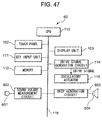
- FIG. 2 is a block diagram illustrating the hardware configuration of the PDA 10 shown in FIG. 1.
- the PDA 10 has a touch panel 102, a display unit 103, a key input unit 111, a memory 112, a CPU (central processing unit) 113, a drive signal generation circuit 114, and an oscillatory actuator 115.
- the touch panel 102 outputs a signal showing a touched position on the touch panel 102 (hereinafter called a "touch signal") to the CPU 113 in response to a touch operation.
- the display unit 103 has a liquid crystal display panel 103a and a drive circuit for controlling the display of the liquid crystal display panel 103a.
- the key input unit 111 outputs, to the CPU 113, a key operation signal in response to the pressing operation of the operation keys 104a to 104c by the user.
- the memory 112 stores programs, data, etc. for controlling the PDA 10. Further, the memory 112 stores waveform data of the drive signal for driving the oscillatory actuator 115.
- the CPU 113 executes a program stored in the memory 112 to control the parts of the device interconnected through a bus 116. This CPU 113 executes a vibration control processing 1 (see FIG. 5). Upon detection of an operation input from the touch panel 102 or any one of operation keys 104a to 104c, it drives the oscillatory actuator 115 through the drive signal generation circuit 114 to cause the touch panel 102 or one of the operation keys 104a to 104c to vibrate.
- the drive signal generation circuit 114 generates a drive signal for driving the oscillatory actuator 115 in accordance with waveform data supplied from the CPU 113. Further, the drive signal generation circuit 114 applies a drive signal to the oscillatory actuator 115 in accordance with instructions from the CPU 113.
- the oscillatory actuator 115 is a linear oscillatory actuator of a so-called moving permanent magnet type which uses a permanent magnet as a movable weight (weight) and causes the movable weight to linearly reciprocate by electromagnetic force to cause generation of vibration.
- the oscillatory actuator 115 is driven by a drive signal applied from the drive signal generation circuit 114 and generates vibration.
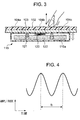
- FIG. 3 is a sectional view schematically illustrating a state of placement of the oscillatory actuator 115 in the main case 101 of the PDA 10.
- the top surface of the case 115a of the oscillatory actuator 115 is in contact with the liquid crystal display panel 103a and operation keys 104a to 104c.
- the case 115a of the oscillatory actuator 115 is provided inside it with a cylindrical coil 121 fixed to the top surface of the case 115a, a columnar movable weight 122 made of permanent magnet and having an annular space in which the coil 121 fits, and a spring 123 for supporting the movable weight 122.
- case 115a of the oscillatory actuator 115 is sealed and functions as a magnetic shield.
- the function as such a magnetic shield is given to the case 115a by, for example, forming the case 115a by a conductive substance and grounding it or making it the same potential.
- the case 115a may be made of a magnetic member having a high-permeability.
- the movable weight 122 is supported by the spring 123 in a state where the weight 122 is able to linearly reciprocate in the vertical direction in the figure in the space formed inside the case 115a of the oscillatory actuator 115.
- the spring 123 as shown in FIG. 3, is connected at one end to the case 115a (base member) that is in contact with the liquid crystal display panel 103a and operation keys 104a to 104c and is connected at its other end to the movable weight 122.
- a plurality of springs 123 may also be provided.
- the movable weight 122 linearly reciprocates in the vertical direction in the figure by the magnetic force generated from the coil 121 when an AC (alternating) current (drive signal) is applied to the coil 121.
- vibrational acceleration occurs at the portion of the case 115a to which the spring 123 is connected.
- the portion of the case 115a to which the spring 123 is connected receives a vibration component transmitted from the movable weight 122 through the spring 123 in addition to the counter force of the reciprocation along with the reciprocation of the movable weight 122.
- the principle of generation of vibration by the oscillatory actuator 115 is however based on the use of the vibrational acceleration occurring by a counter force of the reciprocation of the movable weight 122.
- vibration is transmitted to the liquid crystal display panel 103a and the operation keys 104a to 104c.
- the direction of the vibration is a direction perpendicular to the front surface of the touch panel 102 and matches with the direction by which the user presses the touch panel 102 or any one of the operation keys 104a to 104c and its opposite direction. Due to this, the touch panel 102 and the operation keys 104a to 104c vibrate in a direction perpendicular to the front surface of the touch panel 102 and vibration is transmitted to the fingertip of the user performing the operation input.
- the oscillatory actuator 115 shown in FIG. 3 is sealed by the case 115a having an anti-magnetic effect, but it is also possible that it not be sealed by this case 115a.
- the spring 123 supporting the movable weight 112 may also be connected directly to the rear surface of the liquid crystal display panel 103 rather than to the case 115a.
- an oscillatory actuator 115 integrally packaged in this way has the following advantages. That is, in the case of using an oscillatory actuator which is not integrally packaged, it is necessary to divide members of the oscillatory actuator into those to be placed at the rear surface of the liquid crystal display panel on which the touch panel is laid and those to be placed at the main body of the electronic device supporting the liquid crystal display panel. For example, it is necessary to place the permanent magnet at the rear surface of the liquid crystal display panel while placing the coil at a position facing the permanent magnet at the main body side of the electronic device.
- the support members of the electronic device supporting the liquid crystal display panel such as the main body and the case must be firmly fixed; alternatively, the mass of the support members have to be made sufficiently large compared with the liquid crystal display panel. Therefore, such a separate placement of the oscillatory actuator is not suitable for a light weight electronic device or portable electronic device.
- the movable weight 122 (permanent magnet) and the coil 121 are housed inside the case 115a in advance. Therefore, there is little possibility of causing the accuracy problem in mounting the permanent magnet and the coil. Further, compared with the separate placement, there is less probability of the mounting accuracy of the permanent magnet and the coil being deteriorated due to the aging. Thus, it is possible to cause the touch panel 102 to vibrate with a stable degree of accuracy. Further, it is sufficient to mount the integrally packaged oscillatory actuator 115 to a member desired to be caused to vibrate such as the rear surface of the liquid crystal display panel 103a. The process of the assembly work of the electronic device can therefore be simplified.
- the oscillatory actuator 115 gives the liquid crystal display panel 103a to which the movable weight 122 is connected the vibration occurring by a counter force of the reciprocation by causing reciprocation at the movable weight 122 supported in the air. Therefore, even when the support members of the PDA 10 such as the main body and the main case 101 are not firmly fixed or when the mass of the support member is not sufficiently large compared with the liquid crystal display panel 103a, the oscillatory actuator 115 can give a sufficiently large vibration to the liquid crystal display panel 103a etc. This is particularly suitable for use in a light weight electronic device or a portable electronic device.
- the case 115a of the oscillatory actuator 115 or the main case 101 of the PDA 10 at which the oscillatory actuator 115 is placed is caused to vibrate, thereby creating a sound in accordance with the audio signal. That is, it is also possible to use the oscillatory actuator 115 as a sound source. In this case, it is desirable to use the liquid crystal display panel 103a or the main case 101 etc., as a sound amplification mechanism, to which vibration generated by the oscillatory actuator 115 in accordance with application of the audio signal is transmitted, thereby increasing the volume of the sound generated at the oscillatory actuator 115.
- the oscillatory actuator 115 is used as both a vibration generator and a sound source in this way, it is possible to greatly reduce the space taken up by the components in compact electronic devices such as a mobile phone and a pager.
- the oscillatory actuator 115 as a sound source, it is possible to provide sound amplification mechanism such as a paper cone or horn at the inside or outside of the oscillatory actuator 115.
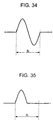
- FIG. 4 is a view illustrating a waveform of a drive signal applied to the oscillatory actuator 115.
- the frequency f 0 of the drive signal applied to the coil 121 of the oscillatory actuator 115 is made to match with the natural frequency f 1 of the main case 101 of the PDA 10 or the natural frequency f 2 of the oscillatory actuator 115 itself.
- Applying a drive signal of such a frequency f 0 to the coil 121 causes the main case 101 or the oscillatory actuator 115 of the PDA 10 to resonate, thereby imparting larger vibration to the user using small drive power. That is, it is possible to reduce the power consumption of the PDA 10.
- Such frequency data or amplitude data etc. is stored in the memory 112 as the waveform data of the drive signal.
- the frequency f 0 of the drive signal may also be set so that a frequency which is an integral multiple of the frequency f 0 corresponds to the natural frequency f 1 or natural frequency f 2 . It is possible to cause the main case 101 or the oscillatory actuator 115 of the PDA 10 to resonate even with such a frequency f 0 .
- the waveform of the drive signal is not limited to the SIN wave illustrated in FIG. 4 but may also be a square wave, trapezoidal wave, triangular wave, and the like.
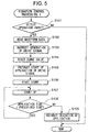
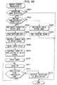
- FIG. 5 is a flow chart explaining the operation of a vibration control processing l'executed by the CPU 113 in the PDA 10 according to this embodiment.
- the vibration control processing 1 is executed by the CPU 113 at every predetermined period in a period where an operation input to the touch panel 102 or the operation keys 104a to 104c is permitted.
- the CPU 113 determines whether a touch signal has been input from the touch panel 102 and whether a key operation signal has been input from the key input unit 111 (step S101). When the CPU 113 determines that neither the touch signal nor key operation signal has been input, it ends the vibration control processing 1. On the other hand, when the CPU 113 determines that at least one of the touch signal or key operation signal has been input, it first reads from the memory 112 the waveform data of the drive signal to be applied to the oscillatory actuator 115 (step S102).
- the CPU 113 outputs the waveform data read from the memory 112 to the drive signal generation circuit 114.
- the CPU 113 instructs the drive signal generation circuit 114 to generate a drive signal (step S103).
- the drive signal generation circuit 114 generates a drive signal using the waveform data supplied from the CPU 113.
- the CPU 113 resets the count value for counting the time for the drive signal to be applied (step S104). Further, the CPU 113 instructs the drive signal generation circuit 114 to initiate applying the drive signal (step S105). At the same time, the CPU 113 starts counting the time for application (step S106).
- the drive signal generation circuit 114 applies the drive signal to the oscillatory actuator 115 for the period until the cessation of application is instructed by the CPU 113. Due to this, the oscillatory actuator 115 is driven and causes the touch panel 102 and the operation keys 104a to 104c vibrate in a direction perpendicular to the front surface of the touch panel 102.
- the CPU 113 increments the count value for counting the time of application in response to the start of counting of the time of application (step S107). Further, the CPU 113 determines whether the count has reached a count corresponding to a preset prescribed time (step S108). For example, in the present embodiment, the prescribed time is set to 0.5 second.
- the CPU 113 When the counted time of application is less than the prescribed time, the CPU 113 returns to step S107 and increments the time of application. In the case that it is determined that the time of application has exceeded the prescribed time, that is, when the counted time of application has reached 0.5 second, the CPU 113 instructs the drive signal generation circuit 114 to stop the application of the drive signal (step S109). The CPU 113 then ends the vibration control processing 1. When the cessation of application is instructed by the CPU 113, the drive signal generation circuit 114 stops applying the drive signal to the oscillatory actuator 115.
- the CPU 113 drives the oscillatory actuator 115 to cause the touch panel 102 or the operation keys 104a to 104c to vibrate. Therefore, the PDA 10 can report, to the user, that an operation input has been approved by way of vibration. As a result, the user can confirm if the operation input to the touch panel 102 or any one of the operation keys 104a to 104c has been approved by the PDA 10 without viewing the screen display.
- the oscillatory actuator 115 since a linear oscillatory actuator is used as the oscillatory actuator 115, the directional accuracy of vibration generated from the oscillatory actuator 115 is high. Therefore, by building the oscillatory actuator 115 into the PDA 10 so that the direction of vibration becomes perpendicular to the front surface of the touch panel 102 or the direction of depression of the operation keys 104a to 104c, it is possible to give the user by vibrational stimulus the feeling of pressing the touch buttons or operation keys when touching the touch panel 102 or when depressing thin operation keys 104a to 104c.
- the oscillatory actuator 115 by applying an audible band audio signal to the coil 121 of the oscillatory actuator 115, it is possible to use the oscillatory actuator 115 also as a sound source.
- the time of vibration may be set short such as 0.5 second.
- a "click” is the feeling of operation caused when pushing and releasing the button of a mouse when selecting an icon or button displayed on the screen of a display by operating the mouse.
- the time of vibration is preferably not more than one second at the maximum. Further, by making the vibration time short, it is possible to reduce the drive power of the oscillatory actuator 115 and reduce the power consumption of the PDA 10.
- the oscillatory actuator 115 houses the coil 121 and movable weight 122 inside the case 115a sealed to function as a magnetic shield. Therefore, the oscillatory actuator 115 is not affected by the magnetic force from the components of the PDA 10 provided around it. Further, the magnetic force generated from the coil 121 in the oscillatory actuator 115 does not affect the surrounding components.
- prevention of the magnetic force of the oscillatory actuator 115 from affecting the surrounding components is important in preventing malfunctioning of the surrounding components.
- the explanation was given of the case where the liquid crystal display panel 103a is used.
- the display of the CRT may be distorted in color or form due to the magnetic force generated from the oscillatory actuator.
- FIG. 6 is a block diagram illustrating the hardware configuration of a PDA 20 according to this embodiment.
- the PDA 20 has a touch panel 102, a display unit 103, a key input unit 111, a memory 112, a CPU 113, a drive signal generation circuit 211, a vibrator 212, and an encoder 213.
- the memory 112 stores waveform data of a drive voltage for driving the vibrator 212.
- the CPU 113 executes a vibration control processing 2 (see FIG. 11). In the case of detecting operation input from the touch panel 102 or any one of the operation keys 104a to 104c, the CPU 113 drives the vibrator 212 through the drive signal generation circuit 211 to cause the touch panel 102 or one of the operation keys 104a to 104c to vibrate. Further, the CPU 113 determines the timing for stopping the application of the drive signal to the vibrator 212 on the basis of rotational angle information supplied from the encoder 213.
- the drive signal generation circuit 211 generates a drive signal for driving the vibrator 212 in accordance with the waveform data supplied from the CPU 113. Further, the drive signal generation circuit 211 applies the drive signal to the vibrator 212 in accordance with an instruction from the CPU 113.
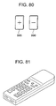
- the vibrator 212 is a DC motor having an eccentric weight attached to its shaft. The vibrator 212 is driven by a drive signal applied from the drive signal generation circuit 211 and generates vibration.
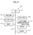
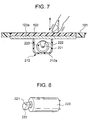
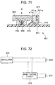
- FIG. 7 is a sectional view schematically illustrating how the vibrator 212 is placed in the main case 101 of the PDA 20.
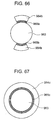
- FIG. 8 is a perspective view illustrating the appearance of the vibrator 212.
- the vibrator 212 housed in a case 212a is placed at the bottom surface of the liquid crystal display panel 103a. This vibrator 212 is fixed inside the case 212a by a support member (not shown).
- the vibrator 212 is configured by a DC motor 223 having an eccentric weight 222 attached to an end of a shaft 221.
- the eccentric weight 222 attached to the shaft 221 rotates, and the rotational movement of the eccentric weight 222 causes vibration at the case 212a.
- the direction or mode of vibration generated from the vibrator 212 varies depending on the initial position of the eccentric weight 222 or the rotational direction of the DC motor 223. To cause the same vibration to be generated by the vibrator 212 every time, it is necessary to detect the position of the eccentric weight 222 and cause the eccentric weight 222 to rotate from the same position in the same direction at all times.
- the PDA 20 is provided with the encoder 213.
- This encoder 213 detects the rotational angle information of the DC motor 223 and outputs it to the CPU 113.
- the CPU 113 determines the timing for stopping the application of the drive voltage to the DC motor 223 on the basis of the rotational angle information supplied from the encoder 213.
- the timing of cessation of application of the drive voltage to the DC motor 223 is determined so that the eccentric weight 222 stops at the position of exactly 12:00 when centered about the shaft 221. Note that when using a stepping motor instead of the DC motor 223, it is possible to detect the position of the eccentric weight attached to the shaft without using the encoder 213.
- the direction of vibration generated from the vibrator 212 matches the direction perpendicular to the front surface of the touch panel 102.
- the vibration generated from the vibrator 212 is transmitted to the touch panel 102 through the liquid crystal display panel 103a. Due to this, the touch panel 102 vibrates in a direction perpendicular to its front surface and this vibration is transmitted to the fingertip of the user operating the touch panel 102.
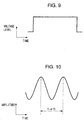
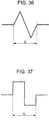
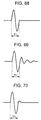
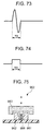
- FIG. 9 is a view illustrating a waveform of a drive voltage applied to the vibrator 212.
- FIG. 10 is a view illustrating vibration occurring at the front surface of the touch panel 102.
- the rotational speed of the DC motor 223 changes in accordance with the drive voltage applied.
- the main case 101 of the PDA 20 or the vibrator 212 resonates.
- drive voltage is applied to the vibrator 212 so as to make the rotational speed of the DC motor 223 match with the natural frequency f 1 or natural frequency f 3 . Therefore, as shown in FIG. 10, the touch panel 102 vibrates in a direction perpendicular to the front surface by a period of the natural frequency f 1 or natural frequency f 3 . Due to this, it becomes possible to give a larger vibration by a small drive power and the power consumption of the PDA 20 can be reduced. Note that the waveform of the drive voltage is not limited to the square waveform illustrated in FIG. 9.
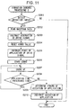
- FIG. 11 is a flow chart for explaining the operation of the vibration control processing 2, in the PDA 20 according to this embodiment, the processing 2 being executed by the CPU 113.
- the vibration control processing 2 is executed by the CPU 113 at every predetermined period in a period during which operation input to the touch panel 102 or the operation keys 104a to 104c is permitted. Note that the processing shown in steps S201 to S208 of the second vibration control processing is similar to the processing of steps S101 to S108 of the vibration control processing 1 (see FIG. 5) explained in the first embodiment, so explanations thereof will be omitted.
- the drive signal generated in the drive signal generation circuit 211 becomes the drive voltage shown in FIG. 9.
- the vibrator 212 causes the DC motor 223 to rotate at a rotational speed corresponding to the natural frequency f 1 of the main case 101 or the natural frequency f 3 of the vibrator 212.
- the eccentric weight 222 rotates and causes vibration.
- the vibration generated by the vibrator 212 causes the touch panel 102 and the operation keys 104a to 104c to vibrate in a direction perpendicular to the front surface of the touch panel 102.
- step S208 in the case that the CPU 113 determines that the time of application has exceeded a prescribed time, that is, when the time of application has reached 0.5 second, the CPU 113 proceeds to step S209.
- the CPU 113 determines the timing for stopping the application of the drive voltage to cause the eccentric weight 222 to stop each time at the same position on the basis of the rotational angle information supplied from the encoder 213 (step S209).
- the timing of cessation of application of the drive voltage is determined so that the eccentric weight 222 stops at the position of exactly 12:00 when centered on the shaft 221.
- the CPU 113 instructs the drive signal generation circuit 221 to stop the application of the drive signal in accordance with the determined timing of cessation of application (step S210).
- the CPU 113 ends the vibration control processing.
- the drive signal generation circuit 221 stops the application of the drive signal to the vibrator 212.
- the eccentric weight 222 attached to the DC motor 223 of the vibrator 212 stops at the same position each time.
- the eccentric weight 222 is made to stop at the same position at all times and weight to rotate from the same stopped position in the same direction in this way thereby enabling to fix the direction of vibration generated by the vibrator 212. Further, the vibration generated by the vibrator 212 can be closely controlled.
- the CPU 113 drives the vibrator 212 to cause the touch panel 102 or one of the operation keys 104a to 104c to vibrate. Therefore, the PDA 20 can report to the user by vibration that an operation input has been approved.
- the eccentric weight 222 is made to stop at the same position at all times and rotation is started in the same direction from the stopped position. Due to this, it is possible to fix the direction of vibration generated by the vibrator 212 and to closely control the vibration generated by the vibrator 212. As a result, the user is provided with a pressing feeling or a "click” feeling of the touch buttons or the operation keys by vibrational stimulus when a touching operation to the touch panel 102 or a pressing operation to the thin operation keys 104a to 104c is performed. Imparting this pressing feeling or "click” feeling requires control of the stopping position of the eccentric weight 222 explained above and was not possible with the conventional eccentric weight motor.
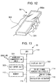
- FIG. 12 is a perspective view illustrating the appearance of a PDA 30 according to this embodiment.
- the PDA 30 is provided with a display screen of a liquid crystal display panel 302a covering an opening of the main case 301.
- the top surface of the main case 301 is provided with a key input unit 303 having a plurality of push-button type operation keys.
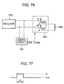
- FIG. 13 is a block diagram illustrating the hardware configuration of the PDA 30 shown in FIG. 12.
- the PDA 30 has a display unit 302, a key input unit 303, a wireless communication unit 304, a memory 112, a CPU 113, a drive signal generation circuit 114, and an oscillatory actuator 115.
- the PDA 30 has the function for performing data communication with other communications devices through networks such as WAN (wide area network) and LAN (local area network).
- the wireless communication unit 304 controls wireless communication performed with a wireless base station of the WAN or LAN.
- the CPU 113 executes the vibration control processing 3(see FIG. 14) and, in the case of detecting the completion of a processing instructed by an operation input, drives the oscillatory actuator 115 through the drive signal generation circuit 114 to cause the main case 301 to vibrate.
- the oscillatory actuator 115 is the same as the oscillatory actuator 115 explained in the first embodiment. In the present embodiment, however, the oscillatory actuator 115 is attached to the back surface of the PDA 30, that is, the inside of the main case 301 on the side opposite the back of the surface on which the display screen is provided, and causes the main case 301 to vibrate. Further, the vibration is transmitted to the hand of the user holding the PDA 30.
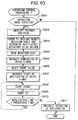
- FIG. 14 is a flow chart for explaining the operation of a vibration control processing 3 executed by the CPU 113 in the PDA 30 according to this embodiment.
- the vibration control processing 3 is executed when the processing requiring a waiting time is instructed by operation input.
- processing requiring a waiting time means, for example, file data downloading or uploading processing such as reading a web page, mail check processing for checking for e-mail addressed to oneself, start-up processing for starting up an application software, copying or deletion of file data, initialization processing for initializing a data storage area of the memory 112, and the like.
- step S301 the CPU 113 executes the processing instructed by operation input (step S301).
- step S302 the CPU 113 determines whether the processing being executed has been completed (step S302).
- step S302 the processing being executed has been completed
- the CPU 113 proceeds to step S303.
- the processing from step S303 is similar to the processing from step S102 of the vibration control processing 1 (see FIG. 5) explained in the first embodiment, so explanations thereof will be omitted.
- the CPU 113 drives the oscillatory actuator 115 through the drive signal generation circuit 114 to cause the main case 301 of the PDA 30 to vibrate. As a result, the vibration is transmitted to the hand of the user holding the PDA 30.
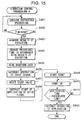
- FIG. 15 is a flow chart for explaining the operation of a vibration control processing 4 executed by the CPU 113 in the PDA 30 according to this embodiment. As shown in the figure, first, the CPU 113 executes the processing instructed by the operation input (step S4301). Next, when determining that the processing being executed has ended (step S402), the CPU 113 proceeds to step S403.
- the CPU 113 acquires the result of execution of the processing executed at step S401 (step S403).
- the CPU 113 changes the time of application of the drive signal, that is, the count value of the prescribed time specifying the time of application, in accordance with the results of execution (step S404). For example, when mail check processing has been executed, the CPU 113 leaves the prescribed time as 0.5 second when the result of the check is that there is no e-mail addressed to itself. Further, it changes the prescribed time to 1.5 seconds when there is e-mail addressed to itself.
- step S405 is similar to the processing from step S303 of the vibration control processing 3 (see FIG. 14), so a detailed explanation will be omitted, but the CPU 113 changes the time of vibration of the main case 301 according to the results of execution of the processing.
- the CPU 113 drives the oscillatory actuator 115 to cause the main case 301 of the PDA 30 to vibrate. Therefore, the PDA 30 can report to the user the completion of processing instructed by operation input by vibration. Further, according to the present embodiment, the CPU 113 changes the time of vibration of the oscillatory actuator 115 in accordance with the results of execution of the processing. Therefore, the user can confirm the results of execution of the instructed processing on the basis of vibration time even without viewing the screen information.
- the explanation was given of the case of changing the time of vibration in accordance with the results of execution of the processing, but it is also possible to change the magnitude of the vibration, the number of vibrations, etc.
- the point is to change the mode of vibration generated from the oscillatory actuator 115 in accordance with the results of execution of the processing.
- the entire main case 301 of the PDA 30 was made to vibrate. It is however also possible to make only the portion of the main case 301 held by the user when holding the PDA 30 vibrate.
- FIG. 16 is a view illustrating an internal structure of a PDA 40 according to this embodiment.
- the PDA 40 has a liquid crystal display panel 103a over which a touch panel 102 is laid.
- the display screen of the liquid crystal display panel 103a covers the opening of the main case 401.
- the rear surface of the liquid crystal display panel 103a is provided with an oscillatory actuator 115a. This oscillatory actuator 115a causes the touch panel 102 to vibrate to transmit vibration to the fingertip of the user performing the operation input.
- an oscillatory actuator 115b is provided at the inside of the main case 401 at the back surface side of the PDA 40, that is, the side opposite to the surface where the display screen is provided.
- This oscillatory actuator 115b gives vibration to the palm of the hand of the user holding the PDA 40 through the main case 401.
- the oscillatory actuators 115a and 115b are the same as the oscillatory actuator 115 explained in the first embodiment.
- a push-button type operation key 104a for inputting an on/off operation of the main power is provided at the side surface of the main case 401.
- the PDA 40 has two oscillatory actuators 115a and 115b. Further, while not shown in FIG. 16, the PDA 40 has a touch sensor and drives one of the oscillatory actuators to generate vibration in accordance with whether the PDA 40 is being held by the user. The reason for this control is to prevent, when the main case 401 of a PDA 40 placed on a desktop is vibrated, the PDA 40 from moving due to this vibration or striking the desk at the time of vibration and therefore causing an unpleasant buzzing sound.
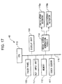
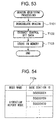
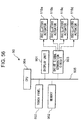
- FIG. 17 is a block diagram illustrating the hardware configuration of the PDA 40 shown in FIG. 16.
- the PDA 40 has a touch panel 102, a display unit 103, a key input unit 111, a memory 112, a CPU 113, a drive signal generation circuit 114, oscillatory actuators 115a and 115b, and a touch sensor 411.
- the touch sensor 411 is a sensor for detecting if the PDA 40 is being held by a user and supplies the results of detection to the CPU 113.
- the memory 112 stores waveform data of the drive signals to be applied to the oscillatory actuators 115a and 115b.
- the frequency of the drive signal applied to the oscillatory actuator 115a corresponds to the frequency for causing the liquid crystal display panel 103 provided with the touch panel 102 to resonate or the frequency for causing the oscillatory actuator 115a itself to resonate.
- the frequency of the drive signal applied to the oscillatory actuator 115b corresponds to the frequency for causing the main case 401 of the PDA 40 to resonate or the frequency for causing the oscillatory actuator 115b itself to resonate.
- the CPU 113 executes a vibration control processing 5 (see FIG. 18) and reports to the user by vibration that a touch operation on the touch panel 102 has been received. In the present embodiment, however, the CPU 113 drives only one of the two oscillatory actuators 115a and 115b to generate vibration in accordance with the results of detection of the touch sensor 411.
- the drive signal generation circuit 114 generates drive signals for driving the oscillatory actuators 115a and 115b in accordance with waveform data supplied from the CPU 113. Further, the drive signal generation circuit 114 applies drive signals to the oscillatory actuators 115a and 115b in accordance with instructions from the CPU 113.
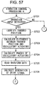
- FIG. 18 is a flow chart for explaining the operation of the vibration control processing 5 executed by the CPU 113 in the PDA 40 according to this embodiment.
- the vibration control processing 5 is executed by the CPU 113 every predetermined period in the period where a touch operation on the touch panel 102 is permitted.
- the CPU 113 determines whether a touch signal has been input from the touch panel 102 (step S501). When it is determined that a touch signal has not been input, the CPU 113 ends the vibration control processing 5. Note that even when the CPU 113 determines that a touch signal has been input from the touch panel 102, when it detects that a touched position of the touch panel 102 based on the signal is outside of the display areas of the touch buttons displayed on the display screen, the routine does not proceed to the processing of step S502 and the vibration control processing 5.
- the CPU 113 next determines whether the PDA 40 is being held by the user based on the results of detection of the touch sensor 411 (step S502). Further, when it is determined that the PDA 40 is being held by. the user, the CPU 113 determines the oscillatory actuator 115b as the oscillatory actuator to be driven (step S503). That is, when the PDA 40 is being held by the user, the handheld portion of the main case 401 is made to vibrate to transmit vibration to the palm of the hand of the user holding the PDA 40.
- the CPU 113 determines the oscillatory actuator 115a as the oscillatory actuator to be driven (step S504). That is, when the PDA 40 is not being held by the user, the touch panel 102 is made to vibrate to transmit vibration to the fingertip of the user performing the touch operation.
- step S505 is similar to the processing in step S102 and the following steps of the vibration control processing 1 explained in the first embodiment (see FIG. 5), so a detailed explanation will be omitted; but in this embodiment the CPU 113 drives the oscillatory actuator determined by the processing of step S503 or S504 to give vibration to the touch panel 102 or the handheld portion of the main case 401.
- the CPU 113 drives one of the oscillatory actuators to cause the generation of vibration in accordance with results of detection of the touch sensor 411. Therefore, in the PDA 40, the location of vibration can be switched to the touch panel 102 or the handheld portion of the main case 401 depending on whether the PDA 40 is being held by the user.
- the oscillatory actuator used for a report by vibration may also be designated by the user.
- the CPU 113 gives a screen display for prompting the user to designate one or more oscillatory actuators for use when performing report by vibration.
- the CPU 113 stores that designation information in the memory 112. Further, after it is determined that a touch signal has been input from the touch panel 102 at step S501, the CPU 113 determines the oscillatory actuator to be driven in accordance with the designation information stored in the memory 112.
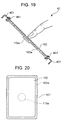
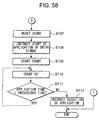
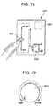
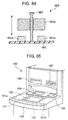
- FIG. 19 is a section view illustrating an internal structure of the PDA 41 according to a modification of this embodiment.
- a liquid crystal display panel 103a having the touch panel 102 placed over the display surface and having the oscillatory actuator 115a placed over its rear surface is attached to the main case 401 of the PDA 41 through an elastic member 451.
- This elastic member 451 is for example rubber, urethane, sponge, etc. and, as shown in FIG. 20, is attached to the periphery of the liquid crystal display panel 103a.
- This elastic member 451 is a member for causing the touch panel 102 and the liquid crystal display panel 103a to efficiently vibrate.
- the elastic member 451 may also be placed in a plurality of pieces at the periphery of the liquid crystal display panel 103a. Further, the elastic member 451 may also be configured using a spring and the like.
- the touch panel 102 and the liquid crystal display panel 103a are attached to the main case 401 through the elastic members 451, 451a to 451f shown in FIG. 20 to FIG. 22, thereby enabling the effective transmission of the vibration generated by the oscillatory actuators 115a and 115b to the touch panel 102 and the liquid crystal display panel 103a. In other words, it is possible to give a larger vibration to the user while keeping down the drive power of the oscillatory actuator 115a.
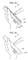
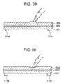
- the oscillatory actuator 115b may be placed partially exposed from the opening provided in the main case 401a and to give vibration directly to the palm of the hand of the user holding the PDA 43. Even in the case of this configuration, it is possible to efficiently transmit the vibration generated by the oscillatory actuator 115 to the user. In this case, since the oscillatory actuator 115b can directly give vibration to the user, vibration can be closely controlled.
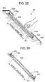
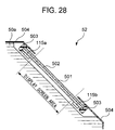
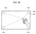
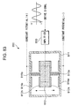
- FIG. 25 is a sectional view for explaining the internal structure of an ATM 50 according to the present invention.
- a liquid crystal display panel 501 is placed at an incline on the front surface of the main body 50a of the ATM 50.
- a touch panel 502 is attached to the display surface of the liquid crystal display panel 501 through a damper 503.
- This touch panel 502 is provided with two oscillatory actuators 115a and 115b above and below the touch surface.
- a main cover 504 having an opening is provided further outside from the touch panel 502.
- the touch panel 502 is configured by a transparent, hard member such as a glass plate.
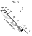
- the damper 503 is a vibration absorbing member made of rubber, urethane, sponge, and the like, and attached to the periphery of the touch panel 502.
- the damper 503 absorbs the vibration component transferred to the liquid crystal display panel 501 out of the vibration generated by the oscillatory actuators 115a and 115b placed on the touch panel 502 and prevents the vibration from being transmitted to the liquid crystal display panel 501.
- the damper 503 performs the role of causing the touch panel 502 placed on the liquid crystal display panel 501 to efficiently vibrate. Therefore, the damper 503 is preferably configured by an elastic body such as rubber.
- the oscillatory actuators 115a and 115b are the same as the oscillatory actuator 115 explained in the first embodiment. Further, the damper 503 and the oscillatory actuators 115a and 115b are provided at the outside of the display screen area of the liquid crystal display panel 501.
- the liquid crystal display panel 501 is fixed to the main body 50a of the ATM 50.
- the touch panel 502 is attached to the liquid crystal display panel 501 through only the damper 503.
- a clearance is provided between the touch panel 502 and the main cover 504. Therefore, the touch panel 502 vibrates in a direction perpendicular to the front surface of the touch panel 502 due to the vibration generated by the oscillatory actuators 115a and 115b.
- control for causing generation of vibration from the oscillatory actuators 115a and 115b in response to a touch operation on the touch panel 502, control may be performed in the same way as the vibration control processing 1 explained in the first embodiment (see FIG. 5) except for that the oscillatory actuators 115a and 115b are plural; so an explanation thereof will be omitted.
- the frequencies of the drive signals applied to the oscillatory actuators 115a and 115b are set to frequencies for causing the touch panel 502 to resonate or frequencies for causing the oscillatory actuators 115a and 115b themselves to resonate.
- the ATM 50 can make only the touch panel 502 vibrate by vibration generated from the oscillatory actuators 115a and 115b.
- the vibration to the liquid crystal display panel 501 is absorbed by the damper 503. Therefore, the content of the screen display of the liquid crystal display panel 501 does not flicker, so the displayed content is easy to view compared with a case causing the liquid crystal display panel and the touch panel to vibrate as in the first embodiment.
- FIG. 27 is a sectional view for explaining an internal structure of an ATM 51 according to a modification of this embodiment.
- the touch panel 502 is attached through two oscillatory actuators 115a and 115b to the display surface of the liquid crystal display panel 501 placed at an incline on the front surface side of the main body 50a of the ATM 51.
- the liquid crystal display panel 501 is fixed to the main body 50a of the ATM 51.
- the touch panel 502 is attached to the liquid crystal display panel 501 through only the oscillatory actuators 115a and 115b.
- a clearance is provided between the touch panel 502 and the main cover 504. Therefore, the touch panel 502 vibrates in a direction perpendicular to the front surface of the touch panel 502 by the vibration generated by the oscillatory actuators 115a and 115b.
- the liquid crystal display panel 501 is fixed to the main body 50a, it does not vibrate much at all even though it contacts the oscillatory actuators 115a and 115b. Therefore, the structure shown in FIG. 27 enables similar effects to be obtained as in the case of the structure shown in FIG. 25.
- FIG. 28 to FIG. 31 are sectional views illustrating internal structures of ATMs 52, 53, 54, and 55 according to other modifications of this embodiment.
- a liquid crystal display panel 501 to the main cover 504 through a damper 503, the liquid crystal display panel having the touch panel 502 laid over its display surface and having oscillatory actuators 115a and 115b placed at its rear surface.
- a clearance is provided between the liquid crystal display panel 501 and main body 50a of the ATM 52.
- the damper 503 in this modification performs the function of causing the touch panel 502 and liquid crystal display panel 501 to efficiently vibrate.
- the liquid crystal display panel 501 to the main body 50a of the ATM 54 through the damper 503, the liquid crystal display panel 501 having the touch panel 502 laid on its display surface and having the oscillatory actuators 115a and 115b placed at its rear surface.
- a clearance is provided between the liquid crystal display panel 501 and the main cover 504.
- the explanation was made of the case of employing a liquid crystal display as the display.
- the display may also be a CRT, plasma display, or an EL (electronic luminescence) display, etc.
- the number of the oscillatory actuators 115a and 115b may be any number.
- the damper 503 may also be configured using a spring and the like.
- FIG. 32 is a view of an example of the screen display of the PDA 10 according to a first example of present embodiment.
- the display screen of the PDA 10 shows a plurality of touch buttons "A" to "G".
- the touch panel 102 overlaid on the display screen detects a touch operation when a user touches a displayed touch button by his or her fingertip. Note that the letters assigned to the touch buttons are only given for identifying the touch buttons.
- FIG. 33 is a view illustrating a waveform data table 112a stored in the memory 112 in the PDA 10.
- the waveform data table 112a stores, for each touch button displayed on the screen, area data showing the area occupied by a touch button on the touch panel 102 using XY coordinates as well as waveform data of the drive signal to be applied to the oscillatory actuator 115 when that touch button is pressed.
- the waveform of the drive signal linked with each touch button differs in amplitude or shape as illustrated in FIG. 34 to FIG. 37.
- the frequency f 0 of the drive signal is a frequency causing any one of the main case 101 of the PDA 10, the liquid crystal display panel 103a provided with the touch panel 102, and the oscillatory actuator 115 to resonate.
- the above-mentioned waveform data table 112a stores the frequency data, amplitude data, and the like required for generating these drive signals as the waveform data.
- the touch panel 102 When a user touches the touch panel 102 of the PDA 10 having this configuration with his or her fingertip, the touch panel 102 detects that touch operation and outputs a touch signal to the CPU 113.
- the CPU 113 finds the XY coordinate data of a touched position based on the touch signal, refers to the waveform data table 112a, and identifies the pressed touch button. Next, the CPU 113 reads from the waveform data table 112a the waveform data of the drive signal linked with the identified touch button.
- the CPU 113 outputs the read waveform data to the drive signal generation circuit 114.
- the CPU 113 instructs the generation of the drive signal to the drive signal generation circuit 114.
- the rest of the processing is similar to the processing in step S103 and the following steps of the vibration control processing 1 explained in the first embodiment (see FIG. 5), so an explanation thereof will be omitted.
- the CPU 113 in the case of detecting a touch operation on the touch panel 102, the CPU 113 first detects a touched position and identifies the operated touch button. The CPU 113 then causes vibration to be generated from the oscillatory actuator 115 by a vibration mode linked with the type of the touch button. Therefore, the PDA 10 can change the mode of vibration reporting that a touch operation has been approved in accordance with the operated touch button.
- vibration showing that the touch operation was invalid may also be generated from the oscillatory actuator 115. Further, it is also possible to change the vibration mode such as changing the vibration time, the number of vibrations, or the like.
- the invention according to the first example of the present embodiment can also be applied to an electronic device having a plurality of operation keys instead of the touch panel 102.
- the memory stores the waveform data for each operation key.
- the operating unit of the electronic device reads out the waveform data for the operated key from the memory to drive the vibration generator.
- FIG. 38 and FIG. 39 are views illustrating the state where a user is dragging an icon displayed on the display screen of the PDA 10 by a touch operation on the touch panel 102 to transfer it to the "trash". Note that the "trash” spoken of here is an icon for instructing deletion of data.
- the CPU 113 of the PDA 10 detects the touched position and identifies the touch operation as an instruction for the selection of the icon.
- the memory 112 of the PDA 10 stores the waveform data table 112b, as shown in FIG. 40, storing the waveform data of the drive signal to be applied to the oscillatory actuator 115 for each type of instruction designated by an operation input.
- the CPU 113 reads the waveform data linked with "SELECT ICON" from the waveform data table 112b and drives the oscillatory actuator 115. As a result, the fingertip of the user performing the touch operation or the hand of the user holding the PDA 10 is given vibration indicating that the icon is selected.
- the CPU 113 identifies the touch operation as an instruction for the dragging of the icon. Therefore, the CPU 113 reads the waveform data linked with "DRAG" from the waveform data table 112b and drives the oscillatory actuator 115. Due to this, vibration showing that a drag operation is under way is transmitted to the user. For example, when a drag operation is under way, it is preferable to continuously give a weak vibration.
- the CPU 113 identifies the touch operation as instruction for the placement of the icon in the trash. Therefore, while the CPU 113 stores the icon in the trash, it reads the waveform data linked with "DELETE DATA" from the waveform data table 112b and drives the oscillatory actuator 115. As a result, the user performing the touch operation is given vibration indicating deletion of the icon.
- the CPU 113 in the case of detecting a touch operation on the touch panel 102, the CPU 113 first identifies the type of the instruction designated by the touch operation. Further, the CPU 113 causes the oscillatory actuator 115 to generate vibration by a mode of vibration linked with the type of the identified instruction. Thus, the PDA 10 can change the mode of vibration for reporting that the touch operation has been received in accordance with the type of instruction designated by the touch operation.
- FIG. 41 is a view of an example of the screen display of a PDA 10 according to a third example of this embodiment.
- the display screen of the PDA 10 displays a "scale” and "knob” for adjusting the value of a parameter such as the level of sound of the PDA 10 or the brightness of the screen.
- the user can drag and change the position of the "knob" displayed on the screen by a touch operation on the touch panel 102.
- the CPU 113 of the PDA 10 recognizes that the "knob” has been clicked. Further, the CPU 113 gives the user vibration showing that the "knob” has been clicked.
- the memory 112 of the PDA 10 stores the waveform data table 112c shown in FIG. 42.
- This waveform data table 112c divides the range of values which the parameter can take into several sections and stores waveform data of the drive signal to be applied to the oscillatory actuator 115 for each section.
- the CPU 113 obtains the value of the parameter in accordance with the position of the dragged "knob”, reads the waveform data linked with the current value of the parameter from the waveform data table 112c, and drives the oscillatory actuator 115. Therefore, while the "knob" is being dragged, the fingertip of the user performing the touch operation or the hand of the user holding the PDA 10 is given vibration in accordance with the value of the parameter.
- the waveform data sets of the drive signals for the case where the value of the parameter is "0" (FIG. 43), for the case where the value of the parameter is "50" (FIG. 44), and the case where the value of the parameter is "100" (FIG. 45) are stored in the memory 112.
- the CPU 113 When the current value of the parameter is "40", the CPU 113 synthesizes two waveforms in the ratio of the waveform of the value of a parameter "0" to the waveform of the value of a parameter "50” as 1 to 4. Further, the CPU 113 applies the synthesized waveform to the oscillatory actuator 115 as the drive signal.
- the CPU 113 causes the oscillatory actuator 115 to generate vibration in the mode of vibration linked with the value of the parameter changed by the touch operation.
- the PDA 10 can change the mode of vibration for reporting that a touch operation has been received according to the value of the parameter changed by this touch operation.
- the aspect of the invention according to the third example of the present embodiment can also be applied to an electronic device having an operating member for changing seamlessly a variable value of the parameter (for example a slider switch 993 illustrated in FIG. 78, a dial type switch 994 illustrated in FIG. 79, etc.).
- the operating unit of the electronic device in the case of detecting that the operating member has been operated, causes the vibration generator to generate vibration in a mode of vibration linked with the value of the parameter changed by the operation of the operating member.
- the mode of vibration for reporting that operation of the operating member has been received by the electronic device can be changed in accordance with the value of the parameter changed by operation of the operating member.
- the touch panel of the PDA 10 can detect two operating states, that is, the state where the fingertip of the user is in contact with the touch panel (hereinafter, in this embodiment, called a "touch operation”) and the state where the fingertip is pressing the touch panel by a force of more than a predetermined level of pressure (hereinafter, in this embodiment, called a "pressing operation").
- the type of touch signal output from the touch panel to the CPU 113 differs from the case of a touch operation to the case of a pressing operation.
- the memory 112 of the PDA 10 stores the waveform data table 112d shown in FIG. 46.
- the waveform data table 112d corresponds to the example of the screen display of the touch buttons shown in FIG. 32.
- the waveform data table 112d stores for each touch button the area data for the touch button and the waveform data to be applied to the oscillatory actuator 115 for each of the cases when the touch button is subjected to a touch operation and when it is subjected to a pressing operation.
- a touch operation when a touch operation is performed on the touch panel, the touch panel outputs to the CPU 113 a touch signal showing that a touch operation has been performed.
- the CPU 113 finds the coordinate data of the touched position based on the touch signal and identifies the touch button operated referring to the waveform data table 112d.
- the CPU 113 reads the waveform data for the touch operation linked with the identified touch button from the waveform data table 112d.
- the CPU 113 drives the oscillatory actuator 115 using the drive signal generated by the read waveform data.
- the same is true for the case when a pressing operation is performed on the touch panel.
- the CPU 113 reads the waveform data for the pressing operation linked with the operated touch button from the waveform data table 112d and drives the oscillatory actuator 115.
- the PDA 10 transmits to the user vibration for the touch operation linked with the type of touch button contacted by the fingertip. That is, in the state where the user is searching the position of a touch button, for example, a weak vibration that differs for each type of touch button is transmitted to the user.
- the PDA 10 transmits to the user vibration for the pressing operation linked with the type of the touch button. That is, when the user presses against a touch button, vibration showing that the operation has been received is given to the user.
- Such control for the report by vibration is particularly effective when the visual confirmation of operation input is difficult. For example, it is effective when applied to a car navigation system. Further, even in a general electronic device, it is effective when performing operation input by touch at night in a state where there is no light.
- the CPU 113 causes the oscillatory actuator 115 to generate vibration by a mode of vibration differs for the case of a touch operation to the case of a pressing operation. Therefore, the PDA 10 can change the mode of vibration for reporting that an operation input has been received in accordance with the method of operation input to the touch panel.
- a touch panel for receiving as operation input the state of the fingertip of the user in contact with the touch panel and a touch panel for receiving as operation input pressure of more than a predetermined level of pressure by the fingertip of the user.
- the number of such combined touch panels is not limited to two.
- FIG. 47 is a block diagram illustrating the hardware configuration of a PDA 60.
- the PDA 60 has a touch panel 102, a display unit 103, a key input unit 111, a memory 112, a CPU 113, a drive signal generation circuit 114, an oscillatory actuator 115, a microphone 601, a sound volume measurement circuit 602, a beep generation circuit 603, and a speaker 604.
- the sound volume measurement circuit 602 measures the level of sound based on the analog signal waveform of the surrounding sound of the PDA 60 obtained from the microphone 601 and outputs the result of measurement to the CPU 113.
- the beep generation circuit 603 generates a drive signal to be applied to the speaker 604 in accordance with an instruction from the CPU 113. The drive signal is applied to the speaker 604 and a beep is generated.
- the PDA 60 has an audio report mode which reports that an operation input has been received by a beeping sound and a vibration report mode which reports that an operation input has been received by vibration.
- the CPU 113 executes a report control processing 1 (see FIG. 48) and reports to the user by a beeping sound or vibration that a touch operation to the touch panel 102 has been received. At this time, the CPU 113 switches the report mode to the audio report mode or the vibration report mode in accordance with the results of measurement by the sound volume measurement circuit 602.
- the switching control of the report mode is performed because at a noise of more than a certain level such as in the street, a report by a beeping sound is little effective.
- the CPU 113 determines that the surrounding volume of the PDA 60 is more than a preset level of sound, it selects at least the vibration report mode.
- FIG. 48 is a flow chart for explaining the operation of the report control processing 1 executed by the CPU 113 in a PDA 60 according to this embodiment.
- This report control processing 1 is executed by the CPU 113 at every predetermined period in a period in which a touch operation on the touch panel 102 is permitted.
- the CPU 113 determines whether a touch signal has been input from the touch panel 102 (step S601).
- the CPU 113 ends the report control processing 1 when it is determined that a touch signal has not been input.
- the CPU 113 determines whether the sound volume of the surroundings of the PDA 60 is higher than a preset level of sound based on the results measured by the sound volume measurement circuit 602 (step S602).
- the CPU 113 determines the audio report mode as the report mode (step S603).
- the CPU 113 drives the beep generation circuit 603 to produce the beeping sound from the speaker 605 (step S604) and reports that a touch operation has been received by a beeping sound to the user.
- step S602 when judging in step S602 that the sound volume in the surroundings of the PDA 60 is more than the preset level of sound, the CPU 113 determines the vibration report mode as the report mode (step S605). Further, the CPU 113 drives the oscillatory actuator 115 through the drive signal generation circuit 114 to report that the touch operation has been received to the user by vibration. Note that the processing in step S606 and the following steps is similar to the processing in step S102 and the following steps of the vibration control processing 1 explained in the first embodiment (see FIG. 5), so an explanation thereof will be omitted.
- the CPU 113 switches the report mode for reporting that a touch operation has been received to the audio report mode or the vibration report mode based on the measurement results obtained from the sound volume measurement circuit 602. Therefore, at the PDA 60 it can be automatically selected whether to report by vibration or whether to report by a beeping sound in accordance with the sound volume (noise level) of the surroundings.
- the report mode may also be so configured as to be designated by the user.
- the CPU 113 displays a screen for prompting the user to designate the report mode to be used.
- the CPU 113 stores designation information in the memory 112 when one or more of the audio report mode or vibration report mode is selected by operation input from the user. Further, when the CPU 113 determines that a touch signal has been input from the touch panel 102 at step S601, it sets the report mode to at least one of the audio report mode or vibration report mode in accordance with the designation information stored in the memory 112.
- the oscillatory actuator 115 by applying an audible band audio signal to the coil 121 of the oscillatory actuator 115, it is possible to use the oscillatory actuator 115 as a speaker 604 (sound source).
- the waveform of the drive signal for causing the generation of vibration from the oscillatory actuator 115 is as shown for example in FIG. 49.
- the frequency f 0 of the drive signal is the frequency for causing resonance of any one of the main case 101 of the PDA 10, the liquid crystal display panel 103a provided with the touch panel 102, and the oscillatory actuator 115 itself.
- the waveform of the drive signal for causing the oscillatory actuator 115 to generate sound is as shown in FIG. 50.
- FIG. 51 is an example of the waveform of the drive signal for causing the oscillatory actuator 115 to generate vibration and sound simultaneously.
- the waveform shown in the figure is a combination of the waveform for generating vibration shown in FIG. 49 and the waveform for generating sound shown in FIG. 50.
- the processing for synthesizing the waveform for generating vibration and the waveform for generating sound is executed by the drive signal generation circuit 114.
- the oscillatory actuator 115 in the case of imparting the oscillatory actuator 115 the function of a sound source in this way, it is suitable to use for example the liquid crystal display panel 103a or the main case 101 as a sound amplification mechanism, through which vibration generated from the oscillatory actuator 115 is transmitted in accordance with application of an audio signal and the magnitude of the sound generated from the oscillatory actuator 115 is amplified. Further, it is also possible to provide for example a paper cone or horn or other sound amplification mechanism at the inside or outside of the oscillatory actuator 115. Further, the sound generated from the oscillatory actuator 115 is not limited to a buzzer sound or other reporting sound and of course includes music, the human voice, and other reproduced sound.
- FIG. 52 is a block diagram illustrating the hardware configuration of the PDA 70.
- the PDA 70 has a touch panel 102, a display unit 103, a key input unit 111, a memory 112, a CPU 113, a drive signal generation circuit 114, an oscillatory actuator 115, a beep generation circuit 603, a speaker 604, and a wireless communication unit 701.
- This PDA 70 is a mobile station served by a wireless LAN having a plurality of base stations.
- the PDA 70 engages in wireless communication with a base station covering the wireless area in which the device 70 itself is located and receives a packet communications service provided by the wireless LAN. Further, the PDA 70 has an audio report mode for reporting that an operation input has been received by sound and a vibration report mode for reporting that an operation input has been received by vibration.
- the wireless communications unit 701 controls the wireless communication performed with the base station. This wireless communications unit 701 superposes packet communications data and others on a carrier to generate a radio signal under the control of the CPU 113 and transmits the radio signal to the base station. Further, the wireless communication unit 701 receives the radio signal transmitted from the base station and demodulates this to obtain data addressed to the device 70 itself. Further, the wireless communications unit 701 receives a beacon transmitted periodically from the base station.
- the "beacon” is a radio signal transmitted periodically by the base station within its own radio area and is transmitted at a rate of, for example, several times a second.
- the beacon includes control bit data designating at least one of the audio report mode or vibration report mode for the report mode of the PDA 70.
- the control bit data is set, for example, to "0" when designating only the audio report mode for the report mode of the PDA 70, "1" when designating only the vibration report mode for the report mode, "2" when designating joint use of the audio report mode and vibration report mode for the report mode, and "3" when designating not to use either report mode.
- the base station installed in public facilities such as a station and a movie theater transmits a beacon including the control bit data "1" within its own radio area.
- the report mode of a PDA 70 which has received this beacon is set to the vibration report mode.
- the CPU 113 of the device 70 When receiving a beacon from the base station covering the radio area in which the device 70 is located, the CPU 113 of the device 70 stores the control bit data included in the beacon in the memory 112. Further, in the case of detecting a touch operation on the touch panel 102, the CPU 113 determines the report mode in accordance with the control bit data stored in the memory 112 and reports to the user that a touch operation has been received by the determined report mode. In this way, the PDA 70 of the present embodiment is forcibly designated as to the report mode by the beacon received from the base station.
- FIG. 53 is a flow chart for explaining the operation of a beacon receiving processing executed by the CPU 113 in the PDA 70 according to the present embodiment.
- This beacon receiving processing is executed by the CPU 113 when the PDA 70 receives a beacon transmitted from the base station. Note that for example when the radio area of a certain base station partially overlaps the radio area of another base station, and if the PDA 70 located in the overlapping areas receives beacons from both base stations, the CPU 113 selects the beacon with the stronger wave strength from the received beacons and executes beacon receiving processing for the selected beacon.
- the CPU 113 demodulates the beacon received by the wireless communications unit 701 (step T101).
- the CPU 113 extracts the control bit data included in the demodulated beacon (step T102).
- the CPU 113 stores the extracted control bit data in the memory 112 (step T103) and ends the beacon receiving processing.
- the CPU 113 may also be so configured as to compare the currently extracted control bit data and the control bit data already stored in the memory 112 and, when the two control bit data do not match, to overwrite the memory 112 with the currently extracted bit data.
- the CPU 113 executes report control processing for reporting that a touch operation on the touch panel 102 has been received to the user by vibration or a beeping sound.
- the report control processing in this embodiment is substantially the same as the report control processing 1 explained in the eighth embodiment (see FIG. 48), so illustration and detailed explanations will be omitted. The main points however are as follows.
- the CPU 113 determines the report mode in accordance with the control bit data stored in the memory 112. For example, when the control bit data stored in the memory 112 is "0", it determines the audio report mode for the report mode. Further, the CPU 113 drives the beep generation circuit 603 to cause the speaker 604 to emit a beeping sound to report that a touch operation has been received to the user by the reporting sound.
- the CPU 113 determines the vibration report mode for the report mode. Further, the CPU 113 drives the oscillatory actuator 115 through the drive signal generation circuit 114 to report that a touch operation has been received to the user by vibration.
- the CPU 113 determines the report mode for reporting that a touch operation has been received in accordance with a beacon received from a base station. Therefore, it is possible for a base station side to designate the report mode for a PDA 70 located in its radio area. Accordingly, the report mode of a PDA 70 located in public facilities such as a movie theater and a station can be automatically switched from the audio report mode to the vibration report mode without the user changing the settings.
- the aspect of the invention according to the present embodiment can of course also be applied to a mobile phone serviced by a PDC (personal digital cellular) type mobile packet communication network or a PHS (personal handyphone system (registered trademark)) terminal.
- PDC personal digital cellular
- PHS personal handyphone system (registered trademark)
- the wireless communications unit 701 receives a beacon transmitted periodically from a base station.
- This beacon includes a base station ID for identifying the base station transmitting the beacon.
- the PDA 70 utilizes the base station ID contained in the beacon as location information showing the current location of the device 70.
- the memory 112 stores a report mode decision table 112e shown in FIG. 54.
- the report mode decision table 112e stores a base station ID showing the area in which the report mode of the PDA 70 is to be made the vibration report mode.
- the base station IDs stored in this report mode decision table 112e is those of base stations established in for example a public facility where use of an audio report mode would be nuisance to others.
- This report mode decision table 112e is transmitted to the PDA 70 from the service control station of the wireless LAN through a base station.
- the CPU 113 when receiving a beacon from the base station covering the radio area in which the device 70 is located, the CPU 113 executes beacon receiving processing. In this beacon receiving processing, the CPU 113 extracts the base station ID included in the beacon demodulated by the wireless communication unit 701 and stores the base station ID as location information of the device 70 in the memory 112.
- the CPU 113 executes report control processing for reporting that a touch operation to the touch panel 102 has been received to the user by vibration or a beeping sound.
- report control processing in the case of detecting a touch operation on the touch panel 102, the CPU 113 compares the base station ID showing the current location of the device 70 stored in the memory 112 and each of the base station IDs stored in the report mode decision table 112e.
- the CPU 113 reports that a touch operation has been received to the user in accordance with the report mode set by the user in advance (for example, the audio report mode). Further, when the base station ID showing the current location of the device 70 is stored in the report mode decision table 112e, the CPU 113 determines the vibration report mode for the report mode and reports that a touch operation has been received to the user by vibration. Note that the control of the beep generation circuit 603 and speaker 604 at the time of the audio report mode and the control of the drive signal generation circuit 114 and the oscillatory actuator 115 at the time of the vibration report mode were already explained in the eighth embodiment, so will not be explained here.
- the CPU 113 determines the report mode for reporting that a touch operation has been received in accordance with location information showing the current location of the PDA 70. Therefore, it is possible to change the report mode of a PDA 70 located in public facilities such as a movie theater and a station automatically from the audio report mode to the vibration report mode even without the user changing settings.
- a GPS global positioning system
- the report mode decision table 112e can be customized by the user. For example, by executing registration processing at a location where a vibration report mode is desired, the user can additionally register, in the report mode decision table 112e, a base station ID showing the current location of the device 70 stored in the memory 112.
- an oscillatory actuator provided with the function of a speaker 604.
- the aspect of the invention according to this embodiment can of course also be applied to a mobile phone serviced by a PDC type mobile packet communication network or a PHS terminal.
- FIG. 55 is a view for explaining an ATM according to this embodiment.
- the back surface of the liquid crystal display panel 501 over which the touch panel 502 is laid is provided at its four corners with a total of four oscillatory actuators 115a, 115b, 115c, and 115d.
- the plurality of oscillatory actuators 115a to 115d are provided in this way because in an electronic device having a large sized display screen such as an ATM or a personal computer it is difficult to give sufficient vibration by a single vibration generator to the fingertip of a user performing a touch operation.
- FIG. 56 is a block diagram illustrating the hardware configuration of the ATM 90 according to this embodiment.
- the ATM 90 has a touch panel 502, a display unit 901, a memory 902, a drive signal generation circuit 903, oscillatory actuators 115a to 115d, and a CPU 904.
- the touch panel 502 outputs to the CPU 904a touch signal showing a touched position on the touch panel 502 in response to a touch operation.
- the display unit 901 has a liquid crystal display panel 501 and a drive circuit for controlling the display of the liquid crystal display panel 501.
- the memory 902 stores programs and data etc. for controlling the ATM 90.
- the memory 902 stores waveform data of drive signals to be applied to the oscillatory actuators 115a to 115d. Note that in the present embodiment, the shapes of the waveforms of the drive signals to be applied to the oscillatory actuators 115a to 115d are the same. Further, the frequencies of the drive signals are made to match with the frequency causing the liquid crystal display panel 501 provided with the touch panel 502 to resonate or the frequency causing the oscillatory actuators 115a to 115d themselves to resonate.
- the drive signal generation circuit 903 generates drive signals for driving each of the oscillatory actuators 115a to 115d in accordance with waveform data and phase data supplied from the CPU 904. Further, the drive signal generation circuit 903 applies drive signals to the oscillatory actuators 115a to 115d in accordance with instructions from the CPU 904.
- the oscillatory actuators 115a to 115d are the same as the oscillatory actuator 115 explained in the first embodiment.
- the CPU 904 controls the parts of the device interconnected through a bus 905 by executing a program stored in the memory 902.
- the CPU 904 executes the vibration control processing 6 (see FIG. 57 and FIG. 58).
- it drives each of the oscillatory actuators 115a to 115d through the drive signal generation circuit 903 to cause the touch panel 502 and the liquid crystal display panel 501 to vibrate.
- FIG. 57 and FIG. 58 show a flow chart for explaining the operation of the vibration control processing 6 executed by the CPU 904 in the ATM 90 according to this embodiment.
- This vibration control processing 6 is executed by the CPU 904 at every predetermined period in a period in which a touch operation on the touch panel 502 is permitted.
- the CPU 904 determines whether a touch signal has been input from the touch panel 502 (step S701). When it is determined that a touch signal has not been input, the CPU 904 ends the vibration control processing 6. Further, when it is determined that a touch signal has been input, the CPU 904 identifies a touched position (XY coordinates) on the touch panel 502 based on the touch signal (step S702). Note that when it is determined that a touched position on the touch panel 502 falls outside of the display areas of the touch buttons displayed on the display screen, the CPU 904 need not execute the processing of step S703 and may end the vibration control processing 6.
- the CPU 904 finds the positional relationship between a touched position and each of the oscillatory actuators 115a to 115d such as calculating the straight line distance between the touched position and each of the oscillatory actuators 115a to 115d (step S703). Further, the CPU 904 performs vibration analysis using as parameters the positional relationship between the touched position and each of the oscillatory actuators 115a to 115d, the material of the liquid crystal display panel 501 where the oscillatory actuators 115a to 115d are placed, the elasticity of the damper 503, and others. Note that it is also possible to store in advance the data of the results of vibration analysis for different touched positions on the touch panel 502 in the memory 902 and utilize them.
- the CPU 904 calculates the phase of a drive signal to be applied to each of the oscillatory actuators 115a to 115d so that the amplitude of the vibration at each touched position becomes the greatest due to mutual interference of oscillatory waves generated from each of the oscillatory actuators 115a to 115d (step S704).
- the CPU 904 reads the waveform data of the same drive signal to be applied to the oscillatory actuators 115 from the memory 902 (step S705).
- the CPU 904 outputs to the drive signal generation circuit 903 the waveform data read from the memory 904 and the phase data for each of the oscillatory actuators 115a to 115d calculated at step S704.
- the CPU 904 instructs the drive signal generation circuit 903 to generate a drive signal (step S706).
- the drive signal generation circuit 903 uses the waveform data and the phase data supplied from the CPU 904 and generates a drive signal to be applied to each of the oscillatory actuators 115a to 115d.
- step S707 and the following steps is similar to the processing in step S104 and the following steps of the vibration control processing 1 explained in the first embodiment (see FIG. 5) except for the fact that there are a plurality of oscillatory actuators 115a to 115d driven, so an explanation will be omitted.
- oscillatory waves having phases calculated at step S704 are given to the touch panel 502 from each of the oscillatory actuators 115a to 115d.
- the CPU 904 adjusts the phases of the drive signals applied to each of the oscillatory actuators 115a to 115d so that the amplitude of the vibration occurring at a touched position on the touch panel 502 becomes the greatest due to mutual interference of oscillatory waves generated from each of the oscillatory actuators 115a to 115d. Therefore, the ATM 90 can efficiently drive the oscillatory actuators 115a to 115d and give a greater vibration to the fingertip of the user while keeping down the power consumption required for the vibration report.
- the explanation was given of the case of adjusting the phases of the drive signals applied to each of the oscillatory actuators 115a to 115d. It is however also possible to adjust something other than the phases, for example, the amplitudes of the drive signals. Further, the number of the oscillatory actuators provided is not limited to four. Further, the oscillatory actuators may be provided for example at the touch panel 502 or may be provided as shown in FIG. 27 sandwiched between the liquid crystal display panel 501 and the touch panel 502.
- the front surface of the touch panel 502 into units of about the area touched when a fingertip touches the touch panel 502, calculate in advance for each section the phase data of a drive signal to be applied to each of the oscillatory actuators 115a to 115d when a divided section is touched, and store a data table storing the results of calculation in the memory 902.
- FIG. 59 and FIG. 60 are sectional views for explaining an ATM according to a modification of this embodiment.
- the front surface of the touch panel 502 of the ATM according to this modification has overlaid on it a deformation layer 550 comprised of a high viscosity liquid substance or gel or a fine particulate substance covered by a deformable protective film. Note that the liquid substance, gel, particulate substance, and protective film of this deformation layer 550 are transparent.
- the CPU of the ATM adjusts the phases of the drive signals applied to the oscillatory actuators 115a to 115d so that the height of the front surface of the deformation layer 550 at a touched position becomes lower than at the time not touched due to mutual interference of the waves generated for each oscillatory actuator 115a to 115d. Due to this, as shown in FIG. 60, it is possible to cause the portion of a touched position in the front surface of the deformation layer 550 to sink.
- FIG. 61 is a view for explaining an ATM according to this embodiment.
- the back surface of the liquid crystal display panel 501 over which the touch panel 502 is laid is provided at its four corners with a total of four oscillatory actuators 115a to 115d.
- the touchable area on the touch panel 502 is divided into a plurality of areas A1 to A5.
- an oscillatory actuator(s) to be driven is selected from among the oscillatory actuators 115a to 115d in accordance with which area of the areas A1 to A5 a touched position on the touch panel 502 is contained.
- the hardware configuration of the ATM according to the present embodiment is similar to that shown in FIG. 56 for the eleventh embodiment.
- the memory 902 stores a driving object decision table 902a shown in FIG. 62.
- the driving object decision table 902a stores, for each of divided areas A1 to A5 on the touch panel 502, area data showing the divided area concerned using XY coordinates and identification information of an oscillatory actuator to be driven when that divided area is touched.
- reference numerals assigned to the oscillatory actuators 115a to 115d are used as the identification information of the oscillatory actuators.
- the oscillatory actuator 115a is driven when the area A1 is touched on the touch panel 502 shown in FIG. 61. Further, all of the oscillatory actuators 115a to 115d are driven when the area A5 is touched on the touch panel 502.
- the CPU 904 In the case of detecting a touch operation on the touch panel 502, the CPU 904 detects the touched position and refers to the driving object decision table 902a to determine an oscillatory actuator(s) to be driven. Further, the CPU 904 drives the determined oscillatory actuator through the drive signal generation circuit 903 to cause the touch panel 502 and the liquid crystal display panel 501 to vibrate.
- FIG. 63 is a flow chart for explaining the operation of the vibration control processing 7 executed by the CPU 904 in an ATM according to this embodiment.
- the vibration control processing 7 is executed by the CPU 904 at every predetermined period in a period in which a touch operation on the touch panel 502 is permitted.
- the CPU 904 determines whether a touch signal has been input from the touch panel 502 (step S801). When it is determined that a touch signal has not been input, the CPU 904 ends the vibration control processing 7. Further, when it is determined that a touch signal has been input, the CPU 904 identifies the touched position (XY coordinates) on the touch panel 502 based on the touch signal (step S802).
- the CPU 904 identifies the divided area in which the touched position is contained by referring to the driving object decision table 902a shown in FIG. 62 and determines an oscillatory actuator(s) to be driven (step S803).
- the CPU 904 reads the waveform data of the drive signal for driving the determined oscillatory actuator(s) from the memory 902 (step S804).
- the CPU 904 outputs the waveform data read from the memory 902 and the identification information of the oscillatory actuators determined at step S803 to the drive signal generation circuit 903.
- the CPU 904 instructs the drive signal generation circuit 903 to generate a drive signal (step S805).
- step S806 and the following steps are similar to the processing in step S104 and the following steps of the first vibration control processing explained in the first embodiment (see FIG. 5) except that only the designated oscillatory actuators among the plurality of oscillatory actuators 115a to 115d are driven, so explanations will be omitted.
- the CPU 904 switches the oscillatory actuator(s) to be driven in accordance with a touched position on the touch panel 502. Therefore, the ATM can efficiently drive the oscillatory actuators 115a to 115d in accordance with the touched position on the touch panel 502.
- the area on the touch panel 502 was divided into a plurality of areas in advance and identification information of the oscillatory actuators to be driven when a divided area was touched is stored in the memory 902 for each divided area. It is however also possible, in the case of detecting a touch operation on the touch panel 502, to detect the touched position, calculate the distances between the touched position and the oscillatory actuators 115a to 115d, and drive the closest oscillatory actuator.
- the oscillatory actuator in this embodiment is a movable permanent magnet type linear oscillatory actuator which uses a permanent magnet as the movable weight and causes the movable weight to linearly reciprocate by electromagnetic force so as to generate vibration.
- FIG. 64 is a sectional view illustrating an internal structure of an oscillatory actuator 950 according to a first example of this embodiment.
- the oscillatory actuator 950 has inside a case 961 a coil 962, a movable weight 963 (weight), a brake member 964, and a spring 966.
- the vibratory member to which the oscillatory actuator 950 gives vibration is provided at a position facing the coil 962 across the case 961.
- the case 961 is sealed and functions as a magnetic shield. To give the function of a magnetic shield to the case 961, it is sufficient to form the case 961 by a conductive material and ground it or make it the same potential or form the case 961 by a magnetic material having a large permeability.
- the coil 962 is a coil having a substantially cylindrical shape as shown in the figure and is fixed to the case 961.
- an alternating current (drive signal) is applied to the coil 962.
- the movable weight 963 is positioned above the coil 962, and is a substantially columnar weight formed of a permanent magnet. At the bottom surface of this movable weight 963 is formed an annular depression in which the top end of the coil 962 fits.
- the movable weight 963 is supported by the spring 966 in a state where it can linearly reciprocate in the vertical direction in the figure in the space formed inside the case 961.
- the spring 966 as shown in the figure, has one end connected to the case 961 in contact with the vibratory member (base member) and has the other end connected to the movable weight 963. Note that instead of the spring 966, it is also possible to use a support member comprised using an elastic body such as a rubber band.
- this movable weight 963 linearly reciprocates in the vertical direction in the figure due to the magnetic force generated from the coil 962. Vibrational acceleration occurs at the portion of the case 961 to which the spring 966 is connected by a counter force of the reciprocation of the movable weight 963. Note that along with the reciprocation of the movable weight 963, the portion of the case 961 to which the spring 966 is connected is subject to a vibration component transmitted from the movable weight 963 through the spring 966 in addition to the counter force of the reciprocation; but the principle of generation of vibration in the oscillatory actuator 950 is based on the use of the oscillatory vibration occurring by a counter force of the reciprocation of the movable weight 963.
- the brake member 964 has a brush 965 in constant contact with the side surface of the movable weight 963.
- This brush 965 is so designed as to give a suitable contact resistance to the side surface of the movable weight 963.
- the contact resistance given by the brush 965 to the movable weight 963 does not inhibit reciprocation much at all when a drive signal is applied to the coil 962 and the movable weight 963 reciprocates.
- the reciprocation of the movable weight 963 quickly stops due to the above contact resistance.
- the brake member 964 acts as a brake for causing the reciprocation of the movable weight 963 to quickly stop when application of a drive signal to the coil 962 is stopped.
- the brush 965 it is also possible to use a member formed by sponge, urethane, felt, rubber, and the like.
- FIG. 65 to FIG. 67 are plan views illustrating examples of placement of the brake member 964 and show the case of viewing the inside of the oscillatory actuator 950 from above the sectional view shown in FIG. 64.
- FIG. 65 shows an example of placement of three brake members 964a around the movable weight 963 at 120 degree intervals.
- FIG. 66 shows an example of placement of two brake members 964b facing each other across the movable weight 963.
- FIG. 67 shows an example of placement of a single cylindrical brake member 964c so as to surround the movable weight 963.
- the movable weight 963 when for example providing the brake member 964a at just one location around the movable weight 963, the movable weight 963 is subjected to contact resistance from only one direction of contact with the brush 965a of the brake member 964a. Therefore, the posture of the movable weight 963 collapses at the time of reciprocation, and the vibration generated from the oscillatory actuator 950 fluctuates in direction. Further, even when stopping application of the drive signal, since a contact resistance from the brush 965a is applied to the movable weight 963 from one direction, the posture of the movable weight 963 collapses and the reciprocation cannot be stopped quickly. Further, a large deviation in the direction of vibration occurs even when stopping application of the drive signal.
- FIG. 71 is a sectional view illustrating the internal structure of an oscillatory actuator 951 according to a second example of this embodiment.
- the oscillatory actuator 951 has inside a case 961 a coil 962, a movable weight 963, a spring 966, a brake member 971, and a brake coil 972.
- the vibratory member is provided at a position facing the coil 962 across the case 961.
- the case 961, coil 962, and movable weight 963 are the same as in the first example of the present embodiment, so explanations will be omitted.
- the brake member 971 has a brake surface 971a covered on its front surface with rubber and a magnet 971b. Further, the brake member 971 has attached to it a spring 973 for pulling the brake surface 971 toward the side surface of the movable weight 963.
- the brake member 971 in the period when a drive signal is not applied to the brake coil 972, the brake surface 971a is pushed against the side surface of the movable weight 963 by the force of the spring 973.
- the magnet 971b is pulled toward the brake coil 972, so the brake surface 971a moves away from the side surface of the movable weight 963.
- sponge, urethane, felt, a brush, etc. to the front surface of the brake surface 971a.
- FIG. 72 is a view illustrating a circuit configuration for applying a drive signal to the coil 962 and the brake coil 972.
- the oscillator 974 generates a drive signal for driving the coil 962.
- An example of the waveform of the drive signal generated by this oscillator 974 is shown in FIG. 73.
- the movable weight 963 reciprocates by the application of the alternating current waveform shown in the figure to the coil 962.
- the brake control circuit 975 generates a drive signal to be applied to the brake coil 972.
- This brake control circuit 975 monitors the drive signal generated from the oscillator 974 and outputs a drive signal of a square wave to the brake coil 972 for exactly the period T2 during which the drive signal is generated by the oscillator 974.
- FIG. 75 is a sectional view illustrating the internal structure of an oscillatory actuator 975 according to a third example of this embodiment.
- the oscillatory actuator 952 has inside a case 961 a coil 962, a movable weight 963, and a spring 966. These coil 962, movable weight 963, and spring 966 are the same as in the first example of the present embodiment.
- the vibratory member is provided in contact with the case 961 at a position facing the coil 962 across the case 961.
- FIG. 76 is a view illustrating the circuit configuration for applying a drive signal to the coil 962.
- the oscillator 974 shown in the figure is the same as in the second example of the present embodiment, so an explanation will be omitted.
- the control circuit 981 controls the switching of the switches SW1 and SW2 at two locations in the switch circuit 982.
- the control circuit 981 monitors the drive signal generated from the oscillator 974 (see FIG. 73) and, as shown in FIG. 77, outputs a CTRL signal that becomes the "Hi" level for exactly the period T2 during which the drive signal is generated from the oscillator 974.
- the switches SW1 and SW2 of the switch circuit 982 connect the oscillator 974 and the coil 962 when the CTRL signal supplied from the control circuit 981 is the "Hi" level. Therefore, while the CTRL signal is the "Hi” level, the drive signal is applied from the oscillator 974 to the coil 962 and the movable weight 963 reciprocates.
- these oscillatory actuators 950 to 952 are linear oscillatory actuators, so the directional accuracy of the vibration generated is high. Further, third, these oscillatory actuators 950 to 952 house the coil 962 and the movable weight 963 inside the case 961 sealed as a magnetic shield, so there is no effect of magnetic force from the surrounding electronic components etc. Accordingly, there is no deviation in direction of vibration generated by the oscillatory actuators 950 to 952 and no distortion of the shape of amplification of the vibration. Due to the above second and third advantages, the vibration generated by the oscillatory actuators 950 to 952 can be more finely controlled.
- the oscillatory actuators 950 to 952 never cause surrounding electronic components etc. to malfunction due to their magnetic force.
- these oscillatory actuators 950 to 952 are integrally packaged. Therefore, compared with when dividing the members of the oscillatory actuator, first of all there is almost never a problem in the mounting accuracy of the permanent magnet and the coil. Further, there is resistance to deterioration of the accuracy of mounting of the permanent magnet and coil due to aging. Accordingly, it is possible to cause the oscillatory actuators 950 to 952 to generate vibration by a stable accuracy. Further, assembly into an electronic device is easy.
- the oscillatory actuators 950 to 952 can give a sufficiently large vibration to the vibratory member. This is suitable for use for a light weight electronic device or portable electronic device.
- the oscillatory actuators 950 to 952 since an audible band audio signal is applied to the coil 962, it is also possible to utilize the oscillatory actuators 950 to 952 as sound sources. If it is possible to make dual use of vibration generators and sound sources in this way, it is possible to greatly reduce the installation space of components in a small sized electronic device.
- oscillatory actuators 950 to 952 shown in the first example to third example of the present embodiment are sealed by the case 115a having an anti-magnetic effect, but they may also not be sealed by the case 961. Further, the spring 966 supporting the movable weight 963 may be directly connected to the vibratory member and not to the case 961.
- the memory 112 stores a plurality of types of waveform data.
- the CPU 113 may read the waveform data designated by the operation input from the user in advance and drive the oscillatory actuator 115. According to this configuration, it is possible to give a greater variation to the mode of vibration used at the time of a report. For example, the vibration time, the magnitude of vibration, and the period of the strength of the vibration may be freely changed.
- the memory 112 stores sample data of the drive signal waveform.
- the drive signal generation circuit 114 converts the sample data from a digital to analog (D/A) format to generate the drive signal.
- a user can designate whether to enable or disable the vibration report mode.
- the CPU 113 displays a screen for prompting the user to designate whether to enable or disable the report function by operation input from the user.
- enablement or disablement is designated by the operation input from the user, the CPU 113 sets the value of the vibration flag in the memory 112 "0" (disable) or "1" (enable) in accordance with the designated content.
- the CPU 113 in the case of detecting operation input from the touch panel 102 or the operation keys 104a to 104c, determines whether to report by vibration or not in accordance with the value of the vibration flag.
- the present invention can also be applied to an operation panel 990 installed at a location separate from the body of a lighting facility and for inputting an operation instruction to the body of the facility.
- the operation panel 990 shown in the figure is installed for example on the wall of a room.
- the rear surface of the operation panel 990 is provided with a vibration generator 991 such as an oscillatory actuator 115.
- the control device for controlling the main body of the lighting facility controls the report by vibration including driving the vibration generator 991.
- the control device drives the vibration generator 991 and transmits vibration to the fingertip of the user touching the on/off key 992. Further, in the lighting facility, the amount of the lighting can be continuously changed from bright to dark. If the user operates a slider switch 993 for instructing the amount of the lighting to the control device by his or her fingertip, vibration of a magnitude in accordance with the amount of lighting changed by this operation is transmitted to the fingertip of the user operating the slider switch 993. Note that instead of the slider switch 993, it is also possible to use a dial type switch 994 shown in FIG. 79 or a plus key 995 and a minus key 996 shown in FIG. 80 having the same function as the slider switch 993.
- FIG. 91 it is of course possible to apply the present invention to an electronic device not having a touch panel or display unit such as a remote controller of a television or video.
- a touch panel or display unit such as a remote controller of a television or video.
- the direction of vibration generated from the vibration generator such as an oscillatory actuator or vibrator is not limited to a direction perpendicular to the front surface of the touch panel or the direction of pressing the operation keys.
- the frequency of the drive signal applied to the oscillatory actuator is not limited to the frequency for causing resonance in the housing or touch panel of the electronic device or the liquid crystal display panel provided with the touch panel or the oscillatory actuator itself.
- the drive voltage applied to the vibrator also is not limited to a drive voltage for making the frequency of the DC motor correspond to the natural frequency of the housing or touch panel of the electronic device or the liquid crystal display panel provided with the touch panel or the vibrator itself.
- the vibrator generator is not limited to a linear oscillatory actuator or a vibrator having an eccentric weight.
- the explanation was made of a linear oscillatory actuator using a permanent magnet as a movable weight.
- the movable weight requires a mechanism for obtaining a suitable mass necessary for causing the generation of vibration and excitation for the movable weight to reciprocate.
- a permanent magnet was used as the mechanism for obtaining the suitable mass and excitation.
- the movable weight however may be comprised by assembling a permanent magnet into part of the member of the weight. Further, a permanent magnet may be fixed in the case of the linear oscillatory actuator and a coil used as the movable weight. Further, a coil may be fixed in the case and another coil used as the movable weight.
- the linear oscillatory actuator may also be movable iron core type linear oscillatory actuator.
- FIG. 82 is a view for explaining an electrostatic type oscillatory actuator according to a first example of this modification.
- an oscillatory actuator 800 has a movable weight (weight) 803 provided with an electrode 802 inside the case 801, an electrode 804 provided at the inside wall of the case 801, and a spring 805. Note that in the figure, the vibratory member is provided at a position facing the electrode 804 across the case 801.
- the movable weight 803 is a columnar weight provided with an annular electrode 802 at its bottom surface.
- This movable weight 803 is supported by the spring 805 in a state able to linearly reciprocate in the vertical direction in the figure in the space formed inside the case 801.
- This spring 805, as shown in the figure has one end connected to the case 801 contacting the vibratory (base member) and has the other end connected to the movable weight 803.
- the movable weight 803 other than the electrode 802 should be a weight having a suitable mass.
- the annular electrode 804 is provided at the surface of the inside wall of the case 801 facing the electrode 802.
- This electrode 804 is supplied with a plus or minus constant potential from the outside of the oscillatory actuator 800 at all times when the oscillatory actuator 800 is being driven.
- the electrode 802 of the movable weight 802 is supplied with an AC voltage (drive signal) alternating between a plus and minus state from the outside of the oscillatory actuator 800 through an amplifier 810.
- the movable weight 803 moves in the up direction in the figure.
- the potentials of the electrode 802 and the electrode 803 become different, that is, plus and minus, the charges of the different sign attract each other. Due to this property of electrostatic force, the movable weight 803 moves in the down direction in the figure.
- the oscillatory actuator 800 linearly reciprocates in the vertical direction in the figure in this way. Further, by a counter force of the reciprocation of the movable weight 803, a vibrational acceleration occurs at the portion of the case 801 to which the spring 805 is connected and the vibration is transmitted to the vibratory member. Note that along with reciprocation of the movable weight 803, a vibration component transmitted from the movable weight 803 through the spring 805 is applied to the portion of the case 801 to which the spring 805 is connected in addition to the counter force of the reciprocation.
- FIG. 83 is a view for explaining an electrostatic type oscillatory actuator according to a second example of this modification.
- the movable weight 813 reciprocates due to the electrostatic force and vibration is generated.
- the oscillatory actuator 850 has a total of two pairs of counter electrodes, that is, the electrode 812a and electrode 814a and the electrode 812b and electrode 814b. When one pair of counter electrodes are in a repelling state, the other pair of counter electrodes are in an attracting state. Therefore, compared with the oscillatory actuator 800 shown in FIG. 82, the electrostatic force for causing the movable weight 813 to reciprocate becomes double and a greater vibration can be generated.
- electrostatic type oscillatory actuators 800 and 850 shown in FIG. 82 and FIG. 83 may further be provided with brake mechanisms explained in the first example and second example of the thirteenth embodiment.
- the electrodes, the shapes of the waveforms of the drive signals, etc. are not limited to those shown in FIG. 82 and FIG. 83.
- the support member for supporting the movable weight to be able to reciprocate in the air is not limited to a spring, rubber band, etc.
- the support member may also be a guide rail 967 as shown in FIG. 84.
- the movable weight 963a is provided with a hole passing through the vertical direction in the figure in its center.
- the guide rail 967 is provided to pass through the hole of the movable weight 963a.
- One end is fixed to the case 961 in contact with the vibratory member. Even when using such a guide rail 967, it is possible to support the movable weight 963a to be able to reciprocate in the air by the magnetic force generated from the coil 962a. Further, this guide rail 967 limits the direction of motion of the movable weight 963a and functions to cause linear reciprocation.
- the operation unit for causing vibration by the vibration generator is not limited to a touch panel or operation keys.
- it may be the keyboard itself having a plurality of operation keys or a mouse, track ball, tablet, or other of the various types of pointing devices.
- it is possible to use a photo coupler type, resistance type, contact type, magnetic coupler type, capacity coupler type, or other various types of touch panels.
- the explanation was made of the case of application of the present invention to a PDA or an ATM.
- the present invention however of course may also be applied to for example a mobile phone, electronic notebook, mobile computer, wristwatch, electronic calculator, remote controller of an electronic device, and other various types of portable electronic devices.
- the present invention may also be applied to a stationary type computer or a vending machine, cash register, car navigation system, household electric appliance, or other of various types of electronic devices not having portability.
- FIG. 85 is a perspective view illustrating the appearance of an ATM 150 according to this modification.
- the operation console 151 of the ATM 150 is provided with a liquid crystal display panel 153 over which a transparent touch panel 152 is laid covering the opening. The user performs a touch operation on the touch panel 152 while standing in front of the operation console 151.
- the operation console 151 is provided with a cash depositing/dispensing opening 154 or a coin depositing/dispensing opening 155 in addition to the touch panel 152.
- the standing surface above the top surface of the ATM 150 is provided with a passbook insertion slot 156 or a card insertion slot 157.
- the operating unit of the ATM 150 can drive a not shown vibration generator in accordance with detection of a touch operation on the touch panel 152 and cause the console area 151a or console area 151b to vibrate.
- the thighs or part of the torso of the user contact the console edge member 158 provided in front of the operation console 151. Therefore, the operating unit of the ATM 150 can be configured to cause the console edge member 158 to vibrate in accordance with detection of a touch operation on the touch panel 152.
Abstract
Description
- The present invention relates to a user interface and vibration generation mechanism of an electronic device.
- PDAs (personal digital assistants), personal computers, ATMs (automatic teller machines), and other various types of electronic devices have, for example, operation buttons or keyboards, touch panels, and other user interfaces. Users use these user interfaces to perform operation inputs to the electronic equipment, such as inputting words and selecting a processing to be executed.
- In the case of a portable electronic device provided with a keyboard or operation buttons, however, keys or operation buttons are of a reduced size, weight, and thickness to conform with an overall reduction in size, weight, and thickness of the device; and, consequently, a user may not be able to feel that a button has been fully depressed. To confirm if depression of keys or operation buttons has been received in a portable electronic device, a user must view contents of a display of a screen of the device.
- In the case of an electronic device provided with a touch panel, a user uses his or her fingertip or an attached pen to operate a touch panel. However, if the fingertip or pen is not properly pointed at the touch panel, or the touch panel is not pressed with sufficient force, the operation will be invalid. To confirm whether a touch operation on a touch panel has been received by an electronic device, as in the above case, a user must view contents of the display.
- There are other types of electronic devices which report to a user, by way of a beep sound and the like, that an operation input has been received, but such an audio report is almost completely ineffective in a noisy environment such as in a street.
- An object of the present invention is to provide an electronic device, a vibration generator, a vibration-type reporting method, and a report control method enabling a user to easily confirm without viewing a screen receipt of an input operation or a response of the electronic device with respect to an operation input.
- To achieve the above object, the present invention provides an electronic device having an operating unit for receiving an operation input, a vibration generator for imparting vibration to a hand-touched portion of the electronic device, and vibration control means for causing the vibration generator to generate vibration when it is detected that an operation input in the operating unit has been received. Further, the present invention provides a vibration-type reporting method for an electronic device whereby a vibration generator provided in the electronic device is caused to vibrate, which vibration is transmitted to a hand-touched portion when it is detected that an operation input to the operating unit is received.
- According to the present invention, the electronic device reports to a user that an operation input has been received, by causing the hand-touched portion of the electronic device to vibrate.
- Further, the present invention provides an electronic device provided with an operating unit for receiving an operation input, a vibration generator for imparting vibration to the operating unit, and vibration control means for causing vibration from the vibration generator in the case of detecting that an operation input to the operating unit is received, the vibration generator being provided with a weight, a support member supporting the weight to allow it to reciprocate, and connected to the operating unit or a base member of the vibration generator in contact with the operating unit; and excitation generating means for imparting excitation to make the weight reciprocate. Further, the present invention provides a vibration-type reporting method in an electronic device comprising driving a vibration generator provided in the electronic device when it is detected that an operation input to an operating unit is received, and having the vibration generator cause reciprocation of a weight connected to the operating unit or a base member of the vibration generator in contact with the operating unit to cause vibration in the operating unit.
- According to the present invention, the electronic device reports to a user that an operation input has been received by causing vibration at the operating unit.
- Further, the present invention provides an electronic device provided with an operating unit for receiving an operation input, a vibration generator for imparting vibration to a user, and vibration control means for causing vibration from the vibration generator in the case of detecting that execution of processing instructed by an operation input to the operating unit has ended. Further, the present invention provides a vibration-type reporting method in an electronic device comprising causing vibration from a vibration generator provided in the electronic device to give vibration to the user in the case of detecting that execution of processing instructed by an operation input to the operating unit has ended.
- According to the present invention, the electronic device reports to a user by vibration that the execution of processing instructed by operation input has ended.
- Further, the present invention provides an electronic device provided with an operating unit for receiving an operation input, a first vibration generator for imparting vibration to the operating unit, a second vibration generator for imparting vibration to a hand-touched portion of the electronic device, and vibration control means for causing vibration from at least one of the first vibration generator and the second vibration generator designated in advance by the user in the case of detecting that an operation input to the operating unit has been received. Further, the present invention provides a vibration-type reporting method in an electronic device comprising causing vibration from at least one of a first vibration generator for imparting vibration to the operating unit and a second vibration generator imparting vibration to a hand-touched portion of the electronic device designated in advance by the user in the case of detecting that an operation input to the operating unit has been received, the first and second vibration generators being provided in the electronic device.
- According to the present invention, the electronic device reports to the user that an operation input has been received by causing vibration at a location designated by the user in advance.
- Further, the present invention provides an electronic device provided with an operating unit for receiving an operation input, a first vibration generator for imparting vibration to the operating unit, a second vibration generator for imparting vibration to a hand-touched portion of the electronic device, detecting means for detecting whether the electronic device is being held by a user, and vibration control means for selecting at least one of the first vibration generator and the second vibration generator in accordance with the results of detection of the detecting means and causing vibration to be generated from the selected vibration generator in the case of detecting that an operation input to the operating unit has been received. Further, the present invention provides a vibration-type reporting method in an electronic device comprising selecting at least one of a first vibration generator for imparting vibration to an operating unit and a second vibration generator for imparting vibration to a hand-touched portion of the electronic device provided in the electronic device and causing vibration to be generated from the selected vibration generator to give vibration to the user in the case of detecting that an operation input to the operating unit has been received.
- According to the present invention, the electronic device reports to the user that an operation input has been received by causing vibration at a different location in accordance with whether the electronic device is being held by the user.
- Further, the present invention provides an electronic device provided with a display panel over which a touch panel is superposed, a vibration generator set in the display panel, an elastic member comprised using an elastic body for supporting the display panel in a vibratable manner by vibration generated from the vibration generator, and vibration control means for causing vibration to be generated from the vibration generator in the case of detecting that a touch operation on the touch panel has been received, the vibration generator provided with a weight, a support member supporting the weight so as to allow it to reciprocate, and connected to the display panel or a base member of the vibration generator in contact with the display panel, and excitation generating means for imparting excitation for making the weight reciprocate.
- According to the present invention, the electronic device reports to the user that a touch operation has been received by causing vibration at the touch panel together with the display panel.
- Further, the present invention provides an electronic device provided with a display panel over which a touch panel is superposed, a vibration generator supporting the display panel and imparting vibration to the display panel, and vibration control means for causing vibration to be generated from the vibration generator in the case of detecting that a touch operation on the touch panel has been received, the vibration generator provided with a weight, a support member supporting the weight so as to allow it to reciprocate, and connected to the display panel or a base member of the vibration generator in contact with the display panel, and excitation generating means for imparting excitation for making the weight reciprocate.
- According to the present invention, the electronic device reports to the user that a touch operation has been received by causing vibration at the touch panel together with the display panel.
- Further, the present invention provides an electronic device provided with a display, a touch panel covering the display screen of the display, a vibration generator provided between the display and the touch panel, supporting the touch panel on the display screen, and imparting vibration to the touch panel, and vibration control means for causing vibration to be generated from the vibration generator in the case of detecting that a touch operation on the touch panel has been received.
- According to the present invention, the electronic device reports to the user that a touch operation has been received by causing the touch panel to vibrate.
- Further, the present invention provides an electronic device provided with a display, a touch panel covering a display screen of the display, a vibration generator placed at the touch panel and imparting vibration to the touch panel, a vibration absorbing member provided between the display and the touch panel and absorbing a vibration component which would be transferred to the display in vibration components generated from the vibration generator, and vibration control means for causing vibration to be generated from the vibration generator in the case of detecting that a touch operation on the touch panel has been received.
- According to the present invention, the electronic device reports to the user that a touch operation has been received by causing only the touch panel on the display screen to vibrate.
- Further, the present invention provides an electronic device provided with an operating unit for receiving an operation input, a vibration generator at least a part of which is provided exposed to the outside from a housing of the electronic device and imparting vibration directly to the user, and vibration control means for causing vibration to be generated from the vibration generator in the case of detecting that an operation input to the operating unit has been received.
- According to the present invention, the electronic device reports that a touch operation has been received by directly imparting vibration to the user from the vibration generator.
- Further, the present invention provides an electronic device provided with an operating unit for receiving an operation input, a vibration generator for imparting vibration to part of a housing of the electronic device different from the operating unit, and vibration control means for identifying a type of operation input and causing vibration to be generated from the vibration generator by a vibration mode linked with the type of the operation input in the case of detecting that an operation input to the operating unit has been received. Further, the present invention provides a vibration-type reporting method in an electronic device comprising identifying the type of operation input, causing vibration to be generated from a vibration generator provided in the electronic device by a vibration mode linked with the type of the operation input, and causing part of a housing of the electronic device different from the operating unit to vibrate.
- According to the present invention, the electronic device reports to the user that an operation input has been received by causing part of the housing different from the operating unit to vibrate by a vibration mode in accordance with the type of the operation input.
- Further, the present invention provides an electronic device provided with an operating unit for receiving an operation input, a vibration generator for imparting vibration to part of a housing of the electronic device different from the operating unit, changing means for changing a value of a parameter for controlling the electronic device in accordance with operation input to the operating unit, and vibration control means for causing vibration to be generated from the vibration generator by a vibration mode linked with a value of a parameter changed by the changing means by the operation input in the case of detecting that an operation input on the operating unit changing the value of a parameter has been received.
- According to the present invention, the electronic device reports to the user that an operation input changing the value of a parameter has been received by causing part of the housing different from the operating unit to vibrate by a vibration mode in accordance with the changed value of a parameter.
- Further, the present invention provides an electronic device provided with an operating unit for receiving an operation input, a vibration generator for imparting vibration to the operating unit, and vibration control means for identifying a type of the operation input and causing vibration to be generated from the vibration generator by a vibration mode linked with the type of the operation input in the case of detecting that an operation input to the operating unit has been received, the vibration generator provided with a weight, a support member for supporting the weight so as to allow it to reciprocate and connected to the operating unit or a base member of the vibration generator in contact with the operating unit, and excitation generating means for imparting excitation for causing reciprocation to the weight. Further, the present invention provides a vibration-type reporting method in an electronic device comprising identifying a type of an operation input and driving a vibration generator provided in the electronic device in the case of detecting that an operation input to an operating unit has been received and having the vibration generator cause the operating unit to vibrate by causing reciprocation in a weight connected to the operating unit or a base member of the vibration generator in contact with the operating unit.
- According to the present invention, the electronic device reports to the user that an operation input has been received by causing an operating unit to vibrate by a vibration mode in accordance with the type of the operation input.
- Further, the present invention provides an electronic device provided with an operating unit for receiving an operation input, a vibration generator for imparting vibration to the operating unit, changing means for changing a value of a parameter for controlling the electronic device in accordance with operation input to the operating unit, and vibration control means for causing vibration to be generated from the vibration generator by a vibration mode linked with the value of a parameter changed by the changing means by the operation input in the case of detecting that an operation input on the operating unit for changing the value of a parameter has been received, the vibration generator provided with a weight, a support member for supporting the weight so as to allow it to reciprocate , and connected to the operating unit or a base member of the vibration generator, and excitation generating means for imparting excitation for causing the weight to reciprocate.
- According to the present invention, the electronic device reports to the user that an operation input changing a value of a parameter has been received by causing an operating unit to vibrate by a vibration mode in accordance with the changed value of a parameter.
- Further, the present invention provides an electronic device provided with an operating member for causing a value of a parameter for controlling the electronic device to change continuously, a vibration generator for imparting vibration to a user, changing means for changing the value of a parameter based on an amount of operation of the operating member, and vibration control means for causing vibration to be generated from the vibration generator by a vibration mode linked with a value of a parameter changed by the changing means by the operation in the case of detecting that an operation input of the operating member has been received.
- According to the present invention, the electronic device reports to the user that operation of the operating member continuously changing the value of a parameter has been received by a vibration mode in accordance with the changed value of a parameter.
- Further, the present invention provides an electronic device provided with an operating unit for receiving an operation input and detecting a level of pressure of the operation input, a vibration generator for imparting vibration to a user, and vibration control means for causing vibration to be generated from the vibration generator by a vibration mode linked with the level of pressure of the operation input detected by the operating unit in the case of detecting that an operation input to the operating unit has been received.
- According to the present invention, the electronic device reports to the user that an operation input has been received by a vibration mode in accordance with the level of pressure of the operation input.
- Further, the present invention provides an electronic device provided with an operating unit for receiving an operation input, sound producing means for imparting an audio report to a user, a vibration generator for imparting vibration to the user, and report control means for reporting to the user that an operation input has been received using at least one of the sound producing means and the vibration generator designated by the user in advance in the case of detecting that an operation input to the operating unit has been received. Further, the present invention provides a report control method in an electronic device comprising reporting to a user that an operation input has been received using at least one of sound producing means for imparting an audio report to the user and a vibration generator imparting vibration to the user designated by the user in advance in the case of detecting that an operation input to the operating unit has been received, the sound producing means and the vibration generator being provided in the electronic device.
- According to the present invention, the electronic device reports to the user that an operation input has been received by vibration or sound designated by the user in advance.
- Further, the present invention provides an electronic device provided with an operating unit for receiving an operation input, sound producing means for imparting an audio report to a user, a vibration generator for imparting vibration to the user, measuring means for measuring a sound level of surroundings of the electronic device, and report control means for selecting at least one of the sound producing means and the vibration generator based on measurement results of the measuring means and reporting to the user that an operation input has been received using the selected one in the case of detecting that an operation input to the operating unit has been received. Further, the present invention provides a report control method in an electronic device comprising selecting at least one of sound producing means for imparting an audio report to a user and a vibration generator for imparting vibration to the user, provided in the electronic device, based on the measurement results of measuring means for measuring the sound level of surroundings of the electronic device and reporting to the user that an operation input has been received using the selected one in the case of detecting that an operation input to the operating unit has been received.
- According to the present invention, the electronic device reports to the user that an operation input has been received by vibration or sound in accordance with the sound level of surroundings of the electronic device.
- Further, the present invention provides an electronic device provided with an operating unit for receiving an operation input, sound producing means for imparting an audio report to a user, a vibration generator for imparting vibration to the user, receiving means for receiving a signal designating at least one of the sound producing means or a vibration generator from a base station covering an area in which the electronic device is located, and report control means for reporting to the user that an operation input has been received using at least one of the sound producing means or the vibration generator designated by a signal received from the receiving means in the case of detecting that an operation input to the operating unit has been received. Further, the present invention provides a report control method in an electronic device comprising reporting to a user that an operation input has been received using at least one means designated by a signal received from a base station covering an area in which the electronic device is located from among sound producing means imparting an audio report to the user and vibration generator imparting vibration to the user, provided in the electronic device, in the case of detecting that an operation input to the operating unit is received.
- According to the present invention, the electronic device reports to the user that an operation input has been received by vibration or sound in accordance with an instruction from a base station covering an area in which the electronic device is located.
- Further, the present invention provides an electronic device provided with an operating unit for receiving an operation input, a vibration generator able to give vibration to a user and simultaneously cause the generation of sound, and drive control means for combining a drive signal for driving the vibration generator to cause generation of vibration and an audio signal for driving the vibration generator to cause generation of sound and applying the combined signal to the vibration generator in the case of causing generation of vibration and sound from the vibration generator in the case of detecting that an operation input to the operating unit has been received. Further, the present invention provides a vibration-type reporting method in an electronic device comprising combining a drive signal for driving the vibration generator to cause generation of vibration and an audio signal for driving the vibration generator to cause generation of sound and using the combined signal to drive the vibration generator to give vibration to a user and simultaneously cause the generation of sound in the case of causing generation of vibration and sound from a vibration generator provided in the electronic device in the case of detecting that an operation input to the operating unit has been received.
- According to the present invention, the electronic device reports to the user that an operation input has been received by vibration using a vibration generator and causes sound, based on the audio signal, to be generated from the vibration generator.
- Further, the present invention provides an electronic device provided with an operating unit for receiving an operation input, sound producing means for imparting an audio report to a user, a vibration generator for imparting vibration to the user, acquiring means for acquiring location information of the electronic device, and report control means for selecting at least one of the sound producing means and the vibration generator based on location information acquired by the acquiring means and using the selected means to report to the user that an operation input has been received in the case of detecting that an operation input to the operating unit has been received. Further, the present invention provides a report control method in an electronic device comprising selecting at least one of sound producing means for imparting an audio report to a user and a vibration generator for imparting vibration to the user, provided in the electronic device, based on location information of the electronic device and using the selected means to report to the user that an operation input has been received in the case of detecting that an operation input to the operating unit has been received
- According to the present invention, the electronic device reports to the user that an operation input has been received by vibration or sound in accordance with the current location of the electronic device.
- Further, the present invention provides an electronic device provided with an operation panel for receiving a touch operation, a plurality of vibration generators for imparting vibration to the operation panel, detecting means for detecting a touched position on the operation panel, and vibration control means for selecting at least one of the plurality of vibration generators based on a touched position of the touch operation detected by the detecting means and causing generation of vibration from the selected vibration generator in the case of detecting that a touch operation to the operation panel has been received. Further, the present invention provides a vibration-type reporting method in an electronic device comprising detecting a touched position, selecting at least one of a plurality of vibration generators provided in the electronic device based on a touched position, and causing generation of vibration from the selected vibration generator in the case of detecting that a touch operation to the operation panel has been received.
- According to the present invention, the electronic device switches the vibration generators driven in accordance with a touched position in the case of reporting to the user by vibration that a touch operation has been received.
- Further, the present invention provides an electronic device provided with an operation panel for receiving a touch operation, a plurality of vibration generators for imparting vibration to the operation panel, detecting means for detecting a touched position at the operation panel, generating means for generating drive signals for driving the plurality of vibration generators so that an amplitude of vibration caused at a touched position of the touch operation detected by the detecting means is increased due to mutual interference of oscillatory waves generated from the plurality of vibration generators in the case of detecting that a touch operation on the operation panel has been received, and vibration control means for applying drive signals generated by the generating means to the vibration generators to cause vibration to be generated from the vibration generators. Further, the present invention provides a vibration-type reporting method in an electronic device comprising detecting a touched position and generating drive signals for application to a plurality of vibration generators to drive the vibration generators to give vibration to the user so that an amplitude of vibration caused at a touched position of the operation panel is increased due to mutual interference of oscillatory waves generated from the plurality of vibration generators provided in the electronic device in the case of detecting that a touch operation to an operation panel has been received.
- According to the present invention, the electronic device increases the amplitude of the vibration generated at a touched position on the operation panel by mutual interference of oscillatory waves generated from the vibration generators in the case of reporting to the user that a touch operation has been received by causing generation of vibration from the plurality of vibration generators.
- Further, the present invention provides an electronic device provided with an operation panel over which a deformation layer able to deform by vibration is superposed, a plurality of vibration generators each imparting vibration to the operation panel, detecting means for detecting a touched position on the operation panel, generating means for generating drive signals for driving the plurality of vibration generators so that the thickness of the deformation layer at a touched position of the touch operation detected by the detecting means becomes thinner or thicker than that at the time of non-touching due to mutual interference of oscillatory waves generated from the plurality of vibration generators, and vibration control means for applying drive signals generated by the generating means to corresponding vibration generators and causing vibration to be generated from the vibration generators.
- According to the present invention, the electronic device makes the thickness of a deformation layer of a touched position on the operation panel thinner or thicker than that at the time of non-touching by mutual interference of oscillatory waves generated from the vibration generators in the case of reporting to the user that a touch operation has been received by causing vibration to be generated from a plurality of vibration generators.
- Further, the present invention provides a vibration generator provided with a weight, a support member for supporting the weight to be able to linearly reciprocate and connected to a vibratory member to which the vibration generator imparts vibration, or a base member of the vibration generator in contact with the vibratory member, excitation generating means for imparting excitation to cause reciprocation at the weight, and resistance imparting member for continually contacting a side surface parallel to a direction of reciprocation of the weight linearly reciprocating by excitation generated from the excitation generating means and imparting contact resistance to the weight.
- According to the present invention, in the case that the generation of excitation from the excitation generating means stops, the reciprocation of the weight quickly stops due to contact resistance.
- Further, the present invention provides a vibration generator provided with a weight, a support member for supporting the weight to be able to reciprocate and connected to a vibratory member given vibration by the vibration generator or a base member of the vibration generator in contact with the vibratory member, excitation generating means for imparting excitation for causing reciprocation to the weight, and brake means for contacting the weight and causing reciprocation of the weight to stop in the case that the generation of excitation from the excitation generating means has stopped.
- According to the present invention, the brake means causes the reciprocation of the weight to immediately stop in the case that generation of excitation from the excitation generating means has stopped.
-
- FIG. 1 is a perspective view illustrating the appearance of a PDA according to a first embodiment of the present invention.
- FIG. 2 is a block diagram illustrating a hardware configuration of a PDA according to the embodiment.
- FIG. 3 is a sectional view schematically illustrating a state of placement of an oscillatory actuator in the main case of the PDA according to this embodiment.
- FIG. 4 is a view illustrating a waveform of a drive signal applied to the oscillatory actuator according to this embodiment.
- FIG. 5 is a flow chart for explaining the operation of a
vibration control processing 1 executed by a CPU in the PDA according to this embodiment. - FIG. 6 is a block diagram illustrating the hardware configuration of a PDA according to a second embodiment of the present invention.
- FIG. 7 is a sectional view schematically illustrating a state of placement of a vibrator in the main case of the PDA according to this embodiment.
- FIG. 8 is a perspective view illustrating the appearance of a DC motor according to this embodiment.
- FIG. 9 is a view illustrating a waveform of a drive voltage applied to a vibrator according to this embodiment.
- FIG. 10 is a view illustrating vibration occurring at the front surface of a touch panel according to this embodiment.
- FIG. 11 is a flow chart for explaining the operation of a
vibration control processing 2 executed by the CPU in a PDA according to this embodiment. - FIG. 12 is a perspective view illustrating the appearance of a PDA according to a third embodiment of the present invention.
- FIG. 13 is a block diagram illustrating the hardware configuration of a PDA according to this embodiment.
- FIG. 14 is a flow chart for explaining the operation of a vibration control processing 3 executed by the CPU in a PDA according to this embodiment.
- FIG. 15 is a flow chart for explaining the operation of a
vibration control processing 4 executed by the CPU in a PDA according to this embodiment. - FIG. 16 is a view illustrating an internal structure of a PDA according to a fourth embodiment of the present invention.
- FIG. 17 is a block diagram illustrating the hardware configuration of a PDA according to this embodiment.
- FIG. 18 is a flow chart for explaining the operation of a
vibration control processing 5 executed by the CPU in a PDA according to this embodiment. - FIG. 19 is a view illustrating an internal structure of a PDA according to a first modification of this embodiment.
- FIG. 20 is a view of another example of placement of an elastic member according to this modification.
- FIG. 21 is a view of another example of placement of an elastic member according to this modification.
- FIG. 22 is a view of another example of placement of an elastic member according to this modification.
- FIG. 23 is a view illustrating an internal structure of a PDA according to a second modification of this embodiment.
- FIG. 24 is a view illustrating an internal structure of a PDA according to a third modification of this embodiment.
- FIG. 25 is a sectional view for explaining an internal structure of an ATM according to a fifth embodiment of the present invention.
- FIG. 26 is a sectional view of a modification of a position of placement of an oscillatory actuator according to this embodiment.
- FIG. 27 is a sectional view for explaining an internal structure of an ATM according to a first modification of this embodiment.
- FIG. 28 is a sectional view for explaining an internal structure of an ATM according to a second modification of this embodiment.
- FIG. 29 is a sectional view for explaining an internal structure of an ATM according to a third modification of this embodiment.
- FIG. 30 is a sectional view for explaining an internal structure of an ATM according to a fourth modification of this embodiment.
- FIG. 31 is a sectional view for explaining an internal structure of an ATM according to a fifth modification of this embodiment.
- FIG. 32 is a view of an example of the screen display of a PDA according to a first example of a sixth embodiment of the present invention.
- FIG. 33 is a view illustrating a waveform data table stored in a memory in a PDA according to the first example of this embodiment.
- FIG. 34 is a view illustrating a waveform of a drive signal applied to an oscillatory actuator in a PDA according to the first example of this embodiment.
- FIG. 35 is a view illustrating a waveform of a drive signal applied to an oscillatory actuator in a PDA according to the first example of this embodiment.
- FIG. 36 is a view illustrating a waveform of a drive signal applied to an oscillatory actuator in a PDA according to the first example of this embodiment.
- FIG. 37 is a view illustrating a waveform of a drive signal applied to an oscillatory actuator in a PDA according to the first example of this embodiment.
- FIG. 38 is a view of an example of the screen display of a PDA according to a second example of this embodiment.
- FIG. 39 is a view of an example of the screen display of a PDA according to the second example of this embodiment.
- FIG. 40 is a view illustrating a waveform data table stored in a memory in a PDA according to the second example of this embodiment.
- FIG. 41 is a view of an example of the screen display of a PDA according to a third example of this embodiment.
- FIG. 42 is a view illustrating a waveform data table stored in a memory in a PDA according to the third example of this embodiment.
- FIG. 43 is a view illustrating a waveform of a drive signal applied to an oscillatory actuator in a PDA according to the third example of this embodiment.
- FIG. 44 is a view illustrating a waveform of a drive signal applied to an oscillatory actuator in a PDA according to the third example of this embodiment.
- FIG. 45 is a view illustrating a waveform of a drive signal applied to an oscillatory actuator in a PDA according to the third example of this embodiment.
- FIG. 46 is a view illustrating a waveform data table stored in a memory in a PDA according to a seventh embodiment of the present invention.
- FIG. 47 is a block diagram illustrating the hardware configuration of a PDA according to an eighth embodiment of the present invention.
- FIG. 48 is a flow chart for explaining the operation of a report control processing 1 executed by the CPU in a PDA according to this embodiment.
- FIG. 49 is a view illustrating a waveform of a drive signal for vibration applied to an oscillatory actuator in a PDA according to this embodiment.
- FIG. 50 is a view illustrating a waveform of a drive signal for a beeping sound applied to an oscillatory actuator in a PDA according to this embodiment.
- FIG. 51 is a view illustrating a waveform of a drive signal applied to an oscillatory actuator when simultaneously report by vibration and a beeping sound in a PDA according to this embodiment.
- FIG. 52 is a block diagram illustrating a hardware configuration of a PDA according to a ninth embodiment of the present invention.
- FIG. 53 is a flow chart for explaining the operation of a beacon receiving processing executed by the CPU in a PDA according to this embodiment.
- FIG. 54 is a view illustrating a report mode decision table stored in a memory in a PDA according to a 10th embodiment of the present invention.
- FIG. 55 is a view for explaining an ATM according to an 11th embodiment of the present invention.
- FIG. 56 is a block diagram illustrating the hardware configuration of an ATM according to this embodiment.
- FIG. 57 is part of a flow chart for explaining the operation of a
vibration control processing 6 executed by the CPU in an ATM according to this embodiment. - FIG. 58 is part of a flow chart for explaining the operation of a
vibration control processing 6 executed by the CPU in an ATM according to this embodiment. - FIG. 59 is a sectional view for explaining a touch panel of an ATM according to a modification of this embodiment.
- FIG. 60 is a sectional view for explaining a touch panel of an ATM according to a modification of this embodiment.
- FIG. 61 is a view for explaining an ATM according to a 12th embodiment of the present invention.
- FIG. 62 is a view illustrating a driving object decision table stored in a memory in an ATM according to this embodiment.
- FIG. 63 is a flow chart for explaining the operation of a vibration control processing 7 executed by the CPU in an ATM according to this embodiment.
- FIG. 64 is a sectional view illustrating an internal structure of an oscillatory actuator according to a first example of a 13th embodiment of the present invention.
- FIG. 65 is a plan view illustrating an example of placement of a brake member in an oscillatory actuator according to the first example of this embodiment.
- FIG. 66 is a plan view illustrating another example of placement of a brake member in an oscillatory actuator according to the first example of this embodiment.
- FIG. 67 is a plan view illustrating another example of placement of a brake member in an oscillatory actuator according to the first example of this embodiment.
- FIG. 68 is a view illustrating a waveform of a drive signal applied to a coil of an oscillatory actuator according to the first example of this embodiment.
- FIG. 69 is a view for explaining reciprocation of a movable weight of an oscillatory actuator without a brake mechanism.
- FIG. 70 is a view for explaining reciprocation of a movable weight of an oscillatory actuator according to the first example of this embodiment.
- FIG. 71 is a sectional view illustrating the internal structure of an oscillatory actuator according to a second example of this embodiment.
- FIG. 72 is a view illustrating a circuit configuration for applying a drive signal to a coil and a brake coil of an oscillatory actuator according to the second example of this embodiment.
- FIG. 73 is a view illustrating a waveform of a drive signal applied to a coil of an oscillatory actuator according to the second example of this embodiment.
- FIG. 74 is a view illustrating a waveform of a drive signal applied to a brake coil of an oscillatory actuator according to the second example of this embodiment.
- FIG. 75 is a sectional view illustrating the internal structure of an oscillatory actuator according to a third example of this embodiment.
- FIG. 76 is a view illustrating the circuit configuration for applying a drive signal to a coil of an oscillatory actuator according to the third example of this embodiment.
- FIG. 77 is a view illustrating a waveform of a CTRL signal supplied to a switch circuit according to the third example of this embodiment.
- FIG. 78 is a view illustrating an operation panel according to a third modification of the present invention.
- FIG. 79 is a view illustrating a dial type switch according to this modification.
- FIG. 80 is a view illustrating a "+" key and a "-" key according to this modification.
- FIG. 81 is a perspective view illustrating the appearance of a remote controller of an electronic device according to this modification.
- FIG. 82 is a view illustrating an electrostatic type oscillatory actuator according to a fifth modification of the present invention.
- FIG. 83 is a view for explaining another electrostatic type oscillatory actuator according to the fifth modification of the present invention.
- FIG. 84 is a view illustrating the internal structure of an oscillatory actuator according to a sixth modification of the present invention.
- FIG. 85 is a perspective view illustrating the appearance of an ATM according to an eighth embodiment of the present invention.
-
- Next, embodiments of the present invention will be explained. These embodiments show some aspects of the present invention. They do not limit the invention and can be changed as desired within the scope of the present invention.
- FIG. 1 is a perspective view illustrating the appearance of a
PDA 10 according to a first embodiment of the present invention. In the figure, atransparent touch panel 102 is overlaid on a display screen of a liquidcrystal display panel 103a covering an opening of amain case 101. A user inputs operation instructions to thePDA 10 by touching thetouch panel 102 by his or her fingertip. Note that the touch operation on thetouch panel 102 may also be of a mode using a pen or other operation tools. Further, the top surface of themain case 101 is provided with push-buttontype operation keys PDA 101 such as for turning the main power on or off. - Next, FIG. 2 is a block diagram illustrating the hardware configuration of the
PDA 10 shown in FIG. 1. As shown in this figure, thePDA 10 has atouch panel 102, adisplay unit 103, akey input unit 111, amemory 112, a CPU (central processing unit) 113, a drivesignal generation circuit 114, and anoscillatory actuator 115. - The
touch panel 102 outputs a signal showing a touched position on the touch panel 102 (hereinafter called a "touch signal") to theCPU 113 in response to a touch operation. Further, thedisplay unit 103 has a liquidcrystal display panel 103a and a drive circuit for controlling the display of the liquidcrystal display panel 103a. Thekey input unit 111 outputs, to theCPU 113, a key operation signal in response to the pressing operation of theoperation keys 104a to 104c by the user. Thememory 112 stores programs, data, etc. for controlling thePDA 10. Further, thememory 112 stores waveform data of the drive signal for driving theoscillatory actuator 115. - The
CPU 113 executes a program stored in thememory 112 to control the parts of the device interconnected through abus 116. ThisCPU 113 executes a vibration control processing 1 (see FIG. 5). Upon detection of an operation input from thetouch panel 102 or any one ofoperation keys 104a to 104c, it drives theoscillatory actuator 115 through the drivesignal generation circuit 114 to cause thetouch panel 102 or one of theoperation keys 104a to 104c to vibrate. - The drive
signal generation circuit 114 generates a drive signal for driving theoscillatory actuator 115 in accordance with waveform data supplied from theCPU 113. Further, the drivesignal generation circuit 114 applies a drive signal to theoscillatory actuator 115 in accordance with instructions from theCPU 113. - The
oscillatory actuator 115 is a linear oscillatory actuator of a so-called moving permanent magnet type which uses a permanent magnet as a movable weight (weight) and causes the movable weight to linearly reciprocate by electromagnetic force to cause generation of vibration. Theoscillatory actuator 115 is driven by a drive signal applied from the drivesignal generation circuit 114 and generates vibration. - FIG. 3 is a sectional view schematically illustrating a state of placement of the
oscillatory actuator 115 in themain case 101 of thePDA 10. As shown in the figure, the top surface of thecase 115a of theoscillatory actuator 115 is in contact with the liquidcrystal display panel 103a andoperation keys 104a to 104c. Further, thecase 115a of theoscillatory actuator 115 is provided inside it with acylindrical coil 121 fixed to the top surface of thecase 115a, a columnarmovable weight 122 made of permanent magnet and having an annular space in which thecoil 121 fits, and aspring 123 for supporting themovable weight 122. - Note that the
case 115a of theoscillatory actuator 115 is sealed and functions as a magnetic shield. The function as such a magnetic shield is given to thecase 115a by, for example, forming thecase 115a by a conductive substance and grounding it or making it the same potential. Alternatively, thecase 115a may be made of a magnetic member having a high-permeability. - The
movable weight 122 is supported by thespring 123 in a state where theweight 122 is able to linearly reciprocate in the vertical direction in the figure in the space formed inside thecase 115a of theoscillatory actuator 115. Thespring 123, as shown in FIG. 3, is connected at one end to thecase 115a (base member) that is in contact with the liquidcrystal display panel 103a andoperation keys 104a to 104c and is connected at its other end to themovable weight 122. Note that a plurality ofsprings 123 may also be provided. Further, instead of thespring 123, it is also possible to use a support member formed using an elastic body such as a rubber band. - The
movable weight 122 linearly reciprocates in the vertical direction in the figure by the magnetic force generated from thecoil 121 when an AC (alternating) current (drive signal) is applied to thecoil 121. By the counter force of the reciprocation of themovable weight 122, vibrational acceleration occurs at the portion of thecase 115a to which thespring 123 is connected. Note that the portion of thecase 115a to which thespring 123 is connected receives a vibration component transmitted from themovable weight 122 through thespring 123 in addition to the counter force of the reciprocation along with the reciprocation of themovable weight 122. The principle of generation of vibration by theoscillatory actuator 115 is however based on the use of the vibrational acceleration occurring by a counter force of the reciprocation of themovable weight 122. - Due to this vibrational acceleration, vibration is transmitted to the liquid
crystal display panel 103a and theoperation keys 104a to 104c. The direction of the vibration is a direction perpendicular to the front surface of thetouch panel 102 and matches with the direction by which the user presses thetouch panel 102 or any one of theoperation keys 104a to 104c and its opposite direction. Due to this, thetouch panel 102 and theoperation keys 104a to 104c vibrate in a direction perpendicular to the front surface of thetouch panel 102 and vibration is transmitted to the fingertip of the user performing the operation input. - Note that the
oscillatory actuator 115 shown in FIG. 3 is sealed by thecase 115a having an anti-magnetic effect, but it is also possible that it not be sealed by thiscase 115a. Further, thespring 123 supporting themovable weight 112 may also be connected directly to the rear surface of the liquidcrystal display panel 103 rather than to thecase 115a. - Using an
oscillatory actuator 115 integrally packaged in this way has the following advantages. That is, in the case of using an oscillatory actuator which is not integrally packaged, it is necessary to divide members of the oscillatory actuator into those to be placed at the rear surface of the liquid crystal display panel on which the touch panel is laid and those to be placed at the main body of the electronic device supporting the liquid crystal display panel. For example, it is necessary to place the permanent magnet at the rear surface of the liquid crystal display panel while placing the coil at a position facing the permanent magnet at the main body side of the electronic device. - In such a case, if the accuracy in mounting the divided members is low or deteriorates due to the aging, the vibration of the touch panel is immediately led to malfunction; and it becomes difficult to have the touch panel to vibrate with a stable degree of accuracy. Further, because the number of parts is large, and also because an alignment between the permanent magnet and the coil is required, the assembly work of the electronic device becomes complicated. As a result, the cost of the product turns out expensive correspondingly.
- Further, in the case of placing the members of the oscillatory actuator separately as in the above, to enable efficient vibration of the touch panel, the support members of the electronic device supporting the liquid crystal display panel such as the main body and the case must be firmly fixed; alternatively, the mass of the support members have to be made sufficiently large compared with the liquid crystal display panel. Therefore, such a separate placement of the oscillatory actuator is not suitable for a light weight electronic device or portable electronic device.
- As opposed to this, in the case of using an integrally packaged
oscillatory actuator 115, the movable weight 122 (permanent magnet) and thecoil 121 are housed inside thecase 115a in advance. Therefore, there is little possibility of causing the accuracy problem in mounting the permanent magnet and the coil. Further, compared with the separate placement, there is less probability of the mounting accuracy of the permanent magnet and the coil being deteriorated due to the aging. Thus, it is possible to cause thetouch panel 102 to vibrate with a stable degree of accuracy. Further, it is sufficient to mount the integrally packagedoscillatory actuator 115 to a member desired to be caused to vibrate such as the rear surface of the liquidcrystal display panel 103a. The process of the assembly work of the electronic device can therefore be simplified. - Further, the
oscillatory actuator 115 gives the liquidcrystal display panel 103a to which themovable weight 122 is connected the vibration occurring by a counter force of the reciprocation by causing reciprocation at themovable weight 122 supported in the air. Therefore, even when the support members of thePDA 10 such as the main body and themain case 101 are not firmly fixed or when the mass of the support member is not sufficiently large compared with the liquidcrystal display panel 103a, theoscillatory actuator 115 can give a sufficiently large vibration to the liquidcrystal display panel 103a etc. This is particularly suitable for use in a light weight electronic device or a portable electronic device. - Note that when an audio signal of audible band is applied to the
coil 121 of theoscillatory actuator 115, thecase 115a of theoscillatory actuator 115 or themain case 101 of thePDA 10 at which theoscillatory actuator 115 is placed, for example, is caused to vibrate, thereby creating a sound in accordance with the audio signal. That is, it is also possible to use theoscillatory actuator 115 as a sound source. In this case, it is desirable to use the liquidcrystal display panel 103a or themain case 101 etc., as a sound amplification mechanism, to which vibration generated by theoscillatory actuator 115 in accordance with application of the audio signal is transmitted, thereby increasing the volume of the sound generated at theoscillatory actuator 115. If theoscillatory actuator 115 is used as both a vibration generator and a sound source in this way, it is possible to greatly reduce the space taken up by the components in compact electronic devices such as a mobile phone and a pager. In the case of using theoscillatory actuator 115 as a sound source, it is possible to provide sound amplification mechanism such as a paper cone or horn at the inside or outside of theoscillatory actuator 115. - Next, FIG. 4 is a view illustrating a waveform of a drive signal applied to the
oscillatory actuator 115. In the figure, the frequency f0 of the drive signal applied to thecoil 121 of theoscillatory actuator 115 is made to match with the natural frequency f1 of themain case 101 of thePDA 10 or the natural frequency f2 of theoscillatory actuator 115 itself. Applying a drive signal of such a frequency f0 to thecoil 121 causes themain case 101 or theoscillatory actuator 115 of thePDA 10 to resonate, thereby imparting larger vibration to the user using small drive power. That is, it is possible to reduce the power consumption of thePDA 10. Such frequency data or amplitude data etc. is stored in thememory 112 as the waveform data of the drive signal. - Note that the frequency f0 of the drive signal may also be set so that a frequency which is an integral multiple of the frequency f0 corresponds to the natural frequency f1 or natural frequency f2. It is possible to cause the
main case 101 or theoscillatory actuator 115 of thePDA 10 to resonate even with such a frequency f0. Further, it should be understood that the waveform of the drive signal is not limited to the SIN wave illustrated in FIG. 4 but may also be a square wave, trapezoidal wave, triangular wave, and the like. - FIG. 5 is a flow chart explaining the operation of a vibration control processing l'executed by the
CPU 113 in thePDA 10 according to this embodiment. Thevibration control processing 1 is executed by theCPU 113 at every predetermined period in a period where an operation input to thetouch panel 102 or theoperation keys 104a to 104c is permitted. - As shown in the figure, first, the
CPU 113 determines whether a touch signal has been input from thetouch panel 102 and whether a key operation signal has been input from the key input unit 111 (step S101). When theCPU 113 determines that neither the touch signal nor key operation signal has been input, it ends thevibration control processing 1. On the other hand, when theCPU 113 determines that at least one of the touch signal or key operation signal has been input, it first reads from thememory 112 the waveform data of the drive signal to be applied to the oscillatory actuator 115 (step S102). - Note that even when the
CPU 113 determines that a touch signal has been input from thetouch panel 102 at step S101, when it detects that a touched position of thetouch panel 102 based on the signal falls outside the display areas of the touch buttons displayed on the display screen, the routine does not proceed to the processing of step S102, thevibration control processing 1 ends. - Next, the
CPU 113 outputs the waveform data read from thememory 112 to the drivesignal generation circuit 114. At the same time, theCPU 113 instructs the drivesignal generation circuit 114 to generate a drive signal (step S103). In response to the processing of step S103, the drivesignal generation circuit 114 generates a drive signal using the waveform data supplied from theCPU 113. - Next, the
CPU 113 resets the count value for counting the time for the drive signal to be applied (step S104). Further, theCPU 113 instructs the drivesignal generation circuit 114 to initiate applying the drive signal (step S105). At the same time, theCPU 113 starts counting the time for application (step S106). When instructed by theCPU 113 to start application, the drivesignal generation circuit 114 applies the drive signal to theoscillatory actuator 115 for the period until the cessation of application is instructed by theCPU 113. Due to this, theoscillatory actuator 115 is driven and causes thetouch panel 102 and theoperation keys 104a to 104c vibrate in a direction perpendicular to the front surface of thetouch panel 102. - Further, the
CPU 113 increments the count value for counting the time of application in response to the start of counting of the time of application (step S107). Further, theCPU 113 determines whether the count has reached a count corresponding to a preset prescribed time (step S108). For example, in the present embodiment, the prescribed time is set to 0.5 second. - When the counted time of application is less than the prescribed time, the
CPU 113 returns to step S107 and increments the time of application. In the case that it is determined that the time of application has exceeded the prescribed time, that is, when the counted time of application has reached 0.5 second, theCPU 113 instructs the drivesignal generation circuit 114 to stop the application of the drive signal (step S109). TheCPU 113 then ends thevibration control processing 1. When the cessation of application is instructed by theCPU 113, the drivesignal generation circuit 114 stops applying the drive signal to theoscillatory actuator 115. - As explained above, according to the present embodiment, in the case of detecting an operation input to the
touch panel 102 or any one of theoperation keys 104a to 104c, theCPU 113 drives theoscillatory actuator 115 to cause thetouch panel 102 or theoperation keys 104a to 104c to vibrate. Therefore, thePDA 10 can report, to the user, that an operation input has been approved by way of vibration. As a result, the user can confirm if the operation input to thetouch panel 102 or any one of theoperation keys 104a to 104c has been approved by thePDA 10 without viewing the screen display. - Further, since a linear oscillatory actuator is used as the
oscillatory actuator 115, the directional accuracy of vibration generated from theoscillatory actuator 115 is high. Therefore, by building theoscillatory actuator 115 into thePDA 10 so that the direction of vibration becomes perpendicular to the front surface of thetouch panel 102 or the direction of depression of theoperation keys 104a to 104c, it is possible to give the user by vibrational stimulus the feeling of pressing the touch buttons or operation keys when touching thetouch panel 102 or when depressingthin operation keys 104a to 104c. - Further, by applying an audible band audio signal to the
coil 121 of theoscillatory actuator 115, it is possible to use theoscillatory actuator 115 also as a sound source. - Further, the time of vibration may be set short such as 0.5 second. By doing this, when, for example, the
touch panel 102 or any one of theoperation keys 104a to 104c is operated, it is possible to give the user by vibrational stimulus a feeling of operation similar to that of a "click". Here, a "click" is the feeling of operation caused when pushing and releasing the button of a mouse when selecting an icon or button displayed on the screen of a display by operating the mouse. To give such a "click", the time of vibration is preferably not more than one second at the maximum. Further, by making the vibration time short, it is possible to reduce the drive power of theoscillatory actuator 115 and reduce the power consumption of thePDA 10. - Further, the
oscillatory actuator 115 houses thecoil 121 andmovable weight 122 inside thecase 115a sealed to function as a magnetic shield. Therefore, theoscillatory actuator 115 is not affected by the magnetic force from the components of thePDA 10 provided around it. Further, the magnetic force generated from thecoil 121 in theoscillatory actuator 115 does not affect the surrounding components. - It is important to prevent the
oscillatory actuator 115 from being affected by the magnetic force from the surrounding components to maintain the constant accuracy of direction of the reciprocation of themovable weight 122, that is, the accuracy of direction of the vibration generated from theoscillatory actuator 115. The reason is that if the direction of vibration generated from theoscillatory actuator 115 deviates from the right direction due to the magnetic force from the surrounding components, it becomes impossible to give the user a feeling of pressing the touch buttons or operation keys by vibrational stimulus. - Further, prevention of the magnetic force of the
oscillatory actuator 115 from affecting the surrounding components is important in preventing malfunctioning of the surrounding components. In the present embodiment, the explanation was given of the case where the liquidcrystal display panel 103a is used. However, in the case of using a CRT (cathode ray tube) instead of the liquidcrystal display panel 103a and placing near the CRT an oscillatory actuator not having an anti-magnetic effect for vibration of thetouch panel 102, the display of the CRT may be distorted in color or form due to the magnetic force generated from the oscillatory actuator. - Note that in the present embodiment, the explanation was given with respect to a configuration causing vibration of the
touch panel 102 oroperation keys 104a to 104c or other operation units Under this configuration, vibration is conveyed to the fingertip of the user performing the operation input. However, conveying vibration to the hand of the user holding thePDA 10 rather than the fingertip performing the operation input is also possible by employing a configuration that causes vibration at themain case 101 of thePDA 10. - In this embodiment, the explanation will be given of the case of employing a vibrator with a DC motor as a vibration generator. Note that in this embodiment, the same reference numerals are used for portions common with the first embodiment. Further, explanations of portions common with the first embodiment will be omitted.
- FIG. 6 is a block diagram illustrating the hardware configuration of a
PDA 20 according to this embodiment. As shown in the figure, thePDA 20 has atouch panel 102, adisplay unit 103, akey input unit 111, amemory 112, aCPU 113, a drivesignal generation circuit 211, avibrator 212, and anencoder 213. - The
memory 112 stores waveform data of a drive voltage for driving thevibrator 212. TheCPU 113 executes a vibration control processing 2 (see FIG. 11). In the case of detecting operation input from thetouch panel 102 or any one of theoperation keys 104a to 104c, theCPU 113 drives thevibrator 212 through the drivesignal generation circuit 211 to cause thetouch panel 102 or one of theoperation keys 104a to 104c to vibrate. Further, theCPU 113 determines the timing for stopping the application of the drive signal to thevibrator 212 on the basis of rotational angle information supplied from theencoder 213. - The drive
signal generation circuit 211 generates a drive signal for driving thevibrator 212 in accordance with the waveform data supplied from theCPU 113. Further, the drivesignal generation circuit 211 applies the drive signal to thevibrator 212 in accordance with an instruction from theCPU 113. Thevibrator 212 is a DC motor having an eccentric weight attached to its shaft. Thevibrator 212 is driven by a drive signal applied from the drivesignal generation circuit 211 and generates vibration. - FIG. 7 is a sectional view schematically illustrating how the
vibrator 212 is placed in themain case 101 of thePDA 20. Further, FIG. 8 is a perspective view illustrating the appearance of thevibrator 212. As shown in FIG. 7, thevibrator 212 housed in acase 212a is placed at the bottom surface of the liquidcrystal display panel 103a. Thisvibrator 212 is fixed inside thecase 212a by a support member (not shown). Further, as shown in FIG. 7 and FIG. 8, thevibrator 212 is configured by aDC motor 223 having aneccentric weight 222 attached to an end of ashaft 221. - When a drive voltage (drive signal) is applied to the
DC motor 223, theeccentric weight 222 attached to theshaft 221 rotates, and the rotational movement of theeccentric weight 222 causes vibration at thecase 212a. Note that when using thevibrator 212, unlike the case of theoscillatory actuator 115 explained in the first embodiment, the direction or mode of vibration generated from thevibrator 212 varies depending on the initial position of theeccentric weight 222 or the rotational direction of theDC motor 223. To cause the same vibration to be generated by thevibrator 212 every time, it is necessary to detect the position of theeccentric weight 222 and cause theeccentric weight 222 to rotate from the same position in the same direction at all times. - For this purpose, as shown in FIG. 6, the
PDA 20 according to this embodiment is provided with theencoder 213. Thisencoder 213 detects the rotational angle information of theDC motor 223 and outputs it to theCPU 113. TheCPU 113 determines the timing for stopping the application of the drive voltage to theDC motor 223 on the basis of the rotational angle information supplied from theencoder 213. For example, in this embodiment, as shown in FIG. 7, the timing of cessation of application of the drive voltage to theDC motor 223 is determined so that theeccentric weight 222 stops at the position of exactly 12:00 when centered about theshaft 221. Note that when using a stepping motor instead of theDC motor 223, it is possible to detect the position of the eccentric weight attached to the shaft without using theencoder 213. - As explained above, by controlling the stopping position of the
eccentric shaft 222, it is possible to make the direction of vibration generated from thevibrator 212 match the direction perpendicular to the front surface of thetouch panel 102. The vibration generated from thevibrator 212 is transmitted to thetouch panel 102 through the liquidcrystal display panel 103a. Due to this, thetouch panel 102 vibrates in a direction perpendicular to its front surface and this vibration is transmitted to the fingertip of the user operating thetouch panel 102. - Next, FIG. 9 is a view illustrating a waveform of a drive voltage applied to the
vibrator 212. FIG. 10 is a view illustrating vibration occurring at the front surface of thetouch panel 102. In the case of thevibrator 212, the rotational speed of theDC motor 223 changes in accordance with the drive voltage applied. Here, when the rotational speed of theDC motor 223 matches with the natural frequency f1 of themain case 101 of thePDA 20 or the natural frequency f3 of thevibrator 212, themain case 101 of thePDA 20 or thevibrator 212 resonates. - Therefore, in the present embodiment, drive voltage is applied to the
vibrator 212 so as to make the rotational speed of theDC motor 223 match with the natural frequency f1 or natural frequency f3. Therefore, as shown in FIG. 10, thetouch panel 102 vibrates in a direction perpendicular to the front surface by a period of the natural frequency f1 or natural frequency f3. Due to this, it becomes possible to give a larger vibration by a small drive power and the power consumption of thePDA 20 can be reduced. Note that the waveform of the drive voltage is not limited to the square waveform illustrated in FIG. 9. - FIG. 11 is a flow chart for explaining the operation of the
vibration control processing 2, in thePDA 20 according to this embodiment, theprocessing 2 being executed by theCPU 113. Thevibration control processing 2 is executed by theCPU 113 at every predetermined period in a period during which operation input to thetouch panel 102 or theoperation keys 104a to 104c is permitted. Note that the processing shown in steps S201 to S208 of the second vibration control processing is similar to the processing of steps S101 to S108 of the vibration control processing 1 (see FIG. 5) explained in the first embodiment, so explanations thereof will be omitted. - In the present embodiment, however, since the
vibrator 212 is used as a vibration generator, the drive signal generated in the drivesignal generation circuit 211 becomes the drive voltage shown in FIG. 9. When this drive voltage is applied, thevibrator 212 causes theDC motor 223 to rotate at a rotational speed corresponding to the natural frequency f1 of themain case 101 or the natural frequency f3 of thevibrator 212. As a consequence, theeccentric weight 222 rotates and causes vibration. The vibration generated by thevibrator 212 causes thetouch panel 102 and theoperation keys 104a to 104c to vibrate in a direction perpendicular to the front surface of thetouch panel 102. - In step S208, in the case that the
CPU 113 determines that the time of application has exceeded a prescribed time, that is, when the time of application has reached 0.5 second, theCPU 113 proceeds to step S209. Next, theCPU 113 determines the timing for stopping the application of the drive voltage to cause theeccentric weight 222 to stop each time at the same position on the basis of the rotational angle information supplied from the encoder 213 (step S209). In the present embodiment, as shown in FIG. 7, the timing of cessation of application of the drive voltage is determined so that theeccentric weight 222 stops at the position of exactly 12:00 when centered on theshaft 221. - Next, the
CPU 113 instructs the drivesignal generation circuit 221 to stop the application of the drive signal in accordance with the determined timing of cessation of application (step S210). TheCPU 113 ends the vibration control processing. When instructed to stop the application by theCPU 113, the drivesignal generation circuit 221 stops the application of the drive signal to thevibrator 212. As a result, theeccentric weight 222 attached to theDC motor 223 of thevibrator 212 stops at the same position each time. Theeccentric weight 222 is made to stop at the same position at all times and weight to rotate from the same stopped position in the same direction in this way thereby enabling to fix the direction of vibration generated by thevibrator 212. Further, the vibration generated by thevibrator 212 can be closely controlled. As explained above, according to the present embodiment, in the case of detecting operation input to thetouch panel 102 or the any one ofoperation keys 104a to 104c, theCPU 113 drives thevibrator 212 to cause thetouch panel 102 or one of theoperation keys 104a to 104c to vibrate. Therefore, thePDA 20 can report to the user by vibration that an operation input has been approved. - Further, in the present embodiment, the
eccentric weight 222 is made to stop at the same position at all times and rotation is started in the same direction from the stopped position. Due to this, it is possible to fix the direction of vibration generated by thevibrator 212 and to closely control the vibration generated by thevibrator 212. As a result, the user is provided with a pressing feeling or a "click" feeling of the touch buttons or the operation keys by vibrational stimulus when a touching operation to thetouch panel 102 or a pressing operation to thethin operation keys 104a to 104c is performed. Imparting this pressing feeling or "click" feeling requires control of the stopping position of theeccentric weight 222 explained above and was not possible with the conventional eccentric weight motor. - In this embodiment, description will be made on a portable electronic device which reports, upon completion of a processing designated by an operation input, the completion of processing. Note that in the present embodiment, the same reference numerals are used for portions common with the first embodiment. Further, explanations of portions common with the first embodiment will be omitted.
- FIG. 12 is a perspective view illustrating the appearance of a
PDA 30 according to this embodiment. In the figure, thePDA 30 is provided with a display screen of a liquidcrystal display panel 302a covering an opening of themain case 301. Further, the top surface of themain case 301 is provided with akey input unit 303 having a plurality of push-button type operation keys. - FIG. 13 is a block diagram illustrating the hardware configuration of the
PDA 30 shown in FIG. 12. As shown in the figure, thePDA 30 has adisplay unit 302, akey input unit 303, awireless communication unit 304, amemory 112, aCPU 113, a drivesignal generation circuit 114, and anoscillatory actuator 115. - The
PDA 30 has the function for performing data communication with other communications devices through networks such as WAN (wide area network) and LAN (local area network). Thewireless communication unit 304 controls wireless communication performed with a wireless base station of the WAN or LAN. Also, theCPU 113 executes the vibration control processing 3(see FIG. 14) and, in the case of detecting the completion of a processing instructed by an operation input, drives theoscillatory actuator 115 through the drivesignal generation circuit 114 to cause themain case 301 to vibrate. - Note that the
oscillatory actuator 115 is the same as theoscillatory actuator 115 explained in the first embodiment. In the present embodiment, however, theoscillatory actuator 115 is attached to the back surface of thePDA 30, that is, the inside of themain case 301 on the side opposite the back of the surface on which the display screen is provided, and causes themain case 301 to vibrate. Further, the vibration is transmitted to the hand of the user holding thePDA 30. - FIG. 14 is a flow chart for explaining the operation of a vibration control processing 3 executed by the
CPU 113 in thePDA 30 according to this embodiment. The vibration control processing 3 is executed when the processing requiring a waiting time is instructed by operation input. Here, "processing requiring a waiting time" means, for example, file data downloading or uploading processing such as reading a web page, mail check processing for checking for e-mail addressed to oneself, start-up processing for starting up an application software, copying or deletion of file data, initialization processing for initializing a data storage area of thememory 112, and the like. - As shown in the figure, first, the
CPU 113 executes the processing instructed by operation input (step S301). Next, theCPU 113 determines whether the processing being executed has been completed (step S302). When the processing has not ended, theCPU 113 returns to step S301 and continues to execute the processing. In the case that theCPU 113 determines in step S302 that the processing being executed has been completed, theCPU 113 proceeds to step S303. The processing from step S303 is similar to the processing from step S102 of the vibration control processing 1 (see FIG. 5) explained in the first embodiment, so explanations thereof will be omitted. - By configuring control in this way, in the case of detecting that the processing instructed by the operation input has finished, the
CPU 113 drives theoscillatory actuator 115 through the drivesignal generation circuit 114 to cause themain case 301 of thePDA 30 to vibrate. As a result, the vibration is transmitted to the hand of the user holding thePDA 30. - When reporting the completion of, for example, the mail check processing by vibration, it is effective to make the mode of vibration different depending on the presence or absence of e-mail addressed to oneself. Description will be given below on the control method for changing the mode of vibration in accordance with the result of the processing executed.
- FIG. 15 is a flow chart for explaining the operation of a
vibration control processing 4 executed by theCPU 113 in thePDA 30 according to this embodiment. As shown in the figure, first, theCPU 113 executes the processing instructed by the operation input (step S4301). Next, when determining that the processing being executed has ended (step S402), theCPU 113 proceeds to step S403. - Next, the
CPU 113 acquires the result of execution of the processing executed at step S401 (step S403). TheCPU 113 changes the time of application of the drive signal, that is, the count value of the prescribed time specifying the time of application, in accordance with the results of execution (step S404). For example, when mail check processing has been executed, theCPU 113 leaves the prescribed time as 0.5 second when the result of the check is that there is no e-mail addressed to itself. Further, it changes the prescribed time to 1.5 seconds when there is e-mail addressed to itself. - Note that the processing from step S405 is similar to the processing from step S303 of the vibration control processing 3 (see FIG. 14), so a detailed explanation will be omitted, but the
CPU 113 changes the time of vibration of themain case 301 according to the results of execution of the processing. - As explained above, according to the present embodiment, in the case of detecting that processing instructed by operation input has ended, the
CPU 113 drives theoscillatory actuator 115 to cause themain case 301 of thePDA 30 to vibrate. Therefore, thePDA 30 can report to the user the completion of processing instructed by operation input by vibration. Further, according to the present embodiment, theCPU 113 changes the time of vibration of theoscillatory actuator 115 in accordance with the results of execution of the processing. Therefore, the user can confirm the results of execution of the instructed processing on the basis of vibration time even without viewing the screen information. - Note that in the present embodiment, the explanation was given of the case of changing the time of vibration in accordance with the results of execution of the processing, but it is also possible to change the magnitude of the vibration, the number of vibrations, etc. The point is to change the mode of vibration generated from the
oscillatory actuator 115 in accordance with the results of execution of the processing. Further, in the present embodiment, the entiremain case 301 of thePDA 30 was made to vibrate. It is however also possible to make only the portion of themain case 301 held by the user when holding thePDA 30 vibrate. - Further, in the present embodiment, an explanation was given of a configuration causing the
main case 301 of thePDA 30 to vibrate, in which case, vibration is transmitted to the hand holding thePDA 30. A configuration making a plurality of operation keys provided in thePDA 30 vibrate is also possible; that is, vibration is transmitted to the fingertip making the operation input. - In this embodiment, description will made on a portable electronic device switching the location where vibration is caused to a touch panel or hand-touched portion of a housing in accordance with whether the portable electronic device is being held by a user. Note that in the present embodiment, the same reference numerals are used for portions common with the first embodiment. Further, explanations of portions common with the first embodiment will be omitted.
- FIG. 16 is a view illustrating an internal structure of a
PDA 40 according to this embodiment. In the figure, thePDA 40 has a liquidcrystal display panel 103a over which atouch panel 102 is laid. The display screen of the liquidcrystal display panel 103a covers the opening of themain case 401. Further, the rear surface of the liquidcrystal display panel 103a is provided with anoscillatory actuator 115a. Thisoscillatory actuator 115a causes thetouch panel 102 to vibrate to transmit vibration to the fingertip of the user performing the operation input. - On the other hand, at the inside of the
main case 401 at the back surface side of thePDA 40, that is, the side opposite to the surface where the display screen is provided, anoscillatory actuator 115b is provided. Thisoscillatory actuator 115b gives vibration to the palm of the hand of the user holding thePDA 40 through themain case 401. Note that theoscillatory actuators oscillatory actuator 115 explained in the first embodiment. Further, a push-button type operation key 104a for inputting an on/off operation of the main power is provided at the side surface of themain case 401. - In this way, the
PDA 40 has twooscillatory actuators PDA 40 has a touch sensor and drives one of the oscillatory actuators to generate vibration in accordance with whether thePDA 40 is being held by the user. The reason for this control is to prevent, when themain case 401 of aPDA 40 placed on a desktop is vibrated, thePDA 40 from moving due to this vibration or striking the desk at the time of vibration and therefore causing an unpleasant buzzing sound. - Note that in the present embodiment, as an example of control, an explanation will be given of the case of driving only the
oscillatory actuator 115b and imparting vibration to the palm of the hand of the user holding thePDA 40 when thePDA 40 is being held by the user, while driving only theoscillatory actuator 115a and transmitting vibration to the fingertip performing the touch operation when thePDA 40 is not being held by the user. When thePDA 40 is being held by the user, however, it is also possible to drive both theoscillatory actuators - FIG. 17 is a block diagram illustrating the hardware configuration of the
PDA 40 shown in FIG. 16. As shown in the figure, thePDA 40 has atouch panel 102, adisplay unit 103, akey input unit 111, amemory 112, aCPU 113, a drivesignal generation circuit 114,oscillatory actuators touch sensor 411. - The
touch sensor 411 is a sensor for detecting if thePDA 40 is being held by a user and supplies the results of detection to theCPU 113. - The
memory 112 stores waveform data of the drive signals to be applied to theoscillatory actuators oscillatory actuator 115a corresponds to the frequency for causing the liquidcrystal display panel 103 provided with thetouch panel 102 to resonate or the frequency for causing theoscillatory actuator 115a itself to resonate. Further, the frequency of the drive signal applied to theoscillatory actuator 115b corresponds to the frequency for causing themain case 401 of thePDA 40 to resonate or the frequency for causing theoscillatory actuator 115b itself to resonate. - The
CPU 113 executes a vibration control processing 5 (see FIG. 18) and reports to the user by vibration that a touch operation on thetouch panel 102 has been received. In the present embodiment, however, theCPU 113 drives only one of the twooscillatory actuators touch sensor 411. - The drive
signal generation circuit 114 generates drive signals for driving theoscillatory actuators CPU 113. Further, the drivesignal generation circuit 114 applies drive signals to theoscillatory actuators CPU 113. - FIG. 18 is a flow chart for explaining the operation of the
vibration control processing 5 executed by theCPU 113 in thePDA 40 according to this embodiment. Thevibration control processing 5 is executed by theCPU 113 every predetermined period in the period where a touch operation on thetouch panel 102 is permitted. - As shown in the figure, first, the
CPU 113 determines whether a touch signal has been input from the touch panel 102 (step S501). When it is determined that a touch signal has not been input, theCPU 113 ends thevibration control processing 5. Note that even when theCPU 113 determines that a touch signal has been input from thetouch panel 102, when it detects that a touched position of thetouch panel 102 based on the signal is outside of the display areas of the touch buttons displayed on the display screen, the routine does not proceed to the processing of step S502 and thevibration control processing 5. - On the other hand, when it is determined that a touch signal has been input at step S501, the
CPU 113 next determines whether thePDA 40 is being held by the user based on the results of detection of the touch sensor 411 (step S502). Further, when it is determined that thePDA 40 is being held by. the user, theCPU 113 determines theoscillatory actuator 115b as the oscillatory actuator to be driven (step S503). That is, when thePDA 40 is being held by the user, the handheld portion of themain case 401 is made to vibrate to transmit vibration to the palm of the hand of the user holding thePDA 40. - On the other hand, when it is determined that at step S502 that the
PDA 40 is not being held by the user, theCPU 113 determines theoscillatory actuator 115a as the oscillatory actuator to be driven (step S504). That is, when thePDA 40 is not being held by the user, thetouch panel 102 is made to vibrate to transmit vibration to the fingertip of the user performing the touch operation. - Note that the processing from step S505 is similar to the processing in step S102 and the following steps of the
vibration control processing 1 explained in the first embodiment (see FIG. 5), so a detailed explanation will be omitted; but in this embodiment theCPU 113 drives the oscillatory actuator determined by the processing of step S503 or S504 to give vibration to thetouch panel 102 or the handheld portion of themain case 401. - As explained above, according to the present invention, the
CPU 113 drives one of the oscillatory actuators to cause the generation of vibration in accordance with results of detection of thetouch sensor 411. Therefore, in thePDA 40, the location of vibration can be switched to thetouch panel 102 or the handheld portion of themain case 401 depending on whether thePDA 40 is being held by the user. - Note that in this embodiment, the oscillatory actuator used for a report by vibration may also be designated by the user. In this case, the
CPU 113 gives a screen display for prompting the user to designate one or more oscillatory actuators for use when performing report by vibration. When the oscillatory actuator to be used is designated by operation input by the user, theCPU 113 stores that designation information in thememory 112. Further, after it is determined that a touch signal has been input from thetouch panel 102 at step S501, theCPU 113 determines the oscillatory actuator to be driven in accordance with the designation information stored in thememory 112. - Further, FIG. 19 is a section view illustrating an internal structure of the
PDA 41 according to a modification of this embodiment. In this figure, a liquidcrystal display panel 103a having thetouch panel 102 placed over the display surface and having theoscillatory actuator 115a placed over its rear surface is attached to themain case 401 of thePDA 41 through anelastic member 451. Thiselastic member 451 is for example rubber, urethane, sponge, etc. and, as shown in FIG. 20, is attached to the periphery of the liquidcrystal display panel 103a. Thiselastic member 451 is a member for causing thetouch panel 102 and the liquidcrystal display panel 103a to efficiently vibrate. - Note that the
elastic member 451, as shown in FIG. 21 and FIG. 22, may also be placed in a plurality of pieces at the periphery of the liquidcrystal display panel 103a. Further, theelastic member 451 may also be configured using a spring and the like. Thetouch panel 102 and the liquidcrystal display panel 103a are attached to themain case 401 through theelastic members oscillatory actuators touch panel 102 and the liquidcrystal display panel 103a. In other words, it is possible to give a larger vibration to the user while keeping down the drive power of theoscillatory actuator 115a. - Further, as shown in FIG. 23, it is also possible to place the
oscillatory actuator 115c in contact with both the rear surface of the liquid crystal display panel over which thetouch panel 102 is laid and the inside of themain case 401 at the back surface side of thePDA 42. When configured in this way, it is possible to transmit the same vibration to the fingertip making the touch operation on thetouch panel 102 and the hand holding thePDA 42. - Further, as shown in FIG. 24, the
oscillatory actuator 115b may be placed partially exposed from the opening provided in themain case 401a and to give vibration directly to the palm of the hand of the user holding thePDA 43. Even in the case of this configuration, it is possible to efficiently transmit the vibration generated by theoscillatory actuator 115 to the user. In this case, since theoscillatory actuator 115b can directly give vibration to the user, vibration can be closely controlled. - In this embodiment, description will be made on a place of installation of the vibration generator for causing the touch panel to vibrate.
- FIG. 25 is a sectional view for explaining the internal structure of an
ATM 50 according to the present invention. In this figure, a liquidcrystal display panel 501 is placed at an incline on the front surface of themain body 50a of theATM 50. Atouch panel 502 is attached to the display surface of the liquidcrystal display panel 501 through adamper 503. Thistouch panel 502 is provided with twooscillatory actuators main cover 504 having an opening is provided further outside from thetouch panel 502. - Here, the
touch panel 502 is configured by a transparent, hard member such as a glass plate. Further, thedamper 503 is a vibration absorbing member made of rubber, urethane, sponge, and the like, and attached to the periphery of thetouch panel 502. Thedamper 503 absorbs the vibration component transferred to the liquidcrystal display panel 501 out of the vibration generated by theoscillatory actuators touch panel 502 and prevents the vibration from being transmitted to the liquidcrystal display panel 501. Further, thedamper 503 performs the role of causing thetouch panel 502 placed on the liquidcrystal display panel 501 to efficiently vibrate. Therefore, thedamper 503 is preferably configured by an elastic body such as rubber. - The
oscillatory actuators oscillatory actuator 115 explained in the first embodiment. Further, thedamper 503 and theoscillatory actuators crystal display panel 501. - As shown in the figure, the liquid
crystal display panel 501 is fixed to themain body 50a of theATM 50. As opposed to this, thetouch panel 502 is attached to the liquidcrystal display panel 501 through only thedamper 503. A clearance is provided between thetouch panel 502 and themain cover 504. Therefore, thetouch panel 502 vibrates in a direction perpendicular to the front surface of thetouch panel 502 due to the vibration generated by theoscillatory actuators - Note that for the control for causing generation of vibration from the oscillatory actuators 115a and 115b in response to a touch operation on the
touch panel 502, control may be performed in the same way as thevibration control processing 1 explained in the first embodiment (see FIG. 5) except for that theoscillatory actuators oscillatory actuators touch panel 502 to resonate or frequencies for causing theoscillatory actuators - As explained above, according to this embodiment, the
ATM 50 can make only thetouch panel 502 vibrate by vibration generated from the oscillatory actuators 115a and 115b. The vibration to the liquidcrystal display panel 501 is absorbed by thedamper 503. Therefore, the content of the screen display of the liquidcrystal display panel 501 does not flicker, so the displayed content is easy to view compared with a case causing the liquid crystal display panel and the touch panel to vibrate as in the first embodiment. - Note that as shown in FIG. 26, it is also possible to place the
oscillatory actuators crystal display panel 501 side of thetouch panel 502. Further, FIG. 27 is a sectional view for explaining an internal structure of anATM 51 according to a modification of this embodiment. In the figure, thetouch panel 502 is attached through twooscillatory actuators crystal display panel 501 placed at an incline on the front surface side of themain body 50a of theATM 51. - Here, the liquid
crystal display panel 501 is fixed to themain body 50a of theATM 51. As opposed to this, thetouch panel 502 is attached to the liquidcrystal display panel 501 through only theoscillatory actuators touch panel 502 and themain cover 504. Therefore, thetouch panel 502 vibrates in a direction perpendicular to the front surface of thetouch panel 502 by the vibration generated by theoscillatory actuators crystal display panel 501 is fixed to themain body 50a, it does not vibrate much at all even though it contacts theoscillatory actuators - Further, FIG. 28 to FIG. 31 are sectional views illustrating internal structures of
ATMs crystal display panel 501 to themain cover 504 through adamper 503, the liquid crystal display panel having thetouch panel 502 laid over its display surface and havingoscillatory actuators crystal display panel 501 andmain body 50a of theATM 52. By adopting this configuration, it is possible to cause thetouch panel 502 to vibrate in a direction perpendicular to its front surface by the vibration generated by theoscillatory actuators damper 503 in this modification performs the function of causing thetouch panel 502 and liquidcrystal display panel 501 to efficiently vibrate. - Further, as shown in FIG. 29, it is also possible to attach the liquid
crystal display panel 501 having thetouch panel 502 laid on its display surface to themain cover 504 through theoscillatory actuators crystal display panel 501 and themain body 50a of theATM 53. In this configuration as well, in the same way as in the case shown in FIG. 28, it is possible to cause thetouch panel 502 to vibrate by the vibration generated by theoscillatory actuators - Alternatively, as shown in FIG. 30, it is also possible to attach the liquid
crystal display panel 501 to themain body 50a of theATM 54 through thedamper 503, the liquidcrystal display panel 501 having thetouch panel 502 laid on its display surface and having theoscillatory actuators crystal display panel 501 and themain cover 504. In this configuration as well, it is possible to cause thetouch panel 502 to vibrate in a direction perpendicular to its front surface by vibration generated by theoscillatory actuators - Further, as shown in FIG. 31, it is also possible to attach the liquid
crystal display panel 501 having thetouch panel 502 laid on its display surface to themain body 50a of theATM 55 through theoscillatory actuators crystal display panel 501 and themain cover 504. By this configuration as well, in the same way as the case shown in FIG. 30, it is possible to cause thetouch panel 502 to vibrate by the vibration generated by theoscillatory actuators - All of the modifications shown in FIG. 28 to FIG. 31 cause the
touch panel 502 to vibrate together with the liquidcrystal display panel 501, butATMs 52 to 55 can report to the fingertip of the user performing the touch operation by vibration that a touch operation to thetouch panel 502 has been received. - Note that in this embodiment, the explanation was made of the case of employing a liquid crystal display as the display. The display, however, may also be a CRT, plasma display, or an EL (electronic luminescence) display, etc. Further, the number of the oscillatory actuators 115a and 115b may be any number. Further, the
damper 503 may also be configured using a spring and the like. - In the present embodiment, description will be given on an electronic device reporting that an operation input has been received to the user by vibration of a mode that differs according to the type of the operation input. Note that in this embodiment, the explanation will be made based on the
PDA 10 explained in the first embodiment. Therefore, the same reference numerals are used for portions common with the first embodiment. Further, explanations of portions common with the first embodiment will be omitted. - FIG. 32 is a view of an example of the screen display of the
PDA 10 according to a first example of present embodiment. As shown in the figure, the display screen of thePDA 10 shows a plurality of touch buttons "A" to "G". Thetouch panel 102 overlaid on the display screen detects a touch operation when a user touches a displayed touch button by his or her fingertip. Note that the letters assigned to the touch buttons are only given for identifying the touch buttons. - Next, FIG. 33 is a view illustrating a waveform data table 112a stored in the
memory 112 in thePDA 10. As shown in the figure, the waveform data table 112a stores, for each touch button displayed on the screen, area data showing the area occupied by a touch button on thetouch panel 102 using XY coordinates as well as waveform data of the drive signal to be applied to theoscillatory actuator 115 when that touch button is pressed. - Here, the waveform of the drive signal linked with each touch button differs in amplitude or shape as illustrated in FIG. 34 to FIG. 37. In these figures, the frequency f0 of the drive signal is a frequency causing any one of the
main case 101 of thePDA 10, the liquidcrystal display panel 103a provided with thetouch panel 102, and theoscillatory actuator 115 to resonate. The above-mentioned waveform data table 112a stores the frequency data, amplitude data, and the like required for generating these drive signals as the waveform data. - When a user touches the
touch panel 102 of thePDA 10 having this configuration with his or her fingertip, thetouch panel 102 detects that touch operation and outputs a touch signal to theCPU 113. TheCPU 113 finds the XY coordinate data of a touched position based on the touch signal, refers to the waveform data table 112a, and identifies the pressed touch button. Next, theCPU 113 reads from the waveform data table 112a the waveform data of the drive signal linked with the identified touch button. - Subsequently, the
CPU 113 outputs the read waveform data to the drivesignal generation circuit 114. At the same time, theCPU 113 instructs the generation of the drive signal to the drivesignal generation circuit 114. The rest of the processing is similar to the processing in step S103 and the following steps of thevibration control processing 1 explained in the first embodiment (see FIG. 5), so an explanation thereof will be omitted. - As explained above, according to the first example of this embodiment, in the case of detecting a touch operation on the
touch panel 102, theCPU 113 first detects a touched position and identifies the operated touch button. TheCPU 113 then causes vibration to be generated from theoscillatory actuator 115 by a vibration mode linked with the type of the touch button. Therefore, thePDA 10 can change the mode of vibration reporting that a touch operation has been approved in accordance with the operated touch button. - Note that when a location on the
touch panel 102 not corresponding to any touch button is pushed by the user, vibration showing that the touch operation was invalid may also be generated from theoscillatory actuator 115. Further, it is also possible to change the vibration mode such as changing the vibration time, the number of vibrations, or the like. - Further, the invention according to the first example of the present embodiment can also be applied to an electronic device having a plurality of operation keys instead of the
touch panel 102. In this case, the memory stores the waveform data for each operation key. Further, in the case of detecting that an operation key has been operated, the operating unit of the electronic device reads out the waveform data for the operated key from the memory to drive the vibration generator. By adopting this configuration, it is possible to change the mode of vibration for reporting that a key operation has been received at the electronic device in accordance with the operated key. - FIG. 38 and FIG. 39 are views illustrating the state where a user is dragging an icon displayed on the display screen of the
PDA 10 by a touch operation on thetouch panel 102 to transfer it to the "trash". Note that the "trash" spoken of here is an icon for instructing deletion of data. - First, when a user selects the icon desired to be dragged by the touch operation on the
touch panel 102, theCPU 113 of thePDA 10 detects the touched position and identifies the touch operation as an instruction for the selection of the icon. Thememory 112 of thePDA 10 stores the waveform data table 112b, as shown in FIG. 40, storing the waveform data of the drive signal to be applied to theoscillatory actuator 115 for each type of instruction designated by an operation input. - The
CPU 113 reads the waveform data linked with "SELECT ICON" from the waveform data table 112b and drives theoscillatory actuator 115. As a result, the fingertip of the user performing the touch operation or the hand of the user holding thePDA 10 is given vibration indicating that the icon is selected. - Further, as shown in FIG. 38, when the user moves his or her fingertip while in contact with the
touch panel 102 to drag the selected icon, theCPU 113 identifies the touch operation as an instruction for the dragging of the icon. Therefore, theCPU 113 reads the waveform data linked with "DRAG" from the waveform data table 112b and drives theoscillatory actuator 115. Due to this, vibration showing that a drag operation is under way is transmitted to the user. For example, when a drag operation is under way, it is preferable to continuously give a weak vibration. - Further, as shown in FIG. 39, when the dragged icon is superposed over the trash, the
CPU 113 identifies the touch operation as instruction for the placement of the icon in the trash. Therefore, while theCPU 113 stores the icon in the trash, it reads the waveform data linked with "DELETE DATA" from the waveform data table 112b and drives theoscillatory actuator 115. As a result, the user performing the touch operation is given vibration indicating deletion of the icon. - As explained above, according to the second example of this embodiment, in the case of detecting a touch operation on the
touch panel 102, theCPU 113 first identifies the type of the instruction designated by the touch operation. Further, theCPU 113 causes theoscillatory actuator 115 to generate vibration by a mode of vibration linked with the type of the identified instruction. Thus, thePDA 10 can change the mode of vibration for reporting that the touch operation has been received in accordance with the type of instruction designated by the touch operation. - FIG. 41 is a view of an example of the screen display of a
PDA 10 according to a third example of this embodiment. As shown in the figure, the display screen of thePDA 10 displays a "scale" and "knob" for adjusting the value of a parameter such as the level of sound of thePDA 10 or the brightness of the screen. The user can drag and change the position of the "knob" displayed on the screen by a touch operation on thetouch panel 102. - First, when the user clicks on the "knob" by a touch operation on the
touch panel 102, theCPU 113 of thePDA 10 recognizes that the "knob" has been clicked. Further, theCPU 113 gives the user vibration showing that the "knob" has been clicked. - Next, when the user moves his or her fingertip while in contact with the
touch panel 102 and drags the "knob" along the "scale", theCPU 113 recognizes that the "knob" is being dragged. Here, thememory 112 of thePDA 10 according to the third example of this embodiment stores the waveform data table 112c shown in FIG. 42. This waveform data table 112c divides the range of values which the parameter can take into several sections and stores waveform data of the drive signal to be applied to theoscillatory actuator 115 for each section. - The
CPU 113 obtains the value of the parameter in accordance with the position of the dragged "knob", reads the waveform data linked with the current value of the parameter from the waveform data table 112c, and drives theoscillatory actuator 115. Therefore, while the "knob" is being dragged, the fingertip of the user performing the touch operation or the hand of the user holding thePDA 10 is given vibration in accordance with the value of the parameter. - Note that as explained below, it is also possible to perform processing for synthesizing a waveform of a drive signal. For example, when the value of the parameter may be a numeric value in the range from "0" to "100", as shown in FIG. 43 to FIG. 45, the waveform data sets of the drive signals for the case where the value of the parameter is "0" (FIG. 43), for the case where the value of the parameter is "50" (FIG. 44), and the case where the value of the parameter is "100" (FIG. 45) are stored in the
memory 112. When the current value of the parameter is "40", theCPU 113 synthesizes two waveforms in the ratio of the waveform of the value of a parameter "0" to the waveform of the value of a parameter "50" as 1 to 4. Further, theCPU 113 applies the synthesized waveform to theoscillatory actuator 115 as the drive signal. - Further, it can also change only the amplitude of the drive signal in proportion to the value of the parameter and change the magnitude of the vibration.
- As explained above, according to the third example of the present embodiment, in the case of detecting a touch operation for changing the value of the parameter on the
touch panel 102, theCPU 113 causes theoscillatory actuator 115 to generate vibration in the mode of vibration linked with the value of the parameter changed by the touch operation. Thus, thePDA 10 can change the mode of vibration for reporting that a touch operation has been received according to the value of the parameter changed by this touch operation. - Note that the aspect of the invention according to the third example of the present embodiment can also be applied to an electronic device having an operating member for changing seamlessly a variable value of the parameter (for example a
slider switch 993 illustrated in FIG. 78, adial type switch 994 illustrated in FIG. 79, etc.). In this case, in the case of detecting that the operating member has been operated, the operating unit of the electronic device causes the vibration generator to generate vibration in a mode of vibration linked with the value of the parameter changed by the operation of the operating member. As a result, the mode of vibration for reporting that operation of the operating member has been received by the electronic device can be changed in accordance with the value of the parameter changed by operation of the operating member. - In this embodiment, explanation will be given on an electronic device for reporting to the user that a touch operation has been received by vibration of a mode that differs in accordance with the level of pressure of the touch operation on the touch panel. Note that in this embodiment, the explanation will be given based on the
PDA 10 explained in the first embodiment. Therefore, the same reference numerals will be used for portions common with the first embodiment. Further, explanations of portion common with the first embodiment will be omitted. - In this embodiment, the touch panel of the
PDA 10 can detect two operating states, that is, the state where the fingertip of the user is in contact with the touch panel (hereinafter, in this embodiment, called a "touch operation") and the state where the fingertip is pressing the touch panel by a force of more than a predetermined level of pressure (hereinafter, in this embodiment, called a "pressing operation"). The type of touch signal output from the touch panel to theCPU 113 differs from the case of a touch operation to the case of a pressing operation. - Further, the
memory 112 of thePDA 10 according to the present embodiment stores the waveform data table 112d shown in FIG. 46. The waveform data table 112d corresponds to the example of the screen display of the touch buttons shown in FIG. 32. The waveform data table 112d stores for each touch button the area data for the touch button and the waveform data to be applied to theoscillatory actuator 115 for each of the cases when the touch button is subjected to a touch operation and when it is subjected to a pressing operation. - In a
PDA 10 having this configuration, when a touch operation is performed on the touch panel, the touch panel outputs to the CPU 113 a touch signal showing that a touch operation has been performed. TheCPU 113 finds the coordinate data of the touched position based on the touch signal and identifies the touch button operated referring to the waveform data table 112d. Next, theCPU 113 reads the waveform data for the touch operation linked with the identified touch button from the waveform data table 112d. TheCPU 113 then drives theoscillatory actuator 115 using the drive signal generated by the read waveform data. The same is true for the case when a pressing operation is performed on the touch panel. TheCPU 113 reads the waveform data for the pressing operation linked with the operated touch button from the waveform data table 112d and drives theoscillatory actuator 115. - By adopting this configuration, when for example the user moves his or her fingertip in a state contacting but not pressing against the touch panel to find the position of a touch button, the
PDA 10 transmits to the user vibration for the touch operation linked with the type of touch button contacted by the fingertip. That is, in the state where the user is searching the position of a touch button, for example, a weak vibration that differs for each type of touch button is transmitted to the user. On the other hand, when the user finds the desired touch button and presses against the touch button, thePDA 10 transmits to the user vibration for the pressing operation linked with the type of the touch button. That is, when the user presses against a touch button, vibration showing that the operation has been received is given to the user. - Such control for the report by vibration is particularly effective when the visual confirmation of operation input is difficult. For example, it is effective when applied to a car navigation system. Further, even in a general electronic device, it is effective when performing operation input by touch at night in a state where there is no light.
- As explained above, according to the present invention, in the case of detecting operation input to the touch panel, the
CPU 113 causes theoscillatory actuator 115 to generate vibration by a mode of vibration differs for the case of a touch operation to the case of a pressing operation. Therefore, thePDA 10 can change the mode of vibration for reporting that an operation input has been received in accordance with the method of operation input to the touch panel. - Note that it is also possible to use a combination of a touch panel for receiving as operation input the state of the fingertip of the user in contact with the touch panel and a touch panel for receiving as operation input pressure of more than a predetermined level of pressure by the fingertip of the user. Further, the number of such combined touch panels is not limited to two.
- In the present embodiment, description will be given on an electronic device having an audio report mode for reporting that an operation input has been received by sound as well as a vibration report mode for reporting that an operation input has been received by vibration; the electronic device switches the report mode in accordance with the level of sound of its surroundings. Note that in this embodiment, the same reference numerals will be used for portions common with the first embodiment. Further, an explanation of portions common with the first embodiment will be omitted.
- FIG. 47 is a block diagram illustrating the hardware configuration of a
PDA 60. As shown in the figure, thePDA 60 has atouch panel 102, adisplay unit 103, akey input unit 111, amemory 112, aCPU 113, a drivesignal generation circuit 114, anoscillatory actuator 115, amicrophone 601, a soundvolume measurement circuit 602, abeep generation circuit 603, and aspeaker 604. - The sound
volume measurement circuit 602 measures the level of sound based on the analog signal waveform of the surrounding sound of thePDA 60 obtained from themicrophone 601 and outputs the result of measurement to theCPU 113. Thebeep generation circuit 603 generates a drive signal to be applied to thespeaker 604 in accordance with an instruction from theCPU 113. The drive signal is applied to thespeaker 604 and a beep is generated. - The
PDA 60 has an audio report mode which reports that an operation input has been received by a beeping sound and a vibration report mode which reports that an operation input has been received by vibration. TheCPU 113 executes a report control processing 1 (see FIG. 48) and reports to the user by a beeping sound or vibration that a touch operation to thetouch panel 102 has been received. At this time, theCPU 113 switches the report mode to the audio report mode or the vibration report mode in accordance with the results of measurement by the soundvolume measurement circuit 602. The switching control of the report mode is performed because at a noise of more than a certain level such as in the street, a report by a beeping sound is little effective. When theCPU 113 determines that the surrounding volume of thePDA 60 is more than a preset level of sound, it selects at least the vibration report mode. - FIG. 48 is a flow chart for explaining the operation of the report control processing 1 executed by the
CPU 113 in aPDA 60 according to this embodiment. Thisreport control processing 1 is executed by theCPU 113 at every predetermined period in a period in which a touch operation on thetouch panel 102 is permitted. - As shown in the figure, first, the
CPU 113 determines whether a touch signal has been input from the touch panel 102 (step S601). TheCPU 113 ends thereport control processing 1 when it is determined that a touch signal has not been input. On the other hand, when it is determined that an operation input has been input, theCPU 113 then determines whether the sound volume of the surroundings of thePDA 60 is higher than a preset level of sound based on the results measured by the sound volume measurement circuit 602 (step S602). When the sound volume of the surroundings of thePDA 60 is not more than a preset sound level, it determines the audio report mode as the report mode (step S603). Further, theCPU 113 drives thebeep generation circuit 603 to produce the beeping sound from the speaker 605 (step S604) and reports that a touch operation has been received by a beeping sound to the user. - On the other hand, when judging in step S602 that the sound volume in the surroundings of the
PDA 60 is more than the preset level of sound, theCPU 113 determines the vibration report mode as the report mode (step S605). Further, theCPU 113 drives theoscillatory actuator 115 through the drivesignal generation circuit 114 to report that the touch operation has been received to the user by vibration. Note that the processing in step S606 and the following steps is similar to the processing in step S102 and the following steps of thevibration control processing 1 explained in the first embodiment (see FIG. 5), so an explanation thereof will be omitted. - As explained above, according to the present embodiment, the
CPU 113 switches the report mode for reporting that a touch operation has been received to the audio report mode or the vibration report mode based on the measurement results obtained from the soundvolume measurement circuit 602. Therefore, at thePDA 60 it can be automatically selected whether to report by vibration or whether to report by a beeping sound in accordance with the sound volume (noise level) of the surroundings. - Note that in the present embodiment, the report mode may also be so configured as to be designated by the user. In this case, the
CPU 113 displays a screen for prompting the user to designate the report mode to be used. TheCPU 113 stores designation information in thememory 112 when one or more of the audio report mode or vibration report mode is selected by operation input from the user. Further, when theCPU 113 determines that a touch signal has been input from thetouch panel 102 at step S601, it sets the report mode to at least one of the audio report mode or vibration report mode in accordance with the designation information stored in thememory 112. - Further, as explained in the first embodiment, by applying an audible band audio signal to the
coil 121 of theoscillatory actuator 115, it is possible to use theoscillatory actuator 115 as a speaker 604 (sound source). Here, the waveform of the drive signal for causing the generation of vibration from theoscillatory actuator 115 is as shown for example in FIG. 49. Note that in the figure, the frequency f0 of the drive signal is the frequency for causing resonance of any one of themain case 101 of thePDA 10, the liquidcrystal display panel 103a provided with thetouch panel 102, and theoscillatory actuator 115 itself. Further, the waveform of the drive signal for causing theoscillatory actuator 115 to generate sound is as shown in FIG. 50. - Further, FIG. 51 is an example of the waveform of the drive signal for causing the
oscillatory actuator 115 to generate vibration and sound simultaneously. The waveform shown in the figure is a combination of the waveform for generating vibration shown in FIG. 49 and the waveform for generating sound shown in FIG. 50. The processing for synthesizing the waveform for generating vibration and the waveform for generating sound is executed by the drivesignal generation circuit 114. By driving theoscillatory actuator 115 using the drive signal shown in FIG. 49 to FIG. 51, it is possible to realize the generation of vibration and sound by using theoscillatory actuator 115 only. - Note that in the case of imparting the
oscillatory actuator 115 the function of a sound source in this way, it is suitable to use for example the liquidcrystal display panel 103a or themain case 101 as a sound amplification mechanism, through which vibration generated from theoscillatory actuator 115 is transmitted in accordance with application of an audio signal and the magnitude of the sound generated from theoscillatory actuator 115 is amplified. Further, it is also possible to provide for example a paper cone or horn or other sound amplification mechanism at the inside or outside of theoscillatory actuator 115. Further, the sound generated from theoscillatory actuator 115 is not limited to a buzzer sound or other reporting sound and of course includes music, the human voice, and other reproduced sound. - In this embodiment, description will be made on an electronic device that switches between the audio report mode and vibration report mode explained in the eighth embodiment in accordance with a beacon received from a wireless base station. Note that in this embodiment, the same reference numerals will be used for portions common with the eighth embodiment. Further, explanations of portions common with the eighth embodiment will be omitted.
- FIG. 52 is a block diagram illustrating the hardware configuration of the
PDA 70. As shown in the figure, thePDA 70 has atouch panel 102, adisplay unit 103, akey input unit 111, amemory 112, aCPU 113, a drivesignal generation circuit 114, anoscillatory actuator 115, abeep generation circuit 603, aspeaker 604, and awireless communication unit 701. - This
PDA 70 is a mobile station served by a wireless LAN having a plurality of base stations. ThePDA 70 engages in wireless communication with a base station covering the wireless area in which thedevice 70 itself is located and receives a packet communications service provided by the wireless LAN. Further, thePDA 70 has an audio report mode for reporting that an operation input has been received by sound and a vibration report mode for reporting that an operation input has been received by vibration. - The
wireless communications unit 701 controls the wireless communication performed with the base station. Thiswireless communications unit 701 superposes packet communications data and others on a carrier to generate a radio signal under the control of theCPU 113 and transmits the radio signal to the base station. Further, thewireless communication unit 701 receives the radio signal transmitted from the base station and demodulates this to obtain data addressed to thedevice 70 itself. Further, thewireless communications unit 701 receives a beacon transmitted periodically from the base station. - Here, the "beacon" is a radio signal transmitted periodically by the base station within its own radio area and is transmitted at a rate of, for example, several times a second. The beacon includes control bit data designating at least one of the audio report mode or vibration report mode for the report mode of the
PDA 70. The control bit data is set, for example, to "0" when designating only the audio report mode for the report mode of thePDA 70, "1" when designating only the vibration report mode for the report mode, "2" when designating joint use of the audio report mode and vibration report mode for the report mode, and "3" when designating not to use either report mode. - For example, the base station installed in public facilities such as a station and a movie theater transmits a beacon including the control bit data "1" within its own radio area. As a result, the report mode of a
PDA 70 which has received this beacon is set to the vibration report mode. Note that in a base station installed in a movie theater, it is also possible to designate the vibration report mode for the report mode of thePDA 70 only while the movie is being shown and to designate joint use of the audio report mode and vibration report mode other than when the movie is being shown. - When receiving a beacon from the base station covering the radio area in which the
device 70 is located, theCPU 113 of thedevice 70 stores the control bit data included in the beacon in thememory 112. Further, in the case of detecting a touch operation on thetouch panel 102, theCPU 113 determines the report mode in accordance with the control bit data stored in thememory 112 and reports to the user that a touch operation has been received by the determined report mode. In this way, thePDA 70 of the present embodiment is forcibly designated as to the report mode by the beacon received from the base station. - FIG. 53 is a flow chart for explaining the operation of a beacon receiving processing executed by the
CPU 113 in thePDA 70 according to the present embodiment. This beacon receiving processing is executed by theCPU 113 when thePDA 70 receives a beacon transmitted from the base station. Note that for example when the radio area of a certain base station partially overlaps the radio area of another base station, and if thePDA 70 located in the overlapping areas receives beacons from both base stations, theCPU 113 selects the beacon with the stronger wave strength from the received beacons and executes beacon receiving processing for the selected beacon. - As shown in the figure, first, the
CPU 113 demodulates the beacon received by the wireless communications unit 701 (step T101). Next, theCPU 113 extracts the control bit data included in the demodulated beacon (step T102). Further, theCPU 113 stores the extracted control bit data in the memory 112 (step T103) and ends the beacon receiving processing. Note that at step T103, theCPU 113 may also be so configured as to compare the currently extracted control bit data and the control bit data already stored in thememory 112 and, when the two control bit data do not match, to overwrite thememory 112 with the currently extracted bit data. - Further, the
CPU 113 executes report control processing for reporting that a touch operation on thetouch panel 102 has been received to the user by vibration or a beeping sound. The report control processing in this embodiment is substantially the same as the report control processing 1 explained in the eighth embodiment (see FIG. 48), so illustration and detailed explanations will be omitted. The main points however are as follows. - That is, when a touch signal is input from the
touch panel 102, theCPU 113 determines the report mode in accordance with the control bit data stored in thememory 112. For example, when the control bit data stored in thememory 112 is "0", it determines the audio report mode for the report mode. Further, theCPU 113 drives thebeep generation circuit 603 to cause thespeaker 604 to emit a beeping sound to report that a touch operation has been received to the user by the reporting sound. - On the other hand, when the control bit data stored in the
memory 112 is "1", theCPU 113 determines the vibration report mode for the report mode. Further, theCPU 113 drives theoscillatory actuator 115 through the drivesignal generation circuit 114 to report that a touch operation has been received to the user by vibration. - As explained above, according to the present embodiment, the
CPU 113 determines the report mode for reporting that a touch operation has been received in accordance with a beacon received from a base station. Therefore, it is possible for a base station side to designate the report mode for aPDA 70 located in its radio area. Accordingly, the report mode of aPDA 70 located in public facilities such as a movie theater and a station can be automatically switched from the audio report mode to the vibration report mode without the user changing the settings. - Note that as explained in the eighth embodiment, it is also possible to use an oscillatory actuator provided with the function of a
speaker 604. Further, the aspect of the invention according to the present embodiment can of course also be applied to a mobile phone serviced by a PDC (personal digital cellular) type mobile packet communication network or a PHS (personal handyphone system (registered trademark)) terminal. - In this embodiment, description will be given on an electronic device having the function of acquiring the current location of the device and switching between the audio report mode and vibration report mode based on its current location. Note that the PDA according to the present embodiment has a hardware configuration identical to the PDA explained in the ninth embodiment (see FIG. 52), so the same reference numerals will be used. Further, explanations of portions common with the ninth embodiment will be omitted.
- In the
PDA 70 according to this embodiment, thewireless communications unit 701 receives a beacon transmitted periodically from a base station. This beacon includes a base station ID for identifying the base station transmitting the beacon. ThePDA 70 utilizes the base station ID contained in the beacon as location information showing the current location of thedevice 70. - The
memory 112 stores a report mode decision table 112e shown in FIG. 54. The report mode decision table 112e stores a base station ID showing the area in which the report mode of thePDA 70 is to be made the vibration report mode. The base station IDs stored in this report mode decision table 112e is those of base stations established in for example a public facility where use of an audio report mode would be nuisance to others. This report mode decision table 112e is transmitted to thePDA 70 from the service control station of the wireless LAN through a base station. - In the
PDA 70 having the configuration explained above, when receiving a beacon from the base station covering the radio area in which thedevice 70 is located, theCPU 113 executes beacon receiving processing. In this beacon receiving processing, theCPU 113 extracts the base station ID included in the beacon demodulated by thewireless communication unit 701 and stores the base station ID as location information of thedevice 70 in thememory 112. - Further, the
CPU 113 executes report control processing for reporting that a touch operation to thetouch panel 102 has been received to the user by vibration or a beeping sound. In this report control processing, in the case of detecting a touch operation on thetouch panel 102, theCPU 113 compares the base station ID showing the current location of thedevice 70 stored in thememory 112 and each of the base station IDs stored in the report mode decision table 112e. - Further, when the base station ID showing the current location of the
device 70 is not stored in the report mode decision table 112e, theCPU 113 reports that a touch operation has been received to the user in accordance with the report mode set by the user in advance (for example, the audio report mode). Further, when the base station ID showing the current location of thedevice 70 is stored in the report mode decision table 112e, theCPU 113 determines the vibration report mode for the report mode and reports that a touch operation has been received to the user by vibration. Note that the control of thebeep generation circuit 603 andspeaker 604 at the time of the audio report mode and the control of the drivesignal generation circuit 114 and theoscillatory actuator 115 at the time of the vibration report mode were already explained in the eighth embodiment, so will not be explained here. - As explained above, according to the present embodiment, the
CPU 113 determines the report mode for reporting that a touch operation has been received in accordance with location information showing the current location of thePDA 70. Therefore, it is possible to change the report mode of aPDA 70 located in public facilities such as a movie theater and a station automatically from the audio report mode to the vibration report mode even without the user changing settings. - Note that in the present embodiment, the explanation was given of the case of using the base station ID included in the beacon received from a base station as the location information. It is however also possible to add a GPS (global positioning system) function to the
PDA 70 and determine the report mode using the location information showing the longitude and latitude of the current location of thedevice 70 acquired from the GPS function. Further, when the wireless LAN provides a location measuring service for mobile stations, thePDA 70 may receive from a base station location information (longitude and latitude information) showing the current location of thedevice 70 and use this location information to determine the report mode. In these cases, however, the area data stored in the report mode decision table 112e has to be made area data based on the longitude and latitude information rather than the base station IDs. - Further, the report mode decision table 112e can be customized by the user. For example, by executing registration processing at a location where a vibration report mode is desired, the user can additionally register, in the report mode decision table 112e, a base station ID showing the current location of the
device 70 stored in thememory 112. - Further, as explained in the eighth embodiment, it is also possible to use an oscillatory actuator provided with the function of a
speaker 604. Further, the aspect of the invention according to this embodiment can of course also be applied to a mobile phone serviced by a PDC type mobile packet communication network or a PHS terminal. - In this embodiment, description will be given on an electronic device having a plurality of vibration generators and controlling the signal waveforms of the drive signals applied to each of the vibration generators based on a touched position on the touch panel. Note that in this embodiment, the same reference numerals will be used for portions common with the fifth embodiment. Further, explanations of portions common with the fifth embodiment will be omitted.
- FIG. 55 is a view for explaining an ATM according to this embodiment. As shown in the figure, the back surface of the liquid
crystal display panel 501 over which thetouch panel 502 is laid is provided at its four corners with a total of fouroscillatory actuators oscillatory actuators 115a to 115d are provided in this way because in an electronic device having a large sized display screen such as an ATM or a personal computer it is difficult to give sufficient vibration by a single vibration generator to the fingertip of a user performing a touch operation. - In this embodiment, description will be given of the control for efficiently driving the
oscillatory actuators 115a to 115d to give a larger vibration to the fingertip of the user while keeping down the power consumption required for the vibration report when performing reporting operation by vibration using these plurality ofoscillatory actuators 115a to 115d. - FIG. 56 is a block diagram illustrating the hardware configuration of the
ATM 90 according to this embodiment. As shown in this figure, theATM 90 has atouch panel 502, adisplay unit 901, amemory 902, a drivesignal generation circuit 903,oscillatory actuators 115a to 115d, and aCPU 904. - The
touch panel 502 outputs to the CPU 904a touch signal showing a touched position on thetouch panel 502 in response to a touch operation. Further, thedisplay unit 901 has a liquidcrystal display panel 501 and a drive circuit for controlling the display of the liquidcrystal display panel 501. Thememory 902 stores programs and data etc. for controlling theATM 90. Further, thememory 902 stores waveform data of drive signals to be applied to theoscillatory actuators 115a to 115d. Note that in the present embodiment, the shapes of the waveforms of the drive signals to be applied to theoscillatory actuators 115a to 115d are the same. Further, the frequencies of the drive signals are made to match with the frequency causing the liquidcrystal display panel 501 provided with thetouch panel 502 to resonate or the frequency causing theoscillatory actuators 115a to 115d themselves to resonate. - The drive
signal generation circuit 903 generates drive signals for driving each of the oscillatory actuators 115a to 115d in accordance with waveform data and phase data supplied from theCPU 904. Further, the drivesignal generation circuit 903 applies drive signals to theoscillatory actuators 115a to 115d in accordance with instructions from theCPU 904. Theoscillatory actuators 115a to 115d are the same as theoscillatory actuator 115 explained in the first embodiment. - The
CPU 904 controls the parts of the device interconnected through abus 905 by executing a program stored in thememory 902. TheCPU 904 executes the vibration control processing 6 (see FIG. 57 and FIG. 58). In the case of detecting a touch operation on thetouch panel 502, it drives each of the oscillatory actuators 115a to 115d through the drivesignal generation circuit 903 to cause thetouch panel 502 and the liquidcrystal display panel 501 to vibrate. - FIG. 57 and FIG. 58 show a flow chart for explaining the operation of the
vibration control processing 6 executed by theCPU 904 in theATM 90 according to this embodiment. Thisvibration control processing 6 is executed by theCPU 904 at every predetermined period in a period in which a touch operation on thetouch panel 502 is permitted. - As shown in FIG. 57, first, the
CPU 904 determines whether a touch signal has been input from the touch panel 502 (step S701). When it is determined that a touch signal has not been input, theCPU 904 ends thevibration control processing 6. Further, when it is determined that a touch signal has been input, theCPU 904 identifies a touched position (XY coordinates) on thetouch panel 502 based on the touch signal (step S702). Note that when it is determined that a touched position on thetouch panel 502 falls outside of the display areas of the touch buttons displayed on the display screen, theCPU 904 need not execute the processing of step S703 and may end thevibration control processing 6. - Next, the
CPU 904, as shown in FIG. 55, finds the positional relationship between a touched position and each of the oscillatory actuators 115a to 115d such as calculating the straight line distance between the touched position and each of the oscillatory actuators 115a to 115d (step S703). Further, theCPU 904 performs vibration analysis using as parameters the positional relationship between the touched position and each of the oscillatory actuators 115a to 115d, the material of the liquidcrystal display panel 501 where theoscillatory actuators 115a to 115d are placed, the elasticity of thedamper 503, and others. Note that it is also possible to store in advance the data of the results of vibration analysis for different touched positions on thetouch panel 502 in thememory 902 and utilize them. By adopting such a configuration, there is no need to perform the vibration analysis for each touched position in real time. Further, theCPU 904 calculates the phase of a drive signal to be applied to each of the oscillatory actuators 115a to 115d so that the amplitude of the vibration at each touched position becomes the greatest due to mutual interference of oscillatory waves generated from each of the oscillatory actuators 115a to 115d (step S704). - Next, the
CPU 904 reads the waveform data of the same drive signal to be applied to theoscillatory actuators 115 from the memory 902 (step S705). Next, theCPU 904 outputs to the drivesignal generation circuit 903 the waveform data read from thememory 904 and the phase data for each of the oscillatory actuators 115a to 115d calculated at step S704. At the same time, theCPU 904 instructs the drivesignal generation circuit 903 to generate a drive signal (step S706). The drivesignal generation circuit 903 uses the waveform data and the phase data supplied from theCPU 904 and generates a drive signal to be applied to each of the oscillatory actuators 115a to 115d. The processing in step S707 and the following steps is similar to the processing in step S104 and the following steps of thevibration control processing 1 explained in the first embodiment (see FIG. 5) except for the fact that there are a plurality ofoscillatory actuators 115a to 115d driven, so an explanation will be omitted. As a result of thevibration control processing 6, oscillatory waves having phases calculated at step S704 are given to thetouch panel 502 from each of the oscillatory actuators 115a to 115d. - As explained above, according to the present embodiment, the
CPU 904 adjusts the phases of the drive signals applied to each of the oscillatory actuators 115a to 115d so that the amplitude of the vibration occurring at a touched position on thetouch panel 502 becomes the greatest due to mutual interference of oscillatory waves generated from each of the oscillatory actuators 115a to 115d. Therefore, theATM 90 can efficiently drive theoscillatory actuators 115a to 115d and give a greater vibration to the fingertip of the user while keeping down the power consumption required for the vibration report. - Note that in this embodiment, the explanation was given of the case of adjusting the phases of the drive signals applied to each of the oscillatory actuators 115a to 115d. It is however also possible to adjust something other than the phases, for example, the amplitudes of the drive signals. Further, the number of the oscillatory actuators provided is not limited to four. Further, the oscillatory actuators may be provided for example at the
touch panel 502 or may be provided as shown in FIG. 27 sandwiched between the liquidcrystal display panel 501 and thetouch panel 502. - Further, it is also possible to divide the front surface of the
touch panel 502 into units of about the area touched when a fingertip touches thetouch panel 502, calculate in advance for each section the phase data of a drive signal to be applied to each of the oscillatory actuators 115a to 115d when a divided section is touched, and store a data table storing the results of calculation in thememory 902. When adopting this configuration, it is not necessary to perform real time computing of the phases of the drive signals to be applied to theoscillatory actuators 115a to 115d based on a touched position. Therefore, it is possible to improve the response speed of a vibration report for a touch operation. - Further, FIG. 59 and FIG. 60 are sectional views for explaining an ATM according to a modification of this embodiment. The front surface of the
touch panel 502 of the ATM according to this modification has overlaid on it adeformation layer 550 comprised of a high viscosity liquid substance or gel or a fine particulate substance covered by a deformable protective film. Note that the liquid substance, gel, particulate substance, and protective film of thisdeformation layer 550 are transparent. - In such an ATM, when driving the
oscillatory actuators 115a to 115d, a wave occurs on the surface of thedeformation layer 550 due to the vibration generated by theoscillatory actuators 115a to 115d. The CPU of the ATM adjusts the phases of a drive signal to be applied to each of the oscillatory actuators 115a to 115d so that the height of the surface of thedeformation layer 550 at a touched position becomes higher than at the time not touched due to mutual interference of the waves generated for eachoscillatory actuator 115a to 115d. Due to this, as shown in FIG. 59, it is possible to cause the portion of a touched position in the surface of thedeformation layer 550 to rise up. - Alternatively and conversely, the CPU of the ATM adjusts the phases of the drive signals applied to the
oscillatory actuators 115a to 115d so that the height of the front surface of thedeformation layer 550 at a touched position becomes lower than at the time not touched due to mutual interference of the waves generated for eachoscillatory actuator 115a to 115d. Due to this, as shown in FIG. 60, it is possible to cause the portion of a touched position in the front surface of thedeformation layer 550 to sink. - In this way, according to this modification, it is possible to report to the user that a touch operation has been received by changing the thickness of the
deformation layer 550. Further, it is possible to give a user performing a touch operation a pressing feeling of a touch button displayed on the screen by controlling theoscillatory actuators 115a to 115e so as to make the front surface portion of a touched position in thedeformation layer 550 sink. - Note that in this modification, not only the phases but also the amplitudes of the vibration caused at the
oscillatory actuators 115a to 115d and the shapes of waveforms and directions of the vibration are important factors in controlling the driving of the oscillatory actuators 115a to 115d. It can be derived from this that it is preferable to divide the surface of thetouch panel 502 into units of about the area touched when touching thetouch panel 502 by the fingertip, calculate in advance for each section the waveform data of a drive signal to be applied to each of the oscillatory actuators 115a to 115d when a divided section is touched, and store in a memory a data table storing the results of calculation. - In this embodiment, description will be given on an electronic device having a plurality of vibration generators in the same way as the eleventh embodiment and switching a vibration generator to be driven based on a touched position on the touch panel. Note that in this embodiment, the same reference numerals will be used for portions common with the eleventh embodiment. Further, explanations of portions common with the eleventh embodiment will be omitted.
- FIG. 61 is a view for explaining an ATM according to this embodiment. As shown in the figure, the back surface of the liquid
crystal display panel 501 over which thetouch panel 502 is laid is provided at its four corners with a total of fouroscillatory actuators 115a to 115d. Further, as shown in the figure, the touchable area on thetouch panel 502 is divided into a plurality of areas A1 to A5. In the present embodiment, when performing a reporting operation by vibration, an oscillatory actuator(s) to be driven is selected from among theoscillatory actuators 115a to 115d in accordance with which area of the areas A1 to A5 a touched position on thetouch panel 502 is contained. - The hardware configuration of the ATM according to the present embodiment is similar to that shown in FIG. 56 for the eleventh embodiment. The
memory 902, however, stores a driving object decision table 902a shown in FIG. 62. As shown in the figure, the driving object decision table 902a stores, for each of divided areas A1 to A5 on thetouch panel 502, area data showing the divided area concerned using XY coordinates and identification information of an oscillatory actuator to be driven when that divided area is touched. Note that in the figure, reference numerals assigned to theoscillatory actuators 115a to 115d are used as the identification information of the oscillatory actuators. - According to the driving object decision table 902a, only the
oscillatory actuator 115a is driven when the area A1 is touched on thetouch panel 502 shown in FIG. 61. Further, all of the oscillatory actuators 115a to 115d are driven when the area A5 is touched on thetouch panel 502. - In the case of detecting a touch operation on the
touch panel 502, theCPU 904 detects the touched position and refers to the driving object decision table 902a to determine an oscillatory actuator(s) to be driven. Further, theCPU 904 drives the determined oscillatory actuator through the drivesignal generation circuit 903 to cause thetouch panel 502 and the liquidcrystal display panel 501 to vibrate. - FIG. 63 is a flow chart for explaining the operation of the vibration control processing 7 executed by the
CPU 904 in an ATM according to this embodiment. The vibration control processing 7 is executed by theCPU 904 at every predetermined period in a period in which a touch operation on thetouch panel 502 is permitted. - As shown in the figure, first, the
CPU 904 determines whether a touch signal has been input from the touch panel 502 (step S801). When it is determined that a touch signal has not been input, theCPU 904 ends the vibration control processing 7. Further, when it is determined that a touch signal has been input, theCPU 904 identifies the touched position (XY coordinates) on thetouch panel 502 based on the touch signal (step S802). - Next, the
CPU 904 identifies the divided area in which the touched position is contained by referring to the driving object decision table 902a shown in FIG. 62 and determines an oscillatory actuator(s) to be driven (step S803). Next, theCPU 904 reads the waveform data of the drive signal for driving the determined oscillatory actuator(s) from the memory 902 (step S804). Further, theCPU 904 outputs the waveform data read from thememory 902 and the identification information of the oscillatory actuators determined at step S803 to the drivesignal generation circuit 903. At the same time as this, theCPU 904 instructs the drivesignal generation circuit 903 to generate a drive signal (step S805). Note that the processing in step S806 and the following steps are similar to the processing in step S104 and the following steps of the first vibration control processing explained in the first embodiment (see FIG. 5) except that only the designated oscillatory actuators among the plurality ofoscillatory actuators 115a to 115d are driven, so explanations will be omitted. - As explained above, according to the present embodiment, the
CPU 904 switches the oscillatory actuator(s) to be driven in accordance with a touched position on thetouch panel 502. Therefore, the ATM can efficiently drive theoscillatory actuators 115a to 115d in accordance with the touched position on thetouch panel 502. - Note that in this embodiment, the area on the
touch panel 502 was divided into a plurality of areas in advance and identification information of the oscillatory actuators to be driven when a divided area was touched is stored in thememory 902 for each divided area. It is however also possible, in the case of detecting a touch operation on thetouch panel 502, to detect the touched position, calculate the distances between the touched position and theoscillatory actuators 115a to 115d, and drive the closest oscillatory actuator. - In this embodiment, a vibration generator suitable for use in the first to twelfth embodiments will be explained. Note that the oscillatory actuator in this embodiment is a movable permanent magnet type linear oscillatory actuator which uses a permanent magnet as the movable weight and causes the movable weight to linearly reciprocate by electromagnetic force so as to generate vibration.
- FIG. 64 is a sectional view illustrating an internal structure of an
oscillatory actuator 950 according to a first example of this embodiment. In the figure, theoscillatory actuator 950 has inside a case 961 acoil 962, a movable weight 963 (weight), abrake member 964, and aspring 966. Note that in the figure, the vibratory member to which theoscillatory actuator 950 gives vibration is provided at a position facing thecoil 962 across thecase 961. Further, thecase 961 is sealed and functions as a magnetic shield. To give the function of a magnetic shield to thecase 961, it is sufficient to form thecase 961 by a conductive material and ground it or make it the same potential or form thecase 961 by a magnetic material having a large permeability. - The
coil 962 is a coil having a substantially cylindrical shape as shown in the figure and is fixed to thecase 961. When driving theoscillatory actuator 950, an alternating current (drive signal) is applied to thecoil 962. - The
movable weight 963 is positioned above thecoil 962, and is a substantially columnar weight formed of a permanent magnet. At the bottom surface of thismovable weight 963 is formed an annular depression in which the top end of thecoil 962 fits. Themovable weight 963 is supported by thespring 966 in a state where it can linearly reciprocate in the vertical direction in the figure in the space formed inside thecase 961. Thespring 966, as shown in the figure, has one end connected to thecase 961 in contact with the vibratory member (base member) and has the other end connected to themovable weight 963. Note that instead of thespring 966, it is also possible to use a support member comprised using an elastic body such as a rubber band. - When a drive signal is applied to the
coil 962, thismovable weight 963 linearly reciprocates in the vertical direction in the figure due to the magnetic force generated from thecoil 962. Vibrational acceleration occurs at the portion of thecase 961 to which thespring 966 is connected by a counter force of the reciprocation of themovable weight 963. Note that along with the reciprocation of themovable weight 963, the portion of thecase 961 to which thespring 966 is connected is subject to a vibration component transmitted from themovable weight 963 through thespring 966 in addition to the counter force of the reciprocation; but the principle of generation of vibration in theoscillatory actuator 950 is based on the use of the oscillatory vibration occurring by a counter force of the reciprocation of themovable weight 963. - The
brake member 964 has abrush 965 in constant contact with the side surface of themovable weight 963. Thisbrush 965 is so designed as to give a suitable contact resistance to the side surface of themovable weight 963. Here, the contact resistance given by thebrush 965 to themovable weight 963 does not inhibit reciprocation much at all when a drive signal is applied to thecoil 962 and themovable weight 963 reciprocates. On the other hand, when application of a drive signal to thecoil 962 is stopped, the reciprocation of themovable weight 963 quickly stops due to the above contact resistance. - That is, the
brake member 964 acts as a brake for causing the reciprocation of themovable weight 963 to quickly stop when application of a drive signal to thecoil 962 is stopped. Note that instead of thebrush 965, it is also possible to use a member formed by sponge, urethane, felt, rubber, and the like. - FIG. 65 to FIG. 67 are plan views illustrating examples of placement of the
brake member 964 and show the case of viewing the inside of theoscillatory actuator 950 from above the sectional view shown in FIG. 64. FIG. 65 shows an example of placement of threebrake members 964a around themovable weight 963 at 120 degree intervals. Further, FIG. 66 shows an example of placement of twobrake members 964b facing each other across themovable weight 963. Further, FIG. 67 shows an example of placement of a singlecylindrical brake member 964c so as to surround themovable weight 963. - Here, when for example providing the
brake member 964a at just one location around themovable weight 963, themovable weight 963 is subjected to contact resistance from only one direction of contact with thebrush 965a of thebrake member 964a. Therefore, the posture of themovable weight 963 collapses at the time of reciprocation, and the vibration generated from theoscillatory actuator 950 fluctuates in direction. Further, even when stopping application of the drive signal, since a contact resistance from thebrush 965a is applied to themovable weight 963 from one direction, the posture of themovable weight 963 collapses and the reciprocation cannot be stopped quickly. Further, a large deviation in the direction of vibration occurs even when stopping application of the drive signal. - To prevent this from happening, as shown in FIG. 65 to FIG. 67, it becomes necessary to place
brake members 964a to 964c so as to give proportional contact resistance of thebrushes 965a to 965c to themovable weight 963 from around the weight. Further, to keep down wear of thebrushes 965a to 965c due to aging or deformation of thebrake members 964a to 964c, it is effective to make the contact area of themovable weight 963 and thebrushes 965a to 965c as large as possible to an extent not obstructing reciprocation of themovable weight 963. - With an oscillatory actuator without a brake mechanism for the
movable weight 963, when application of a drive voltage of the period T1 shown in FIG. 68 is stopped, as shown in FIG. 69, the reciprocation of themovable weight 963 does not immediately stop and unnecessary vibration lingers. Therefore, such an oscillatory actuator cannot give the user a "click" or other feeling of operation, where a clear distinction must be exhibited in the strength of vibration in a short time, by vibrational stimulus. Further, at the time same, it is not possible to clearly modulate between vibration and non-vibration. - As opposed to this, according to the first example of the present embodiment, when application of the drive signal shown in FIG. 68 to the
oscillatory actuator 950 is stopped, as shown in FIG. 70, the reciprocation of themovable weight 963 is quickly made stopped by the contact resistance of thebrake member 964. Therefore, unnecessary vibration does not linger and a "click" feeling of operation can be given to the user by vibrational stimulus. Further, vibration and non-vibration can be clearly modulated. - FIG. 71 is a sectional view illustrating the internal structure of an
oscillatory actuator 951 according to a second example of this embodiment. In this figure, theoscillatory actuator 951 has inside a case 961 acoil 962, amovable weight 963, aspring 966, abrake member 971, and abrake coil 972. Note that in the figure, the vibratory member is provided at a position facing thecoil 962 across thecase 961. Further, thecase 961,coil 962, andmovable weight 963 are the same as in the first example of the present embodiment, so explanations will be omitted. - The
brake member 971 has abrake surface 971a covered on its front surface with rubber and amagnet 971b. Further, thebrake member 971 has attached to it aspring 973 for pulling thebrake surface 971 toward the side surface of themovable weight 963. In thebrake member 971, in the period when a drive signal is not applied to thebrake coil 972, thebrake surface 971a is pushed against the side surface of themovable weight 963 by the force of thespring 973. On the other hand, in the period when a drive signal is applied to thebrake coil 972, in thebrake member 971, themagnet 971b is pulled toward thebrake coil 972, so thebrake surface 971a moves away from the side surface of themovable weight 963. Note that instead of rubber, it is also possible to attach sponge, urethane, felt, a brush, etc. to the front surface of thebrake surface 971a. - FIG. 72 is a view illustrating a circuit configuration for applying a drive signal to the
coil 962 and thebrake coil 972. In the figure, theoscillator 974 generates a drive signal for driving thecoil 962. An example of the waveform of the drive signal generated by thisoscillator 974 is shown in FIG. 73. Themovable weight 963 reciprocates by the application of the alternating current waveform shown in the figure to thecoil 962. Further, thebrake control circuit 975 generates a drive signal to be applied to thebrake coil 972. Thisbrake control circuit 975 monitors the drive signal generated from theoscillator 974 and outputs a drive signal of a square wave to thebrake coil 972 for exactly the period T2 during which the drive signal is generated by theoscillator 974. - Therefore, in the period when the
oscillator 974 applies a drive signal to thecoil 962, a drive signal is applied from thebrake control circuit 975 to thebrake coil 972, so thebrake surface 971a of thebrake member 971 moves away from the side surface of themovable weight 963. Further, during this period, since the drive signal is supplied from theoscillator 974 to thecoil 962, themovable weight 963 reciprocates. As opposed to this, when application of the drive signal from theoscillator 974 to thecoil 962 is stopped, application of the drive signal from thebrake control circuit 975 to thebrake coil 974 is also stopped. Therefore, thebrake surface 971a of thebrake member 971 is pushed against the side surface of themovable weight 963 and the reciprocation of themovable weight 963 is made to quickly stop. Therefore, similar effects as the first example of the present embodiment are exhibited. - FIG. 75 is a sectional view illustrating the internal structure of an
oscillatory actuator 975 according to a third example of this embodiment. In the figure, theoscillatory actuator 952 has inside a case 961 acoil 962, amovable weight 963, and aspring 966. Thesecoil 962,movable weight 963, andspring 966 are the same as in the first example of the present embodiment. Further, in the figure, the vibratory member is provided in contact with thecase 961 at a position facing thecoil 962 across thecase 961. - Next, FIG. 76 is a view illustrating the circuit configuration for applying a drive signal to the
coil 962. Theoscillator 974 shown in the figure is the same as in the second example of the present embodiment, so an explanation will be omitted. Thecontrol circuit 981 controls the switching of the switches SW1 and SW2 at two locations in theswitch circuit 982. Thecontrol circuit 981 monitors the drive signal generated from the oscillator 974 (see FIG. 73) and, as shown in FIG. 77, outputs a CTRL signal that becomes the "Hi" level for exactly the period T2 during which the drive signal is generated from theoscillator 974. The switches SW1 and SW2 of theswitch circuit 982 connect theoscillator 974 and thecoil 962 when the CTRL signal supplied from thecontrol circuit 981 is the "Hi" level. Therefore, while the CTRL signal is the "Hi" level, the drive signal is applied from theoscillator 974 to thecoil 962 and themovable weight 963 reciprocates. - As opposed to this, when the CTRL signal supplied from the
control circuit 981 becomes the "Low" level, that is, when application of the drive signal from theoscillator 974 to thecoil 962 is stopped, the switches SW1 and SW2 of theswitch circuit 982 switch the connection points as shown in FIG. 76 and short-circuit thecoil 962. Therefore, due to the electromagnetic braking action, the reciprocation of themovable weight 963 can be quickly made stopped when stopping application of the drive signal. Accordingly, similar effects to the first example of the above embodiment are exhibited. - If using the
oscillatory actuators 950 to 952 shown in the first example to the third example of the present embodiment explained above as vibration generators of the electronic devices in the first to twelfth embodiments, it is possible to more suitably control the vibration given to the user. - The reason is that, first, these
oscillatory actuators 950 to 952 are provided with brake mechanisms. Therefore, it is possible to clearly give the user a "click" or other operation feeling where the strength of the vibration has to be clearly differentiated in a short time. - Second, these
oscillatory actuators 950 to 952 are linear oscillatory actuators, so the directional accuracy of the vibration generated is high. Further, third, theseoscillatory actuators 950 to 952 house thecoil 962 and themovable weight 963 inside thecase 961 sealed as a magnetic shield, so there is no effect of magnetic force from the surrounding electronic components etc. Accordingly, there is no deviation in direction of vibration generated by theoscillatory actuators 950 to 952 and no distortion of the shape of amplification of the vibration. Due to the above second and third advantages, the vibration generated by theoscillatory actuators 950 to 952 can be more finely controlled. Accordingly, it is possible to give the user a pressing feeling or a "click" feeling when the touch panel is touched or when a thin operation key is pressed. Further, theoscillatory actuators 950 to 952 never cause surrounding electronic components etc. to malfunction due to their magnetic force. - Fourth, these
oscillatory actuators 950 to 952 are integrally packaged. Therefore, compared with when dividing the members of the oscillatory actuator, first of all there is almost never a problem in the mounting accuracy of the permanent magnet and the coil. Further, there is resistance to deterioration of the accuracy of mounting of the permanent magnet and coil due to aging. Accordingly, it is possible to cause theoscillatory actuators 950 to 952 to generate vibration by a stable accuracy. Further, assembly into an electronic device is easy. Further, even when the electronic device body or housing or other support member for supporting the vibratory member where theoscillatory actuators 950 to 952 are placed (for example, the touch panel or the liquid crystal display panel) is not firmly fixed or when the mass of the support member is not sufficiently large compared with the vibratory member, theoscillatory actuators 950 to 952 can give a sufficiently large vibration to the vibratory member. This is suitable for use for a light weight electronic device or portable electronic device. - Fifth, in the
oscillatory actuators 950 to 952, since an audible band audio signal is applied to thecoil 962, it is also possible to utilize theoscillatory actuators 950 to 952 as sound sources. If it is possible to make dual use of vibration generators and sound sources in this way, it is possible to greatly reduce the installation space of components in a small sized electronic device. - Note that the
oscillatory actuators 950 to 952 shown in the first example to third example of the present embodiment are sealed by thecase 115a having an anti-magnetic effect, but they may also not be sealed by thecase 961. Further, thespring 966 supporting themovable weight 963 may be directly connected to the vibratory member and not to thecase 961. - Above, embodiments of the present invention were explained, but the embodiments are in the end only illustrations. Various modifications are possible within a range not out of the gist of the present invention. The following may be considered as embodiments.
- In the first embodiment, the
memory 112 stores a plurality of types of waveform data. TheCPU 113 may read the waveform data designated by the operation input from the user in advance and drive theoscillatory actuator 115. According to this configuration, it is possible to give a greater variation to the mode of vibration used at the time of a report. For example, the vibration time, the magnitude of vibration, and the period of the strength of the vibration may be freely changed. - Further, the
memory 112 stores sample data of the drive signal waveform. The drivesignal generation circuit 114 converts the sample data from a digital to analog (D/A) format to generate the drive signal. - In the above first to third embodiments, a user can designate whether to enable or disable the vibration report mode. In this case, the
CPU 113 displays a screen for prompting the user to designate whether to enable or disable the report function by operation input from the user. When enablement or disablement is designated by the operation input from the user, theCPU 113 sets the value of the vibration flag in thememory 112 "0" (disable) or "1" (enable) in accordance with the designated content. Further, theCPU 113, in the case of detecting operation input from thetouch panel 102 or theoperation keys 104a to 104c, determines whether to report by vibration or not in accordance with the value of the vibration flag. - For example, the present invention can also be applied to an
operation panel 990 installed at a location separate from the body of a lighting facility and for inputting an operation instruction to the body of the facility. Theoperation panel 990 shown in the figure is installed for example on the wall of a room. The rear surface of theoperation panel 990 is provided with avibration generator 991 such as anoscillatory actuator 115. Further, while not shown, the control device for controlling the main body of the lighting facility controls the report by vibration including driving thevibration generator 991. - When the user switches an on/off
key 992 of theoperation panel 990 by his or her fingertip, the control device drives thevibration generator 991 and transmits vibration to the fingertip of the user touching the on/offkey 992. Further, in the lighting facility, the amount of the lighting can be continuously changed from bright to dark. If the user operates aslider switch 993 for instructing the amount of the lighting to the control device by his or her fingertip, vibration of a magnitude in accordance with the amount of lighting changed by this operation is transmitted to the fingertip of the user operating theslider switch 993. Note that instead of theslider switch 993, it is also possible to use adial type switch 994 shown in FIG. 79 or aplus key 995 and aminus key 996 shown in FIG. 80 having the same function as theslider switch 993. - Further, as shown in FIG. 91, it is of course possible to apply the present invention to an electronic device not having a touch panel or display unit such as a remote controller of a television or video. In the case of such an electronic device, it is sufficient to report to the user that input has been received from an operation key by causing the operation key or housing to vibrate.
- In the first to 12th embodiments, the direction of vibration generated from the vibration generator such as an oscillatory actuator or vibrator is not limited to a direction perpendicular to the front surface of the touch panel or the direction of pressing the operation keys. Further, the frequency of the drive signal applied to the oscillatory actuator is not limited to the frequency for causing resonance in the housing or touch panel of the electronic device or the liquid crystal display panel provided with the touch panel or the oscillatory actuator itself. Similarly, the drive voltage applied to the vibrator also is not limited to a drive voltage for making the frequency of the DC motor correspond to the natural frequency of the housing or touch panel of the electronic device or the liquid crystal display panel provided with the touch panel or the vibrator itself.
- In the first to twelfth embodiments, the vibrator generator is not limited to a linear oscillatory actuator or a vibrator having an eccentric weight. For example, it is also possible to use a vibration generator using a piezoelectric element.
- Further, in the embodiments other than the second embodiment, the explanation was made of a linear oscillatory actuator using a permanent magnet as a movable weight. Here, the movable weight requires a mechanism for obtaining a suitable mass necessary for causing the generation of vibration and excitation for the movable weight to reciprocate. In the above embodiments, a permanent magnet was used as the mechanism for obtaining the suitable mass and excitation. The movable weight however may be comprised by assembling a permanent magnet into part of the member of the weight. Further, a permanent magnet may be fixed in the case of the linear oscillatory actuator and a coil used as the movable weight. Further, a coil may be fixed in the case and another coil used as the movable weight. Naturally, in this case, when the coil used as the movable weight does not have a sufficient mass, it is sufficient to use the coil as part of the weight having a suitable mass. Further, the linear oscillatory actuator may also be movable iron core type linear oscillatory actuator.
- Further, the oscillatory actuator may also be a so-called electrostatic type oscillatory actuator using electrostatic force. FIG. 82 is a view for explaining an electrostatic type oscillatory actuator according to a first example of this modification. In the figure, an
oscillatory actuator 800 has a movable weight (weight) 803 provided with anelectrode 802 inside thecase 801, anelectrode 804 provided at the inside wall of thecase 801, and aspring 805. Note that in the figure, the vibratory member is provided at a position facing theelectrode 804 across thecase 801. - The
movable weight 803 is a columnar weight provided with anannular electrode 802 at its bottom surface. Thismovable weight 803 is supported by thespring 805 in a state able to linearly reciprocate in the vertical direction in the figure in the space formed inside thecase 801. Thisspring 805, as shown in the figure, has one end connected to thecase 801 contacting the vibratory (base member) and has the other end connected to themovable weight 803. Note that themovable weight 803 other than theelectrode 802 should be a weight having a suitable mass. Further, theannular electrode 804 is provided at the surface of the inside wall of thecase 801 facing theelectrode 802. - This
electrode 804 is supplied with a plus or minus constant potential from the outside of theoscillatory actuator 800 at all times when theoscillatory actuator 800 is being driven. On the other hand, theelectrode 802 of themovable weight 802 is supplied with an AC voltage (drive signal) alternating between a plus and minus state from the outside of theoscillatory actuator 800 through anamplifier 810. - Here, when the potentials of the
electrode 802 andelectrode 803 become the same, that is, become plus and plus or minus and minus, the charges of the same signs repel each other. Due to this property of electrostatic force, themovable weight 803 moves in the up direction in the figure. On the other hand, when the potentials of theelectrode 802 and theelectrode 803 become different, that is, plus and minus, the charges of the different sign attract each other. Due to this property of electrostatic force, themovable weight 803 moves in the down direction in the figure. - The
oscillatory actuator 800 according to this modification linearly reciprocates in the vertical direction in the figure in this way. Further, by a counter force of the reciprocation of themovable weight 803, a vibrational acceleration occurs at the portion of thecase 801 to which thespring 805 is connected and the vibration is transmitted to the vibratory member. Note that along with reciprocation of themovable weight 803, a vibration component transmitted from themovable weight 803 through thespring 805 is applied to the portion of thecase 801 to which thespring 805 is connected in addition to the counter force of the reciprocation. The principle of generation of vibration in thisoscillatory actuator 800, however, is based on the use of the vibrational acceleration occurring by a counter force to the reciprocation of themovable weight 803 in the same way as in theoscillatory actuator 115 explained in the first embodiment. - Further, FIG. 83 is a view for explaining an electrostatic type oscillatory actuator according to a second example of this modification. In the configuration shown in this figure as well, in the same way as the
oscillatory actuator 800 shown in FIG. 82, themovable weight 813 reciprocates due to the electrostatic force and vibration is generated. Further, theoscillatory actuator 850 has a total of two pairs of counter electrodes, that is, theelectrode 812a andelectrode 814a and theelectrode 812b andelectrode 814b. When one pair of counter electrodes are in a repelling state, the other pair of counter electrodes are in an attracting state. Therefore, compared with theoscillatory actuator 800 shown in FIG. 82, the electrostatic force for causing themovable weight 813 to reciprocate becomes double and a greater vibration can be generated. - Note that the electrostatic
type oscillatory actuators - Further, in the oscillatory actuator, the support member for supporting the movable weight to be able to reciprocate in the air is not limited to a spring, rubber band, etc. For example, the support member may also be a
guide rail 967 as shown in FIG. 84. In this figure, themovable weight 963a is provided with a hole passing through the vertical direction in the figure in its center. Theguide rail 967 is provided to pass through the hole of themovable weight 963a. One end is fixed to thecase 961 in contact with the vibratory member. Even when using such aguide rail 967, it is possible to support themovable weight 963a to be able to reciprocate in the air by the magnetic force generated from thecoil 962a. Further, thisguide rail 967 limits the direction of motion of themovable weight 963a and functions to cause linear reciprocation. - In the first to 12th embodiments, the operation unit for causing vibration by the vibration generator is not limited to a touch panel or operation keys. For example, it may be the keyboard itself having a plurality of operation keys or a mouse, track ball, tablet, or other of the various types of pointing devices. Further, it is possible to use a photo coupler type, resistance type, contact type, magnetic coupler type, capacity coupler type, or other various types of touch panels.
- In the first embodiment to the 12th embodiments, the explanation was made of the case of application of the present invention to a PDA or an ATM. The present invention however of course may also be applied to for example a mobile phone, electronic notebook, mobile computer, wristwatch, electronic calculator, remote controller of an electronic device, and other various types of portable electronic devices. Further, the present invention may also be applied to a stationary type computer or a vending machine, cash register, car navigation system, household electric appliance, or other of various types of electronic devices not having portability.
- Note that in an electronic device not having portability, it is difficult to envision a mode of use where the user inputs operations by one hand while holding the electronic device by the other hand. Therefore, when causing a location other than the operation unit to vibrate in such an electronic device, it is sufficient to cause part of the housing where part of the body of the user will contact or probably will contact during operation to vibrate.
- For example, FIG. 85 is a perspective view illustrating the appearance of an
ATM 150 according to this modification. In the figure, theoperation console 151 of theATM 150 is provided with a liquidcrystal display panel 153 over which atransparent touch panel 152 is laid covering the opening. The user performs a touch operation on thetouch panel 152 while standing in front of theoperation console 151. Note that theoperation console 151 is provided with a cash depositing/dispensingopening 154 or a coin depositing/dispensingopening 155 in addition to thetouch panel 152. Further, the standing surface above the top surface of theATM 150 is provided with apassbook insertion slot 156 or acard insertion slot 157. - When the user performs a touch operation on such an
ATM 150, it can be envisioned that the hand other than the hand engaging in the touch operation is placed on theconsole area 151a or theconsole area 151b of theoperation console 151. Therefore, it is sufficient for the operating unit of theATM 150 to drive a not shown vibration generator in accordance with detection of a touch operation on thetouch panel 152 and cause theconsole area 151a orconsole area 151b to vibrate. Further, similarly, when the user performs a touch operation, it can be envisioned that the thighs or part of the torso of the user contact theconsole edge member 158 provided in front of theoperation console 151. Therefore, the operating unit of theATM 150 can be configured to cause theconsole edge member 158 to vibrate in accordance with detection of a touch operation on thetouch panel 152.
Claims (135)
- An electronic device comprising:an operating unit for receiving an operation input;a vibration generator for generating vibration which is transmitted to a hand-touched portion of said electronic device; andvibration control means for controlling said vibration generator, to generate vibration when said vibration control means detects that said operating unit has received said operation input.
- An electronic device as set forth in claim 1, wherein said vibration generator comprises:a weight;a support member for supporting said weight so as to allow it to reciprocate, said support member being connected to said hand-touched portion or to a base member of said vibration generator, and said base member being in contact with said hand-touched portion; andexcitation generating means for generating excitation for supply to said weight, to cause said weight to reciprocate.
- An electronic device as set forth in claim 1, wherein in a case of driving said vibration generator to generate vibration, said vibration control means applies to said vibration generator a drive signal, to cause said vibration generator or said hand-touched portion to resonate.
- An electronic device as set forth in claim 1, wherein said vibration generator comprises a motor having an eccentric spindle attached to an end of a shaft.
- An electronic device as set forth in claim 4, wherein when said motor rotates to generate vibration, said vibration control means controls a rotational speed of said motor to match that of a frequency at which said motor or said hand-touched portion is caused to resonate.
- An electronic device as set forth in claim 4 or 5, wherein rotation of said motor is stopped such that said eccentric spindle is stopped each time at a same position.
- An electronic device as set forth in claim 1,
said device further comprising designating means for designating whether an operation input should result in a report by vibration, and wherein,
in a case that said designating means designates execution of said report by vibration, said vibration control means causes said vibration generator to vibrate when it detects an operation input. - An electronic device, comprising:an operation unit for receiving an operation input;a vibration generator for generating vibration which is transmitted to said operation unit; andvibration control means for controlling said vibration generator, in a case of detecting that an operation input to said control unit is received, to generate vibration, and wherein said vibration generator comprises:a weight;a support member for supporting said weight so as to allow it to reciprocate, said support member being connected to said operating unit or to a base member of said vibration generator, and said base member being in contact with said operating unit; andexcitation generating means for generating excitation for supply to said weight, to cause said weight to reciprocate.
- An electronic device as set forth in claim 8, wherein said vibration generator causes said operation unit to vibrate in a direction of contact made by a user, and an opposite direction, said direction of contact being that made at a time of an operation input to said operation unit made by said user.
- An electronic device as set forth in claim 8, wherein said vibration control means detects that an operation input to said control unit has been received, and then causes said vibration generator to generate vibration for a predetermined period of not more than 1 second.
- An electronic device as set forth in claim 8 or 10, wherein, in a case of driving said vibration generator to cause generation of vibration, said vibration control means applies to said vibration generator a drive signal, to cause said vibration generator or said operation unit to resonate.
- An electronic device as set forth in any one of claims 8 to 11, wherein
said operation unit is a touch panel; and
wherein said vibration generator causes said touch panel or a display means provided for said touch panel to vibrate. - An electronic device as set forth in any one of claims 8 to 11, wherein
said operation unit has an operating member; and
wherein said vibration generator causes said operating member to vibrate. - An electronic device as set forth in claim 8, further comprising said device further comprising designating means for designating whether an operation input should result in a report by vibration, and wherein,
in a case that said designating means designates execution of said report by vibration, said vibration control means causes said vibration generator to vibrate when it detects an operation input. - An electronic device, comprising:an operation unit for receiving an operation input;a vibration generator for generating vibration which is transmitted to a user; andvibration control means for causing, in a case that it is detected that execution of processing instructed by said operation input to said operation unit has ended, said vibration generator to generate vibration .
- An electronic device as set forth in claim 15, wherein said vibration control means switches a vibration mode of said vibration generator in accordance with a result of an execution of said processing.
- An electronic device as set forth in claim 15 or 16, wherein said vibration generator imparts vibration to said operating unit or a hand-touched portion of said electronic device.
- An electronic device as set forth in claim 15 or 16, wherein
said vibration generator transmits vibration to said operating unit, and wherein said vibration generator comprises:a weight;a support member for supporting said weight so as to allow it to reciprocate, said support member being connected to said operating unit or to a base member of said vibration generator, and said base member being in contact with said operating unit; andexcitation generating means for generating excitation for supply to said weight, to cause said weight to reciprocate. - An electronic device as set forth in claim 15 or 16, wherein
said vibration generator transmits vibration to said hand-touched portion; and wherein said vibration generator comprises:a weight;a support member for supporting said weight so as to allow it to reciprocate, said support member being connected to said hand-touched portion or to a base member of said vibration generator, and said base member being in contact with said hand-touched portion; andexcitation generating means for generating excitation for supply to said weight, to cause said weight to reciprocate. - An electronic device as set forth in claim 15 or 16, wherein
said vibration generator transmits vibration to said operating unit or said hand-touched portion of said electronic device; and
wherein said vibration control means, in a case of driving said vibration generator to generate vibration, applies to said vibration generator a drive signal for causing one of said vibration generator, said operating unit, and said hand-touched portion to resonate . - An electronic device, comprising:an operating unit for receiving an operation input;a first vibration generator for generating vibration which is transmitted to said operating unit;a second vibration generator for generating vibration which is transmitted to a hand-touched portion of said electronic device; andvibration control means for, in a case of detecting that an operation input to said operating unit has been received, controlling at least one of said first vibration generator and said second vibration generator designated in advance by a user, to generate vibration.
- An electronic device, comprising:an operating unit for receiving an operation input;a first vibration generator for generating vibration which is transmitted to said operating unit;a second vibration generator for generating vibration which is transmitted to a hand-touched portion of said electronic device;detecting means for detecting whether said electronic device is being held by a user; andvibration control means for, in a case of detecting that an operation input to said operating unit has been received, selecting at least one of said first vibration generator and said second vibration generator in accordance with results of detection by said detecting means and causing the said selected vibration generator to generate vibration.
- An electronic device as set forth in claim 22, wherein, in a case that said detecting means detects that said electronic device is not being held by said user after detecting that an operation input to said operating unit has been received, said vibration control means causes only said first vibration generator to generate vibration.
- An electronic device as set forth in claim 21 or 22, wherein said first vibration generator comprises:a weight;a support member for supporting said weight so as to allow it to reciprocate, said support member being connected to said operating unit or to a base member of said vibration generator, and said base member being in contact with said operating unit; andexcitation generating means for generating excitation for supply to said weight, to cause said weight to reciprocate.
- An electronic device as set forth in claim 21 or 22, wherein said second vibration generator comprises:a weight;a support member supporting said weight so as to allow it to reciprocate, said support member being connected to said hand-touched portion or to a base member of said vibration generator, and said base member being in contact with said hand-touched portion; andexcitation generating means for generating excitation for supply to said weight, to cause said weight to reciprocate.
- An electronic device as set forth in any one of claims 8, 18, and 24, wherein said vibration generator causes said weight to reciprocate under excitation generated by said excitation generating means and causes vibrational acceleration at said operating unit by a counter force of said reciprocation or transmits to said operating unit vibrational acceleration caused at said base member by a counter force of said reciprocation.
- An electronic device as set forth in any one of claims 2, 19, and 25, wherein said vibration generator causes said weight to reciprocate under excitation generated by said excitation generating means and causes vibrational acceleration at said hand-touched portion by a counter force of said reciprocation or transmits to said hand-touched portion vibrational acceleration caused at said base member by a counter force of said reciprocation.
- An electronic device as set forth in any one of claims 8, 18, and 24, wherein said support member is formed using an elastic body; and wherein one end of said support member is connected to said operating unit or said base member and another end is connected to said weight.
- An electronic device as set forth in any one of claims 2, 19, and 25, wherein said support member is formed to have an elastic body; and
wherein one end of said support member is connected to said hand-touched portion or said base member and another end is connected to said weight. - An electronic device as set forth in any one of claims 2, 8, 18, 19, 24, and 25, wherein said vibration generator further comprises a guide mechanism of said weight for causing said weight to linearly reciprocate.
- An electronic device as set forth in any one of claims 2, 8, 18, 19, 24, and 25, wherein said excitation generating means causes generation of magnetic force as said excitation.
- An electronic device as set forth in any one of claims 2, 8, 19, 24, and 25, wherein said excitation generating means causes generation of electrostatic force as said excitation.
- An electronic device as set forth in any one of claims 2, 8, 18, 19, 24, and 25, wherein said vibration generator is one which causes said weight to linearly reciprocate and further comprises a resistance imparting member for imparting contact resistance to said weight, said resistance imparting member being in constant contact with a side surface parallel to a direction of reciprocation of said weight performing reciprocation.
- An electronic device as set forth in any one of claims 2, 8, 18, 19, 24, 25, and 30, wherein
said vibration generator further comprises a brake means for, in a case that generation of excitation by said excitation generating means has stopped, contacting said weight and causing said weight to stop reciprocating. - An electronic device as set forth in any one of claims 2, 8, 18, 19, 24, 25, and 30, wherein
said vibration generator comprises a coil as said excitation generating means for causing generation of magnetic force, and
said electronic device further comprising short-circuiting means for, in a case that said electronic device stops supplying current to said coil, causing an input end of said coil to short-circuit. - An electronic device as set forth in any one of claims 2, 8, 18, 19, 24, and 25, wherein
said excitation generating means is one which causes generation of magnetic force as said excitation; and
wherein said vibration generator houses said weight, said support member, and said excitation generating means in a space sealed by a case having an anti-magnetic effect. - An electronic device as set forth in any one of claims 2, 8, 18, 19, 24, and 25, wherein
said excitation generating means causes generation of magnetic force as said excitation; and
wherein said weight is formed using a permanent magnet. - An electronic device, comprising:a display panel over which a touch panel is superposed;a vibration generator installed in said display panel;an elastic member formed using an elastic body, for supporting said display panel so as to allow said display panel to vibrate by vibration generated by said vibration generator; andvibration control means for, in a case of detecting that a touch operation on said touch panel has been received, causing said vibration generator to generate vibration, andwherein said vibration generator comprises:a weight;a support member for supporting said weight so as to allow it to reciprocate, said support member being connected to said display panel or to a base member of said vibration generator and said base member being in contact with said display panel; andexcitation generating means for generating excitation for supply to said weight, to cause said weight to reciprocate.
- An electronic device as set forth in claim 38, wherein said display panel is attached to a housing of said electronic device through said elastic member.
- An electronic device as set forth in claim 38, wherein said display panel is attached to a main body of said electronic device through said elastic member.
- An electronic device, comprising:a display panel over which a touch panel is superposed;a vibration generator supporting said display panel, for generating vibration which is transmitted to said display panel; andvibration control means for, in a case of detecting that a touch operation on said touch panel has been received, causing said vibration generator to generate vibration, andwherein said vibration generator comprises:a weight;a support member for supporting said weight so as to allow it to reciprocate, said support member being connected to said display panel or to a base member of said vibration generator and said base member being in contact with said display panel; andexcitation generating means for generating excitation for supply to said weight excitation, to cause said weight to reciprocate.
- An electronic device as set forth in claim 41, wherein said display panel is attached to a housing of said electronic device through said vibration generator.
- An electronic device as set forth in claim 41, wherein said display panel is attached to a main body of said electronic device through said vibration generator.
- An electronic device as set forth in claim 38 or 41, wherein said vibration generator causes said weight to reciprocate under excitation generated by said excitation generating means and causes vibrational acceleration at said display panel by a counter force of said reciprocation or transmits to said display panel vibrational acceleration caused at said base member by a counter force of said reciprocation.
- An electronic device as set forth in claim 38 or 41, wherein said support member is formed using an elastic body; and wherein one end of said support member is connected to said display panel or said base member and another end is connected to said weight.
- An electronic device as set forth in claim 38 or 41, wherein said vibration generator causes said display panel to vibrate in a direction perpendicular to a surface of said display panel.
- An electronic device as set forth in claim 38 or 41, wherein said vibration control means detects that an operation input to said touch panel has been received, and then causes said vibration generator to generate vibration for a predetermined time of not more than 1 second.
- An electronic device as set forth in any one of claims 38, 41, and 47, wherein, in a case of driving said vibration generator to cause vibration, said vibration control means applies to said vibration generator a drive signal for causing said vibration generator or said display panel to resonate .
- An electronic device, comprising:a display;a touch panel covering a display screen of said display;a vibration generator provided between said display and said touch panel, for supporting said touch panel on said display screen and transmitting vibration to said touch panel; andvibration control means for, in a case of detecting that a touch operation on said touch panel has been received, causing said vibration generator to generate vibration.
- An electronic device, comprising:a display;a touch panel covering a display screen of said display;a vibration generator installed at said touch panel for transmitting vibration to said touch panel;a vibration absorbing member provided between said display and said touch panel for absorbing, from among vibration components generated from said vibration generator, a vibration component which is about to be transferred to said display; andvibration control means for, in case of detecting that a touch operation on said touch panel has been received, causing said vibration generator to generate vibration.
- An electronic device as set forth in claim 49 or 50, wherein said vibration generator comprises:a weight;a support member for supporting said weight so as to allow it to reciprocate, said support member being connected to said touch panel or to a base member of said vibration generator, and said base member being in contact with said touch panel; andexcitation generating means for generating excitation for supply to said weight excitation, to cause said weight to reciprocate.
- An electronic device as set forth in claim 38 or 41, wherein said vibration generator causes said weight to reciprocate under excitation generated by said excitation generating means and causes vibrational acceleration at said touch panel by a counter force of said reciprocation or transmits to said touch panel vibrational acceleration caused at said base member by a counter force of said reciprocation.
- An electronic device as set forth in claim 51, wherein said support member is formed using an elastic body; and wherein one end of said support member is connected to said touch panel or said base member and another end is connected to said weight.
- An electronic device as set forth in claim 50, wherein an said vibration absorbing member uses an elastic body.
- An electronic device as set forth in claim 50 or 54, wherein said vibration absorption member is installed at a position not overlapping said display screen.
- An electronic device as set forth in claim 49 or 54, wherein said vibration generator is installed at a position not overlapping said display screen.
- An electronic device as set forth in any one of claims 49 to 52 and 56, wherein said vibration generator causes said touch panel to vibrate in a direction perpendicular to a front surface of said touch panel.
- An electronic device as set forth in claim 49 or 50, wherein said vibration control means detects that a touch operation on said touch panel has been received, and then causes said vibration generator to generate vibration for a predetermined period of not more than 1 second.
- An electronic device as set forth in any one of claims 49, 50, and 58, wherein, in a case of driving said vibration generator to cause vibration, said vibration control means applies to said vibration generator a drive signal for causing said vibration generator or said touch signal to resonate.
- An electronic device, comprising:an operating unit for receiving an operation input;a vibration generator at least a part of which is provided exposed to the outside from a housing of said electronic device and transmitting vibration directly to said user; andvibration control means for, in a case of detecting that an operation input to said operating unit has been received, causing said vibration generator to generate vibration.
- An electronic device, comprising:an operating unit for receiving an operation input;a vibration generator for generating vibration which is transmitted to a part of a housing of said electronic device, while said part of said housing is different from said operating unit; andvibration control means for, in a case of detecting that an operation input to said operating unit has been received, identifying a type of operation input and causing said vibration generator to generate vibration by a vibration mode linked with said type of operation input.
- An electronic device as set forth in claim 61, wherein
said operating unit is a touch panel; and
wherein said vibration control means, in a case of detecting that a touch operation on said touch panel has been received, detects a touched position of said touch operation on said touch panel and causes said vibration generator to generate vibration by a vibration mode linked with said touched position. - An electronic device as set forth in claim 61, wherein
said operating unit has a plurality of operating members; and
wherein, in a case of detecting that an operation input to said operating unit has been received, said vibration control means identifies a type of operated operating member and causes said vibration generator to generate vibration by a vibration mode linked with said type of said operated operating member. - An electronic device as set forth in claim 61, wherein, in a case of detecting that an operation input to said operating unit has been received, said vibration control means identifies a type of instruction indicated by said operation input and causes said vibration generator to generate vibration by a vibration mode linked with said type of said instruction.
- An electronic device, comprising:an operating unit for receiving an operation input;a vibration generator for generating vibration which is transmitted to a part of a housing of said electronic device, while said part of said housing given vibration is different from said operating unit;changing means for changing a value of a parameter for controlling said electronic device in accordance with an operation input to said operating unit; andvibration control means for, in a case of detecting that an operation input for changing a value of a parameter has been received at said operating unit, causing said vibration generator to generate vibration by a vibration mode linked with said value of said parameter changed by said changing means in response to said operation input.
- An electronic device as set forth in claim 61 or 65, wherein said vibration generator comprises:a weight;a support member for supporting said weight so as to allow it to reciprocate, said support member being connected to said part of said housing or to a base member of said vibration generator, and said base member being in contact with said part of said housing; andexcitation generating means for generating excitation for supply to said weight, to cause said weight to reciprocate.
- An electronic device as set forth in claim 66, wherein said vibration generator causes said weight to reciprocate under excitation generated by said excitation generating means and causes vibrational acceleration at said part of said housing by a counter force of said reciprocation or transmits to said part of said housing vibrational acceleration caused at said base member by a counter force of said reciprocation.
- An electronic device as set forth in claim 66, wherein said support member is formed using an elastic body; and wherein one end of said support member is connected to said part of said housing or said base member and another end is connected to said weight.
- An electronic device as set forth in any one of claims 61 to 65,
wherein, in a case of driving said vibration generator to cause vibration, said vibration control means applies to said vibration generator a drive signal for causing said vibration generator or said part of said housing to resonate. - An electronic device, comprising:an operating unit for receiving an operation input;a vibration generator for generating vibration which is transmitted to said operating unit; andvibration control means for, in a case of detecting that an operation input has been received at said operating unit, identifying a type of operation input and causing said vibration generator to generate vibration by a vibration mode linked with said type of said operation input, and
wherein said vibration generator comprises:a weight;a support member for supporting said weight so as to allow it to reciprocate, said support member being connected to said operating unit or to a base member of said vibration generator, and said member being in contact with said operating unit; andexcitation generating means for generating excitation for supply to said weight, to cause said weight to reciprocate. - An electronic device as set forth in claim 70, wherein
said operating unit is a touch panel; and
wherein said vibration control means, in a case of detecting that a touch operation has been received at said touch panel , detects a touched position of said touch operation on said touch panel and causes said vibration generator to generate vibration by a vibration mode linked with said touched position. - An electronic device as set forth in claim 70, wherein
said operating unit has a plurality of operating members; and
wherein said vibration control means, in a case of detecting that an operation input to said operating unit has been received, identifies a type of operating member operated and causes said vibration generator to generate by a vibration mode linked with said type of operating member operated. - An electronic device as set forth in claim 70, wherein, in a case of detecting that an operation input to said operating unit has been received, said vibration control means identifies a type of instruction indicated by said operation input and causes said vibration generator to generate vibration by a vibration mode linked with said type of instruction.
- An electronic device, comprising:wherein said vibration generator comprises:an operating unit for receiving an operation input;a vibration generator for generating vibration which is transmitted to said operating unit;changing means for changing a value of a parameter for controlling said electronic device in accordance with said operation input to said operating unit; andvibration control means for causing, in a case of detecting that an operation input for changing a value of a parameter has been received at said operating unit, said vibration generator to cause vibration by a vibration mode linked with said value of said parameter changed by said changing means in response to said operation input, anda weight;a support member supporting said weight so as to allow it to reciprocate, said support member being connected to said operating unit or to a base member of said vibration generator, and said member being in contact with said operating unit; andexcitation generating means for generating excitation for supply to said weight excitation, to cause said weight to reciprocate..
- An electronic device as set forth in claim 70 or 74, wherein said vibration generator causes said weight to reciprocate under excitation generated by said excitation generating means and causes vibrational acceleration at said operating unit by a counter force of said reciprocation or transmits to said hand-touched portion vibrational acceleration caused at said base member by a counter force of said reciprocation.
- An electronic device as set forth in claim 70 or 74, wherein said support member is formed using an elastic body; and wherein one end of said support member is connected to said operating unit or said base member, and another end is connected to said weight.
- An electronic device as set forth in any one of claims 70 to 74,
wherein said vibration generator causes said operating unit to vibrate in a direction of contact made by a user and in an opposite direction, said direction of contact being that made at a time of operation input to said operating unit by said user. - An electronic device as set forth in any one of claims 70 to 74,
wherein said vibration control means detects that an operation input to said operating unit has been received, and then causes said vibration generator to generate vibration for a predetermined period of not more than 1 second. - An electronic device as set forth in any one of claims 70 to 74 and 78, wherein, in a case of driving said vibration generator to cause generation of vibration, said vibration control means applies to said vibration generator a drive signal for causing said vibration generator or said operating unit to resonate.
- An electronic device, comprising:an operating member for continuously changing a value of a parameter for controlling said electronic device;a vibration generator for generating vibration which is transmitted to a user;changing means for changing said value of said parameter based on the operated amount of said operating member; andvibration control means for, in a case of detecting that an operation input to said operating member has been received, causing said vibration generator to generate vibration by a vibration mode linked to said value of said parameter changed by said changing means in response to said operation.
- An electronic device, comprising:an operating unit for receiving an operation input and detecting a level of pressure of said operation input;a vibration generator for generating vibration which is transmitted to a user; andvibration control means for, in a case of detecting that an operation input to said operating unit has been received, causing said vibration generator to generate vibration by a vibration mode linked with a level of pressure of said operation input detected by said operating unit.
- An electronic device as set forth in claim 81, wherein, in a case that a fingertip of the operator or an operation tool touches said operating unit, said operating unit detects that said fingertip or control tool has pressed said operating unit with a force greater than a predetermined level of pressure as a different level of pressure.
- An electronic device as set forth in claim 81 or 82, wherein said operating unit is a touch panel.
- An electronic device as set forth in claim 81, wherein said operating unit is a combination of a first touch panel for detecting that either a fingertip of said user or an operation tool touches said operating unit and receiving this as a touch operation and a second touch panel for detecting that either said fingertip or operation tool has pressed said operating unit with a force greater than a predetermined level of pressure and receiving this as a touch operation, said first touch panel and said second touch panel overlapping each other.
- An electronic device, comprising:an operating unit for receiving an operation input;sound producing means for providing an audio report to a user;a vibration generator for generating vibration which is transmitted to said user; andreport control means for, in a case of detecting that an operation input to said operating unit has been received, reporting to said user that said operation input has been received using at least one of said sound producing means, and said vibration generator being designated by said user in advance.
- An electronic device, comprising:an operating unit for receiving an operation input;sound producing means for providing an audio report to a user;a vibration generator for generating vibration which is transmitted to said user;measuring means for measuring a sound level of surroundings of said electronic device; andreport control means for, in a case of detecting that an operation input to said operating unit has been received, selecting at least one of said sound producing means and said vibration generator based on measurement results of said measuring means and reporting to said user that an operation input has been received using said one selected.
- An electronic device as set forth in claim 86, wherein, in a case of detecting that an amount of sound measured by said measuring means is above an amount of sound set in advance after detecting that an operation input to said operating unit has been received, said report control means reports to said user that said operation input has been received by using at least said vibration generator .
- An electronic device, comprising:an operating unit for receiving an operation input;sound producing means for providing an audio report to a user;a vibration generator for generating vibration which is transmitted to said user;receiving means for receiving a signal designating at least one of said sound generating means or vibration generator from a base station covering an area in which said electronic device is located; andreport control means for, in a case of detecting that an operation input to said operating unit has been received, reporting to said user that said operation input has been received using at least one of said sound producing means or said vibration generator designated by a signal received by said receiving means.
- An electronic device, comprising:an operating unit for receiving an operation input;sound producing means for providing an audio report to a user;a vibration generator for generating vibration which is transmitted to said user;acquiring means for acquiring location information of said electronic device; andreport control means for, in a case of detecting that an operation input to said operating unit has been received, selecting at least one of said sound producing means and said vibration generator based on location information acquired by said acquiring means and using said selected means to report to said user that said operation input has been received.
- An electronic device as set forth in claim 89, wherein, in a case that said electronic device is located in a preset area based on location information acquired by said acquiring means after detecting that an operation input to said operating unit has been received, said report control means reports to said user that said operation input has been received using only said vibration generator.
- An electronic device, comprising:an operating unit for receiving an operation input;a vibration generator capable of transmitting vibration to a user and simultaneously causing generation of sound; anddrive control means for, in a case of detecting that an operation input to said operating unit has been received and causing said vibration generator to generate both vibration and sound, synthesizing a drive signal for driving said vibration generator to cause vibration and an audio signal for driving said vibration generator to cause sound, and for applying said synthesized signal to said vibration generator.
- An electronic device as set forth in any one of claims 80, 81, 85, 86, 88, 89, and 91, wherein
said vibration generator gives vibration to said user by causing one of said members comprising said electronic device to vibrate; and
wherein said vibration generator comprises:a weight;a support member for supporting said weight so as to allow it to reciprocate , said support member being connected to a vibrated member of said electronic device or to a base member of said vibration generator, and said base member being in contact with said vibratory member; andexcitation generating means for generating excitation for supply to said weight excitation, to cause said weight to reciprocate. - An electronic device as set forth in claim 92, wherein said vibration generator causes said weight to reciprocate under excitation generated by said excitation generating means and causes vibrational acceleration at said vibratory member by a counter force of said reciprocation or transmits to said vibratory member vibrational acceleration caused at said base member by a counter force of said reciprocation.
- An electronic device as set forth in claim 92, wherein said support member is formed using an elastic body; and wherein one end of said support member is connected to said vibratory member or said base member and another end is connected to said weight.
- An electronic device, comprising:an operation panel for receiving a touch operation;a plurality of vibration generators for transmitting vibration to said operation panel;detecting means for detecting a touched position on said operation panel; andvibration control means for, in a case of detecting that a touch operation to said operation panel has been received, selecting at least one of said plurality of vibration generators based on a touched position of said touch operation detected by said detecting means and causing said selected vibration generator to generate vibration.
- An electronic device, comprising:an operation panel for receiving a touch operation;a plurality of vibration generators for transmitting vibration to said operation panel;detecting means for detecting a touched position on said operation panel;generating means for, in a case of detecting that a touch operation to said operation panel has been received, generating drive signals for driving each of said plurality of vibration generators so that an amplitude of vibration caused at a touched position in said touch operation detected by said detecting means is amplified as a result of mutual interference of oscillatory waves generated by each of said plurality of vibration generators; andvibration control means for applying drive signals generated by said generating means to corresponding vibration generators to cause said vibration generators to generate vibration.
- An electronic device as set forth in claim 96, wherein, in a case of detecting that a touch operation on said operation panel has been received, said generating means adjusts phases of drive signals for driving said plurality of vibration generators so that amplitudes of vibration caused at a touched position in said touch operation detected by said detecting means is amplified by mutual interference of oscillatory waves generated by each of said plurality of vibration generators.
- An electronic device as set forth in claim 96, wherein, in a case of detecting that a touch operation on said operation panel has been received, said generating means generates drive signals for driving said plurality of vibration generators so that amplitudes of vibration caused at said position touched in said touch operation detected by said detecting means become greatest by mutual interference of oscillatory waves generated by each of said plurality of vibration generators.
- An electronic device, comprising:an operation panel over which a deformation layer deformable by vibration is laminated;a plurality of vibration generators for transmitting vibration to said operation panel;detecting means for detecting a touched position on said operation panel;generating means for, in a case of detecting that a touch operation to said operation panel has been received, generating drive signals for driving said plurality of vibration generators so that a thickness of the deformation layer at said touched position of said touch operation detected by said detecting means becomes thinner or thicker than that of a time of non-touching as a result of mutual interference of oscillatory waves generated from said plurality of vibration generators; andvibration control means for applying drive signals generated by said generating means to corresponding vibration generators and causing said vibration generators to generate vibration.
- An electronic device as set forth in claim 99, wherein said deformation layer is formed using any one of a liquid, gel, or particulate substance.
- An electronic device as set forth in any one of claims 95, 96, and 99, wherein said vibration generator comprises:a weight;a support member for supporting said weight so as to allow it to reciprocate, said support member being connected to said operating unit or to a base member of said vibration generator, and said base member being in contact with said operating unit; andexcitation generating means for generating excitation for supply to said weight, to cause said weight to reciprocate.
- An electronic device as set forth in claim 101, wherein said vibration generator causes said weight to reciprocate under excitation generated by said excitation generating means and causes vibrational acceleration at said operation panel by a counter force of said reciprocation, or transmits to said operation panel vibrational acceleration caused at said base member by a counter force of said reciprocation.
- An electronic device as set forth in claim 101, wherein said support member is formed using an elastic body; and wherein one end of said support member is connected to said operation panel or said base member and another end is connected to said weight.
- An electronic device as set forth in any one of claims 38, 41, 51, 66, 70, 74, 92, and 101, wherein said vibration generator further comprises a guide mechanism for said weight to cause said weight to linearly reciprocate.
- An electronic device as set forth in any one of claims 38, 41, 51, 66, 70, 74, 92, and 101, wherein said excitation generating means generates magnetic force as said excitation.
- An electronic device as set forth in any one of claims 38, 41, 51, 66, 70, 74, 92, and 101, wherein said excitation generating means generates electrostatic force as said excitation.
- An electronic device as set forth in any one of claims 38, 41, 51, 66, 70, 74, 92, and 101, wherein said vibration generator causes said weight to linearly reciprocate and further comprises a resistance imparting member imparting contact resistance to said weight, said resistance imparting member being in constant contact with a side surface parallel to a direction of reciprocation of said weight performing reciprocation.
- An electronic device as set forth in any one of claims 38, 41, 51, 66, 70, 74, 92, and 101, wherein said vibration generator further comprises brake means for, in a case that generation of excitation from said excitation generating means has stopped, contacting itself with said weight and causing said weight to stop reciprocating.
- An electronic device as set forth in any one of claims 38, 41, 51, 66, 70, 74, 92, and 101, wherein
said vibration generator comprises, as said excitation generating means, a coil for generating magnetic force, and said electronic device further comprising a short-circuiting means for, in a case of stopping supply of current to said coil, causing said input end of said coil to short-circuit. - An electronic device as set forth in any one of claims 38, 41, 51, 66, 70, 74, 92, and 101, wherein
said excitation generating means generates magnetic force as said excitation; and
wherein said vibration generator houses said weight, said support member, and said excitation generating means in a space sealed by a case having an anti-magnetic effect. - An electronic device as set forth in any one of claims 38, 41, 51, 66, 70, 74, 92, and 101, wherein
said excitation generating means generates magnetic force as said excitation; and
wherein said weight is formed using a permanent magnet. - A vibration generator, comprising:a weight;support means for supporting said weight so as to allow it to linearly reciprocate, said support member being connected to a vibratory member to which vibration is imparted by said vibration generator or to a base member of said vibration generator, and said base member being in contact with said vibratory member;excitation generating means for generating excitation for supply to said weight, to cause said weight to reciprocate; anda resistance imparting member for imparting contact resistance to said weight, said resistance imparting member being in constant contact with a side surface parallel to a direction of reciprocation of said weight linearly reciprocating by excitation generated by said excitation generating means.
- A vibration generator as set forth in claim 112, wherein said resistance imparting member surrounds all side surfaces of said weight parallel to said direction of reciprocation.
- A vibration generator as set forth in claim 112, wherein a plurality of said resistance imparting members are provided at equal intervals, thereby surrounding all side surfaces of said weight parallel to said direction of reciprocation.
- A vibration generator, comprising:a weight;a support member for supporting said weight and so as to allow it to reciprocate, said support member being connected to a vibratory member to which vibration is imparted by said vibration generator, or to a base member of said vibration generator, and said base member being in contact with said vibratory member;excitation generating means for generating excitation for supply to said weight, to cause said weight to reciprocate; andbrake means for being brought into contact with said weight, in a case that said generation of excitation by said excitation generating means has stopped, and causing said reciprocation of said weight to stop.
- A vibration generator as set forth in claim 115, further comprising a guide mechanism of said weight which causes said weight to linearly reciprocate.
- A vibration generator as set forth in claim 112 or 115, which causes said weight to linearly reciprocate under excitation generated by said excitation generating means and causes vibrational acceleration at said vibratory member by a counter force of said reciprocation or transmits to said vibratory member vibrational acceleration caused at said base member by a counter force of said reciprocation.
- A vibration generator as set forth in claim 112 or 115, wherein said support member is formed using an elastic body; and wherein one end of said support member is connected to said vibratory member or to said base member, and another end is connected to said weight.
- A vibration generator as set forth in claim 112 or 115, wherein said kinetic force generating means generates magnetic force as said excitation.
- A vibration generator as set forth in claim 112 or 115, wherein said kinetic force generating means generates of electrostatic force as said excitation.
- A vibration generator as set forth in claim 112 or 115, wherein
said excitation generating means generates magnetic force as said excitation; and
wherein said weight is formed using a permanent magnet. - A vibration-type reporting method in an electronic device, comprising a step of:in a case of detecting that an operation input to an operating unit is received, causing a vibration generator provided in said electronic device to vibrate and thereby causing said hand-touched portion of said electronic device to vibrate.
- A vibration-type reporting method in an electronic device, comprising a step of:in a case of detecting that an operation input to an operating unit is received, driving a vibration generator provided in said electronic device, causing a weight to reciprocate at said vibration generator, and thereby causing said operating unit to vibrate, said weight being able to reciprocate by being supported by a support member connected with said operating unit or with a base member of said vibration generator, and said base member being in contact with said operating unit.
- A vibration-type reporting method in an electronic device, comprising a step of:in a case of detecting that execution of processing instructed by an operation input to an operating unit has ended, causing a vibration generator provided in said electronic device to generate vibration and thereby transmitting vibration to a user.
- A vibration-type reporting method in an electronic device, comprising a step of:in a case of detecting that an operation input to an operating unit has been received, causing at least one of a first and second vibration generators designated in advance by a user to vibrate and thereby transmitting vibration to said user, said first vibration generator transmitting vibration to said operating unit, a second vibration generator transmitting vibration to a hand-touched portion of said electronic device, both said first and second vibration generators being provided in said electronic device.
- A vibration-type reporting method in an electronic device, comprising a step of:in a case of detecting that an operation input to an operating unit has been received, selecting at least one of a first and second vibration generators in accordance with results of detection by a censor for detecting whether said electronic device is being held by a user, causing said selected vibration generator to generate vibration, and thereby transmitting vibration to said user, said first vibration generator transmitting vibration to said operating unit, said second vibration generator transmitting vibration to a hand-touched portion of said electronic device, and both said first and second vibration generators being provided in said electronic device.
- A vibration-type reporting method in an electronic device, comprising a step of:in a case of detecting that an operation input to an operating unit has been received, identifying a type of said operation input, causing a vibration generator provided in said electronic device to generate vibration by a vibration mode linked with said type of said operation input, and thereby causing a part of a housing of said electronic device to vibrate, while said part of said housing is different from said operating unit.
- A vibration-type reporting method in an electronic device, comprising a step of:in a case of detecting that an operation input to an operating unit has been received, identifying a type of operation input, driving a vibration generator provided in said electronic device, causing a weight to reciprocate at said vibration generator, and thereby vibrating said operating unit, said weight being able to reciprocate by being supported by a support member connected to said operating unit or to a base member of said vibration generator, and said base member being in contact with said operating unit .
- A vibration-type reporting method in an electronic device, comprising a step of:in a case of detecting that an operation input to an operating unit has been received and causing a vibration generator provided in said electronic device to generate both vibration and sound, synthesizing a drive signal for driving said vibration generator to generate vibration and an audio signal for driving said vibration generator to generate sound, and using said synthesized signal to drive said vibration generator to transmit vibration to a user, and simultaneously to generate sound.
- A vibration-type reporting method in an electronic device, comprising a step of:in a case of detecting that a touch operation to an operation panel has been received, detecting a touched position, selecting based on said touched position at least one of a plurality of vibration generators provided in said electronic device, and causing said selected vibration generator to generate vibration.
- A vibration-type reporting method in an electronic device, comprising a step of:in a case of detecting that a touch operation to an operation panel has been received, detecting a touched position and generating drive signals to be applied to a plurality of vibration generators so that an amplitude of vibration caused at said touched position of said operation panel is amplified as a result of mutual interference of oscillatory waves generated by each of said plurality of vibration generators provided in said electronic device, and driving said vibration generators to transmit vibration to a user.
- A report control method for an electronic device, comprising a step of:in a case of detecting that an operation input to an operating unit has been received, reporting to a user that said operation input has been received using at least one of sound producing means and a vibration generator designated by said user in advance, both said sound producing means for providing an audio report to said user and said vibration generator for transmitting vibration to said user being provided in said electronic device.
- A report control method for an electronic device, comprising a step of:in a case of detecting that an operation input to an operating unit has been received, selecting at least one of sound producing means and a vibration generator based on measurement results of measuring means for measuring a sound level of surroundings of said electronic device, and reporting by way of one of said selected sound producing means or said vibration generator, that said operation input has been received, both said sound producing means for providing an audio report to said user and said vibration generator for transmitting vibration to said user being provided in said electronic device .
- A report control method for an electronic device, comprising a step of:in a case of detecting that an operation input to an operating unit is received, reporting to a user that said operation input has been received using at least one of sound producing means and a vibration generator designated by a signal received from a base station covering an area in which said electronic device is located, both said sound producing means for providing an audio report to said user and said vibration generator for transmitting vibration to said user being provided in said electronic device.
- A report control method for an electronic device, comprising a step of:in a case of detecting that an operation input to an operating unit has been received, selecting at least one of sound producing means and a vibration generator based on location information of said electronic device, and reporting, using said at least one of selected means, to said user that said operation input has been received, both said sound producing means for providing an audio report to said user and said vibration generator for transmitting vibration to said user being provided in said electronic device.
Applications Claiming Priority (5)
| Application Number | Priority Date | Filing Date | Title |
|---|---|---|---|
| JP2000240473 | 2000-08-08 | ||
| JP2000240473 | 2000-08-08 | ||
| JP2001228390A JP3949912B2 (en) | 2000-08-08 | 2001-07-27 | Portable electronic device, electronic device, vibration generator, notification method by vibration and notification control method |
| JP2001228390 | 2001-07-27 | ||
| PCT/JP2001/006680 WO2002012991A1 (en) | 2000-08-08 | 2001-08-03 | Electronic apparatus, vibration generator, vibratory informing method and method for controlling information |
Publications (2)
| Publication Number | Publication Date |
|---|---|
| EP1310860A1 true EP1310860A1 (en) | 2003-05-14 |
| EP1310860A4 EP1310860A4 (en) | 2009-04-15 |
Family
ID=26597588
Family Applications (1)
| Application Number | Title | Priority Date | Filing Date |
|---|---|---|---|
| EP01954421A Withdrawn EP1310860A4 (en) | 2000-08-08 | 2001-08-03 | Electronic apparatus, vibration generator, vibratory informing method and method for controlling information |
Country Status (7)
| Country | Link |
|---|---|
| US (1) | US7292227B2 (en) |
| EP (1) | EP1310860A4 (en) |
| JP (1) | JP3949912B2 (en) |
| KR (1) | KR100485331B1 (en) |
| CN (1) | CN1255710C (en) |
| AU (1) | AU770872B2 (en) |
| WO (1) | WO2002012991A1 (en) |
Cited By (59)
| Publication number | Priority date | Publication date | Assignee | Title |
|---|---|---|---|---|
| EP1548549A2 (en) * | 2003-12-26 | 2005-06-29 | Alpine Electronics, Inc. | Input control apparatus and method for responding to input |
| EP1517224A3 (en) * | 2003-09-16 | 2007-02-21 | Volkswagen Aktiengesellschaft | Touch sensitive display device |
| EP1411423A3 (en) * | 2002-09-30 | 2007-08-15 | SMK Corporation | Touch panel |
| US7443384B2 (en) | 2003-08-12 | 2008-10-28 | Fujitsu Component Limited | Coordinates input device |
| EP2040146A2 (en) * | 2007-09-18 | 2009-03-25 | LG Electronics Inc. | Mobile terminal and method of controlling operation of the same |
| WO2009085378A1 (en) * | 2007-12-31 | 2009-07-09 | Apple Inc. | Tactile feedback in an electronic device |
| WO2009120925A2 (en) * | 2008-03-28 | 2009-10-01 | Sprint Communications Company L.P. | Operating a mobile communications device |
| EP2138927A2 (en) * | 2008-06-27 | 2009-12-30 | LG Electronics Inc. | Haptic effect provisionig for a mobile communication terminal |
| WO2010038552A1 (en) | 2008-10-03 | 2010-04-08 | Nissha Printing Co., Ltd. | Touch sensitive device |
| US7741979B2 (en) | 2007-07-06 | 2010-06-22 | Pacinian Corporation | Haptic keyboard systems and methods |
| EP2202621A1 (en) * | 2008-12-23 | 2010-06-30 | Research In Motion Limited | Portable electronic device including touch-sensitive display and method of controlling same to provide tactile feedback |
| WO2010080917A1 (en) * | 2009-01-08 | 2010-07-15 | Pacinian Corporation | Tactile surface |
| EP2244169A2 (en) | 2009-04-21 | 2010-10-27 | Lg Electronics Inc. | Mobile terminal capable of providing multi-haptic effect and method of controlling the mobile terminal |
| WO2011091993A1 (en) * | 2010-01-29 | 2011-08-04 | Johnson Controls Automotive Electronics Gmbh | Input device |
| EP2375307A1 (en) * | 2010-04-08 | 2011-10-12 | Research In Motion Limited | Handheld device with localized thresholds for tactile feedback |
| EP2375309A1 (en) * | 2010-04-08 | 2011-10-12 | Research in Motion Limited | Handheld device with localized delays for triggering tactile feedback |
| EP2375308A1 (en) | 2010-04-08 | 2011-10-12 | Research in Motion Limited | Handheld device with localized tactile feedback |
| WO2012052635A1 (en) * | 2010-10-20 | 2012-04-26 | Dav | Haptic feedback touch-sensitive interface module |
| WO2012055564A1 (en) * | 2010-10-28 | 2012-05-03 | Marquardt Gmbh | Switch control panel |
| US8199033B2 (en) | 2007-07-06 | 2012-06-12 | Pacinian Corporation | Haptic keyboard systems and methods |
| FR2968786A1 (en) * | 2010-12-13 | 2012-06-15 | Delphi Tech Inc | HAPTIC CONTROL DEVICE HAVING SEAL GASKET |
| US8203531B2 (en) | 2008-03-14 | 2012-06-19 | Pacinian Corporation | Vector-specific haptic feedback |
| US8248277B2 (en) | 2007-07-06 | 2012-08-21 | Pacinian Corporation | Haptic keyboard systems and methods |
| US8294600B2 (en) | 2008-02-15 | 2012-10-23 | Cody George Peterson | Keyboard adaptive haptic response |
| US8310444B2 (en) | 2008-01-29 | 2012-11-13 | Pacinian Corporation | Projected field haptic actuation |
| FR2976370A1 (en) * | 2011-06-07 | 2012-12-14 | St Microelectronics Grenoble 2 | METHOD FOR CONTROLLING AN OBJECT INTENDED TO BE TAKEN BY HAND USING A HAPTIC RETURN |
| EP2278444A3 (en) * | 2009-06-10 | 2013-01-23 | Funai Electric Co., Ltd. | Portable terminal |
| DE102011079357A1 (en) * | 2011-07-18 | 2013-01-24 | Continental Automotive Gmbh | operating device |
| DE102011079711A1 (en) * | 2011-07-25 | 2013-01-31 | Continental Automotive Gmbh | operating device |
| US8384679B2 (en) | 2008-12-23 | 2013-02-26 | Todd Robert Paleczny | Piezoelectric actuator arrangement |
| US8384680B2 (en) | 2008-12-23 | 2013-02-26 | Research In Motion Limited | Portable electronic device and method of control |
| US8427441B2 (en) | 2008-12-23 | 2013-04-23 | Research In Motion Limited | Portable electronic device and method of control |
| US8624839B2 (en) | 2009-10-15 | 2014-01-07 | Synaptics Incorporated | Support-surface apparatus to impart tactile feedback |
| KR101414766B1 (en) * | 2007-09-18 | 2014-07-03 | 엘지전자 주식회사 | Mobile terminal and operation control method thereof |
| US8847890B2 (en) | 2011-01-04 | 2014-09-30 | Synaptics Incorporated | Leveled touchsurface with planar translational responsiveness to vertical travel |
| EP1784617B1 (en) * | 2004-08-24 | 2014-10-08 | Volkswagen Aktiengesellschaft | Operating device for a motor vehicle |
| EP2796966A1 (en) * | 2013-04-26 | 2014-10-29 | YAMAHA Corporation | Parameter setting device with tactile feedback |
| US8912458B2 (en) | 2011-01-04 | 2014-12-16 | Synaptics Incorporated | Touchsurface with level and planar translational travel responsiveness |
| EP2406706A4 (en) * | 2009-03-12 | 2015-04-29 | Ricoh Co Ltd | Touch panel device, display device equipped with touch panel device, and control method of touch panel device |
| EP2254025A3 (en) * | 2002-05-16 | 2016-03-30 | Sony Corporation | Input method and input apparatus |
| US9349552B2 (en) | 2010-05-24 | 2016-05-24 | Synaptics Incorporated | Touchpad with capacitive force sensing |
| AT516664A1 (en) * | 2014-12-12 | 2016-07-15 | Next System Vertriebsges M B H | Input element for electronic apparatus |
| AT516663A1 (en) * | 2014-12-12 | 2016-07-15 | Next System Vertriebsges M B H | Input element for electronic apparatus |
| EP2684110A4 (en) * | 2008-08-08 | 2016-10-05 | Hiwave Technologies Uk Ltd | Touch sensitive device |
| US9619026B2 (en) | 2009-07-29 | 2017-04-11 | Kyocera Corporation | Input apparatus for providing a tactile sensation and a control method thereof |
| US9836150B2 (en) | 2012-11-20 | 2017-12-05 | Immersion Corporation | System and method for feedforward and feedback with haptic effects |
| US9904363B2 (en) | 2008-12-22 | 2018-02-27 | Kyocera Corporation | Input apparatus for generating tactile sensations and control method of input apparatus |
| EP2342615B1 (en) * | 2008-09-24 | 2018-05-02 | Immersion Corporation | Multiple actuation handheld device |
| EP3333673A1 (en) * | 2016-12-09 | 2018-06-13 | LG Display Co., Ltd. | Display device with haptic effects |
| EP2277097B1 (en) * | 2008-03-27 | 2018-08-15 | Immersion Corporation | Systems and methods for resonance detection |
| WO2018220064A1 (en) * | 2017-05-31 | 2018-12-06 | Trw Automotive Electronics & Components Gmbh | Operating apparatus for a vehicle component and method for producing feedback |
| EP3441854A1 (en) * | 2017-08-08 | 2019-02-13 | Immersion Corporation | Localized haptics using shifting masses |
| US10603687B2 (en) | 2013-06-21 | 2020-03-31 | Nikon Corporation | Vibration data generation program and vibration data generation device |
| EP3832443A4 (en) * | 2018-08-01 | 2022-05-18 | Samsung Display Co., Ltd. | Display apparatus |
| US11341948B2 (en) | 2019-07-17 | 2022-05-24 | Sound Solutions International Co., Ltd. | Electromagnetic actuator with improved spring arrangement |
| EP3889736A4 (en) * | 2018-11-28 | 2022-08-17 | Kyocera Corporation | Electronic device |
| US11461442B2 (en) | 2018-06-05 | 2022-10-04 | Rutgers, The State University Of New Jersey | Systems and methods for user input and authentication using vibration analysis |
| US11678123B2 (en) | 2020-05-20 | 2023-06-13 | Sound Solutions International Co., Ltd. | Electromagnetic actuator for a speaker or a sound transducer with a high-strength metal connection between the voice coil and the magnet system |
| US11838736B2 (en) | 2020-05-20 | 2023-12-05 | Sound Solutions International Co., Ltd. | Electromagnetic actuator for a speaker or a sound transducer with a multimetal layer connection between the voice coil and the magnet system |
Families Citing this family (531)
| Publication number | Priority date | Publication date | Assignee | Title |
|---|---|---|---|---|
| US6222525B1 (en) | 1992-03-05 | 2001-04-24 | Brad A. Armstrong | Image controllers with sheet connected sensors |
| US9513744B2 (en) * | 1994-08-15 | 2016-12-06 | Apple Inc. | Control systems employing novel physical controls and touch screens |
| US20090273574A1 (en) * | 1995-06-29 | 2009-11-05 | Pryor Timothy R | Programmable tactile touch screen displays and man-machine interfaces for improved vehicle instrumentation and telematics |
| US20040160414A1 (en) * | 1996-07-05 | 2004-08-19 | Armstrong Brad A. | Image controller |
| US6429846B2 (en) | 1998-06-23 | 2002-08-06 | Immersion Corporation | Haptic feedback for touchpads and other touch controls |
| US6822635B2 (en) | 2000-01-19 | 2004-11-23 | Immersion Corporation | Haptic interface for laptop computers and other portable devices |
| US7056123B2 (en) | 2001-07-16 | 2006-06-06 | Immersion Corporation | Interface apparatus with cable-driven force feedback and grounded actuators |
| AU2002336708A1 (en) | 2001-11-01 | 2003-05-12 | Immersion Corporation | Method and apparatus for providing tactile sensations |
| JP2003323259A (en) * | 2002-05-02 | 2003-11-14 | Nec Corp | Information processing apparatus |
| JP3852368B2 (en) * | 2002-05-16 | 2006-11-29 | ソニー株式会社 | Input method and data processing apparatus |
| JP2003330618A (en) * | 2002-05-16 | 2003-11-21 | Sony Corp | Input method and input device |
| JP3880888B2 (en) * | 2002-06-18 | 2007-02-14 | Smk株式会社 | Tablet device |
| JP2004038368A (en) * | 2002-07-01 | 2004-02-05 | Matsushita Electric Ind Co Ltd | Optical track ball device and electronic equipment using the same |
| JP4500485B2 (en) * | 2002-08-28 | 2010-07-14 | 株式会社日立製作所 | Display device with touch panel |
| JP4125932B2 (en) * | 2002-08-28 | 2008-07-30 | シャープ株式会社 | Device having a touch panel |
| JP3937982B2 (en) * | 2002-08-29 | 2007-06-27 | ソニー株式会社 | INPUT / OUTPUT DEVICE AND ELECTRONIC DEVICE HAVING INPUT / OUTPUT DEVICE |
| JP2004118917A (en) * | 2002-09-25 | 2004-04-15 | Clarion Co Ltd | Electronic equipment and navigation apparatus |
| GB2410995B (en) | 2002-10-15 | 2007-05-09 | Immersion Corp | Products and processes for providing force sensations in a user interface |
| GB2410316B (en) * | 2002-10-20 | 2007-03-21 | Immersion Corp | System and method for providing rotational haptic feedback |
| US20040099132A1 (en) * | 2002-11-27 | 2004-05-27 | Parsons Christopher V. | Tactile metronome |
| JP4047712B2 (en) * | 2002-11-29 | 2008-02-13 | アルプス電気株式会社 | Operating device |
| CN1320421C (en) * | 2002-12-04 | 2007-06-06 | 皇家飞利浦电子股份有限公司 | Graphic user interface having touch detectability |
| US8830161B2 (en) | 2002-12-08 | 2014-09-09 | Immersion Corporation | Methods and systems for providing a virtual touch haptic effect to handheld communication devices |
| US7769417B2 (en) * | 2002-12-08 | 2010-08-03 | Immersion Corporation | Method and apparatus for providing haptic feedback to off-activating area |
| AU2003296334A1 (en) | 2002-12-08 | 2004-06-30 | Immersion Corporation | Haptic communication devices |
| US8059088B2 (en) | 2002-12-08 | 2011-11-15 | Immersion Corporation | Methods and systems for providing haptic messaging to handheld communication devices |
| JP4100159B2 (en) * | 2002-12-12 | 2008-06-11 | ソニー株式会社 | Input device, portable information processing device, remote control device, and piezoelectric actuator drive control method in input device |
| US7336266B2 (en) * | 2003-02-20 | 2008-02-26 | Immersion Corproation | Haptic pads for use with user-interface devices |
| JP2004260649A (en) * | 2003-02-27 | 2004-09-16 | Toshiba Corp | Portable information terminal device |
| JP4177142B2 (en) * | 2003-03-10 | 2008-11-05 | 富士通コンポーネント株式会社 | Coordinate input device and drive device |
| JP4510398B2 (en) * | 2003-04-02 | 2010-07-21 | 富士通コンポーネント株式会社 | Coordinate input device |
| JP2004309962A (en) * | 2003-04-10 | 2004-11-04 | Denso Corp | Display device having touch panel |
| JP4163045B2 (en) * | 2003-05-12 | 2008-10-08 | アルプス電気株式会社 | Coordinate input device |
| JP2004362428A (en) * | 2003-06-06 | 2004-12-24 | Denso Corp | Touch operation input device and method for generating vibration in touch operation input device |
| JP2005044241A (en) * | 2003-07-24 | 2005-02-17 | Nec Corp | Pointing device notification system and method |
| US8094127B2 (en) * | 2003-07-31 | 2012-01-10 | Volkswagen Ag | Display device |
| DE10340188A1 (en) * | 2003-09-01 | 2005-04-07 | Siemens Ag | Screen with a touch-sensitive user interface for command input |
| US20050084071A1 (en) * | 2003-10-21 | 2005-04-21 | Cmr X-Ray, Llc | Intelligent hand switch |
| JP2005136518A (en) * | 2003-10-28 | 2005-05-26 | Sanyo Electric Co Ltd | Remote operation system |
| EP1691261A4 (en) * | 2003-11-17 | 2011-07-06 | Sony Corp | Input device, information processing device, remote control device, and input device control method |
| JP3941773B2 (en) * | 2003-11-19 | 2007-07-04 | ソニー株式会社 | INPUT DEVICE, INFORMATION PROCESSING DEVICE, REMOTE CONTROL DEVICE, AND INPUT DEVICE CONTROL METHOD |
| JP4478436B2 (en) * | 2003-11-17 | 2010-06-09 | ソニー株式会社 | INPUT DEVICE, INFORMATION PROCESSING DEVICE, REMOTE CONTROL DEVICE, AND INPUT DEVICE CONTROL METHOD |
| JP4518780B2 (en) * | 2003-11-19 | 2010-08-04 | 株式会社リコー | Device operating device, device operating method, program, and computer-readable recording medium |
| US8164573B2 (en) | 2003-11-26 | 2012-04-24 | Immersion Corporation | Systems and methods for adaptive interpretation of input from a touch-sensitive input device |
| US20060066569A1 (en) * | 2003-12-08 | 2006-03-30 | Immersion Corporation, A Delaware Corporation | Methods and systems for providing haptic messaging to handheld communication devices |
| JP2005196424A (en) * | 2004-01-06 | 2005-07-21 | Nec Corp | Input confirmation support system and method for mobile terminal device |
| EP1560102A3 (en) * | 2004-02-02 | 2007-02-21 | Volkswagen Aktiengesellschaft | Touchscreen with spring-controlled haptic feedback |
| JP4424729B2 (en) * | 2004-02-05 | 2010-03-03 | Smk株式会社 | Tablet device |
| JP4279171B2 (en) * | 2004-02-13 | 2009-06-17 | 富士通コンポーネント株式会社 | Plane plate vibration device and switch using the same |
| JPWO2005083553A1 (en) * | 2004-02-26 | 2008-01-17 | 学校法人日本大学 | Tactile Sensitivity Measuring Device and Tactile Man-Machine Interface by Changing Vibration Waveform Parameters |
| JP4345534B2 (en) * | 2004-03-17 | 2009-10-14 | ソニー株式会社 | Input device with tactile function, information input method, and electronic device |
| US20060061545A1 (en) * | 2004-04-02 | 2006-03-23 | Media Lab Europe Limited ( In Voluntary Liquidation). | Motion-activated control with haptic feedback |
| TWI301371B (en) * | 2004-04-16 | 2008-09-21 | Hon Hai Prec Ind Co Ltd | Multi-funtion mobilephone |
| US20050248552A1 (en) * | 2004-05-10 | 2005-11-10 | Joyce Yu | Calculator with a color changing display |
| JP4808388B2 (en) * | 2004-05-28 | 2011-11-02 | ソニー株式会社 | Input device and electronic device |
| JP4501549B2 (en) * | 2004-06-23 | 2010-07-14 | ソニー株式会社 | Camera device and method of controlling camera device |
| JP4439351B2 (en) * | 2004-07-28 | 2010-03-24 | アルパイン株式会社 | Touch panel input device with vibration applying function and vibration applying method for operation input |
| TWI244592B (en) * | 2004-08-27 | 2005-12-01 | Mitac Technology Corp | Portable electronic device |
| JP4473685B2 (en) * | 2004-09-01 | 2010-06-02 | 任天堂株式会社 | GAME DEVICE AND GAME PROGRAM |
| JP2006079136A (en) * | 2004-09-06 | 2006-03-23 | Fujitsu Component Ltd | Tactile sense presentation device |
| JP2006079238A (en) * | 2004-09-08 | 2006-03-23 | Alpine Electronics Inc | Touch panel device |
| FR2875024B1 (en) * | 2004-09-09 | 2007-06-08 | Itt Mfg Enterprises Inc | TOUCH SLAB INCLUDING MEANS FOR PRODUCING A MECHANICAL IMPULSE IN RESPONSE TO A CONTROL ACTION, AND ARRANGEMENT FOR THE ASSEMBLY OF THIS SLAB |
| EP1805585B1 (en) | 2004-10-08 | 2017-08-16 | Immersion Corporation | Haptic feedback for button and scrolling action simulation in touch input devices |
| KR100682901B1 (en) * | 2004-11-17 | 2007-02-15 | 삼성전자주식회사 | Apparatus and method for providing fingertip haptics of visual information using electro-active polymer in a image displaying device |
| JP2006146611A (en) * | 2004-11-19 | 2006-06-08 | Fujitsu Component Ltd | Haptic panel device |
| JP4672347B2 (en) * | 2004-12-01 | 2011-04-20 | アルパイン株式会社 | Operation input device with vibration function |
| JP4743832B2 (en) * | 2004-12-02 | 2011-08-10 | アルパイン株式会社 | Display input device |
| EP1677180A1 (en) * | 2004-12-30 | 2006-07-05 | Volkswagen Aktiengesellschaft | Touchscreen capable of detecting two simultaneous touch locations |
| DE102005038161A1 (en) * | 2004-12-30 | 2006-07-13 | Volkswagen Ag | Input device for cockpit of land vehicle, controls e.g. brushless DC actuator as function of speed of touching movement over operating surface or quantity derived from speed |
| EP1834229A2 (en) * | 2004-12-30 | 2007-09-19 | Volkswagon AG | Input device and method for the operation thereof |
| JP4056528B2 (en) * | 2005-02-03 | 2008-03-05 | Necインフロンティア株式会社 | Electronics |
| JP4516852B2 (en) * | 2005-02-04 | 2010-08-04 | Necインフロンティア株式会社 | Electronics |
| JP4717461B2 (en) * | 2005-02-14 | 2011-07-06 | キヤノン株式会社 | Information input device, information input method, and information input program |
| JP2006227712A (en) * | 2005-02-15 | 2006-08-31 | Nec Infrontia Corp | Electronic equipment |
| KR101160872B1 (en) * | 2005-03-04 | 2012-07-02 | 삼성전자주식회사 | method for controlling the input/output interface and apparatus thereof |
| US7825903B2 (en) * | 2005-05-12 | 2010-11-02 | Immersion Corporation | Method and apparatus for providing haptic effects to a touch panel |
| US7285101B2 (en) * | 2005-05-26 | 2007-10-23 | Solutions For Thought, Llc | Vibrating transducer with provision for easily differentiated multiple tactile stimulations |
| KR101257848B1 (en) * | 2005-07-13 | 2013-04-24 | 삼성전자주식회사 | Data storing apparatus comprising complex memory and method of operating the same |
| EP1752860B1 (en) * | 2005-08-12 | 2015-03-18 | LG Electronics Inc. | Mobile terminal with touch screen providing haptic feedback and corresponding method |
| DE102006012147B4 (en) * | 2005-09-13 | 2017-02-16 | Volkswagen Ag | Input device for a motor vehicle |
| DE102006033014A1 (en) * | 2005-09-13 | 2007-04-05 | Volkswagen Ag | Input device for motor vehicle, has touch screen deflected such that integral of deflection of screen in one direction amounts to four times of integral of deflection of screen in another direction opposite to former direction |
| US20070057928A1 (en) * | 2005-09-14 | 2007-03-15 | Michael Prados | Input device for a vehicle |
| JP4853611B2 (en) * | 2005-09-15 | 2012-01-11 | ソニー株式会社 | Tactile sense providing mechanism and electronic device provided with tactile sense providing mechanism |
| JP2007094993A (en) * | 2005-09-30 | 2007-04-12 | Sony Corp | Touch panel input device, and imaging apparatus |
| JP5208362B2 (en) * | 2005-10-28 | 2013-06-12 | ソニー株式会社 | Electronics |
| US9001045B2 (en) * | 2005-11-08 | 2015-04-07 | Nokia Corporation | Cost efficient element for combined piezo sensor and actuator in robust and small touch screen realization and method for operation thereof |
| US7509588B2 (en) | 2005-12-30 | 2009-03-24 | Apple Inc. | Portable electronic device with interface reconfiguration mode |
| JP2007264920A (en) * | 2006-03-28 | 2007-10-11 | Kyocera Corp | Input device and portable electronic equipment |
| CN101416139B (en) * | 2006-04-06 | 2014-07-09 | 伊梅森公司 | Systems and methods for enhanced haptic effects |
| US20070236474A1 (en) * | 2006-04-10 | 2007-10-11 | Immersion Corporation | Touch Panel with a Haptically Generated Reference Key |
| US7582822B1 (en) * | 2006-05-25 | 2009-09-01 | Stephen Olander-Waters | Metronome and system for maintaining a common tempo among a plurality of musicians |
| KR100846497B1 (en) * | 2006-06-26 | 2008-07-17 | 삼성전자주식회사 | Input device with display button and portable electronic device having the same |
| JP4697095B2 (en) * | 2006-08-29 | 2011-06-08 | ソニー株式会社 | Touch panel display device, electronic device and game device |
| US10313505B2 (en) | 2006-09-06 | 2019-06-04 | Apple Inc. | Portable multifunction device, method, and graphical user interface for configuring and displaying widgets |
| KR101541549B1 (en) * | 2006-09-13 | 2015-08-03 | 임머숀 코퍼레이션 | Systems and methods for casino gaming haptics |
| US20080068334A1 (en) * | 2006-09-14 | 2008-03-20 | Immersion Corporation | Localized Haptic Feedback |
| US7890863B2 (en) | 2006-10-04 | 2011-02-15 | Immersion Corporation | Haptic effects with proximity sensing |
| US20080084384A1 (en) * | 2006-10-05 | 2008-04-10 | Immersion Corporation | Multiple Mode Haptic Feedback System |
| KR101145921B1 (en) * | 2006-12-13 | 2012-05-15 | 엘지전자 주식회사 | Mobile Terminal, Mobile Communication Terminal And Method Of Providing User Interface Using Same |
| JP5775669B2 (en) | 2006-12-27 | 2015-09-09 | イマージョン コーポレーションImmersion Corporation | Virtual detent mechanism by vibrotactile feedback |
| US8519964B2 (en) | 2007-01-07 | 2013-08-27 | Apple Inc. | Portable multifunction device, method, and graphical user interface supporting user navigations of graphical objects on a touch screen display |
| US7839394B2 (en) * | 2007-01-08 | 2010-11-23 | Pegasus Technologies Ltd. | Electronic pen device |
| KR20100015501A (en) * | 2007-03-15 | 2010-02-12 | 에프-오리진, 인크. | Integrated feature for friction-less movement of force sensitive touch screen |
| US20080238886A1 (en) * | 2007-03-29 | 2008-10-02 | Sony Ericsson Mobile Communications Ab | Method for providing tactile feedback for touch-based input device |
| US8761846B2 (en) | 2007-04-04 | 2014-06-24 | Motorola Mobility Llc | Method and apparatus for controlling a skin texture surface on a device |
| KR20080098763A (en) * | 2007-05-07 | 2008-11-12 | 삼성전자주식회사 | Apparatus for adaptively operating according to grip of user and controlling method thereof |
| US8167813B2 (en) * | 2007-05-17 | 2012-05-01 | Immersion Medical, Inc. | Systems and methods for locating a blood vessel |
| US20090002328A1 (en) * | 2007-06-26 | 2009-01-01 | Immersion Corporation, A Delaware Corporation | Method and apparatus for multi-touch tactile touch panel actuator mechanisms |
| US9772751B2 (en) | 2007-06-29 | 2017-09-26 | Apple Inc. | Using gestures to slide between user interfaces |
| US7621344B2 (en) * | 2007-07-10 | 2009-11-24 | Frey Grant J | Drill pipe wiper system and associated method |
| JP4897596B2 (en) * | 2007-07-12 | 2012-03-14 | ソニー株式会社 | INPUT DEVICE, STORAGE MEDIUM, INFORMATION INPUT METHOD, AND ELECTRONIC DEVICE |
| JP5277580B2 (en) * | 2007-07-27 | 2013-08-28 | オムロンヘルスケア株式会社 | electric toothbrush |
| JP5016050B2 (en) * | 2007-08-10 | 2012-09-05 | 京セラ株式会社 | Input device |
| US20090132093A1 (en) * | 2007-08-21 | 2009-05-21 | Motorola, Inc. | Tactile Conforming Apparatus and Method for a Device |
| KR101424259B1 (en) * | 2007-08-22 | 2014-07-31 | 삼성전자주식회사 | Method and apparatus for providing input feedback in portable terminal |
| US9619143B2 (en) | 2008-01-06 | 2017-04-11 | Apple Inc. | Device, method, and graphical user interface for viewing application launch icons |
| US11126321B2 (en) | 2007-09-04 | 2021-09-21 | Apple Inc. | Application menu user interface |
| US8619038B2 (en) | 2007-09-04 | 2013-12-31 | Apple Inc. | Editing interface |
| JP2009078029A (en) * | 2007-09-27 | 2009-04-16 | Sammy Corp | Display unit for game machine, and game machine |
| US8098235B2 (en) * | 2007-09-28 | 2012-01-17 | Immersion Corporation | Multi-touch device having dynamic haptic effects |
| JP5035841B2 (en) * | 2007-10-24 | 2012-09-26 | シャープ株式会社 | Mobile terminal device |
| US8217903B2 (en) | 2007-11-02 | 2012-07-10 | Research In Motion Limited | Electronic device and tactile touch screen |
| ATE436049T1 (en) * | 2007-11-02 | 2009-07-15 | Research In Motion Ltd | ELECTRONIC DEVICE AND TOUCH SCREEN |
| KR100896812B1 (en) * | 2007-11-12 | 2009-05-11 | 한국과학기술원 | Haptic module using magnetic force, electronic apparatuses having the module |
| US8866641B2 (en) * | 2007-11-20 | 2014-10-21 | Motorola Mobility Llc | Method and apparatus for controlling a keypad of a device |
| KR20100122896A (en) * | 2007-11-21 | 2010-11-23 | 아트피셜 머슬, 인코퍼레이션 | Electroactive polymer transducers for tactile feedback devices |
| KR101474426B1 (en) * | 2008-01-22 | 2014-12-19 | 엘지전자 주식회사 | Mobile terminal and its method for controlling of vibrator |
| BRPI0804355A2 (en) * | 2008-03-10 | 2009-11-03 | Lg Electronics Inc | terminal and control method |
| KR101486343B1 (en) | 2008-03-10 | 2015-01-26 | 엘지전자 주식회사 | Terminal and method for controlling the same |
| US9513704B2 (en) * | 2008-03-12 | 2016-12-06 | Immersion Corporation | Haptically enabled user interface |
| US8627231B2 (en) * | 2008-03-28 | 2014-01-07 | Sprint Communications Company L.P. | List-position locator |
| US8266550B1 (en) * | 2008-05-28 | 2012-09-11 | Google Inc. | Parallax panning of mobile device desktop |
| KR101463821B1 (en) * | 2008-06-19 | 2014-12-04 | 엘지전자 주식회사 | Portable terminal |
| JP4561888B2 (en) | 2008-07-01 | 2010-10-13 | ソニー株式会社 | Information processing apparatus and vibration control method in information processing apparatus |
| KR101486581B1 (en) * | 2008-07-01 | 2015-02-04 | 엘지전자 주식회사 | PORTABLE TERMINAL and DRIVING METHOD OF THE SAME |
| US8638301B2 (en) * | 2008-07-15 | 2014-01-28 | Immersion Corporation | Systems and methods for transmitting haptic messages |
| US8077159B2 (en) * | 2008-07-15 | 2011-12-13 | 3M Innovative Properties Company | Systems and methods for correction of variations in speed of signal propagation through a touch contact surface |
| KR100958910B1 (en) * | 2008-08-13 | 2010-05-19 | 한국과학기술원 | Module providing haptic feedback using impact vibration and electronic apparatus having the same |
| JP5401898B2 (en) * | 2008-09-30 | 2014-01-29 | パナソニック株式会社 | Information terminal equipment |
| JP5358152B2 (en) * | 2008-10-03 | 2013-12-04 | 任天堂株式会社 | Handheld information processing device |
| JP2010102614A (en) * | 2008-10-27 | 2010-05-06 | Brother Ind Ltd | Mobile apparatus |
| JP4752896B2 (en) * | 2008-10-27 | 2011-08-17 | ブラザー工業株式会社 | Portable device |
| US8805517B2 (en) * | 2008-12-11 | 2014-08-12 | Nokia Corporation | Apparatus for providing nerve stimulation and related methods |
| EP2369448A4 (en) * | 2008-12-22 | 2012-05-23 | Kyocera Corp | Input device |
| WO2010085007A1 (en) * | 2009-01-21 | 2010-07-29 | 한국과학기술연구원 | Vibrotactile device and vibration method using the same |
| TWI496122B (en) * | 2009-01-28 | 2015-08-11 | Semiconductor Energy Lab | Display device |
| US8229509B2 (en) | 2009-02-27 | 2012-07-24 | Microsoft Corporation | Protective shroud for handheld device |
| JP5553296B2 (en) * | 2009-03-09 | 2014-07-16 | Icファン V−Tech株式会社 | Electronics |
| US9746923B2 (en) * | 2009-03-12 | 2017-08-29 | Immersion Corporation | Systems and methods for providing features in a friction display wherein a haptic effect is configured to vary the coefficient of friction |
| EP3467624A1 (en) * | 2009-03-12 | 2019-04-10 | Immersion Corporation | System and method for interfaces featuring surface-based haptic effects |
| US10007340B2 (en) * | 2009-03-12 | 2018-06-26 | Immersion Corporation | Systems and methods for interfaces featuring surface-based haptic effects |
| US9696803B2 (en) | 2009-03-12 | 2017-07-04 | Immersion Corporation | Systems and methods for friction displays and additional haptic effects |
| US10564721B2 (en) * | 2009-03-12 | 2020-02-18 | Immersion Corporation | Systems and methods for using multiple actuators to realize textures |
| CN102388353A (en) * | 2009-04-09 | 2012-03-21 | 新型转换器有限公司 | Touch sensitive device |
| US9164584B2 (en) * | 2009-04-21 | 2015-10-20 | Google Technology Holdings LLC | Methods and devices for consistency of the haptic response across a touch sensitive device |
| JP4926202B2 (en) * | 2009-04-24 | 2012-05-09 | 株式会社エヌ・ティ・ティ・ドコモ | Mobile device |
| US9489046B2 (en) * | 2009-05-04 | 2016-11-08 | Immersion Corporation | Method and apparatus for providing haptic feedback to non-input locations |
| CN102422244A (en) * | 2009-05-07 | 2012-04-18 | 伊梅森公司 | Method and apparatus for providing a haptic feedback shape-changing display |
| WO2010134649A1 (en) * | 2009-05-19 | 2010-11-25 | 한국과학기술연구원 | Vibration haptic mobile apparatus and operating method thereof |
| JP4777449B2 (en) * | 2009-06-01 | 2011-09-21 | 株式会社バンダイナムコゲームス | Program, information storage medium and electronic device |
| KR101054942B1 (en) * | 2009-06-15 | 2011-08-05 | 삼성전기주식회사 | Touch input electronics |
| KR101066941B1 (en) * | 2009-06-16 | 2011-09-26 | 삼성전기주식회사 | Electronic Device of Touch Input Type |
| KR20110005587A (en) * | 2009-07-10 | 2011-01-18 | 삼성전자주식회사 | Method and apparatus for generating vibration in portable terminal |
| US8909683B1 (en) | 2009-07-17 | 2014-12-09 | Open Invention Network, Llc | Method and system for communicating with internet resources to identify and supply content for webpage construction |
| KR101962081B1 (en) | 2009-07-22 | 2019-03-25 | 임머숀 코퍼레이션 | System and method for providing complex haptic stimulation during input of control gestures, and relating to control of virtual equipment |
| JP5197521B2 (en) * | 2009-07-29 | 2013-05-15 | 京セラ株式会社 | Input device |
| JP4633183B1 (en) * | 2009-07-29 | 2011-02-23 | 京セラ株式会社 | Input device and control method of input device |
| JP2012014375A (en) | 2010-06-30 | 2012-01-19 | Kyocera Corp | Tactile sense presentation device and method for controlling tactile sense presentation device |
| JP2011048409A (en) | 2009-07-29 | 2011-03-10 | Kyocera Corp | Input device and control method of input device |
| CN102473051A (en) * | 2009-07-29 | 2012-05-23 | 京瓷株式会社 | Input apparatus and control method of input apparatus |
| JP2011048685A (en) * | 2009-08-27 | 2011-03-10 | Kyocera Corp | Input apparatus |
| JP2011048686A (en) * | 2009-08-27 | 2011-03-10 | Kyocera Corp | Input apparatus |
| EP2472365B1 (en) * | 2009-08-27 | 2016-10-12 | Kyocera Corporation | Tactile sensation imparting device and control method of tactile sensation imparting device |
| JP5368911B2 (en) * | 2009-08-27 | 2013-12-18 | 京セラ株式会社 | Electronics |
| US10386925B2 (en) | 2009-08-27 | 2019-08-20 | Kyocera Corporation | Tactile sensation providing apparatus and control method for tactile sensation providing apparatus |
| JP2011054025A (en) * | 2009-09-03 | 2011-03-17 | Denso Corp | Tactile feedback device and program |
| KR101084852B1 (en) * | 2009-09-09 | 2011-11-21 | 삼성전기주식회사 | Touch screen device |
| JP5542396B2 (en) * | 2009-09-28 | 2014-07-09 | 京セラ株式会社 | Electronics |
| GB2474047B (en) * | 2009-10-02 | 2014-12-17 | New Transducers Ltd | Touch sensitive device |
| JP5704428B2 (en) * | 2009-11-18 | 2015-04-22 | 株式会社リコー | Touch panel device and control method of touch panel device |
| KR101644303B1 (en) * | 2009-12-01 | 2016-08-01 | 삼성전자주식회사 | Apparatus and method for providing haptic function in portable terminal |
| US8550981B2 (en) | 2009-12-17 | 2013-10-08 | Ethicon Endo-Surgery, Inc. | Implantable port with vibratory feedback |
| JP5766398B2 (en) * | 2009-12-21 | 2015-08-19 | 京セラ株式会社 | Tactile presentation device |
| KR20110074333A (en) * | 2009-12-24 | 2011-06-30 | 삼성전자주식회사 | Method and apparatus for generating vibration in potable terminal |
| JP2011141667A (en) * | 2010-01-06 | 2011-07-21 | Sony Ericsson Mobilecommunications Japan Inc | Terminal equipment and control method of the same |
| JP5448879B2 (en) * | 2010-01-26 | 2014-03-19 | 株式会社ジャパンディスプレイ | Input device and electro-optical device with input device |
| JP5715759B2 (en) * | 2010-01-28 | 2015-05-13 | セミコンダクター・コンポーネンツ・インダストリーズ・リミテッド・ライアビリティ・カンパニー | Linear vibration motor drive control circuit |
| JP5537984B2 (en) * | 2010-02-16 | 2014-07-02 | 日本電産セイミツ株式会社 | Reciprocating vibration generator |
| US20110205165A1 (en) * | 2010-02-24 | 2011-08-25 | Douglas Allen Pfau | Tuned mass damper for improving nvh characteristics of a haptic touch panel |
| US9645996B1 (en) | 2010-03-25 | 2017-05-09 | Open Invention Network Llc | Method and device for automatically generating a tag from a conversation in a social networking website |
| CN106110431B (en) * | 2010-04-06 | 2020-08-04 | 株式会社根本杏林堂 | Medical liquid injection device |
| US10788976B2 (en) | 2010-04-07 | 2020-09-29 | Apple Inc. | Device, method, and graphical user interface for managing folders with multiple pages |
| US8423911B2 (en) | 2010-04-07 | 2013-04-16 | Apple Inc. | Device, method, and graphical user interface for managing folders |
| US8701074B2 (en) | 2010-04-13 | 2014-04-15 | Synopsys, Inc. | Automatic reduction of modes of electronic circuits for timing analysis |
| US8698766B2 (en) * | 2010-04-22 | 2014-04-15 | Maxim Integrated Products, Inc. | System integration of tactile feedback and touchscreen controller for near-zero latency haptics playout |
| US9391607B2 (en) | 2010-04-22 | 2016-07-12 | Qualcomm Technologies, Inc. | Use of random sampling technique to reduce finger-coupled noise |
| US8884747B2 (en) * | 2010-04-22 | 2014-11-11 | Samsung Electro-Mechanics Co., Ltd. | Haptic feedback device and electronic device |
| US8493356B2 (en) | 2010-04-22 | 2013-07-23 | Maxim Integrated Products, Inc. | Noise cancellation technique for capacitive touchscreen controller using differential sensing |
| JP2011238205A (en) * | 2010-05-04 | 2011-11-24 | Samsung Electro-Mechanics Co Ltd | Touch screen device |
| US8878655B2 (en) * | 2010-05-04 | 2014-11-04 | Nokia Corporation | Vibration mechanism for user interface module |
| WO2011142151A1 (en) * | 2010-05-14 | 2011-11-17 | シャープ株式会社 | Portable information terminal and method for controlling same |
| US9579690B2 (en) | 2010-05-20 | 2017-02-28 | Nokia Technologies Oy | Generating perceptible touch stimulus |
| US20110285652A1 (en) * | 2010-05-21 | 2011-11-24 | Kabushiki Kaisha Toshiba | Broadcast receiving device and electronic device |
| KR101188007B1 (en) * | 2010-06-21 | 2012-10-05 | 삼성전기주식회사 | Haptic feedback actuator, haptic feedback device and electronic device |
| JP5889519B2 (en) | 2010-06-30 | 2016-03-22 | 京セラ株式会社 | Tactile sensation presentation apparatus and control method of tactile sensation presentation apparatus |
| JP5652711B2 (en) * | 2010-07-14 | 2015-01-14 | 株式会社リコー | Touch panel device |
| JP5630119B2 (en) * | 2010-07-26 | 2014-11-26 | 株式会社リコー | Touch panel device, display device with touch panel including the same, and control method for touch panel device |
| CN102339133A (en) * | 2010-07-26 | 2012-02-01 | 富泰华工业(深圳)有限公司 | Keyboard and input method |
| JP2012034064A (en) * | 2010-07-28 | 2012-02-16 | Kyocera Corp | Portable electronic apparatus |
| JP5737901B2 (en) * | 2010-08-11 | 2015-06-17 | 京セラ株式会社 | Tactile presentation device |
| JP5579583B2 (en) * | 2010-08-11 | 2014-08-27 | 京セラ株式会社 | Tactile sensation presentation apparatus and control method of tactile sensation presentation apparatus |
| US9110507B2 (en) | 2010-08-13 | 2015-08-18 | Nokia Technologies Oy | Generating perceptible touch stimulus |
| US8576171B2 (en) | 2010-08-13 | 2013-11-05 | Immersion Corporation | Systems and methods for providing haptic feedback to touch-sensitive input devices |
| KR101187980B1 (en) * | 2010-08-13 | 2012-10-05 | 삼성전기주식회사 | Haptic feedback device and electronic device including the same |
| WO2012025783A1 (en) * | 2010-08-23 | 2012-03-01 | Nokia Corporation | Apparatus and method for providing haptic and audio feedback in a touch sensitive user interface. |
| JP5452418B2 (en) * | 2010-08-23 | 2014-03-26 | 京セラ株式会社 | Tactile presentation device |
| JP5813301B2 (en) * | 2010-09-01 | 2015-11-17 | 京セラ株式会社 | Display device |
| JP5263243B2 (en) * | 2010-09-02 | 2013-08-14 | 株式会社デンソー | Vehicle display device |
| CN101937198B (en) * | 2010-09-07 | 2012-07-25 | 南京大学 | Vibration state control device and control method thereof |
| KR20120025684A (en) * | 2010-09-08 | 2012-03-16 | 삼성전자주식회사 | Touch screen panel display device |
| FR2964761B1 (en) * | 2010-09-14 | 2012-08-31 | Thales Sa | HAPTIC INTERACTION DEVICE AND METHOD FOR GENERATING HAPTIC AND SOUND EFFECTS |
| KR101709531B1 (en) * | 2010-10-05 | 2017-02-23 | 엘지전자 주식회사 | Mobile terminal |
| US8576188B2 (en) * | 2010-10-14 | 2013-11-05 | Lexmark International, Inc. | Haptic based user interface for an electronic device |
| JP2011048848A (en) * | 2010-10-27 | 2011-03-10 | Kyocera Corp | Input device and method for controlling the same |
| AU2011323178A1 (en) | 2010-11-05 | 2013-05-30 | Ethicon Endo-Surgery, Inc. | User feedback through handpiece of surgical instrument |
| US9247986B2 (en) | 2010-11-05 | 2016-02-02 | Ethicon Endo-Surgery, Llc | Surgical instrument with ultrasonic transducer having integral switches |
| US9597143B2 (en) | 2010-11-05 | 2017-03-21 | Ethicon Endo-Surgery, Llc | Sterile medical instrument charging device |
| US9526921B2 (en) * | 2010-11-05 | 2016-12-27 | Ethicon Endo-Surgery, Llc | User feedback through end effector of surgical instrument |
| US9649150B2 (en) | 2010-11-05 | 2017-05-16 | Ethicon Endo-Surgery, Llc | Selective activation of electronic components in medical device |
| US9421062B2 (en) | 2010-11-05 | 2016-08-23 | Ethicon Endo-Surgery, Llc | Surgical instrument shaft with resiliently biased coupling to handpiece |
| US10660695B2 (en) | 2010-11-05 | 2020-05-26 | Ethicon Llc | Sterile medical instrument charging device |
| US9039720B2 (en) | 2010-11-05 | 2015-05-26 | Ethicon Endo-Surgery, Inc. | Surgical instrument with ratcheting rotatable shaft |
| US20120116265A1 (en) | 2010-11-05 | 2012-05-10 | Houser Kevin L | Surgical instrument with charging devices |
| US9011471B2 (en) | 2010-11-05 | 2015-04-21 | Ethicon Endo-Surgery, Inc. | Surgical instrument with pivoting coupling to modular shaft and end effector |
| US10959769B2 (en) | 2010-11-05 | 2021-03-30 | Ethicon Llc | Surgical instrument with slip ring assembly to power ultrasonic transducer |
| US9017849B2 (en) | 2010-11-05 | 2015-04-28 | Ethicon Endo-Surgery, Inc. | Power source management for medical device |
| US20120116381A1 (en) | 2010-11-05 | 2012-05-10 | Houser Kevin L | Surgical instrument with charging station and wireless communication |
| US10881448B2 (en) | 2010-11-05 | 2021-01-05 | Ethicon Llc | Cam driven coupling between ultrasonic transducer and waveguide in surgical instrument |
| US9510895B2 (en) | 2010-11-05 | 2016-12-06 | Ethicon Endo-Surgery, Llc | Surgical instrument with modular shaft and end effector |
| US9017851B2 (en) | 2010-11-05 | 2015-04-28 | Ethicon Endo-Surgery, Inc. | Sterile housing for non-sterile medical device component |
| US9161803B2 (en) | 2010-11-05 | 2015-10-20 | Ethicon Endo-Surgery, Inc. | Motor driven electrosurgical device with mechanical and electrical feedback |
| US9089338B2 (en) | 2010-11-05 | 2015-07-28 | Ethicon Endo-Surgery, Inc. | Medical device packaging with window for insertion of reusable component |
| US10085792B2 (en) | 2010-11-05 | 2018-10-02 | Ethicon Llc | Surgical instrument with motorized attachment feature |
| US9782215B2 (en) | 2010-11-05 | 2017-10-10 | Ethicon Endo-Surgery, Llc | Surgical instrument with ultrasonic transducer having integral switches |
| US9000720B2 (en) | 2010-11-05 | 2015-04-07 | Ethicon Endo-Surgery, Inc. | Medical device packaging with charging interface |
| US9381058B2 (en) | 2010-11-05 | 2016-07-05 | Ethicon Endo-Surgery, Llc | Recharge system for medical devices |
| US9375255B2 (en) | 2010-11-05 | 2016-06-28 | Ethicon Endo-Surgery, Llc | Surgical instrument handpiece with resiliently biased coupling to modular shaft and end effector |
| US9072523B2 (en) | 2010-11-05 | 2015-07-07 | Ethicon Endo-Surgery, Inc. | Medical device with feature for sterile acceptance of non-sterile reusable component |
| US9782214B2 (en) | 2010-11-05 | 2017-10-10 | Ethicon Llc | Surgical instrument with sensor and powered control |
| US9746968B1 (en) * | 2010-11-10 | 2017-08-29 | Open Invention Network Llc | Touch screen display with tactile feedback using transparent actuator assemblies |
| JP2011060333A (en) * | 2010-12-24 | 2011-03-24 | Kyocera Corp | Input device and method for controlling the same |
| US9313306B2 (en) | 2010-12-27 | 2016-04-12 | Rohm Co., Ltd. | Mobile telephone cartilage conduction unit for making contact with the ear cartilage |
| JP5837336B2 (en) * | 2011-06-14 | 2015-12-24 | 株式会社ファインウェル | mobile phone |
| JP5848510B2 (en) * | 2011-03-23 | 2016-01-27 | 株式会社ファインウェル | Mobile phone and sound signal output device |
| KR101600070B1 (en) | 2010-12-27 | 2016-03-08 | 로무 가부시키가이샤 | Transmitter/receiver unit and receiver unit |
| WO2012090998A1 (en) * | 2010-12-28 | 2012-07-05 | 京セラ株式会社 | Display device |
| US8309870B2 (en) | 2011-01-04 | 2012-11-13 | Cody George Peterson | Leveled touchsurface with planar translational responsiveness to vertical travel |
| US9202111B2 (en) | 2011-01-09 | 2015-12-01 | Fitbit, Inc. | Fitness monitoring device with user engagement metric functionality |
| US8475367B1 (en) | 2011-01-09 | 2013-07-02 | Fitbit, Inc. | Biometric monitoring device having a body weight sensor, and methods of operating same |
| JP5630828B2 (en) * | 2011-01-24 | 2014-11-26 | 埼玉日本電気株式会社 | Mobile terminal, noise removal processing method |
| JP5639489B2 (en) * | 2011-01-25 | 2014-12-10 | キヤノン株式会社 | Information processing apparatus, control method therefor, program, and storage medium |
| JP5496337B2 (en) | 2011-02-04 | 2014-05-21 | パナソニック株式会社 | Electronics |
| JP5390029B2 (en) | 2011-02-04 | 2014-01-15 | パナソニック株式会社 | Electronics |
| JP5660580B2 (en) * | 2011-02-09 | 2015-01-28 | パナソニックIpマネジメント株式会社 | Electronics |
| US9740288B2 (en) | 2011-02-18 | 2017-08-22 | Kyocera Corporation | Electronic device |
| JP2012185815A (en) * | 2011-02-18 | 2012-09-27 | Kyocera Corp | Electronic device |
| JP5563106B2 (en) * | 2011-02-18 | 2014-07-30 | 京セラ株式会社 | Electronics |
| JP5654665B2 (en) * | 2011-02-24 | 2015-01-14 | 京セラ株式会社 | Electronics |
| JP5921811B2 (en) * | 2011-02-24 | 2016-05-24 | 京セラ株式会社 | Electronics |
| JP5687331B2 (en) * | 2011-02-24 | 2015-03-18 | 京セラ株式会社 | Waterproof electronic equipment |
| JP5783352B2 (en) | 2011-02-25 | 2015-09-24 | 株式会社ファインウェル | Conversation system, conversation system ring, mobile phone ring, ring-type mobile phone, and voice listening method |
| US20120218193A1 (en) * | 2011-02-28 | 2012-08-30 | Research In Motion Limited | Patterned activation of piezoelectric actuators |
| JP5719196B2 (en) * | 2011-03-02 | 2015-05-13 | 京セラ株式会社 | Electronics |
| US8735755B2 (en) | 2011-03-07 | 2014-05-27 | Synaptics Incorporated | Capacitive keyswitch technologies |
| KR101278405B1 (en) * | 2011-03-23 | 2013-06-24 | 삼성전기주식회사 | Piezoelectric vibration module and touch screen using the same |
| WO2012137443A1 (en) * | 2011-04-01 | 2012-10-11 | 京セラ株式会社 | Electronic apparatus |
| US9733708B2 (en) | 2011-04-06 | 2017-08-15 | Kyocera Corporation | Electronic device, operation control method, and operation control program |
| US20120268386A1 (en) * | 2011-04-19 | 2012-10-25 | Karamath James Robert | Touch-screen device including tactile feedback actuator |
| JP5813991B2 (en) | 2011-05-02 | 2015-11-17 | 埼玉日本電気株式会社 | Portable terminal, input control method and program |
| US9201528B2 (en) | 2011-06-07 | 2015-12-01 | Stmicroelectronics Sa | Method of manufacturing a vibratory actuator for a touch panel with haptic feedback |
| JP5265819B2 (en) * | 2011-06-07 | 2013-08-14 | パナソニック株式会社 | Electronics |
| EP2754008A4 (en) * | 2011-06-21 | 2015-04-22 | Univ Northwestern | Touch interface device and method for applying lateral forces on a human appendage |
| US9223343B2 (en) * | 2011-06-23 | 2015-12-29 | Nokia Technologies Oy | Apparatus, method and computer program |
| US8319746B1 (en) | 2011-07-22 | 2012-11-27 | Google Inc. | Systems and methods for removing electrical noise from a touchpad signal |
| FR2978846B1 (en) * | 2011-08-03 | 2013-09-13 | Dav | TOUCH INTERFACE MODULE |
| US9417754B2 (en) | 2011-08-05 | 2016-08-16 | P4tents1, LLC | User interface system, method, and computer program product |
| JP5782917B2 (en) * | 2011-08-23 | 2015-09-24 | ミツミ電機株式会社 | Operation input device |
| DE102011082143A1 (en) * | 2011-09-05 | 2013-03-07 | Continental Automotive Gmbh | operating device |
| JP2013074405A (en) * | 2011-09-27 | 2013-04-22 | Nec Saitama Ltd | Mobile apparatus |
| US9050125B2 (en) | 2011-10-10 | 2015-06-09 | Ethicon Endo-Surgery, Inc. | Ultrasonic surgical instrument with modular end effector |
| US8734476B2 (en) | 2011-10-13 | 2014-05-27 | Ethicon Endo-Surgery, Inc. | Coupling for slip ring assembly and ultrasonic transducer in surgical instrument |
| CN103189822B (en) | 2011-10-17 | 2017-02-08 | 松下电器产业株式会社 | Electronic device |
| US9582178B2 (en) | 2011-11-07 | 2017-02-28 | Immersion Corporation | Systems and methods for multi-pressure interaction on touch-sensitive surfaces |
| US9182869B2 (en) | 2011-12-16 | 2015-11-10 | Panasonic Intellectual Property Corporation Of America | Touch panel and electronic device |
| JP5919798B2 (en) * | 2011-12-19 | 2016-05-18 | マツダ株式会社 | Vehicle input device |
| JP5751160B2 (en) * | 2011-12-21 | 2015-07-22 | 富士通株式会社 | Portable terminal device |
| JP5950275B2 (en) | 2011-12-21 | 2016-07-13 | インターナショナル・ビジネス・マシーンズ・コーポレーションInternational Business Machines Corporation | Method for setting a vibration part in one or a plurality of electronic data that can be displayed on a display device, and the device and computer program |
| JP5700254B2 (en) * | 2011-12-27 | 2015-04-15 | アイシン・エィ・ダブリュ株式会社 | Operation input system |
| JP5885501B2 (en) | 2011-12-28 | 2016-03-15 | キヤノン株式会社 | Electronic device, its control method, program, and recording medium |
| JP2013141147A (en) * | 2012-01-05 | 2013-07-18 | Kyocera Corp | Electronic device |
| CN103218104B (en) * | 2012-01-19 | 2018-06-01 | 联想(北京)有限公司 | A kind of electric terminal and the method in control electric terminal vibrations direction |
| KR101863831B1 (en) | 2012-01-20 | 2018-06-01 | 로무 가부시키가이샤 | Portable telephone having cartilage conduction section |
| JP5942152B2 (en) * | 2012-01-20 | 2016-06-29 | パナソニックIpマネジメント株式会社 | Electronics |
| CN103889522A (en) * | 2012-01-24 | 2014-06-25 | 松下电器产业株式会社 | Electronic apparatus |
| JP5875879B2 (en) * | 2012-01-26 | 2016-03-02 | Kddi株式会社 | User interface device capable of individually controlling tactile response mechanism, tactile response issuing method, and program |
| US9766704B2 (en) * | 2012-01-27 | 2017-09-19 | Visteon Global Technologies, Inc. | Touch surface and microprocessor assembly |
| JP5590345B2 (en) * | 2012-02-01 | 2014-09-17 | シャープ株式会社 | I / O device, I / O method, and I / O program |
| JP2013161384A (en) * | 2012-02-08 | 2013-08-19 | Alps Electric Co Ltd | Input device |
| WO2013121649A1 (en) * | 2012-02-14 | 2013-08-22 | Necカシオモバイルコミュニケーションズ株式会社 | Information processing device |
| CN102681769B (en) * | 2012-02-24 | 2017-11-21 | 康佳集团股份有限公司 | UI interfaces changing method and device with vibrating effect |
| US20150169059A1 (en) * | 2012-04-18 | 2015-06-18 | Nokia Corporation | Display apparatus with haptic feedback |
| US9002419B2 (en) | 2012-04-19 | 2015-04-07 | Panasonic Intellectual Property Corporation Of America | Portable electronic apparatus |
| JP6073071B2 (en) * | 2012-04-25 | 2017-02-01 | 京セラ株式会社 | Electronics |
| WO2013164999A1 (en) * | 2012-05-01 | 2013-11-07 | 京セラ株式会社 | Electronic device, control method, and control program |
| WO2013169853A1 (en) | 2012-05-09 | 2013-11-14 | Industries Llc Yknots | Device, method, and graphical user interface for providing tactile feedback for operations performed in a user interface |
| WO2013169849A2 (en) | 2012-05-09 | 2013-11-14 | Industries Llc Yknots | Device, method, and graphical user interface for displaying user interface objects corresponding to an application |
| CN108897420B (en) | 2012-05-09 | 2021-10-22 | 苹果公司 | Device, method, and graphical user interface for transitioning between display states in response to a gesture |
| WO2013169851A2 (en) | 2012-05-09 | 2013-11-14 | Yknots Industries Llc | Device, method, and graphical user interface for facilitating user interaction with controls in a user interface |
| WO2013169845A1 (en) | 2012-05-09 | 2013-11-14 | Yknots Industries Llc | Device, method, and graphical user interface for scrolling nested regions |
| KR101956082B1 (en) | 2012-05-09 | 2019-03-11 | 애플 인크. | Device, method, and graphical user interface for selecting user interface objects |
| DE202013012233U1 (en) | 2012-05-09 | 2016-01-18 | Apple Inc. | Device and graphical user interface for displaying additional information in response to a user contact |
| DE112013002412T5 (en) | 2012-05-09 | 2015-02-19 | Apple Inc. | Apparatus, method and graphical user interface for providing feedback for changing activation states of a user interface object |
| WO2013169842A2 (en) | 2012-05-09 | 2013-11-14 | Yknots Industries Llc | Device, method, and graphical user interface for selecting object within a group of objects |
| WO2013169865A2 (en) | 2012-05-09 | 2013-11-14 | Yknots Industries Llc | Device, method, and graphical user interface for moving a user interface object based on an intensity of a press input |
| WO2013169843A1 (en) | 2012-05-09 | 2013-11-14 | Yknots Industries Llc | Device, method, and graphical user interface for manipulating framed graphical objects |
| WO2013169875A2 (en) | 2012-05-09 | 2013-11-14 | Yknots Industries Llc | Device, method, and graphical user interface for displaying content associated with a corresponding affordance |
| EP2847661A2 (en) | 2012-05-09 | 2015-03-18 | Apple Inc. | Device, method, and graphical user interface for moving and dropping a user interface object |
| US9891709B2 (en) | 2012-05-16 | 2018-02-13 | Immersion Corporation | Systems and methods for content- and context specific haptic effects using predefined haptic effects |
| US10209791B2 (en) | 2012-05-22 | 2019-02-19 | Kyocera Corporation | Electronic device and panel device |
| JP6175220B2 (en) * | 2012-05-22 | 2017-08-02 | 京セラ株式会社 | Electronics |
| JP5816130B2 (en) * | 2012-05-22 | 2015-11-18 | 京セラ株式会社 | Panel device |
| JP2013242803A (en) * | 2012-05-22 | 2013-12-05 | Kyocera Corp | Electronic apparatus |
| TWI457789B (en) | 2012-05-30 | 2014-10-21 | Wistron Corp | Electronic devices and command input methods thereof |
| TW201403294A (en) * | 2012-06-04 | 2014-01-16 | Compal Electronics Inc | Electronic device |
| JP5910741B2 (en) * | 2012-06-11 | 2016-04-27 | 富士通株式会社 | Programs and electronic devices |
| WO2013186845A1 (en) * | 2012-06-11 | 2013-12-19 | 富士通株式会社 | Electronic device, vibration generation program, and system using vibration patterns |
| WO2013186847A1 (en) * | 2012-06-11 | 2013-12-19 | 富士通株式会社 | Drive device, electronic device, and drive control program |
| JP5935885B2 (en) * | 2012-06-11 | 2016-06-15 | 富士通株式会社 | DRIVE DEVICE, ELECTRONIC DEVICE, AND DRIVE CONTROL PROGRAM |
| WO2013186846A1 (en) * | 2012-06-11 | 2013-12-19 | 富士通株式会社 | Program and electronic device |
| WO2013186850A1 (en) * | 2012-06-11 | 2013-12-19 | 富士通株式会社 | Drive device, electronic instrument, and drive control program |
| JP5868794B2 (en) * | 2012-06-22 | 2016-02-24 | 京セラ株式会社 | Tactile presentation device |
| CN108833639B (en) | 2012-06-29 | 2020-11-24 | 株式会社精好 | Earphone and stereo earphone |
| US9177733B2 (en) | 2012-08-06 | 2015-11-03 | Synaptics Incorporated | Touchsurface assemblies with linkages |
| US9218927B2 (en) | 2012-08-06 | 2015-12-22 | Synaptics Incorporated | Touchsurface assembly with level and planar translational responsiveness via a buckling elastic component |
| US9324515B2 (en) | 2012-08-06 | 2016-04-26 | Synaptics Incorporated | Touchsurface assembly utilizing magnetically enabled hinge |
| US9040851B2 (en) | 2012-08-06 | 2015-05-26 | Synaptics Incorporated | Keycap assembly with an interactive spring mechanism |
| KR101946366B1 (en) * | 2012-08-23 | 2019-02-11 | 엘지전자 주식회사 | Display device and Method for controlling the same |
| US9317146B1 (en) * | 2012-08-23 | 2016-04-19 | Rockwell Collins, Inc. | Haptic touch feedback displays having double bezel design |
| US8896524B2 (en) * | 2012-08-24 | 2014-11-25 | Immersion Corporation | Context-dependent haptic confirmation system |
| EP2703947B1 (en) | 2012-08-27 | 2019-02-27 | Siemens Aktiengesellschaft | Operating device for a technical system |
| WO2014034550A1 (en) * | 2012-08-31 | 2014-03-06 | 日本電気株式会社 | Tactile force sense presentation device, information terminal, tactile force sense presentation method, and computer-readable recording medium |
| JP5849033B2 (en) | 2012-08-31 | 2016-01-27 | 株式会社日本自動車部品総合研究所 | Operation input device |
| US9746924B2 (en) | 2012-09-11 | 2017-08-29 | Nec Corporation | Electronic device, method for controlling electronic device, and recording medium |
| JP2014056337A (en) * | 2012-09-11 | 2014-03-27 | Tokai Rika Co Ltd | Tactile sense presentation device |
| CN104603721B (en) * | 2012-09-13 | 2018-07-06 | 索尼电脑娱乐公司 | Stress sensory device |
| CN104603726B (en) * | 2012-09-17 | 2017-08-25 | 株式会社村田制作所 | Touch input unit |
| US9196134B2 (en) * | 2012-10-31 | 2015-11-24 | Immersion Corporation | Method and apparatus for simulating surface features on a user interface with haptic effects |
| US8947216B2 (en) | 2012-11-02 | 2015-02-03 | Immersion Corporation | Encoding dynamic haptic effects |
| NL1040096C2 (en) * | 2012-11-14 | 2014-09-16 | Holland Haptics B V | Haptic communication system, method and device. |
| US9330544B2 (en) * | 2012-11-20 | 2016-05-03 | Immersion Corporation | System and method for simulated physical interactions with haptic effects |
| CN103853363B (en) * | 2012-11-29 | 2017-09-29 | 联想(北京)有限公司 | The method and electronic equipment of a kind of touch feedback |
| US9898084B2 (en) * | 2012-12-10 | 2018-02-20 | Immersion Corporation | Enhanced dynamic haptic effects |
| CN103870060B (en) | 2012-12-13 | 2017-09-12 | 意美森公司 | Haptic system with increase LRA bandwidth |
| FR2999740B1 (en) * | 2012-12-13 | 2018-03-30 | Dav | ACTUATOR FOR TOUCH INTERFACE MODULE WITH HAPTIC RETURN |
| WO2014105279A1 (en) | 2012-12-29 | 2014-07-03 | Yknots Industries Llc | Device, method, and graphical user interface for switching between user interfaces |
| KR101958582B1 (en) | 2012-12-29 | 2019-07-04 | 애플 인크. | Device, method, and graphical user interface for transitioning between touch input to display output relationships |
| KR101905174B1 (en) | 2012-12-29 | 2018-10-08 | 애플 인크. | Device, method, and graphical user interface for navigating user interface hierachies |
| KR101812329B1 (en) | 2012-12-29 | 2017-12-26 | 애플 인크. | Device, method, and graphical user interface for determining whether to scroll or select contents |
| KR101755029B1 (en) | 2012-12-29 | 2017-07-06 | 애플 인크. | Device, method, and graphical user interface for forgoing generation of tactile output for a multi-contact gesture |
| EP2939095B1 (en) | 2012-12-29 | 2018-10-03 | Apple Inc. | Device, method, and graphical user interface for moving a cursor according to a change in an appearance of a control icon with simulated three-dimensional characteristics |
| JP6115136B2 (en) * | 2013-01-08 | 2017-04-19 | 日本電気株式会社 | Information communication apparatus, control method thereof, and program |
| EP2957995A4 (en) * | 2013-02-13 | 2016-11-09 | Nec Corp | Input device and control method therefor, and program |
| WO2014128779A1 (en) * | 2013-02-20 | 2014-08-28 | パナソニック インテレクチュアル プロパティ コーポレーション オブ アメリカ | Program and method for controlling portable information terminal |
| US9904394B2 (en) | 2013-03-13 | 2018-02-27 | Immerson Corporation | Method and devices for displaying graphical user interfaces based on user contact |
| US9547366B2 (en) | 2013-03-14 | 2017-01-17 | Immersion Corporation | Systems and methods for haptic and gesture-driven paper simulation |
| US9384919B2 (en) | 2013-03-14 | 2016-07-05 | Synaptics Incorporated | Touchsurface assembly having key guides formed in a sheet metal component |
| US10470971B2 (en) * | 2013-03-15 | 2019-11-12 | Sambhu Choudhury | Garment with remote controlled vibration array |
| US10744060B2 (en) * | 2013-03-15 | 2020-08-18 | Sambhu Choudhury | Garment with remote controlled vibration array |
| JP5849061B2 (en) * | 2013-03-28 | 2016-01-27 | 京セラドキュメントソリューションズ株式会社 | Display input device and image forming apparatus having the same |
| US20140292668A1 (en) * | 2013-04-01 | 2014-10-02 | Lenovo (Singapore) Pte. Ltd. | Touch input device haptic feedback |
| KR20140122433A (en) * | 2013-04-10 | 2014-10-20 | 삼성디스플레이 주식회사 | Mobile device and method of shape change a mobile device |
| US9213372B2 (en) | 2013-04-19 | 2015-12-15 | Synaptics Incorporated | Retractable keyboard keys |
| JP2014215851A (en) * | 2013-04-26 | 2014-11-17 | ヤマハ株式会社 | Parameter setting device |
| JP5976212B2 (en) * | 2013-05-30 | 2016-08-23 | 京セラドキュメントソリューションズ株式会社 | Display input device, information processing device, touch panel device |
| JP2015028766A (en) * | 2013-06-24 | 2015-02-12 | パナソニックIpマネジメント株式会社 | Tactile presentation device and tactile presentation method |
| WO2014207842A1 (en) * | 2013-06-26 | 2014-12-31 | 富士通株式会社 | Drive device, electronic apparatus, and drive control program |
| WO2014207855A1 (en) * | 2013-06-26 | 2014-12-31 | 富士通株式会社 | Drive device, electronic apparatus, and drive control program |
| WO2015016210A1 (en) * | 2013-08-01 | 2015-02-05 | 株式会社ニコン | Electronic device, and electronic device control program |
| WO2015025829A1 (en) | 2013-08-23 | 2015-02-26 | ローム株式会社 | Portable telephone |
| JP6136759B2 (en) * | 2013-08-23 | 2017-05-31 | 株式会社ニコン | Electronic device and electronic device control program |
| CN104423833B (en) * | 2013-09-11 | 2018-12-14 | 联想(北京)有限公司 | A kind of method and electronic equipment of information processing |
| KR101516926B1 (en) | 2013-09-26 | 2015-05-04 | 후지쯔 가부시끼가이샤 | Drive controlling apparatus, electronic device and drive controlling method |
| JP2015070729A (en) * | 2013-09-30 | 2015-04-13 | 日本電産コパル株式会社 | Information terminal processing device and vibration generator system |
| WO2015060230A1 (en) | 2013-10-24 | 2015-04-30 | ローム株式会社 | Bracelet-type transmission/reception device and bracelet-type notification device |
| KR102405189B1 (en) | 2013-10-30 | 2022-06-07 | 애플 인크. | Displaying relevant user interface objects |
| US9639158B2 (en) * | 2013-11-26 | 2017-05-02 | Immersion Corporation | Systems and methods for generating friction and vibrotactile effects |
| JP6142928B2 (en) | 2013-12-06 | 2017-06-07 | 富士通株式会社 | Drive device, electronic device, drive control program, and drive signal generation method |
| JP2015130168A (en) * | 2013-12-31 | 2015-07-16 | イマージョン コーポレーションImmersion Corporation | Friction augmented control, and method to convert buttons of touch control panels to friction augmented controls |
| JP6097850B2 (en) * | 2014-01-29 | 2017-03-15 | 京セラドキュメントソリューションズ株式会社 | Display control device |
| JP6183476B2 (en) * | 2014-02-14 | 2017-08-23 | 富士通株式会社 | Electronic device and drive control method |
| WO2015121963A1 (en) * | 2014-02-14 | 2015-08-20 | 富士通株式会社 | Game controller |
| JP5843908B2 (en) * | 2014-03-07 | 2016-01-13 | 株式会社コナミデジタルエンタテインメント | GAME CONTROL DEVICE, GAME SYSTEM, AND PROGRAM |
| CN106133636B (en) | 2014-03-21 | 2020-01-21 | 意美森公司 | Systems and methods for a haptically-enabled bending device |
| WO2015163222A1 (en) * | 2014-04-23 | 2015-10-29 | シャープ株式会社 | Input device |
| JP6167068B2 (en) * | 2014-05-28 | 2017-07-19 | 日本電信電話株式会社 | Simulated force generation device |
| JP2015230540A (en) * | 2014-06-04 | 2015-12-21 | 株式会社東海理化電機製作所 | Tactile sense presentation device |
| JP6241851B2 (en) * | 2014-06-05 | 2017-12-06 | アルプス電気株式会社 | Input device with force feedback |
| JP6361872B2 (en) * | 2014-07-09 | 2018-07-25 | 任天堂株式会社 | Vibration generation system, vibration generation device, vibration signal generation program, and vibration generation method |
| JP6551919B2 (en) | 2014-08-20 | 2019-07-31 | 株式会社ファインウェル | Watch system, watch detection device and watch notification device |
| JP6001611B2 (en) * | 2014-09-03 | 2016-10-05 | レノボ・シンガポール・プライベート・リミテッド | Input device and method for tactile feedback |
| WO2016038677A1 (en) * | 2014-09-09 | 2016-03-17 | 三菱電機株式会社 | Tactile sensation control system and tactile sensation control method |
| US10136938B2 (en) | 2014-10-29 | 2018-11-27 | Ethicon Llc | Electrosurgical instrument with sensor |
| FR3028965B1 (en) * | 2014-11-21 | 2018-03-02 | Dav | HAPTIC RETURN DEVICE FOR MOTOR VEHICLE |
| JP6393604B2 (en) * | 2014-12-08 | 2018-09-19 | 株式会社デンソーテン | Operating device |
| JP6473610B2 (en) * | 2014-12-08 | 2019-02-20 | 株式会社デンソーテン | Operating device and operating system |
| WO2016098820A1 (en) | 2014-12-18 | 2016-06-23 | ローム株式会社 | Cartilage conduction hearing device using electromagnetic-type vibration unit, and electromagnetic-type vibration unit |
| DE102015200036A1 (en) | 2015-01-05 | 2016-07-07 | Volkswagen Aktiengesellschaft | Method and device in a motor vehicle for inputting data with two types of input and haptic feedback |
| DE102015200037A1 (en) * | 2015-01-05 | 2016-07-07 | Volkswagen Aktiengesellschaft | Operating device with improved haptic feedback |
| WO2016120956A1 (en) * | 2015-01-26 | 2016-08-04 | 富士通株式会社 | Drive control device, electronic device, drive control program, and drive control method |
| DE102015001118A1 (en) * | 2015-01-29 | 2016-08-04 | Audi Ag | Force-sensitive operating device for a motor vehicle |
| CN104754094B (en) * | 2015-02-12 | 2018-01-23 | 广东欧珀移动通信有限公司 | Mobile terminal motor detecting method and system |
| US20160239085A1 (en) | 2015-02-18 | 2016-08-18 | Lenovo (Singapore) Pte, Ltd. | Force indication of a boundary |
| US9990107B2 (en) | 2015-03-08 | 2018-06-05 | Apple Inc. | Devices, methods, and graphical user interfaces for displaying and using menus |
| US10048757B2 (en) | 2015-03-08 | 2018-08-14 | Apple Inc. | Devices and methods for controlling media presentation |
| US9645732B2 (en) | 2015-03-08 | 2017-05-09 | Apple Inc. | Devices, methods, and graphical user interfaces for displaying and using menus |
| US10095396B2 (en) | 2015-03-08 | 2018-10-09 | Apple Inc. | Devices, methods, and graphical user interfaces for interacting with a control object while dragging another object |
| US9632664B2 (en) | 2015-03-08 | 2017-04-25 | Apple Inc. | Devices, methods, and graphical user interfaces for manipulating user interface objects with visual and/or haptic feedback |
| US9785305B2 (en) | 2015-03-19 | 2017-10-10 | Apple Inc. | Touch input cursor manipulation |
| US9639184B2 (en) | 2015-03-19 | 2017-05-02 | Apple Inc. | Touch input cursor manipulation |
| US10067653B2 (en) | 2015-04-01 | 2018-09-04 | Apple Inc. | Devices and methods for processing touch inputs based on their intensities |
| US20170045981A1 (en) | 2015-08-10 | 2017-02-16 | Apple Inc. | Devices and Methods for Processing Touch Inputs Based on Their Intensities |
| CN107533408B (en) * | 2015-04-21 | 2020-05-05 | 富士通株式会社 | Electronic device |
| US9860451B2 (en) | 2015-06-07 | 2018-01-02 | Apple Inc. | Devices and methods for capturing and interacting with enhanced digital images |
| US9674426B2 (en) | 2015-06-07 | 2017-06-06 | Apple Inc. | Devices and methods for capturing and interacting with enhanced digital images |
| US10200598B2 (en) | 2015-06-07 | 2019-02-05 | Apple Inc. | Devices and methods for capturing and interacting with enhanced digital images |
| US9830048B2 (en) | 2015-06-07 | 2017-11-28 | Apple Inc. | Devices and methods for processing touch inputs with instructions in a web page |
| US10346030B2 (en) | 2015-06-07 | 2019-07-09 | Apple Inc. | Devices and methods for navigating between user interfaces |
| US9891811B2 (en) | 2015-06-07 | 2018-02-13 | Apple Inc. | Devices and methods for navigating between user interfaces |
| JP6123850B2 (en) * | 2015-07-15 | 2017-05-10 | 富士通株式会社 | Drive control apparatus, electronic device, and drive control method |
| KR102056550B1 (en) | 2015-07-15 | 2019-12-16 | 파인웰 씨오., 엘티디 | Robots and Robotic Systems |
| EP3324275B1 (en) * | 2015-07-16 | 2020-08-19 | Alps Alpine Co., Ltd. | Operation-sensation imparting input device |
| CN105138160B (en) * | 2015-07-22 | 2018-06-26 | 京东方科技集团股份有限公司 | A kind of self-power generation type touch panel, display device and its control method |
| JP6427277B2 (en) * | 2015-07-24 | 2018-11-21 | アルプス電気株式会社 | Vibration generating device and operation feeling providing type input device using the vibration generating device |
| US10248308B2 (en) | 2015-08-10 | 2019-04-02 | Apple Inc. | Devices, methods, and graphical user interfaces for manipulating user interfaces with physical gestures |
| US10416800B2 (en) | 2015-08-10 | 2019-09-17 | Apple Inc. | Devices, methods, and graphical user interfaces for adjusting user interface objects |
| US10235035B2 (en) | 2015-08-10 | 2019-03-19 | Apple Inc. | Devices, methods, and graphical user interfaces for content navigation and manipulation |
| US9880735B2 (en) | 2015-08-10 | 2018-01-30 | Apple Inc. | Devices, methods, and graphical user interfaces for manipulating user interface objects with visual and/or haptic feedback |
| JP6625372B2 (en) * | 2015-08-27 | 2019-12-25 | 株式会社デンソーテン | Input device and in-vehicle device |
| JP6025942B2 (en) * | 2015-09-01 | 2016-11-16 | Kddi株式会社 | User interface device emulating parameter setting unit, display method and program for parameter setting |
| JP6551929B2 (en) | 2015-09-16 | 2019-07-31 | 株式会社ファインウェル | Watch with earpiece function |
| US10692668B2 (en) * | 2015-09-16 | 2020-06-23 | Apple Inc. | Force feedback surface for an electronic device |
| US10664053B2 (en) | 2015-09-30 | 2020-05-26 | Apple Inc. | Multi-transducer tactile user interface for electronic devices |
| US10474255B2 (en) * | 2015-09-30 | 2019-11-12 | Apple Inc. | Input element with integrated functionality |
| JP6504011B2 (en) * | 2015-10-02 | 2019-04-24 | 株式会社村田製作所 | Tactile presentation device |
| EP3362874B1 (en) * | 2015-10-13 | 2021-12-01 | Dav | Actuator of a tactile interface module, tactile interface module and method for generating haptic feedback |
| FR3042289B1 (en) * | 2015-10-13 | 2019-08-16 | Dav | TOUCH INTERFACE MODULE AND METHOD FOR GENERATING A HAPTIC RETURN |
| JP6137714B2 (en) * | 2015-10-21 | 2017-05-31 | Kddi株式会社 | User interface device capable of giving different tactile response according to degree of pressing, tactile response giving method, and program |
| CN105389046B (en) * | 2015-10-27 | 2018-07-06 | 业成光电(深圳)有限公司 | Display device |
| JP6157566B2 (en) * | 2015-11-05 | 2017-07-05 | 株式会社ファインウェル | mobile phone |
| JP6194532B2 (en) * | 2015-11-13 | 2017-09-13 | 株式会社コナミデジタルエンタテインメント | GAME CONTROL DEVICE, GAME SYSTEM, AND PROGRAM |
| JP6354743B2 (en) * | 2015-12-15 | 2018-07-11 | コニカミノルタ株式会社 | Image processing apparatus with operation panel responding by vibration |
| US10976819B2 (en) * | 2015-12-28 | 2021-04-13 | Microsoft Technology Licensing, Llc | Haptic feedback for non-touch surface interaction |
| JP2016054003A (en) * | 2016-01-06 | 2016-04-14 | レノボ・イノベーションズ・リミテッド(香港) | Portable terminal device |
| JP6587941B2 (en) * | 2016-01-14 | 2019-10-09 | 株式会社デンソーテン | Input device, display device, and vibration detection method for input device |
| EP3393109B1 (en) | 2016-01-19 | 2020-08-05 | FINEWELL Co., Ltd. | Pen-type transceiver device |
| CN108883703B (en) * | 2016-03-23 | 2022-06-14 | 贝洱海拉温控系统有限公司 | Operating unit for a device, in particular for a vehicle component |
| KR102496410B1 (en) * | 2016-03-25 | 2023-02-06 | 삼성전자 주식회사 | Electronic apparatus and method for outputting sound thereof |
| US11460926B2 (en) | 2016-03-31 | 2022-10-04 | Sensel, Inc. | Human-computer interface system |
| US10564839B2 (en) | 2016-03-31 | 2020-02-18 | Sensel Inc. | Method for detecting and characterizing inputs on a touch sensor surface |
| US11422631B2 (en) | 2016-03-31 | 2022-08-23 | Sensel, Inc. | Human-computer interface system |
| US10866642B2 (en) * | 2016-03-31 | 2020-12-15 | Sensel Inc. | System and method for detecting and responding to touch inputs with haptic feedback |
| JP6728386B2 (en) * | 2016-03-31 | 2020-07-22 | センセル インコーポレイテッドSensel,Inc. | Human computer interface system |
| WO2022076480A1 (en) | 2020-10-06 | 2022-04-14 | Sensel, Inc. | Haptic keyboard system |
| JP6815874B2 (en) * | 2016-05-16 | 2021-01-20 | セイコーインスツル株式会社 | Vibration generator and electronic equipment |
| DK201670595A1 (en) | 2016-06-11 | 2018-01-22 | Apple Inc | Configuring context-specific user interfaces |
| US11816325B2 (en) | 2016-06-12 | 2023-11-14 | Apple Inc. | Application shortcuts for carplay |
| WO2018002028A1 (en) * | 2016-06-27 | 2018-01-04 | Preh Gmbh | Touch-sensitive input device with improved haptic generation |
| EP3266640B1 (en) * | 2016-07-06 | 2019-06-19 | Volvo Car Corporation | Multi mode screen device for a vehicle and a method for providing a multi mode screen device in a vehicle |
| CN106230340A (en) * | 2016-07-21 | 2016-12-14 | 瑞声科技(新加坡)有限公司 | Linear electric machine oscillator vibration realtime monitoring system and monitoring method |
| CN106208890A (en) * | 2016-07-21 | 2016-12-07 | 瑞声科技(新加坡)有限公司 | Linear electric machine vibrates conforming compensation device and compensation method thereof |
| US10416771B2 (en) * | 2016-08-03 | 2019-09-17 | Apple Inc. | Haptic output system for user input surface |
| JP6664691B2 (en) | 2016-11-28 | 2020-03-13 | ミネベアミツミ株式会社 | Vibration generator and electronic equipment |
| JP6657058B2 (en) * | 2016-11-28 | 2020-03-04 | ミネベアミツミ株式会社 | Electronics |
| EP3343318B1 (en) * | 2016-12-29 | 2019-09-11 | Vestel Elektronik Sanayi ve Ticaret A.S. | Method and device for generating a haptic effect |
| JP6869040B2 (en) * | 2017-01-31 | 2021-05-12 | 京セラ株式会社 | Input device and liquid crystal display device |
| JP6731866B2 (en) * | 2017-02-06 | 2020-07-29 | 株式会社デンソーテン | Control device, input system and control method |
| CN106940614A (en) * | 2017-02-15 | 2017-07-11 | 珠海市魅族科技有限公司 | A kind of exchange method and device |
| JP2018195143A (en) * | 2017-05-18 | 2018-12-06 | 株式会社デンソーテン | Control apparatus, input system, and control method |
| WO2018216780A1 (en) * | 2017-05-24 | 2018-11-29 | 株式会社ミライセンス | Stimulus transmission device |
| KR102284718B1 (en) * | 2017-05-31 | 2021-07-30 | 엘지디스플레이 주식회사 | Display apparatus |
| JP6321268B2 (en) * | 2017-06-08 | 2018-05-09 | 日本電信電話株式会社 | Simulated force generation device |
| JP6866041B2 (en) * | 2017-08-17 | 2021-04-28 | アルパイン株式会社 | Response force generator |
| DE102017215581A1 (en) * | 2017-09-05 | 2019-03-07 | Zf Friedrichshafen Ag | Haptic feedback for touch sensitive panel device |
| JP2019053680A (en) | 2017-09-19 | 2019-04-04 | 株式会社東海理化電機製作所 | Touch input device |
| KR102574515B1 (en) * | 2017-11-17 | 2023-09-01 | 엘지디스플레이 주식회사 | Electronic apparatus |
| CN107834932B (en) * | 2017-11-23 | 2020-10-13 | 深圳市道通智能航空技术有限公司 | Method and device for controlling motor to generate sound in balanced mode, motor controller and intelligent terminal |
| CN109961627A (en) * | 2017-12-26 | 2019-07-02 | 鸿富锦精密工业(深圳)有限公司 | Electronic device |
| JP7210603B2 (en) * | 2018-03-08 | 2023-01-23 | センセル インコーポレイテッド | Systems and methods for detecting and responding to touch input using haptic feedback |
| US20190302986A1 (en) * | 2018-03-30 | 2019-10-03 | Canon Kabushiki Kaisha | Operation apparatus and method for controlling the same |
| JP2019185484A (en) * | 2018-04-12 | 2019-10-24 | 日本電信電話株式会社 | Pseudo force sensation presenting device |
| JP6879265B2 (en) * | 2018-05-23 | 2021-06-02 | 株式会社デンソー | Electronics |
| US10620705B2 (en) * | 2018-06-01 | 2020-04-14 | Google Llc | Vibrating the surface of an electronic device to raise the perceived height at a depression in the surface |
| CN110040079B (en) * | 2018-06-06 | 2023-10-17 | 重庆市大明汽车电器有限公司 | Automobile touch control device |
| US10748389B2 (en) * | 2018-06-15 | 2020-08-18 | Immersion Corporation | Damping for a haptic actuator |
| CN109019277B (en) * | 2018-08-22 | 2020-06-09 | 中国矿业大学 | Method and device for inhibiting longitudinal low-frequency oscillation of steel wire rope of deep well hoist |
| JP7155805B2 (en) * | 2018-09-21 | 2022-10-19 | コニカミノルタ株式会社 | Input device and image forming device |
| JP2020053948A (en) | 2018-09-28 | 2020-04-02 | 株式会社ファインウェル | Hearing device |
| KR102618969B1 (en) * | 2018-10-02 | 2023-12-28 | 삼성디스플레이 주식회사 | Display device |
| CN112805666B (en) | 2018-10-04 | 2023-07-11 | 日本精机株式会社 | Operating device |
| US11078071B2 (en) * | 2018-10-19 | 2021-08-03 | Encite Llc | Haptic actuators fabricated by roll-to-roll processing |
| JP7206822B2 (en) * | 2018-11-02 | 2023-01-18 | コニカミノルタ株式会社 | Input device and image forming device |
| KR102645332B1 (en) * | 2018-12-19 | 2024-03-11 | 삼성전자주식회사 | Electronic device and method for interacting between a plurality of areas in a diplay |
| KR102644091B1 (en) * | 2018-12-20 | 2024-03-06 | 삼성디스플레이 주식회사 | Display device |
| US10782731B1 (en) | 2019-02-28 | 2020-09-22 | Google Llc | Modal frequency shifting for loudspeaker devices |
| JP2022084961A (en) * | 2019-03-29 | 2022-06-08 | Viviware株式会社 | Information processing device |
| CN109992131B (en) * | 2019-04-11 | 2024-02-20 | 成都极飓力网络科技有限公司 | Mobile intelligent terminal screen controller |
| US11675476B2 (en) | 2019-05-05 | 2023-06-13 | Apple Inc. | User interfaces for widgets |
| DE102019112461A1 (en) * | 2019-05-13 | 2020-11-19 | Preh Gmbh | INPUT ARRANGEMENT WITH ACTIVE HAPTIC FEEDBACK AND INTERFERENCE SUPPRESSION |
| KR102033876B1 (en) * | 2019-05-24 | 2019-10-17 | 주식회사 비츠나인 | Vibration pad and Vibration system using sound comprising the same |
| DE112020002585T5 (en) * | 2019-05-29 | 2022-03-03 | Mitsubishi Electric Corporation | INDICATOR |
| CN110426123A (en) * | 2019-07-15 | 2019-11-08 | 乌江渡发电厂 | A kind of method for detecting vibration of the top cover of power plants generating electricity unit |
| FR3102257B1 (en) * | 2019-10-22 | 2022-12-16 | Dav | Interface and method for controlling at least one function of a motor vehicle component |
| US11035179B2 (en) | 2019-11-05 | 2021-06-15 | Saudi Arabian Oil Company | Disconnecting a stuck drill pipe |
| CN115003424B (en) * | 2020-02-05 | 2023-08-01 | 阿尔卑斯阿尔派株式会社 | Input device and input module |
| KR102350788B1 (en) * | 2020-03-05 | 2022-01-14 | 주식회사 이엠텍 | Controlling device for game and game driving system |
| DE102020117200A1 (en) * | 2020-06-30 | 2021-12-30 | Marquardt Gmbh | Control element with a user interface and a vibration actuator for generating a locally defined vibration on the user interface |
| JP2022018990A (en) * | 2020-07-17 | 2022-01-27 | コニカミノルタ株式会社 | Information processing apparatus, operation adjustment method thereof, and program |
| US11797091B2 (en) * | 2021-06-24 | 2023-10-24 | Microsoft Technology Licensing, Llc | Computing device with haptic trackpad |
| DE102021118887A1 (en) * | 2021-07-21 | 2023-01-26 | Harman Becker Automotive Systems Gmbh | Indicator with variable damping |
| CN113741847B (en) * | 2021-09-09 | 2024-01-26 | 杭州勇电照明有限公司 | Light control method, system and storage medium |
| WO2023089489A2 (en) * | 2021-11-16 | 2023-05-25 | Wing Acoustics Limited | Haptic transducer devices and associated apparatuses, systems and methods |
Citations (4)
| Publication number | Priority date | Publication date | Assignee | Title |
|---|---|---|---|---|
| EP0834338A2 (en) * | 1996-10-01 | 1998-04-08 | Sony Computer Entertainment Inc. | Video game machine control module |
| JPH10289061A (en) * | 1997-04-10 | 1998-10-27 | Idec Izumi Corp | Display device having touch panel |
| US5977867A (en) * | 1998-05-29 | 1999-11-02 | Nortel Networks Corporation | Touch pad panel with tactile feedback |
| US6067081A (en) * | 1996-09-18 | 2000-05-23 | Vdo Adolf Schindling Ag | Method for producing tactile markings on an input surface and system for carrying out of the method |
Family Cites Families (35)
| Publication number | Priority date | Publication date | Assignee | Title |
|---|---|---|---|---|
| GB9014130D0 (en) | 1990-06-25 | 1990-08-15 | Hewlett Packard Co | User interface |
| US5528697A (en) * | 1991-05-17 | 1996-06-18 | Namiki Precision Jewel Co., Ltd. | Integrated vibrating and sound producing device |
| US5589828A (en) * | 1992-03-05 | 1996-12-31 | Armstrong; Brad A. | 6 Degrees of freedom controller with capability of tactile feedback |
| DE4323863A1 (en) | 1993-07-16 | 1995-01-19 | Andromeda Ges Fuer Computer Un | Tactile information communication to the user of hand-held computers |
| US5461711A (en) * | 1993-12-22 | 1995-10-24 | Interval Research Corporation | Method and system for spatial accessing of time-based information |
| WO1995020787A1 (en) * | 1994-01-27 | 1995-08-03 | Exos, Inc. | Multimode feedback display technology |
| JPH09117721A (en) * | 1994-09-28 | 1997-05-06 | Seiko Instr Inc | Vibration module |
| CA2135434A1 (en) | 1994-11-09 | 1996-05-10 | Kevin J. Bailey | Vibrator alerters |
| US5619181A (en) * | 1994-11-21 | 1997-04-08 | Motorola, Inc. | Vibratory alerting device with audible sound generator |
| JPH08221173A (en) | 1995-02-09 | 1996-08-30 | Hitachi Ltd | Input device |
| US5684287A (en) * | 1995-04-10 | 1997-11-04 | Psc Inc. | Bar code scanner with tactile/vibratory signaling means |
| JPH09121236A (en) * | 1995-08-22 | 1997-05-06 | Hitachi Ltd | Portable telephone set |
| KR19980032013A (en) * | 1995-12-15 | 1998-07-25 | 모리시타요오이찌 | Vibration generator |
| JPH09215251A (en) * | 1996-01-31 | 1997-08-15 | Tec Corp | Motor |
| BR9709837A (en) | 1996-06-21 | 1999-08-10 | Sanyo Electric Co | Vibration notification generator and portable communications device on which the generator is used |
| US6039258A (en) * | 1996-07-18 | 2000-03-21 | Norand Corporation | Hand-held portable data collection terminal system |
| US6118435A (en) * | 1997-04-10 | 2000-09-12 | Idec Izumi Corporation | Display unit with touch panel |
| JPH10293644A (en) * | 1997-04-18 | 1998-11-04 | Idec Izumi Corp | Display device having touch panel |
| JP3708281B2 (en) * | 1997-04-25 | 2005-10-19 | アルプス電気株式会社 | Vibration generator and electronic apparatus using the vibration generator |
| JPH1118157A (en) * | 1997-06-26 | 1999-01-22 | Saitama Nippon Denki Kk | Folding type portable telephone set |
| JPH11162277A (en) * | 1997-11-27 | 1999-06-18 | Omron Corp | Touch type input device, portable electronic equipment, remote control device and key input device |
| JPH11191795A (en) * | 1997-12-25 | 1999-07-13 | Tokin Corp | Multi-functuional vibration actuator for telephone set, and telephone set mounting the actuator |
| JPH11197601A (en) * | 1998-01-09 | 1999-07-27 | Star Micronics Co Ltd | Portable electronic apparatus |
| JP3987182B2 (en) * | 1998-01-26 | 2007-10-03 | Idec株式会社 | Information display device and operation input device |
| US6448670B1 (en) * | 1998-05-12 | 2002-09-10 | Alps Electric Co., Ltd. | Signal input device |
| US6211775B1 (en) * | 1998-06-15 | 2001-04-03 | Samsung Electro-Mechanics Co., Ltd. | Vibration apparatus capable of generating and externally transmitting a sound wave of audible frequency and transmitting a vibration for notification |
| JP2000029661A (en) * | 1998-07-16 | 2000-01-28 | Sharp Corp | Information terminal provided with character and voice input/output function |
| US6171168B1 (en) * | 1998-08-24 | 2001-01-09 | Carterbench Product Development Limited | Sound and action key with recognition capabilities |
| JP2000092163A (en) * | 1998-09-08 | 2000-03-31 | Seiko Epson Corp | Informing device |
| JP2000124970A (en) * | 1998-10-16 | 2000-04-28 | Nec Shizuoka Ltd | Mobile telephone terminal and method for controlling information signal |
| JP2000137576A (en) | 1998-10-30 | 2000-05-16 | Nec Corp | Touch panel type input device |
| JP2000137586A (en) | 1998-11-02 | 2000-05-16 | Casio Electronics Co Ltd | Printing system |
| JP2000148393A (en) | 1998-11-06 | 2000-05-26 | Minolta Co Ltd | Visual and touch sense information transmitting device |
| JP2000245964A (en) * | 1999-03-03 | 2000-09-12 | Konami Computer Entertaiment Tokyo:Kk | Game machine, method for controlling it and recording medium storing game program |
| JP2000343037A (en) * | 1999-06-04 | 2000-12-12 | Alps Electric Co Ltd | Vibration generator and input device for game equipment using the same |
-
2001
- 2001-07-27 JP JP2001228390A patent/JP3949912B2/en not_active Expired - Lifetime
- 2001-08-03 US US10/110,002 patent/US7292227B2/en not_active Expired - Fee Related
- 2001-08-03 EP EP01954421A patent/EP1310860A4/en not_active Withdrawn
- 2001-08-03 CN CNB018029523A patent/CN1255710C/en not_active Expired - Fee Related
- 2001-08-03 KR KR10-2002-7004502A patent/KR100485331B1/en not_active IP Right Cessation
- 2001-08-03 AU AU76719/01A patent/AU770872B2/en not_active Ceased
- 2001-08-03 WO PCT/JP2001/006680 patent/WO2002012991A1/en active IP Right Grant
Patent Citations (4)
| Publication number | Priority date | Publication date | Assignee | Title |
|---|---|---|---|---|
| US6067081A (en) * | 1996-09-18 | 2000-05-23 | Vdo Adolf Schindling Ag | Method for producing tactile markings on an input surface and system for carrying out of the method |
| EP0834338A2 (en) * | 1996-10-01 | 1998-04-08 | Sony Computer Entertainment Inc. | Video game machine control module |
| JPH10289061A (en) * | 1997-04-10 | 1998-10-27 | Idec Izumi Corp | Display device having touch panel |
| US5977867A (en) * | 1998-05-29 | 1999-11-02 | Nortel Networks Corporation | Touch pad panel with tactile feedback |
Non-Patent Citations (1)
| Title |
|---|
| See also references of WO0212991A1 * |
Cited By (107)
| Publication number | Priority date | Publication date | Assignee | Title |
|---|---|---|---|---|
| EP2254025A3 (en) * | 2002-05-16 | 2016-03-30 | Sony Corporation | Input method and input apparatus |
| EP1411423A3 (en) * | 2002-09-30 | 2007-08-15 | SMK Corporation | Touch panel |
| US7443384B2 (en) | 2003-08-12 | 2008-10-28 | Fujitsu Component Limited | Coordinates input device |
| EP1517224A3 (en) * | 2003-09-16 | 2007-02-21 | Volkswagen Aktiengesellschaft | Touch sensitive display device |
| EP1548549A2 (en) * | 2003-12-26 | 2005-06-29 | Alpine Electronics, Inc. | Input control apparatus and method for responding to input |
| US7339581B2 (en) | 2003-12-26 | 2008-03-04 | Alpine Electronics, Inc. | Input control apparatus and method for responding to input |
| EP1548549A3 (en) * | 2003-12-26 | 2007-09-26 | Alpine Electronics, Inc. | Input control apparatus and method for responding to input |
| EP1784617B1 (en) * | 2004-08-24 | 2014-10-08 | Volkswagen Aktiengesellschaft | Operating device for a motor vehicle |
| US8248278B2 (en) | 2007-07-06 | 2012-08-21 | Pacinian Corporation | Haptic keyboard assemblies, systems and methods |
| US8248277B2 (en) | 2007-07-06 | 2012-08-21 | Pacinian Corporation | Haptic keyboard systems and methods |
| US8542133B2 (en) | 2007-07-06 | 2013-09-24 | Synaptics Incorporated | Backlit haptic key |
| US8199033B2 (en) | 2007-07-06 | 2012-06-12 | Pacinian Corporation | Haptic keyboard systems and methods |
| US7741979B2 (en) | 2007-07-06 | 2010-06-22 | Pacinian Corporation | Haptic keyboard systems and methods |
| US8599047B2 (en) | 2007-07-06 | 2013-12-03 | Synaptics Incorporated | Haptic keyboard assemblies and methods |
| US10656712B2 (en) | 2007-09-18 | 2020-05-19 | Microsoft Technology Licensing, Llc | Mobile terminal and method of controlling operation of the same |
| US8509854B2 (en) | 2007-09-18 | 2013-08-13 | Lg Electronics Inc. | Mobile terminal and method of controlling operation of the same |
| EP2040146A2 (en) * | 2007-09-18 | 2009-03-25 | LG Electronics Inc. | Mobile terminal and method of controlling operation of the same |
| KR101414766B1 (en) * | 2007-09-18 | 2014-07-03 | 엘지전자 주식회사 | Mobile terminal and operation control method thereof |
| US9191470B2 (en) | 2007-09-18 | 2015-11-17 | Lg Electronics Inc. | Mobile terminal and method of controlling operation of the same |
| EP2040146A3 (en) * | 2007-09-18 | 2013-07-03 | LG Electronics Inc. | Mobile terminal and method of controlling operation of the same |
| US8754759B2 (en) | 2007-12-31 | 2014-06-17 | Apple Inc. | Tactile feedback in an electronic device |
| US10420064B2 (en) | 2007-12-31 | 2019-09-17 | Apple, Inc. | Tactile feedback in an electronic device |
| WO2009085378A1 (en) * | 2007-12-31 | 2009-07-09 | Apple Inc. | Tactile feedback in an electronic device |
| US8138896B2 (en) | 2007-12-31 | 2012-03-20 | Apple Inc. | Tactile feedback in an electronic device |
| US8400283B2 (en) | 2007-12-31 | 2013-03-19 | Apple Inc. | Tactile feedback in an electronic device |
| US9070262B2 (en) | 2007-12-31 | 2015-06-30 | Apple Inc. | Tactile feedback in an electronic device |
| US8373549B2 (en) | 2007-12-31 | 2013-02-12 | Apple Inc. | Tactile feedback in an electronic device |
| US10123300B2 (en) | 2007-12-31 | 2018-11-06 | Apple Inc. | Tactile feedback in an electronic device |
| US10616860B2 (en) | 2007-12-31 | 2020-04-07 | Apple, Inc. | Wireless control of stored media presentation |
| US9520037B2 (en) | 2007-12-31 | 2016-12-13 | Apple Inc. | Tactile feedback in an electronic device |
| US8310444B2 (en) | 2008-01-29 | 2012-11-13 | Pacinian Corporation | Projected field haptic actuation |
| US8294600B2 (en) | 2008-02-15 | 2012-10-23 | Cody George Peterson | Keyboard adaptive haptic response |
| US8203531B2 (en) | 2008-03-14 | 2012-06-19 | Pacinian Corporation | Vector-specific haptic feedback |
| US8525782B2 (en) | 2008-03-14 | 2013-09-03 | Synaptics Incorporated | Vector-specific haptic feedback |
| EP2277097B1 (en) * | 2008-03-27 | 2018-08-15 | Immersion Corporation | Systems and methods for resonance detection |
| EP3418865A1 (en) * | 2008-03-27 | 2018-12-26 | Immersion Corporation | Systems and methods for resonance detection |
| WO2009120925A2 (en) * | 2008-03-28 | 2009-10-01 | Sprint Communications Company L.P. | Operating a mobile communications device |
| WO2009120925A3 (en) * | 2008-03-28 | 2010-03-25 | Sprint Communications Company L.P. | Operating a mobile communications device |
| US8280448B2 (en) | 2008-06-27 | 2012-10-02 | Lg Electronics Inc. | Haptic effect provisioning for a mobile communication terminal |
| EP2138927A2 (en) * | 2008-06-27 | 2009-12-30 | LG Electronics Inc. | Haptic effect provisionig for a mobile communication terminal |
| EP2138927A3 (en) * | 2008-06-27 | 2010-06-30 | LG Electronics Inc. | Haptic effect provisionig for a mobile communication terminal |
| EP2684110A4 (en) * | 2008-08-08 | 2016-10-05 | Hiwave Technologies Uk Ltd | Touch sensitive device |
| US10191551B2 (en) | 2008-08-08 | 2019-01-29 | Nvf Tech Ltd | Touch sensitive device |
| EP2342615B1 (en) * | 2008-09-24 | 2018-05-02 | Immersion Corporation | Multiple actuation handheld device |
| EP3364274A1 (en) * | 2008-09-24 | 2018-08-22 | Immersion Corporation | Multiple actuation handheld device |
| US10108268B2 (en) | 2008-10-03 | 2018-10-23 | Nvf Tech Ltd | Touch sensitive device |
| WO2010038552A1 (en) | 2008-10-03 | 2010-04-08 | Nissha Printing Co., Ltd. | Touch sensitive device |
| EP2684111A4 (en) * | 2008-10-03 | 2016-07-20 | Hiwave Technologies Uk Ltd | Touch sensitive device |
| US9904363B2 (en) | 2008-12-22 | 2018-02-27 | Kyocera Corporation | Input apparatus for generating tactile sensations and control method of input apparatus |
| US8427441B2 (en) | 2008-12-23 | 2013-04-23 | Research In Motion Limited | Portable electronic device and method of control |
| US8384680B2 (en) | 2008-12-23 | 2013-02-26 | Research In Motion Limited | Portable electronic device and method of control |
| EP2207080A1 (en) * | 2008-12-23 | 2010-07-14 | Research In Motion Limited | Piezoelectric actuator arrangement |
| US8384679B2 (en) | 2008-12-23 | 2013-02-26 | Todd Robert Paleczny | Piezoelectric actuator arrangement |
| EP2202621A1 (en) * | 2008-12-23 | 2010-06-30 | Research In Motion Limited | Portable electronic device including touch-sensitive display and method of controlling same to provide tactile feedback |
| EP2202620B1 (en) * | 2008-12-23 | 2018-02-21 | BlackBerry Limited | Portable electronic device and method of control |
| US8760413B2 (en) | 2009-01-08 | 2014-06-24 | Synaptics Incorporated | Tactile surface |
| WO2010080917A1 (en) * | 2009-01-08 | 2010-07-15 | Pacinian Corporation | Tactile surface |
| EP2406706A4 (en) * | 2009-03-12 | 2015-04-29 | Ricoh Co Ltd | Touch panel device, display device equipped with touch panel device, and control method of touch panel device |
| EP2244169A2 (en) | 2009-04-21 | 2010-10-27 | Lg Electronics Inc. | Mobile terminal capable of providing multi-haptic effect and method of controlling the mobile terminal |
| US9008730B2 (en) | 2009-04-21 | 2015-04-14 | Lg Electronics Inc. | Mobile terminal capable of providing multi-haptic effect and method of controlling the mobile terminal |
| EP2244169A3 (en) * | 2009-04-21 | 2011-03-09 | Lg Electronics Inc. | Mobile terminal capable of providing multi-haptic effect and method of controlling the mobile terminal |
| EP2278444A3 (en) * | 2009-06-10 | 2013-01-23 | Funai Electric Co., Ltd. | Portable terminal |
| US9619026B2 (en) | 2009-07-29 | 2017-04-11 | Kyocera Corporation | Input apparatus for providing a tactile sensation and a control method thereof |
| US10068728B2 (en) | 2009-10-15 | 2018-09-04 | Synaptics Incorporated | Touchpad with capacitive force sensing |
| US8624839B2 (en) | 2009-10-15 | 2014-01-07 | Synaptics Incorporated | Support-surface apparatus to impart tactile feedback |
| WO2011091993A1 (en) * | 2010-01-29 | 2011-08-04 | Johnson Controls Automotive Electronics Gmbh | Input device |
| EP2375309A1 (en) * | 2010-04-08 | 2011-10-12 | Research in Motion Limited | Handheld device with localized delays for triggering tactile feedback |
| EP2375308A1 (en) | 2010-04-08 | 2011-10-12 | Research in Motion Limited | Handheld device with localized tactile feedback |
| EP2375307A1 (en) * | 2010-04-08 | 2011-10-12 | Research In Motion Limited | Handheld device with localized thresholds for tactile feedback |
| US9349552B2 (en) | 2010-05-24 | 2016-05-24 | Synaptics Incorporated | Touchpad with capacitive force sensing |
| WO2012052635A1 (en) * | 2010-10-20 | 2012-04-26 | Dav | Haptic feedback touch-sensitive interface module |
| FR2966613A1 (en) * | 2010-10-20 | 2012-04-27 | Dav | TOUCH INTERFACE MODULE WITH HAPTIC RETURN |
| EP2630555B1 (en) | 2010-10-20 | 2019-05-08 | Dav | Haptic feedback touch-sensitive interface module |
| US9489810B2 (en) | 2010-10-20 | 2016-11-08 | Dav | Haptic feedback touch-sensitive interface module |
| WO2012055564A1 (en) * | 2010-10-28 | 2012-05-03 | Marquardt Gmbh | Switch control panel |
| FR2968786A1 (en) * | 2010-12-13 | 2012-06-15 | Delphi Tech Inc | HAPTIC CONTROL DEVICE HAVING SEAL GASKET |
| US9229531B2 (en) | 2010-12-13 | 2016-01-05 | Delphi Technologies, Inc. | Haptic control device including a seal |
| WO2012079990A1 (en) * | 2010-12-13 | 2012-06-21 | Delphi Technologies, Inc. | Haptic control device comprising a sealing gasket |
| US8912458B2 (en) | 2011-01-04 | 2014-12-16 | Synaptics Incorporated | Touchsurface with level and planar translational travel responsiveness |
| US8847890B2 (en) | 2011-01-04 | 2014-09-30 | Synaptics Incorporated | Leveled touchsurface with planar translational responsiveness to vertical travel |
| FR2976370A1 (en) * | 2011-06-07 | 2012-12-14 | St Microelectronics Grenoble 2 | METHOD FOR CONTROLLING AN OBJECT INTENDED TO BE TAKEN BY HAND USING A HAPTIC RETURN |
| DE102011079357A1 (en) * | 2011-07-18 | 2013-01-24 | Continental Automotive Gmbh | operating device |
| US9195307B2 (en) | 2011-07-18 | 2015-11-24 | Continental Automotive Gmbh | Operator control device |
| DE102011079357B4 (en) * | 2011-07-18 | 2015-10-15 | Continental Automotive Gmbh | operating device |
| DE102011079711B4 (en) * | 2011-07-25 | 2013-10-17 | Continental Automotive Gmbh | operating device |
| DE102011079711A1 (en) * | 2011-07-25 | 2013-01-31 | Continental Automotive Gmbh | operating device |
| US9195308B2 (en) | 2011-07-25 | 2015-11-24 | Continental Automotive Gmbh | Operating device |
| US9836150B2 (en) | 2012-11-20 | 2017-12-05 | Immersion Corporation | System and method for feedforward and feedback with haptic effects |
| EP3258345A1 (en) * | 2012-11-20 | 2017-12-20 | Immersion Corporation | System and method for feedforward and feedback with haptic effects |
| CN108984021A (en) * | 2012-11-20 | 2018-12-11 | 意美森公司 | System and method for feedforward and feedback with haptic effect |
| EP2796966A1 (en) * | 2013-04-26 | 2014-10-29 | YAMAHA Corporation | Parameter setting device with tactile feedback |
| US10603687B2 (en) | 2013-06-21 | 2020-03-31 | Nikon Corporation | Vibration data generation program and vibration data generation device |
| AT516663A1 (en) * | 2014-12-12 | 2016-07-15 | Next System Vertriebsges M B H | Input element for electronic apparatus |
| AT516664A1 (en) * | 2014-12-12 | 2016-07-15 | Next System Vertriebsges M B H | Input element for electronic apparatus |
| EP3333673A1 (en) * | 2016-12-09 | 2018-06-13 | LG Display Co., Ltd. | Display device with haptic effects |
| US10705613B2 (en) | 2016-12-09 | 2020-07-07 | Lg Display Co., Ltd. | Display device |
| WO2018220064A1 (en) * | 2017-05-31 | 2018-12-06 | Trw Automotive Electronics & Components Gmbh | Operating apparatus for a vehicle component and method for producing feedback |
| EP3441854A1 (en) * | 2017-08-08 | 2019-02-13 | Immersion Corporation | Localized haptics using shifting masses |
| US11461442B2 (en) | 2018-06-05 | 2022-10-04 | Rutgers, The State University Of New Jersey | Systems and methods for user input and authentication using vibration analysis |
| EP3832443A4 (en) * | 2018-08-01 | 2022-05-18 | Samsung Display Co., Ltd. | Display apparatus |
| US11573654B2 (en) | 2018-08-01 | 2023-02-07 | Samsung Display Co., Ltd. | Display device including force sensor and vibration generator |
| US11550398B2 (en) | 2018-11-28 | 2023-01-10 | Kyocera Corporation | Electronic apparatus |
| EP3889736A4 (en) * | 2018-11-28 | 2022-08-17 | Kyocera Corporation | Electronic device |
| US11341948B2 (en) | 2019-07-17 | 2022-05-24 | Sound Solutions International Co., Ltd. | Electromagnetic actuator with improved spring arrangement |
| US11948549B2 (en) | 2019-07-17 | 2024-04-02 | Sound Solutions International Co., Ltd. | Electromagnetic actuator for a display with improved spring arrangement and output device with said actuator |
| US11678123B2 (en) | 2020-05-20 | 2023-06-13 | Sound Solutions International Co., Ltd. | Electromagnetic actuator for a speaker or a sound transducer with a high-strength metal connection between the voice coil and the magnet system |
| US11838736B2 (en) | 2020-05-20 | 2023-12-05 | Sound Solutions International Co., Ltd. | Electromagnetic actuator for a speaker or a sound transducer with a multimetal layer connection between the voice coil and the magnet system |
Also Published As
| Publication number | Publication date |
|---|---|
| JP3949912B2 (en) | 2007-07-25 |
| EP1310860A4 (en) | 2009-04-15 |
| CN1255710C (en) | 2006-05-10 |
| AU7671901A (en) | 2002-02-18 |
| AU770872B2 (en) | 2004-03-04 |
| US20020149561A1 (en) | 2002-10-17 |
| KR100485331B1 (en) | 2005-04-25 |
| CN1392977A (en) | 2003-01-22 |
| US7292227B2 (en) | 2007-11-06 |
| KR20020037771A (en) | 2002-05-22 |
| WO2002012991A1 (en) | 2002-02-14 |
| JP2002149312A (en) | 2002-05-24 |
Similar Documents
| Publication | Publication Date | Title |
|---|---|---|
| AU770872B2 (en) | Electronic apparatus, vibration generator, vibratory informing method and method for controlling information | |
| US7616192B2 (en) | Touch device and method for providing tactile feedback | |
| US20170108931A1 (en) | Multiple mode haptic feedback system | |
| EP3306449B1 (en) | Linear vibrator providing localized and generalized haptic feedback | |
| US9983671B2 (en) | Electronic device | |
| US8125453B2 (en) | System and method for providing rotational haptic feedback | |
| US8884908B2 (en) | Electronic apparatus | |
| JP4925767B2 (en) | Touch screen assembly, terminal and terminal control method | |
| GB2556372A (en) | Haptic actuator, electronic apparatus, and haptic feedback generating method | |
| US20100271340A1 (en) | Rotary Input Device and Electronic Equipment | |
| KR20170123589A (en) | Tactile actuator and controlling method thereof | |
| CN102395943A (en) | Touch sensitive device | |
| KR20100067985A (en) | Haptic feedback device for portable terminal | |
| KR100980855B1 (en) | Handheld providing haptic feedback with hybrid actuator and providing method thereof | |
| KR20100045543A (en) | Haptic feedback providing module using hybrid actuator, handheld therewith and providing method thereof | |
| KR100731019B1 (en) | Touch screen assembly, mobile communication terminal having the same and method for applying key inputs thereto | |
| JP6890038B2 (en) | Tactile transmitter | |
| CN111596755A (en) | Vibration generating device and tactile sensation presenting device | |
| JP2011103061A (en) | Rotation input device and mobile device |
Legal Events
| Date | Code | Title | Description |
|---|---|---|---|
| PUAI | Public reference made under article 153(3) epc to a published international application that has entered the european phase |
Free format text: ORIGINAL CODE: 0009012 |
|
| 17P | Request for examination filed |
Effective date: 20020328 |
|
| AK | Designated contracting states |
Designated state(s): AT BE CH CY DE DK ES FI FR GB GR IE IT LI LU MC NL PT SE TR |
|
| RBV | Designated contracting states (corrected) |
Designated state(s): AT BE CH DE GB IT LI |
|
| A4 | Supplementary search report drawn up and despatched |
Effective date: 20090312 |
|
| RIC1 | Information provided on ipc code assigned before grant |
Ipc: G06F 3/02 20060101AFI20020218BHEP |
|
| 17Q | First examination report despatched |
Effective date: 20170306 |
|
| RAP1 | Party data changed (applicant data changed or rights of an application transferred) |
Owner name: NTT DOCOMO, INC. |
|
| GRAP | Despatch of communication of intention to grant a patent |
Free format text: ORIGINAL CODE: EPIDOSNIGR1 |
|
| RIC1 | Information provided on ipc code assigned before grant |
Ipc: G01C 21/36 20000101ALI20180417BHEP Ipc: G06F 3/0488 20130101ALI20180417BHEP Ipc: G06F 3/02 19680901AFI20180417BHEP Ipc: G06F 3/01 20060101ALI20180417BHEP Ipc: G06F 1/16 19900101ALI20180417BHEP |
|
| INTG | Intention to grant announced |
Effective date: 20180507 |
|
| RBV | Designated contracting states (corrected) |
Designated state(s): DE GB IT |
|
| STAA | Information on the status of an ep patent application or granted ep patent |
Free format text: STATUS: THE APPLICATION IS DEEMED TO BE WITHDRAWN |
|
| RIC1 | Information provided on ipc code assigned before grant |
Ipc: G06F 1/16 20060101ALI20180417BHEP Ipc: G06F 3/01 20060101ALI20180417BHEP Ipc: G06F 3/02 20060101AFI20180417BHEP Ipc: G06F 3/0488 20130101ALI20180417BHEP Ipc: G01C 21/36 20060101ALI20180417BHEP |
|
| 18D | Application deemed to be withdrawn |
Effective date: 20180918 |