EP1319299B1 - Communication management system for computer network based telephones - Google Patents
Communication management system for computer network based telephones Download PDFInfo
- Publication number
- EP1319299B1 EP1319299B1 EP01972435A EP01972435A EP1319299B1 EP 1319299 B1 EP1319299 B1 EP 1319299B1 EP 01972435 A EP01972435 A EP 01972435A EP 01972435 A EP01972435 A EP 01972435A EP 1319299 B1 EP1319299 B1 EP 1319299B1
- Authority
- EP
- European Patent Office
- Prior art keywords
- data packets
- data
- unit
- communication session
- filtering
- Prior art date
- Legal status (The legal status is an assumption and is not a legal conclusion. Google has not performed a legal analysis and makes no representation as to the accuracy of the status listed.)
- Expired - Lifetime
Links
Images


Classifications
-
- H—ELECTRICITY
- H04—ELECTRIC COMMUNICATION TECHNIQUE
- H04M—TELEPHONIC COMMUNICATION
- H04M3/00—Automatic or semi-automatic exchanges
- H04M3/42—Systems providing special services or facilities to subscribers
- H04M3/42221—Conversation recording systems
-
- H—ELECTRICITY
- H04—ELECTRIC COMMUNICATION TECHNIQUE
- H04L—TRANSMISSION OF DIGITAL INFORMATION, e.g. TELEGRAPHIC COMMUNICATION
- H04L65/00—Network arrangements, protocols or services for supporting real-time applications in data packet communication
- H04L65/1066—Session management
- H04L65/1101—Session protocols
- H04L65/1106—Call signalling protocols; H.323 and related
-
- H—ELECTRICITY
- H04—ELECTRIC COMMUNICATION TECHNIQUE
- H04M—TELEPHONIC COMMUNICATION
- H04M7/00—Arrangements for interconnection between switching centres
- H04M7/006—Networks other than PSTN/ISDN providing telephone service, e.g. Voice over Internet Protocol (VoIP), including next generation networks with a packet-switched transport layer
-
- H—ELECTRICITY
- H04—ELECTRIC COMMUNICATION TECHNIQUE
- H04L—TRANSMISSION OF DIGITAL INFORMATION, e.g. TELEGRAPHIC COMMUNICATION
- H04L67/00—Network arrangements or protocols for supporting network services or applications
- H04L67/14—Session management
-
- H—ELECTRICITY
- H04—ELECTRIC COMMUNICATION TECHNIQUE
- H04L—TRANSMISSION OF DIGITAL INFORMATION, e.g. TELEGRAPHIC COMMUNICATION
- H04L69/00—Network arrangements, protocols or services independent of the application payload and not provided for in the other groups of this subclass
- H04L69/22—Parsing or analysis of headers
Definitions
- the present invention is of a method and a system for the management of communication sessions for computer network-based telephone communication, and in particular for the identification of packets containing audio and/or video data, for the storage of these packets, and for the reconstruction of selected communication sessions for audio and/or video display as needed.
- computer-based voice logging systems enable a computer to receive voice communication through a hardware connection to the regular telephony network, to record either a conversation, in which at least two parties converse, or a message from at least one party to one or more parties, and to replay these recorded conversations or messages upon request.
- voice logging systems can replace mechanical telephone answering machines.
- the computer logging systems have many advantages over the mechanical answering machines.
- the voice messages can be stored in a computer-based storage medium, such as a DAT cassette, which has a greater storage capacity than regular audio cassettes.
- the stored voice messages can be organized in a database, such that the messages can retrieved according to time, date, channel, dialed number or caller identification, for example. Such organization is not possible with a mechanical telephone answering machine.
- computer logging systems for voice messages have many advantages over mechanical answering machines.
- LAN and WAN based telephone communication also facilitates the transmission of video as well as audio information.
- Video information certainly cannot be recorded by currently available computer logging systems.
- the inability of computer logging systems to record telephone communication sessions for telephone communication being performed through a LAN or a WAN, including both video and audio data, is a significant disadvantage of these systems.
- the IP multimedia initiative got its momentum when the International Telecommunications Union published the H.323 standard ensuring compatibility between switching products from different vendors.
- the H.323 standard provides a foundation for audio, video and data communication across IP-based networks including the Internet.
- the present invention provides a system and a method for analyzing data packets on a computer network, for selectively recording audio and video data packets, for organizing this stored information and for displaying the stored information upon request, such that communication sessions with computer network-based "telephone" systems can be logged.
- a system for managing a communication session over a computer network that includes a gatekeeper, the system comprising: (a) a network connector for connecting to the computer network and for receiving data packets from the computer network; (b) a filtering unit for filtering the data packets and for accepting the data packets substantially only if the data packets contain data selected from the group consisting of audio data and video data, such that the data packets form at least a portion of the communication session and such that the data packets are selected data packets; (c) a management unit for receiving the selected data packets and for storing the selected data packets, such that the selected data packets are stored data packets; (d) a storage medium for receiving and for storing the stored data packets from the management unit, such that the at least a portion of the communication session is stored; and (e) a link, between the gatekeeper and the management unit, for transferring information related to the data packets from the gatekeeper to the management unit.
- the system further comprises (f) a data restore unit for retrieving and displaying the at least a portion of the communication session, the data restore unit requesting the data packets from the storage medium through the management unit, and the data restore unit reconstructing the data packets for displaying the at least a portion of the communication session.
- the data restore unit further comprises a communication session display unit for displaying the at least a portion of the communication session.
- the communication session display unit is selected from the group consisting of a video unit and an audio unit.
- the system further comprises (g) a database connected to the filtering unit for storing filtering information, the filtering information including at least one IP address of a party whose communication sessions are monitored; wherein the filtering unit accepts the data packets according to the filtering information, such that the filtering unit substantially only accepts the data packets if the data packets fulfill the filtering information.
- the system further comprises (h) a user computer for receiving at least one command of a user and for displaying information to the user, such that the user determines the filtering information according to the at least one command of the user.
- the computer network is selected from the group consisting of a LAN (local area network) and a WAN (wide area network). Most preferably, the computer network is a LAN (local area network).
- the LAN is divided into at least two segments, the system further comprising: (i) a local management unit for each segment, the local management unit including the filtering unit and the management unit; and (j) a central management unit for controlling the local management units, the central management unit controlling storage in the storage medium.
- the network connector is a network interface card.
- the term “communication session” includes both a conversation, in which at least two parties converse by exchanging audio and/or video information in "real time", and a message, in which at least one party records such audio and/or video information for reception by at least one other party at a later date.
- Internet is used to generally designate the global, linked web of thousands of networks which is used to connect computers all over the world.
- intranet includes other types of computer networks, such as LAN (local area networks) or WAN (wide area networks).
- computer network includes any connection between at least two computers which permits the transmission of data, including both Internet and intranet.
- regular telephony network includes POTS (plain old telephone system) and substantially any other type of telephone network which provides services through a regular telephone services provider, but which specifically excludes audio and/or video communication performed through any type of computer network.
- the term "computer” includes, but is not limited to, personal computers (PC) having an operating system such as DOS, WindowsTM, OS/2TM or Linux; MackintoshTM computers; computers having JAVATM-OS as the operating system; and graphical workstations such as the computers of Sun MicrosystemsTM and Silicon GraphicsTM, and other computers having some version of the UNIX operating system such as AIX or SOLARISTM of Sun MicrosystemTM; or any other known and available operating system.
- the term "WindowsTM” includes but is not limited to Windows95TM, Windows 3.xTM in which "x" is an integer such as "1”, Windows NTTM, Windows98TM, Windows CETM and any upgraded versions of these operating systems by Microsoft Inc. (Seattle, Washington, USA).
- the term “logging” refers to the process of analyzing data packets on a network to locate audio and/or video data, and of recording such data in an organized system.
- the term “display” includes both the visual display of video data, and the production of sound for audio data.
- PCT application WO 00/28425 teaches a multimedia call center that includes a management server 77.
- management server 77 of WO 00/28425 selectively routes all kinds of incoming packets, not just audio data packets and video data packets, to a multimedia server 79 for storage.
- Another difference between the multimedia call center of WO 00/28425 and the system of the present invention is that the multimedia call center of WO 00/28425 lacks a link between management server 77 and a gatekeeper.
- the following description is intended to provide a description of certain background methods and technologies which are optionally used in the method and system of the present invention.
- the present invention is specifically not drawn to these methods and technologies alone. Rather, they are used as tools to accomplish the goal of the present invention, which is a system and a method for analyzing data packets on a computer network, for selectively recording audio and video data packets, for organizing this stored information and for displaying the stored information upon request, such that communication sessions with computer network-based "telephone" systems can be logged.
- the system and method of the present invention is particularly intended for operation with computer networks constructed according to the ITU-T Recommendation H.323 for visual telephone systems and equipment for local area networks which provide a non-guaranteed quality of service.
- Recommendation H.323 is herein incorporated by reference in order to further describe the hardware requirements and operating protocols for such computer networks, and is hereinafter referred to as "H.323".
- H.323 describes terminals, equipment and services for multimedia communication over Local Area Networks (LAN) which do not provide a guaranteed quality of service.
- Computer terminals and equipment which fulfill H.323 may carry real-time voice, data and video, or any combination, including videotelephony.
- the LAN over which such terminals communicate can be a single segment or ring, or optionally can include multiple segments with complex topologies. These terminals are optionally integrated into computers or alternatively are implemented in stand-alone devices such as videotelephones. Support for voice data is required, while support for general data and video data are optional, but if supported, the ability to use a specified common mode of operation is required, so that all terminals supporting that particular media type can communicate.
- the H.323 Recommendation allows more than one channel of each type to be in use.
- H.323-Series which are also incorporated by reference include H.225.0 packet and synchronization, H.245 control, H.261 and H.263 video codecs, G.711, G.722, G.728, G.729, and G.723 audio codecs, and the T.120-Series of multimedia communications protocols.
- ITU-T Recommendation H.245.0 covers the definition of Media stream packetization and synchronization for visual telephone systems.
- ITU-T Recommendation H.245.0 defines the Control protocol for multimedia communications, and is hereinafter referred to as "H.245".
- H.245 is incorporated by reference as is fully set forth herein.
- the logical channel signaling procedures of H.245 describes the content of each logical channel when the channel is opened. Procedures are provided for the communication of the functional capabilities of receivers and transmitters, so that transmissions are limited to information which can be decoded by the receivers, and so that receivers may request a particular desired mode from transmitters.
- H.245 signaling is established between two endpoints: an endpoint and a multi-point controller, or an endpoint and a Gatekeeper.
- the endpoint establishes exactly one H.245 Control Channel for each call that the endpoint is participating in.
- the channel must then operate according to H.245. Support for multiple calls and hence for multiple H.245 Control Channels is possible.
- the RAS signaling function uses H.225.0 messages to perform registration, admissions, bandwidth changes, status, and disengage procedures between endpoints and Gatekeepers.
- the RAS Signaling Channel is not used.
- the RAS Signaling Channel is opened between the endpoint and the Gatekeeper.
- the RAS Signaling Channel is opened prior to the establishment of any other channels between H.323 endpoints.
- the call signaling function uses H.225.0 call signaling to establish a connection between two H.323 endpoints.
- the Call Signaling Channel is independent from the RAS Channel and the H.245 Control Channel.
- the Call Signaling Channel is opened prior to the establishment of the H.245 Channel and any other logical channels between H.323 endpoints.
- the Call Signaling Channel is opened between the two endpoints involved in the call.
- the Call Signaling Channel is opened between the end point and the Gatekeeper, or between the endpoints themselves as chosen by the Gatekeeper.
- H.323 Corresponding to the various channels defined by H.323 are corresponding protocols that collectively constitute the H.323 protocol suite. These protocols include the H.225 and H.245 protocols for session setup and the RTP and RTCP protocols for the actual data exchange.
- the present invention provides a system and a method for analyzing data packets on a computer network, for selectively recording audio and video data packets, for organizing this stored information and for displaying the stored information upon request, such that communication sessions with computer network-based "telephone" systems can be logged.
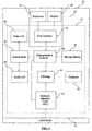
- FIG. 1 is a block diagram of an exemplary system for logging and displaying audio and/or visual data from communication sessions performed over a computer network.
- a computer logging system 10 features a user computer 12 connected to a communication session management unit 13.
- Communication session management unit 13 is in turn connected to an intranet 14 through a network interface card (NIC) 16.
- NIC network interface card
- User computer 12 includes a user interface 18, which is preferably a GUI (graphical user interface), which is displayed on a display unit 20.
- User interface 18 preferably enables the user to enter such information as the definition of the parties whose calls should to be monitored and/or logged, and which also preferably enables the user to enter at least one command for retrieving and displaying a communication session.
- Display unit 20 is preferably a computer monitor.
- the user is able to interact with user computer 12 by entering data and commands through a data entry device 22.
- Data entry device 22 preferably includes at least a keyboard or a pointing device such as a mouse, and more preferably includes both a keyboard and a pointing device.
- user computer 12 is a PC (personal computer).
- user computer 12 is a "thin client" such a net computer which is a computer able to communicate on an IP-based network.
- One example of such a net computer is the JavaStationTM (Sun Microsystems).
- the advantage of such net computers is that they allow the user to interact with complex, sophisticated software programs, yet generally do not have all of the powerful computing capabilities of currently available PC computers.
- Intranet 14 could be a LAN or a WAN, for example.
- the connection between communication session management unit 13 and intranet 14 occurs through NIC 16.
- NIC 16 is preferably any standard, off-the-shelf commercial product which enables communication session management unit 13 to be connected to any suitable computer network (for example, Etherlink II ISA/PCMCIA Adapter or Etherlink III PCI Bus-Master Adapter (3c590) of 3-ComTM, or NE2000 Adapter of NovellTM or any other such suitable product).
- suitable computer networks include, but are not limited to, any standard LAN such as Ethernet (IEEE Standard 802.3), Fast Ethernet (IEEE Standard 802.10), Token Ring (IEEE Standard 802.5) and FDDI.
- filtering module 24 screens the data packets in order to determine which data packets fulfill the following criteria.
- the data packets should be IP packets with headers according to the H.225 and H.245 standards, indicating voice and/or video traffic.
- H.225 and H.245 standards indicating voice and/or video traffic.
- these standards define media stream packet construction and synchronization for visual telephone systems and the control protocol for multimedia communications.
- Filtering module 24 then preferably passes substantially only those data packets which meet these criteria to a management module 28.
- filtering module 24 preferably also transfers messages from other communication session management units.
- Management module 28 receives the data packets passed through by filtering module 24, and analyzes the received data packets.
- a database 26 stores such information as the IP addresses of parties whose communication sessions should be logged, as well as the conversion table associating each party with at least one IP address, for example.
- the stored list of IP addresses representing those parties whose calls should be logged is preferably user-defined.
- the term "party” refers to a person or persons communicating through a computer network-based telephone system. The latter preferred requirement significantly reduces the amount of data stored by including only data which is of interest to the user.
- Management module 28 analyzes and manages data in accordance with the applicable H.225 and H.245 specifications, including the H.245 control function, RAS signaling function and call signaling function, substantially as described above in the "Description of the Background Art" section.
- Management module 28 analyzes the packets in order to determine the specific communication session to which the data packets belong, the type of data compression being used (if any), and whether the data packets were sent from an IP address which should be monitored. Management module 28 must perform this analysis since filtering module 24 simply passes all data packets which fulfill the criteria described briefly above (see Figures 3A-3D for more detail). Since these packets are passed without regard to any of the information stored in database 26, management module 28 must compare the rules of database 26 to the information present in the packet header of each packet in order to determine whether the received packet should be stored.
- a storage medium 30 which is preferably a high capacity digital data storage device such as a hard disk magnetic storage device, an optical disk, a CD-ROM, a ZIP or DVD drive, or a DAT cassette, or a combination of such devices according to the operational needs of specific applications, or any other suitable storage media.
- a storage medium 30 is preferably a high capacity digital data storage device such as a hard disk magnetic storage device, an optical disk, a CD-ROM, a ZIP or DVD drive, or a DAT cassette, or a combination of such devices according to the operational needs of specific applications, or any other suitable storage media.
- the specific communication session or "telephone call" with which each data packet is associated, is also stored in order for that session to be reconstructed and displayed at a later time.
- management module 28 can then retrieve one or more data packets from storage medium 30 which are associated with one or more communication sessions.
- the retrieved packet or packets are then transferred to a data restore module 32.
- Data restore module 32 is preferably capable of manipulating these retrieved packets to restore a particular communication session by using the RTP (Real Time Protocol).
- RTP Real Time Protocol
- the data packets are sent with a time stamp in the header rather than just a sequence number.
- Such a time stamp is necessary for audio and video stream data, in order for the data packets to be reassembled such that the overall timing of the stream of data is maintained. Without such a time stamp, the proper timing would not be maintained, and the audio or video streams could not be accurately reconstructed.
- a CODEC is a non-linear method for the conversion of analog and digital data.
- an audio CODEC enables the digitized audio data in relevant data packets to be converted to analog audio data for display to the user as audible sounds, for example.
- Suitable CODEC's are described in greater detail below with regard to Figure 5.
- system 10 preferably features an audio unit 34 and a video unit 36, collectively referred to as a "communication session display unit". More preferably, both audio unit 34 and video unit 36 are capable of both receiving audio or video input, respectively, and of displaying audio or video output At the very least, audio unit 34 and video unit 36 should be able to display audio or video output, respectively.
- audio unit 34 could optionally include an microphone for input and a speaker or an earphone for output.
- Video unit 36 could optionally include a video monitor or display screen for output and a video camera for input, for example.
- FIG 2 is a schematic block diagram of system 10 of Figure 1, showing the overall system of software modules of system 10 in more detail. Reference is also made, where appropriate, to flow charts showing the operation of these software modules in more detail ( Figures 3A-3D and Figure 5), as well as to descriptions of the headers of the different types of data packets ( Figures 4A-4D).
- system 10 again includes a connection to intranet 14 through NIC 16. As the packets are transmitted through intranet 14, NIC 16 intercepts these data packets and passes them to filtering module 24.
- Filtering module 24 has two components.
- a first filtering component 38 examines the header of the data packet, which should be an IP type packet with the correct header, as shown in Figure 4A below.
- first filtering component 38 passes the data packet to a second filtering component 40.
- Second filtering component 40 determines the type of IP data packet, which could be constructed according to the H.225, H.245, RTP or RTCP standards.
- first filtering component 38 and second filtering component 40 operate as follows.
- step one a packet is received by filtering module 24.
- the packet is given to first filtering component 38, which then determines whether the packet is an IP type packet in step two.
- Such a determination is performed to the structure of the header of the data packet, an example of which is shown in Figure 4A.
- a header 42 is shown as a plurality of boxes, each of which represents a portion or "field" of the header. The number of bytes occupied by each portion is also shown, it being understood that each layer consists of 32 bits.
- the first portion of the header, a "VERS" portion 44 is the protocol version number. Next, an "H.
- LEN portion 46 indicates the number of 32-bit quantities in the header
- a "SERVICE TYPE” portion 48 indicates whether the sender prefers the datagram to travel over a route with minimal delay or a route with maximal throughput.
- a "TOTAL LENGTH” portion 50 indicates the total number of octets in both the header and the data.
- an "IDENTIFICATION" portion 52 identifies the packet itself.
- a "FLAGS” portion 54 indicates whether the datagram is a fragment or a complete datagram.
- a "FRAGMENT OFFSET” portion 56 specifies the location of this fragment in the original datagram, if the datagram is fragmented.
- a "TIME TO LIVE'' portion 58 contains a positive integer between 1 and 255, which is progressively decremented at each route traveled. When the value becomes 0, the packet will no longer be passed and is returned to the sender.
- a "TYPE” portion 60 indicates the type of data being passed.
- a "HEADER CHECKSUM” portion 62 enables the integrity of the packet to be checked by comparing the actual checksum to the value recorded in portion 62.
- the next layer of header 42 contains the source IP address 64, after which the following layer contains the destination IP address 66.
- An optional IP OPTIONS portion 68 is present, after which there is padding (if necessary) and a data portion 70 of the packet containing the data begins.
- first filtering component 38 determines whether this header has the necessary data fields in the correct order, such that the header of the data packet has a structure according to header 42.
- First filtering component 38 only allows those packets with the correct header structure to pass, as shown in step 3A. Otherwise, the packets are dumped as shown in step 3B.
- Second filtering component 40 then performs the remainder of the filtering steps.
- second filtering component 40 examines the IP packets to determine their type from the data portion of the packet as shown in Figure 4A.
- the packets could be in one of four categories: H.225, H.245, RTP and RTCP.
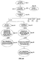
- the steps of the method for H.225 packets are shown in Figure 3A, while the procedures for the remaining packet types are shown in Figures 3B-3D, respectively.
- both the packet itself and the information regarding the type of packet are both passed to management module 28, as shown in Figure 2.
- the packet is then passed to the relevant component within management module 28, also as shown in Figure 2, for the recording process to be performed.
- the recorded packets are stored in storage module 30, as described in greater detail below with regard to Figures 3C and 3D.
- the packet is passed to an H.225 call control module 78 within management module 28, as shown in Figure 2.
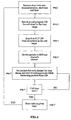
- the steps of the management method are as follows, with reference to Figure 3A.
- the H.225 packet is examined to see if it is a setup packet, which is determined according to the structure of the data in the packet. This structure is specified in the H.225.0 recommendation, and includes at least the following types of information:
- step 5A database 26 of Figure 1 is then examined to determine whether either of the corresponding terminals is defined as a recording terminal; that is, whether communication sessions initiated by the IP address of this terminal should be monitored. If true, then in step 6A, the terminal status is set as a start session request from the terminal corresponding to the source port.
- the packet is examined to see if it is a connect packet in step 4B, which is determined according to the structure of the data in the packet.
- This structure is specified in the H.225.0 recommendation, and includes at least the following types of information:
- step 5B the flag indicating the terminal status is examined to determine if the terminal status is set as a start session request.
- the details of the call signal are saved in a call progress database 78 of storage medium 30 (see Figure 2). These details preferably include the source and destination IP addresses, the source and destination ports; the time at which the communication session was initiated, and any other relevant information.
- step 7B the status of the terminal is set to "wait for the logic channel".
- H.245 call control module 82 within management module 28, as shown in Figure 2.
- H.245 packets are necessary for H.245 signaling.
- H.245 signaling is established between two endpoints: an endpoint and a multi-point controller, or an endpoint and a Gatekeeper (see Figures 6 and 7 below for examples and a description of such endpoints).
- Each endpoint is capable of calling and of being called as part of a communication session.
- the system of the present invention only monitors, rather than initiating, such communication sessions.
- the system of the present invention uses the H.245 signaling to determine when the communication session has started in order to effectively record the necessary data packets for the storage and later reconstruction of the session.
- step 1A of Figure 3B the H.245 packet is examined to determine if it is an open logical channel request packet. If it is, then in step 2A, the terminal status is examined to determine if the status is "wait for the logical channel”. If so, then in step 3A the terminal status is set to "wait for acknowledgment".
- the H.245 packet is examined to determine if it is an open logical channel acknowledgment packet, as shown in step 1B. If it is, then in step 2B, the terminal status is examined to determine if the status is "wait for acknowledgment”. If so, then in step 3B the terminal status is set to "wait for terminal capability". In step 4B, the transport address of the "called" or destination terminal is saved. This transport address is taken from the destination port field 76 of header 72 (see Figure 4B). It should be noted that H.225 and H.245 packets have identical header structures.
- the H.245 packet is examined to determine if it is a terminal capability set packet, as shown in step 1C. If it is, then in step 2C, the terminal capability is saved in call progress database 80 (see Figure 2). In step 3C, the terminal status is set to "in call process", such that the communication session has been determined to be opened and such that management module 28 can now receive RTP data packets.
- the packet is passed to a RAS (registration, admissions and status) control module 84 within management module 28, as shown in Figure 2.
- RAS registration, admissions and status
- the steps of the management method for RTP packets are as follows, with reference to Figure 3C.
- step 1 of Figure 3C the terminal status is examined to see if it is "in call process”. If so then in step 2, the RTP packets are saved in a RTP database 86 within storage medium 30 (see Figure 2).
- Figure 4C shows the structure of the RTP packet header, which can be used to identify the communication session from which the packet was taken.
- the packet is passed to a RTCP control module 88 within management module 28, as shown in Figure 2.
- the steps of the management method for RTCP packets are as follows, with reference to Figure 3D.
- the terminal status is examined to see if it is "in call process”. If so then in step 2, the RTCP packets are saved in call progress database 80 within storage medium 30 (see Figure 2).
- Figure 4D shows the structure of the RTCP packet header, which can be used to identify the communication session from which the packet was taken.
- Figures 3A-3D illustrate the method of the present invention with regard to the filtering and storage of data packets which constitute the recorded communication session, as recorded by the system of the present invention as shown in Figures 1 and 2.
- the system of the present invention is also able to retrieve and to replay these communication sessions to the user.
- the stored communication session composed of stored data packets, can be retrieved and displayed by data restore unit 32 of Figure 2, in conjunction with audio unit 34 and video unit 36.
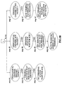
- the method of retrieving and replaying sessions of interest is shown in Figure 5, while certain other relevant portions of the system of the present invention are shown in Figure 2.
- step 1 of Figure 5 the user inputs the information concerning the communication session which is to be retrieved and replayed.
- This information preferably includes the terminal number, or other designation information concerning at least one of the parties of the communication session of interest; the time at which the session started; and the time at which the session ended.
- other information could be included in place of this information, as long as sufficient information is provided for the communication session of interest to be identified.
- call progress database 80 (see Figure 2) is searched by data restore unit 32 in order to find the details of the communication session(s) in the specified time range. These details are then compared to the information entered by the user to locate at least one communication session of interest in the call range.
- step 3 RTP database 86 of storage medium 30 (see Figure 2) is searched, again by data restore unit 32, to find substantially all data packets from the at least one communication session in the specified call range.
- step 4 if the audio portion communication session was recorded in stereo, then the data packets are divided into different audio channels.
- step 5 the data packets are restored by data restore unit 32 by an RTP (Real Time Protocol) software module 91 within data restore unit 32.
- RTP software module 91 orders the data packets within each channel according to the time stamp of each packet.
- an RTP packet header 92 features several important fields: a timestamp field 94, a synchronization source (SSRC) identifiers field 96 and a contributing source (CSRC) identifiers field 98.
- SSRC field 96 is used to determine the source of the RTP packets (the sender), which has a unique identifying address (the SSRC identifier).
- the CSRC identifier in CSRC field 98 is used in a conference with multiple parties, and indicates the SSRC identifier of all parties.
- Timestamp field 94 is used by RTP software module 91 to determine the relative time at which the data in each packet should be displayed.
- the audio stream data of the audio speech of one person is synchronized to that person's lip movements as shown in the video stream, a process known as "lip synchronization".
- lip synchronization requires more than simply replaying audio and video data at certain relative time points, since the audio and video data packets may not arrive at the same time, and may therefore have slightly different timestamps.
- control of the display of the audio data is then performed by an audio component 102 of data restore unit 32 according to one or more audio CODEC's (see Figure 2).
- the control of the display of the video data is then performed by a video component 100 of data restore unit 32 according to one or more video CODEC's (see Figure 2).
- Suitable CODEC's include, but are not limited to, an audio codec using CCITT Recommendation G.711 (1988), Pulse Code Modulation ( PCM ) of voice frequencies; an audio codec using CCITT Recommendation G.722 (1988), 7 kHz audio-coding within 64 kbit / s; an audio codec using ITU-T Recommendation G.723.1 ( 1996 ) , Speech coders: Dual rate speech coder for multimedia communications transmitting at 5.3 and 6 3 Kbps; an audio codec using CCITT Recommendation G. 728 (1992), Coding of speech at 16 Kbps using low-delay code excited linear prediction; an audio codec using ITU-T Recommendation G.
- Step 5 of Figure 5 is then preferably repeated, such that substantially the entirety of the communication session is displayed.
- each data packet of the communication session is examined to see if the call time is over. If the individual session has not completed, preferably step 5 is repeated. Alternatively and preferably, if the call time is over, then call progress database 80 is searched to see if other communication sessions were recorded within the given time period, as shown in step 7. If there is at least one other such communication session, then preferably the method of Figure 5 is repeated, starting from step 2.
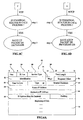
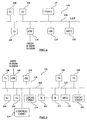
- a typical basic configuration system 104 includes a single communication session management unit 13, substantially as shown in Figures 1 and 2, according to the present invention.
- Communication session management unit 13 manages communication in a stand-alone intranet such as a LAN 106.
- LAN 106 is connected both to communication session management unit 13 and to a plurality of terminals 108, designated as "T1", "T2" and so forth, which follow the H.323 protocol.
- Each terminal 108 is an endpoint on LAN 106 which provides for real-time, two-way communications with another terminal 108, a gateway 110, or a multipoint control unit (MCU) 112.
- MCU multipoint control unit
- This communication consists of control, indications, audio streams, video streams, and/or data.
- Terminal 108 is optionally only capable of providing such communication for audio only, audio and data, audio and video, or audio, data and video.
- the H.323 entity could be a terminal which is capable of providing audio and/or video communication as a "LAN telephone", but could also be a stand-alone audio or video telephone.
- Gateway 110 is constructed according to H.323 and is an endpoint on LAN 106 which provides for real-time, two-way communications between terminals 108 on LAN 106 and other suitable terminals on a WAN (not shown), or to another such Gateway (not shown).
- Other suitable terminals include those complying with Recommendations H.310 (H.320 on B-ISDN), H.320 (ISDN), H.321 (ATM), H.322 (GQOS-LAN), H.324 (GSTN), H.324M (Mobile), and V.70 (DSVD).
- MCU 112 is an endpoint on LAN 106 which enables three or more terminals 108 and gateways 110 to participate in a multipoint conference.
- system 104 also features a gatekeeper (GK) 114, which is an H.323 entity on LAN 106 which provides address translation and controls access to LAN 106 for terminals 108, gateways 110 and MCUs 112.
- GK gatekeeper
- Gatekeeper 114 may also provide other services to terminals 108, gateways 110 and MCUs 112 such as bandwidth management and locating gateways 110.
- gatekeeper 114 enables the IP address of terminals 108 on LAN 106 to be determined, such that the correct IP address can be determined "on the fly”.
- LAN 106 may support non audio visual devices for regular T.120 data applications such as electronic whiteboards, still image transfer, file exchange, database access, etc.
- a single, stand-alone communication session management unit 13 is used for monitoring, logging and retrieval of all audio and/or visual calls either between any two or more terminals 108 attached to LAN 106 or any call to which one or more of these terminals 108 is a party.
- RAS control module 84 also performs RAS signaling between the management control module and NIC 16 where necessary for the configuration of the system.
- RAS signaling uses H.225.0 messages to perform registration, admissions, bandwidth changes, status, and disengage procedures between endpoints and gatekeepers. These messages are passed on a RAS Signaling Channel, which is independent from the Call Signaling Channel and the H.245 Control Channel. H.245 open logical channel procedures are not used to establish the RAS Signaling Channel.
- the RAS Signaling Channel is opened between the endpoint and the Gatekeeper.
- the RAS Signaling Channel is opened prior to the establishment of any other channels between H.323 endpoints.
- FIG. 7 shows a second embodiment of the system of the present invention as a zone configuration system 116.
- a zone 118 is the collection of all terminals (Tx) 108, gateways (GW) 110 , and multipoint control units (MCUs) 112 managed by a single gatekeeper (GK) 114 .
- Zone 118 includes at least one terminal 108, but does not necessarily include one or more gateways 110 or MCUs 112.
- Zone 118 has only one gatekeeper 114 as shown.
- zone 118 is preferably independent of LAN topology and preferably includes multiple LAN segments 120 which are connected using routers (R) 122 as shown or other similar devices.
- Each monitored LAN segment 120 has a local communication management unit 124 according to the present invention, of which two are shown.
- a central management unit 126 controls all local communication management units 124.
- central management unit 126 can be used for the real-time monitoring and off-line restoration of audio and/or video communication sessions from a single point.
- Central management unit 126 is optionally and preferably either a dedicated unit similar in structure to local communication management units 124 but without the storage capability, or central management unit 126 is alternatively and preferably integrated with local communication management units 124 to provide the functionality of both local communication management unit 124 and central management unit 126 in a single station.
- Local communication management units 124 are preferably either communication session management units 13 substantially as described in Figures 1 and 2, or alternatively and preferably are simpler units which lack the capability to retrieve and display a communication session locally.
- multi-user operation based on Client/Server architecture is preferably supported for basic system 104 and zone system 116.
- An unlimited number of "Client" stations may be connected anywhere on the LAN, providing users with management and monitoring/retrieval capabilities determined by the authorization level of each specific user.
- Yet another preferred embodiment of the present invention addresses the challenges of an Intemet Protocol (IP) distributed switching environment.
- IP Intemet Protocol
- System 104 of Figure 6 is intended for use in a standard H.323 environment.
- Terminals 108 conduct telephone conversations among themselves, or alternatively with POTS telephones via gateway 110.
- terminals 108 communicate with gatekeeper 114 in order to find the destination terminal or gateway on LAN using the RAS protocol to perform call setup under the H.225 protocol and to negotiate the RTP stream characteristics under the H.245 protocol. Note that these protocols all belong to the H.323 protocol suite.
- the communication with gatekeeper 114, under the RAS, H.225 and H.245 protocols, is the signaling part of the call and is used to establish the RTP or RTCP streams of the call which are used to carry the actual voice or video data.
- MCU 112 provides the ability to perform conferencing among three or more parties. All of the above communications are performed over LAN 106.
- Communication session management unit 13 is connected on LAN 106 in such a way that communication session management unit 13 is able to sniff all the packets of a conversation, both signaling packets and RTP or RTCP packets.
- Prior art connection methods include:
- Communication session management unit 13 sniffs the RTP and RTCP packets of the conversation and extracts the voice or video data from these packets. In order to associate these data with a telephone extension number, or with the name of the person at the extension, the H.323 signaling must be analyzed. This solution does not work in Voice Over IP systems in which the signaling protocols are not within the H.323 protocol suite. Such signaling protocols include SIP, MGCP and Cisco's proprietary Skinny protocol.
- a third embodiment 150 of the system of the present invention that does not depend on the signaling protocol, is illustrated in Figure 8.
- system 150 the voice or video data are recorded, as in system 104 of Figure 6, by having communication session management unit 13 sniff the RTP and RTCP packets.
- the innovation of system 150 is the addition of a link 160 between communication session management unit 13 and gatekeeper 114.
- link 160 connects management module 28 of communication session management unit 13 to gatekeeper 114.
- Link 160 provides CTI (computer telephone integration) data or CDR (call data records) data to communication session management unit 13. These data replace the data which are retrieved by analyzing the H.323 protocols in system 104 of Figure 6.
- caller's IP address and other identifying information, such as extension number, caller's name, or any other information that arrives via link 160.
- the caller's IP address may be inferred from the other identifying information.
- Link 160 is a logical link that may be implemented in several ways, including:
- System 150 of Figure 8 may be reduced to practice using the following commercially available components:
Abstract
Description
Claims (10)
- A system (10) for managing a communication session over a computer network (14) that includes a gate keeper (114), the system (10) comprising:characterized in that said filtering unit (24) accepts said data packets substantially only if said data packets contain data selected from the group consisting of audio data and video data, and in that the system further comprises:(a) a network connector (16) for connecting to the computer network (14) and for receiving data packets from the computer network (14);(b) a filtering unit (24) for filtering said data packets, such that said data packets form at least a portion of the communication session and such that said data packets are selected data packets;(c) a management unit (28) for receiving said selected data packets and for storing said selected data packets, such that said selected data packets are stored data packets; and(d) a storage medium (30) for receiving and for storing said stored data packets from said management unit (28), such that said at least a portion of the communication session is stored;(e) a link (160), between the gatekeeper (114) and said management unit (28), for transferring information related to said data packets from the gatekeeper (114) to said management unit (28).
- The system of claim 1, further comprising:(f) a data restore unit (32) for retrieving and displaying said at least a portion of the communication session, said data restore unit (32) requesting said data packets from said storage medium (30) through said management unit (28), and said data restore unit (32) reconstructing said data packets for displaying said at least a portion of the communication session.
- The system (10) of claim 2, wherein said data restore unit (32) further comprises a communication session display unit (34, 36) for displaying said at least a portion of the communication session.
- The system (10) of claim 3, wherein said communication session display unit (34, 36) is selected from the group consisting of a video unit (36) and an audio unit (34).
- The system (10) of claim 2, further comprising:wherein said filtering unit (24) accepts said data packets according to said filtering information, such that said filtering unit (24) substantially only accepts said data packets if said data packets fulfill said filtering information.(g) a database (26) connected to said filtering unit (24) for storing filtering information, said filtering information including at least one LP address of a party whose communication sessions are monitored;
- The system (10) of claim 5, further comprising:(h) a user computer (12) for receiving at least one command of a user and for displaying information to said user, such that said user determines said filtering information according to said at least one command of said user.
- The system (10) of claim 6, wherein the computer network (14) is selected from the group consisting of a LAN (local area network) (106) and a WAN (wide area network).
- The system (10) of claim 7, wherein the computer network is a LAN (local area network) (106).
- The system (10) of claim 8, wherein said LAN (106) is divided into at least two segments (120), the system (10) further comprising:(i) a local management unit (124) for each segment (120), said local management unit (124) including said filtering unit (24) and said management unit (28); and(j) a central management unit (126) for controlling said local management units (124), said central management unit (126) controlling storage in said storage medium (30).
- The system (10) of claim 1, wherein said network connector (16) is a network interface card (16).
Priority Applications (3)
| Application Number | Priority Date | Filing Date | Title |
|---|---|---|---|
| EP05112197A EP1635535A3 (en) | 2000-09-19 | 2001-09-16 | Communication management system for recording communications sessions |
| EP05112192A EP1635534B1 (en) | 2000-09-19 | 2001-09-16 | Communication management system for recording at least a portion of a communication session |
| DE60116341.9T DE60116341T3 (en) | 2000-09-19 | 2001-09-16 | COMMUNICATION MANAGEMENT SYSTEM FOR COMPUTER-BASED TELEPHONES |
Applications Claiming Priority (3)
| Application Number | Priority Date | Filing Date | Title |
|---|---|---|---|
| US66475500A | 2000-09-19 | 2000-09-19 | |
| US664755 | 2000-09-19 | ||
| PCT/IL2001/000874 WO2002025889A2 (en) | 2000-09-19 | 2001-09-16 | Communication management system for computer network based telephones |
Related Child Applications (4)
| Application Number | Title | Priority Date | Filing Date |
|---|---|---|---|
| EP05112192A Division EP1635534B1 (en) | 2000-09-19 | 2001-09-16 | Communication management system for recording at least a portion of a communication session |
| EP05112192A Division-Into EP1635534B1 (en) | 2000-09-19 | 2001-09-16 | Communication management system for recording at least a portion of a communication session |
| EP05112197A Division-Into EP1635535A3 (en) | 2000-09-19 | 2001-09-16 | Communication management system for recording communications sessions |
| EP05112197A Division EP1635535A3 (en) | 2000-09-19 | 2001-09-16 | Communication management system for recording communications sessions |
Publications (3)
| Publication Number | Publication Date |
|---|---|
| EP1319299A2 EP1319299A2 (en) | 2003-06-18 |
| EP1319299B1 true EP1319299B1 (en) | 2005-12-28 |
| EP1319299B2 EP1319299B2 (en) | 2016-11-09 |
Family
ID=24667311
Family Applications (3)
| Application Number | Title | Priority Date | Filing Date |
|---|---|---|---|
| EP05112192A Expired - Lifetime EP1635534B1 (en) | 2000-09-19 | 2001-09-16 | Communication management system for recording at least a portion of a communication session |
| EP01972435.0A Expired - Lifetime EP1319299B2 (en) | 2000-09-19 | 2001-09-16 | Communication management system for computer network based telephones |
| EP05112197A Withdrawn EP1635535A3 (en) | 2000-09-19 | 2001-09-16 | Communication management system for recording communications sessions |
Family Applications Before (1)
| Application Number | Title | Priority Date | Filing Date |
|---|---|---|---|
| EP05112192A Expired - Lifetime EP1635534B1 (en) | 2000-09-19 | 2001-09-16 | Communication management system for recording at least a portion of a communication session |
Family Applications After (1)
| Application Number | Title | Priority Date | Filing Date |
|---|---|---|---|
| EP05112197A Withdrawn EP1635535A3 (en) | 2000-09-19 | 2001-09-16 | Communication management system for recording communications sessions |
Country Status (8)
| Country | Link |
|---|---|
| EP (3) | EP1635534B1 (en) |
| JP (1) | JP2004509563A (en) |
| AT (2) | ATE394865T1 (en) |
| AU (1) | AU781291B2 (en) |
| DE (2) | DE60133949D1 (en) |
| HK (2) | HK1058267A1 (en) |
| WO (1) | WO2002025889A2 (en) |
| ZA (1) | ZA200202928B (en) |
Cited By (3)
| Publication number | Priority date | Publication date | Assignee | Title |
|---|---|---|---|---|
| USRE40634E1 (en) | 1996-09-26 | 2009-02-10 | Verint Americas | Voice interaction analysis module |
| US8098851B2 (en) | 2009-05-29 | 2012-01-17 | Mathias Stieler Von Heydekampf | User interface for network audio mixers |
| US8385566B2 (en) | 2009-05-29 | 2013-02-26 | Mathias Stieler Von Heydekampf | Decentralized audio mixing and recording |
Families Citing this family (17)
| Publication number | Priority date | Publication date | Assignee | Title |
|---|---|---|---|---|
| US6871229B2 (en) | 1998-08-26 | 2005-03-22 | Sts Software Systems Ltd. | Method for storing on a computer network a portion of a communication session between a packet source and a packet destination |
| WO2005086046A1 (en) * | 2004-03-10 | 2005-09-15 | Nice Systems Ltd. | Apparatus and method for generating a content-based follow up |
| US8094790B2 (en) | 2005-05-18 | 2012-01-10 | Mattersight Corporation | Method and software for training a customer service representative by analysis of a telephonic interaction between a customer and a contact center |
| US7995717B2 (en) | 2005-05-18 | 2011-08-09 | Mattersight Corporation | Method and system for analyzing separated voice data of a telephonic communication between a customer and a contact center by applying a psychological behavioral model thereto |
| US8094803B2 (en) | 2005-05-18 | 2012-01-10 | Mattersight Corporation | Method and system for analyzing separated voice data of a telephonic communication between a customer and a contact center by applying a psychological behavioral model thereto |
| CN101496356B (en) * | 2006-06-29 | 2013-10-16 | 瓦林特美国股份有限公司 | Systems and methods for providing recording as a network service |
| US7903568B2 (en) | 2006-06-29 | 2011-03-08 | Verint Americas Inc. | Systems and methods for providing recording as a network service |
| US8023639B2 (en) | 2007-03-30 | 2011-09-20 | Mattersight Corporation | Method and system determining the complexity of a telephonic communication received by a contact center |
| US8718262B2 (en) | 2007-03-30 | 2014-05-06 | Mattersight Corporation | Method and system for automatically routing a telephonic communication base on analytic attributes associated with prior telephonic communication |
| US7869586B2 (en) | 2007-03-30 | 2011-01-11 | Eloyalty Corporation | Method and system for aggregating and analyzing data relating to a plurality of interactions between a customer and a contact center and generating business process analytics |
| US10419611B2 (en) | 2007-09-28 | 2019-09-17 | Mattersight Corporation | System and methods for determining trends in electronic communications |
| US9258337B2 (en) | 2008-03-18 | 2016-02-09 | Avaya Inc. | Inclusion of web content in a virtual environment |
| US8630234B2 (en) | 2008-07-28 | 2014-01-14 | Digifonica (International) Limited | Mobile gateway |
| EP2164232B1 (en) * | 2008-09-10 | 2016-01-13 | Axis AB | Network connector device |
| US8443075B2 (en) * | 2009-10-29 | 2013-05-14 | Fluke Corporation | Transaction storage determination via pattern matching |
| US9191510B2 (en) | 2013-03-14 | 2015-11-17 | Mattersight Corporation | Methods and system for analyzing multichannel electronic communication data |
| CN109005466B (en) * | 2018-09-03 | 2020-07-10 | 视联动力信息技术股份有限公司 | Subtitle display method and device |
Family Cites Families (9)
| Publication number | Priority date | Publication date | Assignee | Title |
|---|---|---|---|---|
| US5136655A (en) * | 1990-03-26 | 1992-08-04 | Hewlett-Pacard Company | Method and apparatus for indexing and retrieving audio-video data |
| EP0739558B1 (en) * | 1993-06-09 | 2003-04-16 | BTG International Inc. | Method and apparatus for multiple media digital communication system |
| US5664226A (en) * | 1994-09-08 | 1997-09-02 | International Business Machines Corporation | System for merging plurality of atomic data elements into single synchronized file by assigning ouput rate to each channel in response to presentation time duration |
| WO1997041674A2 (en) * | 1996-04-30 | 1997-11-06 | 3Com Corporation | Packet filtering based on socket or application identification |
| US6170011B1 (en) * | 1998-09-11 | 2001-01-02 | Genesys Telecommunications Laboratories, Inc. | Method and apparatus for determining and initiating interaction directionality within a multimedia communication center |
| US7043749B1 (en) * | 1998-02-27 | 2006-05-09 | Tandberg Telecom As | Audio-video packet synchronization at network gateway |
| US6760748B1 (en) * | 1999-01-20 | 2004-07-06 | Accenture Llp | Instructional system grouping student terminals |
| WO2000052916A1 (en) * | 1999-03-05 | 2000-09-08 | Gric Communications, Inc. | Method and system for internet telephony using gateway |
| US6535920B1 (en) * | 1999-04-06 | 2003-03-18 | Microsoft Corporation | Analyzing, indexing and seeking of streaming information |
-
2001
- 2001-09-16 JP JP2002528977A patent/JP2004509563A/en active Pending
- 2001-09-16 EP EP05112192A patent/EP1635534B1/en not_active Expired - Lifetime
- 2001-09-16 AT AT05112192T patent/ATE394865T1/en not_active IP Right Cessation
- 2001-09-16 DE DE60133949T patent/DE60133949D1/en not_active Expired - Lifetime
- 2001-09-16 DE DE60116341.9T patent/DE60116341T3/en not_active Expired - Lifetime
- 2001-09-16 AT AT01972435T patent/ATE314780T1/en not_active IP Right Cessation
- 2001-09-16 EP EP01972435.0A patent/EP1319299B2/en not_active Expired - Lifetime
- 2001-09-16 AU AU92200/01A patent/AU781291B2/en not_active Expired
- 2001-09-16 WO PCT/IL2001/000874 patent/WO2002025889A2/en active IP Right Grant
- 2001-09-16 EP EP05112197A patent/EP1635535A3/en not_active Withdrawn
-
2002
- 2002-04-15 ZA ZA200202928A patent/ZA200202928B/en unknown
-
2003
- 2003-12-18 HK HK03109239A patent/HK1058267A1/en not_active IP Right Cessation
-
2006
- 2006-07-18 HK HK06108027A patent/HK1091620A1/en not_active IP Right Cessation
Cited By (8)
| Publication number | Priority date | Publication date | Assignee | Title |
|---|---|---|---|---|
| USRE40634E1 (en) | 1996-09-26 | 2009-02-10 | Verint Americas | Voice interaction analysis module |
| USRE41534E1 (en) | 1996-09-26 | 2010-08-17 | Verint Americas Inc. | Utilizing spare processing capacity to analyze a call center interaction |
| USRE43183E1 (en) | 1996-09-26 | 2012-02-14 | Cerint Americas, Inc. | Signal monitoring apparatus analyzing voice communication content |
| USRE43255E1 (en) | 1996-09-26 | 2012-03-20 | Verint Americas, Inc. | Machine learning based upon feedback from contact center analysis |
| USRE43324E1 (en) | 1996-09-26 | 2012-04-24 | Verint Americas, Inc. | VOIP voice interaction monitor |
| USRE43386E1 (en) | 1996-09-26 | 2012-05-15 | Verint Americas, Inc. | Communication management system for network-based telephones |
| US8098851B2 (en) | 2009-05-29 | 2012-01-17 | Mathias Stieler Von Heydekampf | User interface for network audio mixers |
| US8385566B2 (en) | 2009-05-29 | 2013-02-26 | Mathias Stieler Von Heydekampf | Decentralized audio mixing and recording |
Also Published As
| Publication number | Publication date |
|---|---|
| EP1635534A2 (en) | 2006-03-15 |
| EP1319299B2 (en) | 2016-11-09 |
| WO2002025889A3 (en) | 2002-08-15 |
| EP1635535A3 (en) | 2006-06-07 |
| DE60133949D1 (en) | 2008-06-19 |
| AU781291B2 (en) | 2005-05-12 |
| ATE314780T1 (en) | 2006-01-15 |
| HK1091620A1 (en) | 2007-01-19 |
| DE60116341T3 (en) | 2017-04-06 |
| EP1319299A2 (en) | 2003-06-18 |
| WO2002025889A2 (en) | 2002-03-28 |
| EP1635535A2 (en) | 2006-03-15 |
| EP1635534B1 (en) | 2008-05-07 |
| AU9220001A (en) | 2002-04-02 |
| DE60116341D1 (en) | 2006-02-02 |
| EP1635534A3 (en) | 2006-06-07 |
| DE60116341T2 (en) | 2006-08-03 |
| ZA200202928B (en) | 2002-12-18 |
| ATE394865T1 (en) | 2008-05-15 |
| JP2004509563A (en) | 2004-03-25 |
| HK1058267A1 (en) | 2004-05-07 |
Similar Documents
| Publication | Publication Date | Title |
|---|---|---|
| US7581001B2 (en) | Communication management system for computer network-based telephones | |
| EP1108239B1 (en) | Communication management system for computer network-based telephones | |
| EP1319299B1 (en) | Communication management system for computer network based telephones | |
| US7286652B1 (en) | Four channel audio recording in a packet based network | |
| US7548539B2 (en) | Method and apparatus for Voice-over-IP call recording | |
| EP2067348B1 (en) | Process for scalable conversation recording | |
| KR100598351B1 (en) | The conference aparatus applied between another networks | |
| Schulzrinne et al. | IETF Protocols for IP Telephony | |
| Eldridge | Voice and Data Network of Convergence and the Application of Voice over IP |
Legal Events
| Date | Code | Title | Description |
|---|---|---|---|
| PUAI | Public reference made under article 153(3) epc to a published international application that has entered the european phase |
Free format text: ORIGINAL CODE: 0009012 |
|
| 17P | Request for examination filed |
Effective date: 20030410 |
|
| AK | Designated contracting states |
Designated state(s): AT BE CH CY DE DK ES FI FR GB GR IE IT LI LU MC NL PT SE TR |
|
| AX | Request for extension of the european patent |
Extension state: AL LT LV MK RO SI |
|
| 17Q | First examination report despatched |
Effective date: 20040624 |
|
| GRAP | Despatch of communication of intention to grant a patent |
Free format text: ORIGINAL CODE: EPIDOSNIGR1 |
|
| GRAS | Grant fee paid |
Free format text: ORIGINAL CODE: EPIDOSNIGR3 |
|
| GRAA | (expected) grant |
Free format text: ORIGINAL CODE: 0009210 |
|
| AK | Designated contracting states |
Kind code of ref document: B1 Designated state(s): AT BE CH CY DE DK ES FI FR GB GR IE IT LI LU MC NL PT SE TR |
|
| PG25 | Lapsed in a contracting state [announced via postgrant information from national office to epo] |
Ref country code: NL Free format text: LAPSE BECAUSE OF FAILURE TO SUBMIT A TRANSLATION OF THE DESCRIPTION OR TO PAY THE FEE WITHIN THE PRESCRIBED TIME-LIMIT Effective date: 20051228 Ref country code: LI Free format text: LAPSE BECAUSE OF FAILURE TO SUBMIT A TRANSLATION OF THE DESCRIPTION OR TO PAY THE FEE WITHIN THE PRESCRIBED TIME-LIMIT Effective date: 20051228 Ref country code: IT Free format text: LAPSE BECAUSE OF FAILURE TO SUBMIT A TRANSLATION OF THE DESCRIPTION OR TO PAY THE FEE WITHIN THE PRESCRIBED TIME-LIMIT;WARNING: LAPSES OF ITALIAN PATENTS WITH EFFECTIVE DATE BEFORE 2007 MAY HAVE OCCURRED AT ANY TIME BEFORE 2007. THE CORRECT EFFECTIVE DATE MAY BE DIFFERENT FROM THE ONE RECORDED. Effective date: 20051228 Ref country code: FI Free format text: LAPSE BECAUSE OF FAILURE TO SUBMIT A TRANSLATION OF THE DESCRIPTION OR TO PAY THE FEE WITHIN THE PRESCRIBED TIME-LIMIT Effective date: 20051228 Ref country code: CH Free format text: LAPSE BECAUSE OF FAILURE TO SUBMIT A TRANSLATION OF THE DESCRIPTION OR TO PAY THE FEE WITHIN THE PRESCRIBED TIME-LIMIT Effective date: 20051228 Ref country code: BE Free format text: LAPSE BECAUSE OF FAILURE TO SUBMIT A TRANSLATION OF THE DESCRIPTION OR TO PAY THE FEE WITHIN THE PRESCRIBED TIME-LIMIT Effective date: 20051228 Ref country code: AT Free format text: LAPSE BECAUSE OF FAILURE TO SUBMIT A TRANSLATION OF THE DESCRIPTION OR TO PAY THE FEE WITHIN THE PRESCRIBED TIME-LIMIT Effective date: 20051228 |
|
| REG | Reference to a national code |
Ref country code: GB Ref legal event code: FG4D |
|
| REG | Reference to a national code |
Ref country code: CH Ref legal event code: EP |
|
| REG | Reference to a national code |
Ref country code: IE Ref legal event code: FG4D |
|
| REF | Corresponds to: |
Ref document number: 60116341 Country of ref document: DE Date of ref document: 20060202 Kind code of ref document: P |
|
| PG25 | Lapsed in a contracting state [announced via postgrant information from national office to epo] |
Ref country code: SE Free format text: LAPSE BECAUSE OF FAILURE TO SUBMIT A TRANSLATION OF THE DESCRIPTION OR TO PAY THE FEE WITHIN THE PRESCRIBED TIME-LIMIT Effective date: 20060328 Ref country code: GR Free format text: LAPSE BECAUSE OF FAILURE TO SUBMIT A TRANSLATION OF THE DESCRIPTION OR TO PAY THE FEE WITHIN THE PRESCRIBED TIME-LIMIT Effective date: 20060328 Ref country code: DK Free format text: LAPSE BECAUSE OF FAILURE TO SUBMIT A TRANSLATION OF THE DESCRIPTION OR TO PAY THE FEE WITHIN THE PRESCRIBED TIME-LIMIT Effective date: 20060328 |
|
| PG25 | Lapsed in a contracting state [announced via postgrant information from national office to epo] |
Ref country code: ES Free format text: LAPSE BECAUSE OF FAILURE TO SUBMIT A TRANSLATION OF THE DESCRIPTION OR TO PAY THE FEE WITHIN THE PRESCRIBED TIME-LIMIT Effective date: 20060408 |
|
| PG25 | Lapsed in a contracting state [announced via postgrant information from national office to epo] |
Ref country code: PT Free format text: LAPSE BECAUSE OF FAILURE TO SUBMIT A TRANSLATION OF THE DESCRIPTION OR TO PAY THE FEE WITHIN THE PRESCRIBED TIME-LIMIT Effective date: 20060529 |
|
| NLV1 | Nl: lapsed or annulled due to failure to fulfill the requirements of art. 29p and 29m of the patents act | ||
| REG | Reference to a national code |
Ref country code: CH Ref legal event code: PL |
|
| ET | Fr: translation filed | ||
| PG25 | Lapsed in a contracting state [announced via postgrant information from national office to epo] |
Ref country code: IE Free format text: LAPSE BECAUSE OF NON-PAYMENT OF DUE FEES Effective date: 20060918 |
|
| PG25 | Lapsed in a contracting state [announced via postgrant information from national office to epo] |
Ref country code: MC Free format text: LAPSE BECAUSE OF NON-PAYMENT OF DUE FEES Effective date: 20060930 |
|
| PLBI | Opposition filed |
Free format text: ORIGINAL CODE: 0009260 |
|
| REG | Reference to a national code |
Ref country code: HK Ref legal event code: GR Ref document number: 1058267 Country of ref document: HK |
|
| PLAX | Notice of opposition and request to file observation + time limit sent |
Free format text: ORIGINAL CODE: EPIDOSNOBS2 |
|
| 26 | Opposition filed |
Opponent name: HARRY GRAF SOFTWARE GMBH Effective date: 20060927 |
|
| PLAF | Information modified related to communication of a notice of opposition and request to file observations + time limit |
Free format text: ORIGINAL CODE: EPIDOSCOBS2 |
|
| PLAF | Information modified related to communication of a notice of opposition and request to file observations + time limit |
Free format text: ORIGINAL CODE: EPIDOSCOBS2 |
|
| REG | Reference to a national code |
Ref country code: IE Ref legal event code: MM4A |
|
| PLBB | Reply of patent proprietor to notice(s) of opposition received |
Free format text: ORIGINAL CODE: EPIDOSNOBS3 |
|
| PLAB | Opposition data, opponent's data or that of the opponent's representative modified |
Free format text: ORIGINAL CODE: 0009299OPPO |
|
| PLAY | Examination report in opposition despatched + time limit |
Free format text: ORIGINAL CODE: EPIDOSNORE2 |
|
| PG25 | Lapsed in a contracting state [announced via postgrant information from national office to epo] |
Ref country code: LU Free format text: LAPSE BECAUSE OF NON-PAYMENT OF DUE FEES Effective date: 20060916 Ref country code: TR Free format text: LAPSE BECAUSE OF FAILURE TO SUBMIT A TRANSLATION OF THE DESCRIPTION OR TO PAY THE FEE WITHIN THE PRESCRIBED TIME-LIMIT Effective date: 20051228 |
|
| PG25 | Lapsed in a contracting state [announced via postgrant information from national office to epo] |
Ref country code: CY Free format text: LAPSE BECAUSE OF FAILURE TO SUBMIT A TRANSLATION OF THE DESCRIPTION OR TO PAY THE FEE WITHIN THE PRESCRIBED TIME-LIMIT Effective date: 20051228 |
|
| PLAH | Information related to despatch of examination report in opposition + time limit modified |
Free format text: ORIGINAL CODE: EPIDOSCORE2 |
|
| PLAH | Information related to despatch of examination report in opposition + time limit modified |
Free format text: ORIGINAL CODE: EPIDOSCORE2 |
|
| PLBC | Reply to examination report in opposition received |
Free format text: ORIGINAL CODE: EPIDOSNORE3 |
|
| RDAF | Communication despatched that patent is revoked |
Free format text: ORIGINAL CODE: EPIDOSNREV1 |
|
| APBM | Appeal reference recorded |
Free format text: ORIGINAL CODE: EPIDOSNREFNO |
|
| APBP | Date of receipt of notice of appeal recorded |
Free format text: ORIGINAL CODE: EPIDOSNNOA2O |
|
| APAH | Appeal reference modified |
Free format text: ORIGINAL CODE: EPIDOSCREFNO |
|
| APBQ | Date of receipt of statement of grounds of appeal recorded |
Free format text: ORIGINAL CODE: EPIDOSNNOA3O |
|
| APAH | Appeal reference modified |
Free format text: ORIGINAL CODE: EPIDOSCREFNO |
|
| APBU | Appeal procedure closed |
Free format text: ORIGINAL CODE: EPIDOSNNOA9O |
|
| PLAB | Opposition data, opponent's data or that of the opponent's representative modified |
Free format text: ORIGINAL CODE: 0009299OPPO |
|
| R26 | Opposition filed (corrected) |
Opponent name: GRAF SOFTWARE GMBH Effective date: 20060927 |
|
| REG | Reference to a national code |
Ref country code: FR Ref legal event code: PLFP Year of fee payment: 15 |
|
| RIC2 | Information provided on ipc code assigned after grant |
Ipc: H04L 29/08 20060101ALI20160216BHEP Ipc: H04L 29/06 20060101ALI20160216BHEP Ipc: H04M 7/00 20060101ALI20160216BHEP Ipc: H04M 3/42 20060101AFI20160216BHEP |
|
| REG | Reference to a national code |
Ref country code: FR Ref legal event code: PLFP Year of fee payment: 16 |
|
| PUAH | Patent maintained in amended form |
Free format text: ORIGINAL CODE: 0009272 |
|
| STAA | Information on the status of an ep patent application or granted ep patent |
Free format text: STATUS: PATENT MAINTAINED AS AMENDED |
|
| 27A | Patent maintained in amended form |
Effective date: 20161109 |
|
| AK | Designated contracting states |
Kind code of ref document: B2 Designated state(s): AT BE CH CY DE DK ES FI FR GB GR IE IT LI LU MC NL PT SE TR |
|
| REG | Reference to a national code |
Ref country code: DE Ref legal event code: R102 Ref document number: 60116341 Country of ref document: DE |
|
| REG | Reference to a national code |
Ref country code: FR Ref legal event code: PLFP Year of fee payment: 17 |
|
| REG | Reference to a national code |
Ref country code: FR Ref legal event code: PLFP Year of fee payment: 18 |
|
| PGFP | Annual fee paid to national office [announced via postgrant information from national office to epo] |
Ref country code: GB Payment date: 20200922 Year of fee payment: 20 Ref country code: FR Payment date: 20200914 Year of fee payment: 20 Ref country code: DE Payment date: 20200925 Year of fee payment: 20 |
|
| REG | Reference to a national code |
Ref country code: DE Ref legal event code: R071 Ref document number: 60116341 Country of ref document: DE |
|
| REG | Reference to a national code |
Ref country code: GB Ref legal event code: PE20 Expiry date: 20210915 |
|
| PG25 | Lapsed in a contracting state [announced via postgrant information from national office to epo] |
Ref country code: GB Free format text: LAPSE BECAUSE OF EXPIRATION OF PROTECTION Effective date: 20210915 |