EP1364677A2 - Electrode array catheter - Google Patents
Electrode array catheter Download PDFInfo
- Publication number
- EP1364677A2 EP1364677A2 EP03019353A EP03019353A EP1364677A2 EP 1364677 A2 EP1364677 A2 EP 1364677A2 EP 03019353 A EP03019353 A EP 03019353A EP 03019353 A EP03019353 A EP 03019353A EP 1364677 A2 EP1364677 A2 EP 1364677A2
- Authority
- EP
- European Patent Office
- Prior art keywords
- electrode
- catheter
- electrodes
- tip
- distal end
- Prior art date
- Legal status (The legal status is an assumption and is not a legal conclusion. Google has not performed a legal analysis and makes no representation as to the accuracy of the status listed.)
- Withdrawn
Links
Images

Classifications
-
- A—HUMAN NECESSITIES
- A61—MEDICAL OR VETERINARY SCIENCE; HYGIENE
- A61B—DIAGNOSIS; SURGERY; IDENTIFICATION
- A61B5/00—Measuring for diagnostic purposes; Identification of persons
- A61B5/68—Arrangements of detecting, measuring or recording means, e.g. sensors, in relation to patient
- A61B5/6846—Arrangements of detecting, measuring or recording means, e.g. sensors, in relation to patient specially adapted to be brought in contact with an internal body part, i.e. invasive
- A61B5/6847—Arrangements of detecting, measuring or recording means, e.g. sensors, in relation to patient specially adapted to be brought in contact with an internal body part, i.e. invasive mounted on an invasive device
- A61B5/6852—Catheters
- A61B5/6855—Catheters with a distal curved tip
-
- A—HUMAN NECESSITIES
- A61—MEDICAL OR VETERINARY SCIENCE; HYGIENE
- A61B—DIAGNOSIS; SURGERY; IDENTIFICATION
- A61B18/00—Surgical instruments, devices or methods for transferring non-mechanical forms of energy to or from the body
- A61B18/04—Surgical instruments, devices or methods for transferring non-mechanical forms of energy to or from the body by heating
- A61B18/12—Surgical instruments, devices or methods for transferring non-mechanical forms of energy to or from the body by heating by passing a current through the tissue to be heated, e.g. high-frequency current
- A61B18/14—Probes or electrodes therefor
- A61B18/1492—Probes or electrodes therefor having a flexible, catheter-like structure, e.g. for heart ablation
-
- A—HUMAN NECESSITIES
- A61—MEDICAL OR VETERINARY SCIENCE; HYGIENE
- A61B—DIAGNOSIS; SURGERY; IDENTIFICATION
- A61B5/00—Measuring for diagnostic purposes; Identification of persons
- A61B5/24—Detecting, measuring or recording bioelectric or biomagnetic signals of the body or parts thereof
- A61B5/25—Bioelectric electrodes therefor
- A61B5/279—Bioelectric electrodes therefor specially adapted for particular uses
- A61B5/28—Bioelectric electrodes therefor specially adapted for particular uses for electrocardiography [ECG]
- A61B5/283—Invasive
- A61B5/287—Holders for multiple electrodes, e.g. electrode catheters for electrophysiological study [EPS]
-
- A—HUMAN NECESSITIES
- A61—MEDICAL OR VETERINARY SCIENCE; HYGIENE
- A61B—DIAGNOSIS; SURGERY; IDENTIFICATION
- A61B5/00—Measuring for diagnostic purposes; Identification of persons
- A61B5/68—Arrangements of detecting, measuring or recording means, e.g. sensors, in relation to patient
- A61B5/6846—Arrangements of detecting, measuring or recording means, e.g. sensors, in relation to patient specially adapted to be brought in contact with an internal body part, i.e. invasive
- A61B5/6847—Arrangements of detecting, measuring or recording means, e.g. sensors, in relation to patient specially adapted to be brought in contact with an internal body part, i.e. invasive mounted on an invasive device
- A61B5/6852—Catheters
- A61B5/6857—Catheters with a distal pigtail shape
-
- A—HUMAN NECESSITIES
- A61—MEDICAL OR VETERINARY SCIENCE; HYGIENE
- A61B—DIAGNOSIS; SURGERY; IDENTIFICATION
- A61B5/00—Measuring for diagnostic purposes; Identification of persons
- A61B5/68—Arrangements of detecting, measuring or recording means, e.g. sensors, in relation to patient
- A61B5/6846—Arrangements of detecting, measuring or recording means, e.g. sensors, in relation to patient specially adapted to be brought in contact with an internal body part, i.e. invasive
- A61B5/6847—Arrangements of detecting, measuring or recording means, e.g. sensors, in relation to patient specially adapted to be brought in contact with an internal body part, i.e. invasive mounted on an invasive device
- A61B5/6852—Catheters
- A61B5/6859—Catheters with multiple distal splines
-
- A—HUMAN NECESSITIES
- A61—MEDICAL OR VETERINARY SCIENCE; HYGIENE
- A61N—ELECTROTHERAPY; MAGNETOTHERAPY; RADIATION THERAPY; ULTRASOUND THERAPY
- A61N1/00—Electrotherapy; Circuits therefor
- A61N1/02—Details
- A61N1/04—Electrodes
- A61N1/05—Electrodes for implantation or insertion into the body, e.g. heart electrode
- A61N1/056—Transvascular endocardial electrode systems
-
- A—HUMAN NECESSITIES
- A61—MEDICAL OR VETERINARY SCIENCE; HYGIENE
- A61N—ELECTROTHERAPY; MAGNETOTHERAPY; RADIATION THERAPY; ULTRASOUND THERAPY
- A61N1/00—Electrotherapy; Circuits therefor
- A61N1/02—Details
- A61N1/04—Electrodes
- A61N1/06—Electrodes for high-frequency therapy
-
- A—HUMAN NECESSITIES
- A61—MEDICAL OR VETERINARY SCIENCE; HYGIENE
- A61B—DIAGNOSIS; SURGERY; IDENTIFICATION
- A61B18/00—Surgical instruments, devices or methods for transferring non-mechanical forms of energy to or from the body
- A61B18/04—Surgical instruments, devices or methods for transferring non-mechanical forms of energy to or from the body by heating
- A61B18/12—Surgical instruments, devices or methods for transferring non-mechanical forms of energy to or from the body by heating by passing a current through the tissue to be heated, e.g. high-frequency current
- A61B18/14—Probes or electrodes therefor
- A61B18/1477—Needle-like probes
-
- A—HUMAN NECESSITIES
- A61—MEDICAL OR VETERINARY SCIENCE; HYGIENE
- A61B—DIAGNOSIS; SURGERY; IDENTIFICATION
- A61B18/00—Surgical instruments, devices or methods for transferring non-mechanical forms of energy to or from the body
- A61B18/18—Surgical instruments, devices or methods for transferring non-mechanical forms of energy to or from the body by applying electromagnetic radiation, e.g. microwaves
- A61B18/1815—Surgical instruments, devices or methods for transferring non-mechanical forms of energy to or from the body by applying electromagnetic radiation, e.g. microwaves using microwaves
-
- A—HUMAN NECESSITIES
- A61—MEDICAL OR VETERINARY SCIENCE; HYGIENE
- A61B—DIAGNOSIS; SURGERY; IDENTIFICATION
- A61B18/00—Surgical instruments, devices or methods for transferring non-mechanical forms of energy to or from the body
- A61B2018/00053—Mechanical features of the instrument of device
- A61B2018/00107—Coatings on the energy applicator
- A61B2018/00148—Coatings on the energy applicator with metal
-
- A—HUMAN NECESSITIES
- A61—MEDICAL OR VETERINARY SCIENCE; HYGIENE
- A61B—DIAGNOSIS; SURGERY; IDENTIFICATION
- A61B18/00—Surgical instruments, devices or methods for transferring non-mechanical forms of energy to or from the body
- A61B2018/00053—Mechanical features of the instrument of device
- A61B2018/0016—Energy applicators arranged in a two- or three dimensional array
-
- A—HUMAN NECESSITIES
- A61—MEDICAL OR VETERINARY SCIENCE; HYGIENE
- A61B—DIAGNOSIS; SURGERY; IDENTIFICATION
- A61B18/00—Surgical instruments, devices or methods for transferring non-mechanical forms of energy to or from the body
- A61B2018/00053—Mechanical features of the instrument of device
- A61B2018/00214—Expandable means emitting energy, e.g. by elements carried thereon
-
- A—HUMAN NECESSITIES
- A61—MEDICAL OR VETERINARY SCIENCE; HYGIENE
- A61B—DIAGNOSIS; SURGERY; IDENTIFICATION
- A61B18/00—Surgical instruments, devices or methods for transferring non-mechanical forms of energy to or from the body
- A61B2018/00571—Surgical instruments, devices or methods for transferring non-mechanical forms of energy to or from the body for achieving a particular surgical effect
- A61B2018/00577—Ablation
-
- A—HUMAN NECESSITIES
- A61—MEDICAL OR VETERINARY SCIENCE; HYGIENE
- A61B—DIAGNOSIS; SURGERY; IDENTIFICATION
- A61B18/00—Surgical instruments, devices or methods for transferring non-mechanical forms of energy to or from the body
- A61B2018/00636—Sensing and controlling the application of energy
- A61B2018/00773—Sensed parameters
- A61B2018/00839—Bioelectrical parameters, e.g. ECG, EEG
-
- A—HUMAN NECESSITIES
- A61—MEDICAL OR VETERINARY SCIENCE; HYGIENE
- A61B—DIAGNOSIS; SURGERY; IDENTIFICATION
- A61B18/00—Surgical instruments, devices or methods for transferring non-mechanical forms of energy to or from the body
- A61B2018/00636—Sensing and controlling the application of energy
- A61B2018/00898—Alarms or notifications created in response to an abnormal condition
-
- A—HUMAN NECESSITIES
- A61—MEDICAL OR VETERINARY SCIENCE; HYGIENE
- A61B—DIAGNOSIS; SURGERY; IDENTIFICATION
- A61B18/00—Surgical instruments, devices or methods for transferring non-mechanical forms of energy to or from the body
- A61B18/04—Surgical instruments, devices or methods for transferring non-mechanical forms of energy to or from the body by heating
- A61B18/12—Surgical instruments, devices or methods for transferring non-mechanical forms of energy to or from the body by heating by passing a current through the tissue to be heated, e.g. high-frequency current
- A61B18/14—Probes or electrodes therefor
- A61B2018/1405—Electrodes having a specific shape
- A61B2018/1425—Needle
- A61B2018/143—Needle multiple needles
-
- A—HUMAN NECESSITIES
- A61—MEDICAL OR VETERINARY SCIENCE; HYGIENE
- A61B—DIAGNOSIS; SURGERY; IDENTIFICATION
- A61B18/00—Surgical instruments, devices or methods for transferring non-mechanical forms of energy to or from the body
- A61B18/04—Surgical instruments, devices or methods for transferring non-mechanical forms of energy to or from the body by heating
- A61B18/12—Surgical instruments, devices or methods for transferring non-mechanical forms of energy to or from the body by heating by passing a current through the tissue to be heated, e.g. high-frequency current
- A61B18/14—Probes or electrodes therefor
- A61B2018/1405—Electrodes having a specific shape
- A61B2018/1425—Needle
- A61B2018/1432—Needle curved
-
- A—HUMAN NECESSITIES
- A61—MEDICAL OR VETERINARY SCIENCE; HYGIENE
- A61B—DIAGNOSIS; SURGERY; IDENTIFICATION
- A61B18/00—Surgical instruments, devices or methods for transferring non-mechanical forms of energy to or from the body
- A61B18/04—Surgical instruments, devices or methods for transferring non-mechanical forms of energy to or from the body by heating
- A61B18/12—Surgical instruments, devices or methods for transferring non-mechanical forms of energy to or from the body by heating by passing a current through the tissue to be heated, e.g. high-frequency current
- A61B18/14—Probes or electrodes therefor
- A61B2018/1405—Electrodes having a specific shape
- A61B2018/1435—Spiral
-
- A—HUMAN NECESSITIES
- A61—MEDICAL OR VETERINARY SCIENCE; HYGIENE
- A61B—DIAGNOSIS; SURGERY; IDENTIFICATION
- A61B2562/00—Details of sensors; Constructional details of sensor housings or probes; Accessories for sensors
- A61B2562/04—Arrangements of multiple sensors of the same type
- A61B2562/043—Arrangements of multiple sensors of the same type in a linear array
Definitions
- One of the advantages of the invention is that, by producing an array of electrodes designed to engage only a portion of the chamber wall of the heart, a relatively large, but much less than the entire, surface area of the heart can be mapped precisely and in a relatively short time span. Since the physician generally knows the approximate area where the target site is located on the chamber wall surface, mapping of the entire chamber wall is not generally needed. Therefore, a more localized concentration of electrodes can be used with the present invention than would be typical of a chamber-filling device. This helps the device made according to the present invention be simpler to use and the resulting information easier to process. Conventional chamber-filling mapping probes also may not be suitable for ablation, only mapping.
- Core 14 is preferably made from a super elastic spring material, such as nickel-titanium alloys (NiTi), such as that available from Furukawa Electric Company Ltd. of Tokyo, Japan. NiTi is preferred for core 14 because it is very resilient and has a very good spring memory for its prior shape, even when highly flexed. Other highly deformable spring materials, such as spring steel or braided/coiled spring materials, might also be used.
- NiTi nickel-titanium alloys
- Other highly deformable spring materials such as spring steel or braided/coiled spring materials, might also be used.
- the distal end of catheter body 36 includes a deflecting section 56 distal of a jacket transition line 58.
- Deflecting section 56 is less stiff than the proximal end of catheter body to allow deflecting section 56 to be sufficiently flexible for the proper guidance by wire 46 while providing appropriate structural integrity for the remainder of catheter body 36.
- Tip deflection control 52 is preferably an axially movable type so that pulling on control 52 causes the distal end of catheter body 36 to deflect. Other types of controls could be used as well. Also, more than one manipulator wire 46 could be used.
- a separate conductor could be used on steerable delivery catheter 6 to deliver RF energy for ablation to an electrode mounted as the tip ring 34. It may be possible to do this through the use of manipulator wire 46 as both the manipulator wire and as an electrical conductor.
- Delivery sheath 64 is preferably a three layer sheath having an outer Pebax® layer, a stainless steel braided layer and a TFE liner. Delivery sheath 64 changes its flexibility over its length and includes a proximal, stiffer portion 81 and distal, softer and more flexible portion 82.
- the outer surface of proximal portion 81 preferably has a Durometer reading of about 50 to 80, and more preferably about 70 while the distal portion 82 preferably has a Durometer reading of about 30 to 50, and more preferably about 35.
- flat flexible circuit 110 is shown in Fig. 12 in its flat configuration prior to being formed into the flared tubular shape of Figs. 8 and 9. With reference to Figs. 12-13E, flat flexible circuit 110 is shown to include a number of electrical traces 112 connecting exposed proximal terminals 108 to exposed electrode pads 114. Flexible circuit 110 has five slits 116 extending along substantially the entire length of the circuit so to create six electrode elements 118.
- Each arm 118 could be made as a separate flexible circuit instead of being formed by slitting a common circuit as shown in Fig. 12.
- the number of electrodes for use with the electrode assemblies could vary greatly, from only 4 to 1,000.
- Electrodes 26 could be paired differently from the closely-spaced bipoles illustrated, such as radially oriented bipoles.
- Electrode arms 118 could vary in number from 3 to at least 8.
- a delivery sheath is used to constrain the array of electrodes of the tip prior to deployment at the target site; if the tip can be kept constrained without the need for a delivery sheath, such sheath can be eliminated.
- core 14 could be made of heat-shape memory NiTi.
Abstract
Description
- The present invention relates generally to steerable catheters, and more specifically, but not exclusively, to steerable electrophysiology catheters for use in mapping and ablation of the heart.
- The heart includes a number of pathways which are responsible for the propagation of signals necessary for normal electrical and mechanical function. The present invention is concerned with treatment of tachycardia, abnormally rapid rhythms of the heart caused by the presence of an arrhythmogenic site or accessory pathway which bypasses or short circuits the normal pathways in the heart. Tachycardias may be defined as ventricular tachycardias (VTs) and supraventricular tachycardias (SVTs). VTs originate in the left or right ventricle and are typically caused by arrhythmogenic sites associated with a prior myocardial infarction. SVTs originate in the atria and are typically caused by an accessory pathway.
- Treatment of both ventricular and supraventricular tachycardias may be accomplished by a variety of approaches, including drugs, surgery, implantable pacemakers/ defibrillators, and catheter ablation. While drugs may be the treatment of choice for many patients, drugs typically only mask the symptoms and do not cure the underlying cause. Implantable devices, on the other hand, usually can correct an arrhythmia only after it occurs. Surgical and catheter-based treatments, in contrast, will actually cure the problem usually by ablating the abnormal arrhythmogenic tissue or accessory pathway responsible for the tachycardia. The catheter-based treatments rely on the application of various destructive energy sources to the target tissue, including direct current electrical energy, radiofrequency electrical energy, laser energy, and the like.
- Of particular interest to the present invention, are radiofrequency (RF) ablation protocols which have proven to be highly effective in tachycardia treatment while exposing the patient to minimum side effects and risks. Radiofrequency catheter ablation is generally performed after an initial mapping procedure where the locations of the arrhythmogenic sites and accessory pathways are determined. After mapping, a catheter having a suitable electrode is introduced to the appropriate heart chamber and manipulated so that the electrode lies proximate the target tissue. Radiofrequency energy is then applied through the electrode to the cardiac tissue to ablate a region of the tissue which forms part of the arrhythmogenic site or the accessory pathway. By successfully destroying that tissue, the abnormal signaling patterns responsible for the tachycardia cannot be sustained. Methods and systems for performing RF ablation by controlling temperature at the ablation site are described in WO93/20770 entitled "Method and System for Radiofrequency Ablation of Cardiac Tissue".
- Catheters designed for mapping and ablation frequently include a number of individual electrode bands mounted to the distal tip of the catheter so as to facilitate mapping of a wider area in less time, or to improve access to target sites for ablation.
- As described in that application, it is frequently desirable to deflect the distal tip of the catheter into a non-linear configuration such as a semicircle, which facilitates access to substantially all of the heart walls to be mapped or ablated. Such deflection may be accomplished through the use of pull wires secured to the distal tip which can be tensioned from the proximal end of the catheter to deflect the tip in the desired configuration. In addition, mapping and ablation catheters may facilitate rotational positioning of the distal tip, e.g. by rotating the entire catheter from the proximal end, or by exerting torque on a core wire secured to the distal tip without rotating the catheter body itself.
- Catheters utilized in radiofrequency ablation are inserted into a major vein or artery, usually in the neck or groin area, and guided into the chambers of the heart by appropriate manipulation through the vein or artery. Such catheters must facilitate manipulation of the distal tip so that the distal electrode can be positioned against the tissue region to be ablated. The catheter must have a great deal of flexibility to follow the pathway of the major blood vessels into the heart, and the catheter must permit user manipulation of the tip even when the catheter is in a curved and twisted configuration. Because of the high degree of precision required for proper positioning of the tip electrode, the catheter must allow manipulation with a high degree of sensitivity and controllability. In addition, the distal portion of the catheter must be sufficiently resilient in order to be positioned against the wall of the heart and maintained in a position during ablation without being displaced by the movement of the beating heart. Along with steerability, flexibility, and resiliency, the catheter must have a sufficient degree of torsional stiffness to permit user manipulation from the proximal end.
- One of the problems with current technology relates to quickly mapping a large surface area of the heart. Finding the target site using conventional catheters with linear electrode orientations is a tedious activity requiring multiple catheter placements. Balloon or basket type mapping catheters, providing three dimensional arrays of endocardial mapping electrodes, have been developed. However, these arrangements are typically designed to engage virtually the entire chamber wall, as opposed to a part or region of the chamber wall. Such full-chamber type mapping catheters lack the ability to direct an ablation electrode to a target site, so they are used for mapping only. Also, by virtue of their design, which is intended to cover virtually the entire chamber wall, these full-chamber type mapping catheters will necessarily lack the ability to concentrate the mapping electrodes at the region of the target site. Thus, while information may be obtainable from the entire chamber wall much of it may not be useful since it is not near the target site. Also, because these devices fill an entire heart chamber, they may partially occlude blood flow or cause coagulation of blood, that is, create blood clots.
- US 5,181,511 discloses an apparatus for antitachycardia pacing using a virtual electrode. Three or more electrodes are connected to the source of antitachycardia pacing therapy based on the relative distances determined and in such a manner as to create a virtual electrode at the focus site upon delivery of the therapy to the heart. Different electrode assembly configurations disclosed.
- WO93/1579 discloses a biplanar deflectable catheter for arrhythmogenic tissue ablation. The distal catheter tip can be moved in any direction in a manner such that the distal tip is capable of accessing any point on the wall of the chamber entered.
- EP 0 479 435 discloses a multiple electrode deployable lead. The lead sital end defines a plurality of separate, curvilinear electrodes which naturally extend laterally outwardly in a curved arrangement from the remainder of the lead.
- According to the invention, there is provided an electrode array catheter, for insertion into a heart chamber for placement of multiple electrodes against the heart chamber wall in the vicinity of a target site, comprising:
- an electrode assembly including:
- a distal end having plurality of resilient, highly flexible arms, said arms being radially outwardly curved arms when the distal end is unconstrained; characterized by
- a plurality of electrodes distributed on said arms so that the electrodes naturally assume a three-dimensional array when said distal end is unconstrained, said electrodes being distributed to be able to contact a limited portion of the chamber wall surrounding the target site.
-
- Electrode array catheters according to the present invention are useful for a variety of electrophysiology procedures, including mapping, pacing and ablation therapy. The catheter includes a flexible delivery sheath having an hollow interior and proximal and distal ends. The invention addresses and solves the problem of mapping a portion of the chamber wall of the heart in the vicinity of a target site in a relatively short time span.
- Preferably, an electrode assembly is slidably mounted within the hollow interior of a delivery sheath for movement between retracted and deployed positions. The electrode assembly includes a plurality of electrodes which naturally assume a two or a three dimensional array when they are at the deployed position. The electrodes are distributed to be able to contact and conform to the portion of the chamber wall at the target site when in the deployed position. One or more of the electrodes, which may include a central electrode, are preferably higher power, ablation electrodes. The ablation electrodes may be physically larger than the other electrodes, typically electrodes used for mapping or pacing, to accommodate higher energy flows.
- The electrode assembly assumes a coiled conical shape when in the deployed position in one preferred embodiment. Electrodes are preferably at spaced apart positions along the coiled, conically shaped electrode body to create a series of electrode pairs. In another embodiment, the electrode assembly may include a number of axially extending, radially outwardly curved arms. The mapping electrodes are also preferably positioned as electrode pairs along the curved arms.
- The curved arms of the preferred electrode assembly are preferably formed by a flat conductor cable having a plurality of axially extending electrode traces connecting proximal terminals to distal, exposed electrode pads; the electrode pads act as the mapping electrodes. The flat conductor cable is preferably slit axially along at least part of its length and then formed into a tube-like member to create the curved arms.
- The mapping electrodes are not typically suitable for ablation due to the size limitations of the conductor wires and the size of the electrodes. However, the current carrying capacity of the wires, signal traces and electrode pads could be increased, such as by increasing their size, a change of material, by cooling the various components, etc. Also, techniques may be developed which allow the delivery of energy sufficient to ablate tissue along what is now considered low energy wires, traces and electrodes. With the present invention, ablation may be successful with lower power/smaller lesions since the electrode array can be more accurately located near the target site; this accuracy of placement may permit local "mapping/pacing" electrode pairs to be used for RF energy delivery and ablation.
- One of the advantages of the invention is that, by producing an array of electrodes designed to engage only a portion of the chamber wall of the heart, a relatively large, but much less than the entire, surface area of the heart can be mapped precisely and in a relatively short time span. Since the physician generally knows the approximate area where the target site is located on the chamber wall surface, mapping of the entire chamber wall is not generally needed. Therefore, a more localized concentration of electrodes can be used with the present invention than would be typical of a chamber-filling device. This helps the device made according to the present invention be simpler to use and the resulting information easier to process. Conventional chamber-filling mapping probes also may not be suitable for ablation, only mapping.
- The pinpointing of a target site for ablation can be speeded up dramatically without the multiple catheter placements necessary with conventional linear electrodes. The invention also permits the application of a greater number of electrodes against the portion of the chamber wall being investigated than is possible with conventional large diameter linear electrode catheters.
- Another advantage of the invention over the prior art is the ability of the electrodes to conform to the region of the chamber wall being mapped. Electrodes, which preferably are in closely spaced pairs, provide the user with specific information regarding the electrical activity within the region regardless of the surface contour.
- Other features and advantages of the invention will appear from the following description , given by way of example only, in which the preferred embodiments have been set forth in detail in conjunction with the accompanying drawings.
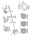
- Fig. 1 is a simplified perspective view of an electrode assembly of a first embodiment of the invention having a coiled, conical tip;
- Fig. 2 is an enlarged end view of the coiled, conical tip of Fig. 1;
- Figs. 2A-2C illustrate electrode assembly tips having an inverted conical shape, a planar serpentine shape and a planar coil shape, respectively;
- Figs. 3A-3D are cross-sectional views of the
electrode assembly taken along
lines 3A-3A through 3D-3D in Fig. 1 respectively; - Fig. 4 is an enlarged cross-sectional view taken along line 4-4 of Fig. 2;
- Fig. 5 is a simplified side view of a steerable delivery catheter used with the electrode assembly of Fig. 1 to create a first embodiment of an electrode array catheter made according to the invention;
- Figs. 6 and 7 are cross-sectional views taken along lines 6-6 and 7-7 of Fig. 5, respectively;
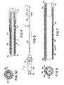
- Fig. 8 is a simplified side view of an alternative embodiment of an electrode array catheter made according to the invention;
- Fig. 8A is an end view of the electrode array of Fig. 8;
- Fig. 9 is an enlarged cross-sectional view of a portion of the tip of the catheter of Fig. 8;
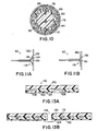
- Fig. 10 is a cross-sectional view taken along line 10-10 of Fig. 9;
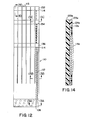
- Figs. 11A and 11B are simplified side views showing deployment of the electrode assembly of Fig. 8 shown with electrode arms engaging a flat surface in partially and fully engaged positions;
- Fig. 12 is a plan view of a flat conductor cable for use with the electrode assembly of Fig. 9 with the proximal terminals with electrode traces shown in dashed lines for one of the electrode arms;
- Figs 13A-13D are cross-sectional views taken
along
lines 13A-13A through 13D-13D of Fig. 12; - Fig. 13E is a cross-sectional view taken along
line 13E-13E of Fig. 13D; and - Fig. 14 illustrates an alternative embodiment of the structure shown in Fig. 13C.
-
- The invention is directed to an electrode array catheter such as shown in Figs. 1-7. An exemplary catheter constructed in accordance with the principles of the present invention includes an electrode assembly 2 which will be described with reference to Figs. 1-4 and a
steerable delivery catheter 4 shown in Figs. 5-7. All dimensions given for each embodiment are exemplary only, and it will be appreciated that specific dimensions may be varied considerably while remaining within the scope of the present invention. - Electrode assembly 2 includes an
electrode catheter body 6 extending from anelectrical connector 8 at a proximal end to atip electrode 10 at a distal end.Body 6, as shown in Figs. 3A and 3B, includes a 0.46 mm (.018 inch) diameter stainlesssteel support mandrel 12 extending fromconnector 8 to atransition region 13 and a 0.31 mm (.015 inch)core 14 extending fromcore transition region 13 to tipelectrode 10. A 0.71 mm (.028 inch) OD/0.51 mm (.020 inch) IDstainless steel hypotube 16 surroundssupport mandrel 12 and an initial portion ofcore 14. See Figs. 3A-3C.Hypotube 16 extends a relatively short distance pastcore transition region 13 and is crimped, as shown in Figs. 3B and 3C, onto the abutting ends ofsupport mandrel 12 andcore 14 attransition region 13. A number, sixteen in the preferred embodiment, ofinsulated conductor wires 18 are located about hypotube 16 within an outerPebax® jacket 20 having a 1.12 mm (.044 inch) ID and a 1.32 mm (.052 inch) OD. Pebax® is the trademark for a polyether block polyamide copolymer made by Elf Atochem, Inc. of Philadelphia, PA. Justpast transition region 13, a smallerPebax® jacket 22 having a 0.79 mm (.031 inch) ID and a 0.94 mm (.037 inch) OD is used.Core 14 is preferably made from a super elastic spring material, such as nickel-titanium alloys (NiTi), such as that available from Furukawa Electric Company Ltd. of Tokyo, Japan. NiTi is preferred forcore 14 because it is very resilient and has a very good spring memory for its prior shape, even when highly flexed. Other highly deformable spring materials, such as spring steel or braided/coiled spring materials, might also be used. - In the embodiment of Figs. 1-4, the
tip 24 of the catheter is made so that it assumes a coiled conical shape as shown in Figs. 1 and 2. Electrode assembly 2, when inserted intodelivery catheter 4, will have itstip 24 in a straightened orientation since it is, prior to deployment, housed withindelivery catheter 4. Only aftertip 24 is moved to its deployed position external ofdelivery catheter 4 will the tip assume its coiled conical shape.Tip 24 can also be made as an inverted coil tip 24a, a planarserpentine tip 24b or aflat coil tip 24c as illustrated in Figs. 2A-2C.Tip 24 includes fifteenelectrodes 26 along its length. Fourteen ofelectrodes 26 are spaced apart by about 0.5-2.0 mm, typically about 1 mm, to form 7 pairs of electrodes.Distal electrode 27 is paired withtip electrode 10, as shown in more detail in Fig. 4 for mapping.NiTi core 14 is seen to be surrounded by apolyimide sleeve 28 having a 0.45 mm (.0179 inch) OD and a 0.40 mm (.0159 inch) ID.Sleeve 28 provides electrical insulation betweencore 14 and theelectrodes 26/conductor wires 18.Conductor wires 18 are electrically connected toelectrodes 26 andtip electrode 10 in the manner indicated in Fig. 4.Tip electrode 10 and theconductor wire 18 connected to the tip electrode are sufficiently heavy duty to permitelectrode 10 to be used as an ablation electrode using RF electrical energy.Tip electrode 10 can also be used for mapping in conjunction withelectrode 27 positioned adjacent the tip electrode. - It may be desired to use electrodes other than
tip electrode 10 for ablation. This may be accommodated by increasing the axial length of selectedelectrodes 26 from about 0.5 mm to 1.0 mm to about 1 to 10 mm. To maintain the desired flexibility oftip 24, the extended length ablation-capable electrodes 26 can be made, for example, as a spiral coil aboutsleeve 28 instead of a band as illustrated in Fig. 4. Also, ablation-capable electrodes 26 could be made of braided material. -
Steerable delivery catheter 4, see Figs. 5-7, is designed for use with electrode assembly 2.Catheter 4 has ahollow interior 30 extending along its entire length from Luer lock fitting 32 at its proximal end to atip ring 34 at its distal end.Catheter 4 includes acatheter body 36 having aPebax® jacket 38 surrounding abraided layer 40. ATFE liner 42 is within braidedlayer 40 and provides a lubricous surface for the passage of electrode assembly 2 withinhollow interior 30 formed withinliner 42. Other lubricious materials, such as FEP, ETFE or PE, could be used instead of TFE forliner 42. -
Hollow interior 30 is formed eccentrically withinTFE liner 42 to provide room for anaxial bore 44 housing a TFE-coatedmanipulator wire 46.Manipulator wire 46 has aball 48 at its distal end which is too large to fit through abore 50 intip ring 34. The proximal end, not shown, of manipulator wire is connected to atip deflection control 52 mounted to ahandle 54. - The distal end of
catheter body 36 includes a deflectingsection 56 distal of ajacket transition line 58. Deflectingsection 56 is less stiff than the proximal end of catheter body to allow deflectingsection 56 to be sufficiently flexible for the proper guidance bywire 46 while providing appropriate structural integrity for the remainder ofcatheter body 36.Tip deflection control 52 is preferably an axially movable type so that pulling oncontrol 52 causes the distal end ofcatheter body 36 to deflect. Other types of controls could be used as well. Also, more than onemanipulator wire 46 could be used. - In use, electrode assembly 2 has its
tip 24 preformed into the coiled, conical shape of Fig. 1.Electrode tip 24 is then inserted through Luer lock fitting 32 and intohollow interior 30. Electrode assembly 2 is continued to be directed throughhollow interior 30 untiltip electrode 10 is just proximal to deflectingsection 56. Using appropriate surgical techniques, the catheter is guided into the heart chamber under consideration. Near the target site to be investigated or treated, electrode assembly 2 is pushed axially and distally untiltip 24 extendspast tip ring 34 and assumes a coiled, conical shape.Tip 24 can then be placed against the chamber wall at the target site under consideration. If desired,tip 24 may be manipulated to deflect laterally and torque the longitudinal axis ofbody 6 prior to being placed against the chamber wall. The flexibility and resilience oftip 24 is such that it will closely conform to the shape of the chamber wall at the target site, whether it be flat, convex, concave, or a combination. This conformance ensures a maximum number ofelectrodes 26 will actually contact the chamber wall. - A separate conductor could be used on
steerable delivery catheter 6 to deliver RF energy for ablation to an electrode mounted as thetip ring 34. It may be possible to do this through the use ofmanipulator wire 46 as both the manipulator wire and as an electrical conductor. - Figs. 8-10 illustrate a second embodiment of the invention.
Electrode array catheter 60 includes asteerable electrode catheter 62 and atubular delivery sheath 64.Catheter 62 passes through and is slidably mounted withintubular delivery sheath 64.Catheter 62 includes ahandle 68 having anelectrical connector 70 at a proximal end, a twist- type, lateral deflection knob 72 and an axially moveabletip deflection control 74.Tip deflection control 74 is connected to amanipulator wire 76 ofelectrode catheter 62; see Figs. 9 and 10. Lateral deflection knob 72 is connected to and is used to rotate acore wire 78 ofcatheter 62.Handle 68 can be of a conventional design. -
Delivery sheath 64 is preferably a three layer sheath having an outer Pebax® layer, a stainless steel braided layer and a TFE liner.Delivery sheath 64 changes its flexibility over its length and includes a proximal,stiffer portion 81 and distal, softer and moreflexible portion 82. The outer surface ofproximal portion 81 preferably has a Durometer reading of about 50 to 80, and more preferably about 70 while thedistal portion 82 preferably has a Durometer reading of about 30 to 50, and more preferably about 35. -
Electrode catheter 62 includes aninsulator body 84, preferably made of PEEK (poly-ether-ether-ketone), housed within thedistal end 86 ofPebax® jacket 80.Insulator body 84 has a threadedtip 88 to which ametal tip electrode 90 is mounted; other mounting structures, such as a snap-fit fitting, could be used instead of threads.Body 84 also includes acentral bore 92 through whichcore wire 78 passes. Threadedtip 88 ofbody 84 has ashallow recess 94 within which thedistal end 96 ofcore 78 is housed.Core wire 78 is secured toinsulator body 84, typically using an adhesive. This provides axial integrity between the ends ofcatheter assembly 60. Rotatingcore wire 78 causes transmission of torque to, and causes the rotation of,electrode catheter 62. -
Body 84 has an additional, radially offset bore 98 through whichmanipulator wire 76 passes.Manipulator wire 76 has anenlarged tip 100 which preventsmanipulator wire 76 from being pulled back through offsetbore 98. This permits the user to deflect the tip ofdelivery sheath 64 when guidingcatheter 60 into position. -
Electrode catheter 62 includes a set ofmapping electrode wires 102, apower electrode wire 104 and a pair ofthermocouple wires 106.Power electrode wire 104 andthermocouple wires 106 pass through bores, not shown, ininsulator body 84 and are connected to tipelectrode 90.Power electrode wire 104 is sufficiently heavy duty to permittip electrode 90 to be used for both ablation using RF electrical energy and for mapping. - The distal ends of
wires 102 are soldered (or otherwise secured to provide electrical conductivity) toproximal terminals 108 formed on a flatflexible circuit 110. Flatflexible circuit 110 is shown in Fig. 12 in its flat configuration prior to being formed into the flared tubular shape of Figs. 8 and 9. With reference to Figs. 12-13E, flatflexible circuit 110 is shown to include a number ofelectrical traces 112 connecting exposedproximal terminals 108 to exposedelectrode pads 114.Flexible circuit 110 has fiveslits 116 extending along substantially the entire length of the circuit so to create sixelectrode elements 118.Electrode elements 118 form a number of axially extending, radially outwardly curved arms havingelectrode pads 114 disposed on their inner surfaces so to contact a chamber wall during use. The electrode arms are preferably 1 mm wide, but could be from 0.1 mm to 2 mm wide, depending on the number of electrodes and traces. The electrode elements (arms) could be made as individual flex circuits rather than a slitted, single circuit.Electrode arms 118 withelectrode pads 114 andelectrode 90 form a petal-like array 119 at the distal end ofelectrode catheter 62.Array 119 has a deployed diameter of about 25 mm; the deployed diameter preferably ranges from about 10 mm to about 100 mm. - Fig. 13A illustrates the exposure of
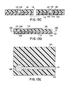
proximal terminals 108 through layers of material which constitutes flatflexible circuit 110. At Fig. 13B, flatflexible circuit 110 is seen to include afirst polyimide layer 120, apolyimide adhesive layer 122 partially surroundingtraces 112 and asecond polyimide layer 124. Fig. 13C-13E are various cross-sectional views taken atelectrode pads 114. The distal ends 126 ofelectrical traces 112 are enlarged and are electrically coupled toelectrode pads 114 by "through-hole plating," a technique where aconductive copper layer 127 covers the walls of ahole 128 formed infirst polyimide layer 120. A thin final plating of gold onelectrode pads 114 enhances biocompatibility. - Fig. 14 illustrates an alternative embodiment of the structure shown in Fig. 13C. A
polyimide sheet layer 120a has single-layer copper electrical traces 112a applied to one surface. Trace 112a is then covered by apolyimide adhesive layer 122a,layer 122a being covered by a secondpolyimide sheet layer 124a. Openings in the cover layer ofpolyimide sheet 124a andadhesive layer 122a expose the enlarged end portions of traces 112a which are selectively plated with copper and then a thin layer of gold to form electrode pads 114a. Pads 114a extend abovesecond sheet layer 124a and serve as the electrodes. Other fabrication techniques are available to those skilled in the art of flexible circuit fabrication. - Figs. 11A and 11B illustrate
array 119 ofelectrode catheter 62 in simplified form witharms 118 pressed against a simulatedheart chamber wall 130. Whilewall 130 is shown as flat, it could be, and typically is, curved in a variety of ways.Arms 118 are shown in Fig. 11A as only slightly flexed from their normal, deployed shape of Fig. 8. The outermost andintermediate electrode pads 11A pads chamber wall 130. Further force onelectrode catheter 62, typically throughcore wire 78, causesarms 118 to further deflect so thatinnermost electrode pads 136 also contactsurface 130 in Fig. 11B. In addition,tip electrode 90 is also in contact withchamber wall 130 in Fig. 11B. -
Electrode pads innermost electrode pads 136 are each paired withtip electrode 90 for mapping purposes.Tip electrode 90 can also be used for ablation whenelectrode catheter 62 is confirmed to be properly positioned at the target site. Much of the preliminary information as to the proper position ofelectrode catheter 62 can be obtained while the electrode catheter is in the partially engaged position of Fig. 11A. In some situations the necessary information for mapping and determining thatelectrode catheter 62 is properly positioned at the target site may require the electrode catheter to be fully engaged withchamber wall 30 as its shown in Fig. 11B. In either case sufficient information is quickly obtained to permitelectrode catheter 62 to be moved, if necessary, to coincide with the target site. - In use,
electrode catheter 62 is housed withindelivery sheath 66 withoutermost electrode pads 132 adjacent the distal end ofsheath 66. Using lateral deflection knob 72 andtip deflection control 74, the distal end ofelectrode array catheter 60 is positioned within the heart chamber and near the target site.Electrode catheter 62 is then moved axially withindelivery sheath 66 to the deployed position of Figs. 8 and 9. This may occur bysheath 66 being retracted back overcatheter 62 or byelectrode catheter 62 being pushed out throughsheath 66.Array 119 can be deflected laterally usingmanipulator wire 76 or torqued (rotated) usingcore wire 78.Arms 118 ofarray 119 are then directed againstchamber wall 130 at what is hoped to be the target site so that mapping can occur. Once it has been determined thattip electrode 90 is properly over the target site to be ablated,electrode catheter 62 can be forced againstchamber wall 130 such as shown in Fig. 11B and the target site ablated by supplying, typically, RF electrical energy to tipelectrode 90 throughpower wire 104. In an alternative embodiment, the distal end ofelectrode array catheter 60 can be deflected laterally or torqued (rotated) by steering the tip of the delivery sheath, which would incorporatemanipulator wire 76 andcore wire 78 and a handle with appropriate controls. - Modification and variation can be made to the disclosed embodiments without departing from the subject of the invention as defined in the following claims. For example, reference has been made to pairs of electrodes for mapping purposes. Electrodes could, of course, be paired in other manners to provide different information. For example, instead of pairing
innermost electrode pad 136 withtip electrode 90, theinnermost electrode pad 136 on onearm 118 could be paired with the corresponding innermost electrode pad on an adjacent arm. Electrode assembly 2 could include a large electrode at the center oftip 24 aligned withbody 6 to permit greater force to be exerted against such enlarged electrode when used for ablation.Flexible circuit 110 could be made by other techniques, such as lamination processes or direct wiring of electrode bands attached to radially disposed arms. Eacharm 118 could be made as a separate flexible circuit instead of being formed by slitting a common circuit as shown in Fig. 12. The number of electrodes for use with the electrode assemblies could vary greatly, from only 4 to 1,000.Electrodes 26 could be paired differently from the closely-spaced bipoles illustrated, such as radially oriented bipoles.Electrode arms 118 could vary in number from 3 to at least 8. In both embodiments a delivery sheath is used to constrain the array of electrodes of the tip prior to deployment at the target site; if the tip can be kept constrained without the need for a delivery sheath, such sheath can be eliminated. Instead of super-elastic NiTi,core 14 could be made of heat-shape memory NiTi. This alloy, also available from Furukawa Electric Co. Ltd., can be used forcore 14 so thattip 24 is flexible but straight below a transition temperature and is flexible and curved, such as illustrated in Figs. 1 and 2A-2C, above the transition temperature. The transition temperature would be chosen so that aftertip 24 is at or near the target site,core 14 could be heated (such as electrically or with a warm saline solution) sotip 24 assumes its predetermined curved shape. Similar heat-shape memory material could be used for electrode elements/arms 118 as well. - The present invention is divided from EP-A-0861676.
Claims (10)
- An electrode array catheter, for insertion into a heart chamber for placement of multiple electrodes against the heart chamber wall in the vicinity of a target site, comprising:an electrode assembly (2) including:a distal end having plurality of resilient, highly flexible arms (118), said arms being radially outwardly curved arms when the distal end is unconstrained; characterized bya plurality of electrodes (132, 134, 136) distributed on said arms (118) so that the electrodes naturally assume a three-dimensional array when said distal end is unconstrained, said electrodes (132, 134, 136) being distributed to be able to contact a limited portion of the chamber wall surrounding the target site.
- The catheter of claim 1 wherein said arms have outer ends unsecured to other structure.
- The catheter of claim 1 or 2 wherein the electrode assembly includes a central electrode.
- The catheter of claim 3 wherein the central electrode is an ablation electrode.
- The catheter of any of claims 1 to 4 further comprising a flexible delivery sheath having a hollow interior, a proximal end and a distal end, the electrode assembly slidably mounted within the hollow interior of the delivery sheath for movement between a retracted position, at least substantially housed within the hollow interior, and a deployed position, extending from the distal end of the delivery sheath.
- The catheter of any of claims 1 to 5 wherein the electrode assembly includes an ablation to electrode.
- The catheter of claim 6 wherein the ablation electrode includes a temperature sensing means.
- The catheter of any of claims 5 to 7 further comprising means for steering the distal end of the electrode assembly within the heart chamber.
- The catheter of claim 8 wherein the steering means includes means for deflecting the distal end of the delivery sheath.
- The catheter of claim 8 wherein the steering means includes means for rotating at least the distal end of the electrode assembly within the delivery sheath.
Applications Claiming Priority (4)
| Application Number | Priority Date | Filing Date | Title |
|---|---|---|---|
| US15062493A | 1993-11-10 | 1993-11-10 | |
| US150624 | 1993-11-10 | ||
| EP98201569A EP0861676B1 (en) | 1993-11-10 | 1994-10-25 | Electrode array catheter |
| EP95901032A EP0728029B1 (en) | 1993-11-10 | 1994-10-25 | Electrode array catheter |
Related Parent Applications (1)
| Application Number | Title | Priority Date | Filing Date |
|---|---|---|---|
| EP98201569A Division EP0861676B1 (en) | 1993-11-10 | 1994-10-25 | Electrode array catheter |
Publications (2)
| Publication Number | Publication Date |
|---|---|
| EP1364677A2 true EP1364677A2 (en) | 2003-11-26 |
| EP1364677A3 EP1364677A3 (en) | 2006-12-27 |
Family
ID=22535350
Family Applications (3)
| Application Number | Title | Priority Date | Filing Date |
|---|---|---|---|
| EP95901032A Expired - Lifetime EP0728029B1 (en) | 1993-11-10 | 1994-10-25 | Electrode array catheter |
| EP03019353A Withdrawn EP1364677A3 (en) | 1993-11-10 | 1994-10-25 | Electrode array catheter |
| EP98201569A Expired - Lifetime EP0861676B1 (en) | 1993-11-10 | 1994-10-25 | Electrode array catheter |
Family Applications Before (1)
| Application Number | Title | Priority Date | Filing Date |
|---|---|---|---|
| EP95901032A Expired - Lifetime EP0728029B1 (en) | 1993-11-10 | 1994-10-25 | Electrode array catheter |
Family Applications After (1)
| Application Number | Title | Priority Date | Filing Date |
|---|---|---|---|
| EP98201569A Expired - Lifetime EP0861676B1 (en) | 1993-11-10 | 1994-10-25 | Electrode array catheter |
Country Status (6)
| Country | Link |
|---|---|
| US (1) | US5938694A (en) |
| EP (3) | EP0728029B1 (en) |
| AU (1) | AU680569B2 (en) |
| CA (1) | CA2176149C (en) |
| DE (2) | DE69419172T2 (en) |
| WO (1) | WO1995013111A1 (en) |
Cited By (8)
| Publication number | Priority date | Publication date | Assignee | Title |
|---|---|---|---|---|
| WO2006044794A3 (en) * | 2004-10-14 | 2006-11-02 | Ablation Frontiers | Ablation catheter |
| US7850685B2 (en) | 2005-06-20 | 2010-12-14 | Medtronic Ablation Frontiers Llc | Ablation catheter |
| US8273084B2 (en) | 2004-11-24 | 2012-09-25 | Medtronic Ablation Frontiers Llc | Atrial ablation catheter and method of use |
| US8617152B2 (en) | 2004-11-15 | 2013-12-31 | Medtronic Ablation Frontiers Llc | Ablation system with feedback |
| US8641704B2 (en) | 2007-05-11 | 2014-02-04 | Medtronic Ablation Frontiers Llc | Ablation therapy system and method for treating continuous atrial fibrillation |
| US8657814B2 (en) | 2005-08-22 | 2014-02-25 | Medtronic Ablation Frontiers Llc | User interface for tissue ablation system |
| US8834461B2 (en) | 2005-07-11 | 2014-09-16 | Medtronic Ablation Frontiers Llc | Low power tissue ablation system |
| US9005194B2 (en) | 2004-11-24 | 2015-04-14 | Medtronic Ablation Frontiers Llc | Atrial ablation catheter adapted for treatment of septal wall arrhythmogenic foci and method of use |
Families Citing this family (275)
| Publication number | Priority date | Publication date | Assignee | Title |
|---|---|---|---|---|
| FR2652928B1 (en) | 1989-10-05 | 1994-07-29 | Diadix Sa | INTERACTIVE LOCAL INTERVENTION SYSTEM WITHIN A AREA OF A NON-HOMOGENEOUS STRUCTURE. |
| WO1994004938A1 (en) | 1992-08-14 | 1994-03-03 | British Telecommunications Public Limited Company | Position location system |
| CA2176149C (en) | 1993-11-10 | 2001-02-27 | Richard S. Jaraczewski | Electrode array catheter |
| US5592939A (en) | 1995-06-14 | 1997-01-14 | Martinelli; Michael A. | Method and system for navigating a catheter probe |
| SE9504334D0 (en) * | 1995-12-04 | 1995-12-04 | Pacesetter Ab | Guidewire assembly |
| SE9504333D0 (en) * | 1995-12-04 | 1995-12-04 | Pacesetter Ab | Guidewire assembly |
| US6839588B1 (en) * | 1997-07-31 | 2005-01-04 | Case Western Reserve University | Electrophysiological cardiac mapping system based on a non-contact non-expandable miniature multi-electrode catheter and method therefor |
| US6226548B1 (en) | 1997-09-24 | 2001-05-01 | Surgical Navigation Technologies, Inc. | Percutaneous registration apparatus and method for use in computer-assisted surgical navigation |
| US6104944A (en) * | 1997-11-17 | 2000-08-15 | Martinelli; Michael A. | System and method for navigating a multiple electrode catheter |
| US6021343A (en) | 1997-11-20 | 2000-02-01 | Surgical Navigation Technologies | Image guided awl/tap/screwdriver |
| US6348058B1 (en) | 1997-12-12 | 2002-02-19 | Surgical Navigation Technologies, Inc. | Image guided spinal surgery guide, system, and method for use thereof |
| US6477400B1 (en) | 1998-08-20 | 2002-11-05 | Sofamor Danek Holdings, Inc. | Fluoroscopic image guided orthopaedic surgery system with intraoperative registration |
| US6544215B1 (en) | 1998-10-02 | 2003-04-08 | Scimed Life Systems, Inc. | Steerable device for introducing diagnostic and therapeutic apparatus into the body |
| US6241665B1 (en) * | 1998-10-21 | 2001-06-05 | Plc Medical System, Inc. | Percutaneous mapping system |
| US6083216A (en) * | 1999-01-05 | 2000-07-04 | Intermedics Inc. | Bent cardiac lead with shape memory torque coil |
| US6470207B1 (en) | 1999-03-23 | 2002-10-22 | Surgical Navigation Technologies, Inc. | Navigational guidance via computer-assisted fluoroscopic imaging |
| US20010007070A1 (en) * | 1999-04-05 | 2001-07-05 | Medtronic, Inc. | Ablation catheter assembly and method for isolating a pulmonary vein |
| US6325797B1 (en) | 1999-04-05 | 2001-12-04 | Medtronic, Inc. | Ablation catheter and method for isolating a pulmonary vein |
| US20050010095A1 (en) * | 1999-04-05 | 2005-01-13 | Medtronic, Inc. | Multi-purpose catheter apparatus and method of use |
| US6702811B2 (en) | 1999-04-05 | 2004-03-09 | Medtronic, Inc. | Ablation catheter assembly with radially decreasing helix and method of use |
| US6491699B1 (en) | 1999-04-20 | 2002-12-10 | Surgical Navigation Technologies, Inc. | Instrument guidance method and system for image guided surgery |
| SE514718C2 (en) † | 1999-06-29 | 2001-04-09 | Jan Otto Solem | Apparatus for treating defective closure of the mitral valve apparatus |
| US7366562B2 (en) | 2003-10-17 | 2008-04-29 | Medtronic Navigation, Inc. | Method and apparatus for surgical navigation |
| US6381485B1 (en) | 1999-10-28 | 2002-04-30 | Surgical Navigation Technologies, Inc. | Registration of human anatomy integrated for electromagnetic localization |
| US6493573B1 (en) | 1999-10-28 | 2002-12-10 | Winchester Development Associates | Method and system for navigating a catheter probe in the presence of field-influencing objects |
| US6499488B1 (en) | 1999-10-28 | 2002-12-31 | Winchester Development Associates | Surgical sensor |
| US8239001B2 (en) | 2003-10-17 | 2012-08-07 | Medtronic Navigation, Inc. | Method and apparatus for surgical navigation |
| US6474341B1 (en) | 1999-10-28 | 2002-11-05 | Surgical Navigation Technologies, Inc. | Surgical communication and power system |
| US8644907B2 (en) | 1999-10-28 | 2014-02-04 | Medtronic Navigaton, Inc. | Method and apparatus for surgical navigation |
| US11331150B2 (en) | 1999-10-28 | 2022-05-17 | Medtronic Navigation, Inc. | Method and apparatus for surgical navigation |
| US20040215235A1 (en) * | 1999-11-16 | 2004-10-28 | Barrx, Inc. | Methods and systems for determining physiologic characteristics for treatment of the esophagus |
| WO2001035846A1 (en) | 1999-11-16 | 2001-05-25 | Ganz Robert A | System and method of treating abnormal tissue in the human esophagus |
| US20060095032A1 (en) | 1999-11-16 | 2006-05-04 | Jerome Jackson | Methods and systems for determining physiologic characteristics for treatment of the esophagus |
| US6745080B2 (en) | 1999-11-22 | 2004-06-01 | Scimed Life Systems, Inc. | Helical and pre-oriented loop structures for supporting diagnostic and therapeutic elements in contact with body tissue |
| JP4558251B2 (en) * | 1999-11-22 | 2010-10-06 | ボストン サイエンティフィック リミテッド | Loop structure for supporting diagnostic and therapeutic elements in contact with body tissue |
| US6711444B2 (en) | 1999-11-22 | 2004-03-23 | Scimed Life Systems, Inc. | Methods of deploying helical diagnostic and therapeutic element supporting structures within the body |
| US7570982B2 (en) * | 2000-01-27 | 2009-08-04 | Biosense Webster, Inc. | Catheter having mapping assembly |
| US6795721B2 (en) | 2000-01-27 | 2004-09-21 | Biosense Webster, Inc. | Bidirectional catheter having mapping assembly |
| US6628976B1 (en) * | 2000-01-27 | 2003-09-30 | Biosense Webster, Inc. | Catheter having mapping assembly |
| US6711428B2 (en) * | 2000-01-27 | 2004-03-23 | Biosense Webster, Inc. | Catheter having mapping assembly |
| WO2001064124A1 (en) | 2000-03-01 | 2001-09-07 | Surgical Navigation Technologies, Inc. | Multiple cannula image guided tool for image guided procedures |
| US6536949B1 (en) * | 2000-03-07 | 2003-03-25 | Richard R. Heuser | Catheter for thermal evaluation of arteriosclerotic plaque |
| US6535756B1 (en) | 2000-04-07 | 2003-03-18 | Surgical Navigation Technologies, Inc. | Trajectory storage apparatus and method for surgical navigation system |
| US6456889B2 (en) | 2000-05-15 | 2002-09-24 | Pacesetter, Inc. | Lead with polymeric tubular liner for guidewire and stylet insertion |
| US6456890B2 (en) | 2000-05-15 | 2002-09-24 | Pacesetter, Inc. | Lead with polymeric tubular liner for guidewire and stylet insertion |
| US7085400B1 (en) | 2000-06-14 | 2006-08-01 | Surgical Navigation Technologies, Inc. | System and method for image based sensor calibration |
| US6746446B1 (en) | 2000-08-04 | 2004-06-08 | Cardima, Inc. | Electrophysiological device for the isthmus |
| US6669692B1 (en) * | 2000-08-21 | 2003-12-30 | Biosense Webster, Inc. | Ablation catheter with cooled linear electrode |
| US6926669B1 (en) * | 2000-10-10 | 2005-08-09 | Medtronic, Inc. | Heart wall ablation/mapping catheter and method |
| EP1201198A1 (en) * | 2000-10-27 | 2002-05-02 | MicroNet Medical, Inc. | Catheter with thin film electrodes and method for making same |
| IT1315053B1 (en) * | 2000-11-10 | 2003-01-27 | Thermo Med 2000 Kft | NEEDLE-ELECTRODE WITH RADIOFREQUENCY ACTIVE FILAMENT |
| US6728563B2 (en) | 2000-11-29 | 2004-04-27 | St. Jude Medical, Daig Division, Inc. | Electrophysiology/ablation catheter having “halo” configuration |
| US7081114B2 (en) * | 2000-11-29 | 2006-07-25 | St. Jude Medical, Atrial Fibrillation Division, Inc. | Electrophysiology/ablation catheter having lariat configuration of variable radius |
| US6659981B2 (en) | 2000-12-08 | 2003-12-09 | Medtronic, Inc. | Medical device delivery catheter with distal locator |
| US6540733B2 (en) | 2000-12-29 | 2003-04-01 | Corazon Technologies, Inc. | Proton generating catheters and methods for their use in enhancing fluid flow through a vascular site occupied by a calcified vascular occlusion |
| US6564096B2 (en) | 2001-02-28 | 2003-05-13 | Robert A. Mest | Method and system for treatment of tachycardia and fibrillation |
| US6909920B2 (en) * | 2001-04-27 | 2005-06-21 | Medtronic, Inc. | System and method for positioning an implantable medical device within a body |
| DE60223794T2 (en) * | 2001-04-27 | 2008-10-30 | C.R. Bard, Inc. | ELECTROPHYSIOLOGY CATHETERS FOR MAPPING AND ABLATION |
| US6972016B2 (en) * | 2001-05-01 | 2005-12-06 | Cardima, Inc. | Helically shaped electrophysiology catheter |
| US7175734B2 (en) * | 2001-05-03 | 2007-02-13 | Medtronic, Inc. | Porous medical catheter and methods of manufacture |
| US6636757B1 (en) | 2001-06-04 | 2003-10-21 | Surgical Navigation Technologies, Inc. | Method and apparatus for electromagnetic navigation of a surgical probe near a metal object |
| US6671533B2 (en) * | 2001-10-11 | 2003-12-30 | Irvine Biomedical Inc. | System and method for mapping and ablating body tissue of the interior region of the heart |
| US8974446B2 (en) | 2001-10-11 | 2015-03-10 | St. Jude Medical, Inc. | Ultrasound ablation apparatus with discrete staggered ablation zones |
| US20070038056A1 (en) | 2001-10-11 | 2007-02-15 | Carlo Pappone | System and methods for locating and ablating arrhythomogenic tissues |
| US7785324B2 (en) | 2005-02-25 | 2010-08-31 | Endoscopic Technologies, Inc. (Estech) | Clamp based lesion formation apparatus and methods configured to protect non-target tissue |
| US7753908B2 (en) | 2002-02-19 | 2010-07-13 | Endoscopic Technologies, Inc. (Estech) | Apparatus for securing an electrophysiology probe to a clamp |
| US7591818B2 (en) | 2001-12-04 | 2009-09-22 | Endoscopic Technologies, Inc. | Cardiac ablation devices and methods |
| US7399300B2 (en) * | 2001-12-04 | 2008-07-15 | Endoscopic Technologies, Inc. | Cardiac ablation devices and methods |
| US20030105505A1 (en) * | 2001-12-05 | 2003-06-05 | Pianca Anne M. | Medical leads with superior handling characteristics |
| US6961602B2 (en) * | 2001-12-31 | 2005-11-01 | Biosense Webster, Inc. | Catheter having multiple spines each having electrical mapping and location sensing capabilities |
| US6932816B2 (en) * | 2002-02-19 | 2005-08-23 | Boston Scientific Scimed, Inc. | Apparatus for converting a clamp into an electrophysiology device |
| US6947786B2 (en) | 2002-02-28 | 2005-09-20 | Surgical Navigation Technologies, Inc. | Method and apparatus for perspective inversion |
| US6733499B2 (en) * | 2002-02-28 | 2004-05-11 | Biosense Webster, Inc. | Catheter having circular ablation assembly |
| US6889091B2 (en) | 2002-03-06 | 2005-05-03 | Medtronic, Inc. | Method and apparatus for placing a coronary sinus/cardiac vein pacing lead using a multi-purpose side lumen |
| US6990368B2 (en) | 2002-04-04 | 2006-01-24 | Surgical Navigation Technologies, Inc. | Method and apparatus for virtual digital subtraction angiography |
| US7653438B2 (en) | 2002-04-08 | 2010-01-26 | Ardian, Inc. | Methods and apparatus for renal neuromodulation |
| US8774913B2 (en) | 2002-04-08 | 2014-07-08 | Medtronic Ardian Luxembourg S.A.R.L. | Methods and apparatus for intravasculary-induced neuromodulation |
| US20140018880A1 (en) | 2002-04-08 | 2014-01-16 | Medtronic Ardian Luxembourg S.A.R.L. | Methods for monopolar renal neuromodulation |
| US6974455B2 (en) | 2002-04-10 | 2005-12-13 | Boston Scientific Scimed, Inc. | Auto advancing radio frequency array |
| US7998062B2 (en) | 2004-03-29 | 2011-08-16 | Superdimension, Ltd. | Endoscope structures and techniques for navigating to a target in branched structure |
| ITBS20020046U1 (en) * | 2002-04-23 | 2003-10-23 | Fogazzi Di Venturelli Andrea & | INSTRUMENT WITH AT LEAST TWO RADIOFREQUENCY ACTIVE FILAMENTS FOR TREATMENT OF CANCER |
| US6866662B2 (en) | 2002-07-23 | 2005-03-15 | Biosense Webster, Inc. | Ablation catheter having stabilizing array |
| US7089045B2 (en) * | 2002-08-30 | 2006-08-08 | Biosense Webster, Inc. | Catheter and method for mapping Purkinje fibers |
| US8229572B2 (en) | 2008-06-27 | 2012-07-24 | Medtronic, Inc. | Lead delivery device and method |
| US7107105B2 (en) * | 2002-09-24 | 2006-09-12 | Medtronic, Inc. | Deployable medical lead fixation system and method |
| US9636499B2 (en) | 2002-09-24 | 2017-05-02 | Medtronic, Inc. | Lead delivery device and method |
| US9480839B2 (en) | 2002-09-24 | 2016-11-01 | Medtronic, Inc. | Lead delivery device and method |
| US9849279B2 (en) | 2008-06-27 | 2017-12-26 | Medtronic, Inc. | Lead delivery device and method |
| US8920432B2 (en) | 2002-09-24 | 2014-12-30 | Medtronic, Inc. | Lead delivery device and method |
| US20040082947A1 (en) | 2002-10-25 | 2004-04-29 | The Regents Of The University Of Michigan | Ablation catheters |
| US20060241366A1 (en) * | 2002-10-31 | 2006-10-26 | Gary Falwell | Electrophysiology loop catheter |
| US7697972B2 (en) | 2002-11-19 | 2010-04-13 | Medtronic Navigation, Inc. | Navigation system for cardiac therapies |
| US7599730B2 (en) | 2002-11-19 | 2009-10-06 | Medtronic Navigation, Inc. | Navigation system for cardiac therapies |
| US6695609B1 (en) * | 2002-12-06 | 2004-02-24 | John Zink Company, Llc | Compact low NOx gas burner apparatus and methods |
| US6984232B2 (en) | 2003-01-17 | 2006-01-10 | St. Jude Medical, Daig Division, Inc. | Ablation catheter assembly having a virtual electrode comprising portholes |
| US7819866B2 (en) | 2003-01-21 | 2010-10-26 | St. Jude Medical, Atrial Fibrillation Division, Inc. | Ablation catheter and electrode |
| US7387629B2 (en) * | 2003-01-21 | 2008-06-17 | St. Jude Medical, Atrial Fibrillation Division, Inc. | Catheter design that facilitates positioning at tissue to be diagnosed or treated |
| US6960207B2 (en) * | 2003-01-21 | 2005-11-01 | St Jude Medical, Daig Division, Inc. | Ablation catheter having a virtual electrode comprising portholes and a porous conductor |
| US7166088B2 (en) | 2003-01-27 | 2007-01-23 | Heuser Richard R | Catheter introducer system |
| US7542791B2 (en) | 2003-01-30 | 2009-06-02 | Medtronic Navigation, Inc. | Method and apparatus for preplanning a surgical procedure |
| US7660623B2 (en) | 2003-01-30 | 2010-02-09 | Medtronic Navigation, Inc. | Six degree of freedom alignment display for medical procedures |
| US6923808B2 (en) | 2003-02-24 | 2005-08-02 | Boston Scientific Scimed, Inc. | Probes having helical and loop shaped inflatable therapeutic elements |
| US7142903B2 (en) | 2003-03-12 | 2006-11-28 | Biosense Webster, Inc. | Catheter with contractable mapping assembly |
| US20040186467A1 (en) * | 2003-03-21 | 2004-09-23 | Swanson David K. | Apparatus for maintaining contact between diagnostic and therapeutic elements and tissue and systems including the same |
| US7497857B2 (en) | 2003-04-29 | 2009-03-03 | Medtronic, Inc. | Endocardial dispersive electrode for use with a monopolar RF ablation pen |
| US7003342B2 (en) * | 2003-06-02 | 2006-02-21 | Biosense Webster, Inc. | Catheter and method for mapping a pulmonary vein |
| US7818048B2 (en) | 2003-06-02 | 2010-10-19 | Biosense Webster, Inc. | Catheter and method for mapping a pulmonary vein |
| US7101362B2 (en) * | 2003-07-02 | 2006-09-05 | St. Jude Medical, Atrial Fibrillation Division, Inc. | Steerable and shapable catheter employing fluid force |
| CA2532815A1 (en) * | 2003-07-11 | 2005-01-27 | Steven A. Daniel | Thermal ablation of biological tissue |
| US10182734B2 (en) * | 2003-07-18 | 2019-01-22 | Biosense Webster, Inc. | Enhanced ablation and mapping catheter and method for treating atrial fibrillation |
| US7313430B2 (en) | 2003-08-28 | 2007-12-25 | Medtronic Navigation, Inc. | Method and apparatus for performing stereotactic surgery |
| WO2005025635A2 (en) | 2003-09-15 | 2005-03-24 | Super Dimension Ltd. | System of accessories for use with bronchoscopes |
| EP2316328B1 (en) | 2003-09-15 | 2012-05-09 | Super Dimension Ltd. | Wrap-around holding device for use with bronchoscopes |
| US7835778B2 (en) | 2003-10-16 | 2010-11-16 | Medtronic Navigation, Inc. | Method and apparatus for surgical navigation of a multiple piece construct for implantation |
| US7840253B2 (en) | 2003-10-17 | 2010-11-23 | Medtronic Navigation, Inc. | Method and apparatus for surgical navigation |
| WO2005039696A1 (en) * | 2003-10-21 | 2005-05-06 | The Regents Of The University Of Michigan | Intracranial neural interface system |
| US7155270B2 (en) * | 2003-10-24 | 2006-12-26 | Biosense Webster, Inc. | Catheter with multi-spine mapping assembly |
| US7179256B2 (en) * | 2003-10-24 | 2007-02-20 | Biosense Webster, Inc. | Catheter with ablation needle and mapping assembly |
| US7666203B2 (en) | 2003-11-06 | 2010-02-23 | Nmt Medical, Inc. | Transseptal puncture apparatus |
| US8292910B2 (en) | 2003-11-06 | 2012-10-23 | Pressure Products Medical Supplies, Inc. | Transseptal puncture apparatus |
| US8052676B2 (en) | 2003-12-02 | 2011-11-08 | Boston Scientific Scimed, Inc. | Surgical methods and apparatus for stimulating tissue |
| US7608072B2 (en) * | 2003-12-02 | 2009-10-27 | Boston Scientific Scimed, Inc. | Surgical methods and apparatus for maintaining contact between tissue and electrophysiology elements and confirming whether a therapeutic lesion has been formed |
| US20050119653A1 (en) * | 2003-12-02 | 2005-06-02 | Swanson David K. | Surgical methods and apparatus for forming lesions in tissue and confirming whether a therapeutic lesion has been formed |
| US8002770B2 (en) | 2003-12-02 | 2011-08-23 | Endoscopic Technologies, Inc. (Estech) | Clamp based methods and apparatus for forming lesions in tissue and confirming whether a therapeutic lesion has been formed |
| US20050137646A1 (en) | 2003-12-22 | 2005-06-23 | Scimed Life Systems, Inc. | Method of intravascularly delivering stimulation leads into brain |
| US7150745B2 (en) | 2004-01-09 | 2006-12-19 | Barrx Medical, Inc. | Devices and methods for treatment of luminal tissue |
| US8764725B2 (en) | 2004-02-09 | 2014-07-01 | Covidien Lp | Directional anchoring mechanism, method and applications thereof |
| US7371233B2 (en) * | 2004-02-19 | 2008-05-13 | Boston Scientific Scimed, Inc. | Cooled probes and apparatus for maintaining contact between cooled probes and tissue |
| US20050203600A1 (en) | 2004-03-12 | 2005-09-15 | Scimed Life Systems, Inc. | Collapsible/expandable tubular electrode leads |
| US7590454B2 (en) | 2004-03-12 | 2009-09-15 | Boston Scientific Neuromodulation Corporation | Modular stimulation lead network |
| US8007495B2 (en) | 2004-03-31 | 2011-08-30 | Biosense Webster, Inc. | Catheter for circumferential ablation at or near a pulmonary vein |
| US8216216B2 (en) * | 2004-04-19 | 2012-07-10 | Boston Scientific Scimed, Inc. | Ablation devices with sensor structures |
| US7567834B2 (en) | 2004-05-03 | 2009-07-28 | Medtronic Navigation, Inc. | Method and apparatus for implantation between two vertebral bodies |
| US8412348B2 (en) | 2004-05-06 | 2013-04-02 | Boston Scientific Neuromodulation Corporation | Intravascular self-anchoring integrated tubular electrode body |
| EP1753496A1 (en) | 2004-05-17 | 2007-02-21 | C.R.Bard, Inc. | Articulated catheter |
| US7286879B2 (en) | 2004-07-16 | 2007-10-23 | Boston Scientific Scimed, Inc. | Method of stimulating fastigium nucleus to treat neurological disorders |
| JP4846720B2 (en) * | 2004-08-12 | 2011-12-28 | メドトロニック,インコーポレイテッド | Catheter apparatus for treating cardiac arrhythmia |
| US8545418B2 (en) | 2004-08-25 | 2013-10-01 | Richard R. Heuser | Systems and methods for ablation of occlusions within blood vessels |
| US7549988B2 (en) | 2004-08-30 | 2009-06-23 | Boston Scientific Scimed, Inc. | Hybrid lesion formation apparatus, systems and methods |
| US8409191B2 (en) * | 2004-11-04 | 2013-04-02 | Boston Scientific Scimed, Inc. | Preshaped ablation catheter for ablating pulmonary vein ostia within the heart |
| US7937160B2 (en) | 2004-12-10 | 2011-05-03 | Boston Scientific Neuromodulation Corporation | Methods for delivering cortical electrode leads into patient's head |
| US7727231B2 (en) | 2005-01-08 | 2010-06-01 | Boston Scientific Scimed, Inc. | Apparatus and methods for forming lesions in tissue and applying stimulation energy to tissue in which lesions are formed |
| WO2006078863A2 (en) * | 2005-01-18 | 2006-07-27 | Daniel Steven A | Device and method for thermal ablation of biological tissue using spherical ablation patterns |
| US7892228B2 (en) * | 2005-02-25 | 2011-02-22 | Boston Scientific Scimed, Inc. | Dual mode lesion formation apparatus, systems and methods |
| CA2599976A1 (en) * | 2005-03-04 | 2006-09-08 | Cathrx Ltd | A catheter handle and a catheter assembly including such a handle |
| CA2600277A1 (en) * | 2005-03-04 | 2006-09-08 | Cathrx Ltd | A catheter handle and a catheter assembly including such a handle |
| US9320564B2 (en) * | 2005-05-05 | 2016-04-26 | Boston Scientific Scimed Inc. | Steerable catheter and method for performing medical procedure adjacent pulmonary vein ostia |
| US8016822B2 (en) | 2005-05-28 | 2011-09-13 | Boston Scientific Scimed, Inc. | Fluid injecting devices and methods and apparatus for maintaining contact between fluid injecting devices and tissue |
| US9014796B2 (en) | 2005-06-14 | 2015-04-21 | Regents Of The University Of Michigan | Flexible polymer microelectrode with fluid delivery capability and methods for making same |
| US7819868B2 (en) | 2005-06-21 | 2010-10-26 | St. Jude Medical, Atrial Fibrilation Division, Inc. | Ablation catheter with fluid distribution structures |
| US8945151B2 (en) * | 2005-07-13 | 2015-02-03 | Atricure, Inc. | Surgical clip applicator and apparatus including the same |
| US9259267B2 (en) | 2005-09-06 | 2016-02-16 | W.L. Gore & Associates, Inc. | Devices and methods for treating cardiac tissue |
| US20070055229A1 (en) * | 2005-09-06 | 2007-03-08 | Kladakis Stephanie M | In tunnel electrode for sealing intracardiac defects |
| US7835784B2 (en) | 2005-09-21 | 2010-11-16 | Medtronic Navigation, Inc. | Method and apparatus for positioning a reference frame |
| EP1931419B1 (en) * | 2005-10-07 | 2016-08-10 | NeuroNexus Technologies, Inc. | Modular multichannel microelectrode array |
| US7997278B2 (en) | 2005-11-23 | 2011-08-16 | Barrx Medical, Inc. | Precision ablating method |
| US8702694B2 (en) | 2005-11-23 | 2014-04-22 | Covidien Lp | Auto-aligning ablating device and method of use |
| US7959627B2 (en) * | 2005-11-23 | 2011-06-14 | Barrx Medical, Inc. | Precision ablating device |
| US9168102B2 (en) | 2006-01-18 | 2015-10-27 | Medtronic Navigation, Inc. | Method and apparatus for providing a container to a sterile environment |
| US8062321B2 (en) | 2006-01-25 | 2011-11-22 | Pq Bypass, Inc. | Catheter system for connecting adjacent blood vessels |
| US8195267B2 (en) | 2006-01-26 | 2012-06-05 | Seymour John P | Microelectrode with laterally extending platform for reduction of tissue encapsulation |
| ATE534430T1 (en) * | 2006-01-31 | 2011-12-15 | St Jude Medical | IMPLANTABLE CARDIAC STIMULATOR, DEVICE AND SYSTEM FOR MONITORING THE STATUS OF A CARDIAC CONDUCT |
| US8112292B2 (en) | 2006-04-21 | 2012-02-07 | Medtronic Navigation, Inc. | Method and apparatus for optimizing a therapy |
| US8135476B2 (en) | 2006-04-27 | 2012-03-13 | Medtronic, Inc. | Implantable medical electrical stimulation lead fixation method and apparatus |
| US8145323B2 (en) | 2006-04-27 | 2012-03-27 | Medtronic, Inc. | Implantable medical electrical stimulation lead fixation method and apparatus |
| US8204569B2 (en) | 2006-04-27 | 2012-06-19 | Medtronic, Inc. | Implantable medical electrical stimulation lead fixation method and apparatus |
| US8200343B2 (en) | 2006-04-27 | 2012-06-12 | Medtronic, Inc. | Implantable medical electrical stimulation lead fixation method and apparatus |
| US7774051B2 (en) | 2006-05-17 | 2010-08-10 | St. Jude Medical, Atrial Fibrillation Division, Inc. | System and method for mapping electrophysiology information onto complex geometry |
| AU2007216661A1 (en) * | 2006-09-21 | 2008-04-10 | Cathrx Ltd | Catheter actuator |
| US8660635B2 (en) | 2006-09-29 | 2014-02-25 | Medtronic, Inc. | Method and apparatus for optimizing a computer assisted surgical procedure |
| WO2008045877A2 (en) * | 2006-10-10 | 2008-04-17 | St. Jude Medical, Atrial Fibrillation Division, Inc. | Electrode tip and ablation system |
| US20080147040A1 (en) * | 2006-12-13 | 2008-06-19 | Medtronic Vascular, Inc. A Delaware Corporation | Catheters Having Linear Electrode Arrays and Their Methods of Use |
| US8909341B2 (en) * | 2007-01-22 | 2014-12-09 | Respicardia, Inc. | Device and method for the treatment of breathing disorders and cardiac disorders |
| US8731673B2 (en) * | 2007-02-26 | 2014-05-20 | Sapiens Steering Brain Stimulation B.V. | Neural interface system |
| US8744599B2 (en) * | 2007-03-09 | 2014-06-03 | St. Jude Medical, Atrial Fibrillation Division, Inc. | High density mapping catheter |
| US7706891B2 (en) * | 2007-03-21 | 2010-04-27 | St. Jude Medical, Atrial Fibrillation Division, Inc. | Catheter employing shape memory alloy shaping wire or pull wire and method of its manufacture |
| WO2008137757A1 (en) | 2007-05-04 | 2008-11-13 | Barrx Medical, Inc. | Method and apparatus for gastrointestinal tract ablation for treatment of obesity |
| AU2008202483B2 (en) * | 2007-06-15 | 2011-07-14 | Cathrx Ltd | A deflectable stylet |
| US8784338B2 (en) * | 2007-06-22 | 2014-07-22 | Covidien Lp | Electrical means to normalize ablational energy transmission to a luminal tissue surface of varying size |
| US9987488B1 (en) | 2007-06-27 | 2018-06-05 | Respicardia, Inc. | Detecting and treating disordered breathing |
| KR101513926B1 (en) | 2007-07-06 | 2015-04-21 | 코비디엔 엘피 | Ablation in the gastrointestinal tract to achieve hemostasis and eradicate lesions with a propensity for bleeding |
| WO2009009443A1 (en) * | 2007-07-06 | 2009-01-15 | Barrx Medical, Inc. | Method and apparatus for gastrointestinal tract ablation to achieve loss of persistent and/or recurrent excess body weight following a weight-loss operation |
| US8646460B2 (en) * | 2007-07-30 | 2014-02-11 | Covidien Lp | Cleaning device and methods |
| US8273012B2 (en) | 2007-07-30 | 2012-09-25 | Tyco Healthcare Group, Lp | Cleaning device and methods |
| WO2009022537A1 (en) * | 2007-08-11 | 2009-02-19 | Japan Lifeline Co., Ltd. | Electrode catheter |
| JP4925206B2 (en) * | 2007-08-11 | 2012-04-25 | 日本ライフライン株式会社 | Electrode catheter |
| JP4925210B2 (en) * | 2007-09-29 | 2012-04-25 | 日本ライフライン株式会社 | Electrode catheter |
| US8905920B2 (en) | 2007-09-27 | 2014-12-09 | Covidien Lp | Bronchoscope adapter and method |
| US8224417B2 (en) * | 2007-10-17 | 2012-07-17 | Neuronexus Technologies, Inc. | Guide tube for an implantable device system |
| US8958862B2 (en) | 2007-10-17 | 2015-02-17 | Neuronexus Technologies, Inc. | Implantable device including a resorbable carrier |
| US8565894B2 (en) * | 2007-10-17 | 2013-10-22 | Neuronexus Technologies, Inc. | Three-dimensional system of electrode leads |
| US8500731B2 (en) * | 2007-12-21 | 2013-08-06 | St. Jude Medical, Atrial Fibrillation Division, Inc. | Adjustable length flexible polymer electrode catheter and method for ablation |
| US8103327B2 (en) | 2007-12-28 | 2012-01-24 | Rhythmia Medical, Inc. | Cardiac mapping catheter |
| US8122594B2 (en) | 2007-12-31 | 2012-02-28 | St. Jude Medical, Atrial Fibrillation Division, Inc. | Method of manufacturing a deflectable electrophysiological catheter |
| US9199075B1 (en) | 2008-02-07 | 2015-12-01 | Respicardia, Inc. | Transvascular medical lead |
| US8498720B2 (en) | 2008-02-29 | 2013-07-30 | Neuronexus Technologies, Inc. | Implantable electrode and method of making the same |
| US20090240314A1 (en) * | 2008-03-24 | 2009-09-24 | Kong K C | Implantable electrode lead system with a three dimensional arrangement and method of making the same |
| US9289142B2 (en) | 2008-03-24 | 2016-03-22 | Neuronexus Technologies, Inc. | Implantable electrode lead system with a three dimensional arrangement and method of making the same |
| US9575140B2 (en) | 2008-04-03 | 2017-02-21 | Covidien Lp | Magnetic interference detection system and method |
| EP2297673B1 (en) | 2008-06-03 | 2020-04-22 | Covidien LP | Feature-based registration method |
| US8218847B2 (en) | 2008-06-06 | 2012-07-10 | Superdimension, Ltd. | Hybrid registration method |
| US20090318914A1 (en) * | 2008-06-18 | 2009-12-24 | Utley David S | System and method for ablational treatment of uterine cervical neoplasia |
| US11931523B2 (en) | 2008-06-27 | 2024-03-19 | Medtronic, Inc. | Lead delivery device and method |
| US9775990B2 (en) | 2008-06-27 | 2017-10-03 | Medtronic, Inc. | Lead delivery device and method |
| US9775989B2 (en) | 2008-06-27 | 2017-10-03 | Medtronic, Inc. | Lead delivery device and method |
| US8932207B2 (en) | 2008-07-10 | 2015-01-13 | Covidien Lp | Integrated multi-functional endoscopic tool |
| US8165658B2 (en) | 2008-09-26 | 2012-04-24 | Medtronic, Inc. | Method and apparatus for positioning a guide relative to a base |
| WO2010048676A1 (en) * | 2008-10-31 | 2010-05-06 | Cathrx Ltd | A catheter assembly |
| US20100125281A1 (en) * | 2008-11-17 | 2010-05-20 | Northwestern University | Cardiac pacing lead and delivery sheath |
| US8175681B2 (en) | 2008-12-16 | 2012-05-08 | Medtronic Navigation Inc. | Combination of electromagnetic and electropotential localization |
| US8600472B2 (en) | 2008-12-30 | 2013-12-03 | Biosense Webster (Israel), Ltd. | Dual-purpose lasso catheter with irrigation using circumferentially arranged ring bump electrodes |
| US8475450B2 (en) | 2008-12-30 | 2013-07-02 | Biosense Webster, Inc. | Dual-purpose lasso catheter with irrigation |
| US8372033B2 (en) | 2008-12-31 | 2013-02-12 | St. Jude Medical, Atrial Fibrillation Division, Inc. | Catheter having proximal heat sensitive deflection mechanism and related methods of use and manufacturing |
| US8611984B2 (en) | 2009-04-08 | 2013-12-17 | Covidien Lp | Locatable catheter |
| US8929969B2 (en) * | 2009-04-14 | 2015-01-06 | Medtronic Ablation Frontiers Llc | Catheter assembly and associated method |
| US8494613B2 (en) | 2009-08-31 | 2013-07-23 | Medtronic, Inc. | Combination localization system |
| US8494614B2 (en) | 2009-08-31 | 2013-07-23 | Regents Of The University Of Minnesota | Combination localization system |
| US8233987B2 (en) | 2009-09-10 | 2012-07-31 | Respicardia, Inc. | Respiratory rectification |
| US9468755B2 (en) | 2009-09-30 | 2016-10-18 | Respicardia, Inc. | Medical lead with preformed bias |
| EP2488098B1 (en) * | 2009-10-16 | 2014-03-19 | Neuronexus Technologies | Neural interface system |
| CN102686147B (en) * | 2009-11-05 | 2016-01-20 | 格雷特巴奇有限公司 | waveguide neural interface device |
| US8920415B2 (en) | 2009-12-16 | 2014-12-30 | Biosense Webster (Israel) Ltd. | Catheter with helical electrode |
| US8608735B2 (en) * | 2009-12-30 | 2013-12-17 | Biosense Webster (Israel) Ltd. | Catheter with arcuate end section |
| DE102010019648B4 (en) * | 2010-05-06 | 2019-07-11 | Acandis Gmbh | Electrode and method for producing such an electrode |
| WO2011159834A1 (en) | 2010-06-15 | 2011-12-22 | Superdimension, Ltd. | Locatable expandable working channel and method |
| US9155861B2 (en) | 2010-09-20 | 2015-10-13 | Neuronexus Technologies, Inc. | Neural drug delivery system with fluidic threads |
| EP2632378B1 (en) | 2010-10-25 | 2018-10-17 | Medtronic Ardian Luxembourg S.à.r.l. | Catheter apparatuses having multi-electrode arrays for renal neuromodulation and associated systems |
| US10278774B2 (en) | 2011-03-18 | 2019-05-07 | Covidien Lp | Selectively expandable operative element support structure and methods of use |
| US9220433B2 (en) * | 2011-06-30 | 2015-12-29 | Biosense Webster (Israel), Ltd. | Catheter with variable arcuate distal section |
| US9662169B2 (en) | 2011-07-30 | 2017-05-30 | Biosense Webster (Israel) Ltd. | Catheter with flow balancing valve |
| US9592091B2 (en) * | 2011-08-30 | 2017-03-14 | Biosense Webster (Israel) Ltd. | Ablation catheter for vein anatomies |
| US8498686B2 (en) | 2011-10-04 | 2013-07-30 | Biosense Webster (Israel), Ltd. | Mapping catheter with spiral electrode assembly |
| US9314299B2 (en) | 2012-03-21 | 2016-04-19 | Biosense Webster (Israel) Ltd. | Flower catheter for mapping and ablating veinous and other tubular locations |
| US9821145B2 (en) | 2012-03-23 | 2017-11-21 | Pressure Products Medical Supplies Inc. | Transseptal puncture apparatus and method for using the same |
| JP2013202241A (en) * | 2012-03-29 | 2013-10-07 | Japan Lifeline Co Ltd | Electrode catheter |
| US9717555B2 (en) * | 2012-05-14 | 2017-08-01 | Biosense Webster (Israel), Ltd. | Catheter with helical end section for vessel ablation |
| CA2872189A1 (en) | 2012-05-11 | 2013-11-14 | William W. CHANG | Multi-electrode catheter assemblies for renal neuromodulation and associated systems and methods |
| US9408571B2 (en) | 2012-06-18 | 2016-08-09 | Carnegie Mellon University | Apparatus and method for implantation of devices into soft tissue |
| US9827036B2 (en) | 2012-11-13 | 2017-11-28 | Pulnovo Medical (Wuxi) Co., Ltd. | Multi-pole synchronous pulmonary artery radiofrequency ablation catheter |
| CN102908191A (en) | 2012-11-13 | 2013-02-06 | 陈绍良 | Multipolar synchronous pulmonary artery radiofrequency ablation catheter |
| US11241267B2 (en) | 2012-11-13 | 2022-02-08 | Pulnovo Medical (Wuxi) Co., Ltd | Multi-pole synchronous pulmonary artery radiofrequency ablation catheter |
| US9095321B2 (en) | 2012-11-21 | 2015-08-04 | Medtronic Ardian Luxembourg S.A.R.L. | Cryotherapeutic devices having integral multi-helical balloons and methods of making the same |
| US20140257130A1 (en) * | 2013-03-11 | 2014-09-11 | Boston Scientific Scimed, Inc. | Powered pull wire design for ablation catheters |
| US9179974B2 (en) | 2013-03-15 | 2015-11-10 | Medtronic Ardian Luxembourg S.A.R.L. | Helical push wire electrode |
| US20150073515A1 (en) | 2013-09-09 | 2015-03-12 | Medtronic Ardian Luxembourg S.a.r.I. | Neuromodulation Catheter Devices and Systems Having Energy Delivering Thermocouple Assemblies and Associated Methods |
| CN105960213B (en) * | 2014-02-06 | 2020-07-07 | 圣犹达医疗用品心脏病学部门有限公司 | Elongate medical device including a beveled ring electrode and a variable shaft |
| US10736690B2 (en) | 2014-04-24 | 2020-08-11 | Medtronic Ardian Luxembourg S.A.R.L. | Neuromodulation catheters and associated systems and methods |
| US9468407B2 (en) * | 2014-05-30 | 2016-10-18 | Biosense Webster (Israel) Ltd. | Catheter with distal section having side-by-side loops |
| US10952593B2 (en) | 2014-06-10 | 2021-03-23 | Covidien Lp | Bronchoscope adapter |
| BR112017000610B1 (en) * | 2014-07-11 | 2022-09-27 | Pulnovo Medical (Wuxi) Co., Ltd | DEVICE FOR PERFORMING ABLATION OF A PATIENT'S TARGET TISSUE |
| US9314208B1 (en) * | 2014-10-28 | 2016-04-19 | Biosense Webster (Israel) Ltd. | Basket catheter with microelectrode array distal tip |
| EP3256201A4 (en) * | 2015-02-10 | 2018-10-24 | Cathprint AB | Low profile medical device with integrated flexible circuit and methods of making the same |
| EP3242711B1 (en) * | 2015-05-11 | 2020-01-29 | St. Jude Medical, Cardiology Division, Inc. | High density mapping and ablation catheter |
| US10426555B2 (en) | 2015-06-03 | 2019-10-01 | Covidien Lp | Medical instrument with sensor for use in a system and method for electromagnetic navigation |
| US10987045B2 (en) * | 2015-09-14 | 2021-04-27 | Biosense Webster (Israel) Ltd. | Basket catheter with individual spine control |
| US9962134B2 (en) | 2015-10-28 | 2018-05-08 | Medtronic Navigation, Inc. | Apparatus and method for maintaining image quality while minimizing X-ray dosage of a patient |
| US20170156791A1 (en) * | 2015-12-08 | 2017-06-08 | Biosense Webster (Israel) Ltd. | Ablating and sensing electrodes |
| US10517496B2 (en) | 2016-01-14 | 2019-12-31 | Biosense Webster (Israel) Ltd. | Region of interest focal source detection |
| US10582894B2 (en) | 2016-01-14 | 2020-03-10 | Biosense Webster (Israel) Ltd. | Region of interest rotational activity pattern detection |
| US10624554B2 (en) * | 2016-01-14 | 2020-04-21 | Biosense Webster (Israel) Ltd. | Non-overlapping loop-type or spline-type catheter to determine activation source direction and activation source type |
| US11006887B2 (en) | 2016-01-14 | 2021-05-18 | Biosense Webster (Israel) Ltd. | Region of interest focal source detection using comparisons of R-S wave magnitudes and LATs of RS complexes |
| US9907480B2 (en) * | 2016-02-08 | 2018-03-06 | Biosense Webster (Israel) Ltd. | Catheter spine assembly with closely-spaced bipole microelectrodes |
| US10478254B2 (en) | 2016-05-16 | 2019-11-19 | Covidien Lp | System and method to access lung tissue |
| US10446931B2 (en) | 2016-10-28 | 2019-10-15 | Covidien Lp | Electromagnetic navigation antenna assembly and electromagnetic navigation system including the same |
| US10517505B2 (en) | 2016-10-28 | 2019-12-31 | Covidien Lp | Systems, methods, and computer-readable media for optimizing an electromagnetic navigation system |
| US10751126B2 (en) | 2016-10-28 | 2020-08-25 | Covidien Lp | System and method for generating a map for electromagnetic navigation |
| US10615500B2 (en) | 2016-10-28 | 2020-04-07 | Covidien Lp | System and method for designing electromagnetic navigation antenna assemblies |
| US10418705B2 (en) | 2016-10-28 | 2019-09-17 | Covidien Lp | Electromagnetic navigation antenna assembly and electromagnetic navigation system including the same |
| US10638952B2 (en) | 2016-10-28 | 2020-05-05 | Covidien Lp | Methods, systems, and computer-readable media for calibrating an electromagnetic navigation system |
| US10722311B2 (en) | 2016-10-28 | 2020-07-28 | Covidien Lp | System and method for identifying a location and/or an orientation of an electromagnetic sensor based on a map |
| US10792106B2 (en) | 2016-10-28 | 2020-10-06 | Covidien Lp | System for calibrating an electromagnetic navigation system |
| US11364072B2 (en) * | 2017-01-27 | 2022-06-21 | Medtronic, Inc. | Catheter electrodes for energy management |
| WO2018139666A1 (en) * | 2017-01-30 | 2018-08-02 | テルモ株式会社 | Injection device and injection method |
| US11219489B2 (en) | 2017-10-31 | 2022-01-11 | Covidien Lp | Devices and systems for providing sensors in parallel with medical tools |
| JP7290264B2 (en) * | 2018-08-06 | 2023-06-13 | ジェイソル・メディカル株式会社 | CATHETER TUBE UNIT USED FOR ELECTRODE CATHETER AND MANUFACTURING METHOD THEREOF, CATHETER TUBE AND ELECTRODE CATHETER |
Citations (2)
| Publication number | Priority date | Publication date | Assignee | Title |
|---|---|---|---|---|
| EP0479435A2 (en) * | 1990-10-01 | 1992-04-08 | Ventritex, Inc. | Multiple electrode deployable lead |
| US5181511A (en) * | 1991-10-21 | 1993-01-26 | Telectronics Pacing Systems, Inc. | Apparatus and method for antitachycardia pacing using a virtual electrode |
Family Cites Families (34)
| Publication number | Priority date | Publication date | Assignee | Title |
|---|---|---|---|---|
| US4565200A (en) * | 1980-09-24 | 1986-01-21 | Cosman Eric R | Universal lesion and recording electrode system |
| DE3134896C2 (en) * | 1981-09-03 | 1985-03-28 | W.C. Heraeus Gmbh, 6450 Hanau | Cable feed for pacemaker electrodes |
| US4484586A (en) * | 1982-05-27 | 1984-11-27 | Berkley & Company, Inc. | Hollow conductive medical tubing |
| US4522212A (en) * | 1983-11-14 | 1985-06-11 | Mansfield Scientific, Inc. | Endocardial electrode |
| CA1265586A (en) * | 1984-08-14 | 1990-02-06 | Consiglio Nazionale Delle Ricerche | Method and device for quick location of starting site of ventricular arrhythmias |
| US4660571A (en) * | 1985-07-18 | 1987-04-28 | Cordis Corporation | Percutaneous lead having radially adjustable electrode |
| US4699147A (en) * | 1985-09-25 | 1987-10-13 | Cordis Corporation | Intraventricular multielectrode cardial mapping probe and method for using same |
| US5365926A (en) * | 1986-11-14 | 1994-11-22 | Desai Jawahar M | Catheter for mapping and ablation and method therefor |
| US4940064A (en) * | 1986-11-14 | 1990-07-10 | Desai Jawahar M | Catheter for mapping and ablation and method therefor |
| US4827932A (en) * | 1987-02-27 | 1989-05-09 | Intermedics Inc. | Implantable defibrillation electrodes |
| US4920980A (en) * | 1987-09-14 | 1990-05-01 | Cordis Corporation | Catheter with controllable tip |
| US4777955A (en) * | 1987-11-02 | 1988-10-18 | Cordis Corporation | Left ventricle mapping probe |
| US4860769A (en) * | 1987-11-12 | 1989-08-29 | Thomas J. Fogarty | Implantable defibrillation electrode |
| FR2629710B1 (en) * | 1988-04-08 | 1997-10-24 | Mxm | ELECTRODE HOLDER DEVICES IMPLANTABLE IN THE COCHLEE FOR ELECTRICALLY STIMULATING THE HEARING NERVE |
| US5052407A (en) * | 1988-04-14 | 1991-10-01 | Mieczyslaw Mirowski | Cardiac defibrillation/cardioversion spiral patch electrode |
| US5016808A (en) * | 1989-09-14 | 1991-05-21 | Cardiac Pacemakers, Inc. | Implantable tapered spiral endocardial lead for use in internal defibrillation |
| US5005587A (en) * | 1989-11-13 | 1991-04-09 | Pacing Systems, Inc. | Braid Electrode leads and catheters and methods for using the same |
| US5245587A (en) * | 1990-12-14 | 1993-09-14 | Hutson William H | Multi-dimensional signal processing and display |
| US5156151A (en) * | 1991-02-15 | 1992-10-20 | Cardiac Pathways Corporation | Endocardial mapping and ablation system and catheter probe |
| US5327889A (en) * | 1992-12-01 | 1994-07-12 | Cardiac Pathways Corporation | Mapping and ablation catheter with individually deployable arms and method |
| AU669670B2 (en) * | 1991-04-10 | 1996-06-20 | British Technology Group Usa, Inc. | Defibrillator and demand pacer catheter and method |
| US5383917A (en) * | 1991-07-05 | 1995-01-24 | Jawahar M. Desai | Device and method for multi-phase radio-frequency ablation |
| US5275162A (en) * | 1991-11-08 | 1994-01-04 | Ep Technologies, Inc. | Valve mapping catheter |
| US5238005A (en) * | 1991-11-18 | 1993-08-24 | Intelliwire, Inc. | Steerable catheter guidewire |
| US5237996A (en) * | 1992-02-11 | 1993-08-24 | Waldman Lewis K | Endocardial electrical mapping catheter |
| US5327905A (en) * | 1992-02-14 | 1994-07-12 | Boaz Avitall | Biplanar deflectable catheter for arrhythmogenic tissue ablation |
| US5242441A (en) * | 1992-02-24 | 1993-09-07 | Boaz Avitall | Deflectable catheter with rotatable tip electrode |
| SE9200803D0 (en) * | 1992-03-16 | 1992-03-16 | Siemens Elema Ab | defibrillation |
| US5318525A (en) * | 1992-04-10 | 1994-06-07 | Medtronic Cardiorhythm | Steerable electrode catheter |
| US5573533A (en) | 1992-04-10 | 1996-11-12 | Medtronic Cardiorhythm | Method and system for radiofrequency ablation of cardiac tissue |
| FR2690626B1 (en) * | 1992-04-30 | 1998-10-16 | Ela Medical Sa | PROBE FOR HEART STIMULATOR. |
| WO1994002077A2 (en) * | 1992-07-15 | 1994-02-03 | Angelase, Inc. | Ablation catheter system |
| ATE219908T1 (en) * | 1993-04-28 | 2002-07-15 | Biosense Webster Inc | ELECTROPHYSIOLOGY CATHETER WITH PRE-BENT TIP |
| CA2176149C (en) | 1993-11-10 | 2001-02-27 | Richard S. Jaraczewski | Electrode array catheter |
-
1994
- 1994-10-25 CA CA002176149A patent/CA2176149C/en not_active Expired - Fee Related
- 1994-10-25 DE DE69419172T patent/DE69419172T2/en not_active Expired - Lifetime
- 1994-10-25 WO PCT/US1994/012171 patent/WO1995013111A1/en active IP Right Grant
- 1994-10-25 DE DE69433213T patent/DE69433213T2/en not_active Expired - Lifetime
- 1994-10-25 AU AU10420/95A patent/AU680569B2/en not_active Ceased
- 1994-10-25 EP EP95901032A patent/EP0728029B1/en not_active Expired - Lifetime
- 1994-10-25 EP EP03019353A patent/EP1364677A3/en not_active Withdrawn
- 1994-10-25 EP EP98201569A patent/EP0861676B1/en not_active Expired - Lifetime
-
1996
- 1996-02-21 US US08/603,561 patent/US5938694A/en not_active Expired - Lifetime
Patent Citations (2)
| Publication number | Priority date | Publication date | Assignee | Title |
|---|---|---|---|---|
| EP0479435A2 (en) * | 1990-10-01 | 1992-04-08 | Ventritex, Inc. | Multiple electrode deployable lead |
| US5181511A (en) * | 1991-10-21 | 1993-01-26 | Telectronics Pacing Systems, Inc. | Apparatus and method for antitachycardia pacing using a virtual electrode |
Cited By (17)
| Publication number | Priority date | Publication date | Assignee | Title |
|---|---|---|---|---|
| US8486063B2 (en) | 2004-10-14 | 2013-07-16 | Medtronic Ablation Frontiers Llc | Ablation catheter |
| US9642675B2 (en) | 2004-10-14 | 2017-05-09 | Medtronic Ablation Frontiers Llc | Ablation catheter |
| WO2006044794A3 (en) * | 2004-10-14 | 2006-11-02 | Ablation Frontiers | Ablation catheter |
| US8617152B2 (en) | 2004-11-15 | 2013-12-31 | Medtronic Ablation Frontiers Llc | Ablation system with feedback |
| US9005194B2 (en) | 2004-11-24 | 2015-04-14 | Medtronic Ablation Frontiers Llc | Atrial ablation catheter adapted for treatment of septal wall arrhythmogenic foci and method of use |
| US8273084B2 (en) | 2004-11-24 | 2012-09-25 | Medtronic Ablation Frontiers Llc | Atrial ablation catheter and method of use |
| US8337492B2 (en) | 2005-06-20 | 2012-12-25 | Medtronic Ablation Frontiers Llc | Ablation catheter |
| US8771267B2 (en) | 2005-06-20 | 2014-07-08 | Medtronic Ablation Frontiers Llc | Ablation catheter |
| US8979841B2 (en) | 2005-06-20 | 2015-03-17 | Medtronic Ablation Frontiers Llc | Ablation catheter |
| US9468495B2 (en) | 2005-06-20 | 2016-10-18 | Medtronic Ablation Frontiers Llc | Ablation catheter |
| US7850685B2 (en) | 2005-06-20 | 2010-12-14 | Medtronic Ablation Frontiers Llc | Ablation catheter |
| US8834461B2 (en) | 2005-07-11 | 2014-09-16 | Medtronic Ablation Frontiers Llc | Low power tissue ablation system |
| US9566113B2 (en) | 2005-07-11 | 2017-02-14 | Medtronic Ablation Frontiers Llc | Low power tissue ablation system |
| US8657814B2 (en) | 2005-08-22 | 2014-02-25 | Medtronic Ablation Frontiers Llc | User interface for tissue ablation system |
| US8641704B2 (en) | 2007-05-11 | 2014-02-04 | Medtronic Ablation Frontiers Llc | Ablation therapy system and method for treating continuous atrial fibrillation |
| US8771269B2 (en) | 2007-05-11 | 2014-07-08 | Medtronic Ablation Frontiers Llc | RF energy delivery system and method |
| US10219857B2 (en) | 2007-05-11 | 2019-03-05 | Medtronic Ablation Frontiers Llc | RF energy delivery system |
Also Published As
| Publication number | Publication date |
|---|---|
| DE69419172T2 (en) | 2000-02-24 |
| DE69419172D1 (en) | 1999-07-22 |
| CA2176149A1 (en) | 1995-05-18 |
| EP1364677A3 (en) | 2006-12-27 |
| EP0728029A1 (en) | 1996-08-28 |
| CA2176149C (en) | 2001-02-27 |
| AU1042095A (en) | 1995-05-29 |
| EP0861676A2 (en) | 1998-09-02 |
| EP0861676A3 (en) | 1999-06-30 |
| WO1995013111A1 (en) | 1995-05-18 |
| EP0861676B1 (en) | 2003-10-01 |
| DE69433213D1 (en) | 2003-11-06 |
| EP0728029B1 (en) | 1999-06-16 |
| DE69433213T2 (en) | 2004-05-06 |
| US5938694A (en) | 1999-08-17 |
| AU680569B2 (en) | 1997-07-31 |
Similar Documents
| Publication | Publication Date | Title |
|---|---|---|
| CA2176149C (en) | Electrode array catheter | |
| US5891138A (en) | Catheter system having parallel electrodes | |
| US5779699A (en) | Slip resistant field focusing ablation catheter electrode | |
| US5891027A (en) | Cardiovascular catheter system with an inflatable soft tip | |
| US6016437A (en) | Catheter probe system with inflatable soft shafts | |
| EP1326550B1 (en) | Heart wall ablation/mapping catheter | |
| US5951471A (en) | Catheter-based coronary sinus mapping and ablation | |
| JP4125489B2 (en) | Electrophysiology catheter | |
| US6029091A (en) | Catheter system having lattice electrodes | |
| US5897554A (en) | Steerable catheter having a loop electrode | |
| EP2842484B1 (en) | Catheter having mapping assembly | |
| JP5123665B2 (en) | Pre-shaped ablation catheter for excising the pulmonary vein opening of the heart | |
| RU2542088C2 (en) | Catheter with adjusted arched distal section | |
| US5782828A (en) | Ablation catheter with multiple flexible curves | |
| US5931811A (en) | Steerable catheter with fixed curve | |
| US6246914B1 (en) | High torque catheter and methods thereof | |
| EP0737487A2 (en) | Steerable electrode catheter | |
| KR20110082517A (en) | Loop structures for supporting diagnostic and/or therapeutic elements in contact with tissue | |
| WO2009086001A1 (en) | Devices and methods for cardiac mapping of an annular region | |
| MXPA01012356A (en) | Method and apparatus for performing cardiac ablations. | |
| US10143518B2 (en) | Catheter with distal section having side-by-side loops | |
| EP1905376B1 (en) | Braided mesh catheter |
Legal Events
| Date | Code | Title | Description |
|---|---|---|---|
| PUAI | Public reference made under article 153(3) epc to a published international application that has entered the european phase |
Free format text: ORIGINAL CODE: 0009012 |
|
| AC | Divisional application: reference to earlier application |
Ref document number: 0861676 Country of ref document: EP Kind code of ref document: P Ref document number: 0728029 Country of ref document: EP Kind code of ref document: P |
|
| AK | Designated contracting states |
Kind code of ref document: A2 Designated state(s): DE FR GB IT NL SE |
|
| RAP1 | Party data changed (applicant data changed or rights of an application transferred) |
Owner name: MEDTRONIC INC. |
|
| RAP1 | Party data changed (applicant data changed or rights of an application transferred) |
Owner name: MEDTRONIC, INC. |
|
| PUAL | Search report despatched |
Free format text: ORIGINAL CODE: 0009013 |
|
| AK | Designated contracting states |
Kind code of ref document: A3 Designated state(s): DE FR GB IT NL SE |
|
| AKX | Designation fees paid | ||
| REG | Reference to a national code |
Ref country code: DE Ref legal event code: 8566 |
|
| STAA | Information on the status of an ep patent application or granted ep patent |
Free format text: STATUS: THE APPLICATION IS DEEMED TO BE WITHDRAWN |
|
| 18D | Application deemed to be withdrawn |
Effective date: 20070628 |