EP1364751A2 - A fastener driving-tool with anti-oxydant battery contacts - Google Patents
A fastener driving-tool with anti-oxydant battery contacts Download PDFInfo
- Publication number
- EP1364751A2 EP1364751A2 EP03291236A EP03291236A EP1364751A2 EP 1364751 A2 EP1364751 A2 EP 1364751A2 EP 03291236 A EP03291236 A EP 03291236A EP 03291236 A EP03291236 A EP 03291236A EP 1364751 A2 EP1364751 A2 EP 1364751A2
- Authority
- EP
- European Patent Office
- Prior art keywords
- battery
- tool
- contact element
- terminal module
- terminal
- Prior art date
- Legal status (The legal status is an assumption and is not a legal conclusion. Google has not performed a legal analysis and makes no representation as to the accuracy of the status listed.)
- Granted
Links
Images

Classifications
-
- B—PERFORMING OPERATIONS; TRANSPORTING
- B25—HAND TOOLS; PORTABLE POWER-DRIVEN TOOLS; MANIPULATORS
- B25C—HAND-HELD NAILING OR STAPLING TOOLS; MANUALLY OPERATED PORTABLE STAPLING TOOLS
- B25C1/00—Hand-held nailing tools; Nail feeding devices
- B25C1/08—Hand-held nailing tools; Nail feeding devices operated by combustion pressure
-
- H—ELECTRICITY
- H01—ELECTRIC ELEMENTS
- H01R—ELECTRICALLY-CONDUCTIVE CONNECTIONS; STRUCTURAL ASSOCIATIONS OF A PLURALITY OF MUTUALLY-INSULATED ELECTRICAL CONNECTING ELEMENTS; COUPLING DEVICES; CURRENT COLLECTORS
- H01R13/00—Details of coupling devices of the kinds covered by groups H01R12/70 or H01R24/00 - H01R33/00
- H01R13/02—Contact members
- H01R13/03—Contact members characterised by the material, e.g. plating, or coating materials
-
- H—ELECTRICITY
- H01—ELECTRIC ELEMENTS
- H01R—ELECTRICALLY-CONDUCTIVE CONNECTIONS; STRUCTURAL ASSOCIATIONS OF A PLURALITY OF MUTUALLY-INSULATED ELECTRICAL CONNECTING ELEMENTS; COUPLING DEVICES; CURRENT COLLECTORS
- H01R13/00—Details of coupling devices of the kinds covered by groups H01R12/70 or H01R24/00 - H01R33/00
- H01R13/02—Contact members
- H01R13/22—Contacts for co-operating by abutting
- H01R13/24—Contacts for co-operating by abutting resilient; resiliently-mounted
Definitions
- the present invention relates generally to fastener driving tools used for driving fasteners into workpieces, and specifically to fastener driving tools employing batteries for powering certain tool functions.
- a combustion-powered, fastener-driving tool includes a combustion chamber, which is defined by a cylinder body and by a valve sleeve arranged for opening and closing the combustion chamber.
- An advantage of such tools is that they are totally portable, and as such do not require a connection to a supply of electricity or pneumatic fluid power.
- Combustion from a self-contained "engine” provides the power needed to drive the fasteners.
- supplemental battery power is needed to operate ancillary tool systems, such as the spark generation, fan motor power, warning lights and other functions well known to skilled practitioners.
- a rechargeable battery is provided for supplying the required power.
- Another design objective of such combustion tools is that the battery/terminal module interface maintains adequate electrical conductivity in the face of the at least about 100 g 's to which such tools are subjected during combustion.
- Still another design objective of the battery/terminal module interface of such tools is that the contact elements forming the interface are designed to accommodate the insertion and withdrawal of the battery from the tool without causing undue wear and tear on the contact elements.
- a combustion tool featuring a battery/terminal block interface which accommodates the micro-arcing without generating oxidation or other corrosion.
- a combustion tool featuring a battery/terminal block interface which can withstand at least about 100g's and maintains good conductivity without causing undue wear on the battery/terminal module contact elements.
- the present battery/terminal module interface in which the contact elements are able to withstand at least about 100 g 's without generating corrosive oxidation. At the same time, conductivity is maintained and the cost of the contact interface elements is competitive with the conventional Cu-Ni contact interfaces.
- a fastener driving tool including a housing defining a cavity for insertion of at least one battery, a battery configured for insertion into the cavity and having at least one battery contact element.
- a terminal module is disposed in the cavity, and is constructed and arranged for engaging the battery and making an electrical connection therewith, the module including at least one terminal contact element.
- At least one of the battery and terminal module contact elements incorporates a precious metal alloy and the other of the contact elements is conductive.
- a fastener-driving tool suitable for use with the present invention is generally designated 10 and includes a housing 12 (shown in phantom), the operational details of the tool and housing being well known in the art.
- the housing 12 includes a generally tubular cavity 14 configured for receiving at least one battery 16.
- An opening 18 is defined in the cavity 14 through which the battery is inserted.
- the cavity 14 has a battery terminal module 20 which electrically connects the battery 16 to other functional components of the tool, as are known in the art. While only one battery 16 is depicted, it is contemplated that several batteries may be provided which are connectable in series as is also known in the art.
- the terminal module 20 is secured within the cavity 14 by threaded fasteners, chemical adhesives, ultrasonic welding, insert molding or other known fastening technologies.
- one of the operational concerns regarding tools of this type is that the significant vibrational and shock forces generated during combustion, which range from at least about 100g's to in the range of 300-500g's, has been known to cause micro-arcing between corresponding engaged contacts of the battery 16 and the terminal module 20. Prolonged micro-arcing leads to corrosion of the contacts and in some cases leads to disruption of the battery connection.
- the battery 16 has at least one battery contact element 22 which, in the preferred embodiment includes a generally planar contact surface 24 and a terminal engagement edge 26. In the preferred embodiment, there are two such contact elements 22, and the terminal engagement edge 26 is radiused to promote and facilitate sliding connection between the battery 16 and the terminal module 20. It is contemplated that the number and configuration of the battery contact elements 22 may vary to suit the application.
- the terminal module 20 includes a housing 24 from which extend at least one and preferably two spring-biased clips 28.
- Each clip 28 preferably includes an arched portion 30 and an inclined or dovetailed end portion 31.
- the arched portion 30 increases the gripping force of the clip 28 against the battery contact element 22, and the configuration of the end portion 31 facilitates a smooth transition with the battery terminal engagement edge 26.
- the clips 28 are made of phosphorous/bronze or beryllium/copper alloys, however other spring-like, conductive and durable materials are contemplated.
- the precise arrangement and configuration of the spring-biased clips 28 may vary to suit the application, as long as the clips generate a biasing force which urges at least one terminal module contact element 32, also sometimes referred to as a terminal contact element, against the battery contact 22.
- the corresponding module contact element 32 Between the arched portion 30 and the end portion 31 is disposed the corresponding module contact element 32. While any shaped contact element 32 is contemplated, it is preferred that the contact element has a hemi-spherical or dome shaped configuration which is radiused or otherwise configured for a smooth contact transition with the corresponding battery contact element 22.
- both the battery contact element 22 and the terminal module contact element 32 be made of a material which accommodates the above-described micro-arcing as much as possible without reacting with the opposing or interfacing contact element.
- the respective contact elements should be made of a material which is sufficiently conductive to maintain adequate tool performance.
- the preferred precious metal is an alloy of gold, silver or platinum
- the conductive element is made of stainless steel.
- Conventionally available precious metal alloys are preferred due to their increased hardness and durability over the pure precious metal.
- Such alloys include, but are not limited to Ag-Cu, Ag-Cu-Ni, Ag-C and Ag-Pd. Besides those mentioned, it is contemplated that other precious metal alloys may also be suitable depending on availability and cost.
- the conductive contact element either precious metal or some other conductive material which resists corrosion and has a relatively high conductivity and low cost. While stainless steel does not have particularly good conductivity values, and as such it is not typically used in a contact element application, it does have good anti-corrosion properties.
- the battery contact elements 22 are made of stainless steel and the terminal module contact elements 32 are made of precious metal alloy. Silver alloy is particularly preferable due to a combination of oxidative corrosion resistance, conductivity, durability and cost factors.
- the terminal module contact elements 32 are preferably provided in the form of rivets which are frictionally engaged in openings 34 in a corresponding spring clip 28. While the above-described rivets are preferred, it is anticipated that other types of contact attachment technologies may be employed for attaching the contact element 32 to the spring clips 28 including, but not limited to crimping, threaded fasteners, inlay technology or the like.
- the battery contact elements 22 are made of precious metal alloys and the terminal module contact elements 32 are made of stainless steel or combinations of the above, where one of each contact elements 22, 32 is made of precious metal and the other is conductive or stainless steel.
- Each rivet 32 is provided with a spherical or domed surface 36 located on an inner surface 38 of the corresponding spring clip 28 to properly engage the battery contact element 22 as the battery 16 is completely inserted into the cavity 14.
- the spherical configuration of the terminal contact element 32 is provided with a smooth transition as it slidingly engages the battery contact element 22 during battery insertion.
- the above-described smooth transition of the interfacing contact elements 22, 32 is achieved by a combination of the radiused terminal engagement end 26, the dovetailed clip end 31 and the domed configuration of the rivet 32.
- Another feature of the present combination of interfacing contact elements is that the above-described materials provided in the present configuration have been found to withstand, and maintain corrosion-free conductivity while subject to the significant vibration and g forces typically found in combustion powered fastener driving tools. Operational forces in such tools reach at least about 100 g 's and often achieve or exceed forces in the range of 300-500 g 's.
Abstract
Description
- The present invention relates generally to fastener driving tools used for driving fasteners into workpieces, and specifically to fastener driving tools employing batteries for powering certain tool functions.
- Conventional fastener driving tools feature a reciprocating driver blade which impacts a fastener fed to a nosepiece by a magazine. Typically, as exemplified in U.S. Pat. Re. 32,452, U.S. Pat. No. 4,522,162; U.S. Pat. No. 4,483,474; U.S. Pat. No. 4,403,722 and U.S Pat. No. 4,483,473; as well as U.S. Pat. Nos. 5,197,646 and 5,263,439, a combustion-powered, fastener-driving tool includes a combustion chamber, which is defined by a cylinder body and by a valve sleeve arranged for opening and closing the combustion chamber.
- An advantage of such tools is that they are totally portable, and as such do not require a connection to a supply of electricity or pneumatic fluid power. Combustion from a self-contained "engine" provides the power needed to drive the fasteners. However, supplemental battery power is needed to operate ancillary tool systems, such as the spark generation, fan motor power, warning lights and other functions well known to skilled practitioners. In more recent models of such tools, a rechargeable battery is provided for supplying the required power.
- One disadvantage of the stressful operational environment of such tools is that the tremendous force of combustion exerts significant vibration and/or gravitational (g) forces on the tool components, including the battery and its connection point to the tool, commonly known as a terminal block. In fact, it has been found that such tools generate internal forces of at least 100 g's, and reaching in the range of 300-500g's. This level of vibration and shock forces is now known to cause movement of the battery relative to the terminal block to the extent that the electrical contact between the battery and the terminal block is temporarily interrupted during combustion events due to micro-arcing.
- This interruption is almost imperceptible, lasting only in the range of a few milliseconds. However, the interruptions are significant to the extent that, over time, the repetitive micro-arcing has been found to cause oxidation corrosion of the interface contacts between the terminal block and the battery. Especially when the respective contact surfaces are made of Cu-Ni alloys, after prolonged use, the corrosion impairs tool performance due to insufficient power reaching the tool from the battery. Ultimately, a conductivity breach occurs.
- Faced with this problem, tool users must clean the contacts of the terminal block and the battery to remove corrosion. While the battery is removable from the tool and as such accessible for cleaning, the terminal block is difficult to access without significant disassembly of the tool. Such disassembly by unskilled tool users can cause unwanted problems due to improper reassembly.
- Another design objective of such combustion tools is that the battery/terminal module interface maintains adequate electrical conductivity in the face of the at least about 100g's to which such tools are subjected during combustion.
- Still another design objective of the battery/terminal module interface of such tools is that the contact elements forming the interface are designed to accommodate the insertion and withdrawal of the battery from the tool without causing undue wear and tear on the contact elements.
- Thus, there is a need for a combustion tool featuring a battery/terminal block interface which accommodates the micro-arcing without generating oxidation or other corrosion. There is also a need for a combustion tool featuring a battery/terminal block interface which can withstand at least about 100g's and maintains good conductivity without causing undue wear on the battery/terminal module contact elements.
- The above-identified design considerations are addressed by the present battery/terminal module interface in which the contact elements are able to withstand at least about 100g's without generating corrosive oxidation. At the same time, conductivity is maintained and the cost of the contact interface elements is competitive with the conventional Cu-Ni contact interfaces.
- More specifically, a fastener driving tool is provided including a housing defining a cavity for insertion of at least one battery, a battery configured for insertion into the cavity and having at least one battery contact element. A terminal module is disposed in the cavity, and is constructed and arranged for engaging the battery and making an electrical connection therewith, the module including at least one terminal contact element. At least one of the battery and terminal module contact elements incorporates a precious metal alloy and the other of the contact elements is conductive.
- In another embodiment, the contact interface is configured for a smooth transition between the respective contact elements. Another feature of the present invention is that the contact interface is capable of withstanding at least about 100g's and maintaining contact without suffering from oxidation-type corrosion.
-
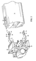
- FIG. 1 is a side view of a fastener-driving tool featuring the present battery/terminal module interface connection, with portions omitted for clarity;
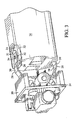
- FIG. 2 is a perspective view of the battery/terminal module assembly showing the components engaged; and
- FIG. 3 is an exploded perspective view of the components of FIG. 2.
-
- Referring now to FIG. 1, a fastener-driving tool suitable for use with the present invention is generally designated 10 and includes a housing 12 (shown in phantom), the operational details of the tool and housing being well known in the art.
- Included in the
housing 12 is a generallytubular cavity 14 configured for receiving at least onebattery 16. Anopening 18 is defined in thecavity 14 through which the battery is inserted. At the opposite end from theopening 18, thecavity 14 has abattery terminal module 20 which electrically connects thebattery 16 to other functional components of the tool, as are known in the art. While only onebattery 16 is depicted, it is contemplated that several batteries may be provided which are connectable in series as is also known in the art. Theterminal module 20 is secured within thecavity 14 by threaded fasteners, chemical adhesives, ultrasonic welding, insert molding or other known fastening technologies. - As described above, one of the operational concerns regarding tools of this type is that the significant vibrational and shock forces generated during combustion, which range from at least about 100g's to in the range of 300-500g's, has been known to cause micro-arcing between corresponding engaged contacts of the
battery 16 and theterminal module 20. Prolonged micro-arcing leads to corrosion of the contacts and in some cases leads to disruption of the battery connection. - Referring now to FIGs. 2 and 3, the
battery 16 has at least onebattery contact element 22 which, in the preferred embodiment includes a generallyplanar contact surface 24 and aterminal engagement edge 26. In the preferred embodiment, there are twosuch contact elements 22, and theterminal engagement edge 26 is radiused to promote and facilitate sliding connection between thebattery 16 and theterminal module 20. It is contemplated that the number and configuration of thebattery contact elements 22 may vary to suit the application. - The
terminal module 20 includes ahousing 24 from which extend at least one and preferably two spring-biased clips 28. Eachclip 28 preferably includes anarched portion 30 and an inclined ordovetailed end portion 31. Thearched portion 30 increases the gripping force of theclip 28 against thebattery contact element 22, and the configuration of theend portion 31 facilitates a smooth transition with the batteryterminal engagement edge 26. In the preferred embodiment, theclips 28 are made of phosphorous/bronze or beryllium/copper alloys, however other spring-like, conductive and durable materials are contemplated. The precise arrangement and configuration of the spring-biased clips 28 may vary to suit the application, as long as the clips generate a biasing force which urges at least one terminalmodule contact element 32, also sometimes referred to as a terminal contact element, against thebattery contact 22. - Between the
arched portion 30 and theend portion 31 is disposed the correspondingmodule contact element 32. While anyshaped contact element 32 is contemplated, it is preferred that the contact element has a hemi-spherical or dome shaped configuration which is radiused or otherwise configured for a smooth contact transition with the correspondingbattery contact element 22. - To prevent corrosion, it is important that both the
battery contact element 22 and the terminalmodule contact element 32 be made of a material which accommodates the above-described micro-arcing as much as possible without reacting with the opposing or interfacing contact element. At the same time, the respective contact elements should be made of a material which is sufficiently conductive to maintain adequate tool performance. - Best results have been obtained when at least one of the battery and terminal
module contact elements - To achieve production-level efficiencies, it is preferred that the
battery contact elements 22 are made of stainless steel and the terminalmodule contact elements 32 are made of precious metal alloy. Silver alloy is particularly preferable due to a combination of oxidative corrosion resistance, conductivity, durability and cost factors. Also, the terminalmodule contact elements 32 are preferably provided in the form of rivets which are frictionally engaged inopenings 34 in acorresponding spring clip 28. While the above-described rivets are preferred, it is anticipated that other types of contact attachment technologies may be employed for attaching thecontact element 32 to the spring clips 28 including, but not limited to crimping, threaded fasteners, inlay technology or the like. It is also contemplated that, depending on the application, thebattery contact elements 22 are made of precious metal alloys and the terminalmodule contact elements 32 are made of stainless steel or combinations of the above, where one of eachcontact elements - It has been found that the combination of stainless steel and precious metal alloy contacts provides the required level of conductivity while retaining anti-oxidation properties desired for preventing the micro-arcing-caused corrosion.
- Each
rivet 32 is provided with a spherical ordomed surface 36 located on aninner surface 38 of thecorresponding spring clip 28 to properly engage thebattery contact element 22 as thebattery 16 is completely inserted into thecavity 14. In this manner, the spherical configuration of theterminal contact element 32 is provided with a smooth transition as it slidingly engages thebattery contact element 22 during battery insertion. Thus, the above-described smooth transition of the interfacingcontact elements terminal engagement end 26, thedovetailed clip end 31 and the domed configuration of therivet 32. - Another feature of the present combination of interfacing contact elements is that the above-described materials provided in the present configuration have been found to withstand, and maintain corrosion-free conductivity while subject to the significant vibration and g forces typically found in combustion powered fastener driving tools. Operational forces in such tools reach at least about 100g's and often achieve or exceed forces in the range of 300-500g's.
Claims (17)
- A fastener driving tool, comprisinga housing (12) defining a cavity (14) for insertion of at least one battery (16);a battery (16) configured for insertion into said cavity and having at least one battery contact element (22);a terminal module (20) disposed in said cavity, constructed and arranged for engaging said battery and making an electrical connection therewith, said module including at least one terminal contact element (32);at least one of said battery and said at least one terminal module contact elements (22, 32) incorporates a precious metal alloy and the other of said contact elements is conductive.
- The tool of claim 1 wherein said precious metal alloy is taken from the group comprised of silver, gold and platinum.
- The tool of claim 2 wherein said precious metal alloy is provided on said at least one terminal module contact element (32).
- The tool of claim 3 wherein said at least one contact element having said precious metal alloy is provided in the form of a rivet (36), and said at least one battery contact element (22) is made of a conductive material.
- The tool of claim 4 wherein said at least one battery contact element (22) is made of stainless steel.
- The tool of claim 1 wherein said at least one battery contact element (22) has a generally planar contact surface (24) and a radiused terminal engagement edge (26).
- The tool of claim 1 wherein said terminal module contact elements (32) are dome-shaped or hemi-spherical, and said battery contact elements (22) have radiused terminal engagement edge (26).
- The tool of claim 1 wherein said at least one terminal module contact element (32) and said at least one battery contact element (22) incorporate precious metal alloy.
- A fastener driving tool, comprising:a housing (12) defining a cavity (14) for insertion of at least one battery (16);a battery (16) configured for insertion into said cavity and having at least one battery contact element (22), said at least one contact element being generally planar (24) and having a radiused terminal engagement end (26); anda terminal module (20) disposed in said cavity, constructed and arranged for engaging said battery and making an electrical connection therewith, said module including at least one spring-biased clip (28) having at least one terminal module contact element (32) being radiused for engagement with said terminal engagement end (26) of said battery contact element (22), said at least one spring biased clip (28) being configured for urging said at least one terminal module contact element (32) against said generally planar surface (24) of said battery contact element (22).
- The tool of claim 9 wherein at least one of said contact elements incorporates a precious metal and the other of said contact elements is conductive.
- The tool of claim 10 wherein said precious metal is provided as a rivet (36) fastened to a spring clip (28) of said at least one terminal module (20).
- The tool of claim 9 wherein said contact elements are configured for conductive engagement upon exposure to at least about 100g's.
- A fastener driving-tool, comprising:a housing (12) defining a cavity (14) for insertion of at least one battery (16);a battery (16) configured for insertion into said cavity and having at least one battery contact element (22);a terminal module (20) disposed in said cavity and constructed and arranged for engaging said battery and making an electrical connection therewith, said module (20) including at least one terminal module contact element (32);said at least one battery contact element (22) and said at least one terminal module contact element (32) being configured for maintaining oxidation-free operation in the range of at least about 100g's.
- The tool of claim 13 wherein at least one of said contact elements (22, 32) incorporates a precious metal and the other of said contact elements is conductive.
- The tool of claim 14 wherein said precious metal contacts are provided in the form of rivets (36), and said battery contact elements (22) are made of stainless steel.
- The tool of claim 13 wherein said at least one battery contact element (22) has a generally planar contact surface (24) and a radiused terminal engagement edge (26).
- The tool of claim 16 wherein said terminal module contact element (32) are dome-shaped or hemi-spherical, and said battery contact elements (22) have a radiused terminal engagement edge (26).
Applications Claiming Priority (2)
| Application Number | Priority Date | Filing Date | Title |
|---|---|---|---|
| US10/155,766 US6786381B2 (en) | 2002-05-24 | 2002-05-24 | Anti-oxidant battery contacts for fastener-driving tool |
| US155766 | 2002-05-24 |
Publications (3)
| Publication Number | Publication Date |
|---|---|
| EP1364751A2 true EP1364751A2 (en) | 2003-11-26 |
| EP1364751A3 EP1364751A3 (en) | 2007-08-29 |
| EP1364751B1 EP1364751B1 (en) | 2013-12-04 |
Family
ID=29400589
Family Applications (1)
| Application Number | Title | Priority Date | Filing Date |
|---|---|---|---|
| EP03291236.2A Expired - Lifetime EP1364751B1 (en) | 2002-05-24 | 2003-05-23 | A fastener driving-tool with anti-oxydant battery contacts |
Country Status (10)
| Country | Link |
|---|---|
| US (1) | US6786381B2 (en) |
| EP (1) | EP1364751B1 (en) |
| JP (2) | JP2004001193A (en) |
| CN (1) | CN100420551C (en) |
| AU (1) | AU2003204260B2 (en) |
| CA (1) | CA2423947C (en) |
| DK (1) | DK1364751T3 (en) |
| MX (1) | MXPA03004559A (en) |
| NZ (1) | NZ526030A (en) |
| TW (1) | TWI284589B (en) |
Cited By (1)
| Publication number | Priority date | Publication date | Assignee | Title |
|---|---|---|---|---|
| EP2193884A1 (en) * | 2007-09-27 | 2010-06-09 | Makita Corporation | Knock-in tool |
Families Citing this family (5)
| Publication number | Priority date | Publication date | Assignee | Title |
|---|---|---|---|---|
| US8591242B2 (en) * | 2010-04-08 | 2013-11-26 | Illinois Tool Works Inc. | Floating battery contact module for a power tool |
| US9889066B2 (en) | 2013-07-01 | 2018-02-13 | Good Fortune 5, Llc | Massaging device having a heat sink |
| CN106374074B (en) * | 2016-11-30 | 2023-05-30 | 桂林智神信息技术股份有限公司 | Battery compartment |
| CN109273629A (en) * | 2018-09-30 | 2019-01-25 | 广州市凯捷电源实业有限公司 | A kind of replaceable terminal battery cover structure |
| TWI749816B (en) * | 2020-10-16 | 2021-12-11 | 朝程工業股份有限公司 | Male and female terminals and adapters for electric tools |
Citations (6)
| Publication number | Priority date | Publication date | Assignee | Title |
|---|---|---|---|---|
| US5028492A (en) * | 1990-03-13 | 1991-07-02 | Olin Corporation | Composite coating for electrical connectors |
| US5598082A (en) * | 1993-11-10 | 1997-01-28 | Intermec Corporation | Replaceable trigger switch for battery operated device |
| US5671815A (en) * | 1995-06-14 | 1997-09-30 | Robert Bosch Gmbh | Hand machine tool with battery operated drive motor |
| US5792573A (en) * | 1994-06-10 | 1998-08-11 | Pitzen; James F. | Rechargeable battery adapted to be attached to orthopedic device |
| US6357534B1 (en) * | 1998-04-20 | 2002-03-19 | Illinois Tool Works Inc | Battery pack latching assembly for fastener driving tool |
| EP1202401A2 (en) * | 2000-10-20 | 2002-05-02 | Tyco Electronics AMP K.K. | Battery connector |
Family Cites Families (19)
| Publication number | Priority date | Publication date | Assignee | Title |
|---|---|---|---|---|
| JPS56121212A (en) * | 1980-02-29 | 1981-09-24 | Matsushita Electric Works Ltd | Contact unit |
| JPS57108207A (en) * | 1980-12-25 | 1982-07-06 | Omron Tateisi Electronics Co | Production of multilayered contacts |
| US4483474A (en) * | 1981-01-22 | 1984-11-20 | Signode Corporation | Combustion gas-powered fastener driving tool |
| JPS58106758A (en) * | 1981-12-17 | 1983-06-25 | Hitachi Koki Co Ltd | Battery terminal device of cordless tool |
| JPS60100182U (en) * | 1983-12-16 | 1985-07-08 | 日立工機株式会社 | rechargeable power tools |
| US4586777A (en) * | 1984-07-16 | 1986-05-06 | Lucerne Products, Inc. | Battery-switch module adapter |
| JPH064532Y2 (en) * | 1988-03-04 | 1994-02-02 | 日立工機株式会社 | Battery connection mechanism |
| JPH0318959A (en) * | 1989-06-15 | 1991-01-28 | Fujitsu Ltd | Memory access system |
| JP2930763B2 (en) * | 1991-02-26 | 1999-08-03 | 日本メクトロン株式会社 | Intermediate board for mounting circuit components and method of manufacturing the same |
| JP2549849Y2 (en) * | 1992-02-26 | 1997-10-08 | リョービ株式会社 | Electrode terminal holder for battery tools |
| US5259769A (en) * | 1992-09-29 | 1993-11-09 | Molex Incorporated | Electrical connector with preloaded spring-like terminal with improved wiping action |
| US5263439A (en) * | 1992-11-13 | 1993-11-23 | Illinois Tool Works Inc. | Fuel system for combustion-powered, fastener-driving tool |
| JPH0763786A (en) * | 1993-06-16 | 1995-03-10 | Nitto Denko Corp | Probe structure |
| US5401592A (en) * | 1993-11-10 | 1995-03-28 | Intermec Corporation | Primary and secondary latching system for securing and protecting a replaceable portable battery pack |
| US5473242A (en) * | 1993-11-10 | 1995-12-05 | Intermec Corporation | Battery contact and method of retention |
| US5472242A (en) * | 1994-06-24 | 1995-12-05 | Petersen; Horst U. | End-fitting for pipe connection having proper insertion indicator |
| FR2774934B1 (en) * | 1998-02-13 | 2000-03-31 | Spit Soc Prospect Inv Techn | COMPRESSED GAS FIXING APPARATUS |
| US6012622A (en) * | 1998-04-20 | 2000-01-11 | Illinois Tool Works Inc. | Fastener driving tool for trim applications |
| JP2002081905A (en) * | 2000-07-04 | 2002-03-22 | Asmo Co Ltd | Rotational position detector and wiper device |
-
2002
- 2002-05-24 US US10/155,766 patent/US6786381B2/en not_active Expired - Lifetime
-
2003
- 2003-03-21 TW TW092106293A patent/TWI284589B/en not_active IP Right Cessation
- 2003-03-26 JP JP2003085140A patent/JP2004001193A/en active Pending
- 2003-03-28 CA CA002423947A patent/CA2423947C/en not_active Expired - Fee Related
- 2003-05-15 CN CNB03131354XA patent/CN100420551C/en not_active Expired - Fee Related
- 2003-05-20 AU AU2003204260A patent/AU2003204260B2/en not_active Ceased
- 2003-05-21 NZ NZ526030A patent/NZ526030A/en not_active IP Right Cessation
- 2003-05-22 MX MXPA03004559A patent/MXPA03004559A/en active IP Right Grant
- 2003-05-23 EP EP03291236.2A patent/EP1364751B1/en not_active Expired - Lifetime
- 2003-05-23 DK DK03291236.2T patent/DK1364751T3/en active
-
2012
- 2012-08-08 JP JP2012176221A patent/JP2012210710A/en active Pending
Patent Citations (6)
| Publication number | Priority date | Publication date | Assignee | Title |
|---|---|---|---|---|
| US5028492A (en) * | 1990-03-13 | 1991-07-02 | Olin Corporation | Composite coating for electrical connectors |
| US5598082A (en) * | 1993-11-10 | 1997-01-28 | Intermec Corporation | Replaceable trigger switch for battery operated device |
| US5792573A (en) * | 1994-06-10 | 1998-08-11 | Pitzen; James F. | Rechargeable battery adapted to be attached to orthopedic device |
| US5671815A (en) * | 1995-06-14 | 1997-09-30 | Robert Bosch Gmbh | Hand machine tool with battery operated drive motor |
| US6357534B1 (en) * | 1998-04-20 | 2002-03-19 | Illinois Tool Works Inc | Battery pack latching assembly for fastener driving tool |
| EP1202401A2 (en) * | 2000-10-20 | 2002-05-02 | Tyco Electronics AMP K.K. | Battery connector |
Non-Patent Citations (1)
| Title |
|---|
| PATENT ABSTRACTS OF JAPAN vol. 007, no. 214 (E-199), 21 September 1983 (1983-09-21) & JP 58 106758 A (HITACHI KOKI KK), 25 June 1983 (1983-06-25) * |
Cited By (3)
| Publication number | Priority date | Publication date | Assignee | Title |
|---|---|---|---|---|
| EP2193884A1 (en) * | 2007-09-27 | 2010-06-09 | Makita Corporation | Knock-in tool |
| EP2193884A4 (en) * | 2007-09-27 | 2011-05-25 | Makita Corp | Knock-in tool |
| US8123098B2 (en) | 2007-09-27 | 2012-02-28 | Makita Corporation | Battery holder for a driving tool |
Also Published As
| Publication number | Publication date |
|---|---|
| US20030218045A1 (en) | 2003-11-27 |
| CN100420551C (en) | 2008-09-24 |
| AU2003204260A1 (en) | 2003-12-11 |
| US6786381B2 (en) | 2004-09-07 |
| TW200306903A (en) | 2003-12-01 |
| EP1364751A3 (en) | 2007-08-29 |
| TWI284589B (en) | 2007-08-01 |
| AU2003204260B2 (en) | 2005-10-20 |
| JP2012210710A (en) | 2012-11-01 |
| DK1364751T3 (en) | 2014-03-03 |
| CN1459362A (en) | 2003-12-03 |
| CA2423947A1 (en) | 2003-11-24 |
| CA2423947C (en) | 2009-11-10 |
| EP1364751B1 (en) | 2013-12-04 |
| JP2004001193A (en) | 2004-01-08 |
| NZ526030A (en) | 2004-06-25 |
| MXPA03004559A (en) | 2003-11-27 |
Similar Documents
| Publication | Publication Date | Title |
|---|---|---|
| EP2116335B1 (en) | Portable tools | |
| JP2012210710A (en) | Fastener-driving tool | |
| US20090186530A1 (en) | Electrical Connector Assembly | |
| EP2193884B1 (en) | Knock-in tool | |
| EP1709723B1 (en) | Integrated brush-holder retention system | |
| EP1234639A3 (en) | Contact trip adjustment for fastening tool | |
| EP1253673A3 (en) | Charge contacts for rechargeable device | |
| EP2556566B1 (en) | Floating battery contact module for a power tool | |
| EP1357640A3 (en) | Electric wire connecting connector | |
| AU2011238763A1 (en) | Floating battery contact module for a power tool | |
| US6671163B2 (en) | Integrated spark and switch unit for combustion fastener driving tool | |
| JP4739910B2 (en) | Battery pack mounting structure for electric tools | |
| GB2436889A (en) | Battery Pack | |
| US20020026859A1 (en) | Plug wrench | |
| WO2014041748A1 (en) | Switch | |
| KR19980061363U (en) | Carbon brush assembly of commutator motor for power tools | |
| EP1707319A3 (en) | Contact trip assembly for fastening tool | |
| JP2008126337A (en) | Battery type portable electric power tool |
Legal Events
| Date | Code | Title | Description |
|---|---|---|---|
| PUAI | Public reference made under article 153(3) epc to a published international application that has entered the european phase |
Free format text: ORIGINAL CODE: 0009012 |
|
| AK | Designated contracting states |
Kind code of ref document: A2 Designated state(s): AT BE BG CH CY CZ DE DK EE ES FI FR GB GR HU IE IT LI LU MC NL PT RO SE SI SK TR |
|
| AX | Request for extension of the european patent |
Extension state: AL LT LV MK |
|
| PUAL | Search report despatched |
Free format text: ORIGINAL CODE: 0009013 |
|
| AK | Designated contracting states |
Kind code of ref document: A3 Designated state(s): AT BE BG CH CY CZ DE DK EE ES FI FR GB GR HU IE IT LI LU MC NL PT RO SE SI SK TR |
|
| AX | Request for extension of the european patent |
Extension state: AL LT LV MK |
|
| 17P | Request for examination filed |
Effective date: 20071018 |
|
| AKX | Designation fees paid |
Designated state(s): AT BE BG CH CY CZ DE DK EE ES FI FR GB GR HU IE IT LI LU MC NL PT RO SE SI SK TR |
|
| 17Q | First examination report despatched |
Effective date: 20090709 |
|
| GRAP | Despatch of communication of intention to grant a patent |
Free format text: ORIGINAL CODE: EPIDOSNIGR1 |
|
| INTG | Intention to grant announced |
Effective date: 20130704 |
|
| GRAS | Grant fee paid |
Free format text: ORIGINAL CODE: EPIDOSNIGR3 |
|
| GRAA | (expected) grant |
Free format text: ORIGINAL CODE: 0009210 |
|
| AK | Designated contracting states |
Kind code of ref document: B1 Designated state(s): AT BE BG CH CY CZ DE DK EE ES FI FR GB GR HU IE IT LI LU MC NL PT RO SE SI SK TR |
|
| REG | Reference to a national code |
Ref country code: GB Ref legal event code: FG4D |
|
| REG | Reference to a national code |
Ref country code: CH Ref legal event code: EP |
|
| REG | Reference to a national code |
Ref country code: AT Ref legal event code: REF Ref document number: 643331 Country of ref document: AT Kind code of ref document: T Effective date: 20140115 Ref country code: IE Ref legal event code: FG4D |
|
| REG | Reference to a national code |
Ref country code: DE Ref legal event code: R096 Ref document number: 60345391 Country of ref document: DE Effective date: 20140123 |
|
| REG | Reference to a national code |
Ref country code: DK Ref legal event code: T3 Effective date: 20140228 |
|
| REG | Reference to a national code |
Ref country code: NL Ref legal event code: T3 |
|
| REG | Reference to a national code |
Ref country code: SE Ref legal event code: TRGR |
|
| REG | Reference to a national code |
Ref country code: AT Ref legal event code: MK05 Ref document number: 643331 Country of ref document: AT Kind code of ref document: T Effective date: 20131204 |
|
| RAP2 | Party data changed (patent owner data changed or rights of a patent transferred) |
Owner name: ILLINOIS TOOL WORKS INC. |
|
| PG25 | Lapsed in a contracting state [announced via postgrant information from national office to epo] |
Ref country code: FI Free format text: LAPSE BECAUSE OF FAILURE TO SUBMIT A TRANSLATION OF THE DESCRIPTION OR TO PAY THE FEE WITHIN THE PRESCRIBED TIME-LIMIT Effective date: 20131204 |
|
| PG25 | Lapsed in a contracting state [announced via postgrant information from national office to epo] |
Ref country code: AT Free format text: LAPSE BECAUSE OF FAILURE TO SUBMIT A TRANSLATION OF THE DESCRIPTION OR TO PAY THE FEE WITHIN THE PRESCRIBED TIME-LIMIT Effective date: 20131204 Ref country code: CY Free format text: LAPSE BECAUSE OF FAILURE TO SUBMIT A TRANSLATION OF THE DESCRIPTION OR TO PAY THE FEE WITHIN THE PRESCRIBED TIME-LIMIT Effective date: 20131204 |
|
| PG25 | Lapsed in a contracting state [announced via postgrant information from national office to epo] |
Ref country code: EE Free format text: LAPSE BECAUSE OF FAILURE TO SUBMIT A TRANSLATION OF THE DESCRIPTION OR TO PAY THE FEE WITHIN THE PRESCRIBED TIME-LIMIT Effective date: 20131204 |
|
| PG25 | Lapsed in a contracting state [announced via postgrant information from national office to epo] |
Ref country code: RO Free format text: LAPSE BECAUSE OF FAILURE TO SUBMIT A TRANSLATION OF THE DESCRIPTION OR TO PAY THE FEE WITHIN THE PRESCRIBED TIME-LIMIT Effective date: 20131204 Ref country code: PT Free format text: LAPSE BECAUSE OF FAILURE TO SUBMIT A TRANSLATION OF THE DESCRIPTION OR TO PAY THE FEE WITHIN THE PRESCRIBED TIME-LIMIT Effective date: 20140404 Ref country code: CZ Free format text: LAPSE BECAUSE OF FAILURE TO SUBMIT A TRANSLATION OF THE DESCRIPTION OR TO PAY THE FEE WITHIN THE PRESCRIBED TIME-LIMIT Effective date: 20131204 Ref country code: ES Free format text: LAPSE BECAUSE OF FAILURE TO SUBMIT A TRANSLATION OF THE DESCRIPTION OR TO PAY THE FEE WITHIN THE PRESCRIBED TIME-LIMIT Effective date: 20131204 Ref country code: SK Free format text: LAPSE BECAUSE OF FAILURE TO SUBMIT A TRANSLATION OF THE DESCRIPTION OR TO PAY THE FEE WITHIN THE PRESCRIBED TIME-LIMIT Effective date: 20131204 |
|
| REG | Reference to a national code |
Ref country code: DE Ref legal event code: R097 Ref document number: 60345391 Country of ref document: DE |
|
| PLBE | No opposition filed within time limit |
Free format text: ORIGINAL CODE: 0009261 |
|
| STAA | Information on the status of an ep patent application or granted ep patent |
Free format text: STATUS: NO OPPOSITION FILED WITHIN TIME LIMIT |
|
| 26N | No opposition filed |
Effective date: 20140905 |
|
| REG | Reference to a national code |
Ref country code: DE Ref legal event code: R097 Ref document number: 60345391 Country of ref document: DE Effective date: 20140905 |
|
| PG25 | Lapsed in a contracting state [announced via postgrant information from national office to epo] |
Ref country code: LU Free format text: LAPSE BECAUSE OF FAILURE TO SUBMIT A TRANSLATION OF THE DESCRIPTION OR TO PAY THE FEE WITHIN THE PRESCRIBED TIME-LIMIT Effective date: 20140523 |
|
| REG | Reference to a national code |
Ref country code: CH Ref legal event code: PL |
|
| PG25 | Lapsed in a contracting state [announced via postgrant information from national office to epo] |
Ref country code: CH Free format text: LAPSE BECAUSE OF NON-PAYMENT OF DUE FEES Effective date: 20140531 Ref country code: LI Free format text: LAPSE BECAUSE OF NON-PAYMENT OF DUE FEES Effective date: 20140531 Ref country code: MC Free format text: LAPSE BECAUSE OF FAILURE TO SUBMIT A TRANSLATION OF THE DESCRIPTION OR TO PAY THE FEE WITHIN THE PRESCRIBED TIME-LIMIT Effective date: 20131204 |
|
| REG | Reference to a national code |
Ref country code: IE Ref legal event code: MM4A |
|
| PG25 | Lapsed in a contracting state [announced via postgrant information from national office to epo] |
Ref country code: SI Free format text: LAPSE BECAUSE OF FAILURE TO SUBMIT A TRANSLATION OF THE DESCRIPTION OR TO PAY THE FEE WITHIN THE PRESCRIBED TIME-LIMIT Effective date: 20131204 |
|
| PG25 | Lapsed in a contracting state [announced via postgrant information from national office to epo] |
Ref country code: IT Free format text: LAPSE BECAUSE OF FAILURE TO SUBMIT A TRANSLATION OF THE DESCRIPTION OR TO PAY THE FEE WITHIN THE PRESCRIBED TIME-LIMIT Effective date: 20131204 Ref country code: IE Free format text: LAPSE BECAUSE OF NON-PAYMENT OF DUE FEES Effective date: 20140523 |
|
| REG | Reference to a national code |
Ref country code: FR Ref legal event code: PLFP Year of fee payment: 14 |
|
| PG25 | Lapsed in a contracting state [announced via postgrant information from national office to epo] |
Ref country code: BG Free format text: LAPSE BECAUSE OF FAILURE TO SUBMIT A TRANSLATION OF THE DESCRIPTION OR TO PAY THE FEE WITHIN THE PRESCRIBED TIME-LIMIT Effective date: 20131204 |
|
| PG25 | Lapsed in a contracting state [announced via postgrant information from national office to epo] |
Ref country code: GR Free format text: LAPSE BECAUSE OF FAILURE TO SUBMIT A TRANSLATION OF THE DESCRIPTION OR TO PAY THE FEE WITHIN THE PRESCRIBED TIME-LIMIT Effective date: 20140305 |
|
| PG25 | Lapsed in a contracting state [announced via postgrant information from national office to epo] |
Ref country code: TR Free format text: LAPSE BECAUSE OF FAILURE TO SUBMIT A TRANSLATION OF THE DESCRIPTION OR TO PAY THE FEE WITHIN THE PRESCRIBED TIME-LIMIT Effective date: 20131204 Ref country code: HU Free format text: LAPSE BECAUSE OF FAILURE TO SUBMIT A TRANSLATION OF THE DESCRIPTION OR TO PAY THE FEE WITHIN THE PRESCRIBED TIME-LIMIT; INVALID AB INITIO Effective date: 20030523 |
|
| REG | Reference to a national code |
Ref country code: FR Ref legal event code: PLFP Year of fee payment: 15 |
|
| REG | Reference to a national code |
Ref country code: FR Ref legal event code: PLFP Year of fee payment: 16 |
|
| PGFP | Annual fee paid to national office [announced via postgrant information from national office to epo] |
Ref country code: NL Payment date: 20220526 Year of fee payment: 20 |
|
| PGFP | Annual fee paid to national office [announced via postgrant information from national office to epo] |
Ref country code: SE Payment date: 20220527 Year of fee payment: 20 Ref country code: GB Payment date: 20220527 Year of fee payment: 20 Ref country code: FR Payment date: 20220525 Year of fee payment: 20 Ref country code: DK Payment date: 20220531 Year of fee payment: 20 Ref country code: DE Payment date: 20220527 Year of fee payment: 20 |
|
| PGFP | Annual fee paid to national office [announced via postgrant information from national office to epo] |
Ref country code: BE Payment date: 20220527 Year of fee payment: 20 |
|
| REG | Reference to a national code |
Ref country code: DE Ref legal event code: R071 Ref document number: 60345391 Country of ref document: DE |
|
| REG | Reference to a national code |
Ref country code: NL Ref legal event code: MK Effective date: 20230522 |
|
| REG | Reference to a national code |
Ref country code: DK Ref legal event code: EUP Expiry date: 20230523 |
|
| REG | Reference to a national code |
Ref country code: BE Ref legal event code: MK Effective date: 20230523 |
|
| REG | Reference to a national code |
Ref country code: GB Ref legal event code: PE20 Expiry date: 20230522 |
|
| REG | Reference to a national code |
Ref country code: SE Ref legal event code: EUG |
|
| PG25 | Lapsed in a contracting state [announced via postgrant information from national office to epo] |
Ref country code: GB Free format text: LAPSE BECAUSE OF EXPIRATION OF PROTECTION Effective date: 20230522 |