EP1367954B1 - intervertebral implant with self-locking fixation - Google Patents
intervertebral implant with self-locking fixation Download PDFInfo
- Publication number
- EP1367954B1 EP1367954B1 EP02722342A EP02722342A EP1367954B1 EP 1367954 B1 EP1367954 B1 EP 1367954B1 EP 02722342 A EP02722342 A EP 02722342A EP 02722342 A EP02722342 A EP 02722342A EP 1367954 B1 EP1367954 B1 EP 1367954B1
- Authority
- EP
- European Patent Office
- Prior art keywords
- tie
- block
- fixing member
- self
- locking fixing
- Prior art date
- Legal status (The legal status is an assumption and is not a legal conclusion. Google has not performed a legal analysis and makes no representation as to the accuracy of the status listed.)
- Expired - Lifetime
Links
- 239000007943 implant Substances 0.000 title claims abstract description 32
- 238000000034 method Methods 0.000 claims description 25
- 230000001154 acute effect Effects 0.000 claims description 3
- 239000000463 material Substances 0.000 claims description 3
- 229920003023 plastic Polymers 0.000 claims description 3
- 239000004033 plastic Substances 0.000 claims description 3
- 210000002445 nipple Anatomy 0.000 description 12
- 230000000903 blocking effect Effects 0.000 description 4
- 210000003041 ligament Anatomy 0.000 description 3
- 238000004140 cleaning Methods 0.000 description 1
- 230000000881 depressing effect Effects 0.000 description 1
- 238000005553 drilling Methods 0.000 description 1
- 238000009434 installation Methods 0.000 description 1
- 238000001356 surgical procedure Methods 0.000 description 1
Images

Classifications
-
- A—HUMAN NECESSITIES
- A61—MEDICAL OR VETERINARY SCIENCE; HYGIENE
- A61F—FILTERS IMPLANTABLE INTO BLOOD VESSELS; PROSTHESES; DEVICES PROVIDING PATENCY TO, OR PREVENTING COLLAPSING OF, TUBULAR STRUCTURES OF THE BODY, e.g. STENTS; ORTHOPAEDIC, NURSING OR CONTRACEPTIVE DEVICES; FOMENTATION; TREATMENT OR PROTECTION OF EYES OR EARS; BANDAGES, DRESSINGS OR ABSORBENT PADS; FIRST-AID KITS
- A61F2/00—Filters implantable into blood vessels; Prostheses, i.e. artificial substitutes or replacements for parts of the body; Appliances for connecting them with the body; Devices providing patency to, or preventing collapsing of, tubular structures of the body, e.g. stents
- A61F2/02—Prostheses implantable into the body
- A61F2/30—Joints
- A61F2/44—Joints for the spine, e.g. vertebrae, spinal discs
-
- A—HUMAN NECESSITIES
- A61—MEDICAL OR VETERINARY SCIENCE; HYGIENE
- A61B—DIAGNOSIS; SURGERY; IDENTIFICATION
- A61B17/00—Surgical instruments, devices or methods, e.g. tourniquets
- A61B17/56—Surgical instruments or methods for treatment of bones or joints; Devices specially adapted therefor
- A61B17/58—Surgical instruments or methods for treatment of bones or joints; Devices specially adapted therefor for osteosynthesis, e.g. bone plates, screws, setting implements or the like
- A61B17/68—Internal fixation devices, including fasteners and spinal fixators, even if a part thereof projects from the skin
- A61B17/70—Spinal positioners or stabilisers ; Bone stabilisers comprising fluid filler in an implant
- A61B17/7062—Devices acting on, attached to, or simulating the effect of, vertebral processes, vertebral facets or ribs ; Tools for such devices
-
- Y—GENERAL TAGGING OF NEW TECHNOLOGICAL DEVELOPMENTS; GENERAL TAGGING OF CROSS-SECTIONAL TECHNOLOGIES SPANNING OVER SEVERAL SECTIONS OF THE IPC; TECHNICAL SUBJECTS COVERED BY FORMER USPC CROSS-REFERENCE ART COLLECTIONS [XRACs] AND DIGESTS
- Y10—TECHNICAL SUBJECTS COVERED BY FORMER USPC
- Y10S—TECHNICAL SUBJECTS COVERED BY FORMER USPC CROSS-REFERENCE ART COLLECTIONS [XRACs] AND DIGESTS
- Y10S606/00—Surgery
- Y10S606/907—Composed of particular material or coated
- Y10S606/91—Polymer
Definitions
- the present invention relates to an intervertebral implant comprising a wedge in which are formed two grooves opposed to each other that the longitudinal axis of said hold crosses and who are likely to receive the two spinous processes of two vertebrae.
- the wedge has two side walls and at least one link fixation for maintaining said spinous processes in said Gorges.
- Intervertebral implants comprising a wedge intended to be inserted between the spinous processes, which prolong the part posterior vertebrae, to limit the approximation are well known.
- the document FR 2,775,183 on which the preamble of claim 1 is based shows such an implant.
- the installation of such implants at the level of the spine requires heavy surgery during which the ligament is removed interspinous connecting the two vertebrae between which we want to interpose the wedge and cleaning recesses in the interspinous space superior and inferior under the interspinous ligaments so as to introduce the links.
- a first end of the link is likely to be connected to said wedge before it is interposed between the spinous processes, for example to at least one of the wings of said throat and then the link is introduced into the interspinous recess so as to surround the apophysis thorny to then be connected to the other wing of the throat.
- the apophysis thorny is maintained by the link in the throat of the hold.
- Only one link is likely to be used to maintain the hold and then it extends to the side wall of the hold to join one of the wings of the opposite throat and then surround the other spinous apophysis for be connected to the other wing of the opposite throat.
- An object of the present invention is to provide an implant intervertebral disc including a wedge and at least one link easy and fast assembly of said implant.
- the present invention has an implant comprising at least one removable self-locking fastener having first connecting means and through which said link is capable of sliding when it is driven in translation according to a first direction, said self-locking fastener being capable of blocking said link in translation according to a second direction opposite to said first direction; and at least one of the two side walls of said wedge comprises second connecting means adapted to cooperate with said first connecting means for connecting said removable self-locking fastener at the side wall of said hold, the drive of said free end of said link so as to cause said link in translation along said first direction producing the tightening of said spinous process in said groove and blockage of said link in translation along said second direction relative to said shim.
- a characteristic of the implant according to the invention reside in the mode of attachment of said link to said hold by means of the removable self-locking fastener which presents first means of connection and which is capable of being connected to said provided hold second means of connection, after the latter has been interposed between the two spinous processes.
- said link whose first end is connected to the hold is introduced in the interspinous recess superior or inferior to the interspinous space in which the wedge is interposed, then the second free end of said link is inserted into said removable self-locking fastener outside of the body of the individual who undergoes the intervention.
- the self-locking fastener removable is then brought to the side of the side wall of the wedge while sliding the link through said piece which is then connected with the hold by the cooperation of the first and second means of link.
- the tightening of the bond which surrounds the spinous process and which the keeps in the throat of the hold is completed after the piece of removable self-locking fastener has been connected to the hold.
- said removable self-locking fastener has a first face main opposite to a second main face that are connected to two ends of said removable self-locking fastener and a central recess forming a slot, opening into said faces principal that said link passes through, so that a first portion of said link between said first end and said central recess is likely to compress a second portion of the said link between said central recess and said second free end of said link against a portion of said first main face joining the first said ends of said self-locking fastener for maintain said link in a fixed position relative to said fastener self-locking.
- the link partially surrounds the removable fastener of way that a first portion is arranged with respect to the first face principal, that the link builds on the second end of the fastener, that it passes through the central recess and that a second portion opening into said first main face is interposed between said first main face and said first link portion, parallel to him.
- said first portion of the link directly extends a part of the link that surrounds the spinous process and which is guided substantially in a plane comprising said first main face in the extension of the first of said ends of said fastening piece, is stretched by the extension in translation of the second free end of said link that extends the second link portion between the first link portion and the first major face.
- the more the link is stretched the more said first portion of the link compresses the second link portion against the first main face and maintains it in a fixed position by providing said self-locking fastener removable.
- said removable self-locking fastener has a central recess forming a slot whose average plane forms an acute angle with said first part of said first main face so as to form a edge in each of the main faces likely to form first friction means for said link.
- the said link is translation into said self-locking fastener, both by the angle that forms the inner wall of the central recess and said first part of the first main face, and the angle formed by the inner wall of the central recess and part of the second main face.
- the second of said ends of said removable self-locking fastener against which said link has two faces inclined relative to each other so as to to form an edge capable of forming second means of friction for said link.
- said second connecting means comprise a housing formed in said wall side of said wedge, the two opposite edges of which are substantially parallel to said axis of the wedge, have means forming an abutment extending substantially perpendicular to said side wall of said shim, and said first connecting means protrude into the side edges of said removable self-locking fastener for abut against said stop means so as to block said self-locking fastener removable in translation relative to said shim, in a direction substantially parallel to said axis longitudinal axis corresponding to said second direction of blocking said link in translation relative to said wedge.
- the removable self-locking fastener is susceptible to be at least partially embedded in a dwelling and to be immobilized in translation along a direction substantially parallel to the longitudinal axis of said shim, particularly according to said second direction corresponding to the tightening of said link on the spinous process.
- the first connecting means projecting into the lateral edges of said fixing piece, they come to bear against the means forming stop when said link is driven for tightening.
- said housing has an open end located opposite said first of said ends of the piece of removable self-locking fastener through which said link is likely to slide.
- the said link is likely to be guided by the walls of said open end when are moving in translation to substantially maintain said link in a plan comprising said first main face so as to compress against she said said second link portion.
- the part of the link arranged of the first main face extends on the one hand towards the apophysis thorny and secondly towards said second of said ends for surround it and apply against the said first main face part after passing through said slot recess; said link forming a loop whose two ends open into said end opened.
- said means forming a stop are constituted by at least two recesses opposite oblongs practiced substantially perpendicular to the said side wall of the shim in the two opposite edges of said housing; and said first connecting means form nipples protruding into the lateral edges of said self-locking fastener, in the extension of one another so as to fit perpendicular to said side wall in said oblong recesses.
- said self-locking fastener is translated in a direction parallel to said second direction and said nipples bear against the edge oblong recesses so as to block said piece.
- said oblong recesses have a portion elastically deformable choke located between an inlet portion and a bottom portion, capable of being deformed by depressing force said nipple so that said nipple is held in a fixed position in said bottom portion.
- said implant comprises two links susceptible to surround an upper spinous process and a spinous process lower, and two removable self-locking fasteners capable of being connected to the two side walls of said hold. So, the apophyses are connected independently of each other to said down.
- said wedge and said removable self-locking fastener are made of plastic material.
- Figure 1 shows an intervertebral implant comprising a shim 10 having an upper groove 12 and a lower groove 14, the two grooves 10 and 12 being opposite each other and traversed by A longitudinal axis A.
- Each of the grooves 12 and 14 are capable of receive a spinous process and the wedge is mounted between the two spinous processes of two vertebrae so as to limit its moving towards each other.
- the implant further comprises two band links, 16 and 18, the first 20 ends of these links are connected, respectively, to each of the two wings 22 and 24 diagonally opposite.
- the link between the first end 20 of a link and the wing 22, 24, is made at by means of a hole 26 passing through the end of the wing, 22, 24 and by the forming a loop sewn from the first end, crossing the drilling.
- the first ends 20 of links 16 and 18 are mounted symmetrical way on the wings 22 and 24, generally, before the intervention surgical.
- a feature of the implant lies in the fashion hooking the second end of the links 28 by means of two removable self-locking fasteners 30, 32 through which the links respectively 18 and 16 are slidable according to directions F and R.
- the links 18 and 16 are blocked in translation in the opposite directions to F and R when in tense position.
- the removable self-locking fasteners 30, 32 in addition to the that they allow the attachment of the links 16, 18 on the hold 10, leave the possibility of being connected to the hold 10 after the latter has been installed in the intervertebral space and that links 16 and 18 were inserted in removable self-locking fasteners 30, 32.
- the removable self-locking fasteners 30, 32 have first connection means 34 forming nipples and making protruding into the side edges of the fasteners 30, 32.
- Figure 1 mainly illustrates one side of the intervertebral implant, the other side, symmetrical with respect to a vertical plane does not appear in Figure 1.
- the nipples 34 have their respective symmetrical edges lateral parts of the fasteners 30, 32.
- the side walls 36 of the shim 10 have second connecting means 38 forming a housing having at least one end 39 open and both of which opposite edges 40 and 42 parallel to each other and to the axis A of the hold 10 have oblong recesses 44 forming stops.
- the width of the housing 38 separating the two opposite edges 40, 42 is greater than the width of the fasteners 30, 32 separating the two opposite side edges so that the fasteners 30, 32 are inserted at least partially into said housing 38.
- the opposite edges 40 and 42 of the housing 38 have two pairs of oblong recesses opposite to cooperate with the pins 34 projecting into the lateral edges of the fasteners 30, 32.
- the distance separating the two oblong recesses from one edge 40 or 42 is substantially equivalent to the distance that separates two pins 34 of a side edge of a fastener 30 or 32.
- the oblong recesses 44 have a constriction 46, deformable, located between the entrance of the oblong recess 44 and the bottom of the recess 44, so that the nipples 34 whose diameter is substantially greater than the width of the constriction 46 can be forced into the oblong recess 44.
- the width the bottom of the oblong recesses corresponds to the diameter of the nipples 44.
- the shim 10 and the fasteners 30, 32 are made of plastic material and have a sufficiently low modulus of elasticity so that both the constriction 46 and the nipple 34 deform elastically and that the nipple is inserted into the bottom of the recess oblong 44.
- the reasoning held for the cooperation of a nipple 34 with an oblong recess 44 is of course likely to be considered all the nipples 34 and all the oblong recesses 44.
- the pieces of removable self-locking fasteners 30 and 32 are recessed in their respective housing 38 in the direction T for the piece 30 and according to the direction P for the piece 32.
- the four pins 34 are situated in the bottom of the four oblong recesses 44, and they can not be removed only by pulling on parts 30 or 32 and on the shim 10 to deform the constriction again 46.
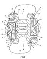
- FIG 2 illustrates the intervertebral implant when both pieces 30 and 32 are embedded in their housing 38.
- FIG 1 we will describe the components of self-locking fasteners block the links 16 and 18 in translation.
- link 18 whose first end 20 is connected to the wing 24, and a part 50 of which is arranged with respect to the groove 14 in which a spinous process, not shown, is likely to come in support. Link 18 then extends to the other wing of the groove 14 to join the self-locking fastening piece 30. As explained in the above description, link 18 is inserted in the fastener 30 prior to its embedding in dwelling 38.
- the self-locking fastener 30 presents a first main face 52 and a second main face 54 opposite to the first, the two opposite faces 52, 54 joining in the first end 56 and in the second end 58 of the fastener 30. It also has a central recess 60 forming a slot debouching in the first main face 52 and in the second face 54.
- the middle plane M of the recess 60 forms an acute angle alpha with the first part of the main face, for example 30 ° of to form a ridge 62.
- the second end 58 of the fastener 30 has two faces inclined with respect to the other, forming a ridge 64.
- the recess 60 opens at the level of the junction between the first main face and the second end 58, thus forming another edge 66.
- the free end 28 of the link 18 for example after being introduced into the lower interspinous space behind the interspinous ligament, is inserted outside the body into the central recess 60 forming a slot from the second main face 54 of the fastener 30.
- the fastener 30 is carried in view of the side wall of the shim 10 by sliding it along the link 18, and arranging it so that the first main face is with regard to the side wall and, that the link part 18 extending the lower interspinous space and the part of link 18 extending through the second free end 28 open into the open end 39 of the fastener 30.
- a link part 18 prolonging the lower interspinous space is applied against the first main face of the fastener 30, then bypasses the second end 58 and applies against a portion of the second face 54 before passing through the central recess 60 forming a slot, for then lead into the first main face 52 and lean against a part of the first main face 52 which joins the first end 56.
- link 18 is illustrated by a line so as not to overload the drawing, but the link 18 has a thickness such that the contact between the two portions 70 and 72 is made possible with the configuration of the fastener 30 and the hold 10.
- link 18 is stretched in the fastener 30 and over, no only the two portions 70 and 72 of link 18 are compressed together, but also the friction means formed by the edges 62 or 66, for example, are effective at blocking the link in translation in a direction opposite to F. In this way, link 18 is maintained immobile in translation relative to the hold 10 and holds the hold 10 on the spinous process.
Abstract
Description
La présente invention concerne un implant intervertébral comprenant une cale dans laquelle sont ménagées deux gorges opposées l'une de l'autre que l'axe longitudinal de ladite cale traverse et qui sont susceptibles de recevoir les deux apophyses épineuses de deux vertèbres. La cale présente deux parois latérales et au moins un lien de fixation pour maintenir lesdites apophyses épineuses dans lesdites gorges.The present invention relates to an intervertebral implant comprising a wedge in which are formed two grooves opposed to each other that the longitudinal axis of said hold crosses and who are likely to receive the two spinous processes of two vertebrae. The wedge has two side walls and at least one link fixation for maintaining said spinous processes in said Gorges.
Des implants intervertébraux comprenant une cale destinée à être insérée entre les apophyses épineuses, qui prolongent la partie postérieure des vertèbres, pour en limiter le rapprochement sont bien connus. Le document FR 2,775,183 sur lequel est basé le préambule de la revendication 1 montre un tel implant. L'installation de tels implants au niveau du rachis nécessite une intervention chirurgicale lourde durant laquelle on désinsère le ligament interépineux reliant les deux vertèbres entre lesquelles on veut interposer la cale et on ménage des évidements dans l'espace interépineux supérieur et inférieur sous les ligaments interépineux de façon à introduire les liens. Une première extrémité du lien est susceptible d'être relié à ladite cale avant qu'elle soit interposée entre les apophyses épineuses, par exemple à au moins une des ailes de ladite gorge, puis le lien est introduit dans l'évidement interépineux de façon à entourer l'apophyse épineuse pour être ensuite relié à l'autre aile de la gorge. Ainsi, l'apophyse épineuse est maintenue par le lien dans la gorge de la cale.Intervertebral implants comprising a wedge intended to be inserted between the spinous processes, which prolong the part posterior vertebrae, to limit the approximation are well known. The document FR 2,775,183 on which the preamble of claim 1 is based shows such an implant. The installation of such implants at the level of the spine requires heavy surgery during which the ligament is removed interspinous connecting the two vertebrae between which we want to interpose the wedge and cleaning recesses in the interspinous space superior and inferior under the interspinous ligaments so as to introduce the links. A first end of the link is likely to be connected to said wedge before it is interposed between the spinous processes, for example to at least one of the wings of said throat and then the link is introduced into the interspinous recess so as to surround the apophysis thorny to then be connected to the other wing of the throat. Thus, the apophysis thorny is maintained by the link in the throat of the hold.
Un seul lien est susceptible d'être utilisé pour maintenir la cale et alors il se prolonge sur la paroi latérale de la cale pour rejoindre l'une des ailes de la gorge opposée puis entourer l'autre apophyse épineuse pour être relié à l'autre aile de la gorge opposée.Only one link is likely to be used to maintain the hold and then it extends to the side wall of the hold to join one of the wings of the opposite throat and then surround the other spinous apophysis for be connected to the other wing of the opposite throat.
Alors que l'interposition de la cale entre les deux apophyses épineuses est relativement aisée et rapide, le rattachement des liens sur la cale est lui, beaucoup plus délicat compte tenu de l'encombrement de l'espace interépineux. Ainsi, la réalisation de boucles et de noeuds est relativement longue et représente une partie non négligeable du temps opératoire.While the interposition of the wedge between the two processes thorny is relatively easy and fast, attaching links to the hold is him, much more delicate given the congestion of interspinous space. So, making loops and knots is relatively long and represents a significant part of the time procedure.
Un objet de la présente invention est de réaliser un implant intervertébral comprenant une cale et au moins un lien qui permettent un montage aisé et rapide dudit implant.An object of the present invention is to provide an implant intervertebral disc including a wedge and at least one link easy and fast assembly of said implant.
Dans ce but, la présente invention présente un implant comprenant, au moins une pièce de fixation auto-bloquante amovible présentant des premiers moyens de liaison et à travers laquelle ledit lien est susceptible de coulisser lorsqu'il est entraíné en translation selon une première direction, ladite pièce de fixation auto-bloquante étant susceptible de bloquer ledit lien en translation selon une seconde direction opposée à ladite première direction ; et au moins une des deux parois latérales de ladite cale comporte des deuxièmes moyens de liaison aptes à coopérer avec lesdits premiers moyens de liaison pour relier ladite pièce de fixation auto-bloquante amovible à la paroi latérale de ladite cale, l'entraínement de ladite extrémité libre dudit lien de façon à entraíner ledit lien en translation selon ladite première direction produisant le serrage de ladite apophyse épineuse dans ladite gorge et le blocage dudit lien en translation selon ladite seconde direction par rapport à ladite cale.For this purpose, the present invention has an implant comprising at least one removable self-locking fastener having first connecting means and through which said link is capable of sliding when it is driven in translation according to a first direction, said self-locking fastener being capable of blocking said link in translation according to a second direction opposite to said first direction; and at least one of the two side walls of said wedge comprises second connecting means adapted to cooperate with said first connecting means for connecting said removable self-locking fastener at the side wall of said hold, the drive of said free end of said link so as to cause said link in translation along said first direction producing the tightening of said spinous process in said groove and blockage of said link in translation along said second direction relative to said shim.
Ainsi, une caractéristique de l'implant conforme à l'invention, réside dans le mode de rattachement dudit lien à ladite cale au moyen de la pièce de fixation auto-bloquante amovible qui présente des premiers moyens de liaison et qui est susceptible d'être reliée à ladite cale munie de deuxièmes moyens de liaison, après que cette dernière a été interposée entre les deux apophyses épineuses. De la sorte, ledit lien dont la première extrémité est reliée à la cale est introduit dans l'évidement interépineux supérieur ou inférieur à l'espace interépineux dans lequel la cale est interposé, puis la seconde extrémité libre dudit lien est inséré dans ladite pièce de fixation auto-bloquante amovible en dehors du corps de l'individu qui subit l'intervention. La pièce de fixation auto-bloquante amovible est alors portée au regard de la paroi latérale de la cale tout en faisant coulisser le lien à travers ladite pièce qui est ensuite reliée à la cale par la coopération des premiers et deuxièmes moyens de liaison. Le serrage du lien qui entoure l'apophyse épineuse et qui la maintient dans la gorge de la cale est achevé après que la pièce de fixation auto-bloquante amovible a été reliée à la cale. Lorsque la seconde extrémité libre du lien est entraínée en translation selon la première direction, la tension du lien dans la pièce de fixation auto-bloquante amovible induit une pression apte à bloquer ledit lien en translation selon une deuxième direction inverse à la première direction.Thus, a characteristic of the implant according to the invention, reside in the mode of attachment of said link to said hold by means of the removable self-locking fastener which presents first means of connection and which is capable of being connected to said provided hold second means of connection, after the latter has been interposed between the two spinous processes. In this way, said link whose first end is connected to the hold is introduced in the interspinous recess superior or inferior to the interspinous space in which the wedge is interposed, then the second free end of said link is inserted into said removable self-locking fastener outside of the body of the individual who undergoes the intervention. The self-locking fastener removable is then brought to the side of the side wall of the wedge while sliding the link through said piece which is then connected with the hold by the cooperation of the first and second means of link. The tightening of the bond which surrounds the spinous process and which the keeps in the throat of the hold is completed after the piece of removable self-locking fastener has been connected to the hold. When the second free end of the link is driven in translation according to the first direction, the tension of the link in the self-locking fastener detachable armature induces a pressure capable of blocking said link in translation according to a second direction opposite to the first direction.
Selon un mode particulier de mise en oeuvre de l'invention, ladite pièce de fixation auto-bloquante amovible présente une première face principale opposée à une seconde face principale qui sont reliées aux deux extrémités de ladite pièce de fixation auto-bloquante amovible et un évidement central formant fente, débouchant dans lesdites faces principales que ledit lien traverse, de façon qu'une première portion dudit lien comprise entre ladite première extrémité et ledit évidement central soit susceptible de comprimer une deuxième portion dudit lien comprise entre ledit évidement central et ladite deuxième extrémité libre dudit lien contre une partie de ladite première face principale rejoignant la première desdites extrémités de ladite pièce de fixation auto-bloquante pour maintenir ledit lien en position fixe par rapport à ladite pièce de fixation auto-bloquante.According to a particular mode of implementation of the invention, said removable self-locking fastener has a first face main opposite to a second main face that are connected to two ends of said removable self-locking fastener and a central recess forming a slot, opening into said faces principal that said link passes through, so that a first portion of said link between said first end and said central recess is likely to compress a second portion of the said link between said central recess and said second free end of said link against a portion of said first main face joining the first said ends of said self-locking fastener for maintain said link in a fixed position relative to said fastener self-locking.
Ainsi, le lien entoure partiellement la pièce de fixation amovible de façon qu'une première portion soit disposée au regard de la première face principale, que le lien prenne appui sur la seconde extrémité de ladite pièce de fixation, qu'il traverse l'évidement central et qu'une deuxième portion débouchant dans ladite première face principale soit interposée entre ladite première face principale et ladite première portion de lien, parallèlement à lui. De la sorte, ladite première portion de lien qui prolonge directement une partie de lien qui entoure l'apophyse épineuse et qui est guidée sensiblement dans un plan comprenant ladite première face principale dans le prolongement de la première desdites extrémités de ladite pièce de fixation, est tendue par l'extension en translation de la seconde extrémité libre dudit lien qui prolonge la seconde portion de lien comprise entre la première portion de lien et la première face principale. Plus le lien est tendu plus ladite première portion de lien comprime la deuxième portion de lien contre la première face principale et la maintient en position fixe par apport à ladite pièce de fixation auto-bloquante amovible.Thus, the link partially surrounds the removable fastener of way that a first portion is arranged with respect to the first face principal, that the link builds on the second end of the fastener, that it passes through the central recess and that a second portion opening into said first main face is interposed between said first main face and said first link portion, parallel to him. In this way, said first portion of the link directly extends a part of the link that surrounds the spinous process and which is guided substantially in a plane comprising said first main face in the extension of the first of said ends of said fastening piece, is stretched by the extension in translation of the second free end of said link that extends the second link portion between the first link portion and the first major face. The more the link is stretched, the more said first portion of the link compresses the second link portion against the first main face and maintains it in a fixed position by providing said self-locking fastener removable.
Selon une caractéristique particulièrement avantageuse, ladite pièce de fixation auto-bloquante amovible présente un évidement central formant fente dont le plan moyen forme un angle aigu avec ladite première partie de ladite première face principale de façon à former une arête dans chacune des faces principales susceptible de former des premiers moyens de frottement pour ledit lien. Ainsi, ledit lien est freiné en translation dans ladite pièce de fixation auto-bloquante, à la fois par l'angle que forme la paroi interne de l'évidement central et ladite première partie de première face principale, et par l'angle que forme la paroi interne de l'évidement central et une partie de la seconde face principale. En outre, de manière avantageuse, la seconde desdites extrémités de ladite pièce de fixation auto-bloquante amovible contre laquelle s'appuie ledit lien, présente deux faces inclinées l'une par rapport à l'autre de façon à former une arête susceptible de former des deuxièmes moyens de frottement pour ledit lien.According to a particularly advantageous characteristic, said removable self-locking fastener has a central recess forming a slot whose average plane forms an acute angle with said first part of said first main face so as to form a edge in each of the main faces likely to form first friction means for said link. Thus, the said link is translation into said self-locking fastener, both by the angle that forms the inner wall of the central recess and said first part of the first main face, and the angle formed by the inner wall of the central recess and part of the second main face. In furthermore, advantageously, the second of said ends of said removable self-locking fastener against which said link, has two faces inclined relative to each other so as to to form an edge capable of forming second means of friction for said link.
Selon un mode de réalisation préférentiel, lesdits deuxièmes moyens de liaison comprennent un logement ménagé dans ladite paroi latérale de ladite cale dont les deux bords opposés, sensiblement parallèles audit axe de la cale, présentent des moyens formant butée s'étendant sensiblement perpendiculairement à ladite paroi latérale de ladite cale, et lesdits premiers moyens de liaison font saillies dans les bords latéraux de ladite pièce de fixation auto-bloquante amovible pour venir en appui contre lesdits moyens formant butée de façon à bloquer ladite pièce de fixation auto-bloquante amovible en translation par rapport à ladite cale, dans une direction sensiblement parallèle audit axe longitudinal correspondant à ladite seconde direction de blocage dudit lien en translation par rapport à ladite cale.According to a preferred embodiment, said second connecting means comprise a housing formed in said wall side of said wedge, the two opposite edges of which are substantially parallel to said axis of the wedge, have means forming an abutment extending substantially perpendicular to said side wall of said shim, and said first connecting means protrude into the side edges of said removable self-locking fastener for abut against said stop means so as to block said self-locking fastener removable in translation relative to said shim, in a direction substantially parallel to said axis longitudinal axis corresponding to said second direction of blocking said link in translation relative to said wedge.
Ainsi, la pièce de fixation auto-bloquante amovible est susceptible d'être encastrée au moins partiellement dans un logement et d'être immobilisée en translation selon une direction sensiblement parallèle à l'axe longitudinal de ladite cale, particulièrement selon ladite seconde direction correspondant au serrage dudit lien sur l'apophyse épineuse. Les premiers moyens de liaison faisant saillie dans les bords latéraux de ladite pièce de fixation, ils viennent en appui contre les moyens formant butée lorsque ledit lien est entraíné pour le serrage.Thus, the removable self-locking fastener is susceptible to be at least partially embedded in a dwelling and to be immobilized in translation along a direction substantially parallel to the longitudinal axis of said shim, particularly according to said second direction corresponding to the tightening of said link on the spinous process. The first connecting means projecting into the lateral edges of said fixing piece, they come to bear against the means forming stop when said link is driven for tightening.
Préférentiellement, ledit logement présente une extrémité ouverte située au regard de ladite première desdites extrémités de la pièce de fixation auto-bloquante amovible à travers laquelle ledit lien est susceptible de coulisser. Ainsi, ledit lien est susceptible d'être guidé par les parois de ladite extrémité ouverte lors de sont déplacement en translation de façon à maintenir sensiblement ledit lien dans un plan comprenant ladite première face principale de façon à comprimer contre elle ladite deuxième portion de lien. La partie de lien disposée au regard de la première face principale se prolonge d'une part vers l'apophyse épineuse et d'autre part vers ladite seconde desdites extrémités pour l'entourer et s'appliquer contre ladite première partie de face principale après passage dans ledit évidement formant fente ; ledit lien formant une boucle dont les deux extrémités débouchent dans ladite extrémité ouverte.Preferably, said housing has an open end located opposite said first of said ends of the piece of removable self-locking fastener through which said link is likely to slide. Thus, the said link is likely to be guided by the walls of said open end when are moving in translation to substantially maintain said link in a plan comprising said first main face so as to compress against she said said second link portion. The part of the link arranged of the first main face extends on the one hand towards the apophysis thorny and secondly towards said second of said ends for surround it and apply against the said first main face part after passing through said slot recess; said link forming a loop whose two ends open into said end opened.
Selon un mode préféré de mise en oeuvre de l'invention, lesdits moyens formant butée sont constitués par au moins deux évidements oblongs en regard pratiqués sensiblement perpendiculairement à ladite paroi latérale de la cale dans les deux bords opposés dudit logement ; et lesdits premiers moyens de liaison forment des tétons faisant saillie dans les bords latéraux de ladite pièce de fixation auto-bloquante, dans le prolongement l'un de l'autre, de façon à s'encastrer perpendiculairement à ladite paroi latérale dans lesdits évidements oblongs. According to a preferred embodiment of the invention, said means forming a stop are constituted by at least two recesses opposite oblongs practiced substantially perpendicular to the said side wall of the shim in the two opposite edges of said housing; and said first connecting means form nipples protruding into the lateral edges of said self-locking fastener, in the extension of one another so as to fit perpendicular to said side wall in said oblong recesses.
De la sorte, lorsque ledit lien est déplacé en translation pour serrer l'apophyse épineuse dans ladite gorge, la pièce de fixation auto-bloquante est entraínée en translation selon une direction parallèle à ladite seconde direction et lesdits tétons viennent en appui contre le bord des évidements oblongs de façon à bloquer ladite pièce. Avantageusement, lesdits évidements oblongs présentent une portion étranglée élastiquement déformable située entre une portion d'entrée et une portion de fond, susceptible de se déformer par enfoncement à force dudit téton de façon que ledit téton soit maintenu en position fixe dans ladite portion de fond. De la sorte, ladite pièce de fixation auto-bloquante amovible est rendue partiellement solidaire de ladite paroi latérale par une simple pression, ce qui facilite le montage.In this way, when said link is moved in translation for tighten the spinous process in said groove, the self-locking fastener is translated in a direction parallel to said second direction and said nipples bear against the edge oblong recesses so as to block said piece. Advantageously, said oblong recesses have a portion elastically deformable choke located between an inlet portion and a bottom portion, capable of being deformed by depressing force said nipple so that said nipple is held in a fixed position in said bottom portion. In this way, said self-locking fastener removable part is partially secured to said side wall by a simple pressure, which facilitates assembly.
Avantageusement, ledit implant comprend deux liens susceptibles d'entourer une apophyse épineuse supérieure et une apophyse épineuse inférieure, et deux pièces de fixation auto-bloquante amovibles susceptibles d'être reliées aux deux parois latérales de ladite cale. Ainsi, les apophyses sont reliées indépendamment les unes des autres à ladite cale.Advantageously, said implant comprises two links susceptible to surround an upper spinous process and a spinous process lower, and two removable self-locking fasteners capable of being connected to the two side walls of said hold. So, the apophyses are connected independently of each other to said down.
Dans un mode de réalisation particulièrement avantageux, ladite cale et ladite pièce de fixation auto-bloquante amovible sont réalisées en matière plastique.In a particularly advantageous embodiment, said wedge and said removable self-locking fastener are made of plastic material.
D'autres particularités et avantages de l'invention ressortiront à la lecture de la description faite ci-après de modes de réalisation particuliers de l'invention, donnés à titre indicatif mais non limitatif, en référence aux dessins annexés sur lesquels :
- la Figure 1 est une vue schématique éclatée de profil montrant l'implant conforme à l'invention ; et,
- la Figure 2, est une vue schématique en coupe verticale de l'invention illustrée sur la Figure 1, l'implant étant monté.
- Figure 1 is an exploded schematic side view showing the implant according to the invention; and,
- Figure 2 is a schematic vertical sectional view of the invention shown in Figure 1, the implant being mounted.
La Figure 1 représente un implant intervertébral comprenant une
cale 10 présentant une gorge supérieure 12 et une gorge inférieure 14,
les deux gorges 10 et 12 étant opposée l'une de l'autre et traversée par
un axe longitudinal A. Chacune des gorges 12 et 14 sont susceptibles de
recevoir une apophyse épineuse et la cale est montée entre les deux
apophyses épineuses de deux vertèbres de façon à en limiter le
déplacement l'une vers l'autre.Figure 1 shows an intervertebral implant comprising a
L'implant comporte en outre, deux liens formant bande, 16 et 18,
les premières extrémités 20 de ces liens sont reliées, respectivement, à
chacune des deux ailes 22 et 24 diagonalement opposées. La liaison
entre la première extrémité 20 d'un lien et l'aile 22, 24, est réalisée au
moyen d'une perçage 26 traversant l'extrémité de l'aile, 22, 24 et par la
formation d'une boucle cousue de la première extrémité, traversant le
perçage. Les premières extrémités 20 des liens 16 et 18 sont montées de
façon symétrique sur les ailes 22 et 24, généralement, avant l'intervention
chirurgicale.The implant further comprises two band links, 16 and 18,
the first 20 ends of these links are connected, respectively, to
each of the two
Par ailleurs, une caractéristique de l'implant réside dans le mode
d'accrochage de la seconde extrémité des liens 28 au moyen de deux
pièces de fixation auto-bloquante amovibles 30, 32 à travers lesquelles les
liens respectivement 18 et 16 sont susceptibles de coulisser selon des
directions F et R. En revanche, comme on l'expliquera plus en détails
dans la suite de la description, les liens 18 et 16 sont bloqués en
translation dans les directions opposées à F et à R lorsqu'ils sont en
position tendue.Moreover, a feature of the implant lies in the fashion
hooking the second end of the
Les pièces de fixation auto-bloquante amovibles 30, 32, outre le
fait qu'elles permettent l'accrochage des liens 16, 18 sur la cale 10,
laissent la possibilité d'être reliées à la cale 10 après que cette dernière a
été installée dans l'espace intervertébrale et que les liens 16 et 18 ont été
insérés dans les pièces de fixation auto-bloquante amovibles 30, 32.The removable self-
A cet effet, les pièces de fixation auto-bloquante amovibles 30, 32
présentent des premiers moyens de liaison 34 formant tétons et faisant
saillie dans les bords latéraux des pièces de fixation 30, 32. La Figure 1
illustre principalement une face de l'implant intervertébral, l'autre face,
symétrique par rapport à un plan vertical n'apparaít pas sur la Figure 1.
Ainsi, les tétons 34 ont respectivement leur symétrique dans les bords
latéraux des pièces de fixation 30, 32. En outre, les parois latérales 36 de
la cale 10 présentent des deuxièmes moyens de liaison 38 formant un
logement dont au moins une extrémité 39 est ouverte et dont les deux
bords opposés 40 et 42 parallèles entre eux et à l'axe A de la cale 10
présentent des évidements oblongs 44 formant butées. Bien entendu, la
largeur du logement 38 séparant les deux bords opposés 40, 42 est
supérieure à la largeur des pièces de fixation 30, 32 séparant les deux
bords latéraux opposés de façon que les pièces de fixation 30, 32 soient
insérées au moins partiellement dans lesdits logements 38.For this purpose, the removable self-
Les bords opposés 40 et 42 du logement 38 présentent deux
paires d'évidements oblongs en regard susceptibles de coopérer avec les
tétons 34 faisant saillie dans les bords latéraux des pièces de fixation 30,
32. Ainsi, la distance qui sépare les deux évidements oblongs d'un bord
40 ou 42 est sensiblement équivalente à la distance qui sépare deux
tétons 34 d'un bord latéral d'une pièce de fixation 30 ou 32.The
En outre, les évidements oblongs 44 présentent un étranglement
46, déformable, situé entre l'entrée de l'évidement oblong 44 et le fond de
l'évidement 44, de façon que les tétons 34 dont le diamètre est
sensiblement supérieur à la largeur de l'étranglement 46 puissent être
enfoncés à force dans l'évidement oblong 44. Bien évidemment, la largeur
du fond des évidements oblongs correspond au diamètre des tétons 44.In addition, the
La cale 10 et les pièces de fixation 30, 32 sont réalisées en
matière plastique et présentent un module d'élasticité suffisamment bas
pour que, à la fois l'étranglement 46 et le téton 34 se déforment
élastiquement et que le téton soit inséré dans le fond de l'évidement
oblong 44. Le raisonnement tenu pour la coopération d'un téton 34 avec
un évidement oblong 44 est bien entendu susceptible d'être tenu pour
tous les tétons 34 et tous les évidements oblongs 44. Ainsi, les pièces de
fixation auto-bloquante amovibles 30 et 32 sont encastrables dans leur
logement respectif 38 selon la direction T pour la pièce 30 et selon la
direction P pour la pièce 32. Lorsque les pièces 30, 32 sont encastrées
dans des parois latérales de ladite cale 10, les quatre tétons 34 sont
situés dans le fond des quatre évidements oblongs 44, et elles ne peuvent
être retirées qu'en exerçant une traction sur les pièces 30 ou 32 et sur la
cale 10 pour déformer à nouveau l'étranglement 46.The
La Figure 2 illustre l'implant intervertébral lorsque les deux pièces
de fixation 30 et 32 sont encastrées dans leur logement 38. En se référant
désormais à cette Figure 2 et également à la Figure 1 on décrira les
éléments constitutifs des pièces de fixation auto-bloquante permettant de
bloquer les liens 16 et 18 en translation.Figure 2 illustrates the intervertebral implant when both
La description qui suit se référera à la pièce de fixation auto-bloquante
amovible 30, mais elle s'applique de manière identique à la
pièce de fixation 32.The following description will refer to the self-locking fastener
removable 30, but it applies identically to the
On retrouve sur la Figure 2, le lien 18 dont la première extrémité
20 est reliée à l'aile 24, et dont une partie 50 est disposée au regard de la
gorge 14 dans laquelle une apophyse épineuse, non représentée, est
susceptible de venir en appui. Le lien 18 se prolonge ensuite vers l'autre
aile de la gorge 14 pour rejoindre la pièce de fixation auto-bloquante 30.
Comme on l'a expliqué dans la description qui précède, le lien 18 est
inséré dans la pièce de fixation 30 préalablement à son encastrement
dans le logement 38.We find in Figure 2, the
La pièce de fixation auto-bloquante 30 présente une première
face principale 52 et une seconde face principale 54 opposée à la
première, les deux faces opposées 52, 54 se rejoignant dans la première
extrémité 56 et dans la seconde extrémité 58 de la pièce de fixation 30.
Elle présente également un évidement central 60 formant fente
débouchant dans la première face principale 52 et dans la seconde face
principale 54. Le plan moyen M de l'évidement 60 forme un angle aigu
alpha avec la première partie de la face principale, par exemple 30° de
façon à former une arête 62 . En outre, la seconde extrémité 58 de la
pièce de fixation 30 présente deux faces inclinées l'une par rapport à
l'autre, formant une arête 64. De plus l'évidement 60 débouche au niveau
de la jonction entre la première face principale et la seconde extrémité 58,
formant ainsi une autre arête 66. The self-locking
Les éléments précédemment décrits permettent de maintenir
immobile en translation le lien 18 par rapport à ladite pièce de fixation 30
et par conséquent par rapport à la cale 10 puisque la pièce de fixation 30
est bloquée dans le logement 38.The previously described elements make it possible to maintain
still in translation the
Pour ce faire, et préalablement à l'encastrement des pièces de
fixation auto-bloquante amovibles dans les parois latérales de la cale 10,
l'extrémité libre 28 du lien 18 par exemple après avoir été introduit dans
l'espace interépineux inférieur derrière le ligament interépineux, est
inséré, en dehors du corps, dans l'évidement central 60 formant fente
depuis la seconde face principale 54 de la pièce de fixation 30. Ensuite, la
pièce de fixation 30 est portée au regard de la paroi latérale de la cale 10
en la faisant coulisser le long du lien 18, et en la disposant de façon que
la première face principale soit au regard de la paroi latérale et, que la
partie de lien 18 prolongeant l'espace interépineux inférieur et la partie de
lien 18 se prolongeant par la seconde extrémité libre 28 débouchent dans
l'extrémité ouverte 39 de la pièce de fixation 30. Ainsi, une partie de lien
18 prolongeant l'espace interépineux inférieur est appliqué contre la
première face principale de la pièce de fixation 30, puis contourne la
seconde extrémité 58 et s'applique contre une portion de la seconde face
principale 54 avant de traverser l'évidement central 60 formant fente, pour
déboucher ensuite dans la première face principale 52 et s'appuyer contre
une partie de la première face principale 52 qui rejoint la première
extrémité 56.To do this, and prior to embedding the pieces of
removable self-locking fasteners in the side walls of the
De la sorte, lorsqu'une traction est exercée sur la seconde
extrémité libre 28 du lien 18 afin de le tendre et de solidariser l'apophyse
épineuse et la cale 10, une première portion 70 de lien 18, comprime une
deuxième portion 72 de lien 18 contre la première face principale et
produit des forces de frottement aptes à immobiliser les portions 70 et 72
de lien 18 les unes par rapport aux autres. Sur la Figure 2, le lien 18 est
illustré par un trait pour ne pas surcharger le dessin, mais le lien 18
présente une épaisseur telle que le contact entre les deux portions 70 et
72 est rendu possible avec la configuration de la pièce de fixation 30 et la
cale 10.In this way, when traction is exerted on the second
Plus le lien 18 est tendu dans la pièce de fixation 30 et plus, non
seulement les deux portions 70 et 72 de lien 18 sont comprimées
ensemble, mais aussi les moyens de frottement formés par les arêtes 62
ou 66, par exemple, sont efficaces pour bloquer le lien en translation
selon une direction opposée à F. De la sorte, le lien 18 est maintenu
immobile en translation par rapport à la cale 10 et maintient la cale 10 sur
l'apophyse épineuse.More the
Bien évidemment, de façon totalement symétrique la cale 10 est
maintenue contre l'autre apophyse épineuse, au moyen du lien 16 et de la
pièce de fixation 32.Of course, in a totally symmetrical way the
Claims (10)
- An intervertebral implant comprising a block (10) with grooves (12, 14) on two opposite sides and on a longitudinal axis (A) of said block (10) adapted to receive the spinous processes of two vertebrae, said block (10) having two lateral walls and at least a fixing tie (16, 18) for retaining said spinous processes in said grooves (12, 14), a first end (20) of said tie (16, 18) being adapted to be connected to said block (10), said tie (16, 18) being adapted to surround at least one spinous process, and the second end (28) of said tie being a free end,
which implant is characterised in that it includes at least a removable self-locking fixing member (30, 32) having first connecting means (34) and through which said tie (16, 18) can slide when it moves in translation in a first direction (R, F), said self-locking fixing member (30, 32) being adapted to immobilize said tie (16, 18) against movement in translation in a second direction opposite said first direction (R, F);
and in that at least one of two lateral walls (36) of said block (10) includes second connecting means (38) adapted to cooperate with said first connecting means (34) to connect said removable self-locking fixing member (30, 32) to the lateral wall (36) of said block (10), movement of said free end (28) of said tie (16, 18) to move said tie (16, 18) in translation in said first direction (R, F) causing said spinous process to be clamped in said groove (12, 14) and said tie (16, 18) to be immobilized against movement in translation relative to said block (10) in said second direction. - An intervertebral implant according to claim 1, characterised in that said removable self-locking fixing member (30, 32) has a first main face (52) opposite a second main face (54), which main faces are joined together at two ends (56, 58) of said removable self-locking fixing member (30, 32) and a central slot (60) opening into said main faces (52, 54) and through which said tie (16, 18) passes, so that a first portion (70) of said tie (16, 18) between said first end (20) and said central slot (60) can press a second portion (72) of said tie between said central opening (60) and said free second end (28) of said tie against a portion of said first main face (52) adjoining the first end (56) of said self-locking fixing member (30, 32) to retain said tie (16, 18) in a fixed position relative to said self-locking fixing member (30, 32).
- An intervertebral implant according to claim 2, characterised in that said removable self-locking fixing member (30, 32) has a central slot (60) whose median plane (M) is at an acute angle (α) to said first portion of said first main face (52) to form an edge (62) in each of the main faces (52, 54) adapted to form first friction means for said tie (16, 18).
- An intervertebral implant according to claim 2 or claim 3, characterised in that the second end (58) of said ends of said removable self-locking fixing member (30, 32) against which said tie (16, 18) bears has two faces inclined to each other to form an edge (64) adapted to form second friction means for said tie.
- An intervertebral implant according to any one of claims 1 to 4,
characterised in that said second connecting means (38) include a housing in said lateral wall (36) of said block (10) whose two opposite edges (40, 42), which are substantially parallel to said axis (A) of the block, include abutment means (44) substantially perpendicular to said lateral wall (36) of said block,
and in that said first connecting means (34) project from lateral sides of said removable self-locking fixing member (30, 32) to bear against said abutment means (44) to immobilize said removable self-locking fixing member (30, 32) against movement in translation relative to said block in a direction substantially parallel to said longitudinal axis (A) and corresponding to said second direction of immobilization of said tie against movement in translation relative to said block (10). - An intervertebral implant according to claim 5, characterised in that said housing has an open end (39) facing said first end (56) of the removable self-locking fixing member (30, 32) and through which said tie (16, 18) can slide.
- An intervertebral implant according to claim 5 or claim 6,
characterised in that said abutment means (44) consist of at least two facing oblong openings substantially perpendicular to said lateral wall (36) of the block in two opposite edges (40, 42) of said housing;
and in that said first connecting means (34) consist of studs projecting from the lateral sides of said self-locking fixing member (30, 32) and aligned with each other, so that they can be inserted into said oblong openings (44) perpendicularly to said lateral wall (36). - An intervertebral implant according to claim 7, characterised in that said oblong openings (44) have an elastically deformable constricted portion (46) between an entry portion and a closed end portion and adapted to be deformed by forcibly pressing in said stud (34) so that said stud (34) is held fixed in position in said closed end portion.
- An intervertebral implant according to any one of claims 1 to 8, characterised in that it includes two ties (16, 18) respectively adapted to surround an upper spinous process and a lower spinous process and two removable self-locking fixing members (30, 32) adapted to be connected to two lateral walls (36) of said block (10).
- An intervertebral implant according to any one of claims 1 to 9, characterised in that said block (10) and said removable self-locking fixing member (30, 32) are made of plastics materials.
Applications Claiming Priority (3)
| Application Number | Priority Date | Filing Date | Title |
|---|---|---|---|
| FR0103362A FR2822051B1 (en) | 2001-03-13 | 2001-03-13 | INTERVERTEBRAL IMPLANT WITH SELF-LOCKING ATTACHMENT |
| FR0103362 | 2001-03-13 | ||
| PCT/FR2002/000888 WO2002071960A1 (en) | 2001-03-13 | 2002-03-13 | Self locking fixable intervertebral implant |
Publications (2)
| Publication Number | Publication Date |
|---|---|
| EP1367954A1 EP1367954A1 (en) | 2003-12-10 |
| EP1367954B1 true EP1367954B1 (en) | 2005-01-05 |
Family
ID=8861029
Family Applications (1)
| Application Number | Title | Priority Date | Filing Date |
|---|---|---|---|
| EP02722342A Expired - Lifetime EP1367954B1 (en) | 2001-03-13 | 2002-03-13 | intervertebral implant with self-locking fixation |
Country Status (13)
| Country | Link |
|---|---|
| US (1) | US7087083B2 (en) |
| EP (1) | EP1367954B1 (en) |
| JP (1) | JP4088529B2 (en) |
| KR (1) | KR100859618B1 (en) |
| AT (1) | ATE286368T1 (en) |
| AU (1) | AU2002253232B2 (en) |
| DE (1) | DE60202518T2 (en) |
| ES (1) | ES2235030T3 (en) |
| FR (1) | FR2822051B1 (en) |
| TW (1) | TW590756B (en) |
| UY (1) | UY27205A1 (en) |
| WO (1) | WO2002071960A1 (en) |
| ZA (1) | ZA200306967B (en) |
Families Citing this family (285)
| Publication number | Priority date | Publication date | Assignee | Title |
|---|---|---|---|---|
| US6068630A (en) | 1997-01-02 | 2000-05-30 | St. Francis Medical Technologies, Inc. | Spine distraction implant |
| US20080086212A1 (en) | 1997-01-02 | 2008-04-10 | St. Francis Medical Technologies, Inc. | Spine distraction implant |
| US7201751B2 (en) | 1997-01-02 | 2007-04-10 | St. Francis Medical Technologies, Inc. | Supplemental spine fixation device |
| US20050245937A1 (en) * | 2004-04-28 | 2005-11-03 | St. Francis Medical Technologies, Inc. | System and method for insertion of an interspinous process implant that is rotatable in order to retain the implant relative to the spinous processes |
| US20080215058A1 (en) | 1997-01-02 | 2008-09-04 | Zucherman James F | Spine distraction implant and method |
| US8128661B2 (en) | 1997-01-02 | 2012-03-06 | Kyphon Sarl | Interspinous process distraction system and method with positionable wing and method |
| US20080027552A1 (en) * | 1997-01-02 | 2008-01-31 | Zucherman James F | Spine distraction implant and method |
| US7959652B2 (en) | 2005-04-18 | 2011-06-14 | Kyphon Sarl | Interspinous process implant having deployable wings and method of implantation |
| US20080071378A1 (en) * | 1997-01-02 | 2008-03-20 | Zucherman James F | Spine distraction implant and method |
| US7306628B2 (en) | 2002-10-29 | 2007-12-11 | St. Francis Medical Technologies | Interspinous process apparatus and method with a selectably expandable spacer |
| US8187303B2 (en) | 2004-04-22 | 2012-05-29 | Gmedelaware 2 Llc | Anti-rotation fixation element for spinal prostheses |
| US6610091B1 (en) | 1999-10-22 | 2003-08-26 | Archus Orthopedics Inc. | Facet arthroplasty devices and methods |
| US7691145B2 (en) | 1999-10-22 | 2010-04-06 | Facet Solutions, Inc. | Prostheses, systems and methods for replacement of natural facet joints with artificial facet joint surfaces |
| US7674293B2 (en) | 2004-04-22 | 2010-03-09 | Facet Solutions, Inc. | Crossbar spinal prosthesis having a modular design and related implantation methods |
| US6579319B2 (en) * | 2000-11-29 | 2003-06-17 | Medicinelodge, Inc. | Facet joint replacement |
| US20050080486A1 (en) | 2000-11-29 | 2005-04-14 | Fallin T. Wade | Facet joint replacement |
| US6419703B1 (en) * | 2001-03-01 | 2002-07-16 | T. Wade Fallin | Prosthesis for the replacement of a posterior element of a vertebra |
| US7090698B2 (en) | 2001-03-02 | 2006-08-15 | Facet Solutions | Method and apparatus for spine joint replacement |
| FR2824261B1 (en) | 2001-05-04 | 2004-05-28 | Ldr Medical | INTERVERTEBRAL DISC PROSTHESIS AND IMPLEMENTATION METHOD AND TOOLS |
| FR2828398B1 (en) * | 2001-08-08 | 2003-09-19 | Jean Taylor | VERTEBRA STABILIZATION ASSEMBLY |
| FR2832917B1 (en) * | 2001-11-30 | 2004-09-24 | Spine Next Sa | ELASTICALLY DEFORMABLE INTERVERTEBRAL IMPLANT |
| US6793678B2 (en) | 2002-06-27 | 2004-09-21 | Depuy Acromed, Inc. | Prosthetic intervertebral motion disc having dampening |
| FR2842724B1 (en) | 2002-07-23 | 2005-05-27 | Spine Next Sa | VERTEBRAL FASTENING SYSTEM |
| FR2844179B1 (en) * | 2002-09-10 | 2004-12-03 | Jean Taylor | POSTERIOR VERTEBRAL SUPPORT KIT |
| US8147548B2 (en) | 2005-03-21 | 2012-04-03 | Kyphon Sarl | Interspinous process implant having a thread-shaped wing and method of implantation |
| US20050075634A1 (en) * | 2002-10-29 | 2005-04-07 | Zucherman James F. | Interspinous process implant with radiolucent spacer and lead-in tissue expander |
| US8070778B2 (en) | 2003-05-22 | 2011-12-06 | Kyphon Sarl | Interspinous process implant with slide-in distraction piece and method of implantation |
| US20080021468A1 (en) | 2002-10-29 | 2008-01-24 | Zucherman James F | Interspinous process implants and methods of use |
| US20060064165A1 (en) * | 2004-09-23 | 2006-03-23 | St. Francis Medical Technologies, Inc. | Interspinous process implant including a binder and method of implantation |
| US7749252B2 (en) * | 2005-03-21 | 2010-07-06 | Kyphon Sarl | Interspinous process implant having deployable wing and method of implantation |
| US8048117B2 (en) | 2003-05-22 | 2011-11-01 | Kyphon Sarl | Interspinous process implant and method of implantation |
| US7549999B2 (en) | 2003-05-22 | 2009-06-23 | Kyphon Sarl | Interspinous process distraction implant and method of implantation |
| US7833246B2 (en) * | 2002-10-29 | 2010-11-16 | Kyphon SÀRL | Interspinous process and sacrum implant and method |
| US7909853B2 (en) | 2004-09-23 | 2011-03-22 | Kyphon Sarl | Interspinous process implant including a binder and method of implantation |
| EP1444960A1 (en) * | 2003-02-07 | 2004-08-11 | DSM IP Assets B.V. | Bone fixing device |
| US7582088B2 (en) | 2003-02-07 | 2009-09-01 | Dsm Ip Assets B.V. | Bone fixing device |
| US7335203B2 (en) | 2003-02-12 | 2008-02-26 | Kyphon Inc. | System and method for immobilizing adjacent spinous processes |
| WO2004084742A1 (en) | 2003-03-24 | 2004-10-07 | Theken Surgical Llc | Spinal implant adjustment device |
| US20040230304A1 (en) | 2003-05-14 | 2004-11-18 | Archus Orthopedics Inc. | Prostheses, tools and methods for replacement of natural facet joints with artifical facet joint surfaces |
| US7608104B2 (en) | 2003-05-14 | 2009-10-27 | Archus Orthopedics, Inc. | Prostheses, tools and methods for replacement of natural facet joints with artifical facet joint surfaces |
| US7074238B2 (en) | 2003-07-08 | 2006-07-11 | Archus Orthopedics, Inc. | Prostheses, tools and methods for replacement of natural facet joints with artificial facet joint surfaces |
| FR2858929B1 (en) * | 2003-08-21 | 2005-09-30 | Spine Next Sa | "INTERVERTEBRAL IMPLANT FOR LOMBO-SACRED JOINT" |
| US7588590B2 (en) | 2003-12-10 | 2009-09-15 | Facet Solutions, Inc | Spinal facet implant with spherical implant apposition surface and bone bed and methods of use |
| US20050131406A1 (en) | 2003-12-15 | 2005-06-16 | Archus Orthopedics, Inc. | Polyaxial adjustment of facet joint prostheses |
| US20080027440A1 (en) * | 2004-01-30 | 2008-01-31 | Dsm Ip Assets B.V. | Fixing Device For Clamping The Ends Of A Surgical Cable Used For Fixing Bone Parts |
| CN101961270B (en) | 2004-02-04 | 2016-08-10 | Ldr医学公司 | Intervertebral disk prosthesis |
| FR2865629B1 (en) | 2004-02-04 | 2007-01-26 | Ldr Medical | INTERVERTEBRAL DISC PROSTHESIS |
| US20050177179A1 (en) * | 2004-02-10 | 2005-08-11 | Baynham Bret O. | Surgical cable system |
| US8562649B2 (en) | 2004-02-17 | 2013-10-22 | Gmedelaware 2 Llc | System and method for multiple level facet joint arthroplasty and fusion |
| US7993373B2 (en) | 2005-02-22 | 2011-08-09 | Hoy Robert W | Polyaxial orthopedic fastening apparatus |
| US8353933B2 (en) | 2007-04-17 | 2013-01-15 | Gmedelaware 2 Llc | Facet joint replacement |
| US8523904B2 (en) | 2004-03-09 | 2013-09-03 | The Board Of Trustees Of The Leland Stanford Junior University | Methods and systems for constraint of spinous processes with attachment |
| US7458981B2 (en) | 2004-03-09 | 2008-12-02 | The Board Of Trustees Of The Leland Stanford Junior University | Spinal implant and method for restricting spinal flexion |
| US7406775B2 (en) | 2004-04-22 | 2008-08-05 | Archus Orthopedics, Inc. | Implantable orthopedic device component selection instrument and methods |
| FR2870107B1 (en) | 2004-05-11 | 2007-07-27 | Spine Next Sa | SELF-LOCKING DEVICE FOR FIXING AN INTERVERTEBRAL IMPLANT |
| FR2870106B1 (en) * | 2004-05-11 | 2007-07-27 | Spine Next Sa | INTERVERTEBRAL IMPLANT |
| EP1746947A4 (en) * | 2004-05-17 | 2010-05-05 | Wooridul Spine Health Inst Co | Spine insert |
| FR2870109B1 (en) * | 2004-05-17 | 2007-04-13 | Spine Next Sa | INTERVERTEBRAL BLADE FOR CERVICAL VERTEBRATES |
| US7585316B2 (en) * | 2004-05-21 | 2009-09-08 | Warsaw Orthopedic, Inc. | Interspinous spacer |
| FR2870719B1 (en) * | 2004-05-27 | 2007-09-21 | Spine Next Sa | SPINAL ARTHROPLASTY SYSTEM |
| US7758581B2 (en) | 2005-03-28 | 2010-07-20 | Facet Solutions, Inc. | Polyaxial reaming apparatus and method |
| US7588578B2 (en) | 2004-06-02 | 2009-09-15 | Facet Solutions, Inc | Surgical measurement systems and methods |
| US8764801B2 (en) | 2005-03-28 | 2014-07-01 | Gmedelaware 2 Llc | Facet joint implant crosslinking apparatus and method |
| US7854752B2 (en) | 2004-08-09 | 2010-12-21 | Theken Spine, Llc | System and method for dynamic skeletal stabilization |
| JP2008510518A (en) | 2004-08-18 | 2008-04-10 | アーカス・オーソペディクス・インコーポレーテッド | Adjoint level articulating device, spinal stabilization system and method |
| US8012209B2 (en) | 2004-09-23 | 2011-09-06 | Kyphon Sarl | Interspinous process implant including a binder, binder aligner and method of implantation |
| US8425559B2 (en) | 2004-10-20 | 2013-04-23 | Vertiflex, Inc. | Systems and methods for posterior dynamic stabilization of the spine |
| US9161783B2 (en) | 2004-10-20 | 2015-10-20 | Vertiflex, Inc. | Interspinous spacer |
| US7763074B2 (en) * | 2004-10-20 | 2010-07-27 | The Board Of Trustees Of The Leland Stanford Junior University | Systems and methods for posterior dynamic stabilization of the spine |
| US8277488B2 (en) | 2004-10-20 | 2012-10-02 | Vertiflex, Inc. | Interspinous spacer |
| US8123807B2 (en) | 2004-10-20 | 2012-02-28 | Vertiflex, Inc. | Systems and methods for posterior dynamic stabilization of the spine |
| US8128662B2 (en) | 2004-10-20 | 2012-03-06 | Vertiflex, Inc. | Minimally invasive tooling for delivery of interspinous spacer |
| US8945183B2 (en) | 2004-10-20 | 2015-02-03 | Vertiflex, Inc. | Interspinous process spacer instrument system with deployment indicator |
| US8273108B2 (en) | 2004-10-20 | 2012-09-25 | Vertiflex, Inc. | Interspinous spacer |
| US8409282B2 (en) | 2004-10-20 | 2013-04-02 | Vertiflex, Inc. | Systems and methods for posterior dynamic stabilization of the spine |
| US8317864B2 (en) | 2004-10-20 | 2012-11-27 | The Board Of Trustees Of The Leland Stanford Junior University | Systems and methods for posterior dynamic stabilization of the spine |
| US9023084B2 (en) | 2004-10-20 | 2015-05-05 | The Board Of Trustees Of The Leland Stanford Junior University | Systems and methods for stabilizing the motion or adjusting the position of the spine |
| US8012207B2 (en) | 2004-10-20 | 2011-09-06 | Vertiflex, Inc. | Systems and methods for posterior dynamic stabilization of the spine |
| US8167944B2 (en) | 2004-10-20 | 2012-05-01 | The Board Of Trustees Of The Leland Stanford Junior University | Systems and methods for posterior dynamic stabilization of the spine |
| US8152837B2 (en) | 2004-10-20 | 2012-04-10 | The Board Of Trustees Of The Leland Stanford Junior University | Systems and methods for posterior dynamic stabilization of the spine |
| US8123782B2 (en) | 2004-10-20 | 2012-02-28 | Vertiflex, Inc. | Interspinous spacer |
| US8613747B2 (en) | 2004-10-20 | 2013-12-24 | Vertiflex, Inc. | Spacer insertion instrument |
| US9119680B2 (en) | 2004-10-20 | 2015-09-01 | Vertiflex, Inc. | Interspinous spacer |
| US9055981B2 (en) | 2004-10-25 | 2015-06-16 | Lanx, Inc. | Spinal implants and methods |
| WO2006047562A2 (en) * | 2004-10-25 | 2006-05-04 | Lins Robert E | Interspinous distraction devices and associated methods of insertion |
| US8241330B2 (en) | 2007-01-11 | 2012-08-14 | Lanx, Inc. | Spinous process implants and associated methods |
| US8221461B2 (en) | 2004-10-25 | 2012-07-17 | Gmedelaware 2 Llc | Crossbar spinal prosthesis having a modular design and systems for treating spinal pathologies |
| ATE524121T1 (en) | 2004-11-24 | 2011-09-15 | Abdou Samy | DEVICES FOR PLACING AN ORTHOPEDIC INTERVERTEBRAL IMPLANT |
| WO2009086010A2 (en) | 2004-12-06 | 2009-07-09 | Vertiflex, Inc. | Spacer insertion instrument |
| FR2879436B1 (en) | 2004-12-22 | 2007-03-09 | Ldr Medical | INTERVERTEBRAL DISC PROSTHESIS |
| US7998208B2 (en) * | 2005-02-17 | 2011-08-16 | Kyphon Sarl | Percutaneous spinal implants and methods |
| US8034080B2 (en) | 2005-02-17 | 2011-10-11 | Kyphon Sarl | Percutaneous spinal implants and methods |
| US20070276372A1 (en) * | 2005-02-17 | 2007-11-29 | Malandain Hugues F | Percutaneous Spinal Implants and Methods |
| US20070276493A1 (en) | 2005-02-17 | 2007-11-29 | Malandain Hugues F | Percutaneous spinal implants and methods |
| US8043335B2 (en) * | 2005-02-17 | 2011-10-25 | Kyphon Sarl | Percutaneous spinal implants and methods |
| US8092459B2 (en) * | 2005-02-17 | 2012-01-10 | Kyphon Sarl | Percutaneous spinal implants and methods |
| US8007521B2 (en) | 2005-02-17 | 2011-08-30 | Kyphon Sarl | Percutaneous spinal implants and methods |
| US8157841B2 (en) | 2005-02-17 | 2012-04-17 | Kyphon Sarl | Percutaneous spinal implants and methods |
| US7998174B2 (en) | 2005-02-17 | 2011-08-16 | Kyphon Sarl | Percutaneous spinal implants and methods |
| US8038698B2 (en) * | 2005-02-17 | 2011-10-18 | Kphon Sarl | Percutaneous spinal implants and methods |
| US8096995B2 (en) | 2005-02-17 | 2012-01-17 | Kyphon Sarl | Percutaneous spinal implants and methods |
| US8097018B2 (en) | 2005-02-17 | 2012-01-17 | Kyphon Sarl | Percutaneous spinal implants and methods |
| US8057513B2 (en) | 2005-02-17 | 2011-11-15 | Kyphon Sarl | Percutaneous spinal implants and methods |
| US7927354B2 (en) | 2005-02-17 | 2011-04-19 | Kyphon Sarl | Percutaneous spinal implants and methods |
| US7993342B2 (en) | 2005-02-17 | 2011-08-09 | Kyphon Sarl | Percutaneous spinal implants and methods |
| US7988709B2 (en) | 2005-02-17 | 2011-08-02 | Kyphon Sarl | Percutaneous spinal implants and methods |
| US20070276373A1 (en) * | 2005-02-17 | 2007-11-29 | Malandain Hugues F | Percutaneous Spinal Implants and Methods |
| US8029567B2 (en) | 2005-02-17 | 2011-10-04 | Kyphon Sarl | Percutaneous spinal implants and methods |
| US8096994B2 (en) | 2005-02-17 | 2012-01-17 | Kyphon Sarl | Percutaneous spinal implants and methods |
| US8100943B2 (en) | 2005-02-17 | 2012-01-24 | Kyphon Sarl | Percutaneous spinal implants and methods |
| US7361196B2 (en) | 2005-02-22 | 2008-04-22 | Stryker Spine | Apparatus and method for dynamic vertebral stabilization |
| JP2006253316A (en) * | 2005-03-09 | 2006-09-21 | Sony Corp | Solid-state image sensing device |
| US7722647B1 (en) | 2005-03-14 | 2010-05-25 | Facet Solutions, Inc. | Apparatus and method for posterior vertebral stabilization |
| US8496686B2 (en) | 2005-03-22 | 2013-07-30 | Gmedelaware 2 Llc | Minimally invasive spine restoration systems, devices, methods and kits |
| US20060241757A1 (en) * | 2005-03-31 | 2006-10-26 | Sdgi Holdings, Inc. | Intervertebral prosthetic device for spinal stabilization and method of manufacturing same |
| US8066742B2 (en) | 2005-03-31 | 2011-11-29 | Warsaw Orthopedic, Inc. | Intervertebral prosthetic device for spinal stabilization and method of implanting same |
| FR2884136B1 (en) * | 2005-04-08 | 2008-02-22 | Spinevision Sa | INTERVERTEBRAL SURGICAL IMPLANT FORMING BALL |
| US7862590B2 (en) * | 2005-04-08 | 2011-01-04 | Warsaw Orthopedic, Inc. | Interspinous process spacer |
| US8034079B2 (en) * | 2005-04-12 | 2011-10-11 | Warsaw Orthopedic, Inc. | Implants and methods for posterior dynamic stabilization of a spinal motion segment |
| US7780709B2 (en) * | 2005-04-12 | 2010-08-24 | Warsaw Orthopedic, Inc. | Implants and methods for inter-transverse process dynamic stabilization of a spinal motion segment |
| US7789898B2 (en) * | 2005-04-15 | 2010-09-07 | Warsaw Orthopedic, Inc. | Transverse process/laminar spacer |
| US7727233B2 (en) * | 2005-04-29 | 2010-06-01 | Warsaw Orthopedic, Inc. | Spinous process stabilization devices and methods |
| US7951199B2 (en) * | 2005-06-15 | 2011-05-31 | Miller Jimmy D | Lateral expandable interbody fusion cage |
| WO2006138690A2 (en) * | 2005-06-17 | 2006-12-28 | Abbott Laboratories | Improved method of treating degenerative spinal disorders |
| US20070005064A1 (en) * | 2005-06-27 | 2007-01-04 | Sdgi Holdings | Intervertebral prosthetic device for spinal stabilization and method of implanting same |
| FR2887434B1 (en) | 2005-06-28 | 2008-03-28 | Jean Taylor | SURGICAL TREATMENT EQUIPMENT OF TWO VERTEBRATES |
| FR2887762B1 (en) | 2005-06-29 | 2007-10-12 | Ldr Medical Soc Par Actions Si | INTERVERTEBRAL DISC PROSTHESIS INSERTION INSTRUMENTATION BETWEEN VERTEBRATES |
| FR2889937B1 (en) * | 2005-08-26 | 2007-11-09 | Abbott Spine Sa | INTERVERTEBRAL IMPLANT FOR LOMBO-SACRED JOINT |
| PL377136A1 (en) | 2005-09-19 | 2007-04-02 | Lfc Spółka Z Ograniczoną Odpowiedzialnością | Intervertebral space implant |
| FR2890850B1 (en) | 2005-09-20 | 2009-04-17 | Abbott Spine Sa | VERTEBRAL FASTENING SYSTEM |
| FR2890851B1 (en) | 2005-09-21 | 2008-06-20 | Abbott Spine Sa | ANCILLARY TO TENSION A FLEXIBLE LINK. |
| US20080183209A1 (en) * | 2005-09-23 | 2008-07-31 | Spinal Kinetics, Inc. | Spinal Stabilization Device |
| FR2891135B1 (en) | 2005-09-23 | 2008-09-12 | Ldr Medical Sarl | INTERVERTEBRAL DISC PROSTHESIS |
| US8267970B2 (en) * | 2005-10-25 | 2012-09-18 | Depuy Spine, Inc. | Laminar hook spring |
| US8357181B2 (en) | 2005-10-27 | 2013-01-22 | Warsaw Orthopedic, Inc. | Intervertebral prosthetic device for spinal stabilization and method of implanting same |
| US8109973B2 (en) | 2005-10-31 | 2012-02-07 | Stryker Spine | Method for dynamic vertebral stabilization |
| US7862591B2 (en) * | 2005-11-10 | 2011-01-04 | Warsaw Orthopedic, Inc. | Intervertebral prosthetic device for spinal stabilization and method of implanting same |
| FR2893838B1 (en) | 2005-11-30 | 2008-08-08 | Ldr Medical Soc Par Actions Si | PROSTHESIS OF INTERVERTEBRAL DISC AND INSTRUMENTATION OF INSERTION OF THE PROSTHESIS BETWEEN VERTEBRATES |
| WO2007075843A2 (en) * | 2005-12-19 | 2007-07-05 | Abdou M S | Devices for inter- vertebral orthopedic device placement |
| WO2007126428A2 (en) | 2005-12-20 | 2007-11-08 | Archus Orthopedics, Inc. | Arthroplasty revision system and method |
| US8083795B2 (en) | 2006-01-18 | 2011-12-27 | Warsaw Orthopedic, Inc. | Intervertebral prosthetic device for spinal stabilization and method of manufacturing same |
| US20070173823A1 (en) * | 2006-01-18 | 2007-07-26 | Sdgi Holdings, Inc. | Intervertebral prosthetic device for spinal stabilization and method of implanting same |
| US7837711B2 (en) * | 2006-01-27 | 2010-11-23 | Warsaw Orthopedic, Inc. | Artificial spinous process for the sacrum and methods of use |
| US7682376B2 (en) | 2006-01-27 | 2010-03-23 | Warsaw Orthopedic, Inc. | Interspinous devices and methods of use |
| US7691130B2 (en) | 2006-01-27 | 2010-04-06 | Warsaw Orthopedic, Inc. | Spinal implants including a sensor and methods of use |
| US20070233068A1 (en) * | 2006-02-22 | 2007-10-04 | Sdgi Holdings, Inc. | Intervertebral prosthetic assembly for spinal stabilization and method of implanting same |
| FR2897771B1 (en) * | 2006-02-28 | 2008-06-06 | Abbott Spine Sa | INTERVERTEBRAL IMPLANT |
| US8262698B2 (en) | 2006-03-16 | 2012-09-11 | Warsaw Orthopedic, Inc. | Expandable device for insertion between anatomical structures and a procedure utilizing same |
| US7985246B2 (en) * | 2006-03-31 | 2011-07-26 | Warsaw Orthopedic, Inc. | Methods and instruments for delivering interspinous process spacers |
| FR2899788B1 (en) * | 2006-04-13 | 2008-07-04 | Jean Taylor | TREATMENT EQUIPMENT FOR VERTEBRATES, COMPRISING AN INTEREPINOUS IMPLANT |
| US8118844B2 (en) | 2006-04-24 | 2012-02-21 | Warsaw Orthopedic, Inc. | Expandable device for insertion between anatomical structures and a procedure utilizing same |
| US8252031B2 (en) | 2006-04-28 | 2012-08-28 | Warsaw Orthopedic, Inc. | Molding device for an expandable interspinous process implant |
| US8105357B2 (en) | 2006-04-28 | 2012-01-31 | Warsaw Orthopedic, Inc. | Interspinous process brace |
| US20070270823A1 (en) | 2006-04-28 | 2007-11-22 | Sdgi Holdings, Inc. | Multi-chamber expandable interspinous process brace |
| US8348978B2 (en) * | 2006-04-28 | 2013-01-08 | Warsaw Orthopedic, Inc. | Interosteotic implant |
| US7846185B2 (en) | 2006-04-28 | 2010-12-07 | Warsaw Orthopedic, Inc. | Expandable interspinous process implant and method of installing same |
| US8048118B2 (en) | 2006-04-28 | 2011-11-01 | Warsaw Orthopedic, Inc. | Adjustable interspinous process brace |
| US8062337B2 (en) | 2006-05-04 | 2011-11-22 | Warsaw Orthopedic, Inc. | Expandable device for insertion between anatomical structures and a procedure utilizing same |
| US20070276496A1 (en) | 2006-05-23 | 2007-11-29 | Sdgi Holdings, Inc. | Surgical spacer with shape control |
| US8147517B2 (en) | 2006-05-23 | 2012-04-03 | Warsaw Orthopedic, Inc. | Systems and methods for adjusting properties of a spinal implant |
| US8048119B2 (en) | 2006-07-20 | 2011-11-01 | Warsaw Orthopedic, Inc. | Apparatus for insertion between anatomical structures and a procedure utilizing same |
| US8702755B2 (en) | 2006-08-11 | 2014-04-22 | Gmedelaware 2 Llc | Angled washer polyaxial connection for dynamic spine prosthesis |
| US20080086115A1 (en) * | 2006-09-07 | 2008-04-10 | Warsaw Orthopedic, Inc. | Intercostal spacer device and method for use in correcting a spinal deformity |
| EP2047813A1 (en) | 2007-10-11 | 2009-04-15 | Abbott Spine | Bone fixing system and method of use |
| US20080082172A1 (en) * | 2006-09-29 | 2008-04-03 | Jackson Roger P | Interspinous process spacer |
| US8066750B2 (en) | 2006-10-06 | 2011-11-29 | Warsaw Orthopedic, Inc | Port structures for non-rigid bone plates |
| US8845726B2 (en) | 2006-10-18 | 2014-09-30 | Vertiflex, Inc. | Dilator |
| US8162982B2 (en) | 2006-10-19 | 2012-04-24 | Simpirica Spine, Inc. | Methods and systems for constraint of multiple spine segments |
| ES2364417T3 (en) * | 2006-10-19 | 2011-09-01 | The Board Of Trustees Of The Leland Stanford Junior University | SYSTEMS FOR THE LIMITATION OF SPINE APOPHYSIS WITH CLAMPS. |
| US8029541B2 (en) | 2006-10-19 | 2011-10-04 | Simpirica Spine, Inc. | Methods and systems for laterally stabilized constraint of spinous processes |
| US20080262549A1 (en) * | 2006-10-19 | 2008-10-23 | Simpirica Spine, Inc. | Methods and systems for deploying spinous process constraints |
| US8187307B2 (en) | 2006-10-19 | 2012-05-29 | Simpirica Spine, Inc. | Structures and methods for constraining spinal processes with single connector |
| US8097019B2 (en) | 2006-10-24 | 2012-01-17 | Kyphon Sarl | Systems and methods for in situ assembly of an interspinous process distraction implant |
| US20080177298A1 (en) * | 2006-10-24 | 2008-07-24 | St. Francis Medical Technologies, Inc. | Tensioner Tool and Method for Implanting an Interspinous Process Implant Including a Binder |
| FR2908035B1 (en) | 2006-11-08 | 2009-05-01 | Jean Taylor | INTEREPINE IMPLANT |
| US20080114357A1 (en) * | 2006-11-15 | 2008-05-15 | Warsaw Orthopedic, Inc. | Inter-transverse process spacer device and method for use in correcting a spinal deformity |
| US7879104B2 (en) | 2006-11-15 | 2011-02-01 | Warsaw Orthopedic, Inc. | Spinal implant system |
| US8105382B2 (en) | 2006-12-07 | 2012-01-31 | Interventional Spine, Inc. | Intervertebral implant |
| DE102006059395A1 (en) * | 2006-12-08 | 2008-06-19 | Aesculap Ag & Co. Kg | Implant and implant system |
| US7955392B2 (en) | 2006-12-14 | 2011-06-07 | Warsaw Orthopedic, Inc. | Interspinous process devices and methods |
| CA2675037A1 (en) | 2007-01-10 | 2008-07-17 | Facet Solutions, Inc. | Taper-locking fixation system |
| US9265532B2 (en) | 2007-01-11 | 2016-02-23 | Lanx, Inc. | Interspinous implants and methods |
| US8465546B2 (en) | 2007-02-16 | 2013-06-18 | Ldr Medical | Intervertebral disc prosthesis insertion assemblies |
| CA2684461C (en) | 2007-04-16 | 2015-06-30 | Vertiflex Inc. | Interspinous spacer |
| US7799058B2 (en) * | 2007-04-19 | 2010-09-21 | Zimmer Gmbh | Interspinous spacer |
| US8840646B2 (en) | 2007-05-10 | 2014-09-23 | Warsaw Orthopedic, Inc. | Spinous process implants and methods |
| US20080281361A1 (en) * | 2007-05-10 | 2008-11-13 | Shannon Marlece Vittur | Posterior stabilization and spinous process systems and methods |
| US20080294200A1 (en) * | 2007-05-25 | 2008-11-27 | Andrew Kohm | Spinous process implants and methods of using the same |
| US8070779B2 (en) * | 2007-06-04 | 2011-12-06 | K2M, Inc. | Percutaneous interspinous process device and method |
| FR2916956B1 (en) | 2007-06-08 | 2012-12-14 | Ldr Medical | INTERSOMATIC CAGE, INTERVERTEBRAL PROSTHESIS, ANCHORING DEVICE AND IMPLANTATION INSTRUMENTATION |
| US20100036424A1 (en) | 2007-06-22 | 2010-02-11 | Simpirica Spine, Inc. | Methods and systems for increasing the bending stiffness and constraining the spreading of a spinal segment |
| EP2182864B1 (en) * | 2007-06-22 | 2016-06-08 | Empirical Spine, Inc. | Devices for controlled flexion restriction of spinal segments |
| US20110172708A1 (en) * | 2007-06-22 | 2011-07-14 | Simpirica Spine, Inc. | Methods and systems for increasing the bending stiffness of a spinal segment with elongation limit |
| US8900307B2 (en) | 2007-06-26 | 2014-12-02 | DePuy Synthes Products, LLC | Highly lordosed fusion cage |
| US8348976B2 (en) * | 2007-08-27 | 2013-01-08 | Kyphon Sarl | Spinous-process implants and methods of using the same |
| FR2921248A1 (en) * | 2007-09-25 | 2009-03-27 | Abbott Spine Sa | DEVICE FOR TIGHTENING TWO PORTIONS OF A BRAID AND INTERVERTEBRAL IMPLANT COMPRISING A BILGE, A BRAID AND A SUCH TIGHTENING DEVICE |
| EP2052689B1 (en) | 2007-10-23 | 2011-12-14 | Zimmer Spine | Fixing devices and stabilization systems using said fixing devices |
| US8128635B2 (en) | 2007-10-23 | 2012-03-06 | Zimmer Spine S.A.S. | Bone fixation tensioning tool and method |
| US20090118833A1 (en) * | 2007-11-05 | 2009-05-07 | Zimmer Spine, Inc. | In-situ curable interspinous process spacer |
| EP2244670B1 (en) | 2008-01-15 | 2017-09-13 | Vertiflex, Inc. | Interspinous spacer |
| EP2471493A1 (en) | 2008-01-17 | 2012-07-04 | Synthes GmbH | An expandable intervertebral implant and associated method of manufacturing the same |
| US20090198338A1 (en) | 2008-02-04 | 2009-08-06 | Phan Christopher U | Medical implants and methods |
| US8252029B2 (en) * | 2008-02-21 | 2012-08-28 | Zimmer Gmbh | Expandable interspinous process spacer with lateral support and method for implantation |
| US8114136B2 (en) | 2008-03-18 | 2012-02-14 | Warsaw Orthopedic, Inc. | Implants and methods for inter-spinous process dynamic stabilization of a spinal motion segment |
| KR20110003475A (en) | 2008-04-05 | 2011-01-12 | 신세스 게엠바하 | Expandable intervertebral implant |
| EP2111810B1 (en) | 2008-04-24 | 2011-07-06 | Zimmer Spine | System for stabilizing at least a portion of the spine |
| CN102036614B (en) | 2008-05-20 | 2013-03-27 | 捷迈脊柱公司 | System for stabilizing at least three vertebrae |
| EP2296567B1 (en) | 2008-06-06 | 2014-03-12 | Simpirica Spine, Inc. | Apparatus for locking a band |
| EP2296566A4 (en) | 2008-06-06 | 2013-01-02 | Simpirica Spine Inc | Methods and apparatus for deploying spinous process constraints |
| US8308771B2 (en) * | 2008-06-06 | 2012-11-13 | Simpirica Spine, Inc. | Methods and apparatus for locking a band |
| US20100012068A1 (en) * | 2008-07-03 | 2010-01-21 | International Engine Intellectual Property Company , Llc | Prioritizing Use Of Engine Cold Start Aids To mitigate Effect Of Weakened Battery Bank |
| JP5687197B2 (en) | 2008-09-03 | 2015-03-18 | シンピライカ スパイン, インコーポレイテッド | Method and apparatus for coupling a prosthesis to a spinal segment |
| US8114131B2 (en) | 2008-11-05 | 2012-02-14 | Kyphon Sarl | Extension limiting devices and methods of use for the spine |
| DE102009004730B4 (en) * | 2009-01-15 | 2017-02-02 | Aesculap Ag | Intervertebral implant and manipulation instrument for this intervertebral implant |
| US8114135B2 (en) | 2009-01-16 | 2012-02-14 | Kyphon Sarl | Adjustable surgical cables and methods for treating spinal stenosis |
| EP2395931A4 (en) | 2009-02-02 | 2013-10-30 | Simpirica Spine Inc | Sacral tether anchor and methods of use |
| WO2010104935A1 (en) | 2009-03-10 | 2010-09-16 | Simpirica Spine, Inc. | Surgical tether apparatus and methods of use |
| US8562653B2 (en) | 2009-03-10 | 2013-10-22 | Simpirica Spine, Inc. | Surgical tether apparatus and methods of use |
| JP5681122B2 (en) | 2009-03-10 | 2015-03-04 | シンピライカ スパイン, インコーポレイテッド | Surgical tether device and method of use |
| WO2010114853A1 (en) | 2009-03-30 | 2010-10-07 | Simpirica Spine, Inc. | Methods and apparatus for improving shear loading capacity of a spinal segment |
| US9526620B2 (en) | 2009-03-30 | 2016-12-27 | DePuy Synthes Products, Inc. | Zero profile spinal fusion cage |
| MX2011010375A (en) | 2009-03-31 | 2012-02-23 | Lanx Inc | Spinous process implants and associated methods. |
| US8372117B2 (en) | 2009-06-05 | 2013-02-12 | Kyphon Sarl | Multi-level interspinous implants and methods of use |
| US8157842B2 (en) | 2009-06-12 | 2012-04-17 | Kyphon Sarl | Interspinous implant and methods of use |
| US20110040332A1 (en) * | 2009-08-11 | 2011-02-17 | Interventional Spine, Inc. | Spinous process spacer and implantation procedure |
| US8771317B2 (en) | 2009-10-28 | 2014-07-08 | Warsaw Orthopedic, Inc. | Interspinous process implant and method of implantation |
| US8795335B1 (en) | 2009-11-06 | 2014-08-05 | Samy Abdou | Spinal fixation devices and methods of use |
| US8764806B2 (en) | 2009-12-07 | 2014-07-01 | Samy Abdou | Devices and methods for minimally invasive spinal stabilization and instrumentation |
| US9393129B2 (en) | 2009-12-10 | 2016-07-19 | DePuy Synthes Products, Inc. | Bellows-like expandable interbody fusion cage |
| US8740948B2 (en) | 2009-12-15 | 2014-06-03 | Vertiflex, Inc. | Spinal spacer for cervical and other vertebra, and associated systems and methods |
| GB0922614D0 (en) | 2009-12-23 | 2010-02-10 | Butterfield Forbes | Device |
| US8114132B2 (en) | 2010-01-13 | 2012-02-14 | Kyphon Sarl | Dynamic interspinous process device |
| US8317831B2 (en) | 2010-01-13 | 2012-11-27 | Kyphon Sarl | Interspinous process spacer diagnostic balloon catheter and methods of use |
| US8262697B2 (en) * | 2010-01-14 | 2012-09-11 | X-Spine Systems, Inc. | Modular interspinous fixation system and method |
| EP2351534B1 (en) * | 2010-02-01 | 2012-08-22 | Zimmer Spine | Intervertebral device |
| US8147526B2 (en) | 2010-02-26 | 2012-04-03 | Kyphon Sarl | Interspinous process spacer diagnostic parallel balloon catheter and methods of use |
| US8979860B2 (en) | 2010-06-24 | 2015-03-17 | DePuy Synthes Products. LLC | Enhanced cage insertion device |
| US9592063B2 (en) | 2010-06-24 | 2017-03-14 | DePuy Synthes Products, Inc. | Universal trial for lateral cages |
| TW201215379A (en) | 2010-06-29 | 2012-04-16 | Synthes Gmbh | Distractible intervertebral implant |
| US8814908B2 (en) | 2010-07-26 | 2014-08-26 | Warsaw Orthopedic, Inc. | Injectable flexible interspinous process device system |
| US8696710B2 (en) | 2010-10-06 | 2014-04-15 | Simpirica Spine, Inc. | Device and accessories for limiting flexion |
| US9402732B2 (en) | 2010-10-11 | 2016-08-02 | DePuy Synthes Products, Inc. | Expandable interspinous process spacer implant |
| US8496689B2 (en) | 2011-02-23 | 2013-07-30 | Farzad Massoudi | Spinal implant device with fusion cage and fixation plates and method of implanting |
| US8562650B2 (en) | 2011-03-01 | 2013-10-22 | Warsaw Orthopedic, Inc. | Percutaneous spinous process fusion plate assembly and method |
| US8425560B2 (en) | 2011-03-09 | 2013-04-23 | Farzad Massoudi | Spinal implant device with fixation plates and lag screws and method of implanting |
| US8591548B2 (en) | 2011-03-31 | 2013-11-26 | Warsaw Orthopedic, Inc. | Spinous process fusion plate assembly |
| US8591549B2 (en) | 2011-04-08 | 2013-11-26 | Warsaw Orthopedic, Inc. | Variable durometer lumbar-sacral implant |
| US20120323276A1 (en) | 2011-06-17 | 2012-12-20 | Bryan Okamoto | Expandable interspinous device |
| US9149306B2 (en) | 2011-06-21 | 2015-10-06 | Seaspine, Inc. | Spinous process device |
| US8845728B1 (en) | 2011-09-23 | 2014-09-30 | Samy Abdou | Spinal fixation devices and methods of use |
| US11812923B2 (en) | 2011-10-07 | 2023-11-14 | Alan Villavicencio | Spinal fixation device |
| KR101121667B1 (en) * | 2012-01-17 | 2012-03-09 | 김창국 | Interspinous spinal spacer |
| US20130226240A1 (en) | 2012-02-22 | 2013-08-29 | Samy Abdou | Spinous process fixation devices and methods of use |
| WO2014018098A1 (en) | 2012-07-26 | 2014-01-30 | DePuy Synthes Products, LLC | Expandable implant |
| US9198767B2 (en) | 2012-08-28 | 2015-12-01 | Samy Abdou | Devices and methods for spinal stabilization and instrumentation |
| US20140067069A1 (en) | 2012-08-30 | 2014-03-06 | Interventional Spine, Inc. | Artificial disc |
| US9320617B2 (en) | 2012-10-22 | 2016-04-26 | Cogent Spine, LLC | Devices and methods for spinal stabilization and instrumentation |
| US9522070B2 (en) | 2013-03-07 | 2016-12-20 | Interventional Spine, Inc. | Intervertebral implant |
| US9510872B2 (en) * | 2013-03-15 | 2016-12-06 | Jcbd, Llc | Spinal stabilization system |
| US9675303B2 (en) | 2013-03-15 | 2017-06-13 | Vertiflex, Inc. | Visualization systems, instruments and methods of using the same in spinal decompression procedures |
| EP2801328A1 (en) | 2013-05-06 | 2014-11-12 | Zimmer Spine | Intervertebral device |
| DE102013016899A1 (en) * | 2013-10-11 | 2015-05-21 | Josef Jansen | Gelenkspacer |
| US10524772B2 (en) | 2014-05-07 | 2020-01-07 | Vertiflex, Inc. | Spinal nerve decompression systems, dilation systems, and methods of using the same |
| AU2015342824B2 (en) | 2014-11-06 | 2020-07-09 | Spinal Elements, Inc. | Apparatus and method of treating spinous processes |
| WO2016137983A1 (en) | 2015-02-24 | 2016-09-01 | X-Spine Systems, Inc. | Modular interspinous fixation system with threaded component |
| US11426290B2 (en) | 2015-03-06 | 2022-08-30 | DePuy Synthes Products, Inc. | Expandable intervertebral implant, system, kit and method |
| US9913727B2 (en) | 2015-07-02 | 2018-03-13 | Medos International Sarl | Expandable implant |
| US10857003B1 (en) | 2015-10-14 | 2020-12-08 | Samy Abdou | Devices and methods for vertebral stabilization |
| EP4233801A3 (en) | 2016-06-28 | 2023-09-06 | Eit Emerging Implant Technologies GmbH | Expandable, angularly adjustable intervertebral cages |
| CN109688980B (en) | 2016-06-28 | 2022-06-10 | Eit 新兴移植技术股份有限公司 | Expandable and angularly adjustable intervertebral cage with articulation joint |
| US10744000B1 (en) | 2016-10-25 | 2020-08-18 | Samy Abdou | Devices and methods for vertebral bone realignment |
| US10973648B1 (en) | 2016-10-25 | 2021-04-13 | Samy Abdou | Devices and methods for vertebral bone realignment |
| US10537436B2 (en) | 2016-11-01 | 2020-01-21 | DePuy Synthes Products, Inc. | Curved expandable cage |
| US10888433B2 (en) | 2016-12-14 | 2021-01-12 | DePuy Synthes Products, Inc. | Intervertebral implant inserter and related methods |
| US10398563B2 (en) | 2017-05-08 | 2019-09-03 | Medos International Sarl | Expandable cage |
| US11344424B2 (en) | 2017-06-14 | 2022-05-31 | Medos International Sarl | Expandable intervertebral implant and related methods |
| US10940016B2 (en) | 2017-07-05 | 2021-03-09 | Medos International Sarl | Expandable intervertebral fusion cage |
| US10456174B2 (en) | 2017-07-31 | 2019-10-29 | Medos International Sarl | Connectors for use in systems and methods for reducing the risk of proximal junctional kyphosis |
| US10463403B2 (en) | 2017-07-31 | 2019-11-05 | Medos International Sarl | Systems and methods for reducing the risk of proximal junctional kyphosis using a bone anchor or other attachment point |
| US11179248B2 (en) | 2018-10-02 | 2021-11-23 | Samy Abdou | Devices and methods for spinal implantation |
| US11446156B2 (en) | 2018-10-25 | 2022-09-20 | Medos International Sarl | Expandable intervertebral implant, inserter instrument, and related methods |
| US11426286B2 (en) | 2020-03-06 | 2022-08-30 | Eit Emerging Implant Technologies Gmbh | Expandable intervertebral implant |
| US11850160B2 (en) | 2021-03-26 | 2023-12-26 | Medos International Sarl | Expandable lordotic intervertebral fusion cage |
| US11752009B2 (en) | 2021-04-06 | 2023-09-12 | Medos International Sarl | Expandable intervertebral fusion cage |
| CN115006115B (en) * | 2022-06-20 | 2023-03-24 | 西安市第一医院 | M shape sticky tape tear device apart |
Family Cites Families (10)
| Publication number | Priority date | Publication date | Assignee | Title |
|---|---|---|---|---|
| US5356412A (en) * | 1992-10-09 | 1994-10-18 | United States Surgical Corporation | Sternum buckle with rotational engagement and method of closure |
| US5496318A (en) * | 1993-01-08 | 1996-03-05 | Advanced Spine Fixation Systems, Inc. | Interspinous segmental spine fixation device |
| FR2704745B1 (en) * | 1993-05-07 | 1995-11-24 | Erpios | Device for connecting the ends of a ligament for osteosynthesis, in particular for vertebral osteosynthesis. |
| FR2717675B1 (en) * | 1994-03-24 | 1996-05-03 | Jean Taylor | Interspinous wedge. |
| FR2722088B1 (en) * | 1994-07-08 | 1998-01-23 | Cahlik Marc Andre | SURGICAL IMPLANT FOR STABILIZING THE INTERVERTEBRAL SPACE |
| US6514256B2 (en) * | 1997-01-02 | 2003-02-04 | St. Francis Medical Technologies, Inc. | Spine distraction implant and method |
| FR2775183B1 (en) * | 1998-02-20 | 2000-08-04 | Jean Taylor | INTER-SPINOUS PROSTHESIS |
| DE29916884U1 (en) * | 1999-09-24 | 2000-11-02 | Link Waldemar Gmbh Co | Surgical cerclage tape |
| EP1502552A3 (en) * | 2000-10-24 | 2005-03-16 | The Spineology Group, LLC | Tension band clip |
| FR2818530B1 (en) * | 2000-12-22 | 2003-10-31 | Spine Next Sa | INTERVERTEBRAL IMPLANT WITH DEFORMABLE SHIM |
-
2001
- 2001-03-13 FR FR0103362A patent/FR2822051B1/en not_active Expired - Fee Related
-
2002
- 2002-03-12 UY UY27205A patent/UY27205A1/en not_active Application Discontinuation
- 2002-03-13 DE DE60202518T patent/DE60202518T2/en not_active Expired - Lifetime
- 2002-03-13 JP JP2002570921A patent/JP4088529B2/en not_active Expired - Lifetime
- 2002-03-13 AT AT02722342T patent/ATE286368T1/en not_active IP Right Cessation
- 2002-03-13 AU AU2002253232A patent/AU2002253232B2/en not_active Ceased
- 2002-03-13 KR KR20037010300A patent/KR100859618B1/en not_active IP Right Cessation
- 2002-03-13 ES ES02722342T patent/ES2235030T3/en not_active Expired - Lifetime
- 2002-03-13 EP EP02722342A patent/EP1367954B1/en not_active Expired - Lifetime
- 2002-03-13 TW TW091104688A patent/TW590756B/en not_active IP Right Cessation
- 2002-03-13 US US10/471,213 patent/US7087083B2/en not_active Expired - Fee Related
- 2002-03-13 WO PCT/FR2002/000888 patent/WO2002071960A1/en active IP Right Grant
-
2003
- 2003-09-05 ZA ZA200306967A patent/ZA200306967B/en unknown
Also Published As
| Publication number | Publication date |
|---|---|
| US20040117017A1 (en) | 2004-06-17 |
| KR100859618B1 (en) | 2008-09-23 |
| JP2004535846A (en) | 2004-12-02 |
| KR20030081423A (en) | 2003-10-17 |
| FR2822051A1 (en) | 2002-09-20 |
| EP1367954A1 (en) | 2003-12-10 |
| ES2235030T3 (en) | 2005-07-01 |
| JP4088529B2 (en) | 2008-05-21 |
| UY27205A1 (en) | 2002-04-26 |
| FR2822051B1 (en) | 2004-02-27 |
| AU2002253232B2 (en) | 2006-06-08 |
| ATE286368T1 (en) | 2005-01-15 |
| US7087083B2 (en) | 2006-08-08 |
| WO2002071960A1 (en) | 2002-09-19 |
| TW590756B (en) | 2004-06-11 |
| DE60202518D1 (en) | 2005-02-10 |
| DE60202518T2 (en) | 2006-05-04 |
| ZA200306967B (en) | 2004-09-06 |
Similar Documents
| Publication | Publication Date | Title |
|---|---|---|
| EP1367954B1 (en) | intervertebral implant with self-locking fixation | |
| EP1448109B1 (en) | Intervertebral implant with elastically deformable wedge | |
| EP2521500B1 (en) | Vertebral attachment device | |
| WO2005120369A1 (en) | Intervertebral implant | |
| EP1746948A1 (en) | Intervertebral wedge for cervical vertebrae | |
| FR2976033A1 (en) | FIXING DEVICES | |
| EP1220644A1 (en) | Intervertebral implant | |
| FR2761256A1 (en) | RACHIDIAN OSTEOSYNTHESIS INSTRUMENTATION WITH CONNECTING CONNECTOR BETWEEN A VERTEBRAL ROD AND BONE ANCHORING ORGANS | |
| EP1924210A2 (en) | Intervertebral implant for the lumbosacral joint | |
| CH694357A5 (en) | The fastener assembly of a soft tissue to bone | |
| FR2977138A1 (en) | DEVICE FOR FIXING VERTEBRAL | |
| WO2003026521A1 (en) | Vertebral fixing device | |
| FR3000771A1 (en) | CLAMP FOR ATTACHING A PANEL TO A SUPPORT AND ASSEMBLY OBTAINED | |
| FR2513328A1 (en) | TIGHTENING NECK | |
| CA2971001C (en) | Device for attaching a flat band on a bone part | |
| WO2009071772A1 (en) | Improved junction device for conveyor belts | |
| FR3008456A1 (en) | ATTACHMENT CLUSTER FOR TUBULAR HEATING FLOOR DRIVING | |
| FR2784729A1 (en) | Folding clip for anchorage of rope end forming a loop | |
| EP0457696B1 (en) | System for joining the traction cables with the traction levers of negative dobbies | |
| WO1988006011A1 (en) | Blocking device for flexible ties | |
| EP3082630A1 (en) | Vertebral fixation device with double fastening, system and method for blocking a loop with such a device | |
| WO2009133250A1 (en) | Anchor clamp for telecommunications cable | |
| FR3055888A1 (en) | FIXING FOR SURFACE LINK | |
| FR2956567A1 (en) | Loop type device for flexible cord i.e. tightening lace, of shoe by children, has fixed and movable elements comprising complementary units for ensuring removable locking of movable element in active position | |
| FR2732728A1 (en) | Mutual fixing of two ends of tie for strapping packets or boxes |
Legal Events
| Date | Code | Title | Description |
|---|---|---|---|
| PUAI | Public reference made under article 153(3) epc to a published international application that has entered the european phase |
Free format text: ORIGINAL CODE: 0009012 |
|
| 17P | Request for examination filed |
Effective date: 20030812 |
|
| AK | Designated contracting states |
Kind code of ref document: A1 Designated state(s): AT BE CH CY DE DK ES FI FR GB GR IE IT LI LU MC NL PT SE TR |
|
| AX | Request for extension of the european patent |
Extension state: AL LT LV MK RO SI |
|
| GRAP | Despatch of communication of intention to grant a patent |
Free format text: ORIGINAL CODE: EPIDOSNIGR1 |
|
| RTI1 | Title (correction) |
Free format text: INTERVERTEBRAL IMPLANT WITH SELF-LOCKING FIXATION |
|
| GRAS | Grant fee paid |
Free format text: ORIGINAL CODE: EPIDOSNIGR3 |
|
| GRAA | (expected) grant |
Free format text: ORIGINAL CODE: 0009210 |
|
| AK | Designated contracting states |
Kind code of ref document: B1 Designated state(s): AT BE CH CY DE DK ES FI FR GB GR IE IT LI LU MC NL PT SE TR |
|
| PG25 | Lapsed in a contracting state [announced via postgrant information from national office to epo] |
Ref country code: IE Free format text: LAPSE BECAUSE OF FAILURE TO SUBMIT A TRANSLATION OF THE DESCRIPTION OR TO PAY THE FEE WITHIN THE PRESCRIBED TIME-LIMIT Effective date: 20050105 Ref country code: TR Free format text: LAPSE BECAUSE OF FAILURE TO SUBMIT A TRANSLATION OF THE DESCRIPTION OR TO PAY THE FEE WITHIN THE PRESCRIBED TIME-LIMIT Effective date: 20050105 Ref country code: FI Free format text: LAPSE BECAUSE OF FAILURE TO SUBMIT A TRANSLATION OF THE DESCRIPTION OR TO PAY THE FEE WITHIN THE PRESCRIBED TIME-LIMIT Effective date: 20050105 Ref country code: NL Free format text: LAPSE BECAUSE OF FAILURE TO SUBMIT A TRANSLATION OF THE DESCRIPTION OR TO PAY THE FEE WITHIN THE PRESCRIBED TIME-LIMIT Effective date: 20050105 Ref country code: AT Free format text: LAPSE BECAUSE OF FAILURE TO SUBMIT A TRANSLATION OF THE DESCRIPTION OR TO PAY THE FEE WITHIN THE PRESCRIBED TIME-LIMIT Effective date: 20050105 |
|
| REG | Reference to a national code |
Ref country code: GB Ref legal event code: FG4D Free format text: NOT ENGLISH |
|
| REG | Reference to a national code |
Ref country code: CH Ref legal event code: EP |
|
| REG | Reference to a national code |
Ref country code: IE Ref legal event code: FG4D Free format text: FRENCH |
|
| REF | Corresponds to: |
Ref document number: 60202518 Country of ref document: DE Date of ref document: 20050210 Kind code of ref document: P |
|
| PG25 | Lapsed in a contracting state [announced via postgrant information from national office to epo] |
Ref country code: CY Free format text: LAPSE BECAUSE OF FAILURE TO SUBMIT A TRANSLATION OF THE DESCRIPTION OR TO PAY THE FEE WITHIN THE PRESCRIBED TIME-LIMIT Effective date: 20050313 Ref country code: LU Free format text: LAPSE BECAUSE OF NON-PAYMENT OF DUE FEES Effective date: 20050313 |
|
| PG25 | Lapsed in a contracting state [announced via postgrant information from national office to epo] |
Ref country code: MC Free format text: LAPSE BECAUSE OF NON-PAYMENT OF DUE FEES Effective date: 20050331 Ref country code: BE Free format text: LAPSE BECAUSE OF NON-PAYMENT OF DUE FEES Effective date: 20050331 |
|
| PG25 | Lapsed in a contracting state [announced via postgrant information from national office to epo] |
Ref country code: SE Free format text: LAPSE BECAUSE OF FAILURE TO SUBMIT A TRANSLATION OF THE DESCRIPTION OR TO PAY THE FEE WITHIN THE PRESCRIBED TIME-LIMIT Effective date: 20050405 Ref country code: GR Free format text: LAPSE BECAUSE OF FAILURE TO SUBMIT A TRANSLATION OF THE DESCRIPTION OR TO PAY THE FEE WITHIN THE PRESCRIBED TIME-LIMIT Effective date: 20050405 Ref country code: DK Free format text: LAPSE BECAUSE OF FAILURE TO SUBMIT A TRANSLATION OF THE DESCRIPTION OR TO PAY THE FEE WITHIN THE PRESCRIBED TIME-LIMIT Effective date: 20050405 |
|
| GBT | Gb: translation of ep patent filed (gb section 77(6)(a)/1977) |
Effective date: 20050415 |
|
| NLV1 | Nl: lapsed or annulled due to failure to fulfill the requirements of art. 29p and 29m of the patents act | ||
| REG | Reference to a national code |
Ref country code: ES Ref legal event code: FG2A Ref document number: 2235030 Country of ref document: ES Kind code of ref document: T3 |
|
| REG | Reference to a national code |
Ref country code: IE Ref legal event code: FD4D |
|
| BERE | Be: lapsed |
Owner name: SPINE NEXT Effective date: 20050331 |
|
| PLBE | No opposition filed within time limit |
Free format text: ORIGINAL CODE: 0009261 |
|
| STAA | Information on the status of an ep patent application or granted ep patent |
Free format text: STATUS: NO OPPOSITION FILED WITHIN TIME LIMIT |
|
| 26N | No opposition filed |
Effective date: 20051006 |
|
| REG | Reference to a national code |
Ref country code: GB Ref legal event code: FG4D Free format text: NOT ENGLISH |
|
| PG25 | Lapsed in a contracting state [announced via postgrant information from national office to epo] |
Ref country code: LI Free format text: LAPSE BECAUSE OF NON-PAYMENT OF DUE FEES Effective date: 20060331 Ref country code: CH Free format text: LAPSE BECAUSE OF NON-PAYMENT OF DUE FEES Effective date: 20060331 |
|
| REG | Reference to a national code |
Ref country code: FR Ref legal event code: CD |
|
| REG | Reference to a national code |
Ref country code: CH Ref legal event code: PL |
|
| BERE | Be: lapsed |
Owner name: SPINE NEXT Effective date: 20050331 |
|
| PG25 | Lapsed in a contracting state [announced via postgrant information from national office to epo] |
Ref country code: PT Free format text: LAPSE BECAUSE OF NON-PAYMENT OF DUE FEES Effective date: 20050605 |
|
| REG | Reference to a national code |
Ref country code: FR Ref legal event code: CD Ref country code: FR Ref legal event code: CJ |
|
| PGFP | Annual fee paid to national office [announced via postgrant information from national office to epo] |
Ref country code: IT Payment date: 20120316 Year of fee payment: 11 |
|
| PGFP | Annual fee paid to national office [announced via postgrant information from national office to epo] |
Ref country code: ES Payment date: 20120320 Year of fee payment: 11 |
|
| PG25 | Lapsed in a contracting state [announced via postgrant information from national office to epo] |
Ref country code: IT Free format text: LAPSE BECAUSE OF NON-PAYMENT OF DUE FEES Effective date: 20130313 |
|
| REG | Reference to a national code |
Ref country code: ES Ref legal event code: FD2A Effective date: 20140612 |
|
| PG25 | Lapsed in a contracting state [announced via postgrant information from national office to epo] |
Ref country code: ES Free format text: LAPSE BECAUSE OF NON-PAYMENT OF DUE FEES Effective date: 20130314 |
|
| REG | Reference to a national code |
Ref country code: FR Ref legal event code: PLFP Year of fee payment: 15 |
|
| REG | Reference to a national code |
Ref country code: FR Ref legal event code: PLFP Year of fee payment: 16 |
|
| PGFP | Annual fee paid to national office [announced via postgrant information from national office to epo] |
Ref country code: FR Payment date: 20170213 Year of fee payment: 16 Ref country code: DE Payment date: 20170307 Year of fee payment: 16 |
|
| PGFP | Annual fee paid to national office [announced via postgrant information from national office to epo] |
Ref country code: GB Payment date: 20170308 Year of fee payment: 16 |
|
| REG | Reference to a national code |
Ref country code: DE Ref legal event code: R119 Ref document number: 60202518 Country of ref document: DE |
|
| GBPC | Gb: european patent ceased through non-payment of renewal fee |
Effective date: 20180313 |
|
| PG25 | Lapsed in a contracting state [announced via postgrant information from national office to epo] |
Ref country code: DE Free format text: LAPSE BECAUSE OF NON-PAYMENT OF DUE FEES Effective date: 20181002 |
|
| PG25 | Lapsed in a contracting state [announced via postgrant information from national office to epo] |
Ref country code: GB Free format text: LAPSE BECAUSE OF NON-PAYMENT OF DUE FEES Effective date: 20180313 |
|
| PG25 | Lapsed in a contracting state [announced via postgrant information from national office to epo] |
Ref country code: FR Free format text: LAPSE BECAUSE OF NON-PAYMENT OF DUE FEES Effective date: 20180331 |