The present invention is concerned with digital
image processing and, more particularly, regards a
motion estimation method and a stabilization method for
an image sequence.
Digital images are nowadays used in many different
applications, a case in point being such traditional
acquisition devices as digital still and video cameras.
One must also expect an ever greater use of digital
images in devices of the new generation, for example, in
mobile multimedia communication terminals.
There exist numerous devices or applications that
use digital images acquired in sequence, i.e. images
acquired with a brief time interval between one image
and the next and representing approximately one and the
same real scene.
The acquisition rate of the sequence, i.e. the
number of images acquired in a given time interval, may
vary in accordance with the specific applications; for
example, the rate will be very high in digital video
cameras (about 25 images per second) and lower in mobile
communication terminals (about 15 images per second)
that acquire the digital images and transmit them in
real time to a remote terminal.
The number of digital images comprised in the
sequence can likewise vary within wide limits: for
example, the sequence may contain a large number of
images (video sequence), but there are also many known
specific applications of digital photography for which
it is sufficient to acquire sequences containing just a
few images (two or three, for example).
It is known that the image sequences are often
affected by unwanted displacements/motions between
images produced in the acquisition phase. Such unwanted
motions may be due to, for example, vibrations,
fluctuations or micro-oscillations of the acquisition
device during the acquisition of the sequence.
There are several known compensation or correction
techniques intended to reduce or eliminate these
unwanted motions. For example, in digital image
processing - and especially in digital photography
applications - there are known various techniques that
are generally referred to as alignment/registration
techniques. When this term is used hereinafter, it is
intended to refer particularly to the correction of
unwanted motion in sequences that comprise few images
(photography or still camera applications).
When digital sequences are acquired for generic
video applications, on the other hand, the techniques
for compensating these unwanted motions are commonly
known by the name of stabilization techniques. When this
term is used hereinafter, it is intended to refer
particularly to the correction of unwanted motion in
sequences that comprise a large number of images (video
applications).
In particular, the stabilization of video sequences
plays an important part, because - as is well known to
persons skilled in the art - it not only eliminates
unpleasant oscillations and vibrations that would be
visible in the reproduction of these sequences (a film,
for example), but also makes it possible to obtain a
greater compression efficiency when the sequences are
encoded by means of encoding /compression techniques
that operate, for example, in accordance with the MPEG
standard or the H263 standard and are nowadays
extensively used in the greater part of the available
commercial devices.
Conventionally, both the alignment/registration
techniques and the stabilization techniques correct the
acquired sequence after a phase of estimating the
relative motions between image pairs of the sequence.
This phase, which will hereinafter be referred to as the
motion estimation (or Mot Est) phase, produces an
estimate of the motion of the sequence by evaluating,
for example, the motion of each image of the sequence
with respect to a reference image.
In particular, techniques of motion estimation
between a first and a second image that use a motion
model on the basis of which the second image corresponds
substantially to a rigid rotation/translation of the
first image are known by the name of "global motion"
techniques. Commonly, the motion model is further
simplified and in actual fact the global motion
estimation produces an estimation of the relative
motion/ misalignment between a pair of images in the
form of a global motion vector with a vertical
translation component and a horizontal translation
component.
On the other hand, techniques that characterize the
relative motion between a pair of images in the form of
a plurality of relative motions between corresponding
portions of the pair of images are known as "local
motion" estimation techniques. These techniques produce
a plurality of local motion vectors (with, for example,
vertical and horizontal translation components), each of
which is associated with a particular portion of the
image.
Though satisfactory in many different respects, the
known motion estimation techniques for image sequences
are associated with numerous drawbacks and problems
bound up with, among others, inadequate performance,
complex computations or implementation costs of such an
order as to make it difficult to employ them in
commercial portable acquisition devices.
Obviously, given these drawbacks/problems, the
unwanted motion correction methods known to the state of
the art, especially the stabilization methods, based on
these known motion estimation techniques are found to be
unsatisfactory on account of at least the same reasons.
The present invention therefore sets out to provide
a motion estimation method for an image sequence that
will not give rise to the drawbacks associated with the
prior art methods. This aim is attained by a motion
estimation method as described in Claims 1 to 15
hereinbelow.
A further aim of the present invention is to
provide a stabilization method as described in Claims 16
to 20.
Another aim of the present invention is to provide
an acquisition device as described in Claims 21 and 22.
Further characteristics and advantages of the
invention will be brought out more clearly by the
detailed description about to be given of a preferred
embodiment thereof, which is to be considered as an
example and not limitative in any way, said description
making reference to the attached drawings of which:
- Figure 1 shows the block diagramme of a
possible acquisition device that implements a
stabilization method in accordance with the present
invention,
- Figure 2 schematically illustrates the
succession the three principal phases of a stabilization
method,
- Figure 3 shows an image sequence,
- Figure 4 schematically illustrates the
succession of the principal phases of a motion
estimation method according to the invention,
- Figure 5 shows a possible subdivision of an
image into a background region and a foreground region,
and
- Figures 6a and 6b show the variations in time
of the motion vectors of an image sequence.
The preferred embodiment of the present invention
concerns a portable device capable of acquiring digital
images for video applications and, more particularly, a
motion estimation method for a sequence of images in a
digital video camera and a method of stabilizing the
sequence.
In this connection it should be noted that the
teachings of the present invention can be extended also
to applications other than those explicitly mentioned in
the description about to be given, for example, to image
sequences acquired in mobile multimedia communication
terminals of the new generation.
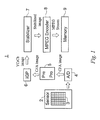
Albeit in a very schematic manner, Figure 1 shows
the function blocks of a digital video camera 1. The
video camera 1 includes an acquisition block 2
comprising an optical sensor 3.
The sensor 3, which may either a CCD (Charge
Coupled Device) or a CMOS (Complementary Metal Oxide
Semiconductor), is an integrated circuit comprising a
matrix of photosensitive cells, each of which serves to
generate an electric signal proportional to the quantity
of light that strikes it during the acquisition
interval.
In a preferred embodiment the sensor 3 comprises an
optical CFA (Colour Filter Array) filter, for example, a
Bayer filter. As is well known to persons skilled in the
art, in a sensor with a CFA filter only a single
photosensitive cell is available for acquiring a pixel.
The sensor is covered by an optical filter constituted
by a matrix (a Bayer matrix in this example) of
filtering elements, each of which is associated with a
photosensitive cell. Each filtering element transmits to
the photosensitive cell associated with it the light
radiation corresponding to the wavelength of only red
light, only green light or only blue light, so that for
each pixel it detects only one component (of which it
absorbs no more than a minimal part).
The video camera 1 also includes an analog/digital
(A/D) conversion block, indicated by the reference
number 4, to translate the generated electric signal
into a digital value with a predetermined number of bits
(generally 8, 10 or 12 bits). One may assume, solely by
way of example and without thereby introducing any
limitation whatsoever, that in the present invention the
A/D converter 4 is such as to encode the incoming analog
signals with eight-bit digital values. In that case the
digital values of the pixels will be comprised between a
minimum binary value equal to 0 and a maximum binary
value equal to 255.
On the output side of the A/D block 4 the digital
image is a CFA image, since each pixel is constituted by
just a single chromatic component (R, G or B). For this
reason, a single one-byte digital value is associated
with each pixel.
A pre-processing (PrePro) block 5, active before
and during the entire acquisition phase, is such as to
interact with the acquisition block 2 and to extract
from the CFA image a number of parameters useful for
carrying out automatic control functions: self-focusing,
automatic exposure, correction of sensor defects and
white balancing.
A block 6, the so-called IGP (Image Generation
Pipeline) block, is designed to perform a processing
phase that, starting from the digital CFA image, will
produce a complete digital image - YCrCb format, for
example - in which each pixel will have associated with
it three digital values (i.e. a total of 24 bits)
corresponding to a luminance component Y and two
chrominance components Cr and Cb. This transformation,
obtained - for example - by means of interpolation,
involves a passage from a representation of the image in
a single plane (Bayer plane), though containing
information relating to different chromatic components,
to a representation in three planes.
In digital still cameras the IGP block is commonly
realized in the form of a dedicated processor (CFA
processor), which may be, for example, in VLSI (Very
Large Scale Integration) technology.
Preferably, the IGP block 6 is also such as to
perform various functions for improving the quality of
the image, including, for example, filtering the noise
introduced by the sensor 3, applying special effects and
other functions that will generally vary from one
producer to another.
Without thereby introducing any limitation, the
video camera 1 preferably comprises a stabilizer block 7
that follows the IGP block 6 and is intended to perform
the operations relating to the stabilization method in
accordance with the present invention, so that its
output will consist of a stabilized sequence of digital
images.
This is followed by a compression/encoding block 8,
which in this example is of the MPEG type (but could
also be of other types, H263 for example), and a memory
unit 9.
When acquiring a video sequence with the video
camera 1, the sequence images are acquired consecutively
by means of the acquisition block 2, preferably within a
brief time interval between one image and the next. The
MPEG-4 standard, for example, requires fifteen images to
be acquired per second.
Hereinafter we shall use Img1, Img2, Img3, ..., Imgn-1,
Imgn, Imgn+1,... to indicate the images acquired in
sequence: Img 1 represents the first image of the
sequence to be acquired, Img2 represents the second
image, and so on.
Following acquisition, each image is passed to the
subsequent blocks, so that in all the subsequent
processing phases the images will still be processed
consecutively.
The micro-oscillations of the video camera 1 due to
involuntary micro-motions of the user's hand between one
acquisition and the next will generate image sequences
affected by unwanted motions. It should be noted that
conventionally the sequence may also contain motions
purposely introduced by the operator. During the
acquisition of a scene, for example, the operator may
want to enlarge or reduce the field of view (zooming),
or he may voluntarily move the camera to obtain a
panoramic view or follow a moving personage (panning).
Once it has been acquired, each image of the
sequence is converted into digital values by the A/D
converter 4 and then processed by the pre-processing
block 5.
After leaving the pre-processing block 5, each CFA
image is sent to the IGP block 6. In this block the
image is subjected to an interpolation phase and is thus
transformed into a complete image, for example, in YCrCb
format.
The interpolation phase may be performed, among
others, with methods that are know to a person skilled
in the art and are therefore obvious from the previous
description.
The interpolated image in YCrCb format is then sent
to the stabilizer block 7, where it undergoes processing
phase by means of a stabilization method in accordance
with the present invention. This processing phase
produces a stabilized image as its output.
It should be noted that when an image has to be
stabilized, it is conventionally required that the
unwanted motions (jiggling) should be corrected
/compensated, but without eliminating the motions
voluntarily introduced by the operator
(panning/zooming).
The choice that the stabilizer block should operate
on an image in YCrCb format constitutes a preference and
is not limitative for the purposes of the present
invention. Nor is the fact that the stabilization method
operates on interpolated to be considered as limitative:
as will subsequently be explained, a possible
alternative consists of applying the stabilization
methods to the CFA images.
Following stabilization, each image is sent to the
MPEG encoder block 8, which produces as its output a
sequence or stream of images encoded/compressed in
accordance to an MPEG-type encoding.
The MPEG stream of compressed images may be
registered in a memory unit 9 or sent to an external
peripheral device.
As shown in Figure 2, in a preferred embodiment the
stabilization method 10, performed in the stabilizer
block 7, comprises substantially three successive
phases, namely: a first phase 11 of motion estimation
(Mot_Est), a second phase 12 of unwanted motion
estimation (Unw_Mot_Est) and a third phase 13 of
unwanted motion compensation/correction (Unw_Mot_Comp).
The first phase 11 of motion estimation (Mot_Est)
is such as to estimate the motion between images of the
sequence.
The motion estimated by this phase may be due
either to a voluntary motion of the operator or to an
unwanted motion.
Referring now to Figure 3, in a preferred
embodiment the motion estimation phase 11 produces an
absolute vector of global motion absGMV[n,ref] that
comprises a translation component in the horizontal
direction absGMVx[n,ref] and a translation component in
the vertical direction absGMVY[n, ref].
The absolute global motion vector absGMV[n,ref]
represents the estimation of the translation motion of
the input image Imgn with respect to a previous image of
the sequence Imgref, which is considered as the reference
image. For the sake of simplicity, we may here assume
that the reference image is initially the first image of
the acquired sequence, so that in practice Imgref = Img 1.
Preferably, the estimation absGMV[n,ref] of the
absolute global motion vector of an input image Imgn
with respect to the reference image Imgref is produced by
estimating a global motion vector GMV[n,n-1] of the
input image Imgn with respect to the image Imgn - 1 that
immediately precedes it and then adding this vector to
the absolute global motion vector absGMV[n-1, ref]
estimated for the previous image Imgn-1. Put in
mathematical language, for each input image Imgn the
Mot_Est phase produces an output vector:
absGMV[n,ref]= GMV[n,n-1]+absGMV[n-1,ref].
Returning now to Figure 2, the second phase 12,
which estimates the unwanted motion, is such as to
produce for each image Imgn an estimation of the
unwanted motion by starting from the absolute global
motion vector absGMV[n,ref] estimated in the first
Mot_Est phase 11.
Lastly, a third phase 13 is such as to process the
input image Imgn in such a manner as to compensate the
unwanted motion on the basis of the estimation of this
motion produced in the second Unw_Mot_Est phase 12.
As already noted, the problem of estimating the
motion of the Mot_Est phase 11 is therefore that of
estimating a global motion vector between consecutive
images of the sequence.
For a given input image Imgn this global motion
vector can be advantageously estimated by starting from
the estimation of a plurality of block motion vectors,
each associated with a respective sub-block of image
pixels.
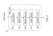
With the help of Figure 4, we shall now describe in
greater detail a particularly advantageous embodiment of
the motion estimation phase 11.
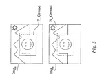
In particular, the motion estimation phase 11
comprises preferably an "area select" phase 14 which
selects two regions of the image Imgn: a first region
"B_Ground", which represents the background of the scene
reproduced by the image Imgn, and a second region
"F_Ground", which represents the foreground (see Figure
5).
As shown in Figure 5, the two regions may even be
partially superposed and is not necessary that, taken
together, they should cover the whole of the image.
As will be explained later, this preliminary
subdivision makes it possible to formulate the
stabilization strategy. For example, if the subject is
in the foreground and substantially in a fixed or only
slowly variable position, the image may be stabilized by
correcting the unwanted motions (essentially due to
vibrations of the video camera) after having estimated
this motion by means of the oscillations that can be
observed in the background of the image, i.e. by
studying the motion of the background region.
But there is also another type of unwanted motion
due to the presence of a subject moving rapidly across
the scene. In that case the person acquiring the scene
will probably not be able to appropriately "follow" the
subject. In this case, which persons skilled in the art
are wont to refer to as "tracking", the stabilization is
performed by correcting the undesired motion after
having estimated it on the basis of the motions that can
be observed in the foreground.
When acquiring real scenes, the foreground is
usually situated in a substantially central portion of
the image, while the background is situated in the
lateral and upper parts of the frame. In a preferred
embodiment the Area_Select phase could therefore select
the B_Ground and F_Ground regions in a predetermined
manner, for example, in the precise manner shown in
Figure 5.
In a variant that calls for a greater computation
effort, but also provides an optimized performance, the
selection of the regions representing the foreground and
the background could be made in a dynamic and adaptive
manner.
In yet another alternative embodiment, the
Area_Select phase 14 could select the foreground and
background regions, for example, in such a manner as to
be exactly superposed on each other, i.e. turn them into
a single region that will represent either the
background or the foreground according to a user preselected
stabilization strategy.
Hereinafter, though without thereby introducing any
limitation, we shall refer to the case in which the
Area_Select phase selects the two regions in a
predetermined manner in accordance with the preferred
subdivision shown in Figure 5.
As shown in Figure 4, the Mot_Est phase 11 also
comprises a weight calculation phase 15 indicated in the
figure as "Block_Weight".
In this phase the B_Ground and F_Ground regions are
subdivided into sub-blocks of pixels, to which we shall
hereinafter refer also with the simpler term of blocks.
These blocks may be, for example, small square blocks of
size 8x8, 16x16, 32x32. It is, of course, also possible
to make different choices as regards the size and the
shape of the blocks. It will however be advantageous to
make sure that the number of pixels in each block is
small as compared with the size (the number of pixels)
of the image.
As has already been noted, the two regions may be
partially superposed, and some of the blocks could
therefore form part of both the regions.
The weight calculation phase 15 sets out to
associate with each block of the foreground and
background regions a respective weighting coefficient W
that is correlated with some inhomogeneity measure and,
for example, will become greater as the inhomogeneity of
the block increases. For example, a block B1 that is
wholly homogeneous will be assigned a weighting
coefficient W1 equal to 1 (unity). A block B2 less
homogeneous than block B1 will be assigned a weighting
coefficient W2 greater than one.
The inhomogeneity of a block represents the lack of
uniformity existing between one or more parameters
associated with the pixels of that same block and is
therefore correlated with the spectral content of the
block in the spatial frequency domain.
The phase of evaluating the inhomogeneities, just
like the phase of calculating the block weights, serves
to identify the blocks that, given their particular
characteristics, can provide information about the
global motion of the image Imgn and possibly also serves
to discard the blocks that are not very representative
of the global motion of the image. In fact, the motion
estimation of a substantially homogeneous block (i.e. a
block with only small inhomogeneity) could be affected
by a substantial error, especially when the block is
situated in a similarly homogeneous portion of the
image. For this reason, the motion estimation of such a
block can provide completely misleading information
about the global motion of the image.
Vice versa, a block with high-frequency components
(for example: a block that has been appropriately
focused and contains neat sides or clean-cut edges) can
potentially provide very reliable information about the
global motion of the image.
In a preferred embodiment the evaluation of the
inhomogeneity of a block is performed by measuring the
inhomogeneity of the luminance component Y of the pixels
forming part of the block, since this is the component
of the image for which the human eye has the greatest
sensitivity.
In an alternative embodiment, the estimation of the
inhomogeneity could be carried out on images that have
not yet been interpolated, possibly in Bayer CFA format,
taking into consideration the green pixels. The reason
for this choice is that in this format the green pixels
are more numerous than the others and the green
component is representative of the luminance information
to within a good approximation.
It should however be noted that other pixel
parameters may also be used for measuring the
inhomogeneity, the chromatic content being a case in
point.
An inhomogeneity measure can be obtained, for
example, by calculating the variance of the block or,
more particularly, the variance of the luminance values
of the pixels of the block. For example, given a block
of size 16x16, the number of luminance values to be
taken into consideration is 64. The greater the
variance, the greater will be the inhomogeneity and
therefore the weighting coefficient W to be associated
with the block.
The variance can be calculated as:
where
Yi,j is the luminance value of the pixel
having the coordinates (i,j) in the block under
consideration,
m is the average luminance of the pixels
of the block and
N is the number of pixels in the block.
According to a preferred embodiment that implies a
comparatively small computation effort, the
inhomogeneity is estimated by calculating the mean
absolute difference MAD:
In the present invention the homogeneity is
preferably also valued by calculating the "activation"
A, which is a measure of the difference that exist
between adjacent pixels both in the horizontal and in
the vertical direction. In mathematical terms:
A = Ahor + Avert
where
Ahor is the horizontal activation and is
given by:
while
Avert is the vertical activation and is given
by:
Advantageously, the calculation of this measure
does not call for a great computational effort.
Furthermore, the activation measure values the presence
of both horizontal and vertical edges or transitions
more accurately than the two previously described
measures and is therefore particularly suitable for
characterizing the inhomogeneity of a block.
Without thereby introducing any limitation
whatsoever, the remainder of the present description
will refer to the particular case in which the
activation A is used as the inhomogeneity measure.
Once the activation has been calculated, a
weighting coefficient
W can be associated with each
block. The table below illustrates an example of a
possible association methodology:
| Activation | W |
| 0< A < 10 | 1 |
| 10 ≤ A < 500 | 2 |
| 500 ≤ A < 1000 | 4 |
| 1000 ≤ A < 2000 | 8 |
| 2000 ≤ A < 4000 | 16 |
| A ≥ 4000 | 32 |
As shown by this table, the weighting coefficients
W are assigned according to the range of values within
which the calculated activation is comprised.
Preferably, the subsequent processing operations of
the phase Mot_Est of estimating the global motion vector
of the image Imgn will take into consideration only the
blocks that have an inhomogeneity greater than a
predetermined value o or, more particularly, only blocks
having a weighting coefficient W greater than a
predetermined threshold value Wth, for example, equal to
2. For the sake of simplicity, these blocks will
henceforth be referred to as "above-threshold" blocks.
More particularly, the Mot_Est phase comprises - as
shown in Figure 4 - a further phase 16, described as
Block_Mot_Est, that associates with each block of the
image Imgn that has an above-threshold coefficient a
respective block motion vector BMV that represents the
translation motion that the block in question has
undergone in passing from the previous image Imgn-1 to
the present image Imgn .
In accordance with the present invention, any
appropriate method known to the state of the art may be
used for determining a motion vector BMV to be
associated with a given block.
On account of the advantages it provides in terms
of reliability and computational simplicity, the
algorithm described in EP-1139699 Al and the article "An
innovative, high quality and search window independent
motion estimation algorithm and architecture for MPEG-2
encoding", F.S. Rovati et al., IEEE Transactions on
Consumer Electronics, Vol.46, No.3, August 2000, will
preferably be employed for this purpose.
The conventional block motion estimation algorithm
employed in the MPEG encoder of the video camera 1 may
also be advantageously used in the method in accordance
with the present invention.
Once a respective block motion vector BMV has been
obtained for each above-threshold block, a phase 17,
known as GMV_Select, selects from among all the block
motion vectors BMV the particular block motion vector
BMV that is most representative of the global motion of
the image Imgn with respect to the previous image Imgn-1 .
To this end, starting from the weighting
coefficients W and the block motion vectors BMV
associated with the above-threshold blocks of the
background region B_Ground, the phase calculates a
global motion vector B_GMV representative of the motion
of the background region.
Similarly, starting from the weighting coefficients
W and the block motion vectors BMV associated with the
above-threshold blocks of the foreground region
F_Ground, the phase calculates a global motion vector
F_GMV representative of the motion of the foreground
region.
Preferably, the global motion vector B_GMV
representative of the motion of the background region
B_Ground will be calculated by constructing a bidimensional
histogram of the block motion vectors BMV of
the above-threshold blocks of the background region. In
this histogram each block "votes" for its associated
block vector BMV with the weighting coefficient W
assigned to it.
The phase then selects from among the possible
block motion vectors the one that has received the
largest number of "votes", i.e. the one that produces a
peak in the histogram. Let us consider, for example, the
case in which a block
B1 of the background region
B_Ground has had associated with it a block motion
vector
BMV with a horizontal component
BMVx = -1 (i.e.
translation towards the left of 1 pixel) and with a
vertical component
BMV Y = 1 (i.e. up-translation of 1
pixel) and a weighting coefficient W=4,and let us
suppose that for other above-threshold blocks
B2,B3,...,
all forming part of the background region B_Ground, the
associated block motion vectors and weighting
coefficients are as shown in the following table:
| | BMVx (pixel) | BMV Y (pixel) | W |
| B1 | -1 | 1 | 4 |
| B2 | 1 | 0 | 8 |
| B3 | -1 | 1 | 16 |
| B4 | 0 | 0 | 4 |
| B5 | 2 | 1 | 8 |
| B6 | 0 | 0 | 4 |
| B7 | -1 | -1 | 8 |
Given the data shown in this table, the bidimensional
histogram, when expressed in the form of a
table, will be as follows:
In this case the motion vector B_GMV of the
background region is motion vector BMV=(-1,1), because
this is the vector that in the histogram has accumulated
a sum of weighting coefficients W greater than any
other.
It should also be noted that a two-dimensional
histogram is not generally equivalent to two one-dimensional
histograms of, respectively, the horizontal
motion component and the vertical motion component. This
is due to the fact that the correlation between the
horizontal and vertical motion components is lost when
two separate histograms are used. At times this loss
will lead to an incorrect result.
The motion vector F_GMV representative of the
motions of the foreground region F_Ground is calculated
in a similar manner.
Lastly, the GMV_Select phase assigns to the image
Imgn a global motion vector GMV[n,n-1] by selecting one
of the two global motion vectors F_GMV and B_GMV
calculated for the two regions as explained above.
With a view to performing this selection operation,
it counts the number N1 of the blocks with which the
Mot_Est phase associated a motion vector equal to the
global motion vector B_GMV chosen - by means of the
histogram -as being representative of the motion of the
background B_Ground.
Similarly, it will count the number N2 of blocks of
the foreground region F_Ground with which the
Block_Mot_Est phase associated a motion vector equal to
the global motion vector F_GMV chosen - by means of the
histogram - as being representative of the motion of the
foreground F_Ground.
The GMV_Select phase 17 selects the global motion
vector of the background region B_Ground when N1 is
greater than N2, and vice versa in the contrary case. In
this case one thus has
GMV [n, n -1 ] =B_GMV,
while in the contrary case one has
GMV[n,n-1]=F_GMV.
Advantageously, rather than being actually counted,
the numbers N1 and N2 can be estimated to within a good
approximation by means of the following formulas:
N 1 = NBB_Ground TWB_Ground IB _Ground [B_GMV]
where NBB_Ground is the number of above-threshold
blocks in the background region B_Ground, TWB _ Ground is
the sum of all the values in the histogram (i.e. the sum
of all the weighting coefficients associated with above-threshold
blocks of the background region), and
IB _ Ground [B _GMV] is the histogram value of the vector
B_GMV, i.e. the peak value of the histogram.
Similarly, the phase estimates:
N 2 = NBF_Ground TWF_Ground IF_Ground [F_GMV].
When the numbers N1 and N2 are estimated as shown
above, one obtains an optimization of the necessary
memory resources or an analogous computational saving,
because the calculation is entirely based on data
already contained in the histograms.
Once the vector GMV[n, n-1] representative of the
motion of the motion of the image Imgn with respect to
the image Imgn - 1 , has been calculated, a final phase 18,
designated as absGMV Eval, of the motion estimation
phase 11 calculates the absolute motion absGMV[n,ref] of
the image Imgn with respect to the image Imgn-1 of the
sequence as previously explained.
On completion of the motion estimation phase 11,
unwanted motion estimation phase 12 (Unw_Mot_Est)
estimates the unwanted motion from the absolute global
motion vector absGMV[n, ref] of the image Imgn.
Going into greater detail, the two translation
components in the horizontal and the vertical direction
of the absolute global motion vector of the image Imgn
are taken into individual consideration in this phase,
because there exists the possibility, for example, that
estimated movement in the vertical direction is due to
vibration (jiggling) and therefore unwanted, whereas the
motion in the horizontal direction is due a panoramic
shot (panning) and has therefore been purposely
introduced by the operator.
It has been noted that undesired motion having the
characteristics of a random vibration will typically
have a small amplitude and a zero mean value as compared
with the reference image (because it rapidly changes
direction).
Purposely-introduced motion, on the other hand, can
attain large amplitudes and maintain the same direction
for a long time. One need only think, for example, of
the case in which the operator acquires a sequence by
swivelling the camera around himself and always in the
same direction. In some cases such voluntary movements
could even grow indefinitely and cause a situation of
arithmetic overflow, i.e. grow to a value that exceeds
the largest number that can be represented by the memory
quantity reserved therefor.
For the sake of simplicity, we shall henceforth
describe the unwanted movement estimation phase 12 with
sole reference to the motion component of the image Imgn
in the horizontal direction. The manner in which the
component in the vertical direction is estimated will be
rendered obvious by this description.
It should however be borne in mind that the phase
of estimating the unwanted motion Unw_Mot_Est about to
be described is performed in accordance with a preferred
methodology. But numerous alternatives, all well known
to persons skilled in the art, can also be used for this
purpose.
In a preferred embodiment the unwanted motion
estimation phase Unw_Mot_Est compares the horizontal
component absGMVx[n,ref] of the absolute global motion
vector absGMV[n,ref] estimated for the image Imgn with a
predetermined threshold value, which we shall henceforth
refer to as the as the horizontal compensation threshold T hor / c om p.
If the horizontal component absGMVx[n,ref] has an
amplitude smaller - the amplitude to be considered being
that of the module - than the compensation threshold
T hor / c om p, the horizontal component is associated with an
unwanted motion, i.e. it is established that the
horizontal motion component is due to an undesired
motion. Otherwise the horizontal motion is associated
with a purposely-introduced motion.
A horizontal component associated with an undesired
motion activates the subsequent unwanted motion
compensation (or Unw_Mot_Comp) phase 13, which
horizontally translates the image Imgn in the direction
opposite to that of the horizontal component and by a
number of pixels equal to the amplitude of the
horizontal component Imgn, of the absolute global motion
vector.
On the other hand, when the horizontal component
absGMVx[n,ref] has an amplitude greater than or equal to
the compensation threshold, the motion is considered to
be voluntary and the subsequent unwanted motion
compensation phase 13 is not activated for the
horizontal component, on which there is imposed the
value
|absGMVx[n,ref]| = Thor c om p ·
The absolute motion vector is thus modified by
making the amplitude of the horizontal component
associated with a voluntary motion equal to the
horizontal compensation threshold. In other words, its
amplitude is fixed at a value that coincides with the
compensation threshold.
This has the advantage of making it possible to
avoid this amplitude growing indefinitely when the
horizontal motion component maintains the same direction
for a long period of time.
In this case, when the next image Imgn+1 is being
stabilized, the motion estimation phase 11 will estimate
the horizontal component of the absolute global motion
vector of the image Imgn+1 by means of the following
formula:
absGMVx [n+1, ref] = GMVx [n+1, n] + absGMVx [n, ref] =
= GMVx[n+1,n]+ T hor com p ·
When the amplitude of the horizontal component
absGMVx[n+1,ref] calculated in this manner is smaller
than the compensation threshold T hor / c om p, the horizontal
motion component GMVx[n+1,n] is interpreted as an
unwanted horizontal vibration, because its direction is
contrary to the direction of the wanted motion, and the
compensation phase 13 is therefore activated.
It should be noted that this method of estimating
the unwanted motion will also interpret the initial part
of a voluntary motion as an unwanted motion (and will
therefore correct/compensate it) until the compensation
threshold is exceeded. Once this critical point has been
passed, the remainder of the wanted motion is correctly
interpreted and will not therefore be
corrected/compensated. In any case, the erroneously
corrected/compensated part of such a voluntary motion
would be negligible, because these motions - by their
very nature - are normally very extensive.
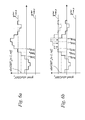
Figures 6a and 6b illustrate the variations in the
course of time of the horizontal components of the
absolute motion vectors of an image sequence. In
particular, Figure 6a shows the variations in time of
the horizontal components of the absolute motion vectors
that would be observed on the output side of the Mot_Est
phase if the horizontal components having an amplitude
greater than or equal to the compensation threshold were
not to be modified.
Figure 6b, on the other hand, illustrates the time
behaviour of the absolute motion vectors after they have
been modified in phase 13, the Unw_Mot_Comp phase. As
can be seen, the component having an amplitude greater
than the threshold are modified in such a way as to have
an amplitude equal to the threshold. In Figure 6b the
horizontal motion is interpreted as unwanted as far as
image Imgn-1. But from image Imgn onwards and as far as
image Imgn+3 the motion is interpreted as wanted. From
image Imgn+4 onwards, lastly, it is again interpreted as
unwanted.
Preferably, the method in accordance with the
present invention will be such as to provide for the
compensation threshold - in this case horizontal - to be
adaptively modified on the basis of its previous
history. Indeed, should it be noted that wanted motion
predominates in the estimated horizontal motion, so that
compensation/correction is applied only rarely (i.e. few
images are being stabilized), the horizontal
compensation threshold will be raised, thus rendering
the method more sensitive to unwanted horizontal
motions. But when corrections/compensations predominate
and wanted motion is only rarely detected, the threshold
will be lowered.
Advantageously, moreover, the value of the absolute
global motion vector can be reduced at the end of a
wanted motion (for example, it can be made equal to the
compensation threshold) in order to render the
stabilization more efficient in detecting unwanted
motions having opposite directions.
As already explained, the unwanted motions are
compensated/corrected in the unwanted motion
compensation phase 13.
In this phase, for example, the image Imgn will be
appropriately translated in the vertical/horizontal
direction as previously described in order to compensate
the unwanted motion.
As will be obvious to a person skilled in the art,
the translation phase will preferably be followed by an
appropriate phase of re-dimensioning the image Imgn,
because the translation will cause a part of the image
to be lost/discarded. An enlargement phase may also be
introduced. These phases are already known, and for this
reason need no further explanation here.
In actual practice the method of stabilization in
accordance with the present invention has been found not
only to provide a reliable and robust estimate of the
movement of a sequence, but also to be capable of
appropriately distinguishing unwanted motions that have
to be stabilized from purposely introduced motions.
Advantageously, moreover, the subdivision of the
image into a region that represents the background and a
region that represents the foreground makes it possible
to obtain a motion estimation and an image stabilization
that will be optimised in relation to the image content.
The possibility of choosing predefined and even
partially superposed background and foreground regions
also makes it possible for the stabilization method to
be applied in a very flexile manner to sequences in
which these regions are arranged in many different ways
and have various sizes. It should be noted that this
superposition does not imply any additional computation
cost, because the weighting coefficients W and the block
motion vectors BMV still have to be calculated only once
for regions that form part of both blocks.
In the present invention the estimation of the
motion vector representative of the motion of an entire
image is obtained by using an inhomogeneity measure of
image blocks suitable for evaluating the reliability of
these blocks on the basis of their respective frequency
contents. This measure, in particular, is used for
selecting one of multiplicity of block motion vectors as
representative of the image motion.
It should be noted that, thanks to the evaluation
of the inhomogeneity of each block, the blocks that are
not capable of providing reliable information about the
image motion are discarded before the calculation of the
block motion vectors, thus avoiding unproductive
computational efforts.
It is also important to note that in the present
invention the inhomogeneity information serves not only
to discard unreliable blocks, but is also used for
weighting the reliability of the non-discarded blocks
for the purposes of obtaining the global motion vector
of the image.
Another advantage derives from the fact that the
method exploits the information of a large number of
blocks, so that a possible block characterized by a
considerable inhomogeneity (and therefore giving rise to
a large weighting coefficient) but with a motion that is
not representative of the image motion (due, for
example, to the presence of moving objects in the scene)
will have practically no influence on the image motion
estimation if many other blocks provide correct
information.
As far as memory occupation is concerned, it should
be noted that it is also advantageous the fact that the
information regarding the past history of the sequence
motion is cumulatively contained in a single absolute
global motion vector. It should also be noted that the
discrimination between wanted and unwanted motions is
obtained by means of a simple comparison with a
threshold value and, consequently does not call for a
considerable computation effort.
The modification of the horizontal/vertical motion
components that exceed their respective threshold values
makes it possible to avoid the drawback of an indefinite
growth of these components and gives rise to the further
advantage of providing a stabilization method capable of
reacting quickly to unwanted movements of small
amplitude that occur between wanted motions that may
sometimes be of considerable duration.
Unusually, moreover, the possibility of exploiting
a block motion estimate provided in this manner by a
conventional MPEG encoder offers substantial advantages
in economic terms.
It should also be borne in mind that, even though
it has here been described as part of a stabilization
method, the motion estimation method in accordance with
the present invention need not necessarily be employed
for this purpose. For example, it could be alternatively
and advantageously be used for estimating the motion of
any kind of sequence of digital or digitalized
photograms in alignment/registration techniques for
photographic applications.
Obviously, a person skilled in the art, especially
when having to satisfy contingent and specific needs,
could introduce numerous modifications and variants into
the stabilization method as described above, though
without thereby overstepping the protection limits of
the invention as defined by the claims set out
hereinbelow.