EP1380469A2 - Lighting device for vehicles - Google Patents
Lighting device for vehicles Download PDFInfo
- Publication number
- EP1380469A2 EP1380469A2 EP03102059A EP03102059A EP1380469A2 EP 1380469 A2 EP1380469 A2 EP 1380469A2 EP 03102059 A EP03102059 A EP 03102059A EP 03102059 A EP03102059 A EP 03102059A EP 1380469 A2 EP1380469 A2 EP 1380469A2
- Authority
- EP
- European Patent Office
- Prior art keywords
- light
- light guide
- cross
- lighting device
- surface areas
- Prior art date
- Legal status (The legal status is an assumption and is not a legal conclusion. Google has not performed a legal analysis and makes no representation as to the accuracy of the status listed.)
- Withdrawn
Links
Images


Classifications
-
- G—PHYSICS
- G02—OPTICS
- G02B—OPTICAL ELEMENTS, SYSTEMS OR APPARATUS
- G02B6/00—Light guides; Structural details of arrangements comprising light guides and other optical elements, e.g. couplings
- G02B6/0001—Light guides; Structural details of arrangements comprising light guides and other optical elements, e.g. couplings specially adapted for lighting devices or systems
-
- B—PERFORMING OPERATIONS; TRANSPORTING
- B60—VEHICLES IN GENERAL
- B60Q—ARRANGEMENT OF SIGNALLING OR LIGHTING DEVICES, THE MOUNTING OR SUPPORTING THEREOF OR CIRCUITS THEREFOR, FOR VEHICLES IN GENERAL
- B60Q3/00—Arrangement of lighting devices for vehicle interiors; Lighting devices specially adapted for vehicle interiors
- B60Q3/60—Arrangement of lighting devices for vehicle interiors; Lighting devices specially adapted for vehicle interiors characterised by optical aspects
- B60Q3/62—Arrangement of lighting devices for vehicle interiors; Lighting devices specially adapted for vehicle interiors characterised by optical aspects using light guides
- B60Q3/64—Arrangement of lighting devices for vehicle interiors; Lighting devices specially adapted for vehicle interiors characterised by optical aspects using light guides for a single lighting device
-
- B—PERFORMING OPERATIONS; TRANSPORTING
- B60—VEHICLES IN GENERAL
- B60Q—ARRANGEMENT OF SIGNALLING OR LIGHTING DEVICES, THE MOUNTING OR SUPPORTING THEREOF OR CIRCUITS THEREFOR, FOR VEHICLES IN GENERAL
- B60Q3/00—Arrangement of lighting devices for vehicle interiors; Lighting devices specially adapted for vehicle interiors
- B60Q3/70—Arrangement of lighting devices for vehicle interiors; Lighting devices specially adapted for vehicle interiors characterised by the purpose
- B60Q3/76—Arrangement of lighting devices for vehicle interiors; Lighting devices specially adapted for vehicle interiors characterised by the purpose for spotlighting, e.g. reading lamps
Definitions
- the invention relates to a lighting device for a vehicle, in particular an interior lamp, with at least one lamp and at least one this assigned light collecting part,
- the illuminant is an ellipsoidal reflector Assigned light collector, which is the light emitted by the illuminant bundles.
- the light beam generated in this way is in one end of a light guide coupled, the other end of a spot to be illuminated is facing. This is guided in the side of the light guide Reflected light using total reflection.
- the opening angle at which the light beam emerges from the light guide corresponds to the opening angle that the Bundle of light before entering the light guide.
- the light guide shines in relatively narrow beam of light.
- the light emitted by an incandescent lamp without the Coupling directly into a light guide using a light collecting part has a larger one Opening angle on than in the arrangement already mentioned with light collecting part.
- the opening angle of the light beam coupled into the light guide is on the one hand from the distance between the emission point of the illuminant and the light entry surface of the Light guide and on the other hand also on the dimensions of the light entry surface dependent. Because here too the opening angle of the light beam when passing through is retained approximately by the light guide, results compared to an illumination device with a light collector also a correspondingly larger opening angle of the light bundle emerging from the light guide.
- the opening angle can be increased by increasing the distance between the Illuminants and the light entry surface are reduced, however, takes in the The amount of light coupled in with increasing distance between the Illuminant and the light entry surface, so that then only a relative poor efficiency of the lighting device results in 0. This is particularly so unfavorable when using a lamp that has a large beam angle Light emits because there is a large distance between the illuminant and the light coupling area is only a very small part of that Illuminant emitted light is coupled into the light guide.
- the converging lens By intermediary a converging lens between the illuminant and the light coupling surface the optical efficiency of the lighting device can be increased
- the converging lens must then have a relatively large diameter have because the illuminant to achieve a light beam with small Opening angle approximately at the focal point of the converging lens and thus in a relatively large one Distance from the converging lens must be arranged.
- the light collecting part as a light guide at least one light entry surface facing the illuminant and at least a spaced-apart light exit surface is formed that the light guide at least two between the light entry surface and the light exit surface side surface regions arranged opposite one another on its outer circumference on which the light guided in the light guide of total reflection subject, and that these side surface areas for focusing the light in such a way run obliquely to each other so that the cross section of the light guide, starting from from the light entry surface to the light exit surface.
- the light bundle guided in the light guide thus emerges from the light guide has a smaller opening angle than before entering the light guide, i.e. the Light rays are "parallelized" when they pass through the light guide.
- the light entry surface of the light bundle element can be close to the light emission point of the lamp can be arranged, the distance between the Light entry surface and the light beam element, possibly even to zero can be reduced.
- an almost complete one can easily be Coupling of the light emitted by the illuminant into the light guide be achieved, i.e. the light beam is almost lossless.
- they extend in pairs mutually assigned side surface areas only over part of the longitudinal extent of the light guide, the light guide in the remaining part of its longitudinal extent at least in sections, preferably a constant cross section having. This measure allows the cross-sectional dimension for a long light guide be limited at the light exit end of the light guide.
- the light guide has at least a first and a second pair of mutually opposite, oblique mutually extending rare surface areas, the direction in which the side surface areas of the first pair are opposite, transverse to that Direction is arranged in which the side surface areas of the second pair are opposite.
- the side surface areas are in the circumferential direction of the Light guide arranged offset to each other.
- the cross section of the light guide can vary expand from a square to a larger square, for example. This in The light guided in the light guide is then in different, transverse to each other extending longitudinal planes of the light guide bundled.
- the light guide at least a first and a second Pair of opposite, diagonally extending Has side surface areas, and that these pairs in the longitudinal direction of the light parent are arranged offset to one another. If necessary, between the mutually offset side surface areas with a light guide section its length can be arranged constant cross-section. Also through these measures a desired light beam can be achieved. It is special possible, the light only in a certain, transverse to the longitudinal extension of the Light guide lying. Bundle level.
- they are each between the side surface areas lying opposite each other in pairs included opening angle in at least two pairs of these side surface areas different sized. If this side surface area in the circumferential direction of the light guide are offset from each other, there is an asymmetrical Light collection.
- a light beam with a rectangular shape can also be used Cross section when passing through the light guide in a light bundle with a square Cross-section be mined.
- the cross section widens of the light guide along the sloping side surface areas from a first cross-sectional shape to a second cross-sectional shape, the second cross-sectional shape corresponds to an extension of the first cross-sectional shape.
- the Optical fiber is then simple in the development of the lighting device Conceivable, for example, using a CAD system.
- the cross-sectional shape of the lighting device can correspond to the respective Desired radiation characteristics of the lighting device can be selected.
- the first cross-sectional shape is a circle and the second cross-sectional shape an ellipse.
- the light guide can be used as Plastic injection molded part can be formed, the geometry of the light guide comparatively inexpensive manufacture of the for the manufacture of the light guide necessary injection molding tool.
- the light guide is also easy to use remove from the injection mold.
- the illuminant assigned to the light guide preferably has a point or circular disk-shaped light emission, which good light coupling into the circular first cross-sectional shape of the light guide allows.
- the Cross section of the light guide along the oblique side surface areas from a circular shape to a cross-sectional shape by two Semicircles and two parallel connecting the ends of these semicircles Straight line is limited.
- this embodiment compared to that a different light distribution with an elliptical exit cross-section.
- the light exit surface has at least one slope that is orthogonal to the longitudinal extension of the light guide arranged plane is inclined, where appropriate at least two of these slopes by at least one step or a paragraph are arranged offset to each other.
- the main direction of emission of the light beam is then inclined at an angle to the longitudinal axis of the light guide.
- At least one illuminant is designed as a surface spotlight, in particular as an electroluminescent film or organic light emitting diode (oLED).
- the Surface spotlights can then be arranged close to the light entry surface of the light guide be so that almost all of the light emitted by the surface radiator can be bundled by means of the light guide.
- One as an interior light for ambient lighting of an interior 1 of a Lighting device designed for vehicle 2 has a carrier part 3 (FIG. 1), on which a lamp 4 and a light guide 5 assigned to it are arranged are.
- the illuminant 4 is designed as a light-emitting diode, which is on one in the drawing Circuit board, not shown, is mounted, the electrical connections for connecting to a power supply (battery) of the vehicle 2.
- the Printed circuit board is on the interior 1 of the vehicle 2 in the use position facing away from the back of the support member 3 and located there Attachment points connected to this.
- the illuminant 4 is behind one Positioned opening 6 which passes through the carrier part 3. In this opening 6 is the Light guide 5 used.
- the light guide 5 is rod-shaped and has a light entry surface 7 at one end facing the illuminant 4 and at its other end facing the interior 1 a light exit surface 8.
- the normal to the outer surface of the light guide 5 is arranged relative to the light beams 9 guided in the light guide 5 such that these are subject to total reflection when they hit the lateral surface.
- the light guide 5 is designed as a light collector, which through the light guide 5 bundles light passing through such that the opening angle ⁇ of the from the Light guide 5 emerging light bundle is smaller than the opening angle ⁇ of Bundle of light before entering the light guide 5. This is achieved in that the outer circumference of the light guide 5 diametrically opposite each other Side surface areas 10 of the light guide 5 so inclined to each other run that the cross section of the light guide 5, starting from the light entry surface 7 to the light exit surface 8. In orthogonal to the longitudinal central axis of the light guide 5 arranged levels run the rare surface areas 10th point symmetrical to the longitudinal center axis of the light guide 5.
- the angle is reduced, under which the light rays 9 to the longitudinal direction Pf or to the longitudinal central axis of the light guide 5 are inclined in the reflection of the light rays 9 to the Side surface areas 10 each by double, between each other opposite side surface areas 10 included opening angle ⁇ of the light guide 5.
- this effect in the Light rays 9, which strongly before entering the light guide 5 against its longitudinal direction Pf are particularly effective since these light beams 9 several times on the side surface regions 10 which run obliquely to one another be reflected.
- the light guide 5 has several, approximately stripes in the longitudinal direction Pf, each diametrical mutually opposite side surface areas 10, which in the circumferential direction of the light guide 5 are arranged offset to one another. They are each between the diametrically opposite side surface areas 10 included opening angle ⁇ in diameter planes that are transverse to each other run, different sizes. This is achieved by the fact that the Cross section of the light guide 5 starting from the light entry surface 7 to the light exit surface 8 from a circular cross section to an elliptical cross section expands, the elliptical cross section by stretching the circular Cross-section is formed. This results in cross-mutually Diameter directions of the light guide 5 a different light beam.
- the Direction in which the circular cross section by stretching in the elliptical Cross section is convertible, is transverse in the use position of the interior light and in particular at right angles to the longitudinal axis 12 of the vehicle 2 or to the latter Direction of travel arranged.
- the interior light emits an oval beam of light from whose largest cross-sectional dimension in the direction of the longitudinal axis 12 of the Vehicle 2 is oriented.
- 4 is the interior light of the vehicle 2 by means of the interior light projected oval light spot marked with a dash-dotted line 13. It is clear recognizable that the light distribution is selected such that one on the driver's seat 14 or the passenger seat 15 sitting by the light of the interior light is illuminated or dazzled. This means that the interior light can operate during the night of the vehicle must be switched on constantly while driving to the between the driver's seat 14 and the passenger seat 15 interior, such e.g. a center console to illuminate uniformly. 4 is for comparison with a dotted line 16 denotes yet another light spot, which is at a Interior lamp with rotationally symmetrical light emission would result.
- the light guide 4 has the Illuminant 4 facing end on a square cross-section, which faces the opposite end of the light guide 4 facing the interior 5 continuously to a square cross section with larger dimensions expands.
- the light guide 4 thus has the shape of an obelisk.
- the light guide 4 can also have other angular basic shapes and for example, be formed as a truncated pyramid.
- As the illuminant 4 is in the 5 an area coated with a phosphor Electroluminescent film provided.
- the light exit surface 8 has several Slopes 11, which are orthogonal to the longitudinal direction Pf of the light guide 5 arranged plane are inclined.
- the slopes 11 are each strip-shaped and with their longitudinal extension transverse to their direction of inclination oriented. Slopes arranged next to each other next to each other 11 are oriented parallel to one another with their extension planes. It is a step or a paragraph is provided between each of these slopes 11.
- the Slants 11 at different angles to the orthogonal to Longitudinal direction Pf of the light guide 4 arranged plane may be inclined can.
- the direction of inclination is Slopes 11 are oriented such that the light beam from the windshield 17 of the vehicle 2 is shifted towards the center of the vehicle.
- a light spot is also marked with the dashed line 18 in FIG. 4, which would result in an interior lamp in which the light exit surface is arranged orthogonally to the longitudinal direction Pf of the light guide 5.
- the light collecting part is a light guide 5 at least one light entry surface 7 and at least one spaced-apart light exit surface 8 is formed.
- the light guide 5 has between the light entry surface 7 and the light exit surface 8 at least two oppositely arranged on its outer circumference Side surface areas 10 on which the light guided in the light guide 5 is subject to total reflection.
- the side surface areas 10 run for bundling of the light so obliquely to one another that the cross section of the light guide 5, expanding from the light entry surface 7 to the light exit surface 8.
Abstract
Description
Die Erfindung betrifft eine Beleuchtungseinrichtung für ein Fahrzeug, insbesondere eine Innenleuchte, mit wenigstens einem Leuchtmittel und mindestens einem diesem zugeordneten Lichtsammelteil,The invention relates to a lighting device for a vehicle, in particular an interior lamp, with at least one lamp and at least one this assigned light collecting part,
Eine derartige Beleuchtungseinrichtung, die als Leuchtmittel eine Glühlampe aufweist, ist aus der Praxis bekannt. Dem Leuchtmittel ist ein Ellipsoid-Reflektor als Lichtsammeltell zugeordnet, der das von dem Leuchtmittel abgegebene Licht bündelt. Das auf diese Weise erzeugte Lichtbündel wird in eine Ende eines Lichtleiters eingekoppelt, der mit seinem anderen Ende einer zu beleuchteten Stelle zugewandt ist. An den Seitenflächen des Lichtleiters wird das in diesem geführte Licht unter Ausnutzung der Totalreflexion reflektiert. Der Öffnungswinkel, unter dem das Lichtbündel aus dem Lichtleiter austritt, entspricht dem Öffnungswinkel, den das Lichtbündel vor dem Eintritt in den Lichtleiter hatte. Der Lichtleiter strahlt also ein relativ enges Lichtbündel ab.Such a lighting device that uses an incandescent lamp is known from practice. The illuminant is an ellipsoidal reflector Assigned light collector, which is the light emitted by the illuminant bundles. The light beam generated in this way is in one end of a light guide coupled, the other end of a spot to be illuminated is facing. This is guided in the side of the light guide Reflected light using total reflection. The opening angle at which the light beam emerges from the light guide corresponds to the opening angle that the Bundle of light before entering the light guide. The light guide shines in relatively narrow beam of light.
Es ist auch bereits bekannt, das von einer Glühlampe abgestrahlte Licht ohne die Verwendung eines Lichtsammelteils direkt in einen Lichtleiter einzukoppeln. In diesem Fall weist das in den Lichtleiter eingekoppelte Lichtbündel einen größeren Öffnungswinkel auf als bei der bereits erwähnten Anordnung mit Lichtsammelteil. Der Öffnungswinkel des in den Lichtleiter eingekoppelten Lichtbündels ist einerseits von dem Abstand der Abstrahlstelle des Leuchtmittels zu der Lichteintrittsfläche des Lichtleiters und andererseits aber auch von den Abmessungen der Lichteintrittsfläche abhängig. Da auch hier der Öffnungswinkel des Lichtbündels beim Durchtritt durch den Lichtleiter in etwa erhalten bleibt, ergibt gegenüber einer Beleuchtungseinrichtung mit Lichtsammeltell auch ein entsprechend größerer Öffnungswinkel des aus dem Lichtleiter austretenden Lichtbündels.It is also known that the light emitted by an incandescent lamp without the Coupling directly into a light guide using a light collecting part. In In this case, the light beam coupled into the light guide has a larger one Opening angle on than in the arrangement already mentioned with light collecting part. The opening angle of the light beam coupled into the light guide is on the one hand from the distance between the emission point of the illuminant and the light entry surface of the Light guide and on the other hand also on the dimensions of the light entry surface dependent. Because here too the opening angle of the light beam when passing through is retained approximately by the light guide, results compared to an illumination device with a light collector also a correspondingly larger opening angle of the light bundle emerging from the light guide.
Zwar kann der Öffnungswinkel durch Vergrößern des Abstands zwischen dem Leuchtmittel und der Lichteintrittstfläche reduziert werden, jedoch nimmt die in den Lichtleiter eingekoppelte Lichtmenge mit zunehmendem Abstand zwischen dem Leuchtmittel und der Lichteintrittsfläche ab, so dass sich dann nur noch ein relativ schlechter Wirkungsgrad der Beleuchtungseinrichtung ergibt0. Dies ist insbesondere bei Verwendung eines Leuchtmittels ungünstig, das unter einem großen Abstrahlwinkel Licht abstrahlt, da dann bei einem großen Abstand zwischen dem Leuchtmittel und der Lichteinkoppelfläche nur noch ein sehr geringer Teil des von dem Leuchtmittel abgestrahlten Lichts in den Lichtleiter eingekoppelt wird. Durch Zwischenschaltung einer Sammellinse zwischen Leuchtmittel und Lichteinkoppelfläche kann der optische Wirkungsgrad der Beleuchtungseinrichtung zwar gestelgert werden, jedoch muss die Sammellinse dann einen relativ großen Durchmesser aufweisen, weil das Leuchtmittel zur Erzielung eines Lichtbündels mit kleinem Öffnungswlnkel etwa im Brennpunkt der Sammellinse und somit in relativ großer Entfernung von der Sammellinse angeordnet sein muss.Although the opening angle can be increased by increasing the distance between the Illuminants and the light entry surface are reduced, however, takes in the The amount of light coupled in with increasing distance between the Illuminant and the light entry surface, so that then only a relative poor efficiency of the lighting device results in 0. This is particularly so unfavorable when using a lamp that has a large beam angle Light emits because there is a large distance between the illuminant and the light coupling area is only a very small part of that Illuminant emitted light is coupled into the light guide. By intermediary a converging lens between the illuminant and the light coupling surface the optical efficiency of the lighting device can be increased However, the converging lens must then have a relatively large diameter have because the illuminant to achieve a light beam with small Opening angle approximately at the focal point of the converging lens and thus in a relatively large one Distance from the converging lens must be arranged.
Es besteht deshalb die Aufgabe, eine Beleuchtungseinrichtung der eingangs genannten Art zu schaffen, die bei einem einfachen Aufbau eine Bündelung des von dem Leuchtmittel abgestrahlten Lichts ermöglicht. Dabei soll die Beleuchtungseinrichtung auch bei einem Leuchtmittel, das unter einem großen Abstrahlwinkel Licht abstrahlt, eine gute Ausnutzung des von dem Leuchtmittel abgestrahlten Lichts ermöglichen.There is therefore the task of a lighting device at the beginning mentioned type to create a bundling of a simple structure light emitted by the illuminant. The lighting device should even with a lamp that has a large beam angle Light emits, a good use of the light emitted by the lamp enable.
Diese Aufgabe wird dadurch gelöst, dass das Lichtsammelteil als Lichtleiter mit wenigstens einer dem Leuchtmittel zugewandten Lichteintrittsfläche und zumindest einer davon beabstandeten Lichtaustrittsfläche ausgebildet ist, dass der Lichtleiter zwischen der Lichteintrittsfläche und der Lichtaustrittsfläche wenigstens zwei an seinem Außenumfang einander gegenüberliegend angeordnete Seitenflächenbereiche aufweist, an denen das in dem Lichtleiter geführte Licht der Totalreflexion unterliegt, und dass diese Seitenflächenbereiche zum Bündeln des Lichts derart schräg zueinander verlaufen, dass sich der Querschnitt des Lichtleiters, ausgehend von der Lichteintrittsfläche zu der Lichtaustrittsfläche, aufweitet.This task is solved by using the light collecting part as a light guide at least one light entry surface facing the illuminant and at least a spaced-apart light exit surface is formed that the light guide at least two between the light entry surface and the light exit surface side surface regions arranged opposite one another on its outer circumference on which the light guided in the light guide of total reflection subject, and that these side surface areas for focusing the light in such a way run obliquely to each other so that the cross section of the light guide, starting from from the light entry surface to the light exit surface.
In vorteilhafter Weise reduziert sich dadurch bei jeder Reflexion der in dem Lichtleiter geführten Lichtstrahlen an den schräg zueinander verlaufenden Seitenflächenbereichen der Winkel, unter dem die Lichtstrahlen zur Längserstreckungsrichtung des Lichtleiters geneigt sind. Dabei findet bei jeder Reflexion eine Verengung des in dem Lichtleiter geführten Lichtbündels um den doppelten, zwischen den Seitenflächenbereichen des Lichtleiters eingeschlossenen Öffnungswinkel des Lichtleiters statt. Dieser Effekt ist für stark gegen die Längserstreckung des Lichtleiters geneigte Lichtstrahlen besonders effektiv, da diese an den Seitenflächenbereichen öfter reflektiert werden als weniger stark geneigte Lichtstrahlen. Lichtstrahlen, die bereits unmittelbar nach dem Durchtritt durch die Lichteintrittsfläche parallel zur Achse des Lichtleiters verlaufen, bleiben unverändert, da sie nicht reflektiert werden. Nach dem Austreten aus dem Lichtleiter weist das in dem Lichtleiter geführte Lichtbündel somit einen kleineren Öffnungswinkel auf als vor dem Eintritt in den Lichtleiter, d.h. die Lichtstrahlen werden beim Durchtritt durch den Lichtleiter "parallelisiert". Da eine derartiges, als Lichtleiter ausgebildetes Lichtsammelteil im Unterschied zu einem Linsenelement oder einem Fokussierspiegel keinen definierten Brennpunkt aufweist, kann die Lichteintrittsfläche des Lichtbündel-Elements bellebig nahe an der Lichtabstrahlstelle des Leuchtmittels angeordnet sein, wobei der Abstand zwischen der Lichteintrittsfläche und dem Lichtbündel-Element gegebenenfalls sogar auf Null reduziert sein kann. Somit kann auf einfache Weise eine nahezu vollständige Einkoppelung des von dem Leuchtmittel abgestrahlten Lichts in den Lichtleiter erreicht werden, d.h. die Lichtbündelung erfolgt nahezu verlustfrei.This advantageously reduces the reflection in the light guide with each reflection guided light rays on the oblique side surface areas the angle at which the light rays are directed to the longitudinal direction of the light guide are inclined. With each reflection there is a narrowing of the in the light guide guided around the double, between the side surface areas of the light guide included opening angle of the light guide instead of. This effect is strongly inclined against the longitudinal extension of the light guide Beams of light are particularly effective because they appear more often on the side areas are reflected as less inclined light rays. Rays of light that already immediately after passing through the light entry surface parallel to the axis of the Light guides run unchanged, since they are not reflected. After this The light bundle guided in the light guide thus emerges from the light guide has a smaller opening angle than before entering the light guide, i.e. the Light rays are "parallelized" when they pass through the light guide. There one such, designed as a light guide light collecting part in contrast to one Lens element or a focusing mirror has no defined focal point, the light entry surface of the light bundle element can be close to the light emission point of the lamp can be arranged, the distance between the Light entry surface and the light beam element, possibly even to zero can be reduced. Thus, an almost complete one can easily be Coupling of the light emitted by the illuminant into the light guide be achieved, i.e. the light beam is almost lossless.
Bei einer vorteilhaften Ausführungsform der Erfindung erstrecken sich die paarweise einander zugeordneten Seitenflächenbereiche nur über einen Teil der Längserstreckung des Lichtleiters, wobei der Lichtleiter in dem übrigen Teil seiner Längserstreckung zumindest abschnittweise einen vorzugsweise konstanten Querschnitt aufweist. Durch diese Maßnahme kann bei einem langen Lichtleiter die Querschnittsabmessung am Lichtaustrittsende des Lichtleiters begrenzt werden.In an advantageous embodiment of the invention, they extend in pairs mutually assigned side surface areas only over part of the longitudinal extent of the light guide, the light guide in the remaining part of its longitudinal extent at least in sections, preferably a constant cross section having. This measure allows the cross-sectional dimension for a long light guide be limited at the light exit end of the light guide.
Bei einer bevorzugten Ausgestaltung der Erfindung weist der Lichtleiter zumindest ein erstes und ein zweites Paar jeweils einander gegenüberliegender, schräg zueinander verlaufender Seltenflächenbereiche auf, wobei die Richtung, in der sich die Seitenflächenbereiche des ersten Paares gegenüberliegen, quer zu der Richtung angeordnet ist, in der sich die Seitenflächenbereiche des zweiten Paares gegenüberliegen. Die Seitenflächenbereiche sind dabei in Umfangsrichtung des Lichtleiters zueinander versetzt angeordnet. Der Querschnitt des Lichtleiters kann sich dabei beispielsweise von einem Quadrat in ein größeres Quadrat aufweiten. Das in dem Lichtleiter geführte Licht wird dann in unterschiedlichen, quer zueinander verlaufenden Längsebenen des Lichtleiters gebündelt.In a preferred embodiment of the invention, the light guide has at least a first and a second pair of mutually opposite, oblique mutually extending rare surface areas, the direction in which the side surface areas of the first pair are opposite, transverse to that Direction is arranged in which the side surface areas of the second pair are opposite. The side surface areas are in the circumferential direction of the Light guide arranged offset to each other. The cross section of the light guide can vary expand from a square to a larger square, for example. This in The light guided in the light guide is then in different, transverse to each other extending longitudinal planes of the light guide bundled.
Es ist aber auch denkbar, dass der Lichtleiter zumindest ein erstes und ein zweites Paar jeweils einander gegenüberliegender, schräg zueinander verlaufender Seitenflächenbereiche aufweist, und dass diese Paare in Längserstreckungsrichtung des Lichtlelters zueinander versetzt angeordnet sind. Bedarfsweise kann zwischen den zueinander versetzten Seitenflächenbereichen ein Lichtleiterabschnitt mit über seine Länge konstantem Querschnitt angeordnet sein. Auch durch diese Maßnahmen kann eine gewünschte Lichtbündelung erreicht werden. Dabei ist es insbesondere möglich, das Licht nur in einer bestimmten, quer zur Längserstreckung des Lichtleiters liegenden. Ebene zu bündeln.But it is also conceivable that the light guide at least a first and a second Pair of opposite, diagonally extending Has side surface areas, and that these pairs in the longitudinal direction of the light parent are arranged offset to one another. If necessary, between the mutually offset side surface areas with a light guide section its length can be arranged constant cross-section. Also through these measures a desired light beam can be achieved. It is special possible, the light only in a certain, transverse to the longitudinal extension of the Light guide lying. Bundle level.
Bei einer besonders vorteilhaften Ausführungsform der Erfindung sind die jeweils zwischen den jeweils paarweise einander gegenüberliegenden Seitenflächenbereichen eingeschlossenen Öffnungswinkel bei wenigstens zwei Paar dieser Seitenflächenbereiche unterschiedlich groß. Wenn diese Seitenflächenbereich in Umfangsrichtung des Lichtleiters zueinander versetzt sind, ergibt sich eine asymmetrische Lichtbündelung. Dadurch ist es beispielsweise möglich, ein Lichtbündel mit quadratischem Querschnitt in ein Lichtbündel mit rechteckigem Querschnitt umzuformen. Umgekehrt kann aber auch ein Lichtbündel mit rechteckigem Querschnitt beim Durchtritt durch den Lichtleiter in ein Lichtbündel mit quadratischem Querschnitt aufgeweltet werden.In a particularly advantageous embodiment of the invention, they are each between the side surface areas lying opposite each other in pairs included opening angle in at least two pairs of these side surface areas different sized. If this side surface area in the circumferential direction of the light guide are offset from each other, there is an asymmetrical Light collection. This makes it possible, for example, to use a light beam square cross section in a light beam with a rectangular cross section reshape. Conversely, a light beam with a rectangular shape can also be used Cross section when passing through the light guide in a light bundle with a square Cross-section be mined.
Bei einer zweckmäßigen Ausgestaltung der Erfindung weitet sich der Querschnitt des Lichtleiters entlang der schräg zuelnander verlaufenden Seitenflächenbereiche von einer ersten Querschnittsform in eine zweite Querschnittsform auf, wobei die zweite Querschnittsform einer Streckung der ersten Querschnittsform entspricht. Der Lichtleiter ist dann bei der Entwicklung der Beleuchtungseinrichtung auf einfache Weise beispielsweise mittels eines CAD-Systems konstruierbar. Bei der Konstruktion der Beleuchtungseinrichtung kann die Querschnittsform entsprechend der jeweils gewünschten Abstrahlcharakteristik der Beleuchtungseinrichtung gewählt werden.In an expedient embodiment of the invention, the cross section widens of the light guide along the sloping side surface areas from a first cross-sectional shape to a second cross-sectional shape, the second cross-sectional shape corresponds to an extension of the first cross-sectional shape. The Optical fiber is then simple in the development of the lighting device Conceivable, for example, using a CAD system. During construction the cross-sectional shape of the lighting device can correspond to the respective Desired radiation characteristics of the lighting device can be selected.
Bei einer bevorzugten Ausführungsform der Erfindung ist die erste Querschnittsform ein Kreis und die zweite Querschnittsform eine Ellipse. Der Lichtleiter kann als Kunststoffspritzgussteil ausgebildet sein, wobei die Geometrie des Lichtleiters eine vergleichsweise kostengünstige Herstellung des für die Fertigung des Lichtleiters benötigten Spritzgusswerkzeugs ermöglicht. Außerdem lässt sich der Lichtleiter gut aus der Spritzgießform entformen. Das dem Lichtleiter zugeordnete Leuchtmittel weist bevorzugt eine punkt- oder kreisscheibenförmige Lichtabstrahlung auf, die eine gute Lichteinkopplung in die kreisförmige erste Querschnittsform des Lichtleiters ermöglicht.In a preferred embodiment of the invention, the first cross-sectional shape is a circle and the second cross-sectional shape an ellipse. The light guide can be used as Plastic injection molded part can be formed, the geometry of the light guide comparatively inexpensive manufacture of the for the manufacture of the light guide necessary injection molding tool. The light guide is also easy to use remove from the injection mold. The illuminant assigned to the light guide preferably has a point or circular disk-shaped light emission, which good light coupling into the circular first cross-sectional shape of the light guide allows.
Bei einer anderen vorteilhaften Ausführungsform der Erfindung weitet sich der Querschnitt des Lichtleiters entlang der schräg zueinander verlaufenden Seitenflächenbereiche von einer Kreisform in eine Querschnittsform auf, die durch zwei Halbkreise und zwei die Enden dieser Halbkreise miteinander verbinden parallelen Geraden begrenzt ist. Bei dieser Ausführungsform ergibt sich gegenüber derjenigen mit elliptischem Austrittsquerschnitt eine andere Lichtvertellung.In another advantageous embodiment of the invention, the Cross section of the light guide along the oblique side surface areas from a circular shape to a cross-sectional shape by two Semicircles and two parallel connecting the ends of these semicircles Straight line is limited. In this embodiment, compared to that a different light distribution with an elliptical exit cross-section.
Bei einer zweckmäßigen Ausgestaltung der Erfindung weist die Lichtaustrittsfläche wenigstens eine Schräge auf, die gegenüber einer orthogonal zur Längserstreckung des Lichtleiters angeordneten Ebene geneigt ist, wobei gegebenenfalls mindestens zwei dieser Schrägen durch mindestens eine Stufe oder einen Absatz zueinander versetzt angeordnet sind. Die Hauptabstrahlrichtung des Lichtbündels ist dann unter einem Winkel zur Längsachse des Lichtleiters geneigt. Dies ist vor allem bei einer Innenleuchte zweckmäßig, bei welcher der zu beleuchtende Bereich der Inneneinrichtung des Fahrzeugs nicht direkt der Innenleuchte gegenüberliegend angeordnet ist, sondern seitlich dazu versetzt ist.In an expedient embodiment of the invention, the light exit surface has at least one slope that is orthogonal to the longitudinal extension of the light guide arranged plane is inclined, where appropriate at least two of these slopes by at least one step or a paragraph are arranged offset to each other. The main direction of emission of the light beam is then inclined at an angle to the longitudinal axis of the light guide. Most of all, this is useful for an interior lamp in which the area to be illuminated is the Interior of the vehicle not directly opposite the interior light is arranged, but is laterally offset.
Vorteilhaft ist, wenn wenigstens ein Leuchtmittel als Flächenstrahler ausgebildet ist, insbesondere als Elektrolumineszenzfolie oder organische Leuchtdiode (oLED). Der Flächenstrahler kann dann dicht an der Lichteintrittsfläche des Lichtleiters angeordnet sein, so dass nahezu das gesamte von dem Flächenstrahler abgestrahlte Licht mittels des Lichtleiters gebündelt werden kann.It is advantageous if at least one illuminant is designed as a surface spotlight, in particular as an electroluminescent film or organic light emitting diode (oLED). The Surface spotlights can then be arranged close to the light entry surface of the light guide be so that almost all of the light emitted by the surface radiator can be bundled by means of the light guide.
Nachfolgend sind Ausführungsbeispiele der Erfindung anhand der Zeichnung näher erläutert. Es zeigt zum Teil stärker schematisiert:
- Fig. 1
- eine Teilansicht eines teilweise im Querschnitt dargestellten Leuchtengehäuses einer Innenleuchte, wobei an dem Leuchtengehäuse ein Lichtleiter angeordnet ist, der das Licht einer Leuchtdiode bündelt,
- Flg. 2
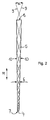
- einen Längsschnitt durch einen Lichtleiter, an dessen Lichteintrittsfläche eine Leuchtdiode angeordnet ist, wobei der Strahlengang in dem Lichtleiter durch Lichtstrahlen markiert ist,
- Fig.3
- eine perspektivische Seitenansicht des Lichtleiters, der eine gestufte Lichtaustritisfläche aufweist,
- Fig. 4
- eine Aufsicht auf ein Fahrzeug, wobei das Dach des Fahrzeugs durchsichtig dargestellt ist, um die Sicht auf die Fahrzeuginneneinrichtung freizugeben, und
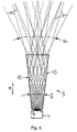
- Fig. 5
- einen Längsschnitt durch einen weiteren Lichtlelter, wobei der Strahlengang in dem Lichtleiter durch Lichtstrahlen markiert ist.
- Fig. 1
- 2 shows a partial view of a luminaire housing of an interior luminaire, partially shown in cross section, with a light guide arranged on the luminaire housing, which bundles the light from a light-emitting diode,
- Flg. 2
- 2 shows a longitudinal section through a light guide, on the light entry surface of which a light-emitting diode is arranged, the beam path in the light guide being marked by light beams,
- Figure 3
- 2 shows a perspective side view of the light guide, which has a stepped light austritis surface,
- Fig. 4
- a top view of a vehicle, the roof of the vehicle being shown transparently to expose the view of the vehicle interior, and
- Fig. 5
- a longitudinal section through a further light filter, the beam path in the light guide being marked by light beams.
Eine als Innenleuchte zur ambienten Beleuchtung eines Innenraums 1 eines
Fahrzeugs 2 ausgebildete Beleuchtungseinrichtung weist ein Trägerteil 3 auf (Fig. 1),
an dem ein Leuchtmittel 4 und ein diesem zugeordneter Lichtleiter 5 angeordnet
sind. Das Leuchtmittel 4 ist als Leuchtdiode ausgebildet, die auf einer in der Zeichnung
nicht näher dargestellten Leiterplatte montiert ist, die elektrische Anschlüsse
zum Verbinden mit einer Stromversorgung (Batterie) des Fahrzeugs 2 hat. Die
Leiterplatte ist an der in Gebrauchstellung dem Innenraum 1 des Fahrzeugs 2
abgewandten Rückseite des Trägerteils 3 angeordnet und an dort befindlichen
Befestigungsstellen mit diesem verbunden. Das Leuchtmittel 4 ist hinter einer
Öffnung 6 positioniert, die das Trägerteil 3 durchsetzt. In diese Öffnung 6 ist der
Lichtleiter 5 eingesetzt.One as an interior light for ambient lighting of an interior 1 of a
Lighting device designed for
Wie in Fig. 2 und 3 erkennbar ist, ist der Lichtleiter 5 stabförmig ausgebildet und hat
an seinem dem Leuchtmittel 4 zugewandten einen Ende eine Lichteintrittsfläche 7
und an seinem davon entfernten, dem Innenraum 1 zugewandten anderen Ende
eine Lichtaustrittsfläche 8. Die Normale auf die Mantelfläche des Lichtleiters 5 ist
derart relativ zu den in dem Lichtleiter 5 geführten Lichtstrahlen 9 angeordnet, dass
diese beim Auftreffen auf die Mantelfläche der Totalreflexion unterliegen.As can be seen in FIGS. 2 and 3, the
Der Lichtleiter 5 ist als Lichtsammeltell ausgebildet, welches das durch den Lichtleiter
5 hindurchtretende Licht derart bündelt, dass der Öffnungswinkel α des aus dem
Lichtleiter 5 ausgetretenen Lichtbündels kleiner ist als der Öffnungswinkel β des
Lichtbündels vor dem Eintritt in den Lichtleiter 5. Dies wird dadurch erreicht, dass an
dem Außenumfang des Lichtleiters 5 jeweils diametral einander gegenüberliegende
Seitenflächenbereiche 10 des Lichtleiters 5 derart schräg zueinander
verlaufen, dass sich der Querschnitt des Lichtleiters 5, ausgehend von der Lichteintrittsfläche
7 zu der Lichtaustrittsfläche 8, aufweltet. In orthogonal zur Längsmittelachse
des Lichtleiters 5 angeordneten Ebenen verlaufen die Seltenflächenbereiche 10
punktsymmetrisch zur Längsmittelachse des Lichtleiters 5. Wie bei dem Ausführungsbeispiel
nach Fig. 5 besonders gut erkennbar ist, reduziert sich der Winkel,
unter dem die Lichtstrahlen 9 zur Längserstreckungsrichtung Pf oder zur Längsmittelachse
des Lichtleiters 5 geneigt sind, bei der Reflexion der Lichtstrahlen 9 an den
Seitenflächenbereichen 10 jeweils um den doppelten, zwischen den einander
gegenüberliegenden Seitenflächenbereichen 10 eingeschlossenen Öffnungswinkel
δ des Lichtleiters 5. In Fig.5 ist weiter erkennbar, dass dieser Effekt bei den
Lichtstrahlen 9, die vor dem Eintritt in den Lichtleiter 5 stark gegen dessen Längserstreckungsrichtung
Pf geneigt sind, besonders effektiv ist, da diese Lichtstrahlen 9
mehrfach an den schräg zueinander verlaufenden Seitenflächenbereichen 10
reflektiert werden.The
Bei dem Ausführungsbeispiel nach Fig. 2 und 3 weist der Lichtleiter 5 mehrere, etwa
streifenförmig in Längserstreckungsrichtung Pf verlaufende, jeweils diametral
einander gegenüberliegende Seitenflächenbereiche 10 auf, die in Umfangsrichtung
des Lichtleiters 5 zueinander versetzt angeordnet sind. Dabei sind die jeweils
zwischen den diametral einander gegenüberliegenden Seitenflächenbereichen
10 eingeschlossenen Öffnungswinkel δ in Durchmesserebenen, die quer zueinander
verlaufen, unterschiedlich groß. Dies wird dadurch erreicht, dass sich der
Querschnltt des Lichtleiters 5 ausgehend von der Lichteintrittsfläche 7 zu der Lichtaustrittsfläche
8 von einem kreisförmigen Querschnitt in einen elliptischen Querschnitt
aufweitet, wobei der elliptische Querschnitt durch Streckung des kreisförmigen
Querschnitts gebildet ist. Dadurch ergibt sich in quer zueinander verlaufenden
Durchmesserrichtungen des Lichtleiters 5 eine unterschiedliche Lichtbündelung. Die
Richtung, in welcher der kreisförmige Querschnitt durch Streckung in den elliptischen
Querschnitt überführbar ist, ist in Gebrauchsstellung der innenleuchte quer
und insbesondere rechtwinklig zur Längsachse 12 des Fahrzeugs 2 bzw. zu dessen
Fahrtrichtung angeordnet. Die Innenleuchte strahlt dadurch ein ovales Lichtbündel
ab, dessen größte Querschnittsabmessung in Richtung der Längsachse 12 des
Fahrzeugs 2 orientiert ist.In the embodiment according to FIGS. 2 and 3, the
In Fig. 4 ist der mittels der Innenleuchte auf die Inneneinrichtung des Fahrzeugs 2
projizierte ovale Lichtfleck mit einer strichpunktierten Linie 13 markiert. Deutlich ist
erkennbar, dass die Lichtverteilung so gewählt ist, dass eine auf dem Fahrersitz 14
oder dem Beifahrersitz 15 sitzende Person durch das Licht der Innenleuchte nicht
angestrahlt oder geblendet wird. Die innenleuchte kann dadurch bei Nachtbetrieb
des Fahrzeugs auch während der Fahrt ständig eingeschaltet sein, um die zwischen
dem Fahrersitz 14 und dem Beifahrersitz 15 befindliche Inneneinrichtung, wie
z.B. eine Mittelkonsole, gleichförmig auszuleuchten. In Fig. 4 ist zum Vergleich mit
einer punktierten Linie 16 noch ein weiterer Lichtfleck bezeichnet, der sich bei einer
Innenleuchte mit rotationssymmetrischer Lichtabstrahlung ergeben würde.4 is the interior light of the
Bei dem Ausführungsbeispiel nach Fig. 5 weist der Lichtleiter 4 an seinem dem
Leuchtmittel 4 zugewandten Ende einen quadratischen Querschnitt auf, der sich zu
dem gegenüberliegenden, dem innenraum 5 zugewandten Ende des Lichtleiters 4
kontinuierlich zu einem quadratischen Querschnitt mit größeren Abmessungen
aufweitet. Der Lichtleiter 4 hat also die Form eines Obelisks. In entsprechender
Weise kann der Lichtleiter 4 auch andere eckige Grundformen aufweisen und
beispielsweise als Pyramidenstumpf ausgebildet sein. Als Leuchtmittel 4 ist bei dem
Ausführungsbeispiel nach Fig. 5 eine bereichsweise mit einem Leuchtstoff beschichtete
Elektrolumineszenzfolie vorgesehen.In the embodiment of FIG. 5, the
Bei dem Ausführungsbeispiel nach Fig. 3 weist die Lichtaustrittsfläche 8 mehrere
Schrägen 11 auf, die gegenüber einer orthogonal zur Längserstreckungsrichtung Pf
des Lichtleiters 5 angeordneten Ebene geneigt sind. Die Schrägen 11 sind jeweils
streifenförmig ausgebildet und mit ihrer Längserstreckung quer zu ihrer Neigungsrichtung
orientiert. Zueinander benachbart nebeneinander angeordnete Schrägen
11 sind mit ihren Erstreckungsebenen parallel zueinander orientiert. Dabei ist
zwischen diesen Schrägen 11 jeweils eine Stufe oder ein Absatz vorgesehen.3, the
Selbstverständlich sind auch andere Ausführungsformen denkbar, bei denen die
Schrägen 11 unter unterschiedlichen Winkeln gegenüber der orthogonal zur
Längserstreckungsrichtung Pf des Lichtleiters 4 angeordneten Ebene geneigt sein
können. Durch die schräg gestufte Lichtaustrittsfläche 8 wird das aus dem Lichtleiter
4 austretende Lichtbündel seitlich von der Längsmittelachse des Lichtleiters 5 weg
abgelenkt. In Gebrauchsstellung der Innenleuchte ist die Neigungsrichtung der
Schrägen 11 derart orientiert, dass das Lichtbündel von der Windschutzscheibe 17
des Fahrzeugs 2 in Richtung zur Fahrzeugmitte verschoben wird. Um dies zu
verdeutlichen ist in Fig. 4 mit der strichllnierten Linie 18 noch ein Lichtfleck markiert,
der sich bei einer Innenleuchte ergeben würde, bei der die Lichtaustrittsfläche
orthogonal zur Längserstreckungsrichtung Pf des Lichtleiters 5 angeordnet ist.Of course, other embodiments are also conceivable in which the
Somit ergibt sich eine Beleuchtungseinrichtung für ein Fahrzeug 2, insbesondere
Innenleuchte, die wenigstens ein Leuchtmittel 4 und mindestens ein diesem
zugeordnetes Lichtsammelteil hat. Das Lichtsammelteil ist als Lichtleiter 5 mit
wenigstens einer dem Leuchtmittel 4 zugewandten Lichteintrittsfläche 7 und
zumindest einer davon beabstandete Lichtaustrittsfläche 8 ausgebildet. Der
Lichtleiter 5 weist zwischen der Lichteintrittsfläche 7 und der Lichtaustrittsfläche 8
wenigstens zwei an seinem Außenumfang einander gegenüberliegend angeordnete
Seitenflächenbereiche 10 auf, an denen das in dem Lichtleiter 5 geführte Licht
der Totalreflexion unterliegt. Die Seitenflächenbereiche 10 verlaufen zum Bündeln
des Lichts derart schräg zueinander, dass sich der Querschnitt des Lichtleiters 5,
ausgehend von der Lichteintrittsfläche 7 zu der Lichtaustrittsfläche 8, aufweitet.This results in a lighting device for a
Claims (10)
Applications Claiming Priority (2)
| Application Number | Priority Date | Filing Date | Title |
|---|---|---|---|
| DE10231325A DE10231325A1 (en) | 2002-07-11 | 2002-07-11 | Lighting device for vehicles |
| DE10231325 | 2002-07-11 |
Publications (2)
| Publication Number | Publication Date |
|---|---|
| EP1380469A2 true EP1380469A2 (en) | 2004-01-14 |
| EP1380469A3 EP1380469A3 (en) | 2007-06-20 |
Family
ID=29723843
Family Applications (1)
| Application Number | Title | Priority Date | Filing Date |
|---|---|---|---|
| EP03102059A Withdrawn EP1380469A3 (en) | 2002-07-11 | 2003-07-09 | Lighting device for vehicles |
Country Status (2)
| Country | Link |
|---|---|
| EP (1) | EP1380469A3 (en) |
| DE (1) | DE10231325A1 (en) |
Cited By (10)
| Publication number | Priority date | Publication date | Assignee | Title |
|---|---|---|---|---|
| GB2412722A (en) * | 2004-03-31 | 2005-10-05 | Honda Access Kk | Interior illuminator for automobile |
| WO2008016326A1 (en) * | 2006-08-04 | 2008-02-07 | Optimal Lighting Partner Olp Ab | Illumination arrangement with light guide |
| EP1974389A2 (en) * | 2006-01-05 | 2008-10-01 | Illumitex, Inc. | Separate optical device for directing light from an led |
| DE102008039184A1 (en) * | 2008-08-20 | 2010-03-04 | Takata-Petri Ag | Method for manufacturing operating element for vehicle part, involves manufacturing operating element with lighting device |
| CN1676372B (en) * | 2004-03-31 | 2011-07-27 | 株式会社本田阿克塞斯 | Interior illuminator for automobile |
| US8087960B2 (en) | 2006-10-02 | 2012-01-03 | Illumitex, Inc. | LED system and method |
| US8115217B2 (en) | 2008-12-11 | 2012-02-14 | Illumitex, Inc. | Systems and methods for packaging light-emitting diode devices |
| US8263993B2 (en) | 2008-02-08 | 2012-09-11 | Illumitex, Inc. | System and method for emitter layer shaping |
| US8449128B2 (en) | 2009-08-20 | 2013-05-28 | Illumitex, Inc. | System and method for a lens and phosphor layer |
| US8585253B2 (en) | 2009-08-20 | 2013-11-19 | Illumitex, Inc. | System and method for color mixing lens array |
Families Citing this family (6)
| Publication number | Priority date | Publication date | Assignee | Title |
|---|---|---|---|---|
| DE102005042523A1 (en) | 2005-05-31 | 2006-12-07 | Osram Opto Semiconductors Gmbh | lighting device |
| DE102007054037A1 (en) | 2007-09-28 | 2009-04-02 | Osram Opto Semiconductors Gmbh | Lighting device, luminaire and display device |
| DE102010039859A1 (en) * | 2010-08-27 | 2012-03-01 | Osram Ag | Reading light for motor vehicles |
| DE102012211284A1 (en) | 2012-06-29 | 2014-01-02 | Automotive Lighting Reutlingen Gmbh | Light-guiding element for lighting device and light guide, has light entry surface for entry of light in light-guiding element and light exit surface spaced from light entry surface, by which light guided in light-guiding element is exit |
| DE102012106025A1 (en) * | 2012-07-05 | 2014-01-09 | Hella Kgaa Hueck & Co. | Illumination device for use in front region of vehicle for generating function of e.g. light, has luminous element designed as light source, where reflectors, lens and conductors are attached to element for generating light distribution |
| DE102019120751A1 (en) * | 2019-07-31 | 2021-02-04 | Automotive Lighting Reutlingen Gmbh | Light module for a motor vehicle |
Citations (5)
| Publication number | Priority date | Publication date | Assignee | Title |
|---|---|---|---|---|
| EP0534853A1 (en) * | 1991-09-25 | 1993-03-31 | Marc Hoffman | Double refraction and total reflection solid non-imaging lens |
| WO1999020937A1 (en) * | 1997-10-16 | 1999-04-29 | Advanced Optical Technologies, Llc | Directed lighting system utilizing a conical light deflector |
| US6164805A (en) * | 1998-04-20 | 2000-12-26 | Federal-Mogul World Wide, Inc. | Illuminated door handle for a vehicle |
| EP1083090A2 (en) * | 1999-09-11 | 2001-03-14 | Preh-Werke GmbH & Co. KG | Light conductor with a mushroom form |
| GB2365962A (en) * | 2000-08-01 | 2002-02-27 | Visteon Global Tech Inc | Collimating lamp with light pipes |
Family Cites Families (5)
| Publication number | Priority date | Publication date | Assignee | Title |
|---|---|---|---|---|
| DE19621148A1 (en) * | 1996-05-14 | 1997-12-04 | Magna Reflex Holding Gmbh | Lighting element, especially e.g. for use in motor vehicles |
| DE10036812A1 (en) * | 2000-07-28 | 2002-02-07 | Hella Kg Hueck & Co | Conformable interior light for car based on electroluminescent foil source, comprises edge-lit planar optical conductor guiding light by total internal reflection |
| DE20019073U1 (en) * | 2000-11-09 | 2001-02-22 | Hella Kg Hueck & Co | Lighting device |
| DE20113287U1 (en) * | 2001-08-09 | 2002-01-03 | Hella Kg Hueck & Co | Lighting device for vehicles |
| JP3426226B1 (en) * | 2002-01-10 | 2003-07-14 | 日本ライツ株式会社 | Light guide member, lighting unit and instrument |
-
2002
- 2002-07-11 DE DE10231325A patent/DE10231325A1/en not_active Withdrawn
-
2003
- 2003-07-09 EP EP03102059A patent/EP1380469A3/en not_active Withdrawn
Patent Citations (5)
| Publication number | Priority date | Publication date | Assignee | Title |
|---|---|---|---|---|
| EP0534853A1 (en) * | 1991-09-25 | 1993-03-31 | Marc Hoffman | Double refraction and total reflection solid non-imaging lens |
| WO1999020937A1 (en) * | 1997-10-16 | 1999-04-29 | Advanced Optical Technologies, Llc | Directed lighting system utilizing a conical light deflector |
| US6164805A (en) * | 1998-04-20 | 2000-12-26 | Federal-Mogul World Wide, Inc. | Illuminated door handle for a vehicle |
| EP1083090A2 (en) * | 1999-09-11 | 2001-03-14 | Preh-Werke GmbH & Co. KG | Light conductor with a mushroom form |
| GB2365962A (en) * | 2000-08-01 | 2002-02-27 | Visteon Global Tech Inc | Collimating lamp with light pipes |
Cited By (17)
| Publication number | Priority date | Publication date | Assignee | Title |
|---|---|---|---|---|
| GB2412722A (en) * | 2004-03-31 | 2005-10-05 | Honda Access Kk | Interior illuminator for automobile |
| GB2412722B (en) * | 2004-03-31 | 2007-09-19 | Honda Access Kk | Interior illuminator for automobile |
| US7287886B2 (en) | 2004-03-31 | 2007-10-30 | Honda Access Corp. | Interior illuminator for automobile |
| CN1676372B (en) * | 2004-03-31 | 2011-07-27 | 株式会社本田阿克塞斯 | Interior illuminator for automobile |
| EP1974389A2 (en) * | 2006-01-05 | 2008-10-01 | Illumitex, Inc. | Separate optical device for directing light from an led |
| EP1974389A4 (en) * | 2006-01-05 | 2010-12-29 | Illumitex Inc | Separate optical device for directing light from an led |
| US7968896B2 (en) | 2006-01-05 | 2011-06-28 | Illumitex, Inc. | Separate optical device for directing light from an LED |
| US8896003B2 (en) | 2006-01-05 | 2014-11-25 | Illumitex, Inc. | Separate optical device for directing light from an LED |
| US9574743B2 (en) | 2006-01-05 | 2017-02-21 | Illumitex, Inc. | Separate optical device for directing light from an LED |
| WO2008016326A1 (en) * | 2006-08-04 | 2008-02-07 | Optimal Lighting Partner Olp Ab | Illumination arrangement with light guide |
| US8087960B2 (en) | 2006-10-02 | 2012-01-03 | Illumitex, Inc. | LED system and method |
| US8263993B2 (en) | 2008-02-08 | 2012-09-11 | Illumitex, Inc. | System and method for emitter layer shaping |
| DE102008039184A1 (en) * | 2008-08-20 | 2010-03-04 | Takata-Petri Ag | Method for manufacturing operating element for vehicle part, involves manufacturing operating element with lighting device |
| US8115217B2 (en) | 2008-12-11 | 2012-02-14 | Illumitex, Inc. | Systems and methods for packaging light-emitting diode devices |
| US8449128B2 (en) | 2009-08-20 | 2013-05-28 | Illumitex, Inc. | System and method for a lens and phosphor layer |
| US8585253B2 (en) | 2009-08-20 | 2013-11-19 | Illumitex, Inc. | System and method for color mixing lens array |
| US9086211B2 (en) | 2009-08-20 | 2015-07-21 | Illumitex, Inc. | System and method for color mixing lens array |
Also Published As
| Publication number | Publication date |
|---|---|
| DE10231325A1 (en) | 2004-02-12 |
| EP1380469A3 (en) | 2007-06-20 |
Similar Documents
| Publication | Publication Date | Title |
|---|---|---|
| EP2851718B1 (en) | Illumination device of a motor vehicle | |
| DE4040020C2 (en) | Lighting device for vehicles | |
| DE102006044019B4 (en) | reflector spotlight | |
| EP2607774B1 (en) | Motor vehicle lighting device with a long and flat luminescent area | |
| DE102004020708B4 (en) | Projector optics group for formation and projection of a directional characteristic with high gradient for vehicles | |
| EP1380469A2 (en) | Lighting device for vehicles | |
| EP1744096B1 (en) | Vehicle light | |
| DE102006037797B4 (en) | Motor vehicle light | |
| DE102011085314B3 (en) | Light module for illumination device e.g. headlight of motor car, has primary optics having one lens element that is formed by translation of ellipse portion and light exit surface of another lens element in sectional plane | |
| DE10022420A1 (en) | Lighting device. esp. lamp for motor vehicle, uses at least one light-emitting element radiating light to generate an illuminance partition | |
| DE10311072A1 (en) | Vehicle light with LED light sources | |
| DE10231326A1 (en) | Light unit for automobile e.g. automobile headlamp, has spaced light source elements associated with light conduction elements positioned behind light disc | |
| DE10139578A1 (en) | Interior light for vehicle, has light sources with different spectral distributions whose light is divergently coupled in transition region to light conductor strand and mixed together | |
| EP1642064A1 (en) | Light for a vehicle | |
| EP3210827A1 (en) | Vehicle lamp | |
| DE10356483B4 (en) | Vehicle outside mirror light of a motor vehicle | |
| DE102009005351A1 (en) | Light e.g. tail light, for providing stop/turn/tail light function in motor vehicle, has two sets of light deflectors associated with light guides for directing light, where one of sets of deflectors is offset from other set of deflectors | |
| DE202005010490U1 (en) | Optical body made from a light permeable material for vehicle headlamps comprises a base part having a V-shaped outer contour with a recess for receiving a light source | |
| EP1610157A1 (en) | Lighting assembly for a vehicle comrpising a linear light guide | |
| DE19857561A1 (en) | Vehicle light includes light guide rod, luminous diodes, and light inlet surface and opposite end surface formed as light deflecting region | |
| DE102011051541B4 (en) | Lighting device for vehicles | |
| DE102011004349A1 (en) | Lighting device of a motor vehicle | |
| DE10259236A1 (en) | Automobile interior light with different light sources for different lighting functions e.g. interior illumination and ambient lighting | |
| DE19930461A1 (en) | Vehicle light has lenses that convert conical light radiation pattern from light emitting diode(s) into light beam with elliptical or strip-shaped cross-section then into parallel beam | |
| DE102017106441A1 (en) | Motor vehicle light with a planar light guide |
Legal Events
| Date | Code | Title | Description |
|---|---|---|---|
| PUAI | Public reference made under article 153(3) epc to a published international application that has entered the european phase |
Free format text: ORIGINAL CODE: 0009012 |
|
| AK | Designated contracting states |
Kind code of ref document: A2 Designated state(s): AT BE BG CH CY CZ DE DK EE ES FI FR GB GR HU IE IT LI LU MC NL PT RO SE SI SK TR |
|
| AX | Request for extension of the european patent |
Extension state: AL LT LV MK |
|
| RAP1 | Party data changed (applicant data changed or rights of an application transferred) |
Owner name: HELLA KGAA HUECK & CO. |
|
| PUAL | Search report despatched |
Free format text: ORIGINAL CODE: 0009013 |
|
| AK | Designated contracting states |
Kind code of ref document: A3 Designated state(s): AT BE BG CH CY CZ DE DK EE ES FI FR GB GR HU IE IT LI LU MC NL PT RO SE SI SK TR |
|
| AX | Request for extension of the european patent |
Extension state: AL LT LV MK |
|
| RIC1 | Information provided on ipc code assigned before grant |
Ipc: B60Q 3/02 20060101ALI20070515BHEP Ipc: G02B 6/00 20060101AFI20070515BHEP |
|
| 17P | Request for examination filed |
Effective date: 20071213 |
|
| 17Q | First examination report despatched |
Effective date: 20080123 |
|
| AKX | Designation fees paid |
Designated state(s): AT BE BG CH CY CZ DE DK EE ES FI FR GB GR HU IE IT LI LU MC NL PT RO SE SI SK TR |
|
| STAA | Information on the status of an ep patent application or granted ep patent |
Free format text: STATUS: THE APPLICATION IS DEEMED TO BE WITHDRAWN |
|
| 18D | Application deemed to be withdrawn |
Effective date: 20080603 |