EP1391693A1 - Fiber optic sensors with reduced noise - Google Patents
Fiber optic sensors with reduced noise Download PDFInfo
- Publication number
- EP1391693A1 EP1391693A1 EP03255149A EP03255149A EP1391693A1 EP 1391693 A1 EP1391693 A1 EP 1391693A1 EP 03255149 A EP03255149 A EP 03255149A EP 03255149 A EP03255149 A EP 03255149A EP 1391693 A1 EP1391693 A1 EP 1391693A1
- Authority
- EP
- European Patent Office
- Prior art keywords
- optical
- port
- hollow
- light
- light source
- Prior art date
- Legal status (The legal status is an assumption and is not a legal conclusion. Google has not performed a legal analysis and makes no representation as to the accuracy of the status listed.)
- Granted
Links
- 239000000835 fiber Substances 0.000 title claims abstract description 227
- 230000002829 reductive effect Effects 0.000 title description 26
- 230000001902 propagating effect Effects 0.000 claims abstract description 20
- 239000004065 semiconductor Substances 0.000 claims abstract description 3
- 230000003287 optical effect Effects 0.000 claims description 172
- 238000000034 method Methods 0.000 claims description 43
- VYPSYNLAJGMNEJ-UHFFFAOYSA-N Silicium dioxide Chemical compound O=[Si]=O VYPSYNLAJGMNEJ-UHFFFAOYSA-N 0.000 claims description 35
- 238000005253 cladding Methods 0.000 claims description 32
- 239000000377 silicon dioxide Substances 0.000 claims description 17
- 230000003595 spectral effect Effects 0.000 claims description 14
- 238000009826 distribution Methods 0.000 claims description 6
- 239000011521 glass Substances 0.000 claims description 5
- 230000000737 periodic effect Effects 0.000 claims description 3
- 230000002452 interceptive effect Effects 0.000 claims 2
- 239000013307 optical fiber Substances 0.000 abstract description 42
- 230000005374 Kerr effect Effects 0.000 abstract description 22
- 230000010363 phase shift Effects 0.000 abstract description 10
- 239000007787 solid Substances 0.000 description 27
- 230000000694 effects Effects 0.000 description 21
- 230000010287 polarization Effects 0.000 description 21
- 230000001427 coherent effect Effects 0.000 description 19
- 238000013461 design Methods 0.000 description 12
- 238000010168 coupling process Methods 0.000 description 11
- 230000008878 coupling Effects 0.000 description 10
- 238000005859 coupling reaction Methods 0.000 description 10
- 239000007789 gas Substances 0.000 description 9
- 239000000463 material Substances 0.000 description 9
- 238000004458 analytical method Methods 0.000 description 5
- 230000008901 benefit Effects 0.000 description 5
- 230000009467 reduction Effects 0.000 description 5
- 230000003247 decreasing effect Effects 0.000 description 4
- 238000005516 engineering process Methods 0.000 description 4
- 230000008859 change Effects 0.000 description 3
- 230000007547 defect Effects 0.000 description 3
- 230000037361 pathway Effects 0.000 description 3
- 239000004038 photonic crystal Substances 0.000 description 3
- 230000005855 radiation Effects 0.000 description 3
- 230000035945 sensitivity Effects 0.000 description 3
- 238000003491 array Methods 0.000 description 2
- 230000001627 detrimental effect Effects 0.000 description 2
- 230000005684 electric field Effects 0.000 description 2
- 239000002657 fibrous material Substances 0.000 description 2
- 230000005426 magnetic field effect Effects 0.000 description 2
- 238000004519 manufacturing process Methods 0.000 description 2
- 239000011159 matrix material Substances 0.000 description 2
- 230000036961 partial effect Effects 0.000 description 2
- 238000012545 processing Methods 0.000 description 2
- 239000000126 substance Substances 0.000 description 2
- 241000700159 Rattus Species 0.000 description 1
- -1 and where n2 Substances 0.000 description 1
- 230000002238 attenuated effect Effects 0.000 description 1
- 230000009286 beneficial effect Effects 0.000 description 1
- 238000004891 communication Methods 0.000 description 1
- 230000001419 dependent effect Effects 0.000 description 1
- 238000001514 detection method Methods 0.000 description 1
- 238000011161 development Methods 0.000 description 1
- 239000006185 dispersion Substances 0.000 description 1
- 230000008030 elimination Effects 0.000 description 1
- 238000003379 elimination reaction Methods 0.000 description 1
- 238000004880 explosion Methods 0.000 description 1
- 238000000605 extraction Methods 0.000 description 1
- 239000005350 fused silica glass Substances 0.000 description 1
- 230000036039 immunity Effects 0.000 description 1
- 238000010348 incorporation Methods 0.000 description 1
- 230000000670 limiting effect Effects 0.000 description 1
- 230000007774 longterm Effects 0.000 description 1
- 238000005259 measurement Methods 0.000 description 1
- 229910000595 mu-metal Inorganic materials 0.000 description 1
- 230000003534 oscillatory effect Effects 0.000 description 1
- 239000002245 particle Substances 0.000 description 1
- 230000000644 propagated effect Effects 0.000 description 1
- 238000005510 radiation hardening Methods 0.000 description 1
- 229910052761 rare earth metal Inorganic materials 0.000 description 1
- 150000002910 rare earth metals Chemical class 0.000 description 1
- 238000005245 sintering Methods 0.000 description 1
- 239000011343 solid material Substances 0.000 description 1
- 230000001360 synchronised effect Effects 0.000 description 1
Images


Classifications
-
- G—PHYSICS
- G01—MEASURING; TESTING
- G01D—MEASURING NOT SPECIALLY ADAPTED FOR A SPECIFIC VARIABLE; ARRANGEMENTS FOR MEASURING TWO OR MORE VARIABLES NOT COVERED IN A SINGLE OTHER SUBCLASS; TARIFF METERING APPARATUS; MEASURING OR TESTING NOT OTHERWISE PROVIDED FOR
- G01D5/00—Mechanical means for transferring the output of a sensing member; Means for converting the output of a sensing member to another variable where the form or nature of the sensing member does not constrain the means for converting; Transducers not specially adapted for a specific variable
- G01D5/26—Mechanical means for transferring the output of a sensing member; Means for converting the output of a sensing member to another variable where the form or nature of the sensing member does not constrain the means for converting; Transducers not specially adapted for a specific variable characterised by optical transfer means, i.e. using infrared, visible, or ultraviolet light
- G01D5/32—Mechanical means for transferring the output of a sensing member; Means for converting the output of a sensing member to another variable where the form or nature of the sensing member does not constrain the means for converting; Transducers not specially adapted for a specific variable characterised by optical transfer means, i.e. using infrared, visible, or ultraviolet light with attenuation or whole or partial obturation of beams of light
- G01D5/34—Mechanical means for transferring the output of a sensing member; Means for converting the output of a sensing member to another variable where the form or nature of the sensing member does not constrain the means for converting; Transducers not specially adapted for a specific variable characterised by optical transfer means, i.e. using infrared, visible, or ultraviolet light with attenuation or whole or partial obturation of beams of light the beams of light being detected by photocells
- G01D5/353—Mechanical means for transferring the output of a sensing member; Means for converting the output of a sensing member to another variable where the form or nature of the sensing member does not constrain the means for converting; Transducers not specially adapted for a specific variable characterised by optical transfer means, i.e. using infrared, visible, or ultraviolet light with attenuation or whole or partial obturation of beams of light the beams of light being detected by photocells influencing the transmission properties of an optical fibre
- G01D5/3537—Optical fibre sensor using a particular arrangement of the optical fibre itself
- G01D5/3538—Optical fibre sensor using a particular arrangement of the optical fibre itself using a particular type of fiber, e.g. fibre with several cores, PANDA fiber, fiber with an elliptic core or the like
-
- G—PHYSICS
- G01—MEASURING; TESTING
- G01C—MEASURING DISTANCES, LEVELS OR BEARINGS; SURVEYING; NAVIGATION; GYROSCOPIC INSTRUMENTS; PHOTOGRAMMETRY OR VIDEOGRAMMETRY
- G01C19/00—Gyroscopes; Turn-sensitive devices using vibrating masses; Turn-sensitive devices without moving masses; Measuring angular rate using gyroscopic effects
- G01C19/58—Turn-sensitive devices without moving masses
- G01C19/64—Gyrometers using the Sagnac effect, i.e. rotation-induced shifts between counter-rotating electromagnetic beams
- G01C19/72—Gyrometers using the Sagnac effect, i.e. rotation-induced shifts between counter-rotating electromagnetic beams with counter-rotating light beams in a passive ring, e.g. fibre laser gyrometers
- G01C19/721—Details
- G01C19/722—Details of the mechanical construction
-
- G—PHYSICS
- G01—MEASURING; TESTING
- G01D—MEASURING NOT SPECIALLY ADAPTED FOR A SPECIFIC VARIABLE; ARRANGEMENTS FOR MEASURING TWO OR MORE VARIABLES NOT COVERED IN A SINGLE OTHER SUBCLASS; TARIFF METERING APPARATUS; MEASURING OR TESTING NOT OTHERWISE PROVIDED FOR
- G01D5/00—Mechanical means for transferring the output of a sensing member; Means for converting the output of a sensing member to another variable where the form or nature of the sensing member does not constrain the means for converting; Transducers not specially adapted for a specific variable
- G01D5/26—Mechanical means for transferring the output of a sensing member; Means for converting the output of a sensing member to another variable where the form or nature of the sensing member does not constrain the means for converting; Transducers not specially adapted for a specific variable characterised by optical transfer means, i.e. using infrared, visible, or ultraviolet light
- G01D5/32—Mechanical means for transferring the output of a sensing member; Means for converting the output of a sensing member to another variable where the form or nature of the sensing member does not constrain the means for converting; Transducers not specially adapted for a specific variable characterised by optical transfer means, i.e. using infrared, visible, or ultraviolet light with attenuation or whole or partial obturation of beams of light
- G01D5/34—Mechanical means for transferring the output of a sensing member; Means for converting the output of a sensing member to another variable where the form or nature of the sensing member does not constrain the means for converting; Transducers not specially adapted for a specific variable characterised by optical transfer means, i.e. using infrared, visible, or ultraviolet light with attenuation or whole or partial obturation of beams of light the beams of light being detected by photocells
- G01D5/353—Mechanical means for transferring the output of a sensing member; Means for converting the output of a sensing member to another variable where the form or nature of the sensing member does not constrain the means for converting; Transducers not specially adapted for a specific variable characterised by optical transfer means, i.e. using infrared, visible, or ultraviolet light with attenuation or whole or partial obturation of beams of light the beams of light being detected by photocells influencing the transmission properties of an optical fibre
- G01D5/35306—Mechanical means for transferring the output of a sensing member; Means for converting the output of a sensing member to another variable where the form or nature of the sensing member does not constrain the means for converting; Transducers not specially adapted for a specific variable characterised by optical transfer means, i.e. using infrared, visible, or ultraviolet light with attenuation or whole or partial obturation of beams of light the beams of light being detected by photocells influencing the transmission properties of an optical fibre using an interferometer arrangement
- G01D5/35322—Mechanical means for transferring the output of a sensing member; Means for converting the output of a sensing member to another variable where the form or nature of the sensing member does not constrain the means for converting; Transducers not specially adapted for a specific variable characterised by optical transfer means, i.e. using infrared, visible, or ultraviolet light with attenuation or whole or partial obturation of beams of light the beams of light being detected by photocells influencing the transmission properties of an optical fibre using an interferometer arrangement using interferometer with one loop with several directions of circulation of the light, e.g. Sagnac interferometer
-
- H—ELECTRICITY
- H01—ELECTRIC ELEMENTS
- H01S—DEVICES USING THE PROCESS OF LIGHT AMPLIFICATION BY STIMULATED EMISSION OF RADIATION [LASER] TO AMPLIFY OR GENERATE LIGHT; DEVICES USING STIMULATED EMISSION OF ELECTROMAGNETIC RADIATION IN WAVE RANGES OTHER THAN OPTICAL
- H01S3/00—Lasers, i.e. devices using stimulated emission of electromagnetic radiation in the infrared, visible or ultraviolet wave range
- H01S3/05—Construction or shape of optical resonators; Accommodation of active medium therein; Shape of active medium
- H01S3/06—Construction or shape of active medium
- H01S3/063—Waveguide lasers, i.e. whereby the dimensions of the waveguide are of the order of the light wavelength
- H01S3/067—Fibre lasers
Definitions
- the present invention relates to fiber optic interferometers, and more particularly, relates to fiber optic Sagnac interferometers for sensing, For example, rotation, movement, pressure, or other stimuli.
- a fiber optic Sagnac interferometer typically comprises a loop of optical fiber to which lightwaves are coupled for propagation around the loop in opposite directions. After traversing the loop, the counterpropagating waves are combined so that they coherently interfere to form an optical output signal. The intensity of this optical output signal varies as a function of the relative phase of the counterpropagating waves when the waves are combined.
- Sagnac interferometers have proven particularly useful for rotation sensing. Rotation of the loop about the loop's central axis of symmetry creates a relative phase difference between the counterpropagating waves in accordance with the well-known Sagnac effect, with the amount of phase difference proportional to the loop rotation rats.
- the optical output signal produced by the interference of the combined counterpropagating waves varies in power as a function of the rotation rate of the loop. Rotation sensing is accomplished by detection of this optical output signal.
- Rotation sensing accuracies of Sagnac interferometers are limited by spurious waves caused by Rayleigh backscattering.
- Rayleigh scattering occurs in present state-of-the-art optical fibers because the small elemental particles that make up the fiber material cause scattering of small amounts of light.
- light is scattered in all directions, Light that is scattered forward and within the acceptance angle of the fiber is the forward-scattered light.
- Light that is scattered backward and within the acceptance angle of the fiber is the back-scattered light.
- a fiber-optic gyroscope both the clockwise and the counterclockwise waves along the sensing coil (referred to here as the primary clockwise and primary counterclockwise waves) are scattered by Rayleigh scattering.
- the primary clockwise wave and the primary counterclockwise wave are both scattered in respective forward and backward directions.
- This scattered light returns to the detector and adds noise to the primary clockwise wave and to the secondary counterclockwise wave.
- the scattered light is divided into two types, coherent and incoherent.
- Coherently scattered light originates from scattering occurring along the section of fiber of length L c centered around the mid-point of the coil, where L c is the coherence length of the light source.
- This scattered light is coherent with the primary wave from which it is derived and interferes coherently with the primary wave.
- a sizeable amount of phase noise is produced.
- Forward coherent scattering is in phase with the primary wave from which it is scattered, so it does not add phase noise. Instead, this forward coherent scattering adds shot noise.
- the scattered power is so small compared to the primary wave power that this shot noise is negligible. All other portions of the coil produce scattered light that is incoherent with the primary waves. The forward propagating incoherent scattered light adds only shot noise to the respective primary wave from which it originates, and this shot noise is also negligible.
- the dominant scattered noise is coherent backscattering. This coherent backscattering noise can be large.
- the coherent backscattering noise has been reduced historically by using a broadband source, which has a very short coherence length L c .
- the potion of backscattering wave originates from a very small section of fiber, namely a length L c of typically a few tens of microns centered on the mid-point of the fiber coil, and it is thus dramatically reduced compared to what it would be with a traditional narrowband laser, which has a coherence length upward of many meters. See for example, Hervé LefJacques. The Fiber-Optic Gyroscope, Section 4.2, Artech House, Boston, London, 1993, and references cited therein.
- Rotation sensing accuracies are also limited by the AC Kerr effect, which cause phase differences between counterpropagating waves in the interferometers.
- the AC Kerr effect is a well-known nonlinear optical phenomena in which the refractive index of a substance changes when the substance is placed in a varying electric field.
- the electric fields of lightwaves propagating in the optical fiber can change the refractive index of the fiber in accordance with the Kerr effect, Since the propagation constant of each of the waves traveling in tile fiber is a function of rafractive index, the Kerr effect manifests itself as intensity dependent perturbations of the propagation constants.
- the optical Kerr effect will generally cause the waves to propagate with different velocities, resulting in a non-rotationally-induced phase difference between the waves, and thereby creating a spurious signal. See, for example, pages 101-106 of the above-cited Hervé Lefberg, The Fiber Optic Gyroscope, and references cited therein.
- the spurious signal is indistinguishable from a rotationally induced signal.
- Fused silica optical fibers exhibit sufficiently strong Kerr nonlinearity that for the typical level of optical power traveling in a fiber optic gyroscope coil, the Kerr-induced phase difference in the fiber optic rotation sensor may be much larger than the phase difference due to the Sagnac effect at small rotation rates.
- Silica in silica-based fibers also can be affected by magnetic fields.
- silica exhibits magneto-optic properties.
- a longitudinal magnetic field of magnitude B modifies the phase of a circularly polarized wave by an amount proportional to B .
- the change in phase of the circularly polarized wave is also proportional to the Verdet constant V of the fiber material and the length of fiber L over which the field is applied.
- the sign of the phase shift depends on whether the light is left-hand or right-hand circularly polarized, The sign also depends on the relative direction of the magnetic field and the light propagation.
- This effect is non-reciprocal.
- the magneto-optic Faraday effect induces a phase difference equal to 2 ⁇ between the counterpropagating waves. If a magnetic field is applied to a fiber coil, however, the clockwise and counterclockwise waves will in general experience a slightly different phase shift. The result is a magnetic-field-induced relative phase shift between the clockwise and countercloclcwise propagating waves at the output of the fiber optic loop where the waves interfere.
- This differential phase shift is proportional to the Verdet constant. This phase difference also depends on the magnitude of the magnetic field and the birefringence of the fiber in the loop. Additionally, the phase shift depends on the orientation (i.e., the direction) of the magnetic field with respect to the fiber optic loop as well as on the polarizations of the clockwise and counterclockwise propagating signals. If the magnetic field is DC, this differential phase shift results in a DC offset in the phase bias of the Sagnac interferometer, If the magnetic field varies over time, this phase bias drifts, which is generally undesirable and thus not preferred.
- the earth's magnetic field poses particular difficulty for Sagnac interferometers employed in navigation.
- the relative spatial orientation of the fiber optic loop changes with respect to the magnetic field of the earth.
- the phase bias of the output of the fiber gyroscope drifts.
- This magnetic held-induced drift can be substantial when the fiber optic loop is sufficiently long, e.g., about 1000 meters.
- the fiber optic loop may be shielded from external magnetic fields Shielding comprising a plurality of layers of ⁇ -metal may be utilized,
- hollow-core photonic-bandgap optical fiber is incorporated in Sagnac interferometers, for example, to improve performance or to provide other design alternatives.
- One aspect of the invention comprises a sensor that includes a light source, a directional coupler, a hollow-core photonic-bandgap optical fiber, and an optical detector.
- the light source has an output that emits a first optical signal.
- the directional coupler comprises a plurality of ports. A first port is optically coupled to the light source to receive the first optical signal emitted from the light source. The first port is optically coupled to a second port and to a third port such that the first optical signal coupled into the first port is split into a second optical signal and a third optical signal that are output by the second port and the third port, respectively.
- the hollow-core photonic-bandgap optical fiber is optically coupled to the second port and to the third port such that the second optical signal and the third optical signal output from the second port and the third port counterpropagate through the hollow-core photonic-bandgap optical fiber and return to the third port and to the second optical port, respectively.
- the hollow-core photonic-bandgap optical fiber has a hollow optical core surrounded by a cladding.
- the cladding of the hollow-core photonic-bandgap optical fiber substantially confines the counterpropagating second and third optical signals within the hollow optical core.
- the optical detector is located at a position in the optical instrument to receive the counterpropagating second and third optical signals after having traversed the hollow-core photonic-bandgap optical fiber.
- the light source comprises a broadband light source outputting light having a spectral wavelength distribution of about 1 nanometer or larger in bandwidth as measured as the full width at half maximum (FWHM).
- the light source comprises a narrowband source outputting light baying a spectral wavelength distribution less than 1 nanometer in bandwidth.
- the spectral wavelength distribution of the light from the narrowband source as measured as the FWHM is less than 0,5 nanometer. More preferably, the spectral. FWHM bandwidth of the light from the narrowband source is less than 0.1 nanometer.
- Another aspect of the invention comprises a method of sensing,
- light is produced that has a mean wavelength, ⁇ .
- the light is divided into a first portion and a second portion.
- the first portion propagates clockwise around a hollow waveguide, and the second portion propagates counterclockwise around the hollow waveguide.
- the first portion and the second portion are substantially confined to propagate through a hollow core in the hollow waveguide by a surrounding cladding having a photonic-bandgap structure for the light of wavelength, ⁇ .
- the first and second portions of the light are optically interfered after propagating around the hollow waveguide in the respective clockwise and counterclockwise directions, thereby producing an optical interference signal.
- the hollow waveguide is subject to a perturbation, and variations in the optical interference signal caused by the perturbation are measured.
- the perturbation may comprise, for example, rotation, movement, pressure, or other stimuli.
- the light is confined to the hollow core that is evacuated or that includes air or other gases.
- the light is modulated in amplitude at a duty cycle between about 45% and 55%, More preferably, the light is amplitude modulated at a duty cycle of about 50%,
- Another aspect of the invention comprises a sensor that includes a light source, a directional coupler, a hollow-core photonic-bandgap fiber, and an optical detector.
- the light source has an output that emits a first optical signal having a mean wavelength, ⁇ , stable to within at least about ⁇ 10 -6 (e.g., stable to one part per million).
- the directional coupler comprises a plurality of ports. A first port is optically coupled to the light source to receive the first optical signal emitted from the light source. The first port is also optically coupled to a second port and to a third port such that the first optical signal coupled into the first port is split into a second optical signal and a third optical signal that are output by the second port and the third port, respectively.
- the photonic-bandgap fiber has a hollow core surrounded by a cladding.
- the hollow-core photonic-bandgap fiber is optically coupled to the second port and to the third port such that the second optical signal and the third optical signal output from the second port and the third port counterpropagate through the hollow-core photonic-bandgap fiber and return to the third port and to the second optical port, respectively.
- the cladding of the hollow-core photonic-bandgap fiber substantially contains the counterpropagating second and third optical signals within the hollow core.
- the optical detector is located at a position in the optical instrument to receive the counterpropagating second and third optical signals after having traversed the hollow-core photonic-bandgap fiber.
- Another aspect of the invention comprises another method for sensing.
- light is produced having a substantially invariant mean wavelength, ⁇ , which varies no more than about ⁇ 10 -6 (e.g., one part per million),
- ⁇ substantially invariant mean wavelength
- a first portion of the light propagates clockwise around an optical path
- a second portion of the light propagates counterclockwise around the optical path.
- the first and second portions of light are substantially confined to propagation through the optical path by a photonic-bandgap structure for light at the wavelength, ⁇ .
- the first and second portions of light are optically interfered after both portions have propagated around the optical path in the respcetive clockwise and counterclockwise directions, thereby producing an optical interference signal.
- At least a portion of the optical path is subject to a perturbation.
- the optical interference signal caused by the perturbation may comprise rotation, pressure, movement, or other stimuli.
- the light is confined to an open region that is evacuated or that includes air or other gases.
- the light that is divided into two portions is amplitude modulated at a duty cycle between about 45%. and 55%, and more preferably, at a duty cycle of between about 49% and about 51%, and most preferably at a duty cycle of 50%.
- the light that is divided into two portion is frequency modulated at a Frequency between about 1 GHz and about 50 GHz, and more preferably, is modulated at a frequency of about 10 GHz.
- Figure 1 is a schematic drawing of an exemplary Sagnac interferometer depicting the light source, the fiber loop, and the optical detector;
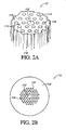
- Figure 2A is a partial perspective view of the core and a portion of the surrounding cladding of a hollow-core photonic-bandgap fiber that can be used in the exemplary Sagnac interferometer;
- Figure 2B is a cross-sectional view of the hollow-core photonic-bandgap fiber showing more of the features in the cladding arranged in a pattern around the hollow core;
- Figure 3 is a schematic drawing of an exemplary Sagnac interferometer wherein the light source comprises a narrowband light source;
- Figure 4 is a schematic drawing of an exemplary Sagnac interferometer driven by a narrowband light source with a modulator for modulating the amplitude of the narrowband light source;
- Figure 5 is a schematic drawing of an exemplary Sagnac interferometer wherein the light source comprises a broadband light source;
- Figure 6 is a schematic drawing of an exemplary Sagnac interferometer driven by a broadband light source with a modulator for modulating the amplitude of the broadband light source.
- Figure 1 illustrates an exemplary Sagnac interferometer 5 that comprises a fiber optic system 12 that incorporates a photonic-bandgap fiber 13, which, in the preferred embodiments, is a hollow-core photonic-bandgap fiber.
- a fiber optic system 12 that incorporates a photonic-bandgap fiber 13 which, in the preferred embodiments, is a hollow-core photonic-bandgap fiber.
- a version of a similar fiber optic system that includes a conventional optical fiber father than a photonic-bandgap fiber is more fully described in U.S. Patent No. 4,773,759 to Bergh et al., issued on September 27, 1988, which is hereby incorporated herein by reference in its entirety.
- the fiber optic system 12 includes various components positioned at various locations along the fiber optic system 12 for guiding and processing the light. Such components and their use in a Sagnac interferometer 5 are well-known. Alternative embodiments of the system 12 having similar designs or different designs may be realized by those skilled in the art and used in embodiments of the invention.
- the fiber optic system 12 includes a light source 16, a fiber optic loop 14 formed with the hollow-core photonic-bandgap fiber 13 (described below in connection with Figures 2A and 2B), and a photodetector 30.
- the wavelength of the light output from the light source 16 may be approximately 1.50 to 1.58 microns, in a spectral region where the loss of silica-based optical fibers is near its minimum. Other wavelengths, however, are possible, and the wavelength of the source emission is not limited to the wavelengths recited herein.
- the optical fiber comprises a material other than silica
- the wavelength is preferably chosen in the range of wavelengths that minimizes or reduces the loss caused by the optical fiber. Additional detail regarding the light source and various embodiments of the light source are described in further detail below.
- the fiber loop 14 in the optic fiber system 12 advantageously comprises a plurality of turns of the photonic-bandgap fiber 13, which is preferably wrapped about a spool or other suitable support (not shown).
- the loop 14 may comprise more than a thousand turns of the photonic-bandgap fiber 13 and may comprise a length of optical fiber 13 of about 1000 meters.
- the optical detector 30 may be one of a variety of photodetectors well known in the art, although detectors yet to be devised may be used as well.
- An optional polarization controller 24 may be advantageously included in the interferometer as illustrated in Figure 1.
- the optional inclusion of the polarization controller 24 depends on the design of the system 12. Exemplary polarization controllers are described, for example, in H.C. Lefberg, Single-Mode Fibre Fractional Wave Devices and Polarisation Controllers, Electronics Letters, Vol. 16, No. 20, September 25, 1980, pages 778-780, and in U.S, Patent No. 4,389,090 to LefNeill, issued on June 21, 1983, which are hereby incorporated by reference herein in their entirety.
- the polarization controller 24 permits adjustment of the state of polarization of the applied light. Other types of polarization controllers may be advantageously employed.
- the polarization controller 24 is optically connected to a port A of a directional coupler 26,
- the directional coupler 26 couples light received by port A to a part B and to a port D of the coupler 26.
- a port C on the coupler 26 is optically coupled to the photodetector 30.
- Light retaining from the Sagnac interferometer is received by port B and is coupled to port A and to port C. In this manner, retaining light received by port B is detected by the photodetector 30 optically connected to port C.
- port.D terminates non-reflectively at the point labeled "NC" (for "not connected").
- Port B of the directional coupler 26 is coupled to a polarizer 32. After passing through the polarizer 32, the optical path of the system 12 continues to a port A of a second directional coupler 34.
- the coupler 34 may be of the same type as described above with respect to the first directional coupler 26 but is not so limited, and may comprise integrated-optic or bull-optic devices.
- the light entering port A of the coupler 34 is divided substantially equally as it is coupled to a port B and a port D.
- a first portion W1 of the light exits from port B of the coupler 34 and propagates around the loop 14 in a clockwise direction as illustrated in Figure 1.
- port C of the coupler 34 terminates non-reflectively at a point labeled "NC.”
- the second coupler 34 functions as a beam-splitter to divide the applied light into the two counterpropagating waves W1 and W2, Further, the second coupler 34 also recombines the counterpropagating waves after they have traversed the loop 14.
- other types of beamsplitting devices may be used instead of the fiber optic directional couplers 26,34 depicted in Figure 1,
- the coherent backscattering noise in a fiber optic gyroscope using an asymmetrically located phase modulator to provide bias can be substantially reduced or eliminated by selecting the coupling ratio of the coupler 34 to precisely equal to 50%. See, for example, J. M, Mackintosh et al, Analysis and observation of coupling ratio dependence of Rayletgh backscattering noise in a fiber optic gyroscope. Journal of Lightwave Technology, Vol. 7, No. 9, September 1989, pages 1323-1328. This technique of providing a coupling efficiency of 50% can be advantageously used in the Sagnac interferometer 5 of Figure 1 that utilizes the photonic-bandgap fiber 13 in the loop 14.
- the backscattering noise can be reduced below the level provided by the inherently low Rayleigh backscattering of the photonic-bandgap fiber 13.
- the Sagnac interferometer 5 may be advantageously used as a fiber optic gyroscope for high-rotation-sensitivity applications that require extremely low overall noise.
- the above-described technique of employing a coupler 34 with a coupling efficiency of 50% works well as long as the coupling ratio of coupler 34 remains precisely at 50%.
- the coupling ratio typically varies by small amounts. Under these conditions, the nulling condition may not be continuously satisfied.
- the use of the photonic-bandgap fiber 13 in the loop 14 instead of a conventional fiber, in conjunction with this coupling technique relaxes the tolerance for the coupling ratio to be exactly 50%.
- the photonic-bandgap fiber 13 also reduces the backscattering noise level arising from a given departure of the coupling ratio from its preferred value of 50%.
- a polarization controller 36 may advantageously be located between the second directional coupler 34 and the loop 14.
- the polarization controller 36 may be of a type similar to the controller 24 or it may have a different design.
- the polarization controller 36 is utilized to adjust the polarization of the waves counterpropagating through the loop 14 so that the optical output signal, formed by superposition of these waves, has a polarisation that will be efficiently passed, with minimal optical power loss, by the polarizer 32.
- the polarization of the light propagating through the fiber 12 may be adjusted for maximum optical power. Adjusting the polarization controller 36 in this manner also guarantees polarization reciprocity.
- a first phase modulator 38 is driven by an AC generator 40 to which it is connected by a line 41.
- the phase modulator 38 is mounted on the optical fiber 13 in the optical path between the fiber loop 14 and the coupler 34. As illustrated in Figure 1, the phase modulator 38 is located asymmetrically in the loop 14.
- the modulation of the clockwise propagating wave W1 is not necessarily in phase with the modulation of the counterclockwise propagating Wave W2 because corresponding portions of the clockwise wave W1 and the counterclockwise wave W2 pass through the phase modulator at different times, Indeed, the modulation of the waves must be out of phase so that the phase modulator 38 provides a means to introduce a differential phase shift between the two waves.
- This differential phase shift biases the phase of the interferometer such that the interferometer exhibits a non-zero first-order sensitivity to a measurand (e.g., a small rotation rate). More particularly, the modulation of the wave W1 is preferably about 180° out of phase with the modulation of the wave W2 so that the first-order sensitivity is maximum or about maximum. Details regarding this modulation are discussed in U.S. Patent No. 4,773,759, cited above,
- the amplitude and frequency of the phase applied by the loop phase modulator 38 can be selected such that the coherent backscattering noise is substantially cancelled. See, for example, J.M. Mackintosh et al., Analysis and observation of coupling ratio dependence of Rayleigh backscattering noise in a fiber optic gyroscope, cited above.
- This selection technique can be advantageously used in a fiber optic gyroscope utilizing a photonic-bandgap fiber loop.
- the backscattering noise can thereby be reduced below the level permitted by the inherently low Rayleigh backscattering of the photonic-bandgap fiber, which may be useful in applications requiring extremely low overall noise.
- this technique for selecting amplitude and frequency of the phase applied by the loop phase modulator 38 works well as long as the amplitude and frequency of the applied phase remains precisely equal to their respective optimum value.
- This selection technique also reduces the backscattering noise level that may occur when the amplitude, the frequency, or both the amplitude and the frequency of the modulation applied by the loop phase modulator 38 vary from their respective preferred values.
- a second phase modulator 39 is mounted at the center of the loop 14, The second phase modulator 39 is driven by a signal generator (not shown).
- the second phase modulator 39 may advantageously be utilized to reduce the effects of backscattered light, as described, for example, in U.S. Patent No. 4,773,759, cited above.
- the second phase modulator 39 may be similar to the first phase modulator 38 described above, but the second phase modulator preferably operates at a different frequency than the first phase modulator 38, and the second phase modulator 39 is preferably not synchronized with the first phase modulator 38.
- the photonic-bandgap fiber 13 within the loop 14 and the phase modulators 38 and 39 advantageously comprise polarization preserving fiber.
- the polarizer 32 may or may not be excluded, depending on the required accuracy of the sensor.
- the light source 16 comprises a laser diode that outputs linearly polarized light, and the polarization of this light is matched to an eigenmode of the polarization maintaining fiber. In this manner, the polarisation of the light output from the laser diode 10 may be maintained in the fiber optic system 12.
- the output signal from the AC generator 40 is shown in Figure 1 as being supplied on a line 44 to a lock-in amplifier 46, which also is connected via a line 48 to receive the electrical output of the photodetector 30.
- the signal on line 44 to the amplifier 46 provides a reference signal to enable the lock-in amplifier 46 to synchronously detect the detector output signal on line 48 at the modulation frequency of the phase modulator 38.
- the lock-in amplifier 46 effectively provides a band-pass fitter at the fundamental frequency of the phase modulator 38 that blocks all other harmonics of this frequency.
- the power in this fundamental component of the detected output signal is proportional, over an operating range, to the rotation rate of the loop 14.
- the lock-in amplifier 46 outputs a signal, which is proportional to the power in this fundamental component, and thus provides a direct indication of the rotation rate, which may be visually displayed on a display panel 47 by supplying the lock-in amplifier output signal to the display panel 47 on a line 49.
- the lock-in amplifier may be operated in different modes or may be excluded altogether, and the signal can be detected by alternative methods. See, for example, B.Y. Kim, Signal Processing Techniques, Optical Fiber Rotation Sensing. William Burns , Editor, Academic Press, Inc., 1994, Chapter 3, pages 81-114.
- conventional optical fibers comprise a high index central core surrounded by a lower index cladding. Because of the index mismatch between the core and cladding light propagating within a range of angles along the optical fiber core is totally internally reflected at the core-cladding boundary and thus is guided by the fiber core. Typically, although not always, the fiber is designed such that a substantial portion of the light remains within the core.
- the photonic-bandgap fiber 13 in the optical loop 14 also acts as a waveguide; however, the waveguide is formed in a different manner, and its mode properties are such that various effects that limit the performance of a fiber interferometer that uses conventional fiber (e.g., a Sagnac interferometer) can be reduced by using the photonic-bandgap fiber 13 in portions of the fiber optic system 12, particularly in the optical loop 14.
- a fiber interferometer that uses conventional fiber (e.g., a Sagnac interferometer) can be reduced by using the photonic-bandgap fiber 13 in portions of the fiber optic system 12, particularly in the optical loop 14.
- FIG. 2A and 2B An exemplary hollow-core photonic-bandgap fiber 13 is shown in Figures 2A and 2B.
- Hollow-core photonic-bandgap fibers photonic crystal fibers
- Photonic crystal fibers are well-known. See, for example, U.S. Patent No. 5,802,236 to DiGiovanni et al., issued on September 1, 1998, for Article Comprising a Microstructure Optical Fiber, and Method of Making such Fiber, U.S. Patent No. 6,243,522 to Allen et aL, issued on June 5, 2001, for Photonic Crystal Fibers; U.S. Patent No.
- the hollow-core photonic-bandgap fiber 13 includes a central core 112, A cladding 114 surrounds the core 112. Unlike the central core of conventional fiber, the central core 112 of the fiber 13 is preferably hollow. The open region within the hollow core 112 may be evacuated or it may be filled with air or other gases.
- the cladding 114 includes a plurality of features 116 arranged in a periodic pattern so as to create a photonic-bandgap structure that confines light to propagation within the hollow core 112. For example, in the exemplary fiber 13 of Figures 2A and 2B, the features 116 are arranged in a plurality of concentric triangles around the hollow core 112.
- the two innermost layers of holes in the exemplary pattern are shown in the partial perspective view of Figure 2A.
- a complete pattern of four concentric layers of holes is illustrated in the cross-sectional view of Figure 2B.
- the illustrated hole pattern is triangular, other arrangements or patterns may advantageously be used.
- the diameter of the core 112 and the size, shape, and spacing of the features 116 may vary.
- the features 116 may advantageously comprise a plurality of hollow tubes 116 formed within a matrix material 118.
- the hollow tubes 116 are mutually parallel and extend along the length of the photonic-bandgap fiber 13 such that the tubes 116 maintain the triangular grid pattern shown in Figure 2B.
- the matrix material 118 that surrounds each of the tubes 116 comprises, for example, silica, silica-based materials or various other materials well known in the art as well light-guiding materials yet to be developed or applied to photonic-bandgap technology.
- the features (e.g., holes) 116 are specifically arranged to create a photonic-bandgap.
- the distance separating the features 116, the symmetry of the grid, and the size of the features 116 are selected to create a photonic bandgap where light within a range of frequencies will not propagate within the cladding 114 if the cladding was infinite (i.e., in the absence of the core 112).
- the array of features (e.g., holes) 116 is preferably specifically designed so as to produce a strong concentration of optical energy within the hollow core 112. Light propagates substantially entirely within the hollow core 112 of the fiber 13 with very low loss.
- Exemplary low loss air core photonic band-gap fiber is described in N. Venkataraman et al., Low Loss (13 dB / km) Air Core Photonic Band-Gap Fibre, Proceedings of the European Conference on Optical Communication. ECOC 2002 , Post-deadline Paper No. PD1,1, September 2002.
- the fiber parameters are further selected so that the fiber is "single mode" (i.e., such that the cote 112 supports only the fundamental core mode).
- This single mode includes in fact the two eigenpolarizations of the fundamental mode.
- the fiber 13 therefore supports two modes corresponding to both eigenpolarizations.
- the fiber parameters are further selected so that the fiber is a single-polarization fiber having a core that supports and propagates only one of the two eigenpolarizations of the fundamental core mode.
- a Bragg fiber includes a cladding surrounding a core, wherein the core-cladding boundary comprises a plurality of thin layers of materials with alternating high and low refractive indices.
- the cladding interface i.e., the core-cladding boundary
- the core-cladding boundary comprises a plurality of concentric annular layers of material surrounding the core.
- the thin layers act as a Bragg reflector and contains the light in the low-index (typically air) core.
- Bragg fibers are described, for example, in P. Yeh et al., Theory of Bragg Fiber, Journal of Optical Society of America , Vol. 68, 1978, pages 1197-1201, which is incorporated herein by reference in its entirety.
- hollow-core photonic-bandgap fiber instead of conventional optical fiber in a Sagnac interferometer may substantially reduce noise and error introduced by Rayleigh backscattering, the Kerr effect, and the presence of magnetic fields.
- the optical mode power is mostly confined to the hollow core, which may comprise, for example, air, another gas, or vacuum.
- Rayleigh backscattering as well as Kerr nonlinearity and the Verdet constant are substantially less in air, other gases, and vacuum than in silica, silica-based materials, and other solid optical materials, The reduction of these effects coincides with the increased fraction of the optical mode power contained in the hollow core of the photonic-bandgap fiber.
- the Kerr effect and the magneto-optic effect tend to induce a long-term drift in the bias point of the Sagnac interferometer, which results in a drift of the scale factor correlating the phase shift with the rotation rate applied to the fiber optic gyroscope.
- Rayleigh backscattering tends to introduce mostly short-term noise in the measured phase, thereby raising the minimum detectable rotation rate.
- Each of these effects interferes with the extraction of the desired information from the detected optical signal.
- the incorporation of the hollow-core photonic-bandgap fiber 13 into the interferometer 5 preferably diminishes these effects.
- a parameter, ⁇ is defined herein as the fractional amount of fundamental mode power in the solid portions of the photonic-bandgap fiber.
- the phase drift caused by the Kerr nonlinearity and the magneto-optic effect, as well as the noise introduced by Rayleigh backscattering, are each proportional to the parameter, ⁇ , provided that ⁇ is not too small.
- An analysis of the effect of ⁇ is set forth below for the Kerr effect, Similar analyses can be performed for Rayleigh backscattering and the magneto-optic Faraday effects,
- the Kerr effect in a photonics-bandgap fiber includes two contributions. One contribution is from the solid portions of the fiber, and one contribution is from the holes.
- Equation (1) accounts for this more general case,
- the percentage of the optical mode contained in the cladding is generally in the range of 10% to 20%.
- the percentage of the optical mode in the cladding 114 is estimated to be about 1% or substantially less. Accordingly, in the photonic-bandgap fiber 13, the effective nonlinearity due to the solid portions of the fiber may be decreased by a factor of approximately 20. According to this estimate, by using the hollow-core photonic-bandgap fiber 13, the Kerr effect can be reduced by at least one order of magnitude, and can be reduced much more with suitable design.
- the photonic-bandgap fibers can be designed with a parameter ⁇ small enough that the Kerr constant of the solid portion of the fiber, n 2,solids is negligible compared to the hole contribution, n 2,holes
- the fiber can be designed in such a way that ⁇ is sufficiently small that n 2,holes (1- ⁇ ) is larger than n 2,solid ⁇ .
- Equation (1) can be Written in the following more general form to encompass Rayleigh backscattering and the magneto-optic Faraday effect as well as the Kerr effect:
- F corresponds to any of the respective coefficients, the Kerr. constant n 2 , the Verdet constant V, or the Rayleigh scattering coefficient ⁇ 2 .
- the terms F PBF ,F solids and F holes represent the appropriate constant for the photonic-bandgap fiber, for the solid material, and for the holes, respectively.
- Equation (2) becomes Equation (1).
- Equation (2) describes the effective Verdet constant of a photonic-bandgap fiber.
- Equation (2) The first term of Equation (2), F solid ⁇ , arises from the contribution of the solid portion of the fiber, and the second term F holes (1- ⁇ ) arises from the contribution of the holes, In a conventional fiber, only the first term is present. In a photonic-bandgap fiber, both the term for the solid portion, F solid ⁇ , and the term for the hollow portion, F holes (1- ⁇ ), generally contribute. The contributions of these terms depend on the relative percentage of mode power in the solid, which is quantified by the parameter ⁇ .
- the first term F solid ⁇ can be reduced to a negligible value and the second term F holes (1 - ⁇ ) dominates, This is beneficial because F holes is much smaller than F solid , which means that the second term is small and thus F is small.
- This second term F holes ( 1 - ⁇ ) can be further reduced by replacing the air in the holes with a gas having a reduced Kerr constant n 2 , a reduced Verdet constant V s a reduced Rayleigh scattering coefficient ⁇ s , or reduced values of all or some of these coefficients.
- This second term F holes (1- ⁇ ) can be reduced to zero if the holes in the fiber are evacuated.
- the photonic-bandgap fiber is designed so as to reduce this parameter, ⁇ , in order to diminish the solid contributions to of Rayleigh backscattering, Kerr nonlinearity, and the magnetic field effects proportionally.
- the value of ⁇ may be about 0.003 or lower, although this range should not be construed as limiting.
- Rayleigh backscattering in an optical fiber creates a reflected wave that propagates through the fiber in the direction opposite the original direction of propagation of the primary wave that produces the backscattering. Since such backscatteted . light is coherent with the light comprising the counterpropagating waves W1, W2, the backscattered light interferes with the primary waves and thereby adds intensity noise to the signal measured by the detector 30.
- the mode energy of the optical mode supported by the hollow-core photonic-bandgap fiber 13 is substantially confined to the hollow core 112. In comparison to conventional solid-core optical fibers, less scattering results for light propagating through vacuum, air, or gas in the hollow core 112.
- a hollow-core fiber also reduces the effect of a magnetic field on the performance of the interferometer.
- the Verdet constant is smaller in air, gases, and vacuum than in solid optical materials such as silica-based glasses. Since a large portion of the light in a hollow-core photonic-bandgap fiber propagates in the hollow core, the magneto-optic-induced phase error is reduced. Thus, less magnetic-field shielding is needed.
- Laser light comprising a number of oscillatory modes, or frequencies, e.g., light from a superfluorescent fiber source (SFS), may also be used in the rotation sensing device described herein to provide a lower rotation rate error than is possible with light from a single-frequency source under similar conditions.
- Multimode lasers may also be employed in some embodiments.
- the Kerr-induced rotation rate error is inversely proportional to the number of oscillating modes in the Iaser because multiple frequency components cause the self-phase modulation and cross-phase modulation terms in the Kerr effect to at least partially average out, thereby reducing the net Kerr-induced phase error.
- a mathematical analysis of this phenomena and examples of reductions in the Ketr-induced phase error are disclosed in U.S. Patent No. 4,773,759, cited above,
- the system 12 preferably incorporates a light source 16 that outputs light having a substantially axed single frequency. Because the scale factor of a fiber optic gyroscope depends on the source mean wavelength, random variations in this wavelength will lead to random variations in the wavelength factor, which introduces undesirable error in the measured rotation rate.
- Light sources having a substantially stable output wavelength have been developed for telecommunications applications, and these sources are thus available for use in fiber optic rotation sensing systems. These light sources, however, are typically narrowband sources. Accordingly, utilization of these narrowband stable-frequency light sources with a conventional optical fiber would be inconsistent with the above-described use of broadband multimode laser sources to compensate for the Kerr effect.
- Figure 3 illustrates m embodiment of an interferometer 305 in accordance with an aspect of the present invention that can achieve a substantially stable wavelength while reducing the Kerr contributions to the drift in the interferometer bias.
- the interferometer 305 comprises an optical fiber system 312 that includes a stable-frequency narrowband light source 316 in combination with the hollow-core photonic-bandgap caber 13.
- the conventionally available narrowband light source 316 having a substantially stable-frequency output can be advantageously used.
- the Sagnac interferometer 305 in Figure 3 is similar to the Sagnac interferometer 5 of Figure 1, and like elements from Figure 1 are identified with like numbers in Figure 3.
- the fiber optic system 312 of Figure also includes an optical loop 14 that comprises a length of the hollow-core photonic bandgap fiber 13.
- the narrowband light source 316 advantageously comprises a light-emitting device 310 such as a laser or other coherent light source.
- a light-emitting laser 310 include a laser diode, a fiber laser, or a solid-state laser. Other lasers or other types of narrowband light sources may also be advantageously employed in other embodiments.
- the narrowband light source 316 outputs light having a FWHM spectral bandwidth, for example, of about 1 GHz or less, and, more preferably, has a FWHM spectral bandwidth of about 100 MHz or less, and most preferably about 10 MHz or less. light sources having bandwidths outside the preferred ranges may also be included in other embodiments.
- the light source 316 preferably operates at a stable wavelength.
- the output wavelength may, for example, not deviate more than about ⁇ 10 -6 (i.e., ⁇ 1 part per million (ppm)) in some embodiments.
- the wavelength instability is about ⁇ 10 -7 (i.e., ⁇ 0,1 ppm) or lower in certain embodiments, Narrowband light sources that offer such wavelength, stability such as the lasers produced widely for telecommunication applications, are currently available. Accordingly, as a result of the use of a stable-wavelength light source, the stability of the Sagnac interferometer scale factor is enhanced.
- a narrowband light source will also result in a longer coherence length in comparison with a broadband light source and will thus increase the contribution of noise produced by coherent backscattering.
- the clockwise propagating light signal W1 encounters a defect in the loop 14, the defect may cause light from the light signal W1 to backscatter in the counterclockwise direction.
- the backscattered light will combine and interfere with light in the counterclockwise propagating primary light signal W2. Interference will occur between the backscattered W1 light and the counterclockwise primary light W2 if the optical path difference traveled by these two light signals is approximately within one coherence length of the light, For scatter points farther away from the center of the loop 14, this optical path difference will be largest.
- a larger coherence length therefore causes scatter points farther and farther away from the center of the loop 14 to contribute to coherent noise in the optical signal, which increases the noise level.
- a coherence length which is preferably less than the length of the optical path from port B of the coupler 34 to port D would reduce the magnitude of the coherent backscatter noise.
- a narrowband light source such as the narrowband source 316
- the coherent backscattering can be decreased because the hollow-core photonic-bandgap fiber 13 reduces scattering as described above.
- the bandwidth of the narrowband source 316 is preferably selected such that the optical power circulating in either direction through the optical loop 14 is smaller than the threshold power for stimulated Brillouin scattering calculated for the specific fiber used in the coil.
- the Sagnac interferometer 405 includes a fiber optic system 412 and a narrowband source 416.
- the narrowband source 416 of Figure 4 comprises a light-emitting device 410 in combination with an amplitude modulator 411.
- the light-emitting device 410 may advantageously be similar to or the same as the light-emitting device 310 of Figure 3.
- the optical signal from the light-emitting device 310 is modulated by the amplitude modulator 411.
- the amplitude modulator 411 produces a square-wave modulation, and, more preferably, the resulting light output from the narrowband source 416 has a modulation duty cycle of about 50%.
- the modulation is preferably maintained at a sufficiently stable duty cycle.
- such square-wave modulation effectively cancels the Kerr effect in a fiber-optic gyroscope.
- the intensity of the light output from the light source 416 may be modulated by modulating the electrical current supplied to the light-emitting device 410.
- a narrowband light source 416 of Figure 4 can be employed in conjunction with the use of a narrowband light source 416 of Figure 4, for example, to reduce noise and bias drift.
- frequency components can be added to the narrowband light source 416 by frequency or phase modulation to effectively increase the bandwidth to an extent. If, for example, the narrowband light source 416 has a linewidth of about 100 MHz, a 10-GHz frequency modulation will increase the laser linewidth approximately 100 times, to about 10 GHz. Although a 10-GHz modulation is described in this example, the frequency modulation does not need to be limited to 10 GHz, and maybe higher or lower in different embodiments.
- phase noise due to Rayleigh backscattering is inversely proportional to the square root of the laser linewidth Accordingly, an increase in linewidth of approximately 100 fold results in a 10-fold reduction in the short-term noise induced by Rayleigh backscattering.
- refinements in the design of the photonic-bandgap fiber 13 to further reduce the parameter ⁇ can also be used to reduce the noise due to Rayleigh scattering to acceptable levels.
- Figure 5 illustrates an embodiment of a Sagnac interferometer 505 that incorporates a broadband source 516 that may be advantageously used in conjunction with the hollow-core photonic-bandgap fiber 13 in an optical fiber system 512 in order to mitigate Kerr non-linearity, Rayleigh backscattering and magnetic-field effects. Accordingly, the bias drift as well as the short-term noise can be reduced in comparison to systems utilizing narrowband light sources,
- the broadband light source 516 advantageously comprises a broadband light-emitting device 508 such as, for example, a broadband fiber laser or a fluorescent light source.
- Fluorescent light sources include light-emitting diodes (LEDs), which are semiconductor-based sources, and superfluorescent fiber sources (SFS), which typically utilize a rare-earth-doped fiber as the gain medium.
- LEDs light-emitting diodes
- FSS superfluorescent fiber sources
- An example of a broadband fiber laser can be found in K. Liu et al., Broadband Diode-Pumped Fiber Laser , Electron. Letters. Vol. 24, No, 14, July 1988, pages 838-840. Erbium-doped supesrfluorescent fiber sources can be suitably employed as the broadband light-emitting device 508.
- the broadband light source 516 outputs light having a FWHM spectral bandwidth of, for example, at least about 1 nanometer. In other embodiments, the broadband light source 516 outputs light having a FWHM spectral bandwidth of, for example, at least about 10 nanometers. In particular embodiments, the spectral bandwidth may be more than 30 nanometers. Light sources having bandwidths outside the described ranges maybe included in other embodiments,
- the bandwidth of the broadband light source can be reduced to relax design constraints in producing the broadband source.
- Use of the hollow-core photonic-bandgap fiber 13 in the Sagnac interferometer 505 may at least partially compensate for the increased error resulting from reducing the number of spectral components that would otherwise be needed to help average out the backscatter noise and other detrimental effects.
- the Sagnac interferometer 505 has less noise as a result of Kerr compensation and reduced coherent backscattering.
- the fiber optic system 512 operates with enhanced wavelength stability.
- the system 512 also possesses greater immunity to the effect of magnetic fields and may therefore employ less magnetic shielding.
- the fiber optic system 512 of Figure 5 advantageously counteracts phase error and phase drift, and it provides a high level of noise reduction. This enhanced accuracy may exceed requirements for current navigational and non-navigational applications.
- a Sagnac interferometer 605 comprises an optical fiber system 612 in combination with a broadband light source 616.
- the broadband source 616 advantageously comprises a broadband light-emitting device 608 in combination with a modulator 611.
- the modulator 611 modulates the power of the broadband light at a duty cycle of approximately 50%.
- the modulated broadband light from the broadband source 616 contributes to the reduction or elimination of the Kerr effect, as discussed above.
- a hollow-core photonic-bandgap fiber may be employed. For example, reduced sensitivity to radiation hardening may be a benefit. Silica fiber will darken when exposed to high-energy radiation, such as natural background radiation from space or the electromagnetic pulse from a nuclear explosion. Consequently, the signal will be attenuated. In a hollow-core photonic-bandgap fiber, a smaller fraction of the mode energy propagates in silica and therefore attenuation resulting from exposure to high-energy radiation is reduced.
- the Sagnac interferometers 5, 305, 405, 505 and 605 illustraxed in Figures 1, 3, 4, 5 and 6 have been wed herein to describe the implementation and benefits of the hollow-core bandgap optical fiber 13 of Figures 2A and 2B to improve the performances of the interferometers. It should be understood that the disclosed implementations are exemplary only.
- the interferometers 5, 305, 405, 505 and 605 need not comprise a fiber optic gyroscope or other rotation-sensing device.
- the structures and techniques disclosed herein are applicable to other types of systems using fiber Sagnac interferometers as well.
- hollow-core photonic-bandgap fiber can be employed in other systems, sub-systems, and sensors using a Sagnac loop.
- hollow-core photonic-bandgap fiber may be advantageously used in fiber Sagnac perimeter sensors that detect motion and intrusion for property protection and in acoustic sensor arrays sensitive to pressure variations.
- Perimeter sensors are described, for example, in M. Szustakowski et al., Recent development of fiber optic sensors for perimeter security, Proceedings of the 35th Annual 2001 International Carnahan Conference on Security Technology. 16-19 October 2001, London, UK, pages 142-148, and references cited therein. Sagnac fiber sensor arrays are described in G.S.
- interferometers 5,305,405,505 and 605 may advantageously include the same or different components as described above, for example, in connection with Figures 1,3,4,5 and 6, A few examples of such components include polarizers, polarization. controllers, splitters, couplers, phase modulators, and lock-in amplifiers. Other devices and structures may be included as well.
- the different portions of the optical fiber systems 12, 312, 412, 512 and 612 may comprise other types of waveguide structures such as integrated optical structures comprising channel or planar waveguides. These integrated optical structures may, for example, include integrated-optic devices optically connected via segments of optical fiber. Portions of the optical fiber systems 12, 312, 412, 512 and 612 may also include unguided pathways through free space.
- the optical fiber systems 12, 312,412, 512 and 612 may include other types of optical devices such as bulk-optic devices having pathways in free space where the light is not guided as in a waveguide as well as integrated optical structures.
- much of the optical fiber system preferably includes optical fiber which provides a (preferably substantially continuous) optical pathway for light to travel between the source and the detector.
- photonic-bandgap fiber may advantageously be used in portions of the optical fiber systems 12,312, 412, 512 and 612 in addition to the fiber 13 in the loop 14.
- the entire optical fiber system from the source to and through the loop and back to the detector may comprise photonic-bandgap fiber.
- Some or all of the devices described herein may also be fabricated in hollow-core photonic-bandgap fibers, following procedures yet to be devised.
- photonic-bandgap waveguides and photonic-bandgap waveguide devices other than photonic-bandgap fiber may be employed for certain devices.
Abstract
Description
- This application claims priority under 35 U.S.C, 119(e) to U.S. Provisional Patent Application No. 60/405,049, filed August 20, 2002, for Fiber Optic Rotation Sensor with Reduced Noise, which is incorporated herein in its entirety.
- The present invention relates to fiber optic interferometers, and more particularly, relates to fiber optic Sagnac interferometers for sensing, For example, rotation, movement, pressure, or other stimuli.
- A fiber optic Sagnac interferometer typically comprises a loop of optical fiber to which lightwaves are coupled for propagation around the loop in opposite directions. After traversing the loop, the counterpropagating waves are combined so that they coherently interfere to form an optical output signal. The intensity of this optical output signal varies as a function of the relative phase of the counterpropagating waves when the waves are combined.
- Sagnac interferometers have proven particularly useful for rotation sensing. Rotation of the loop about the loop's central axis of symmetry creates a relative phase difference between the counterpropagating waves in accordance with the well-known Sagnac effect, with the amount of phase difference proportional to the loop rotation rats. The optical output signal produced by the interference of the combined counterpropagating waves varies in power as a function of the rotation rate of the loop. Rotation sensing is accomplished by detection of this optical output signal.
- Rotation sensing accuracies of Sagnac interferometers are limited by spurious waves caused by Rayleigh backscattering. Rayleigh scattering occurs in present state-of-the-art optical fibers because the small elemental particles that make up the fiber material cause scattering of small amounts of light. As a result of Rayleigh scattering, light is scattered in all directions, Light that is scattered forward and within the acceptance angle of the fiber is the forward-scattered light. Light that is scattered backward and within the acceptance angle of the fiber is the back-scattered light. In a fiber-optic gyroscope (FOG), both the clockwise and the counterclockwise waves along the sensing coil (referred to here as the primary clockwise and primary counterclockwise waves) are scattered by Rayleigh scattering. The primary clockwise wave and the primary counterclockwise wave are both scattered in respective forward and backward directions. This scattered light returns to the detector and adds noise to the primary clockwise wave and to the secondary counterclockwise wave. The scattered light is divided into two types, coherent and incoherent. Coherently scattered light originates from scattering occurring along the section of fiber of length Lc centered around the mid-point of the coil, where Lc is the coherence length of the light source. This scattered light is coherent with the primary wave from which it is derived and interferes coherently with the primary wave. As a result, a sizeable amount of phase noise is produced. Forward coherent scattering is in phase with the primary wave from which it is scattered, so it does not add phase noise. Instead, this forward coherent scattering adds shot noise. The scattered power is so small compared to the primary wave power that this shot noise is negligible. All other portions of the coil produce scattered light that is incoherent with the primary waves. The forward propagating incoherent scattered light adds only shot noise to the respective primary wave from which it originates, and this shot noise is also negligible. The dominant scattered noise is coherent backscattering. This coherent backscattering noise can be large. The coherent backscattering noise has been reduced historically by using a broadband source, which has a very short coherence length Lc . With a broadband source, the potion of backscattering wave originates from a very small section of fiber, namely a length Lc of typically a few tens of microns centered on the mid-point of the fiber coil, and it is thus dramatically reduced compared to what it would be with a traditional narrowband laser, which has a coherence length upward of many meters. See for example, Hervé Lefèvre. The Fiber-Optic Gyroscope, Section 4.2, Artech House, Boston, London, 1993, and references cited therein.
- Rotation sensing accuracies are also limited by the AC Kerr effect, which cause phase differences between counterpropagating waves in the interferometers. The AC Kerr effect is a well-known nonlinear optical phenomena in which the refractive index of a substance changes when the substance is placed in a varying electric field. In optical fibers, the electric fields of lightwaves propagating in the optical fiber can change the refractive index of the fiber in accordance with the Kerr effect, Since the propagation constant of each of the waves traveling in tile fiber is a function of rafractive index, the Kerr effect manifests itself as intensity dependent perturbations of the propagation constants. If the power circulating in the clockwise direction in the coil is not exactly the same as the power circulating in the counterclockwise direction in the coil, as occurs for example if the coupling ratio of the coupler that produces the two counterpropagating waves is not 50%, the optical Kerr effect will generally cause the waves to propagate with different velocities, resulting in a non-rotationally-induced phase difference between the waves, and thereby creating a spurious signal. See, for example, pages 101-106 of the above-cited Hervé Lefèvre, The Fiber Optic Gyroscope, and references cited therein. The spurious signal is indistinguishable from a rotationally induced signal. Fused silica optical fibers exhibit sufficiently strong Kerr nonlinearity that for the typical level of optical power traveling in a fiber optic gyroscope coil, the Kerr-induced phase difference in the fiber optic rotation sensor may be much larger than the phase difference due to the Sagnac effect at small rotation rates.
- Silica in silica-based fibers also can be affected by magnetic fields. In particular, silica exhibits magneto-optic properties. As a result of the magneto-optic Faraday effect in the optical fiber, a longitudinal magnetic field of magnitude B modifies the phase of a circularly polarized wave by an amount proportional to B. The change in phase of the circularly polarized wave is also proportional to the Verdet constant V of the fiber material and the length of fiber L over which the field is applied. The sign of the phase shift depends on whether the light is left-hand or right-hand circularly polarized, The sign also depends on the relative direction of the magnetic field and the light propagation. As a result, in the case of a linearly polarized light, this effect manifests itself as a change in the orientation of the polarization by an angle = VBL. This effect is non-reciprocal. For example, in a Sagnac interferometer or in a ring interferometer where identical circularly polarized waves counterpropagate, the magneto-optic Faraday effect induces a phase difference equal to 2 between the counterpropagating waves. If a magnetic field is applied to a fiber coil, however, the clockwise and counterclockwise waves will in general experience a slightly different phase shift. The result is a magnetic-field-induced relative phase shift between the clockwise and countercloclcwise propagating waves at the output of the fiber optic loop where the waves interfere. This differential phase shift is proportional to the Verdet constant. This phase difference also depends on the magnitude of the magnetic field and the birefringence of the fiber in the loop. Additionally, the phase shift depends on the orientation (i.e., the direction) of the magnetic field with respect to the fiber optic loop as well as on the polarizations of the clockwise and counterclockwise propagating signals. If the magnetic field is DC, this differential phase shift results in a DC offset in the phase bias of the Sagnac interferometer, If the magnetic field varies over time, this phase bias drifts, which is generally undesirable and thus not preferred.
- The earth's magnetic field poses particular difficulty for Sagnac interferometers employed in navigation. For example, as an aircraft having a fiber optic gyroscope rotates, the relative spatial orientation of the fiber optic loop changes with respect to the magnetic field of the earth. As a result, the phase bias of the output of the fiber gyroscope drifts. This magnetic held-induced drift can be substantial when the fiber optic loop is sufficiently long, e.g., about 1000 meters. To counter the influence of the magnetic field in inertial navigation fiber optic gyroscopes, the fiber optic loop may be shielded from external magnetic fields Shielding comprising a plurality of layers of µ-metal may be utilized,
- The inventors of the embodiments disclosed herein have determined that a need exists to reduce or eliminate noise and/or phase drift induced by Rayleigh backscattering, the Kerr effect, and the magneto-optic Faraday effect present in a fiber interferometer, as well as other accuracy-limiting effects. In accordance with aspects of preferred embodiments of the invention disclosed herein, hollow-core photonic-bandgap optical fiber is incorporated in Sagnac interferometers, for example, to improve performance or to provide other design alternatives.
- One aspect of the invention comprises a sensor that includes a light source, a directional coupler, a hollow-core photonic-bandgap optical fiber, and an optical detector. The light source has an output that emits a first optical signal. The directional coupler comprises a plurality of ports. A first port is optically coupled to the light source to receive the first optical signal emitted from the light source. The first port is optically coupled to a second port and to a third port such that the first optical signal coupled into the first port is split into a second optical signal and a third optical signal that are output by the second port and the third port, respectively. The hollow-core photonic-bandgap optical fiber is optically coupled to the second port and to the third port such that the second optical signal and the third optical signal output from the second port and the third port counterpropagate through the hollow-core photonic-bandgap optical fiber and return to the third port and to the second optical port, respectively. The hollow-core photonic-bandgap optical fiber has a hollow optical core surrounded by a cladding. The cladding of the hollow-core photonic-bandgap optical fiber substantially confines the counterpropagating second and third optical signals within the hollow optical core. The optical detector is located at a position in the optical instrument to receive the counterpropagating second and third optical signals after having traversed the hollow-core photonic-bandgap optical fiber. In certain embodiments the light source comprises a broadband light source outputting light having a spectral wavelength distribution of about 1 nanometer or larger in bandwidth as measured as the full width at half maximum (FWHM). In various other embodiments, the light source comprises a narrowband source outputting light baying a spectral wavelength distribution less than 1 nanometer in bandwidth. Preferably, the spectral wavelength distribution of the light from the narrowband source as measured as the FWHM is less than 0,5 nanometer. More preferably, the spectral. FWHM bandwidth of the light from the narrowband source is less than 0.1 nanometer.
- Another aspect of the invention comprises a method of sensing, In accordance with this method, light is produced that has a mean wavelength, λ. The light is divided into a first portion and a second portion. The first portion propagates clockwise around a hollow waveguide, and the second portion propagates counterclockwise around the hollow waveguide. The first portion and the second portion are substantially confined to propagate through a hollow core in the hollow waveguide by a surrounding cladding having a photonic-bandgap structure for the light of wavelength, λ. The first and second portions of the light are optically interfered after propagating around the hollow waveguide in the respective clockwise and counterclockwise directions, thereby producing an optical interference signal. At least a portion of the hollow waveguide is subject to a perturbation, and variations in the optical interference signal caused by the perturbation are measured. The perturbation may comprise, for example, rotation, movement, pressure, or other stimuli. In certain preferred embodiments, the light is confined to the hollow core that is evacuated or that includes air or other gases. Also, in certain embodiments, the light, is modulated in amplitude at a duty cycle between about 45% and 55%, More preferably, the light is amplitude modulated at a duty cycle of about 50%,
- Another aspect of the invention comprises a sensor that includes a light source, a directional coupler, a hollow-core photonic-bandgap fiber, and an optical detector. The light source has an output that emits a first optical signal having a mean wavelength, λ, stable to within at least about ±10-6 (e.g., stable to one part per million). The directional coupler comprises a plurality of ports. A first port is optically coupled to the light source to receive the first optical signal emitted from the light source. The first port is also optically coupled to a second port and to a third port such that the first optical signal coupled into the first port is split into a second optical signal and a third optical signal that are output by the second port and the third port, respectively. The photonic-bandgap fiber has a hollow core surrounded by a cladding. The hollow-core photonic-bandgap fiber is optically coupled to the second port and to the third port such that the second optical signal and the third optical signal output from the second port and the third port counterpropagate through the hollow-core photonic-bandgap fiber and return to the third port and to the second optical port, respectively. The cladding of the hollow-core photonic-bandgap fiber substantially contains the counterpropagating second and third optical signals within the hollow core. The optical detector is located at a position in the optical instrument to receive the counterpropagating second and third optical signals after having traversed the hollow-core photonic-bandgap fiber.
- Another aspect of the invention comprises another method for sensing. In accordance with this method, light is produced having a substantially invariant mean wavelength, λ, which varies no more than about ±10-6 (e.g., one part per million), A first portion of the light propagates clockwise around an optical path, and a second portion of the light propagates counterclockwise around the optical path. The first and second portions of light are substantially confined to propagation through the optical path by a photonic-bandgap structure for light at the wavelength, λ. The first and second portions of light are optically interfered after both portions have propagated around the optical path in the respcetive clockwise and counterclockwise directions, thereby producing an optical interference signal. At least a portion of the optical path is subject to a perturbation. Variations in the optical interference signal caused by the perturbation are measured. The perturbation may comprise rotation, pressure, movement, or other stimuli. In certain preferred embodiments, the light is confined to an open region that is evacuated or that includes air or other gases. Also, in certain embodiments, the light that is divided into two portions is amplitude modulated at a duty cycle between about 45%. and 55%, and more preferably, at a duty cycle of between about 49% and about 51%, and most preferably at a duty cycle of 50%. In various embodiments, the light that is divided into two portion is frequency modulated at a Frequency between about 1 GHz and about 50 GHz, and more preferably, is modulated at a frequency of about 10 GHz.
- Preferred embodiments of the present invention are described below in connection with the accompanying drawings, in which:
- Figure 1 is a schematic drawing of an exemplary Sagnac interferometer depicting the light source, the fiber loop, and the optical detector;
- Figure 2A is a partial perspective view of the core and a portion of the surrounding cladding of a hollow-core photonic-bandgap fiber that can be used in the exemplary Sagnac interferometer;
- Figure 2B is a cross-sectional view of the hollow-core photonic-bandgap fiber showing more of the features in the cladding arranged in a pattern around the hollow core;
- Figure 3 is a schematic drawing of an exemplary Sagnac interferometer wherein the light source comprises a narrowband light source;
- Figure 4 is a schematic drawing of an exemplary Sagnac interferometer driven by a narrowband light source with a modulator for modulating the amplitude of the narrowband light source;
- Figure 5 is a schematic drawing of an exemplary Sagnac interferometer wherein the light source comprises a broadband light source; and
- Figure 6 is a schematic drawing of an exemplary Sagnac interferometer driven by a broadband light source with a modulator for modulating the amplitude of the broadband light source.
- Figure 1 illustrates an
exemplary Sagnac interferometer 5 that comprises a fiber optic system 12 that incorporates a photonic-bandgap fiber 13, which, in the preferred embodiments, is a hollow-core photonic-bandgap fiber. A version of a similar fiber optic system that includes a conventional optical fiber father than a photonic-bandgap fiber is more fully described in U.S. Patent No. 4,773,759 to Bergh et al., issued on September 27, 1988, which is hereby incorporated herein by reference in its entirety. - The fiber optic system 12 includes various components positioned at various locations along the fiber optic system 12 for guiding and processing the light. Such components and their use in a
Sagnac interferometer 5 are well-known. Alternative embodiments of the system 12 having similar designs or different designs may be realized by those skilled in the art and used in embodiments of the invention. - As configured for the
Sagnac rotation sensor 5 in Figure 1, the fiber optic system 12 includes alight source 16, afiber optic loop 14 formed with the hollow-core photonic-bandgap fiber 13 (described below in connection with Figures 2A and 2B), and aphotodetector 30. The wavelength of the light output from thelight source 16 may be approximately 1.50 to 1.58 microns, in a spectral region where the loss of silica-based optical fibers is near its minimum. Other wavelengths, however, are possible, and the wavelength of the source emission is not limited to the wavelengths recited herein. For example, if the optical fiber comprises a material other than silica, the wavelength is preferably chosen in the range of wavelengths that minimizes or reduces the loss caused by the optical fiber. Additional detail regarding the light source and various embodiments of the light source are described in further detail below. - The
fiber loop 14 in the optic fiber system 12 advantageously comprises a plurality of turns of the photonic-bandgap fiber 13, which is preferably wrapped about a spool or other suitable support (not shown). By way of specific example, theloop 14 may comprise more than a thousand turns of the photonic-bandgap fiber 13 and may comprise a length ofoptical fiber 13 of about 1000 meters. Theoptical detector 30 may be one of a variety of photodetectors well known in the art, although detectors yet to be devised may be used as well. - An
optional polarization controller 24 may be advantageously included in the interferometer as illustrated in Figure 1. The optional inclusion of thepolarization controller 24 depends on the design of the system 12. Exemplary polarization controllers are described, for example, in H.C. Lefèvre, Single-Mode Fibre Fractional Wave Devices and Polarisation Controllers, Electronics Letters, Vol. 16, No. 20, September 25, 1980, pages 778-780, and in U.S, Patent No. 4,389,090 to Lefèvre, issued on June 21, 1983, which are hereby incorporated by reference herein in their entirety. Thepolarization controller 24 permits adjustment of the state of polarization of the applied light. Other types of polarization controllers may be advantageously employed. - The
polarization controller 24 is optically connected to a port A of adirectional coupler 26, Thedirectional coupler 26 couples light received by port A to a part B and to a port D of thecoupler 26. A port C on thecoupler 26 is optically coupled to thephotodetector 30. Light retaining from the Sagnac interferometer is received by port B and is coupled to port A and to port C. In this manner, retaining light received by port B is detected by thephotodetector 30 optically connected to port C. As shown, port.D terminates non-reflectively at the point labeled "NC" (for "not connected"). An exemplary coupler that may be used for thecoupler 26 is described in detail in U.S. Patent No. 4,536,058 to Shaw et al., issued on August 20, 1985, and in European Patent Publication No. 0 038 023, published on October 21, 1981, which are both incorporated herein by reference in their entirety. Other types of optical couplers, however, such as integrated optical couplers or couplers comprising bulk optics, maybe employed as well. Fused couplers, however, are preferred. - Port B of the
directional coupler 26 is coupled to apolarizer 32. After passing through thepolarizer 32, the optical path of the system 12 continues to a port A of a seconddirectional coupler 34. Thecoupler 34 may be of the same type as described above with respect to the firstdirectional coupler 26 but is not so limited, and may comprise integrated-optic or bull-optic devices. Preferably, the light entering port A of thecoupler 34 is divided substantially equally as it is coupled to a port B and a port D. A first portion W1 of the light exits from port B of thecoupler 34 and propagates around theloop 14 in a clockwise direction as illustrated in Figure 1. A second portion W2 of the light exits from port D of thecoupler 34 and propagates around theloop 14 in a counterclockwise direction as illustrated in Figure 1. As shown, port C of thecoupler 34 terminates non-reflectively at a point labeled "NC." It can be seen that thesecond coupler 34 functions as a beam-splitter to divide the applied light into the two counterpropagating waves W1 and W2, Further, thesecond coupler 34 also recombines the counterpropagating waves after they have traversed theloop 14. As noted above, other types of beamsplitting devices may be used instead of the fiber opticdirectional couplers - The coherent backscattering noise in a fiber optic gyroscope using an asymmetrically located phase modulator to provide bias can be substantially reduced or eliminated by selecting the coupling ratio of the
coupler 34 to precisely equal to 50%. See, for example, J. M, Mackintosh et al, Analysis and observation of coupling ratio dependence of Rayletgh backscattering noise in a fiber optic gyroscope. Journal of Lightwave Technology, Vol. 7, No. 9, September 1989, pages 1323-1328. This technique of providing a coupling efficiency of 50% can be advantageously used in theSagnac interferometer 5 of Figure 1 that utilizes the photonic-bandgap fiber 13 in theloop 14. The backscattering noise can be reduced below the level provided by the inherently low Rayleigh backscattering of the photonic-bandgap fiber 13. TheSagnac interferometer 5 may be advantageously used as a fiber optic gyroscope for high-rotation-sensitivity applications that require extremely low overall noise. - the above-described technique of employing a
coupler 34 with a coupling efficiency of 50% works well as long as the coupling ratio ofcoupler 34 remains precisely at 50%. However, as the fiber environment changes (e.g., the coupler temperature fluctuates) or as thecoupler 34 ages, the coupling ratio typically varies by small amounts. Under these conditions, the nulling condition may not be continuously satisfied. The use of the photonic-bandgap fiber 13 in theloop 14 instead of a conventional fiber, in conjunction with this coupling technique, relaxes the tolerance for the coupling ratio to be exactly 50%. The photonic-bandgap fiber 13 also reduces the backscattering noise level arising from a given departure of the coupling ratio from its preferred value of 50%. - A
polarization controller 36 may advantageously be located between the seconddirectional coupler 34 and theloop 14. Thepolarization controller 36 may be of a type similar to thecontroller 24 or it may have a different design. Thepolarization controller 36 is utilized to adjust the polarization of the waves counterpropagating through theloop 14 so that the optical output signal, formed by superposition of these waves, has a polarisation that will be efficiently passed, with minimal optical power loss, by thepolarizer 32. Thus, by utilizing both polarisation controllers, 24, 36, the polarization of the light propagating through the fiber 12 may be adjusted for maximum optical power. Adjusting thepolarization controller 36 in this manner also guarantees polarization reciprocity. Use of the combination of thepolarizer 32 and thepalarization controllers - A
first phase modulator 38 is driven by anAC generator 40 to which it is connected by aline 41. Thephase modulator 38 is mounted on theoptical fiber 13 in the optical path between thefiber loop 14 and thecoupler 34. As illustrated in Figure 1, thephase modulator 38 is located asymmetrically in theloop 14. Thus, the modulation of the clockwise propagating wave W1 is not necessarily in phase with the modulation of the counterclockwise propagating Wave W2 because corresponding portions of the clockwise wave W1 and the counterclockwise wave W2 pass through the phase modulator at different times, Indeed, the modulation of the waves must be out of phase so that thephase modulator 38 provides a means to introduce a differential phase shift between the two waves. This differential phase shift biases the phase of the interferometer such that the interferometer exhibits a non-zero first-order sensitivity to a measurand (e.g., a small rotation rate). More particularly, the modulation of the wave W1 is preferably about 180° out of phase with the modulation of the wave W2 so that the first-order sensitivity is maximum or about maximum. Details regarding this modulation are discussed in U.S. Patent No. 4,773,759, cited above, - In various embodiments, the amplitude and frequency of the phase applied by the
loop phase modulator 38 can be selected such that the coherent backscattering noise is substantially cancelled. See, for example, J.M. Mackintosh et al., Analysis and observation of coupling ratio dependence of Rayleigh backscattering noise in a fiber optic gyroscope, cited above. This selection technique can be advantageously used in a fiber optic gyroscope utilizing a photonic-bandgap fiber loop. The backscattering noise can thereby be reduced below the level permitted by the inherently low Rayleigh backscattering of the photonic-bandgap fiber, which may be useful in applications requiring extremely low overall noise. Conversely, this technique for selecting amplitude and frequency of the phase applied by theloop phase modulator 38 works well as long as the amplitude and frequency of the applied phase remains precisely equal to their respective optimum value. The use of a photonic" bandgap fiber loop instead of a conventional fiber, in conjunction with this technique, relaxes the tolerance on the stability of the amplitude and frequency of the phase applied by theloop phase modulator 38. This selection technique also reduces the backscattering noise level that may occur when the amplitude, the frequency, or both the amplitude and the frequency of the modulation applied by theloop phase modulator 38 vary from their respective preferred values. - In certain preferred embodiments, a
second phase modulator 39 is mounted at the center of theloop 14, Thesecond phase modulator 39 is driven by a signal generator (not shown). Thesecond phase modulator 39 may advantageously be utilized to reduce the effects of backscattered light, as described, for example, in U.S. Patent No. 4,773,759, cited above. Thesecond phase modulator 39 may be similar to thefirst phase modulator 38 described above, but the second phase modulator preferably operates at a different frequency than thefirst phase modulator 38, and thesecond phase modulator 39 is preferably not synchronized with thefirst phase modulator 38. - In various embodiments of the present invention, the photonic-
bandgap fiber 13 within theloop 14 and thephase modulators polarizer 32 may or may not be excluded, depending on the required accuracy of the sensor. In one preferred embodiment, thelight source 16 comprises a laser diode that outputs linearly polarized light, and the polarization of this light is matched to an eigenmode of the polarization maintaining fiber. In this manner, the polarisation of the light output from the laser diode 10 may be maintained in the fiber optic system 12. - The output signal from the
AC generator 40 is shown in Figure 1 as being supplied on aline 44 to a lock-inamplifier 46, which also is connected via aline 48 to receive the electrical output of thephotodetector 30. The signal online 44 to theamplifier 46 provides a reference signal to enable the lock-inamplifier 46 to synchronously detect the detector output signal online 48 at the modulation frequency of thephase modulator 38. Thus, the lock-inamplifier 46 effectively provides a band-pass fitter at the fundamental frequency of thephase modulator 38 that blocks all other harmonics of this frequency. The power in this fundamental component of the detected output signal is proportional, over an operating range, to the rotation rate of theloop 14. The lock-inamplifier 46 outputs a signal, which is proportional to the power in this fundamental component, and thus provides a direct indication of the rotation rate, which may be visually displayed on a display panel 47 by supplying the lock-in amplifier output signal to the display panel 47 on aline 49. Note that in other embodiments, the lock-in amplifier may be operated in different modes or may be excluded altogether, and the signal can be detected by alternative methods. See, for example, B.Y. Kim, Signal Processing Techniques, Optical Fiber Rotation Sensing. William Burns, Editor, Academic Press, Inc., 1994, Chapter 3, pages 81-114. - As is well known, conventional optical fibers comprise a high index central core surrounded by a lower index cladding. Because of the index mismatch between the core and cladding light propagating within a range of angles along the optical fiber core is totally internally reflected at the core-cladding boundary and thus is guided by the fiber core. Typically, although not always, the fiber is designed such that a substantial portion of the light remains within the core. As described below, the photonic-
bandgap fiber 13 in theoptical loop 14 also acts as a waveguide; however, the waveguide is formed in a different manner, and its mode properties are such that various effects that limit the performance of a fiber interferometer that uses conventional fiber (e.g., a Sagnac interferometer) can be reduced by using the photonic-bandgap fiber 13 in portions of the fiber optic system 12, particularly in theoptical loop 14. - An exemplary hollow-core photonic-
bandgap fiber 13 is shown in Figures 2A and 2B. Hollow-core photonic-bandgap fibers (photonic crystal fibers) are well-known. See, for example, U.S. Patent No. 5,802,236 to DiGiovanni et al., issued on September 1, 1998, for Article Comprising a Microstructure Optical Fiber, and Method of Making such Fiber, U.S. Patent No. 6,243,522 to Allen et aL, issued on June 5, 2001, for Photonic Crystal Fibers; U.S. Patent No. 6,260.388 to Borrelli et al, issued on July 17, 2001, for Method of Fabricating Photonic Glass Structures by Extruding, Sintering and Drawing, U.S. Patent No, 6,334,017 to West et al., issued on December 25. 2001, for Ring Photonic Crystal Fibers; and U.S. Patent No. 6,334,019 to Birks et al. issued on December 25,2001, for Single Mode Optical Fiber, which are hereby incorporated herein by reference in their entirely - As illustrated in Figures 2A and 2B, the hollow-core photonic-
bandgap fiber 13 includes acentral core 112, Acladding 114 surrounds thecore 112. Unlike the central core of conventional fiber, thecentral core 112 of thefiber 13 is preferably hollow. The open region within thehollow core 112 may be evacuated or it may be filled with air or other gases. Thecladding 114 includes a plurality offeatures 116 arranged in a periodic pattern so as to create a photonic-bandgap structure that confines light to propagation within thehollow core 112. For example, in theexemplary fiber 13 of Figures 2A and 2B, thefeatures 116 are arranged in a plurality of concentric triangles around thehollow core 112. The two innermost layers of holes in the exemplary pattern are shown in the partial perspective view of Figure 2A. A complete pattern of four concentric layers of holes is illustrated in the cross-sectional view of Figure 2B. Although the illustrated hole pattern is triangular, other arrangements or patterns may advantageously be used. In addition, the diameter of thecore 112 and the size, shape, and spacing of thefeatures 116 may vary. - As illustrated by phantom lines in Figure 2A, the
features 116 may advantageously comprise a plurality ofhollow tubes 116 formed within amatrix material 118. Thehollow tubes 116 are mutually parallel and extend along the length of the photonic-bandgap fiber 13 such that thetubes 116 maintain the triangular grid pattern shown in Figure 2B. Thematrix material 118 that surrounds each of thetubes 116 comprises, for example, silica, silica-based materials or various other materials well known in the art as well light-guiding materials yet to be developed or applied to photonic-bandgap technology. - The features (e.g., holes) 116 are specifically arranged to create a photonic-bandgap. In particular, the distance separating the
features 116, the symmetry of the grid, and the size of thefeatures 116 are selected to create a photonic bandgap where light within a range of frequencies will not propagate within thecladding 114 if the cladding was infinite (i.e., in the absence of the core 112). The introduction of thecore 112, also referred to herein as a "defect," breaks the symmetry of this original cladding structure and introduces new sets of modes in thefiber 13. These modes in thefiber 13 have their energy guided by the core and are likewise referred to as core modes, The array of features (e.g., holes) 116 is preferably specifically designed so as to produce a strong concentration of optical energy within thehollow core 112. Light propagates substantially entirely within thehollow core 112 of thefiber 13 with very low loss. Exemplary low loss air core photonic band-gap fiber is described in N. Venkataraman et al., Low Loss (13 dB/km) Air Core Photonic Band-Gap Fibre, Proceedings of the European Conference on Optical Communication. ECOC 2002, Post-deadline Paper No. PD1,1, September 2002. - In various preferred embodiments, the fiber parameters are further selected so that the fiber is "single mode" (i.e., such that the
cote 112 supports only the fundamental core mode). This single mode includes in fact the two eigenpolarizations of the fundamental mode. Thefiber 13 therefore supports two modes corresponding to both eigenpolarizations. In certain preferred embodiments, the fiber parameters are further selected so that the fiber is a single-polarization fiber having a core that supports and propagates only one of the two eigenpolarizations of the fundamental core mode. - It should be understood that other types of photonic-bandgap fibers or photonic-bandgap devices, both known and yet to be devised, may be employed in the Sagnac rotation sensors as well as interferometers employed for other purposes. For example, one other type of photonic-bandgap fiber that may be advantageously used is a Bragg fiber. A Bragg fiber includes a cladding surrounding a core, wherein the core-cladding boundary comprises a plurality of thin layers of materials with alternating high and low refractive indices. In various preferred embodiments, the cladding interface (i.e., the core-cladding boundary) comprises a plurality of concentric annular layers of material surrounding the core. The thin layers act as a Bragg reflector and contains the light in the low-index (typically air) core. Bragg fibers are described, for example, in P. Yeh et al., Theory of Bragg Fiber, Journal of Optical Society of America, Vol. 68, 1978, pages 1197-1201, which is incorporated herein by reference in its entirety.
- The use of hollow-core photonic-bandgap fiber instead of conventional optical fiber in a Sagnac interferometer may substantially reduce noise and error introduced by Rayleigh backscattering, the Kerr effect, and the presence of magnetic fields. In hollow-core photonic-bandgap fiber, the optical mode power is mostly confined to the hollow core, which may comprise, for example, air, another gas, or vacuum. Rayleigh backscattering as well as Kerr nonlinearity and the Verdet constant are substantially less in air, other gases, and vacuum than in silica, silica-based materials, and other solid optical materials, The reduction of these effects coincides with the increased fraction of the optical mode power contained in the hollow core of the photonic-bandgap fiber.
- The Kerr effect and the magneto-optic effect tend to induce a long-term drift in the bias point of the Sagnac interferometer, which results in a drift of the scale factor correlating the phase shift with the rotation rate applied to the fiber optic gyroscope. In contrast, Rayleigh backscattering tends to introduce mostly short-term noise in the measured phase, thereby raising the minimum detectable rotation rate. Each of these effects interferes with the extraction of the desired information from the detected optical signal. The incorporation of the hollow-core photonic-
bandgap fiber 13 into theinterferometer 5 preferably diminishes these effects. - A parameter, η, is defined herein as the fractional amount of fundamental mode power in the solid portions of the photonic-bandgap fiber. The phase drift caused by the Kerr nonlinearity and the magneto-optic effect, as well as the noise introduced by Rayleigh backscattering, are each proportional to the parameter, η, provided that η is not too small. An analysis of the effect of η is set forth below for the Kerr effect, Similar analyses can be performed for Rayleigh backscattering and the magneto-optic Faraday effects,
- Since some of the mode energy resides in the holes including the core of the photonic-bandgap fiber and some of mode energy resides in the solid portions of the fiber (typically a silica-based glass), the Kerr effect in a photonics-bandgap fiber (PBP) includes two contributions. One contribution is from the solid portions of the fiber, and one contribution is from the holes. The residual Kerr constant of a photonic-bandgap fiber, n2,PBF, can be expressed as the sum of these two contributions according to the following equation:
- For standard silica fiber, the percentage of the optical mode contained in the cladding is generally in the range of 10% to 20%. In the hollow-core photonic-
bandgap fiber 13, the percentage of the optical mode in thecladding 114 is estimated to be about 1% or substantially less. Accordingly, in the photonic-bandgap fiber 13, the effective nonlinearity due to the solid portions of the fiber may be decreased by a factor of approximately 20. According to this estimate, by using the hollow-core photonic-bandgap fiber 13, the Kerr effect can be reduced by at least one order of magnitude, and can be reduced much more with suitable design. Indeed, measurements indicate that the photonic-bandgap fibers can be designed with a parameter η small enough that the Kerr constant of the solid portion of the fiber, n2,solids is negligible compared to the hole contribution, n2,holes Even in the case where n2,solid is much larger than n2,holes , the fiber can be designed in such a way that η is sufficiently small that n2,holes (1- η) is larger than n2,solidη. See, for example, D.G. Ouzounov et al., Dispersion and nonlinear propagation in air-core photonic-bandgap fibers, Proceedings of the Conf. on Lasers and Electro-optics, Paper CThV5, June 2003. - A relationship similar to Equation (1) applies to Rayleigh backscattering and magneto-optic Faraday effect. Accordingly, Equation (1) can be Written in the following more general form to encompass Rayleigh backscattering and the magneto-optic Faraday effect as well as the Kerr effect:
- The first term of Equation (2), Fsolid η, arises from the contribution of the solid portion of the fiber, and the second term Fholes (1-η) arises from the contribution of the holes, In a conventional fiber, only the first term is present. In a photonic-bandgap fiber, both the term for the solid portion, Fsolidη, and the term for the hollow portion, Fholes (1-η), generally contribute. The contributions of these terms depend on the relative percentage of mode power in the solid, which is quantified by the parameter η. As discussed above, if η is made sufficiently small through appropriate fiber design, for example, the first term Fsolid η can be reduced to a negligible value and the second term Fholes(1 - η) dominates, This is beneficial because Fholes is much smaller than Fsolid , which means that the second term is small and thus F is small. This second term Fholes (1-η) can be further reduced by replacing the air in the holes with a gas having a reduced Kerr constant n2, a reduced Verdet constant Vs a reduced Rayleigh scattering coefficient αs, or reduced values of all or some of these coefficients. This second term Fholes (1-η) can be reduced to zero if the holes in the fiber are evacuated.
- As discussed above, the solid contributions to the Rayleigh backscattering, the Kerr-induced phase error, and the magnetic-field-induced phase ship on the optical signal can be decreased by reducing the parameter, η. Accordingly, the photonic-bandgap fiber is designed so as to reduce this parameter, η, in order to diminish the solid contributions to of Rayleigh backscattering, Kerr nonlinearity, and the magnetic field effects proportionally. For example, in particular designs of the hollow-core photonic-bandgap fiber, the value of η may be about 0.003 or lower, although this range should not be construed as limiting.
- As described above, Rayleigh backscattering in an optical fiber creates a reflected wave that propagates through the fiber in the direction opposite the original direction of propagation of the primary wave that produces the backscattering. Since such backscatteted . light is coherent with the light comprising the counterpropagating waves W1, W2, the backscattered light interferes with the primary waves and thereby adds intensity noise to the signal measured by the
detector 30. - Backscattering is reduced by employing the hollow-core photonic-
bandgap fiber 13 in theloop 14. As described above, the mode energy of the optical mode supported by the hollow-core photonic-bandgap fiber 13 is substantially confined to thehollow core 112. In comparison to conventional solid-core optical fibers, less scattering results for light propagating through vacuum, air, or gas in thehollow core 112. - By increasing the relative amount of mode energy in the holes (including the hollow core) and reducing the amount of mode energy in the solid portion of the fiber, backscattering is reduced. Accordingly, by employing the photonic-
bandgap fiber 13 in theloop 14 of the fiber optic system 12, backscattering can be substantially reduced, - A hollow-core fiber also reduces the effect of a magnetic field on the performance of the interferometer. As discussed above, the Verdet constant is smaller in air, gases, and vacuum than in solid optical materials such as silica-based glasses. Since a large portion of the light in a hollow-core photonic-bandgap fiber propagates in the hollow core, the magneto-optic-induced phase error is reduced. Thus, less magnetic-field shielding is needed.
- Laser light comprising a number of oscillatory modes, or frequencies, e.g., light from a superfluorescent fiber source (SFS), may also be used in the rotation sensing device described herein to provide a lower rotation rate error than is possible with light from a single-frequency source under similar conditions. Multimode lasers may also be employed in some embodiments. In particular, it has been shown that the Kerr-induced rotation rate error is inversely proportional to the number of oscillating modes in the Iaser because multiple frequency components cause the self-phase modulation and cross-phase modulation terms in the Kerr effect to at least partially average out, thereby reducing the net Kerr-induced phase error. A mathematical analysis of this phenomena and examples of reductions in the Ketr-induced phase error are disclosed in U.S. Patent No. 4,773,759, cited above,
- Although a superfluorescent light source may be used with the fiber optic system 12 of Figure 1, the system 12 preferably incorporates a
light source 16 that outputs light having a substantially axed single frequency. Because the scale factor of a fiber optic gyroscope depends on the source mean wavelength, random variations in this wavelength will lead to random variations in the wavelength factor, which introduces undesirable error in the measured rotation rate. Light sources having a substantially stable output wavelength have been developed for telecommunications applications, and these sources are thus available for use in fiber optic rotation sensing systems. These light sources, however, are typically narrowband sources. Accordingly, utilization of these narrowband stable-frequency light sources with a conventional optical fiber would be inconsistent with the above-described use of broadband multimode laser sources to compensate for the Kerr effect. However, Figure 3 illustrates m embodiment of aninterferometer 305 in accordance with an aspect of the present invention that can achieve a substantially stable wavelength while reducing the Kerr contributions to the drift in the interferometer bias. Theinterferometer 305 comprises anoptical fiber system 312 that includes a stable-frequency narrowbandlight source 316 in combination with the hollow-core photonic-bandgap caber 13. By introducing the hollow-core photonic-bandgap fiber 13 into thefiber optic system 312, the conventionally available narrowbandlight source 316 having a substantially stable-frequency output can be advantageously used. TheSagnac interferometer 305 in Figure 3 is similar to theSagnac interferometer 5 of Figure 1, and like elements from Figure 1 are identified with like numbers in Figure 3. As described above with respect to the fiber optic system 12 of Figure 1, thefiber optic system 312 of Figure also includes anoptical loop 14 that comprises a length of the hollow-corephotonic bandgap fiber 13. The narrowbandlight source 316 advantageously comprises a light-emittingdevice 310 such as a laser or other coherent light source. Examples of a light-emittinglaser 310 include a laser diode, a fiber laser, or a solid-state laser. Other lasers or other types of narrowband light sources may also be advantageously employed in other embodiments. In some embodiments, the narrowbandlight source 316 outputs light having a FWHM spectral bandwidth, for example, of about 1 GHz or less, and, more preferably, has a FWHM spectral bandwidth of about 100 MHz or less, and most preferably about 10 MHz or less. light sources having bandwidths outside the preferred ranges may also be included in other embodiments. - As discussed above, the
light source 316 preferably operates at a stable wavelength. The output wavelength may, for example, not deviate more than about ±10-6 (i.e., ±1 part per million (ppm)) in some embodiments. Preferably, the wavelength instability is about ±10-7 (i.e., ±0,1 ppm) or lower in certain embodiments, Narrowband light sources that offer such wavelength, stability such as the lasers produced widely for telecommunication applications, are currently available. Accordingly, as a result of the use of a stable-wavelength light source, the stability of the Sagnac interferometer scale factor is enhanced. - A narrowband light source will also result in a longer coherence length in comparison with a broadband light source and will thus increase the contribution of noise produced by coherent backscattering. For example, if the clockwise propagating light signal W1 encounters a defect in the
loop 14, the defect may cause light from the light signal W1 to backscatter in the counterclockwise direction. The backscattered light will combine and interfere with light in the counterclockwise propagating primary light signal W2. Interference will occur between the backscattered W1 light and the counterclockwise primary light W2 if the optical path difference traveled by these two light signals is approximately within one coherence length of the light, For scatter points farther away from the center of theloop 14, this optical path difference will be largest. A larger coherence length therefore causes scatter points farther and farther away from the center of theloop 14 to contribute to coherent noise in the optical signal, which increases the noise level. - A coherence length which is preferably less than the length of the optical path from port B of the
coupler 34 to port D would reduce the magnitude of the coherent backscatter noise. However, a narrowband light source, such as thenarrowband source 316, has a considerably longer coherence length than a broadband light source and thus will cause more coherent backscatter if a conventional optical fiber is used instead of the photonic-bandgap fiber 13 in the embodiment of Figure 3 However, by combining the use of the stable-frequency narrowbandlight source 316 with the hollow-core photonic-bandgap fiber 13 as shown in Figure 3, the coherent backscattering can be decreased because the hollow-core photonic-bandgap fiber 13 reduces scattering as described above. The bandwidth of thenarrowband source 316 is preferably selected such that the optical power circulating in either direction through theoptical loop 14 is smaller than the threshold power for stimulated Brillouin scattering calculated for the specific fiber used in the coil. - By employing the narrowband stable wavelength
optical source 316 in conjunction with the hollow-core photonic-bandgap fiber 13 in accordance with Figure 3, scale factor instability resulting from the fluctuating source mean wavelength can be decreased while reducing the contributions of the Kerr nonlinearities as well as coherent backscattering. - If the Kerr effect is still too large and thus introduces a detrimental phase drift that degrades the performance of the
fiber optic system 312 of Figure 3, other methods can also be employed to reduce the Kerr effect. One such method is implemented in aSagnac interferometer 405 illustrated in Figure 4. TheSagnac interferometer 405 includes afiber optic system 412 and anarrowband source 416. Thenarrowband source 416 of Figure 4 comprises a light-emittingdevice 410 in combination with anamplitude modulator 411. The light-emittingdevice 410 may advantageously be similar to or the same as the light-emittingdevice 310 of Figure 3. The optical signal from the light-emittingdevice 310 is modulated by theamplitude modulator 411. Preferably, theamplitude modulator 411 produces a square-wave modulation, and, more preferably, the resulting light output from thenarrowband source 416 has a modulation duty cycle of about 50%. The modulation is preferably maintained at a sufficiently stable duty cycle. As discussed, for example, in U.S. Patent No. 4,773,759, cited above, and in R.A. Bergh et al, Compensation of the Optical Kerr Effect in Fiber-Optic Gyroscopes, Optics Letters. Vol. 7, 1992, pages 282-284, such square-wave modulation effectively cancels the Kerr effect in a fiber-optic gyroscope. Alternatively, as discussed, for example, in Hervé Lefèvre, The Fiber-Optic Gyroscope, cited above, other modulations that produce a modulated signal with a mean power equal to the standard deviation of the power can also be used to cancel the Kerr effect. For example, the intensity of the light output from thelight source 416 may be modulated by modulating the electrical current supplied to the light-emittingdevice 410. - In certain embodiments, other techniques can be employed in conjunction with the use of a narrowband
light source 416 of Figure 4, for example, to reduce noise and bias drift. For example, frequency components can be added to the narrowbandlight source 416 by frequency or phase modulation to effectively increase the bandwidth to an extent. If, for example, the narrowbandlight source 416 has a linewidth of about 100 MHz, a 10-GHz frequency modulation will increase the laser linewidth approximately 100 times, to about 10 GHz. Although a 10-GHz modulation is described in this example, the frequency modulation does not need to be limited to 10 GHz, and maybe higher or lower in different embodiments. The phase noise due to Rayleigh backscattering is inversely proportional to the square root of the laser linewidth Accordingly, an increase in linewidth of approximately 100 fold results in a 10-fold reduction in the short-term noise induced by Rayleigh backscattering. Refinements in the design of the photonic-bandgap fiber 13 to further reduce the parameter η can also be used to reduce the noise due to Rayleigh scattering to acceptable levels. - Figure 5 illustrates an embodiment of a
Sagnac interferometer 505 that incorporates abroadband source 516 that may be advantageously used in conjunction with the hollow-core photonic-bandgap fiber 13 in anoptical fiber system 512 in order to mitigate Kerr non-linearity, Rayleigh backscattering and magnetic-field effects. Accordingly, the bias drift as well as the short-term noise can be reduced in comparison to systems utilizing narrowband light sources, - The
broadband light source 516 advantageously comprises a broadband light-emittingdevice 508 such as, for example, a broadband fiber laser or a fluorescent light source. Fluorescent light sources include light-emitting diodes (LEDs), which are semiconductor-based sources, and superfluorescent fiber sources (SFS), which typically utilize a rare-earth-doped fiber as the gain medium. An example of a broadband fiber laser can be found in K. Liu et al., Broadband Diode-Pumped Fiber Laser, Electron. Letters. Vol. 24, No, 14, July 1988, pages 838-840. Erbium-doped supesrfluorescent fiber sources can be suitably employed as the broadband light-emittingdevice 508. Several configurations of superfluorescent fiber sources are described, for example, in Rare Earth Doped Fiber Lasers and Amplifiers, Second Edition, M.J.F. Digonnet, Editor, Marcel Dekker, Inc., New York, 2001, Chapter 6, and references cited therein, This same reference and other references well-known in the art disclose various techniques that have been developed to produce Er-doped superfluorescent fiber sources with highly stable mean wavelengths. Such techniques are advantageously used in various embodiments of the invention to stabilize the scale factor of theSagnac Interferometer 505. Otherbroadband light sources 516 may also be used. - In certain embodiments, the
broadband light source 516 outputs light having a FWHM spectral bandwidth of, for example, at least about 1 nanometer. In other embodiments, thebroadband light source 516 outputs light having a FWHM spectral bandwidth of, for example, at least about 10 nanometers. In particular embodiments, the spectral bandwidth may be more than 30 nanometers. Light sources having bandwidths outside the described ranges maybe included in other embodiments, - in certain embodiments, the bandwidth of the broadband light source can be reduced to relax design constraints in producing the broadband source. Use of the hollow-core photonic-
bandgap fiber 13 in theSagnac interferometer 505 may at least partially compensate for the increased error resulting from reducing the number of spectral components that would otherwise be needed to help average out the backscatter noise and other detrimental effects. TheSagnac interferometer 505 has less noise as a result of Kerr compensation and reduced coherent backscattering. In certain preferred embodiments, thefiber optic system 512 operates with enhanced wavelength stability. Thesystem 512 also possesses greater immunity to the effect of magnetic fields and may therefore employ less magnetic shielding. - The
fiber optic system 512 of Figure 5 advantageously counteracts phase error and phase drift, and it provides a high level of noise reduction. This enhanced accuracy may exceed requirements for current navigational and non-navigational applications. - Figure 6 illustrates an embodiment in accordance with a further aspect of the present invention. In particular, in Figure 6, a
Sagnac interferometer 605 comprises anoptical fiber system 612 in combination with abroadband light source 616. Thebroadband source 616 advantageously comprises a broadband light-emittingdevice 608 in combination with amodulator 611. Preferably, themodulator 611 modulates the power of the broadband light at a duty cycle of approximately 50%. The modulated broadband light from thebroadband source 616 contributes to the reduction or elimination of the Kerr effect, as discussed above. - Other advantages to employing a hollow-core photonic-bandgap fiber are possible. For example, reduced sensitivity to radiation hardening may be a benefit. Silica fiber will darken when exposed to high-energy radiation, such as natural background radiation from space or the electromagnetic pulse from a nuclear explosion. Consequently, the signal will be attenuated. In a hollow-core photonic-bandgap fiber, a smaller fraction of the mode energy propagates in silica and therefore attenuation resulting from exposure to high-energy radiation is reduced.
- The Sagnac interferometers 5, 305, 405, 505 and 605 illustraxed in Figures 1, 3, 4, 5 and 6 have been wed herein to describe the implementation and benefits of the hollow-core bandgap
optical fiber 13 of Figures 2A and 2B to improve the performances of the interferometers. It should be understood that the disclosed implementations are exemplary only. For example, theinterferometers - Although gyroscopes for use in inertial navigation, have been discussed above, hollow-core photonic-bandgap fiber can be employed in other systems, sub-systems, and sensors using a Sagnac loop. For example, hollow-core photonic-bandgap fiber may be advantageously used in fiber Sagnac perimeter sensors that detect motion and intrusion for property protection and in acoustic sensor arrays sensitive to pressure variations. Perimeter sensors are described, for example, in M. Szustakowski et al., Recent development of fiber optic sensors for perimeter security, Proceedings of the 35th Annual 2001 International Carnahan Conference on Security Technology. 16-19 October 2001, London, UK, pages 142-148, and references cited therein. Sagnac fiber sensor arrays are described in G.S. Kino et al., A Polarization-based Folded Sagnac Fiber-optic Array for Acoustic Waves, SPIE Proceedings on Fiber Optic Sensor Technology and Applications 2001, Vol, 4578 (SPIE, Washington, 2002), pages 336-345, and references cited therein. Various preferred applications described herein, however, relate to fiber optic gyroscopes, which may be useful for navigation, to provide a range of accuracies from low accuracy such as for missile guidance to high accuracy such as aircraft navigation. Nevertheless, other uses, both those well-known as well as those yet to be devised, may also benefit from the advantages of the various embodiments of the present invention. The specific applications and uses are not limited to those recited herein.
- Also, other designs and configurations, those both well known in the art and those yet to be devised, may be employed in connection with the innovative structures and methods described herein. The interferometers 5,305,405,505 and 605 may advantageously include the same or different components as described above, for example, in connection with Figures 1,3,4,5 and 6, A few examples of such components include polarizers, polarization. controllers, splitters, couplers, phase modulators, and lock-in amplifiers. Other devices and structures may be included as well.
- In addition, the different portions of the
optical fiber systems optical fiber systems fiber 13 in theloop 14. In certain embodiments, the entire optical fiber system from the source to and through the loop and back to the detector may comprise photonic-bandgap fiber. Some or all of the devices described herein may also be fabricated in hollow-core photonic-bandgap fibers, following procedures yet to be devised. Alternatively, photonic-bandgap waveguides and photonic-bandgap waveguide devices other than photonic-bandgap fiber may be employed for certain devices. - Several techniques have been described above for lowering the level of short-term noise and bias drift arising from coherent backscattering, the Kerr effect, and magneto-optic Faraday elect. It is to be understood that these techniques can be used alone or in combination with each other in various embodiments of the invention. Other techniques not described herein may also be employed in operating the interferometers and to improve performance. Many of these techniques are well known in the art; however; those yet to be developed are considered possible as well. Also, reliance on any particular scientific theory to predict a particular result is not required. In addition, it should be understood that the methods and structures described herein may improve the Sagnac interferometers in other ways or may be employed for other reasons altogether.
- Those skilled in the art will appreciate that the methods and designs described above have additional applications and that the relevant applications are not limited to those specifically recited above. Moreover, the present invention may be embodied in other specific forms without departing from the essential characteristics as described herein. The embodiments described above are to be considered to all respects as illustrative only and not restrictive in any manner.
Claims (48)
- An optical sensor comprising:a light source having an output that emits a first optical signal;a directional coupler comprising at least a first port, a second port and a third port, the first port optically coupled to the light source to receive the first optical signal emitted from the light source, the first port optically coupled to the second port and to the third port such that the first optical signal received by the first port is split into a second optical signal output by the second port and a third optical signal output by the third port;a hollow-core photonic-bandgap fiber having a hollow core surrounded by a cladding, the photonic-bandgap fiber optically coupled to the second port and to the third port such that the second optical signal and the third optical-signal counterpropagate through the hollow-core photonic-bandgap fiber and return to the third port and the second optical port, respectively, the cladding of the hollow-core photonic-bandgap fiber substantially confining the counterpropagating second optical signal and third optical signal within the hollow core; andan optical detector located at a position in the optical instrument to receive the counterpropagating second and third optical signals after the second and third optical signals have traversed the hollow-core photonic-bandgap fiber.
- The optical sensor of Claim 1, wherein the light source comprises a broadband source outputting light having a spectral distribution with a full width at half maximum of about 1 nanometer or larger.
- The optical sensor of Claim 2, wherein the light source comprises a superfluorescent light source.
- The optical sensor of Claim 3, wherein the light source mean wavelength, is stable to at least about ±100 parts per million.
- The optical sensor of Claim 3, wherein the light source mean wavelength is stable to at least about ±10 parts per million,
- The optical sensor of Claim 3, wherein the light source mean wavelength is stable to at least about ±1 part per million.
- The optical sensor of Claim 3, wherein the light source mean wavelength is stable to at least about ±0.1 part per million.
- The optical sensor of Claim 3, wherein the superfluorescent light source comprises a superluminescent fiber source.
- The optical sensor of Claim 3, wherein the superfluorescent light source comprises a light-emitting diode.
- The optical sensor of Claim 2, wherein the light source comprises a broadband fiber laser.
- The optical sensor of Claim 1, wherein the light source comprises a broadband source outputting light having a spectral distribution with a full width at half maximum of between about 1 nanometer and about 10 nanometers.
- The optical sensor of Claim 1, further comprising an amplitude modulator that modulates the amplitude of the first optical signal output from the light source.
- The optical sensor of Claim 12, wherein the amplitude modulator is external to the light source.
- The optical sensor of Claim 1, further comprising a frequency modulator that modulates the frequency of the first optical signal output frown the light source.
- The optical sensor of Claim 12, wherein the frequency modulator is external to the light source.
- , The optical sensor of Claim 1, wherein the light source comprises a narrowband source that outputs light having a spectral distribution wittt a full width at half maximum of less than 1 nanometer.
- The optical sensor of Claim 16, wherein the narrowband light source comprises a fiber laser.
- The optical sensor of Claim 16, wherein the narrowband light source comprises a semiconductor laser diode.
- The optical sensor of Claim 16, wherein the light source mean wavelength is stable to at least about ±100 parts per million.
- The optical sensor of Claim 16, wherein the light source mean wavelength is stable to at least about ±10 parts per million.
- The optical sensor of Claim 16, wherein the light source mean wavelength is stable to at least about ±1 part per million.
- The optical sensor of Claim 16, wherein the light source mean wavelength is stable to at least about ±0,1 part per million.
- The optical sensor of Claim 1, wherein the hollow-core photonic-bandgap fiber comprises polarization-maintaining photonic-bandgap fiber.
- The optical sensor of Claim 1, wherein photonic-bandgap fiber comprises a plurality of features arranged in a periodic array across a cross-section of the hollow-core photonic-bandgap fiber that surrounds the hollow core.
- The optical sensor of Claim 1, wherein photonic-bandgap fiber comprises a Bragg fiber.
- The optical sensor of Claim 1, wherein the hollow-core photonic-bandgap fiber cladding comprises a silica-based glass,
- The optical sensor of Claim 26, wherein the cladding further comprises a periodic array of channels in the silica-based glass.
- The optical sensor of Claim 27, wherein the channels are hollow,
- A method for sensing comprising:producing light having a mean wavelength, λ, the light being divided into two portions;propagating a first portion of the fight clockwise around a hollow waveguide, and propagating a second portion of the light counterclockwise around the hollow waveguide;substantially confining the first and second portions of light to propagation through a hollow core in the hollow waveguide by a cladding having a photonic-bandgap structure for the light;optically interfering the first and second portions of light after propagating the first and second portions of light around the hollow waveguide in the respective clockwise and counterclockwise directions, thereby producing an optical interference signal;subjecting the hollow waveguide to a perturbation; andmeasuring variations in the optical interference signal caused by the perturbation.
- The method of Claim 29, wherein the first and second portions of light are substantially confined to the hollow core, thereby reducing backscattering.
- The method of Claim 30, wherein at least about 90% of the light is confined to the hollow core.
- The method of Claim 30, wherein at least about 95% of the light is confined to the hollow core.
- The method of Claim 30, wherein at least about 99% of the light is confined to the hollow core.
- The method of Claim 29, wherein the first and second portions of light are substantially confined to a region in the hollow core comprising air.
- The method of Claim 29, wherein the first and second portions of light are substantially confined to a region in the hollow core comprising vacuum.
- The method of Claim 29, further comprising intensity modulating the light.
- The method of Claim 29, further comprising intensity modulating the light at a duty cycle between 49% and 51%.
- The method of Claim 29, further comprising intensity modulating the light at a duty cycle of about 50%.
- The method of Claim 29, further comprising phase modulating the first and second portions of light propagating clockwise and counterclockwise through the optical path.
- The method of Claim 39, further comprising frequency modulating the light with a modulation signal having a modulation frequency between about I Gigahertz and about 50 Gigahertz.
- , The method of Claim 39, further comprising frequency modulating the light with a modulation signal having a frequency of about 10 Gigahertz.
- The method of Claim 29, wherein the perturbation comprises rotation.
- The method of Claim 29, wherein the perturbation comprises pressure.
- The method of Claim 29, wherein the perturbation comprises motion.
- An optical instrument for sensing rotation comprising:a light source having an output that emits a first optical signal having a mean wavelength, λ, stable to within at least about ±10-6;a directional coupler comprising at least a first port, a second port and a third port, the first port optically coupled to the light source to receive the first optical signal omitted from the light source, the first port optically coupled to the second port and to the third port such that the first optical signal received by the first port is split into a second optical signal output by the second port and a third optical signal output by the third port;a hollow-core photonic-bandgap fiber having a hollow core surrounded by a cladding, the hollow-core photonic-bandgap fiber optically coupled to the second and third ports such that the second and third optical signals output from the second and third ports counterpropagate through the hollow-core photonic-bandgap fiber and return to the third and second optical ports respectively, the cladding of the hollow-core photonic-bandgap fiber substantially confining the counterpropagating second and third optical signals within the hollow core; andan optical detector located at a position in the optical instrument to receive the counterpropagating second and third optical signals after the second and third signals have traversed the hollow-core photonic-bandgap fiber.
- A method for sensing rotation comprising:producing light having a substantially invariant mean wavelength, λ, which varies no more than about ±10-6;propagating a first portion of the light clockwise around a optical path, and propagating a second portion of the light counterclockwise around the optical path;substantially confining the first and second portions of light to propagation through the optical path by a photonic-bandgap structure for light;optically interfering the first and second portions of light after propagating the first and second portions of light around the optical path in the respective clockwise and counterclockwise directions, thereby producing an optical interference signal;at least partially rotating the optical path; andmeasuring variations in the optical interference signal caused by the rotation.
- An optical system comprising:a light source having an output that emits a optical signal;a directional coupler comprising at least a first port, a second port and a third port, the first port optically coupled to the light source to receive the first optical signal emitted from the light source, the first port optically coupled to the second port and to the third port such that the first optical signal received by the first port is split into a second optical signal output by the second port and a third optical signal output by the third port;a hollow-core photonic-bandgap fiber having a hollow core surrounded by a cladding, the hollow-core photonic-bandgap fiber optically coupled to the second port and to the third port such that the second optical signal and the third optical signal counterpropagate through the hollow-core photonic-bandgap fiber and return to the third port and the second optical port, respectively, the cladding of the hollow-core photonic-bandgap fiber substantially confining the counterpropagating second optical signal and third optical signal within the hollow core; andan optical detector located at a position in the optical instrument to receive the counterpropagating second and third optical signals after the second and third signals" have traversed the hollow-core photonic-bandgap fiber.
- An interferometer comprising:a light source having an output that emits a first optical signal having a mean wavelength, λ, stable to within at least about ±10-6;a directional coupler comprising at least a first port, a second port and a third port, the first port optically coupled to the light source to receive the first optical signal emitted from the light source, the first port optically coupled to the second port and to the third port such that the first optical signal received by the first port is split into a second optical signal output by the second port and a third optical signal output by the third port;a hollow-core photonic-bandgap fiber having a hollow core surrounded by a cladding, the hollow-core photonic-bandgap fiber optically coupled to the second and third ports such that the second and third optical signals output from the second and third ports counterpropagate through the hollow-core photonic-bandgap fiber and return to the third and second optical ports respectively, the cladding of the hollow-core photonic-bandgap fiber substantially confining the counterpropagating second and third optical signals within the hollow core; andan optical detector located at a position in the optical instrument to receive the counterpropagating second and third optical signals after the second and third signals have traversed the hollow-core photonic-bandgap fiber.
Applications Claiming Priority (4)
| Application Number | Priority Date | Filing Date | Title |
|---|---|---|---|
| US616693 | 1996-03-15 | ||
| US40504902P | 2002-08-20 | 2002-08-20 | |
| US405049P | 2002-08-20 | ||
| US10/616,693 US20040061863A1 (en) | 2002-08-20 | 2003-07-10 | Fiber optic sensors with reduced noise |
Publications (2)
| Publication Number | Publication Date |
|---|---|
| EP1391693A1 true EP1391693A1 (en) | 2004-02-25 |
| EP1391693B1 EP1391693B1 (en) | 2009-04-08 |
Family
ID=31191428
Family Applications (1)
| Application Number | Title | Priority Date | Filing Date |
|---|---|---|---|
| EP03255149A Expired - Lifetime EP1391693B1 (en) | 2002-08-20 | 2003-08-20 | Fiber optic sensors with reduced noise |
Country Status (6)
| Country | Link |
|---|---|
| US (1) | US20040061863A1 (en) |
| EP (1) | EP1391693B1 (en) |
| JP (1) | JP4568817B2 (en) |
| CA (1) | CA2437841C (en) |
| DE (1) | DE60327025D1 (en) |
| IL (1) | IL157469A (en) |
Cited By (26)
| Publication number | Priority date | Publication date | Assignee | Title |
|---|---|---|---|---|
| WO2006083691A1 (en) * | 2005-01-28 | 2006-08-10 | Honeywell International, Inc. | Hollow core fiber optical gyro |
| EP1783456A1 (en) * | 2005-11-02 | 2007-05-09 | Honeywell International Inc. | Transmission mode RFOG and method for measuring rotation using said RFOG |
| EP1795865A2 (en) | 2005-12-09 | 2007-06-13 | Honeywell International Inc. | System and method for stabilizing light sources in resonator gyro |
| EP1826531A2 (en) * | 2006-02-27 | 2007-08-29 | Honeywell International Inc. | Navigation Grade Gyroscope |
| EP1847804A1 (en) * | 2006-04-18 | 2007-10-24 | Honeywell Inc. | Optical resonator gyro with external cavity beam generator |
| WO2008003071A2 (en) | 2006-06-29 | 2008-01-03 | The Board Of Trustees Of The Leland Stanford Junior University | Fiber optic sensor using a bragg fiber |
| EP1884741A1 (en) * | 2006-07-31 | 2008-02-06 | Honeywell International Inc. | Fiber optic gyroscope having a silicon-based optical chip |
| US7336859B2 (en) | 2005-12-28 | 2008-02-26 | Honeywell International, Inc. | Sensor using ultra thin waveguides and optical fibers |
| WO2008039628A3 (en) * | 2006-09-27 | 2008-08-28 | Northrop Grumman Corp | Photonic crystal based rotation sensor |
| WO2008157405A2 (en) * | 2007-06-15 | 2008-12-24 | The Board Of Trustees Of The Leland Stanford Junior University | System and method for using slow light in optical sensors |
| US7522284B2 (en) | 2006-09-29 | 2009-04-21 | Honeywell International Inc. | Optical resonator gyro and method for reducing resonance asymmetry errors |
| EP2264917A1 (en) * | 2008-03-10 | 2010-12-22 | Sumitomo Electric Industries, Ltd. | Optical communication system |
| US8068232B2 (en) | 2008-04-01 | 2011-11-29 | The Board Of Trustees Of The Leland Stanford Junior University | Unidirectional crow gyroscope |
| US8213019B2 (en) | 2010-09-07 | 2012-07-03 | Honeywell International Inc. | RFOG with optical heterodyning for optical signal discrimination |
| US8223341B2 (en) | 2010-05-28 | 2012-07-17 | Honeywell International Inc. | System and method for enhancing signal-to-noise ratio of a resonator fiber optic gyroscope |
| US8427651B2 (en) | 2002-08-20 | 2013-04-23 | The Board Of Trustees Of The Leland Stanford Junior University | Optical sensor using a hollow core waveguide |
| US8797540B2 (en) | 2010-09-08 | 2014-08-05 | The Board Of Trustees Of The Leland Stanford Junior University | Slow-light fiber Bragg grating sensor |
| US8908187B2 (en) | 2011-11-02 | 2014-12-09 | Honeywell International Inc. | System and method for reducing errors in a resonator fiber optic gyroscope |
| US8923352B2 (en) | 2012-08-10 | 2014-12-30 | Honeywell International Inc. | Laser with transmission and reflection mode feedback control |
| US8947671B2 (en) | 2013-02-22 | 2015-02-03 | Honeywell International Inc. | Method and system for detecting optical ring resonator resonance frequencies and free spectral range to reduce the number of lasers in a resonator fiber optic gyroscope |
| US9019482B2 (en) | 2009-06-05 | 2015-04-28 | The Board Of Trustees Of The Leland Stanford Junior University | Optical device with fiber Bragg grating and narrowband optical source |
| EP2865992A1 (en) * | 2013-10-25 | 2015-04-29 | Honeywell International Inc. | A dispersion managed interferometric fiber optic gyroscope |
| US9025157B2 (en) | 2010-09-08 | 2015-05-05 | The Board Of Trustees Of The Leland Stanford Junior University | System and method for measuring perturbations using a slow-light fiber Bragg grating sensor |
| CN107809312A (en) * | 2017-10-16 | 2018-03-16 | 北京航天控制仪器研究所 | A kind of quantum communications terminal based on polarization encoder |
| CN110426372A (en) * | 2019-07-16 | 2019-11-08 | 南昌航空大学 | A kind of sweep-frequency Békésy audiometer Brillouin scattering bulk modulus imaging detection method |
| WO2020087197A1 (en) * | 2018-10-29 | 2020-05-07 | 深圳大学 | Interferometric sensor employing hollow-core photonic bandgap fiber, and manufacturing device and method |
Families Citing this family (31)
| Publication number | Priority date | Publication date | Assignee | Title |
|---|---|---|---|---|
| US7180598B2 (en) * | 2002-11-13 | 2007-02-20 | The Charles Stark Draper Laboratory, Inc. | Photonic crystal interferometric fiber optical gyroscope system |
| US7483598B2 (en) * | 2004-03-15 | 2009-01-27 | Queen's University At Kingston | Phase shift optical loop spectroscopy |
| US7349589B2 (en) * | 2004-04-08 | 2008-03-25 | Omniguide, Inc. | Photonic crystal fibers and medical systems including photonic crystal fibers |
| US8395782B2 (en) * | 2004-06-15 | 2013-03-12 | Optellios, Inc. | Detection and location of boundary intrusion, using composite variables derived from phase measurements |
| US7245381B2 (en) * | 2004-12-20 | 2007-07-17 | Northrop Grumman Corporation | Ring laser gyroscope that does not require mirrors |
| GB0501493D0 (en) * | 2005-01-24 | 2005-03-02 | Univ Bath | An optical assembly and method |
| US7477666B2 (en) * | 2005-04-06 | 2009-01-13 | Polar Onyx, Inc. | All fiber based short pulse amplification at one micron |
| US7531780B1 (en) * | 2005-10-03 | 2009-05-12 | Lockheed Martin Corporation | Spectrum analyzer device on a chip |
| US7388671B2 (en) * | 2005-10-18 | 2008-06-17 | Honeywell International, Inc. | Polarizing cavity for RFOG and method for sensing rotation rate of resonator |
| US7551819B2 (en) * | 2006-03-02 | 2009-06-23 | The Board Of Trustees Of The Leland Stanford Junior University | Multiple-core photonic-bandgap fiber with coupling between the cores |
| JP5628042B2 (en) * | 2007-11-15 | 2014-11-19 | ザ ボード オブ トラスティーズ オブ ザ レランド スタンフォード ジュニア ユニバーシティー | Fiber optic sensor, method of operating the same, and fiber optic gyroscope |
| US7697143B2 (en) * | 2008-05-30 | 2010-04-13 | Honeywell International Inc. | Reliable low loss hollow core fiber resonator |
| US7680372B2 (en) | 2008-06-27 | 2010-03-16 | Honeywell International Inc. | Micro-optics photonic bandgap fiber coupler |
| KR100996707B1 (en) * | 2008-10-29 | 2010-11-25 | 한국전자통신연구원 | signal light manufacturing apparatus for using optical fiber and Rotation sensing apparatus |
| IL205351A (en) * | 2009-04-28 | 2017-05-29 | Univ Leland Stanford Junior | Laser-driven optical gyroscope having a non-negligible source coherence length |
| JP2010263153A (en) * | 2009-05-11 | 2010-11-18 | Sumitomo Electric Ind Ltd | Semiconductor integrated optical device, and method of making the same |
| US7933020B1 (en) | 2009-12-13 | 2011-04-26 | Honeywell International Inc. | System and method for reducing laser phase noise in a resonator fiber optic gyroscope |
| US8009296B2 (en) * | 2009-12-13 | 2011-08-30 | Honeywell International Inc. | Light-phase-noise error reducer |
| US8422024B2 (en) * | 2011-06-01 | 2013-04-16 | Honeywell International Inc. | High performance hollow-core optical-fiber filter for optical rotation sensing |
| US8873063B2 (en) | 2012-08-14 | 2014-10-28 | Honeywell International Inc. | Low noise resonator fiber optic gyro |
| JP6260911B2 (en) * | 2013-02-01 | 2018-01-17 | ザ・ボード・オブ・トラスティーズ・オブ・ザ・リーランド・スタンフォード・ジュニア・ユニバーシティ | Coupled waveguides for low-speed optical sensor applications |
| US9001336B1 (en) | 2013-10-07 | 2015-04-07 | Honeywell International Inc. | Methods and apparatus of tracking/locking resonator free spectral range and its application in resonator fiber optic gyroscope |
| US9683830B2 (en) | 2014-10-29 | 2017-06-20 | Honeywell International Inc | Compensated broadband fiber light source with stable mean wavelength |
| CN104880183B (en) * | 2015-06-08 | 2017-10-10 | 北京航空航天大学 | Innovative noise separation method based on photon crystal optical fiber gyroscope |
| CN105466457B (en) * | 2016-01-04 | 2017-03-15 | 北京航空航天大学 | A kind of device and method of the measurement photon band-gap optical fiber gyro dorsad relevant error of subwave |
| CN111536960B (en) * | 2020-04-30 | 2022-01-18 | 浙江大学 | Double-ring parallel resonant gyro system and double-closed-loop digital demodulation method thereof |
| CN113346341B (en) * | 2021-05-18 | 2022-08-26 | 西北大学 | All-positive-dispersion femtosecond fiber laser based on biased NALM mode locking |
| CN113834484B (en) * | 2021-11-26 | 2022-03-08 | 北京航空航天大学 | Inertial navigation/polarization combined navigation method based on non-Rayleigh scattering model error |
| CN114199222B (en) * | 2021-12-13 | 2023-03-14 | 北京航空航天大学 | Active resonance optical fiber gyroscope |
| CN114739955B (en) * | 2022-05-25 | 2022-09-02 | 华北电力大学 | Optical fiber sensing system for dissolved gas in transformer bushing oil |
| CN116989826B (en) * | 2023-09-27 | 2023-12-08 | 中国船舶集团有限公司第七〇七研究所 | Method for testing nonlinearity of small-rotation-speed scale factor of fiber optic gyroscope |
Citations (6)
| Publication number | Priority date | Publication date | Assignee | Title |
|---|---|---|---|---|
| US4773759A (en) * | 1984-01-23 | 1988-09-27 | The Board Of Trustees Of The Leland Stanford Junior University | Interferometer with Kerr effect compensation |
| US5331404A (en) * | 1992-11-30 | 1994-07-19 | The United States Of America As Represented By The Secretary Of The Navy | Low noise fiber gyroscope system which includes excess noise subtraction |
| US5552887A (en) * | 1995-04-07 | 1996-09-03 | Andrew Corporation | Fiber optic rotation sensor or gyroscope with improved sensing coil |
| WO1999064903A1 (en) * | 1998-06-09 | 1999-12-16 | Crystal Fibre A/S | Microstructured optical fibres |
| US6260388B1 (en) * | 1998-07-30 | 2001-07-17 | Corning Incorporated | Method of fabricating photonic glass structures by extruding, sintering and drawing |
| WO2002014946A1 (en) * | 2000-08-14 | 2002-02-21 | University Of Southampton | Holey optical fibres of non-silica based glass |
Family Cites Families (33)
| Publication number | Priority date | Publication date | Assignee | Title |
|---|---|---|---|---|
| US626038A (en) * | 1899-05-30 | Mechanical movement | ||
| US4013365A (en) * | 1974-08-29 | 1977-03-22 | The University Of Utah | Laser gyroscope |
| US4389090A (en) * | 1980-09-04 | 1983-06-21 | The Board Of Trustees Of Leland Stanford Jr. Univ. | Fiber optic polarization controller |
| US4536058A (en) * | 1981-09-10 | 1985-08-20 | The Board Of Trustees Of The Leland Stanford Junior University | Method of manufacturing a fiber optic directional coupler |
| DE3136688C2 (en) * | 1981-09-16 | 1984-07-26 | Standard Elektrik Lorenz Ag, 7000 Stuttgart | Device for measuring the speed of rotation |
| CA1231252A (en) * | 1984-02-17 | 1988-01-12 | Byoung Y. Kim | Gated fiber optic rotation sensor with linearized scale factor |
| US4856900A (en) * | 1987-06-03 | 1989-08-15 | Litton Systems, Inc. | Quadrupole-wound fiber optic sensing coil and method of manufacture thereof |
| DE68929397T2 (en) * | 1988-12-07 | 2002-12-19 | Univ Leland Stanford Junior | Broadband superfluorescence fiber laser source |
| US5255274A (en) * | 1989-09-06 | 1993-10-19 | The Board Of Trustees Of The Leland Stanford University | Broadband laser source |
| GB2245096A (en) * | 1990-06-01 | 1991-12-18 | Gen Electric Co Plc | Semiconductor laser pump source |
| DE4129085A1 (en) * | 1991-09-02 | 1993-03-04 | Bosch Gmbh Robert | OPTICAL SENSOR FOR ROTATIONAL MOVEMENTS |
| JPH07128078A (en) * | 1994-02-16 | 1995-05-19 | Univ Leland Stanford Jr | Interferometer that is accompanied by kerr effect compensation |
| AUPN694795A0 (en) * | 1995-12-01 | 1996-01-04 | University Of Sydney, The | Distributed feedback ring laser |
| US5802236A (en) * | 1997-02-14 | 1998-09-01 | Lucent Technologies Inc. | Article comprising a micro-structured optical fiber, and method of making such fiber |
| GB9713018D0 (en) * | 1997-06-20 | 1997-08-27 | Secr Defence | Optical fibre bend sensor |
| GB9713422D0 (en) * | 1997-06-26 | 1997-08-27 | Secr Defence | Single mode optical fibre |
| KR100208773B1 (en) * | 1997-07-05 | 1999-07-15 | 윤덕용 | The detection switching pulse type ring laser gyroscope |
| US6404966B1 (en) * | 1998-05-07 | 2002-06-11 | Nippon Telegraph And Telephone Corporation | Optical fiber |
| WO2000022466A1 (en) * | 1998-10-14 | 2000-04-20 | Massachusetts Institute Of Technology | Omnidirectional multilayer device for optical waveguiding |
| DE69901911T2 (en) * | 1998-10-31 | 2003-01-23 | Univ Leland Stanford Junior | POLARIZATION AND WAVELENGTH STABLE SUPERFLUORESCENT LIGHT SOURCES |
| US6243522B1 (en) * | 1998-12-21 | 2001-06-05 | Corning Incorporated | Photonic crystal fiber |
| US6108086A (en) * | 1999-03-04 | 2000-08-22 | Litton Systems, Inc. | System and method of stabilizing the scale factor shift in fiber optic gyroscopes using a spectral monitor array |
| EP1166160B1 (en) * | 1999-04-01 | 2006-07-12 | NKT Research & Innovation A/S | A photonic crystal fibre and a method for its production |
| US6334017B1 (en) * | 1999-10-26 | 2001-12-25 | Corning Inc | Ring photonic crystal fibers |
| CN1268950C (en) * | 2001-01-25 | 2006-08-09 | 全波导通信公司 | Low-loss photonic crystal waveguide having large core radius |
| US6788864B2 (en) * | 2001-04-12 | 2004-09-07 | Omniguide Communications | High index-contrast fiber waveguides and applications |
| US7738109B2 (en) * | 2002-08-20 | 2010-06-15 | The Board Of Trustees Of The Leland Stanford Junior University | Fiber optic sensor using a Bragg fiber |
| US7180598B2 (en) * | 2002-11-13 | 2007-02-20 | The Charles Stark Draper Laboratory, Inc. | Photonic crystal interferometric fiber optical gyroscope system |
| KR100526344B1 (en) * | 2003-08-12 | 2005-11-08 | 삼성전자주식회사 | Apparatus and method for controlling boosted voltage |
| US7327460B2 (en) * | 2005-11-02 | 2008-02-05 | Honeywell International, Inc. | Transmission mode RFOG and method for detecting rotation with RFOG |
| JP2009543065A (en) * | 2006-06-29 | 2009-12-03 | ザ ボード オブ トラスティーズ オブ レランド スタンフォード ジュニア ユニバーシティ | Optical fiber sensor using Bragg fiber |
| CN100547863C (en) * | 2006-10-20 | 2009-10-07 | 香港理工大学 | Optical fibre gas laser device and have an optical fiber type ring lasergyro of this laser |
| JP5628042B2 (en) * | 2007-11-15 | 2014-11-19 | ザ ボード オブ トラスティーズ オブ ザ レランド スタンフォード ジュニア ユニバーシティー | Fiber optic sensor, method of operating the same, and fiber optic gyroscope |
-
2003
- 2003-07-10 US US10/616,693 patent/US20040061863A1/en not_active Abandoned
- 2003-08-19 IL IL157469A patent/IL157469A/en active IP Right Grant
- 2003-08-19 CA CA2437841A patent/CA2437841C/en not_active Expired - Fee Related
- 2003-08-20 EP EP03255149A patent/EP1391693B1/en not_active Expired - Lifetime
- 2003-08-20 DE DE60327025T patent/DE60327025D1/en not_active Expired - Lifetime
- 2003-08-20 JP JP2003296532A patent/JP4568817B2/en not_active Expired - Fee Related
Patent Citations (7)
| Publication number | Priority date | Publication date | Assignee | Title |
|---|---|---|---|---|
| US4773759A (en) * | 1984-01-23 | 1988-09-27 | The Board Of Trustees Of The Leland Stanford Junior University | Interferometer with Kerr effect compensation |
| US4773759B1 (en) * | 1984-01-23 | 1996-08-06 | Univ Leland Stanford Junior | Interferometer with Kerr effect compensation |
| US5331404A (en) * | 1992-11-30 | 1994-07-19 | The United States Of America As Represented By The Secretary Of The Navy | Low noise fiber gyroscope system which includes excess noise subtraction |
| US5552887A (en) * | 1995-04-07 | 1996-09-03 | Andrew Corporation | Fiber optic rotation sensor or gyroscope with improved sensing coil |
| WO1999064903A1 (en) * | 1998-06-09 | 1999-12-16 | Crystal Fibre A/S | Microstructured optical fibres |
| US6260388B1 (en) * | 1998-07-30 | 2001-07-17 | Corning Incorporated | Method of fabricating photonic glass structures by extruding, sintering and drawing |
| WO2002014946A1 (en) * | 2000-08-14 | 2002-02-21 | University Of Southampton | Holey optical fibres of non-silica based glass |
Cited By (45)
| Publication number | Priority date | Publication date | Assignee | Title |
|---|---|---|---|---|
| US8427651B2 (en) | 2002-08-20 | 2013-04-23 | The Board Of Trustees Of The Leland Stanford Junior University | Optical sensor using a hollow core waveguide |
| US7751055B2 (en) | 2005-01-28 | 2010-07-06 | Honeywell International Inc. | Hollow core fiber optical gyro |
| WO2006083691A1 (en) * | 2005-01-28 | 2006-08-10 | Honeywell International, Inc. | Hollow core fiber optical gyro |
| EP1783456A1 (en) * | 2005-11-02 | 2007-05-09 | Honeywell International Inc. | Transmission mode RFOG and method for measuring rotation using said RFOG |
| US7327460B2 (en) | 2005-11-02 | 2008-02-05 | Honeywell International, Inc. | Transmission mode RFOG and method for detecting rotation with RFOG |
| EP1795865A2 (en) | 2005-12-09 | 2007-06-13 | Honeywell International Inc. | System and method for stabilizing light sources in resonator gyro |
| EP1795865A3 (en) * | 2005-12-09 | 2009-04-01 | Honeywell International Inc. | System and method for stabilizing light sources in resonator gyro |
| US7336859B2 (en) | 2005-12-28 | 2008-02-26 | Honeywell International, Inc. | Sensor using ultra thin waveguides and optical fibers |
| EP1826531A2 (en) * | 2006-02-27 | 2007-08-29 | Honeywell International Inc. | Navigation Grade Gyroscope |
| EP1826531A3 (en) * | 2006-02-27 | 2009-04-29 | Honeywell International Inc. | Navigation Grade Gyroscope |
| EP1847804A1 (en) * | 2006-04-18 | 2007-10-24 | Honeywell Inc. | Optical resonator gyro with external cavity beam generator |
| EP2035782A2 (en) * | 2006-06-29 | 2009-03-18 | The Board of Trustees of The Leland Stanford Junior University | Fiber optic sensor using a bragg fiber |
| WO2008003071A2 (en) | 2006-06-29 | 2008-01-03 | The Board Of Trustees Of The Leland Stanford Junior University | Fiber optic sensor using a bragg fiber |
| EP1884741A1 (en) * | 2006-07-31 | 2008-02-06 | Honeywell International Inc. | Fiber optic gyroscope having a silicon-based optical chip |
| EP2657649A3 (en) * | 2006-09-27 | 2015-08-26 | Northrop Grumman Systems Corporation | Photonic crystal based rotation sensor |
| WO2008039628A3 (en) * | 2006-09-27 | 2008-08-28 | Northrop Grumman Corp | Photonic crystal based rotation sensor |
| US7924427B2 (en) | 2006-09-27 | 2011-04-12 | Northrop Grumman Guidance & Electronics Company | Photonic crystal based rotation sensor |
| US7522284B2 (en) | 2006-09-29 | 2009-04-21 | Honeywell International Inc. | Optical resonator gyro and method for reducing resonance asymmetry errors |
| US7911622B2 (en) | 2007-06-15 | 2011-03-22 | The Board Of Trustees Of The Leland Stanford Junior University | System and method for using slow light in optical sensors |
| US8300231B2 (en) | 2007-06-15 | 2012-10-30 | The Board Of Trustees Of The Leland Stanford Junior University | System and method for using slow light in optical sensors |
| WO2008157405A3 (en) * | 2007-06-15 | 2009-02-19 | Univ Leland Stanford Junior | System and method for using slow light in optical sensors |
| WO2008157405A2 (en) * | 2007-06-15 | 2008-12-24 | The Board Of Trustees Of The Leland Stanford Junior University | System and method for using slow light in optical sensors |
| EP2264917A1 (en) * | 2008-03-10 | 2010-12-22 | Sumitomo Electric Industries, Ltd. | Optical communication system |
| EP2264917A4 (en) * | 2008-03-10 | 2013-05-01 | Sumitomo Electric Industries | Optical communication system |
| US8068232B2 (en) | 2008-04-01 | 2011-11-29 | The Board Of Trustees Of The Leland Stanford Junior University | Unidirectional crow gyroscope |
| US8705044B2 (en) | 2008-04-01 | 2014-04-22 | The Board Of Trustees Of The Leland Stanford Junior University | Method of using a unidirectional crow gyroscope |
| US9329089B2 (en) | 2009-06-05 | 2016-05-03 | The Board Of Trustees Of The Leland Stanford Junior University | Optical device utilizing fiber bragg grating and narrowband light with non-bragg wavelength |
| US9019482B2 (en) | 2009-06-05 | 2015-04-28 | The Board Of Trustees Of The Leland Stanford Junior University | Optical device with fiber Bragg grating and narrowband optical source |
| US8223341B2 (en) | 2010-05-28 | 2012-07-17 | Honeywell International Inc. | System and method for enhancing signal-to-noise ratio of a resonator fiber optic gyroscope |
| US8213019B2 (en) | 2010-09-07 | 2012-07-03 | Honeywell International Inc. | RFOG with optical heterodyning for optical signal discrimination |
| US9347826B2 (en) | 2010-09-08 | 2016-05-24 | The Board Of Trustees Of The Leland Stanford Junior University | System and method for measuring perturbations utilizing an optical filter and a narrowband optical source |
| US9025157B2 (en) | 2010-09-08 | 2015-05-05 | The Board Of Trustees Of The Leland Stanford Junior University | System and method for measuring perturbations using a slow-light fiber Bragg grating sensor |
| US8797540B2 (en) | 2010-09-08 | 2014-08-05 | The Board Of Trustees Of The Leland Stanford Junior University | Slow-light fiber Bragg grating sensor |
| US9366808B2 (en) | 2010-09-08 | 2016-06-14 | The Board Of Trustees Of The Leland Stanford Junior University | Slow-light sensor utilizing an optical filter and a narrowband optical source |
| US8908187B2 (en) | 2011-11-02 | 2014-12-09 | Honeywell International Inc. | System and method for reducing errors in a resonator fiber optic gyroscope |
| US9537283B2 (en) | 2012-08-10 | 2017-01-03 | Honeywell International Inc. | Laser with transmission and reflection mode feedback control |
| US8923352B2 (en) | 2012-08-10 | 2014-12-30 | Honeywell International Inc. | Laser with transmission and reflection mode feedback control |
| US8947671B2 (en) | 2013-02-22 | 2015-02-03 | Honeywell International Inc. | Method and system for detecting optical ring resonator resonance frequencies and free spectral range to reduce the number of lasers in a resonator fiber optic gyroscope |
| US9041934B2 (en) | 2013-10-25 | 2015-05-26 | Honeywell International Inc. | Dispersion managed interferometric fiber optic gyroscope |
| EP2865992A1 (en) * | 2013-10-25 | 2015-04-29 | Honeywell International Inc. | A dispersion managed interferometric fiber optic gyroscope |
| CN107809312A (en) * | 2017-10-16 | 2018-03-16 | 北京航天控制仪器研究所 | A kind of quantum communications terminal based on polarization encoder |
| CN107809312B (en) * | 2017-10-16 | 2020-05-08 | 北京航天控制仪器研究所 | Quantum communication terminal based on polarization coding |
| WO2020087197A1 (en) * | 2018-10-29 | 2020-05-07 | 深圳大学 | Interferometric sensor employing hollow-core photonic bandgap fiber, and manufacturing device and method |
| CN110426372A (en) * | 2019-07-16 | 2019-11-08 | 南昌航空大学 | A kind of sweep-frequency Békésy audiometer Brillouin scattering bulk modulus imaging detection method |
| CN110426372B (en) * | 2019-07-16 | 2021-10-22 | 南昌航空大学 | Elastic modulus imaging detection method for frequency-sweeping Brillouin scatterer |
Also Published As
| Publication number | Publication date |
|---|---|
| DE60327025D1 (en) | 2009-05-20 |
| IL157469A0 (en) | 2004-03-28 |
| US20040061863A1 (en) | 2004-04-01 |
| EP1391693B1 (en) | 2009-04-08 |
| JP4568817B2 (en) | 2010-10-27 |
| IL157469A (en) | 2010-06-16 |
| JP2004132963A (en) | 2004-04-30 |
| CA2437841A1 (en) | 2004-02-20 |
| CA2437841C (en) | 2010-03-16 |
Similar Documents
| Publication | Publication Date | Title |
|---|---|---|
| EP1391693B1 (en) | Fiber optic sensors with reduced noise | |
| US7911620B2 (en) | Optical sensor utilizing hollow-core photonic bandgap fiber with low phase thermal constant | |
| US8427651B2 (en) | Optical sensor using a hollow core waveguide | |
| US7911619B2 (en) | Low-noise fiber optic sensor utilizing a laser source | |
| Zhang et al. | Angular velocity measurement with improved scale factor based on a wideband-tunable optoelectronic oscillator | |
| EP3508817B1 (en) | Hollow core resonant fiber optical gyroscope | |
| EP3141865B1 (en) | Single-pump cascaded stimulated brillouin scattering (sbs) ring laser gyro | |
| Digonnet et al. | Sensitivity and stability of an air-core fibre-optic gyroscope | |
| Udd | Fiber optic sensors based on the Sagnac interferometer and passive ring resonator | |
| Terrel et al. | Coupled resonator gyroscopes: what works and what does not | |
| EP1444484B1 (en) | Interferometric fiber optic gyroscope (ifog) with a radiation insensitive fiber light source | |
| Morris et al. | Advances in optical gyroscopes | |
| Moslehi et al. | Compact and robust open-loop fiber-optic gyroscope for applications in harsh environments | |
| Lawrence | The interferometric fiber-optic gyro | |
| Dangui et al. | Laser-driven fiber optic gyroscope with reduced noise | |
| Terrel | Rotation sensing with optical ring resonators | |
| Digonnet | The Fiber Optic Gyroscope: Past and Present | |
| Date | The graduate project of Mikhail Yefimov is approved | |
| Eltahlawy et al. | Kerr Effect Compensation in Fiber Optic Gyroscopes and It's Simulation |
Legal Events
| Date | Code | Title | Description |
|---|---|---|---|
| PUAI | Public reference made under article 153(3) epc to a published international application that has entered the european phase |
Free format text: ORIGINAL CODE: 0009012 |
|
| AK | Designated contracting states |
Kind code of ref document: A1 Designated state(s): AT BE BG CH CY CZ DE DK EE ES FI FR GB GR HU IE IT LI LU MC NL PT RO SE SI SK TR |
|
| AX | Request for extension of the european patent |
Extension state: AL LT LV MK |
|
| 17P | Request for examination filed |
Effective date: 20040813 |
|
| AKX | Designation fees paid |
Designated state(s): DE FR GB IT |
|
| GRAP | Despatch of communication of intention to grant a patent |
Free format text: ORIGINAL CODE: EPIDOSNIGR1 |
|
| GRAS | Grant fee paid |
Free format text: ORIGINAL CODE: EPIDOSNIGR3 |
|
| GRAA | (expected) grant |
Free format text: ORIGINAL CODE: 0009210 |
|
| AK | Designated contracting states |
Kind code of ref document: B1 Designated state(s): DE FR GB IT |
|
| REG | Reference to a national code |
Ref country code: GB Ref legal event code: FG4D |
|
| REF | Corresponds to: |
Ref document number: 60327025 Country of ref document: DE Date of ref document: 20090520 Kind code of ref document: P |
|
| PLBE | No opposition filed within time limit |
Free format text: ORIGINAL CODE: 0009261 |
|
| STAA | Information on the status of an ep patent application or granted ep patent |
Free format text: STATUS: NO OPPOSITION FILED WITHIN TIME LIMIT |
|
| 26N | No opposition filed |
Effective date: 20100111 |
|
| REG | Reference to a national code |
Ref country code: FR Ref legal event code: PLFP Year of fee payment: 13 |
|
| REG | Reference to a national code |
Ref country code: FR Ref legal event code: PLFP Year of fee payment: 14 |
|
| REG | Reference to a national code |
Ref country code: FR Ref legal event code: PLFP Year of fee payment: 15 |
|
| REG | Reference to a national code |
Ref country code: FR Ref legal event code: PLFP Year of fee payment: 16 |
|
| PGFP | Annual fee paid to national office [announced via postgrant information from national office to epo] |
Ref country code: IT Payment date: 20220825 Year of fee payment: 20 Ref country code: GB Payment date: 20220823 Year of fee payment: 20 Ref country code: DE Payment date: 20220819 Year of fee payment: 20 |
|
| PGFP | Annual fee paid to national office [announced via postgrant information from national office to epo] |
Ref country code: FR Payment date: 20220823 Year of fee payment: 20 |
|
| REG | Reference to a national code |
Ref country code: DE Ref legal event code: R071 Ref document number: 60327025 Country of ref document: DE |
|
| P01 | Opt-out of the competence of the unified patent court (upc) registered |
Effective date: 20230804 |
|
| REG | Reference to a national code |
Ref country code: GB Ref legal event code: PE20 Expiry date: 20230819 |
|
| PG25 | Lapsed in a contracting state [announced via postgrant information from national office to epo] |
Ref country code: GB Free format text: LAPSE BECAUSE OF EXPIRATION OF PROTECTION Effective date: 20230819 |