EP1405600A1 - Apparatus for taking a bodily sample - Google Patents
Apparatus for taking a bodily sample Download PDFInfo
- Publication number
- EP1405600A1 EP1405600A1 EP03292285A EP03292285A EP1405600A1 EP 1405600 A1 EP1405600 A1 EP 1405600A1 EP 03292285 A EP03292285 A EP 03292285A EP 03292285 A EP03292285 A EP 03292285A EP 1405600 A1 EP1405600 A1 EP 1405600A1
- Authority
- EP
- European Patent Office
- Prior art keywords
- housing
- needle
- cannula
- trigger
- sliders
- Prior art date
- Legal status (The legal status is an assumption and is not a legal conclusion. Google has not performed a legal analysis and makes no representation as to the accuracy of the status listed.)
- Granted
Links
Images


Classifications
-
- A—HUMAN NECESSITIES
- A61—MEDICAL OR VETERINARY SCIENCE; HYGIENE
- A61B—DIAGNOSIS; SURGERY; IDENTIFICATION
- A61B10/00—Other methods or instruments for diagnosis, e.g. instruments for taking a cell sample, for biopsy, for vaccination diagnosis; Sex determination; Ovulation-period determination; Throat striking implements
- A61B10/02—Instruments for taking cell samples or for biopsy
- A61B10/0233—Pointed or sharp biopsy instruments
- A61B10/0266—Pointed or sharp biopsy instruments means for severing sample
- A61B10/0275—Pointed or sharp biopsy instruments means for severing sample with sample notch, e.g. on the side of inner stylet
-
- A—HUMAN NECESSITIES
- A61—MEDICAL OR VETERINARY SCIENCE; HYGIENE
- A61B—DIAGNOSIS; SURGERY; IDENTIFICATION
- A61B10/00—Other methods or instruments for diagnosis, e.g. instruments for taking a cell sample, for biopsy, for vaccination diagnosis; Sex determination; Ovulation-period determination; Throat striking implements
- A61B10/02—Instruments for taking cell samples or for biopsy
- A61B2010/0208—Biopsy devices with actuators, e.g. with triggered spring mechanisms
Definitions
- the present invention relates to a device for taking a tissue sample or body organ on a human being or animal to examination purposes.
- Sample collection has become a medical procedure that is increasingly practiced since allows among other operations to diagnose disease states at the following various examinations of the sample taken and to reach, without lesion, deep organs such as the liver and kidneys.
- sampling devices have been developed to meet the demand with the aim of facilitating their use by practitioners and to ensure high operating reliability.
- the object of the invention is to propose a sampling device whose design, structurally simple, allows in particular the practitioner to pass said needle and cannula in an armed position, only hand.
- the sampling device of the type previously described is remarkable, according to the invention, in that said sliders comprise stops which are transversely offset relative to each other to the other and in that said control knob comprises a lug transversely under the action of moving means, and acting sequentially on said staggered stops to bring the one after the other said sliders in the rear position.
- a single command button allows the Sequential loading of the needle and cannula in two distinct movements: a first movement of the button from an initial position, which brings for example the cannulated slide in the armed position and, after returning said button to the initial position, a second translational motion that brings the needle slider into position army.
- the use of the device is simple and easy since the practitioner can arm it with one hand with his thumb.
- said moving means may comprise a spring disposed transversely between said button and said pin and allowing the passage of the latter from a retracted position for which one of said slides is moved in the rear position via its abutment, at a output position for which the other slider is moved into position rear via its staggered stop, and an inclined ramp, provided inside said housing and which brings said pin from its extended position to its position returned, when returning to the initial position of said button.
- said inclined ramp ends with an edge side end on which applies, in the initial position of said button, said lug compressing its spring, and which is located at the same level as the stop of the slide to move first.
- the ergot is maintained in position retracted and engages the stop of the slider corresponding immediately the movement of the control button.
- the pin is linked to said button, by example, by a slide connection and can slide transversely via it under the action of the moving means.
- said cannula slide and its spring are located on the front side of said housing and are brought first in the rear position, armed via said pin, while said needle slide and its spring are coaxially located on the rear side of said housing and are moved in second in rear position, armed, moving said slides and springs being limited by fixed tabs secured to said housing.
- said control button is mounted longitudinally sliding through an oblong opening of said housing and a spring disposed longitudinally connects said housing audit button to remind spontaneously the latter in its initial position, against the corresponding front edge of said opening.
- said blocking means comprise at least one elastically deformable hook tab of each slider, and a corresponding fixed stop provided inside said housing and on which engages the bracket hook hook corresponding when it arrives in the rear position.
- said triggering mechanism of said shot of sampling it advantageously comprises, on said housing, a trigger front and rear trigger can be operated independently of each other and acting on said blocking means.
- the practitioner can use one or the other of said triggers to trigger the shot.
- said forward and reverse triggers are mechanically connected between them by a connecting rod arranged inside said housing.
- said rear trigger includes a push button with return spring and with a leg arranged in projection in said housing to release said locking means said needle slide, and said needle slide is furthermore equipped with a tab arranged projecting to act on said locking means of said cannula slide, as a result of its displacement towards the position before.
- said front trigger may include a pivoting lever around an axis of said housing orthogonal to its longitudinal axis, said connecting rod connecting said lever of the trigger before said push button the rear trigger.
- the device comprises security to render said triggering mechanism inoperative.
- said triggering mechanism consists of a notch formed in said housing and wherein said forward trigger can be received as a result of a transverse displacement. The trigger mechanism is then immobilized.
- said housing is preferably composed of two half-shells assembled together along a longitudinal plane.
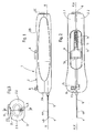
- Figures 1, 2 and 3 are respectively external views in plane, from above and from the side of an exemplary embodiment of the sampling according to the invention.
- FIG. 4 is an exploded perspective view of said device showing its different components.
- FIGS. 6A, 6B, 6C, 6D, 6E, 6F, 6G and 6H are views in section along the line I-I of FIGS. 5A, 5B, 5C, 5D, 5E, 5F, 5G and 5H showing the different stages of operation of the control of said device.
- FIGS. 7A, 7B, 7C, 7D and 7E are perspective views, delimited by a rectangular frame of said operating knob acting on the stops of the sliders in the positions occupied by the device in FIGS. 5A to 5E respectively.
- the sampling device 1 of a body tissue sample shown in Figures 1 to 3, comprises a similar gripping housing 2 to a handle and whose outer shape substantially parallelepiped rounded, anatomical, allowing the practitioner to grasp appropriately and easily use the device with one hand.
- the front trigger 8 and the rear trigger 9 of a firing trigger mechanism of said needle and cannula are accessible from the outside of the housing and are respectively provided on the top housing, near its front face 2A, and on its rear face 2C.
- the housing of gripping 2 consists of two half-shells 2.1, 2.2 assembled between them to define a median longitudinal plane P-P of said housing, and a inner housing 10 inside which are mounted the different components of the sampling device 1 which will be described below in FIGS. 4, 5A, 6A and 7A.
- the slide 12 with cannula 5 is at the front of the housing 2, while that the slider 11 with needle 4 is located behind, that is to say turned towards the back of the housing, its needle 4 through the cannula 5 and the slider associated 12 to the output of its distal tapered tip 4B of the cannula.
- Springs 14, 15 are also associated respectively with the slides being arranged along the longitudinal axis X-X of the sliders.
- the cannulated slide 12 abuts against a fixed front leg 2D housing under the action of the spring 15 disposed between the slider and a fixed intermediate leg 2E of the housing, and the needle slide 11 is pressed against the fixed intermediate leg 2E, on the other side, under the action spring 14 disposed between the slider and a third fixed rear leg 2F of the housing.
- These springs are compression type and identical. These three legs are for example protruding from the half-shell 2.1 of the housing, transversely at its longitudinal plane P-P.
- said slides 11, 12 occupy a forward position in the housing 2, for which the needle 4 and cannula 5 are in the initial rest position, unarmed, largely out front panel 2A housing.
- the slides 11, 12 cooperate, in their movement, with 2G guides from half-shells 2.1 and 2.2 and engaging in respective lateral grooves 11A, 12A thereof.
- the button control 6 makes it possible to bring the sliders 11 into the rear position, 12, against the respective springs 14, 15, rear position for which the needle 4 and cannula 5 are then in retracted position armed, ready for sampling, as will be seen later in look at Figure 5D.
- the latter are provided with respective stops 16, 17 which are transversely offset with respect to the other, and the control button comprises a lug 18 movable transversely, that is, perpendicular to the plane P-P, under the action of displacement means and which can act sequentially on the stops.
- the stop 17 is standing vertically at the rear end of the cannulated slide 12 and present, for example, an angled L-shape in which can engage the movable pin 18 associated with the control button 6.
- the other stop 16 is erected vertically on the slider 11 with needle, in being located substantially at the same height as the abutment 17 of the slider 12 (FIGS. 5A, 7A), but shifted transversely of said stop 17 ( Figures 6A, 7A).
- the stop 16 of the needle slide is also bent for a safe and reliable engagement of said pin 18. This last protrude vertically downward from said button 6 to just come to the level slides and it comes from a base 19 housed inside the button and mounted transversely sliding therein by a connection to slide 20.
- the means for moving the lug 18 advantageously comprise a spring 21 arranged transversely against a side wall 6A of the button and a recess 19A formed in the base, and a inclined ramp 22 provided inside the housing and secured to the half-shell 2.1 from which it comes.
- the spring 21 of the compression type ensures the passage of the lug 18 of a retracted position, for which the slider 12 is moved by its abutment 17 towards its rear position, at an extended position, for which the other slider 11 is moved backwards via its stop 16 transversely offset from that of the slide 12.
- the ramp 22 returns said pin 18 in the retracted position, compressing the spring 21, when returning to the initial position of the button 6.
- FIGS. 6A and 7A show in particular that the inclined ramp 22 ends with an end edge 22A parallel to the X-X axis, on which applies the lug in the initial position of the button, and which is advantageously located in the extension of the corresponding side 17A of the stop 17 in L.
- control button 6 is maintained in initial position by a tension spring 23 connecting it to the half-shell 2.1 of the housing and bringing it against the front edge 7A of the opening oblong 7 of said housing.
- each slide 11, 12 comprises, in this example embodiment, an elastically deformable longitudinal tab 11B, 12B terminated by a hook 11C, 12C, adapted to engage with a stop corresponding fixed 2J, 2H transversely protruding from the half-shell 2.1 of the housing.
- the trigger before 8 and the rear trigger 9 can be operated independently each other according to the preference of the practitioner, while being advantageously mechanically connected to each other to influence the means of blocking 11B, 11C, 2J - 12B, 12C, 2H in the rear position of the slides.
- the front trigger 8 is derived from a lever 8A pivoted about a 2K axis located in front of the half-shell and arranged orthogonally to the X-X axis or to the P-P longitudinal plane of the housing 2.
- the rear trigger 9 it is of the push-button type 9A with longitudinal displacement, with a return spring 9B provided therebetween and the rear face 2C of the housing, and provided with a protruding leg 9C longitudinally inside said housing.
- This tab 9C is intended for come into contact with the blocking means 11B, 11C to erase them and release the rear slide 11, which also comprises a longitudinal tab 11D, opposite to that 11B, to act on the locking means 12B, 12C of the slider 12 in the housing, as will be seen later.
- Swing lever 8A of the front trigger and the push button 9A of the rear trigger are connected by a rod or rod 24 current to the inside of the housing and engaging by its ends in corresponding holes 8B, 9E provided in the lever 8A and the tab 9C of the pushbutton.
- a rod or rod 24 current to the inside of the housing and engaging by its ends in corresponding holes 8B, 9E provided in the lever 8A and the tab 9C of the pushbutton.
- the trigger before 8 is slightly offset transversely to the longitudinal plane P-P housing 1.
- This transverse shift is a security for the trigger mechanism that can only be made active if the practitioner brings it back in the longitudinal plane P-P.
- this security is defined by a notch 2L extending transversely the opening 2M formed in the top of the housing for the passage of the lever 8A of the front trigger, which lever can slide transversely on its axis 2K to be brought into the slot 2L or out of it by the practitioner.
- This trigger before 8 (and, therefore, the trigger mechanism) is made operational only if the practitioner moves it transversely towards the longitudinal plane according to the arrow F3.
- sampling device 1 The operation of the sampling device 1 according to the invention will now be described.
- the arming of the device 1 is done with one hand and sequentially, by two successive movements towards the rear of the control button 6 which acts, at first, on the slider 12 with cannula 5 and, secondly, on the needle slide 11 4.
- the practitioner can then proceed with the sampling shot, as the show FIGS. 5F, 5G and 5H.
- the shot can be fired either with the trigger before 8, making pivoting its lever 8A according to the arrow F1 of FIG. 5F about the axis 2K, with the rear trigger 9, pushing the push-button forward 9A according to the arrow F2.
- the practitioner will have brought the trigger before 8 in the longitudinal plane P-P, acting for that on this according to the arrow F3 of Figures 2 and 3, which makes the lever slide 8A on its 2K axis and away from the notch 2L. Security is then erased and the triggering mechanism is made operational.
- FIG. 5F shows that the sloping end of the tab 9D 9C longitudinal pushbutton is applied on the hook 11C of the elastic tab 11B of the slider 11 to deform elastically and disengage the hook 11C from the corresponding fixed stop 2J.
- the triggers 8, 9 return to the initial position under the action of the return spring 9B.
- the practitioner then removes the needle and cannula device 1 of the patient.
Abstract
Description
La présente invention concerne un dispositif pour prélever un échantillon de tissu ou d'organe corporel sur un être humain ou animal à des fins d'examen.The present invention relates to a device for taking a tissue sample or body organ on a human being or animal to examination purposes.
Le prélèvement d'échantillon, désigné généralement par le terme de biopsie, est devenu un acte médical de plus en plus pratiqué puisqu'il permet entre autres opérations de diagnostiquer des états maladifs à la suite de différents examens de l'échantillon prélevé et d'atteindre, sans lésion, des organes profonds tels que le foie et les reins.Sample collection, usually referred to as biopsy, has become a medical procedure that is increasingly practiced since allows among other operations to diagnose disease states at the following various examinations of the sample taken and to reach, without lesion, deep organs such as the liver and kidneys.
Aussi, de nombreux dispositifs de prélèvement ont-ils été développés pour répondre à la demande avec pour objectif de faciliter leur utilisation par les praticiens et de garantir une fiabilité de fonctionnement élevée.Also, many sampling devices have been developed to meet the demand with the aim of facilitating their use by practitioners and to ensure high operating reliability.
On connaít déjà de nombreux dispositifs pour prélever des échantillons corporels et ils comportent généralement :
- une aiguille dont l'extrémité distale forme un évidement apte à recevoir ledit échantillon ;
- une canule entourant coaxialement ladite aiguille, lesdites aiguille et canule pouvant coulisser l'une par rapport à l'autre ;
- des coulisseaux associés respectivement auxdites aiguille et canule ;
- des ressorts associés respectivement auxdits coulisseaux ;
- un boítier de préhension de forme allongée, définissant un logement interne à l'intérieur duquel sont agencés en série, selon un axe longitudinal dudit boítier, lesdits coulisseaux pouvant coulisser entre une position avant dans le boítier, pour laquelle lesdites aiguille et canule sont en position de repos, prêtes à être armées pour un tir de prélèvement, et une position arrière, pour laquelle lesdites aiguille et canule sont en position rétractée armée, prêtes pour ledit tir ;
- un bouton de commande pour amener en position arrière lesdits coulisseaux à l'encontre desdits ressorts respectifs ;
- des moyens de blocage desdits coulisseaux en position arrière ; et
- un mécanisme de déclenchement pour effacer lesdits moyens de blocage et entraíner, sous l'action desdits ressorts, le déplacement en position avant desdits coulisseaux et le tir de prélèvement desdites aiguille et canule.
- a needle whose distal end forms a recess adapted to receive said sample;
- a cannula coaxially surrounding said needle, said needle and cannula being slidable relative to each other;
- slides respectively associated with said needle and cannula;
- springs associated respectively with said sliders;
- an elongated housing for gripping, defining an internal housing inside which are arranged in series, along a longitudinal axis of said housing, said sliders being slidable between a forward position in the housing, for which said needle and cannula are in position resting, ready to be armed for a draw shot, and a rear position, for which said needle and cannula are in the retracted armed position, ready for said firing;
- a control button for bringing said sliders back into position against said respective springs;
- locking means of said sliders in the rear position; and
- a trigger mechanism for erasing said locking means and causing, under the action of said springs, the displacement in the forward position of said slides and the firing of said needle and cannula.
De tels dispositifs sont par exemple enseignés par les brevets européens EP-0 238 461 et EP-0 435 986.Such devices are for example taught by patents EP-0 238 461 and EP-0 435 986.
Ces dispositifs décrits nécessitent l'usage des deux mains du praticien pour charger simultanément les coulisseaux portant respectivement l'aiguille et la canule, à l'encontre des ressorts, ce qui n'est pas toujours facile à réaliser.These described devices require the use of both hands of the practitioner to simultaneously load the slides respectively the needle and the cannula, against the springs, which is not always easy to make.
L'invention a pour objet de proposer un dispositif de prélèvement dont la conception, structurellement simple, permet notamment au praticien de faire passer lesdites aiguille et canule en position armée, d'une seule main.The object of the invention is to propose a sampling device whose design, structurally simple, allows in particular the practitioner to pass said needle and cannula in an armed position, only hand.
A cet effet, le dispositif de prélèvement du type préalablement décrit est remarquable, selon l'invention, en ce que lesdits coulisseaux comportent des butées qui sont transversalement décalées l'une par rapport à l'autre et en ce que ledit bouton de commande comprend un ergot mobile transversalement sous l'action de moyens de déplacement, et agissant séquentiellement sur lesdites butées décalées pour amener l'un après l'autre lesdits coulisseaux en position arrière.For this purpose, the sampling device of the type previously described is remarkable, according to the invention, in that said sliders comprise stops which are transversely offset relative to each other to the other and in that said control knob comprises a lug transversely under the action of moving means, and acting sequentially on said staggered stops to bring the one after the other said sliders in the rear position.
Ainsi, grâce à l'invention, un seul bouton de commande permet le chargement séquentiel de l'aiguille et de la canule qui s'effectue en deux mouvements distincts : un premier mouvement de translation du bouton depuis une position initiale, qui amène par exemple le coulisseau à canule en position armée et, après retour dudit bouton en position initiale, un second mouvement de translation qui amène le coulisseau à aiguille en position armée.Thus, thanks to the invention, a single command button allows the Sequential loading of the needle and cannula in two distinct movements: a first movement of the button from an initial position, which brings for example the cannulated slide in the armed position and, after returning said button to the initial position, a second translational motion that brings the needle slider into position army.
L'utilisation du dispositif est simple et aisée puisque le praticien peut armer celui-ci d'une seule main à l'aide de son pouce.The use of the device is simple and easy since the practitioner can arm it with one hand with his thumb.
Par exemple, lesdits moyens de déplacement peuvent comprendre un ressort disposé transversalement entre ledit bouton et ledit ergot et permettant le passage de ce dernier d'une position rentrée pour laquelle l'un desdits coulisseaux est déplacé en position arrière via sa butée, à une position sortie pour laquelle l'autre coulisseau est déplacé en position arrière via sa butée décalée, et une rampe inclinée, prévue à l'intérieur dudit boítier et qui ramène ledit ergot de sa position sortie vers sa position rentrée, lors du retour en position initiale dudit bouton.For example, said moving means may comprise a spring disposed transversely between said button and said pin and allowing the passage of the latter from a retracted position for which one of said slides is moved in the rear position via its abutment, at a output position for which the other slider is moved into position rear via its staggered stop, and an inclined ramp, provided inside said housing and which brings said pin from its extended position to its position returned, when returning to the initial position of said button.
Avantageusement, ladite rampe inclinée se termine par un bord d'extrémité latéral sur lequel s'applique, en position initiale dudit bouton, ledit ergot comprimant son ressort, et qui est situé au même niveau que la butée du coulisseau à déplacer en premier. Ainsi, l'ergot est maintenu en position rentrée et engage la butée du coulisseau correspondant aussitôt le déplacement du bouton de commande. L'ergot est lié audit bouton, par exemple, par une liaison à glissière et peut coulisser transversalement via celle-ci sous l'action des moyens de déplacement.Advantageously, said inclined ramp ends with an edge side end on which applies, in the initial position of said button, said lug compressing its spring, and which is located at the same level as the stop of the slide to move first. Thus, the ergot is maintained in position retracted and engages the stop of the slider corresponding immediately the movement of the control button. The pin is linked to said button, by example, by a slide connection and can slide transversely via it under the action of the moving means.
En particulier, ledit coulisseau à canule et son ressort sont situés du côté avant dudit boítier et sont amenés en premier en position arrière, armée via ledit ergot, tandis que ledit coulisseau à aiguille et son ressort sont coaxialement situés du côté arrière dudit boítier et sont déplacés en second en position arrière, armée, le déplacement desdits coulisseaux et ressorts étant limité par des pattes fixes solidaires dudit boítier. In particular, said cannula slide and its spring are located on the front side of said housing and are brought first in the rear position, armed via said pin, while said needle slide and its spring are coaxially located on the rear side of said housing and are moved in second in rear position, armed, moving said slides and springs being limited by fixed tabs secured to said housing.
De préférence, ledit bouton de commande est monté longitudinalement coulissant à travers une ouverture oblongue dudit boítier et un ressort disposé longitudinalement relie ledit boítier audit bouton pour rappeler spontanément ce dernier dans sa position initiale, contre le bord avant correspondant de ladite ouverture.Preferably, said control button is mounted longitudinally sliding through an oblong opening of said housing and a spring disposed longitudinally connects said housing audit button to remind spontaneously the latter in its initial position, against the corresponding front edge of said opening.
Dans un mode préféré de réalisation, lesdits moyens de blocage comportent au moins une patte à crochet élastiquement déformable issue de chaque coulisseau, et une butée fixe correspondante prévue à l'intérieur dudit boítier et sur laquelle s'engage la patte à crochet du coulisseau correspondant quand celui-ci arrive en position arrière.In a preferred embodiment, said blocking means comprise at least one elastically deformable hook tab of each slider, and a corresponding fixed stop provided inside said housing and on which engages the bracket hook hook corresponding when it arrives in the rear position.
En ce qui concerne ledit mécanisme de déclenchement dudit tir de prélèvement, il comporte avantageusement, sur ledit boítier, une gâchette avant et une gâchette arrière actionnables indépendamment l'une de l'autre et agissant sur lesdits moyens de blocage. Le praticien peut se servir de l'une ou l'autre desdites gâchettes pour déclencher le tir. De préférence, lesdites gâchettes avant et arrière sont reliées mécaniquement entre elles par une tige de liaison agencée à l'intérieur dudit boítier.With regard to said triggering mechanism of said shot of sampling, it advantageously comprises, on said housing, a trigger front and rear trigger can be operated independently of each other and acting on said blocking means. The practitioner can use one or the other of said triggers to trigger the shot. Preferably, said forward and reverse triggers are mechanically connected between them by a connecting rod arranged inside said housing.
Dans un mode préféré de réalisation, ladite gâchette arrière comprend un bouton-poussoir avec ressort de rappel et muni d'une patte agencée en saillie dans ledit boítier pour libérer lesdits moyens de blocage dudit coulisseau à aiguille, et ledit coulisseau à aiguille est équipé, de plus, d'une patte agencée en saillie pour agir sur lesdits moyens de blocage dudit coulisseau à canule, par suite de son déplacement vers la position avant. Ainsi, l'éjection du coulisseau à aiguille a tout d'abord lieu, puis celle du coulisseau à canule, ce qui permet de recueillir l'échantillon corporel entre les déplacements successifs des coulisseaux en position avant.In a preferred embodiment, said rear trigger includes a push button with return spring and with a leg arranged in projection in said housing to release said locking means said needle slide, and said needle slide is furthermore equipped with a tab arranged projecting to act on said locking means of said cannula slide, as a result of its displacement towards the position before. Thus, the ejection of the needle slide first takes place, then that of the cannulated slide, which allows to collect the body sample between the successive displacements of the sliders in the forward position.
Quant à ladite gâchette avant, elle peut comprendre un levier pivotant autour d'un axe dudit boítier orthogonal à son axe longitudinal, ladite tige de liaison reliant ledit levier de la gâchette avant audit bouton-poussoir de la gâchette arrière. Avantageusement, le dispositif comprend une sécurité pour rendre inopérationnel ledit mécanisme de déclenchement. Par exemple, elle consiste en une encoche ménagée dans ledit boítier et dans laquelle peut être reçue ladite gâchette avant par suite d'un déplacement transversal. Le mécanisme de déclenchement est alors immobilisé.As for said front trigger, it may include a pivoting lever around an axis of said housing orthogonal to its longitudinal axis, said connecting rod connecting said lever of the trigger before said push button the rear trigger. Advantageously, the device comprises security to render said triggering mechanism inoperative. For example, it consists of a notch formed in said housing and wherein said forward trigger can be received as a result of a transverse displacement. The trigger mechanism is then immobilized.
Par ailleurs, ledit boítier se compose, de préférence, de deux demi-coques assemblées entre elles le long d'un plan longitudinal.Moreover, said housing is preferably composed of two half-shells assembled together along a longitudinal plane.
Les figures du dessin annexé feront bien comprendre comment l'invention peut être réalisée. Sur ces figures, des références identiques désignent des éléments semblables.The figures of the annexed drawing will make clear how the invention can be realized. In these figures, identical references designate similar elements.
Les figures 1, 2 et 3 sont respectivement des vues extérieures en plan, de dessus et latérale d'un exemple de réalisation du dispositif de prélèvement selon l'invention.Figures 1, 2 and 3 are respectively external views in plane, from above and from the side of an exemplary embodiment of the sampling according to the invention.
La figure 4 est une vue en perspective éclatée dudit dispositif montrant ses différents composants.FIG. 4 is an exploded perspective view of said device showing its different components.
Les figures 5A, 5B, 5C, 5D, 5E, 5F, 5G et 5H sont des vues en coupe longitudinale dudit dispositif montrant les différentes étapes de fonctionnement, à savoir :
- coulisseaux à aiguille et à canule en position repos ;
- premier déplacement du bouton de commande pour l'armement du coulisseau à canule ;
- retour du bouton de commande en position initiale ;
- second déplacement du bouton de commande pour l'armement du coulisseau à aiguille ;
- retour du bouton de commande en position initiale ;
- commande du tir par le mécanisme de déclenchement et action sur les moyens de blocage du coulisseau à aiguille ;
- sortie du coulisseau à aiguille et action sur les moyens de blocage du coulisseau à canule ; et
- sortie du coulisseau à canule.
- needle and cannula slides in the rest position;
- first movement of the control knob for arming the cannulated slide;
- return of the control knob to the initial position;
- second movement of the control knob for arming the needle slide;
- return of the control knob to the initial position;
- firing control by the triggering mechanism and action on the locking means of the needle slide;
- output of the needle slide and action on the blocking means of the cannulated slide; and
- exit of the cannulated slide.
Les figures 6A, 6B, 6C, 6D, 6E, 6F, 6G et 6H sont des vues en coupe selon la ligne I-I des figures 5A, 5B, 5C, 5D, 5E, 5F, 5G et 5H montrant les différentes étapes de fonctionnement du bouton de commande dudit dispositif.FIGS. 6A, 6B, 6C, 6D, 6E, 6F, 6G and 6H are views in section along the line I-I of FIGS. 5A, 5B, 5C, 5D, 5E, 5F, 5G and 5H showing the different stages of operation of the control of said device.
Les figures 7A, 7B, 7C, 7D et 7E sont des vues en perspective, délimitées par un cadre rectangulaire dudit bouton de commande agissant sur les butées des coulisseaux dans les positions occupées par le dispositif sur les figures 5A à 5E respectivement.FIGS. 7A, 7B, 7C, 7D and 7E are perspective views, delimited by a rectangular frame of said operating knob acting on the stops of the sliders in the positions occupied by the device in FIGS. 5A to 5E respectively.
Le dispositif de prélèvement 1 d'un échantillon tissulaire corporel,
montré sur les figures 1 à 3, comporte un boítier de préhension 2 analogue
à une poignée et dont la forme extérieure, sensiblement parallélépipédique
arrondie, est anatomique, permettant au praticien de saisir convenablement
et d'utiliser aisément le dispositif d'une main.The
De la face avant 2A du boítier émergent une aiguille 4 avec un
évidement 4A et une canule 5 de prélèvement entourant coaxialement
l'aiguille, à l'exception de la pointe d'introduction biseautée 4B, tandis
qu'un bouton de commande 6 est accessible de la face de dessus 2B du
boítier, à travers une ouverture 7 ménagée dans celui-ci. Egalement, on
voit sur ces figures que la gâchette avant 8 et la gâchette arrière 9 d'un
mécanisme de déclenchement du tir desdites aiguille et canule sont accessibles
de l'extérieur du boítier et sont respectivement prévues sur le dessus
du boítier, près de sa face avant 2A, et sur sa face arrière 2C.From the
Comme le montre plus particulièrement la figure 4, le boítier de
préhension 2 est constitué de deux demi-coques 2.1, 2.2 assemblées
entre elles pour définir un plan longitudinal médian P-P dudit boítier, et un
logement intérieur 10 à l'intérieur duquel sont montés les différents
composants du dispositif de prélèvement 1 qui seront décrits ci-après en
regard des figures 4, 5A, 6A et 7A.As shown more particularly in Figure 4, the housing of
gripping 2 consists of two half-shells 2.1, 2.2 assembled
between them to define a median longitudinal plane P-P of said housing, and a
Dans le logement interne 10 du boítier 2, sont prévus deux coulisseaux
11, 12 agencés en série et portant respectivement l'aiguille 4 et la
canule 5 selon un même axe longitudinal X-X. Dans le mode de réalisation
illustré, le coulisseau 12 à canule 5 se trouve à l'avant du boítier 2, tandis
que le coulisseau 11 à aiguille 4 est situé derrière, c'est-à-dire tourné vers
l'arrière du boítier, son aiguille 4 traversant la canule 5 et le coulisseau
associé 12 jusqu'à la sortie de sa pointe biseautée distale 4B de la canule.
Des ressorts 14, 15 sont également associés respectivement aux coulisseaux
en étant agencés suivant l'axe longitudinal X-X des coulisseaux.
Ainsi, le coulisseau 12 à canule est en butée contre une patte avant fixe
2D du boítier sous l'action du ressort 15 disposé entre le coulisseau et
une patte intermédiaire fixe 2E du boítier, et le coulisseau 11 à aiguille est
pressé contre la patte intermédiaire fixe 2E, de l'autre côté, sous l'action
du ressort 14 disposé entre le coulisseau et une troisième patte arrière fixe
2F du boítier. Ces ressorts sont du type à compression et identiques. Ces
trois pattes font par exemple saillie de la demi-coque 2.1 du boítier, transversalement
à son plan longitudinal P-P.In the
Ainsi, sous l'action de ces ressorts, lesdits coulisseaux 11, 12
occupent une position avant dans le boítier 2, pour laquelle les aiguille 4
et canule 5 sont en position de repos initiale, non armée, largement sortie
de la face avant 2A du boítier.Thus, under the action of these springs, said slides 11, 12
occupy a forward position in the
Bien évidemment, les coulisseaux 11, 12 coopèrent, dans leur déplacement,
avec des guides 2G issus des demi-coques 2.1 et 2.2 et s'engageant
dans des rainures latérales respectives 11A, 12A de ceux-ci.Of course, the
Par un déplacement vers l'arrière, parallèle à l'axe X-X, le bouton
de commande 6 permet d'amener en position arrière les coulisseaux 11,
12, à l'encontre des ressorts respectifs 14, 15, position arrière pour
laquelle les aiguille 4 et canule 5 sont alors en position rétractée armée,
prêtes pour le tir de prélèvement, comme on le verra ultérieurement en
regard de la figure 5D. Avantageusement, pour amener séquentiellement
les coulisseaux en position arrière, ces derniers sont munis de butées respectives
16, 17 qui sont transversalement décalées l'une par rapport à
l'autre, et le bouton de commande comprend un ergot 18 mobile transversalement,
c'est-à-dire perpendiculairement au plan P-P, sous l'action de
moyens de déplacement et qui peut agir séquentiellement sur les butées.By moving backwards, parallel to the X-X axis, the
Comme le montrent les figures 4, 5A, 6A et 7A, la butée 17 est
dressée verticalement à l'extrémité arrière du coulisseau 12 à canule et
présente, par exemple, une forme coudée en L dans laquelle peut s'engager
l'ergot mobile 18 associé au bouton de commande 6. De même, l'autre
butée 16 est dressée verticalement sur le coulisseau 11 à aiguille, en
étant située sensiblement à la même hauteur que la butée 17 du coulisseau
12 (figures 5A, 7A), mais décalée transversalement de ladite butée
17 (figures 6A, 7A). La butée 16 du coulisseau à aiguille est également
coudée pour un engagement sûr et fiable dudit ergot 18. Ce dernier fait
saillie verticalement vers le bas dudit bouton 6 pour venir juste au niveau
des coulisseaux et il est issu d'une embase 19 logée à l'intérieur du bouton
et montée transversalement coulissante dans celui-ci par une liaison à
glissière 20.As shown in FIGS. 4, 5A, 6A and 7A, the
Les moyens de déplacement de l'ergot 18 comprennent avantageusement
un ressort 21 disposé transversalement contre une paroi latérale
6A du bouton et un évidement 19A ménagé dans l'embase, et une
rampe inclinée 22 prévue à l'intérieur du boítier et solidaire de la demi-coque
2.1 dont elle est issue.The means for moving the
Ainsi, le ressort 21 du type à compression assure le passage de
l'ergot 18 d'une position rentrée, pour laquelle le coulisseau 12 est déplacé
par sa butée 17 vers sa position arrière, à une position sortie, pour
laquelle l'autre coulisseau 11 est déplacé vers l'arrière via sa butée 16
décalée transversalement par rapport à celle du coulisseau 12. Et la rampe
22 ramène ledit ergot 18 en position rentrée, comprimant le ressort 21,
lors du retour en position initiale du bouton 6.Thus, the
On voit notamment sur les figures 6A, 7A que la rampe inclinée
22 se termine par un bord d'extrémité 22A parallèle à l'axe X-X, sur lequel
s'applique l'ergot en position initiale du bouton, et qui est avantageusement
situé dans le prolongement du côté correspondant 17A de la butée
17 en L.FIGS. 6A and 7A show in particular that the
On remarque également que le bouton de commande 6 est maintenu
en position initiale par un ressort de traction 23 le reliant à la demi-coque
2.1 du boítier et l'amenant contre le bord avant 7A de l'ouverture
oblongue 7 dudit boítier.Note also that the
Par ailleurs, le dispositif 1 comporte aussi des moyens de blocage
pour immobiliser les coulisseaux 11, 12 lorsqu'ils occupent la position
arrière. Pour cela, chaque coulisseau 11, 12 comprend, dans cet exemple
de réalisation, une patte longitudinale élastiquement déformable 11B, 12B
terminée par un crochet 11C, 12C, apte à s'encliqueter avec une butée
fixe correspondante 2J, 2H faisant transversalement saillie de la demi-coque
2.1 du boítier.Furthermore, the
En ce qui concerne le mécanisme de déclenchement, la gâchette
avant 8 et la gâchette arrière 9 peuvent être actionnées indépendamment
l'une de l'autre selon la préférence du praticien, tout en étant avantageusement
reliées mécaniquement entre elles pour agir sur les moyens de
blocage 11B, 11C, 2J - 12B, 12C, 2H en position arrière des coulisseaux.Regarding the trigger mechanism, the trigger
before 8 and the
Structurellement, la gâchette avant 8 est issue d'un levier 8A
monté pivotant autour d'un axe 2K situé en partie avant de la demi-coque
et disposé orthogonalement à l'axe X-X ou au plan longitudinal P-P du boítier
2. Quant à la gâchette arrière 9, elle est du type à bouton-poussoir 9A
à déplacement longitudinal, avec un ressort de rappel 9B prévu entre celui-ci
et la face arrière 2C du boítier, et muni d'une patte 9C faisant saillie
longitudinalement à l'intérieur dudit boítier. Cette patte 9C est destinée à
venir au contact des moyens de blocage 11B, 11C pour les effacer et libérer
le coulisseau arrière 11, lequel comporte également une patte longitudinale
11D, opposée à celle 11B, pour agir sur les moyens de blocage
12B, 12C du coulisseau 12 dans le boítier, comme on le verra ultérieurement.Structurally, the
Le levier pivotant 8A de la gâchette avant et le bouton-poussoir
9A de la gâchette arrière sont reliés par une tige ou tringle 24 courant à
l'intérieur du boítier et s'engageant par ses extrémités dans des trous correspondants
8B, 9E prévus dans le levier 8A et la patte 9C du bouton-poussoir.
Ainsi, une action sur l'une quelconque des gâchettes entraíne le
déplacement de la patte 9C agissant sur les moyens de blocage.
On remarque par ailleurs, sur les figures 2 et 3, que la gâchette
avant 8 est légèrement décalée transversalement par rapport au plan longitudinal
P-P du boítier 1. Ce décalage transversal constitue une sécurité
pour le mécanisme de déclenchement qui ne peut être rendu actif que si le
praticien le ramène dans le plan longitudinal P-P. Pour cela, cette sécurité
est définie par une encoche 2L prolongeant transversalement l'ouverture
2M ménagée dans le dessus du boítier pour le passage du levier 8A de la
gâchette avant, lequel levier peut coulisser transversalement sur son axe
2K pour être amené dans l'encoche 2L ou sorti de celle-ci par le praticien.
Cette gâchette avant 8 (et, donc, le mécanisme de déclenchement) n'est
rendue opérationnelle que si le praticien la déplace transversalement vers
le plan longitudinal selon la flèche F3.Note also, in Figures 2 and 3, that the trigger
before 8 is slightly offset transversely to the longitudinal plane
Le fonctionnement du dispositif de prélèvement 1 selon l'invention
sera maintenant décrit. The operation of the
Le dispositif se trouve initialement dans la configuration illustrée sur les figures 1, 2, 5A, 6A et 7A, pour laquelle :
- les coulisseaux 11, 12 occupent la position avant dans le boítier, en
butée contre les pattes avant et intermédiaire respectives 2B, 2E, sous
l'action des ressorts 14, 15, position pour laquelle les canule 5
et aiguille 4 sont en position initiale sortie, de repos ; la pointe biseautée de la canule 5recouvrant l'évidement 4A de l'aiguille ; - le bouton de commande 6 est en position initiale avant par l'action du ressort 23, contre le bord avant 7A de l'ouverture du boítier 2 ;
l'ergot 18 se trouve en contact avec le bord d'extrémité latéral 22A de la rampe inclinée ; et- le mécanisme de déclenchement 8, 9 est inactif.
- the
slides intermediate legs springs cannula 5 andneedle 4 are in the initial position out , rest ; the beveled tip of thecannula 5 covering therecess 4A of the needle; - the
control knob 6 is in the initial position before by the action of thespring 23, against thefront edge 7A of the opening of thehousing 2; - the
lug 18 is in contact with thelateral end edge 22A of the inclined ramp; and - the
trigger mechanism
Quand le praticien souhaite procéder à l'armement du dispositif 1,
il recule, à l'aide de son pouce, le bouton de commande 6 jusqu'à ce qu'il
vienne en butée contre le bord arrière 7B de l'ouverture 7. Comme le montrent
les figures 5B, 6B et 7B, dès le commencement du déplacement longitudinal
vers l'arrière du bouton, l'ergot 18 s'engage dans la butée coudée
17 du coulissement 12, laquelle est située dans le prolongement du
bord d'extrémité 22A de la rampe 22. L'ergot 18 reste sur sa position
transversale initiale avec son ressort comprimé puisqu'il s'applique contre
le côté 17A de la butée. Ainsi, le coulisseau 12 est entraíné et passe de
sa position avant à sa position arrière, en comprimant son ressort 15, jusqu'à
l'engagement du crochet 12C de sa patte élastiquement déformable
12B avec la butée correspondante 2H du boítier. La canule 5, qui a reculé
avec son coulisseau, se trouve alors en position armée. On découvre sur la
figure 5B l'évidement de prélèvement 4A de l'aiguille 4.When the practitioner wishes to arm the
Quand le bouton de commande 6 revient de sa position arrière
vers sa position avant via son ressort 23, comme le montrent les figures
5C, 6C et 7C, l'ergot 18 quitte la butée 17 du coulisseau 12, de sorte
qu'il se déplace transversalement en position sortie par l'action du ressort
21 qui se détend et déplace l'embase 19 via la liaison 20. Puis, quand
l'ergot touche la rampe inclinée 22, il suit celle-ci et reprend sa position
rentrée montrée sur les figures 5C, 6C et 7C, jusqu'à venir sur le bord
d'extrémité 22A de la rampe, en ramenant l'embase 19 et en comprimant
ainsi son ressort associé 21. Le bouton 6 occupe alors sa position initiale
sous l'action de son ressort, contre le bord avant 7A.When the
Après l'armement de la canule, le praticien procède à celui de l'aiguille
4. Pour cela, comme le montrent les figures 5D, 6D et 7D, il recule
à nouveau, à l'aide de son pouce, le bouton de commande 6 jusqu'à ce
qu'il vienne en butée contre le bord arrière 7B de l'ouverture, entraínant
l'étirement du ressort 23. Durant ce déplacement longitudinal arrière du
bouton, comme le coulisseau 12 à canule est en position arrière, l'ergot
18 quitte le bord d'extrémité 22A de la rampe, puis suit son bord incliné
par le déplacement transversal de son ressort 21 faisant coulisser son
embase 19. Par ce décalage transversal perpendiculaire au plan P du dispositif,
produit par le passage du ressort de son état comprimé à son état
détendu, l'ergot 18 s'engage alors dans la butée coudée 16 du coulisseau
11 à aiguille et l'entraíne ainsi jusqu'à sa position arrière. Arrivé dans
celle-ci, le crochet 11C de sa patte longitudinale 11B élastiquement déformable,
engage la butée correspondante 2J du boítier, de sorte que le
coulisseau 11 est verrouillé dans sa position arrière, le ressort 14 étant
comprimé et son aiguille 4 étant armée, revenue dans la canule.After arming the cannula, the practitioner proceeds to that of the
Quand le praticien relâche le bouton 6, celui-ci est amené élastiquement
via le ressort 23 vers sa position initiale, contre le bord avant 7A
de l'ouverture 7, et l'ergot 18 s'applique à nouveau contre le bord d'extrémité
22A de la rampe 22, le ressort se comprimant en ramenant l'embase
19. Le dispositif 1 est alors en position armée, prêt au tir de prélèvement,
comme le montrent les figures 5E, 6E et 7E. When the practitioner releases the
Ainsi, l'armement du dispositif 1 s'effectue d'une seule main et de
façon séquentielle, par deux déplacements successifs vers l'arrière du
bouton de commande 6 qui agit, dans un premier temps, sur le coulisseau
12 à canule 5 puis, dans un second temps, sur le coulisseau 11 à aiguille
4.Thus, the arming of the
Le praticien peut alors procéder au tir de prélèvement, comme le montrent les figures 5F, 5G et 5H.The practitioner can then proceed with the sampling shot, as the show FIGS. 5F, 5G and 5H.
Le tir peut être déclenché soit avec la gâchette avant 8, en faisant
pivoter son levier 8A selon la flèche F1 de la figure 5F autour de l'axe 2K,
soit avec la gâchette arrière 9, en poussant vers l'avant le bouton-poussoir
9A selon la flèche F2. Mais, au préalable, le praticien aura amené la gâchette
avant 8 dans le plan longitudinal P-P, en agissant pour cela sur
celle-ci selon la flèche F3 des figures 2 et 3, ce qui fait coulisser le levier
8A sur son axe 2K et l'éloigne de l'encoche 2L. La sécurité est alors effacée
et le mécanisme de déclenchement est rendu opérationnel.The shot can be fired either with the trigger before 8, making
pivoting its
On voit sur la figure 5F que l'extrémité à pan incliné 9D de la patte
longitudinale 9C du bouton-poussoir vient s'appliquer sur le crochet 11C
de la patte élastique 11B du coulisseau 11 jusqu'à la déformer élastiquement
et dégager le crochet 11C de la butée fixe correspondante 2J.FIG. 5F shows that the sloping end of the
Comme le montre la figure 5G, sous l'action du ressort comprimé
14, le coulisseau 11 se déplace contre la patte ou butée intermédiaire fixe
2E, ce qui entraíne la sortie de l'aiguille et sa pénétration dans le tissu
corporel (non représenté) du patient. On voit sur la figure 6G, que la butée
16 du coulisseau 11 est revenue dans sa position de départ, proche de
l'ergot 18. Juste avant que le coulisseau 11 à aiguille n'atteigne sa butée
2E, la patte longitudinale avant 11D de ce coulisseau s'applique contre le
crochet 12C de la patte élastiquement déformable 12B du coulisseau 12 à
canule et agit sur celle-ci pour la dégager de sa butée 2H. Comme le montre
la figure 5H, cela a pour effet d'entraíner le déplacement vers l'avant
du coulisseau 12 à canule jusqu'à la butée avant fixe 2D, sous l'action du
ressort comprimé 15 qui se détend, et la sortie de la canule 5 dans le tissu
corporel, en entourant l'aiguille pour prélever l'échantillon tissulaire situé
dans l'évidement 4A de l'aiguille 4. On voit sur la figure 6H que la butée
17 du coulisseau 12 est revenue au niveau du bord d'extrémité 22A de la
rampe et de l'ergot 18.As shown in Figure 5G, under the action of the
Entre-temps, les gâchettes 8, 9 reviennent en position initiale sous
l'action du ressort de rappel 9B. Le praticien retire alors les aiguille et canule
du dispositif 1 du patient.In the meantime, the
Claims (13)
caractérisé en ce que lesdits moyens de déplacement comprennent un ressort (21) disposé transversalement entre ledit bouton (6) et ledit ergot (18) et permettant le passage de ce dernier d'une position rentrée pour laquelle l'un (11) desdits coulisseaux est déplacé en position arrière via sa butée (16), à une position sortie pour laquelle l'autre coulisseau (12) est déplacé en position arrière via sa butée décalée (17), et une rampe inclinée (22), prévue à l'intérieur dudit boítier et qui ramène ledit ergot de sa position sortie vers sa position rentrée, lors du retour en position initiale dudit bouton.Device according to claim 1,
characterized in that said moving means comprise a spring (21) arranged transversely between said knob (6) and said pin (18) and allowing the passage of the latter of a retracted position for which one (11) of said sliders is moved in the rear position via its stop (16), to an extended position for which the other slider (12) is moved in the rear position via its staggered abutment (17), and an inclined ramp (22), provided in the interior of said housing and which returns said lug from its extended position to its retracted position, when returning to the initial position of said button.
caractérisé en ce que ladite rampe inclinée (22) se termine par un bord d'extrémité latéral (22A) sur lequel s'applique, en position initiale dudit bouton, ledit ergot (18) comprimant son ressort, et qui est situé au même niveau que la butée (16) du coulisseau (11) à déplacer en premier.Device according to claim 2,
characterized in that said inclined ramp (22) terminates in a lateral end edge (22A) on which, in the initial position of said knob, said pin (18) compressing its spring, and which is located at the same level the stop (16) of the slider (11) to be moved first.
caractérisé en ce que ledit ergot (18) est lié audit bouton (6) par une liaison à glissière (20) et peut coulisser transversalement, via celle-ci, sous l'action des moyens de déplacement.Device according to any one of claims 1 to 3,
characterized in that said lug (18) is connected to said knob (6) by a slide connection (20) and can slide transversely therethrough under the action of the displacement means.
caractérisé en ce que ledit coulisseau (12) à canule et son ressort (15) sont situés du côté avant dudit boítier (2) et sont amenés en premier en position arrière, armée via ledit ergot, tandis que ledit coulisseau (11) à aiguille et son ressort (14) sont coaxialement situés du côté arrière et déplacés en second en position arrière, armée, le déplacement desdits coulisseaux et ressorts étant limité par des pattes fixes solidaires dudit boítier. Device according to any one of claims 1 to 4,
characterized in that said slider (12) with a cannula and its spring (15) are located on the front side of said housing (2) and are brought first in the rear position, armed via said lug, while said slider (11) needle and its spring (14) are coaxially located on the rear side and moved second in the rear position, armed, the movement of said sliders and springs being limited by fixed tabs secured to said housing.
caractérisé en ce que ledit bouton de commande (6) est monté longitudinalement coulissant à travers une ouverture oblongue (7) dudit boítier et en ce qu'un ressort (23) disposé longitudinalement relie ledit boítier audit bouton pour rappeler spontanément ce dernier dans sa position initiale, contre le bord avant correspondant de ladite ouverture.Device according to any one of claims 1 to 5,
characterized in that said control knob (6) is mounted longitudinally sliding through an oblong opening (7) of said housing and in that a spring (23) arranged longitudinally connects said housing to said button to spontaneously recall the latter in its position initial, against the corresponding front edge of said opening.
caractérisé en ce que lesdits moyens de blocage comportent au moins une patte à crochet élastiquement déformable (11B, 11C - 12B, 12C) issue de chaque coulisseau, et une butée fixe correspondante (2H-2J) prévue à l'intérieur dudit boítier et sur laquelle s'engage la patte à crochet du coulisseau correspondant quand celui-ci arrive en position arrière.Device according to one of Claims 1 to 6,
characterized in that said locking means comprise at least one elastically deformable hook tab (11B, 11C-12B, 12C) issuing from each slide, and a corresponding fixed stop (2H-2J) provided inside said housing and on which engages the hook lug of the corresponding slider when it arrives in the rear position.
caractérisé en ce que ledit mécanisme de déclenchement dudit tir de prélèvement comporte, sur ledit boítier, une gâchette avant (8) et une gâchette arrière (9) actionnables indépendamment l'une de l'autre et agissant sur lesdits moyens de blocage.Device according to any one of claims 1 to 7,
characterized in that said triggering mechanism of said sampling shot comprises, on said housing, a front trigger (8) and a rear trigger (9) operable independently of one another and acting on said locking means.
caractérisé en ce que lesdites gâchettes avant et arrière sont reliées mécaniquement entre elles par une tige de liaison (24) située à l'intérieur dudit boítier.Device according to claim 8,
characterized in that said forward and reverse tumblers are mechanically interconnected by a connecting rod (24) located inside said housing.
caractérisé en ce que ladite gâchette arrière (9) comprend un bouton-poussoir (9A) avec ressort de rappel (9B) et muni d'une patte (9C) agencée en saillie dans ledit boítier pour libérer lesdits moyens de blocage (11B, 11C) dudit coulisseau à aiguille, et en ce que ledit coulisseau à aiguille (11) est équipé d'une patte de déblocage (11D) agencée en saillie pour agir sur lesdits moyens de blocage (12B, 12C, 2H) dudit coulisseau (12) à canule, par suite de son déplacement vers la position avant. Device according to one of claims 8 and 9,
characterized in that said rear trigger (9) comprises a push button (9A) with return spring (9B) and provided with a tab (9C) arranged projecting in said housing to release said locking means (11B, 11C ) of said needle slide, and in that said needle slide (11) is provided with an unlocking tab (11D) arranged to project on said locking means (12B, 12C, 2H) of said slide (12) with a cannula, as a result of its displacement towards the front position.
caractérisé en ce que ladite gâchette avant (8) comprend un levier pivotant (8A) autour d'un axe (2K) dudit boítier orthogonal à son axe longitudinal, ladite tige de liaison (24) reliant ledit levier de la gâchette avant audit bouton-poussoir de la gâchette arrière.Device according to any one of claims 8 to 10,
characterized in that said front trigger (8) comprises a pivoting lever (8A) about an axis (2K) of said housing orthogonal to its longitudinal axis, said connecting rod (24) connecting said lever of the trigger before said button trigger of the rear trigger.
caractérisé en ce qu'il comprend une sécurité pour rendre inopérationnel ledit mécanisme de déclenchement (8, 9), ladite sécurité consistant en une encoche (2L) ménagée dans ledit boítier et dans laquelle peut être reçue ladite gâchette avant (8) par suite d'un déplacement transversal.Device according to any one of claims 8 to 11,
characterized in that it comprises a security to render said trigger mechanism (8, 9) inoperative, said security consisting of a notch (2L) formed in said housing and in which said front trigger (8) can be received as a result of a transverse displacement.
caractérisé en ce que ledit boítier se compose de deux demi-coques assemblées entre elles le long d'un plan longitudinal.Device according to any one of claims 1 to 12,
characterized in that said housing consists of two half-shells assembled together along a longitudinal plane.
Applications Claiming Priority (2)
| Application Number | Priority Date | Filing Date | Title |
|---|---|---|---|
| FR0212234A FR2845266B1 (en) | 2002-10-03 | 2002-10-03 | DEVICE FOR TAKING A BODY SAMPLE |
| FR0212234 | 2002-10-03 |
Publications (2)
| Publication Number | Publication Date |
|---|---|
| EP1405600A1 true EP1405600A1 (en) | 2004-04-07 |
| EP1405600B1 EP1405600B1 (en) | 2009-07-15 |
Family
ID=31985414
Family Applications (1)
| Application Number | Title | Priority Date | Filing Date |
|---|---|---|---|
| EP03292285A Expired - Lifetime EP1405600B1 (en) | 2002-10-03 | 2003-09-16 | Apparatus for taking a bodily sample |
Country Status (6)
| Country | Link |
|---|---|
| US (1) | US7153275B2 (en) |
| EP (1) | EP1405600B1 (en) |
| JP (1) | JP4195847B2 (en) |
| DE (1) | DE60328347D1 (en) |
| ES (1) | ES2329351T3 (en) |
| FR (1) | FR2845266B1 (en) |
Cited By (3)
| Publication number | Priority date | Publication date | Assignee | Title |
|---|---|---|---|---|
| CN104797200A (en) * | 2012-11-21 | 2015-07-22 | C·R·巴德公司 | Core needle biopsy device |
| WO2016037192A1 (en) * | 2014-09-05 | 2016-03-10 | Jj Dogs, Llc | Improvements for a full core biopsy device |
| US11130004B2 (en) | 2005-11-10 | 2021-09-28 | Cianna Medical, Inc. | Brachytherapy apparatus and methods for using them |
Families Citing this family (80)
| Publication number | Priority date | Publication date | Assignee | Title |
|---|---|---|---|---|
| US6355021B1 (en) * | 1998-07-14 | 2002-03-12 | Maersk Medical A/S | Medical puncturing device |
| US6830562B2 (en) * | 2001-09-27 | 2004-12-14 | Unomedical A/S | Injector device for placing a subcutaneous infusion set |
| ITTO20011228A1 (en) * | 2001-12-28 | 2003-06-28 | Cane Srl | DISPOSABLE NEEDLE CONTAINER. |
| AU2003208296A1 (en) * | 2002-02-12 | 2003-09-04 | Unomedial A/S | Infusion device with needle shield |
| ATE419033T1 (en) * | 2002-09-02 | 2009-01-15 | Unomedical As | DEVICE FOR SUBCUTANEOUS ADMINISTRATION OF MEDICATION TO A PATIENT AND ASSOCIATED TUBE |
| US20040051019A1 (en) * | 2002-09-02 | 2004-03-18 | Mogensen Lasse Wesseltoft | Apparatus for and a method of adjusting the length of an infusion tube |
| EP1556124B1 (en) * | 2002-09-02 | 2007-10-31 | Unomedical A/S | An apparatus and a method for adjustment of the length of an infusion tubing |
| AU2003258487A1 (en) * | 2002-09-02 | 2004-03-19 | Unomedical A/S | A device for subcutaneous administration of a medicament to a patient |
| EP1551509B1 (en) | 2002-09-10 | 2008-10-29 | Cianna Medical, Inc. | Brachytherapy apparatus |
| DK200201823A (en) | 2002-11-26 | 2004-05-27 | Maersk Medical As | Connection piece for a hose connection |
| US20040158202A1 (en) * | 2003-02-12 | 2004-08-12 | Soren Jensen | Cover |
| US7070580B2 (en) * | 2003-04-01 | 2006-07-04 | Unomedical A/S | Infusion device and an adhesive sheet material and a release liner |
| CA2560784A1 (en) | 2004-03-26 | 2005-10-06 | Unomedical A/S | Infusion set |
| US8062250B2 (en) | 2004-08-10 | 2011-11-22 | Unomedical A/S | Cannula device |
| US7662082B2 (en) * | 2004-11-05 | 2010-02-16 | Theragenics Corporation | Expandable brachytherapy device |
| WO2006061027A2 (en) * | 2004-12-10 | 2006-06-15 | Unomedical A/S | Cannula inserter |
| US7470237B2 (en) * | 2005-01-10 | 2008-12-30 | Ethicon Endo-Surgery, Inc. | Biopsy instrument with improved needle penetration |
| US7985199B2 (en) | 2005-03-17 | 2011-07-26 | Unomedical A/S | Gateway system |
| NZ560546A (en) * | 2005-03-21 | 2010-03-26 | Unomedical As | A mounting pad, an adhesive device comprising such mounting pad, and methods of preparing such devices |
| ITMO20050143A1 (en) * | 2005-06-10 | 2006-12-11 | Hs Hospital Service Spa | DEVICE FOR BIOPSY. |
| JP4575257B2 (en) * | 2005-09-06 | 2010-11-04 | オリンパスメディカルシステムズ株式会社 | Tissue biopsy needle device |
| ATE480278T1 (en) | 2005-09-12 | 2010-09-15 | Unomedical As | INTRODUCTION SYSTEM FOR AN INFUSION SET WITH A FIRST AND SECOND SPRING UNIT |
| WO2007053823A2 (en) | 2005-10-31 | 2007-05-10 | Biolucent, Inc. | Brachytherapy apparatus and methods of using same |
| WO2007059397A1 (en) | 2005-11-10 | 2007-05-24 | Biolucent, Inc. | Helical brachytherapy apparatus and methods of using same |
| USD655807S1 (en) | 2005-12-09 | 2012-03-13 | Unomedical A/S | Medical device |
| RU2419460C2 (en) | 2005-12-23 | 2011-05-27 | Уномедикал А/С | Injection device |
| AU2007219546B8 (en) | 2006-02-28 | 2012-07-05 | Unomedical A/S | Inserter for infusion part and infusion part provided with needle protector |
| US7465278B2 (en) * | 2006-03-29 | 2008-12-16 | Ethicon Endo-Surgery, Inc. | Device for minimally invasive internal tissue removal |
| US20070232953A1 (en) * | 2006-03-31 | 2007-10-04 | Ethicon Endo-Surgery, Inc. | MRI biopsy device |
| CA2653617C (en) | 2006-06-02 | 2016-08-30 | Cianna Medical, Inc. | Expandable brachytherapy apparatus |
| WO2007140783A2 (en) | 2006-06-07 | 2007-12-13 | Unomedical A/S | Inserter for transcutaneous sensor |
| MX2008015247A (en) | 2006-06-09 | 2008-12-15 | Unomedical As | Mounting pad. |
| US7914547B2 (en) * | 2006-06-15 | 2011-03-29 | Abbott Diabetes Care Inc. | Adjustable lancing devices and methods |
| KR20090037492A (en) | 2006-08-02 | 2009-04-15 | 우노메디컬 에이/에스 | Cannula and delivery device |
| CA2665326C (en) | 2006-10-08 | 2016-01-19 | Cianna Medical, Inc. | Expandable brachytherapy apparatus |
| EP1917990A1 (en) | 2006-10-31 | 2008-05-07 | Unomedical A/S | Infusion set |
| US8049948B2 (en) | 2007-06-08 | 2011-11-01 | Konica Minolta Holdings, Inc. | Process for producing electrochemical display element and electrochemical display element |
| AU2008266382B2 (en) | 2007-06-20 | 2013-06-27 | Unomedical A/S | A catheter and a method and an apparatus for making such catheter |
| EP2185224A1 (en) | 2007-07-03 | 2010-05-19 | Unomedical A/S | Inserter having bistable equilibrium states |
| AU2008274311A1 (en) * | 2007-07-10 | 2009-01-15 | Unomedical A/S | Inserter having two springs |
| JP2010533524A (en) | 2007-07-18 | 2010-10-28 | ウノメディカル アクティーゼルスカブ | Insertion device with pivoting action |
| AU2008302516B2 (en) | 2007-09-17 | 2013-09-19 | Tecpharma Licensing Ag | Insertion devices for infusion devices |
| US8517907B2 (en) | 2007-12-16 | 2013-08-27 | Cianna Medical, Inc. | Expandable brachytherapy apparatus and methods for using them |
| RU2010137844A (en) | 2008-02-13 | 2012-03-20 | Уномедикал А/С (Dk) | SEAL BETWEEN THE CANULE PART AND BY PASSING A FUEL |
| EP2259816B1 (en) | 2008-02-20 | 2015-10-21 | Unomedical A/S | Insertion device with horizontally moving part |
| US8029526B2 (en) * | 2008-08-14 | 2011-10-04 | Abbott Diabetes Care Inc. | Cocking mechanism for lancing device |
| US8636635B2 (en) | 2008-08-18 | 2014-01-28 | Cianna Medical, Inc. | Brachytherapy apparatus, systems, and methods for using them |
| WO2010072664A1 (en) | 2008-12-22 | 2010-07-01 | Unomedical A/S | Medical device comprising adhesive pad |
| CN102470211B (en) | 2009-07-30 | 2014-05-07 | 犹诺医药有限公司 | Inserter device with horizontal moving part |
| RU2012108579A (en) | 2009-08-07 | 2013-09-20 | Уномедикал А/С | DELIVERY DEVICE WITH SENSOR AND ONE OR MULTIPLE CANULES |
| US8814775B2 (en) | 2010-03-18 | 2014-08-26 | Cianna Medical, Inc. | Expandable brachytherapy apparatus and methods for using them |
| JP2013523233A (en) | 2010-03-30 | 2013-06-17 | ウノメディカル アクティーゼルスカブ | Medical device |
| EP2407112B1 (en) | 2010-07-16 | 2020-05-06 | Coloplast A/S | Device for taking at least one sample of tissue |
| ES2426246T3 (en) | 2010-07-16 | 2013-10-22 | Coloplast A/S | Device to take at least one tissue sample |
| US9883919B2 (en) | 2010-07-21 | 2018-02-06 | Cianna Medical, Inc. | Brachytherapy apparatus, systems, and methods for using them |
| EP2433663A1 (en) | 2010-09-27 | 2012-03-28 | Unomedical A/S | Insertion system |
| EP2436412A1 (en) | 2010-10-04 | 2012-04-04 | Unomedical A/S | A sprinkler cannula |
| US9067063B2 (en) | 2010-11-03 | 2015-06-30 | Cianna Medical, Inc. | Expandable brachytherapy apparatus and methods for using them |
| US8858465B2 (en) * | 2011-04-14 | 2014-10-14 | Devicor Medical Products, Inc. | Biopsy device with motorized needle firing |
| US20130023790A1 (en) * | 2011-07-19 | 2013-01-24 | Schaeffer Jeremy R | Biopsy device |
| ITBO20110467A1 (en) * | 2011-07-29 | 2013-01-30 | Biopsybell S R L | AUTOMATIC DISPOSABLE BIOSPIE DEVICE |
| US11197689B2 (en) | 2011-10-05 | 2021-12-14 | Unomedical A/S | Inserter for simultaneous insertion of multiple transcutaneous parts |
| EP2583715A1 (en) | 2011-10-19 | 2013-04-24 | Unomedical A/S | Infusion tube system and method for manufacture |
| US9440051B2 (en) | 2011-10-27 | 2016-09-13 | Unomedical A/S | Inserter for a multiplicity of subcutaneous parts |
| US9848854B2 (en) * | 2012-01-16 | 2017-12-26 | Coloplast A/S | Device for taking at least one sample of tissue |
| WO2013107693A1 (en) | 2012-01-16 | 2013-07-25 | Coloplast A/S | Device for taking at least one sample of tissue |
| ES2616502T3 (en) | 2012-01-16 | 2017-06-13 | Coloplast A/S | Device to take at least one tissue sample |
| WO2013107691A1 (en) | 2012-01-16 | 2013-07-25 | Coloplast A/S | Device for taking at least one sample of tissue |
| WO2013107696A1 (en) | 2012-01-16 | 2013-07-25 | Coloplast A/S | Device for taking at least one sample of tissue |
| USD735332S1 (en) | 2013-03-06 | 2015-07-28 | C. R. Bard, Inc. | Biopsy device |
| USD737440S1 (en) | 2013-03-07 | 2015-08-25 | C. R. Bard, Inc. | Biopsy device |
| USD735333S1 (en) | 2013-06-26 | 2015-07-28 | C. R. Bard, Inc. | Biopsy device |
| EP2862520A1 (en) * | 2013-10-16 | 2015-04-22 | AprioMed AB | Biopsy device |
| JP6239197B2 (en) * | 2015-06-10 | 2017-11-29 | オリンパス株式会社 | Biopsy needle |
| US10709429B2 (en) * | 2016-12-05 | 2020-07-14 | Argon Medical Devices Inc. | Biopsy device handle |
| WO2019232526A1 (en) * | 2018-06-02 | 2019-12-05 | G.I. Windows, Inc. | Systems, devices, and methods for delivering and positioning magnetic anastomosis compression devices |
| IT201800006731A1 (en) * | 2018-06-27 | 2019-12-27 | DEVICE FOR COLLECTING ORGANIC TISSUE SAMPLES | |
| JP7422467B2 (en) * | 2018-07-31 | 2024-01-26 | デビコー・メディカル・プロダクツ・インコーポレイテッド | Core needle biopsy device for collecting multiple samples with a single insertion |
| EP3937794A4 (en) * | 2019-03-11 | 2023-07-26 | MFR Technologies, Inc. | Tissue coring device |
| CN113768550B (en) * | 2021-09-18 | 2023-09-15 | 德林医疗科技(武汉)有限公司 | Biopsy needle device and single-time loading firing mechanism thereof |
Citations (4)
| Publication number | Priority date | Publication date | Assignee | Title |
|---|---|---|---|---|
| EP0238461A1 (en) * | 1986-02-19 | 1987-09-23 | C.R. Bard, Inc. | Tissue sampling device |
| US4958625A (en) * | 1989-07-18 | 1990-09-25 | Boston Scientific Corporation | Biopsy needle instrument |
| US5842999A (en) * | 1996-07-31 | 1998-12-01 | C.R. Bard, Inc. | Automated tissue sampling device |
| US5951489A (en) * | 1997-01-09 | 1999-09-14 | Allegiance Healthcare Corporation | Biopsy surgical appliance |
Family Cites Families (3)
| Publication number | Priority date | Publication date | Assignee | Title |
|---|---|---|---|---|
| DE3924291C2 (en) | 1989-07-22 | 2000-07-13 | Bip Acquisition Company Inc | Biopsy channels for taking tissue samples |
| IT1285597B1 (en) * | 1996-03-07 | 1998-06-18 | Gallini Srl | AUTOMATIC NEEDLE DEVICE FOR BIOPSY |
| US7022085B2 (en) * | 2002-11-20 | 2006-04-04 | Scimed Life Systems, Inc. | Medical instrument |
-
2002
- 2002-10-03 FR FR0212234A patent/FR2845266B1/en not_active Expired - Fee Related
-
2003
- 2003-09-16 ES ES03292285T patent/ES2329351T3/en not_active Expired - Lifetime
- 2003-09-16 EP EP03292285A patent/EP1405600B1/en not_active Expired - Lifetime
- 2003-09-16 DE DE60328347T patent/DE60328347D1/en not_active Expired - Lifetime
- 2003-09-25 US US10/669,432 patent/US7153275B2/en active Active
- 2003-10-02 JP JP2003344606A patent/JP4195847B2/en not_active Expired - Fee Related
Patent Citations (5)
| Publication number | Priority date | Publication date | Assignee | Title |
|---|---|---|---|---|
| EP0238461A1 (en) * | 1986-02-19 | 1987-09-23 | C.R. Bard, Inc. | Tissue sampling device |
| US4699154A (en) * | 1986-02-19 | 1987-10-13 | Radiplast Ab | Tissue sampling device |
| US4958625A (en) * | 1989-07-18 | 1990-09-25 | Boston Scientific Corporation | Biopsy needle instrument |
| US5842999A (en) * | 1996-07-31 | 1998-12-01 | C.R. Bard, Inc. | Automated tissue sampling device |
| US5951489A (en) * | 1997-01-09 | 1999-09-14 | Allegiance Healthcare Corporation | Biopsy surgical appliance |
Cited By (4)
| Publication number | Priority date | Publication date | Assignee | Title |
|---|---|---|---|---|
| US11130004B2 (en) | 2005-11-10 | 2021-09-28 | Cianna Medical, Inc. | Brachytherapy apparatus and methods for using them |
| CN104797200A (en) * | 2012-11-21 | 2015-07-22 | C·R·巴德公司 | Core needle biopsy device |
| WO2016037192A1 (en) * | 2014-09-05 | 2016-03-10 | Jj Dogs, Llc | Improvements for a full core biopsy device |
| JP2017529983A (en) * | 2014-09-05 | 2017-10-12 | ペイブ,エルエルシー | Improvements for full core biopsy devices |
Also Published As
| Publication number | Publication date |
|---|---|
| DE60328347D1 (en) | 2009-08-27 |
| EP1405600B1 (en) | 2009-07-15 |
| JP4195847B2 (en) | 2008-12-17 |
| ES2329351T3 (en) | 2009-11-25 |
| US7153275B2 (en) | 2006-12-26 |
| FR2845266A1 (en) | 2004-04-09 |
| JP2004121852A (en) | 2004-04-22 |
| FR2845266B1 (en) | 2004-12-17 |
| US20040068231A1 (en) | 2004-04-08 |
Similar Documents
| Publication | Publication Date | Title |
|---|---|---|
| EP1405600B1 (en) | Apparatus for taking a bodily sample | |
| EP1850906B1 (en) | Injection device for a solid implant | |
| EP1827565B1 (en) | Implant back-injecting device | |
| KR100674398B1 (en) | Lancing device having a releasable connector | |
| TWI266033B (en) | Gun system and accessory thereof | |
| AU2006228091B2 (en) | Surgical stapling device | |
| FR2498444A1 (en) | SURGICAL STAPLING INSTRUMENT TO BE DISPOSED OF AFTER USE | |
| EP1737529A1 (en) | Device for introducing a catheter with a security non-piercing cage provided with a flexible blade | |
| FR2572946A1 (en) | PUSH TOY VEHICLE | |
| WO2012007011A1 (en) | Device for taking at least one sample of tissue | |
| FR2982760A1 (en) | ENDOSCOPIC ELECTROSURGICAL INSTRUMENT AND HANDLE FOR SUCH AN INSTRUMENT | |
| EP0781083B1 (en) | Guiding-, push-in-, and locking means for an electrical or electronic equipment drawer in a cabinet | |
| EP0329580B1 (en) | Peeling device for vegetables and fruits | |
| CA2261192A1 (en) | Surgical extractor | |
| JP5416108B2 (en) | Lancet cutting device | |
| JP3118277U (en) | Automatic opening device for drawer slide rail | |
| EP1586727B1 (en) | Opening and closing mechanism for a vehicle door | |
| FR2462145A1 (en) | DEVICE FOR LIGATURE OF TUBULAR CONDUITS SUCH AS FALLOPE TRUMPS | |
| KR20190083385A (en) | Blood lancet device | |
| WO2000067644A1 (en) | Apparatus for dispensing and setting i-shaped surgical staplers | |
| EP1615524B1 (en) | Device forming epilating forceps | |
| EP0800189B1 (en) | Actuator assembly for electrical apparatus such as a circuit breaker | |
| FR2720226A1 (en) | Immobilisation of fish by gripping between toothed jaws of rifle type device | |
| FR2889961A1 (en) | Syringe maintaining device, has slit limiting longitudinal clearance and longitudinal movement of syringe body with respect to receptacle, where slit has lever stop to lock blade of body against stop of case of pump | |
| FR2991220A1 (en) | FIXING APPARATUS, BY INDIRECT SHOOTING, WITH OPERATING SAFETY |
Legal Events
| Date | Code | Title | Description |
|---|---|---|---|
| PUAI | Public reference made under article 153(3) epc to a published international application that has entered the european phase |
Free format text: ORIGINAL CODE: 0009012 |
|
| AK | Designated contracting states |
Kind code of ref document: A1 Designated state(s): AT BE BG CH CY CZ DE DK EE ES FI FR GB GR HU IE IT LI LU MC NL PT RO SE SI SK TR |
|
| AX | Request for extension of the european patent |
Extension state: AL LT LV MK |
|
| 17P | Request for examination filed |
Effective date: 20040526 |
|
| AKX | Designation fees paid |
Designated state(s): DE ES GB IT |
|
| RAP1 | Party data changed (applicant data changed or rights of an application transferred) |
Owner name: COLOPLAST A/S |
|
| 17Q | First examination report despatched |
Effective date: 20080610 |
|
| GRAP | Despatch of communication of intention to grant a patent |
Free format text: ORIGINAL CODE: EPIDOSNIGR1 |
|
| GRAS | Grant fee paid |
Free format text: ORIGINAL CODE: EPIDOSNIGR3 |
|
| GRAA | (expected) grant |
Free format text: ORIGINAL CODE: 0009210 |
|
| AK | Designated contracting states |
Kind code of ref document: B1 Designated state(s): DE ES GB IT |
|
| REG | Reference to a national code |
Ref country code: GB Ref legal event code: FG4D Free format text: NOT ENGLISH |
|
| REF | Corresponds to: |
Ref document number: 60328347 Country of ref document: DE Date of ref document: 20090827 Kind code of ref document: P |
|
| REG | Reference to a national code |
Ref country code: ES Ref legal event code: FG2A Ref document number: 2329351 Country of ref document: ES Kind code of ref document: T3 |
|
| PLBE | No opposition filed within time limit |
Free format text: ORIGINAL CODE: 0009261 |
|
| STAA | Information on the status of an ep patent application or granted ep patent |
Free format text: STATUS: NO OPPOSITION FILED WITHIN TIME LIMIT |
|
| 26N | No opposition filed |
Effective date: 20100416 |
|
| PGFP | Annual fee paid to national office [announced via postgrant information from national office to epo] |
Ref country code: IT Payment date: 20100922 Year of fee payment: 8 |
|
| PGFP | Annual fee paid to national office [announced via postgrant information from national office to epo] |
Ref country code: ES Payment date: 20101018 Year of fee payment: 8 |
|
| PG25 | Lapsed in a contracting state [announced via postgrant information from national office to epo] |
Ref country code: IT Free format text: LAPSE BECAUSE OF NON-PAYMENT OF DUE FEES Effective date: 20110916 |
|
| REG | Reference to a national code |
Ref country code: ES Ref legal event code: FD2A Effective date: 20130418 |
|
| PG25 | Lapsed in a contracting state [announced via postgrant information from national office to epo] |
Ref country code: ES Free format text: LAPSE BECAUSE OF NON-PAYMENT OF DUE FEES Effective date: 20110917 |
|
| PGFP | Annual fee paid to national office [announced via postgrant information from national office to epo] |
Ref country code: GB Payment date: 20210927 Year of fee payment: 19 |
|
| PGFP | Annual fee paid to national office [announced via postgrant information from national office to epo] |
Ref country code: DE Payment date: 20220629 Year of fee payment: 20 |
|
| GBPC | Gb: european patent ceased through non-payment of renewal fee |
Effective date: 20220916 |
|
| REG | Reference to a national code |
Ref country code: DE Ref legal event code: R071 Ref document number: 60328347 Country of ref document: DE |
|
| PG25 | Lapsed in a contracting state [announced via postgrant information from national office to epo] |
Ref country code: GB Free format text: LAPSE BECAUSE OF NON-PAYMENT OF DUE FEES Effective date: 20220916 |