EP1412604B1 - Device for assembling insulating glass panes - Google Patents
Device for assembling insulating glass panes Download PDFInfo
- Publication number
- EP1412604B1 EP1412604B1 EP02754936A EP02754936A EP1412604B1 EP 1412604 B1 EP1412604 B1 EP 1412604B1 EP 02754936 A EP02754936 A EP 02754936A EP 02754936 A EP02754936 A EP 02754936A EP 1412604 B1 EP1412604 B1 EP 1412604B1
- Authority
- EP
- European Patent Office
- Prior art keywords
- pressing plate
- plate
- glass
- spindle
- adjusting means
- Prior art date
- Legal status (The legal status is an assumption and is not a legal conclusion. Google has not performed a legal analysis and makes no representation as to the accuracy of the status listed.)
- Expired - Lifetime
Links
Images


Classifications
-
- E—FIXED CONSTRUCTIONS
- E06—DOORS, WINDOWS, SHUTTERS, OR ROLLER BLINDS IN GENERAL; LADDERS
- E06B—FIXED OR MOVABLE CLOSURES FOR OPENINGS IN BUILDINGS, VEHICLES, FENCES OR LIKE ENCLOSURES IN GENERAL, e.g. DOORS, WINDOWS, BLINDS, GATES
- E06B3/00—Window sashes, door leaves, or like elements for closing wall or like openings; Layout of fixed or moving closures, e.g. windows in wall or like openings; Features of rigidly-mounted outer frames relating to the mounting of wing frames
- E06B3/66—Units comprising two or more parallel glass or like panes permanently secured together
- E06B3/677—Evacuating or filling the gap between the panes ; Equilibration of inside and outside pressure; Preventing condensation in the gap between the panes; Cleaning the gap between the panes
- E06B3/6775—Evacuating or filling the gap during assembly
-
- E—FIXED CONSTRUCTIONS
- E06—DOORS, WINDOWS, SHUTTERS, OR ROLLER BLINDS IN GENERAL; LADDERS
- E06B—FIXED OR MOVABLE CLOSURES FOR OPENINGS IN BUILDINGS, VEHICLES, FENCES OR LIKE ENCLOSURES IN GENERAL, e.g. DOORS, WINDOWS, BLINDS, GATES
- E06B3/00—Window sashes, door leaves, or like elements for closing wall or like openings; Layout of fixed or moving closures, e.g. windows in wall or like openings; Features of rigidly-mounted outer frames relating to the mounting of wing frames
- E06B3/66—Units comprising two or more parallel glass or like panes permanently secured together
- E06B3/673—Assembling the units
- E06B3/67365—Transporting or handling panes, spacer frames or units during assembly
- E06B3/67386—Presses; Clamping means holding the panes during assembly
Definitions
- the invention relates to a device for assembling glass plates to insulating glass with the features specified in the preamble of claim 1.
- a device is from the EP 0 539 407 B1 known.
- two glass plates are positioned opposite each other between a fixed press plate and a movable press plate, wherein the one glass plate of the approximately vertical, slightly inclined backwards fixed press plate and thereby stands on a horizontal conveyor, whereas the other glass plate at the fixed pressing plate parallel movable pressing plate adheres by suction.
- One of the two glass plates usually applied to the fixed pressure plate glass plate, carries a frame-shaped spacer which adheres to the glass plate and is glued to the other glass plate during assembly of the insulating glass pane.
- the movable pressure plate is approximated to the fixed pressure plate parallel to itself until adhering to the movable pressure plate Glass plate meets the spacer.
- the two press plates are approximated to each other to a predetermined distance, which is the desired thickness of the insulating glass to be formed.
- the insulating glass pane may contain ambient air, but also a gas other than air, in particular a heavy gas such as argon.
- a heavy gas such as argon.
- the EP 0 539 407 B1 discloses an advantageous possibility, during the assembly of the insulating glass to replace the air in the interior of the insulating glass completely or largely by a heavy gas.
- the movable press plate is provided at its one from top to bottom edge with a bending device which sucks on the glass plate and it bends back a little in the edge region, before being connected to the spacer on the opposite glass plate.
- the level of heavy gas in the insulating glass pane can be monitored by sensors provided at regular intervals on the cover. If the insulating glass pane has reached a certain degree of heavy gas filling, the supply of heavy gas is interrupted and the bending of a glass plate is reversed, so that it bears against the spacer frame and closes the insulating glass pane. After pressing the insulating glass to final size, it can be conveyed out of the assembly device.
- the known device works very satisfactorily in the main use cases. With long-sized insulating glass panes whose length is substantially greater than their height, however, it becomes more difficult with increasing length to displace the air from the portion of the insulating glass pane far away from the gas supply means, so that with increasing length of the insulating glass panes, a desired degree of filling becomes more difficult of more than 90% by volume or more than 95% by volume within the usual cycle time of an insulating glass production line of not more than about 20 seconds. This is especially true when the gas flow in the insulating glass is obstructed by built-in rungs.
- the present invention has for its object to provide a way, as in an assembly device in the EP 0 539 407 B1 mentioned type with the features of the preamble of claim 1 in the simplest possible way higher Gree can be achieved with a heavy gas in the usual cycle time of a lsolierglasfertigung line.
- the assembly device according to the invention is characterized by the characterizing features of claim 1. This allows not only to move the movable press plate parallel to the fixed press plate, but also to tilt it a little. This should be done with the two adjusting devices, which are further away from the bending device of the movable press plate than the other two adjusting devices.
- the gap produced by tilting is preferably kept narrower than the gap created by bending, because this is more favorable with regard to the heavy gas losses occurring.
- the gap created by the tilting should be at most 1 mm wide, a width of 0.5 mm to 1 mm is favorable. For the gap created by bending, on the other hand, a width of 2 mm to 3 mm has been proven.
- the heavy gas can quickly rise in the interior of the insulating glass when it is filled at a higher throughput than it can escape, which, as has been shown , can be achieved easily.
- high fill levels of more than 90% can be achieved within less than 20 seconds with economically justifiable gas losses.
- the gas losses occurring are more than overcompensated by the fact that the filling time and thus the productivity of the insulating glass production line is increased, with a particular advantage is that this can be achieved with a minimum effort for the modification of a conventional assembly device.
- the means for bending the glass plate and for supplying heavy gas may be formed as shown in the EP 0 539 407 B1 which is expressly referred to for this purpose. Instead of bending one glass panel along the entire edge, it would also be possible to bend it only in the area of the lower corner and to introduce heavy gas there as well as to let out displaced air.
- the adjusting means for varying the movable pressure plate at a distance from the fixed pressure plate may be pressure medium cylinders which engage close to the four corners of the pressure plates and connect the pressure plates together.
- adjusting means which operate with a spindle, wherein in each case a spindle is arranged in the vicinity of a corner of the press plates and the spindles are fixed to the one press plate and stuck to the other press plate in a spindle nut provided there, either the spindles are rotatably fixed to the spindle nuts or the spindle nuts are fixed and the spindles are rotatably mounted.
- low-backlash spindles e.g. with ball screws, the movable pressure plate can be moved precisely.
- a common first drive preferably by means of an endless toothed belt, which is driven by a motor, in particular by an electric servomotor, and is tensioned via toothed wheels, which in the case of rotatable spindle nuts are connected to these or in the case of rotatable spindles are connected to those.
- the two adjusting devices which make it possible to incline the movable press plate can additionally be actuated individually. It could be, for example, short-stroke pressure cylinder, which cause a slight inclination taking advantage of a guide clearance of the movable press plate. Preferably, however, the adjusting devices provided anyway are used in order to also effect an inclination.
- the second drive should remain at rest, so that the spindles do not rotate when the spindle nuts are driven.
- Another way to tilt the movable press plate is to drive the two spindles concerned by means of two additional electric servomotors, with which the two spindles individually, preferably synchronously, can be adjusted.
- An advantage of the invention is that it can use components for the second drive, which have already found use for the first drive. This makes the inventive design of the assembly device very inexpensive. It is also possible to retrofit existing assembly devices according to the invention with little effort by their two spindles are extended by extension pieces, where you can attack a second drive.
- the second toothed belt could be driven by an electric servomotor. It is simpler to drive it by means of a pressure medium cylinder, which has a continuous piston rod whose two ends are connected to the two ends of the second toothed belt. With a suitable reduction ratio of the pressure cylinder to the gear and the gear to the spindle so you can sensitively tilt the movable pressure plate a little, which is preferably done under the control of a Wegaufillons, which monitors the displacement movement of the piston rod.
- the movable pressure plate is moved to two mutually parallel guide rails, which are provided on the base of the device.
- the movable press plate has on its underside matching sliders, with which it slides on the guide rails.
- the guide clearance which is present, in the usual dimensions of a press plate and in view of the resulting distance of the two guide rails of typically 3 m sufficient to cause sufficient for the purposes of the invention inclined position of the movable press plate.
- the press plate is first tilted, then moved until the movable glass plate meets the spacer, and only before the final compression of the insulating glass pane, the inclination of the movable press plate is reversed. Should the guide game be so low that a sufficient inclination not reachable is, can be addressed by the fact that one connects the sliders, with which the press plate slides on the guide rails, articulated with the movable press plate.
- the assembly device has a fixed planar pressing plate 1 and a movable, flat pressing plate 2 opposite thereto, which stand in a position inclined about 6 ° backwards on a base 3.
- the fixed press plate 1 is supported on the back by two struts 4, which on the one hand on tabs 5, which are located in the upper region of the press plate 1, and On the other hand, hinged to tabs 6, which are located in the rear region of the base 3. In FIG. 2 are shown by the tabs 5, 6, only the upper tabs 5 and the struts 4 are not shown.
- the two press plates 1 and 2 are connected to each other by four parallel spindles 7.
- spindles 7 For this purpose, at the bottom of the fixed press plate 1, two spindle holders 8, at the top of the fixed press plate 1 two spindle holders 9, at the bottom of the movable press plate 2 two spindle holders 10 and at the top of the movable press plate 2 two spindle mounts 11 attached.
- the spindle 7 is as in FIG FIG. 3 shown rotated with its front end in a plate 12 which has a threaded bore for this purpose, and is fixed therein by means of a turned on the end 7a of the spindle 7 lock nut 13.
- the plate 12 is screwed tightly to the spindle holder 10.
- the upper spindles 7 are fixed to the two upper spindle holders 11 of the movable press plate 2.
- the spindle 7 extends through a protective tube 14, which passes through the spindle holder 8 of the fixed press plate 1 and is secured thereto.
- a corresponding protective tube 14 is provided on the upper spindle holders 9 of the fixed press plate 1.
- the upper spindles 7 are located with their projecting from the back of the fixed pressure plate 1 backward portion in another protective tube 27.
- the lower spindles 7 extend with its from the back of the fixed plate 1 projecting rearward portion in a protective housing 28, which is located on the base 3.
- a mounting plate 15 At the back of the spindle holder 8 is a mounting plate 15, with which the outer ring 16 of a ball bearing 17 is screwed tight.
- a spindle nut 18 In the rotatable inner ring of the ball bearing 17, a spindle nut 18 is inserted, which rotationally fixed to a gear 19 connected, in particular screwed, over which an endless toothed belt 20 runs.
- the two upper spindles 7 are mounted in the upper spindle holders 9 of the fixed press plate 1.
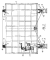
- the timing belt 20 is like the FIG. 2 shows, over all four gears 19 and further provided on the back of the fixed press plate 1 gears 21, 22, 23 and 24 stretched, of which the gear 23 by means of an electric motor, in particular by means of a servomotor, driven.
- the required tension in the toothed belt 20 can be adjusted so that the gear 24 by means of a pressure medium cylinder 25 is displaced.
- the four spindles 7 are moved in the same direction synchronously and - depending on the direction of rotation - advanced or withdrawn by the protective tubes 14, without turning, so that the movable press plate 2 is moved away from the fixed press plate 1 and moved towards it ,
- the movable press plate 2 slides on two guide rails 26, which are located on the base 3, and is supported by the four spindles 7.
- the movement of the movable press plate 2 is parallel to itself and parallel to the fixed press plate. 1
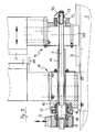
- FIG. 3 Notwithstanding the in FIG. 3 illustrated prior art is another arrangement of the front end of the spindle 7 on one of the lower spindle holders 10 and the overlying upper spindle holder 11 of the movable press plate 2 is provided in the apparatus according to the invention.
- the different attachment is in FIG. 4 illustrated by way of example for the lower spindle holder 10, but also applies in the same way for the overlying spindle holder 11.
- the spindles 7 according to FIG. 4 stored as well as it is based on the FIG. 3 is described, so that in the FIG. 4 does not have to be repeated.
- the front end 7a of the spindle 7 has been extended by an extension part 29 screwed onto the front end 7a.
- the extension part 29 consists of an internally threaded sleeve 30, which is rotated on the front end 7a of the spindle 7, and an extension 31 with an external thread.
- a threaded sleeve 32 is rotated until it stops, which surrounds the threaded sleeve 30.
- the threaded sleeve 32 is secured on the threaded extension 31 by a lock nut 13 and secured against rotation on a gear 33, via which a second toothed belt 34 runs.
- the outer ring 36 is fixedly connected to the spindle holder 10 and thereby with the movable press plate 2.
- the upper spindle 7, which is arranged above the extended lower spindle 7, 29, is extended and supported in a corresponding manner as in FIG FIG. 4 shown, extended, lower spindle 7, 29th
- the movable pressure plate 2 is moved forward or backward parallel to itself.
- the toothed belt 20 remains immobile and instead of the second toothed belt 34 is driven, then it rotates the gear 33 and, because this is rotatably connected to the spindle 7, 29, and the spindle 7, 29, so that these in the spindle nut 18th is shifted while taking the movable press plate 2.
- this displacement takes place only on the two elongated spindles 7, 29, but not in the other two, not elongated spindles 7, which as in FIG. 3 are shown represented.
- the second toothed belt 34 tensioned.
- the second toothed belt 34 is driven by a pressure medium cylinder 37, which has a continuous piston rod 38, whose two ends by means of fasteners 39 and 40 are attached to the two ends of the second toothed belt 34.
- the housing of the pressure medium cylinder 37 is fixed to frame parts 40 of the movable press plate 2 connected.
- a displacement sensor 41 is arranged, by means of which the displacement of the piston rod 38 is controlled.
- This is preferably a potentiometer-type displacement transducer in which a rod 42 connected to the piston rod 38 is displaceably mounted in the housing of the displacement transducer 41 and displaces an electrical potentiometer in accordance with its displacement.
- a clamping device 43 is fixed to the movable press plate 2, through which the toothed belt 34 passes. With the help of this clamping device 43, the second toothed belt 34 can be blocked, as long as it is not moved by the pressure medium cylinder 37. This can prevent the spindle 7 from rotating when the toothed belt 20 is driven.
- the fixed press plate 1 is formed as an air cushion wall, that is, it consists of a plate in which a number of holes is distributed, which can be supplied by a blower compressed air.
- a row of rollers 44 Below the fixed press plate is provided as a horizontal conveyor a row of rollers 44, whose axis is perpendicular to the press plate 1 and which are synchronously driven. Glass plates, which are to be assembled in the assembly device to an insulating glass, are supported on the roller line 44 and leaning against the fixed press plate 1 in the assembly device, wherein the emerging from the bores of the press plate 1 air between the press plate 1 and the glass sheet an air cushion on which slides the glass plate. This is well known to the person skilled in the art and therefore here not shown further.
- the movable press plate 2 is formed in a similar manner as the fixed press plate 1; it also has a number of holes distributed over its surface and communicating with a fan through which air can be drawn. Thereby, it is possible to suck a glass plate standing on the roller line 44 from the movable press plate 2 and then to remove it from the fixed press plate to make room for a subsequent glass plate, which positions the sucked by the movable press plate 2 glass plate opposite is to be able to assemble them into an insulating glass pane. This too is well known to the person skilled in the art and will not be described further here.
- the movable press plate 2 is provided at that vertical edge, which is adjacent to the non-extended spindles, with a bending device, which makes it possible to bend the suctioned there glass plate in the direction of the fixed press plate 1 away.
- a design of the press plate, with which this is possible, is described in detail in the EP 0 539 407 B1 described, which is hereby incorporated by reference; the in the EP 0 539 407 B1
- the disclosed construction of the bending device is suitable for the purposes of the present invention, so that this type of training has not been shown in the present drawings.
- FIG. 6 shows a first glass sheet 45 which abuts the fixed press plate 1 and is not bent. With her, the spacer frame 47 is glued, which is coated on both sides with a bead 48 of an adhesive. The second glass plate 46, which is sucked by the movable press plate 2, is at its one, in FIG.
- the assembly device according to the invention allows the following procedure:
- a first glass plate 46 is conveyed into the assembling device, stopped there, positioned, sucked by the movable press plate 2 and lifted from the fixed press plate 1.
- a second glass plate 45 already bonded to the spacer frame 47, is then fed into the assembly apparatus and positioned opposite the glass plate 46 against the stationary press plate. Then, the bender of the movable press plate 2 is activated and the first glass sheet 46 is bent along its one vertical edge. Then, when the toothed belt 20 is stopped, the pressure medium cylinder 37 is actuated, and thereby the movable pressure plate 2 by utilizing between the movable pressure plate 2 and the guide rails 26th existing game a little bit skewed.
- the toothed belt 20 can be kept at rest by an electric servomotor provided for its drive. The order of these two operations can also be reversed. Then the toothed belt 34 is clamped by the clamping device 34 and approximated by driving the toothed belt 20, the movable press plate 2 of the fixed press plate 1 until the glass plate 46 strikes the 48 coated with adhesive spacer frame 47, whereby the interior of the insulating glass to be formed except for in plan view, wedge-shaped gaps 49 and 50 are closed.
- the inclination of the movable press plate 2 can be 45 and 46 depending on the length of the glass plates are dimensioned so that the gap 50 has a width which is preferably not more than 1 mm.
- the opposite gap 49 produced by bending can be slightly wider, preferably 2 mm to 3 mm.
- a heavy gas is then introduced, in particular to the in the EP 0 539 407 B1 described way.
- the incoming heavy gas displaces the air mainly through the upper portion of the gap 49, partially through the opposite gap 50. If more heavy gas is introduced through the gap 49, as flows through the gap 50, the heavy gas rises in the insulating glass, which by sensors , which may be arranged along the gap 49, can be monitored. Report the sensors that the heavy gas has reached the top of the insulating glass, the filling process is terminated and the bending of the movable press plate 2 and thus the glass plate 46 reversed, so that the gap 49 closes.
- the movable press plate 2 is set by pressing the pressure medium cylinder 37 straight, the toothed belt 34 is clamped again by the clamping device 43 and then pressed by driving the toothed belt 20, the insulating glass pane between the two press plates 1 and 2 to its nominal size.
Abstract
Description
Die Erfindung geht aus von einer Vorrichtung zum Zusammenbauen von Glasplatten zu Isolierglasscheiben mit den im Oberbegriff des Anspruchs 1 angegebenen Merkmalen. Eine solche Vorrichtung ist aus der
Die Isolierglasscheibe kann Umgebungsluft enthalten, aber auch ein von Luft verschiedenes Gas, insbesondere ein Schwergas wie z.B. Argon. Die
Die bekannte Vorrichtung arbeitet in den hauptsächlichen Verwendungsfällen sehr zufriedenstellend. Bei langformatigen Isolierglasscheiben, deren Länge wesentlich größer ist als ihre Höhe, wird es jedoch mit zunehmender Länge schwieriger, die Luft aus dem von der Gaszuführeinrichtung weit entfernten Abschnitt der Isolierglasscheibe zu verdrängen, so daß es mit zunehmender Länge der Isolierglasscheiben schwieriger wird, einen angestrebten Füllgrad von mehr als 90 Volumen-% oder von mehr als 95 Volumen% innerhalb der üblichen Taktzeit einer Isolierglasfertigungslinie von nicht mehr als ca. 20 Sekunden zu erreichen. Das gilt insbesondere dann, wenn die Gasströmung in der Isolierglasscheibe noch durch eingebaute Sprossen behindert wird.The known device works very satisfactorily in the main use cases. With long-sized insulating glass panes whose length is substantially greater than their height, however, it becomes more difficult with increasing length to displace the air from the portion of the insulating glass pane far away from the gas supply means, so that with increasing length of the insulating glass panes, a desired degree of filling becomes more difficult of more than 90% by volume or more than 95% by volume within the usual cycle time of an insulating glass production line of not more than about 20 seconds. This is especially true when the gas flow in the insulating glass is obstructed by built-in rungs.
Der vorliegenden Erfindung liegt die Aufgabe zugrunde, einen Weg aufzuzeigen, wie bei einer Zusammenbauvorrichtung der in der
Diese Aufgabe wird gelöst durch eine Vorrichtung mit den im Anspruch 1 angegebenen Merkmalen. Vorteilhafte Weiterbildungen der Erfindung sind Gegenstand der Unteransprüche.This object is achieved by a device having the features specified in
Die erfindungsgemäße Zusammenbauvorrichtung zeichnet sich durch die kennzeichnenden Merkmale des Anspruchs 1 aus. Das erlaubt es, die bewegliche Preßplatte nicht nur parallel zur feststehenden Preßplatte zu bewegen, sondern sie demgegenüber auch ein wenig schrägzustellen. Das soll mit den beiden Verstelleinrichtungen geschehen, welche von der Biegeeinrichtung der beweglichen Preßplatte weiter entfernt liegen als die anderen beiden Verstelleinrichtungen. Damit ist es möglich, die zusammenzubauende Isolierglasscheibe nicht nur an dem einen Rand, an welchem die Glasplatte gebogen werden kann, sondern auch am gegenüberliegenden Rand etwas offen zu halten, nämlich durch die leichte Schrägstellung der beiden Preßplatten zueinander, so daß bei langformatigen Isolierglasscheiben ein durch Biegen erzeugter Spalt an dem einen von oben nach unten verlaufenden Rand vorgesehen ist, während ein durch Schrägstellung der Preßplatte gebildeter zweiter Spalt am gegenüberliegenden Rand gebildet werden kann und in dem dazwischenliegenden Abschnitt die gebogene Glasplatte bereits mit dem Rahmen vom Abstandhalter verklebt ist. Am einen Rand der Isolierglasscheibe einströmendes Gas kann deshalb die Luft aus der Isolierglasscheibe nicht nur durch den oberen Abschnitt desselben Randes verdrängen, sondern auch durch den gegenüberliegenden Spalt, so daß das Schwergas mit Leichtigkeit auch den der Gaszuführeinrichtung entfernt gegenüberliegenden Abschnitt der Isolierglasscheibe erreicht. Dabei hält man den durch Schrägstellen erzeugten Spalt vorzugsweise schmaler als den durch Biegen erzeugten Spalt, weil das im Hinblick auf die auftretenden Schwergasverluste günstiger ist. Der durch das Schrägstellen erzeugte Spalt sollte höchstens 1 mm breit sein, günstig ist eine Breite von 0,5 mm bis 1 mm. Für den durch Biegen erzeugten Spalt hat sich demgegenüber eine Breite von 2 mm bis 3 mm bewährt. Trotz der Gasverluste, die durch Austreten von Schwergas aus dem durch Schrägstellen der beweglichen Preßplatte gebildeten Spalt auftreten, kann das Schwergas zügig im Innenraum der Isolierglasscheibe hochsteigen, wenn es mit höherem Durchsatz eingefüllt wird, als es entweichen kann, was sich, wie sich gezeigt hat, problemlos erreichen läßt. Im Ergebnis kann man auch bei sehr langformatigen Isolierglasscheiben hohe Füllgrade von mehr als 90 % innerhalb von weniger als 20 Sekunden bei wirtschaftlich vertretbaren Gasverlusten erreichen. Die auftretenden Gasverluste werden mehr als überkompensiert dadurch, daß die Füllzeit und damit die Produktivität der Isolierglasfertigungslinie erhöht wird, wobei ein besonderer Vorteil noch darin liegt, daß dies mit einem minimalen Aufwand für die Abänderung einer herkömmlichen Zusammenbauvorrichtung erreichbar ist.The assembly device according to the invention is characterized by the characterizing features of
Die Einrichtungen zum Biegen der Glasplatte und zum Zuführen von Schwergas können so ausgebildet sein, wie es in der
Die Verstelleinrichtungen, um die bewegliche Preßplatte im Abstand gegenüber der feststehenden Preßplatte zu verändern, können Druckmittelzylinder sein, welche nahe bei den vier Ecken der Preßplatten angreifen und die Preßplatten miteinander verbinden. Besonders bevorzugt sind jedoch Verstelleinrichtungen, welche mit einer Spindel arbeiten, wobei jeweils eine Spindel in der Nachbarschaft einer Ecke der Preßplatten angeordnet ist und die Spindeln an der einen Preßplatte festgelegt sind und an der anderen Preßplatte in einer dort vorgesehenen Spindelmutter stecken, wobei entweder die Spindeln drehbar an die Spindelmuttern fest angeordnet sind oder die Spindelmuttern fest angeordnet sind und die Spindeln drehbar gelagert sind. Mit spielarmen Spindeln, z.B. mit Kugelumlaufspindeln, läßt sich die bewegliche Preßplatte präzise bewegen. Zur Synchronisierung der vier Spindeln haben sie vorzugsweise einen gemeinsamen ersten Antrieb, vorzugsweise mit Hilfe eines endlosen Zahnriemens, welcher durch einen Motor, insbesondere durch einen elektrischen Servomotor, angetrieben wird und über Zahnräder gespannt ist, welche im Falle von drehbaren Spindelmuttern mit diesen verbunden sind bzw. im Falle von drehbaren Spindeln mit jenen verbunden sind.The adjusting means for varying the movable pressure plate at a distance from the fixed pressure plate may be pressure medium cylinders which engage close to the four corners of the pressure plates and connect the pressure plates together. However, particularly preferred are adjusting means which operate with a spindle, wherein in each case a spindle is arranged in the vicinity of a corner of the press plates and the spindles are fixed to the one press plate and stuck to the other press plate in a spindle nut provided there, either the spindles are rotatably fixed to the spindle nuts or the spindle nuts are fixed and the spindles are rotatably mounted. With low-backlash spindles, e.g. with ball screws, the movable pressure plate can be moved precisely. To synchronize the four spindles, they preferably have a common first drive, preferably by means of an endless toothed belt, which is driven by a motor, in particular by an electric servomotor, and is tensioned via toothed wheels, which in the case of rotatable spindle nuts are connected to these or in the case of rotatable spindles are connected to those.
Die beiden Verstelleinrichtungen, welche es ermöglichen stollen, die bewegliche Preßplatte schrägzustellen können zusätzlich einzeln betätigbar sein. Es könnten z.B. kurzhubige Druckmittelzylinder sein, die unter Ausnutzung eines Führungsspiels der beweglichen Preßplatte eine geringe Schrägstellung bewirken. Vorzugsweise werden jedoch die ohnehin vorgesehenen Verstelleinrichtungen herangezogen, um auch eine Schrägstellung zu bewirken.The two adjusting devices which make it possible to incline the movable press plate can additionally be actuated individually. It could be, for example, short-stroke pressure cylinder, which cause a slight inclination taking advantage of a guide clearance of the movable press plate. Preferably, however, the adjusting devices provided anyway are used in order to also effect an inclination.
Sind für den ersten Antrieb Spindeln vorgesehen, die in Spindelmuttern stecken, welche über einen Zahnriemen antreibbar sind, dann wird es bevorzugt, die beiden getrennt betätigbaren Spindeln auf jener Seite der anderen Preßplatte, welche den Zahnrädern des ersten Antriebes abgewandt ist, verdrehfest mit weiteren zwei Zahnrädern zu verbinden, über welche ein zweiter Zahnriemen gespannt ist, welcher einem zweiten Antrieb angehört, mit welchem nur diese beiden zwei weiteren Zahnräder angetrieben werden können, um die bewegliche Preßplatte schrägzustellen. Das erfolgt dadurch, daß in diesem Fall der zweite Zahnriemen die beiden betreffenden Spindeln dreht, so daß sie sich in den Spindelmuttern verlagern, die während dessen stillstehen, indem der erste Antrieb in Ruhe verharrt. Wenn hingegen der erste Antrieb betätigt wird, soll der zweite Antrieb in Ruhe verharren, damit sich die Spindeln nicht mitdrehen, wenn die Spindelmuttern angetrieben werden. Zu diesem Zweck ist es bevorzugt, den zweiten Zahnriemen durch eine Klemmeinrichtung hindurchzuführen, die nach Bedarf klemmen und dadurch den zweiten Antrieb blockieren kann.Spindles are provided for the first drive, which are in spindle nuts, which are driven by a toothed belt, then it is preferred, the two separately operable spindles on that side of the other press plate, which is remote from the gears of the first drive, rotationally fixed with another two To connect gears over which a second toothed belt is tensioned, which belongs to a second drive, with which only these two other two gears can be driven to tilt the movable pressure plate. This is done in that case in this case, the second toothed belt rotates the two respective spindles, so that they shift in the spindle nuts, which are resting during which by the first drive remains at rest. If, on the other hand, the first drive is actuated, the second drive should remain at rest, so that the spindles do not rotate when the spindle nuts are driven. For this purpose, it is preferable to pass the second toothed belt through a clamping device which can clamp as required and thereby block the second drive.
Sind hingegen die Zahnräder des ersten Antriebes verdrehfest mit den Spindeln verbunden und statt dessen die Spindelmuttern unverdrehbar gelagert, dann kann man den beiden gesondert anzutreibenden Spindeln auf der Außenseite der den Zahnrädern des ersten Antriebes abgewandten Preßplatte jeweils eine Spindelmutter zuordnen, welche verdrehfest mit jeweils einem weiteren Zahnrad verbunden ist, über welches dann der zweite Zahnriemen gespannt wird. Der Unterschied zur vorhergehend beschriebenen Ausführungsform besteht lediglich darin, daß im einen Fall der erste Antrieb die Spindelmuttern treibt, während er im anderen Fall die Spindeln treibt.If, however, the gears of the first drive rotationally connected to the spindles and instead the spindle nuts mounted non-rotatably, then you can assign the two separately driven spindles on the outside of the gears of the first drive facing away from each press plate a spindle nut which rotationally with one another Gear is connected, via which then the second toothed belt is tensioned. The difference to the previously described embodiment is only that in one case, the first drive drives the spindle nuts, while in the other case drives the spindles.
Eine andere Möglichkeit, die bewegliche Preßplatte schrägzustellen, besteht darin, die beiden betreffenden Spindeln mittels zweier zusätzlicher elektrischer Servomotoren anzutreiben, mit welchen die beiden Spindeln einzeln, vorzugsweise synchron, verstellt werden können.Another way to tilt the movable press plate, is to drive the two spindles concerned by means of two additional electric servomotors, with which the two spindles individually, preferably synchronously, can be adjusted.
Ein Vorteil der Erfindung liegt darin, daß er für den zweiten Antrieb Bauelemente verwenden kann, die auch schon für den ersten Antrieb Verwendung gefunden haben. Das macht die erfindungsgemäße Ausbildung der Zusammenbauvorrichtung sehr preiswert. Es ist weiterhin möglich, vorhandene Zusammenbauvorrichtungen erfindungsgemäß mit geringem Aufwand nachzurüsten, indem bei ihnen zwei Spindeln durch Verlängerungsstücke verlängert werden, an welchen man einen zweiten Antrieb angreifen läßt.An advantage of the invention is that it can use components for the second drive, which have already found use for the first drive. This makes the inventive design of the assembly device very inexpensive. It is also possible to retrofit existing assembly devices according to the invention with little effort by their two spindles are extended by extension pieces, where you can attack a second drive.
Der zweite Zahnriemen könnte durch einen elektrischen Servomotor angetrieben werden. Einfacher ist es, ihn mittels eines Druckmittelzylinders anzutreiben, welcher eine durchgehende Kolbenstange hat, deren zwei Enden mit den beiden Enden des zweiten Zahnriemens verbunden sind. Bei geeignetem Untersetzungsverhältnis vom Druckmittelzylinder zum Zahnrad und vom Zahnrad zur Spindel kann man so die bewegliche Preßplatte feinfühlig ein wenig schrägstellen, wobei das vorzugsweise unter der Kontrolle eines Wegaufnehmers geschieht, welcher die Verschiebebewegung der Kolbenstange überwacht.The second toothed belt could be driven by an electric servomotor. It is simpler to drive it by means of a pressure medium cylinder, which has a continuous piston rod whose two ends are connected to the two ends of the second toothed belt. With a suitable reduction ratio of the pressure cylinder to the gear and the gear to the spindle so you can sensitively tilt the movable pressure plate a little, which is preferably done under the control of a Wegaufnehmers, which monitors the displacement movement of the piston rod.
Bei der aus der
Ein bevorzugtes Ausführungsbeispiel der Erfindung wird anhand der beigefügten Zeichnungen erläutert.
Figur 1- zeigt eine Vorrichtung zum Zusammenbauen von Isolierglasscheiben in einer Seitenansicht,
Figur 2- zeigt die Vorrichtung aus
Figur 1 Figur 3- zeigt als Detail einen Querschnitt durch die Vorrichtung im Bereich einer der unteren Verstelleinrichtungen gemäß Schnittlinie A-A in
Figur 2, jedoch mit einer Ausbildung der Verstelleinrichtung wie im Stand der Technik, - Figur 4
- zeigt einen Schnitt wie in
Figur 3 Figur 5- zeigt eine teilweise Vorderansicht der Vorrichtung, und
- Figur 6
- zeigt schematisch einen Horizontalschnitt durch eine halbfertig zusammengebaute Isolierglasscheibe während des Zusammenbaus in der erfindungsgemäßen Vorrichtung gemäß
den Figuren 1 ,2 ,4 und 5 .
- FIG. 1
- shows a device for assembling insulating glass panes in a side view,
- FIG. 2
- shows the device
FIG. 1 in a view on the back, - FIG. 3
- shows in detail a cross section through the device in the region of one of the lower adjustment devices according to section line AA in Figure 2, but with an embodiment of the adjusting device as in the prior art,
- FIG. 4
- shows a cut as in
FIG. 3 by the device further developed according to the invention, - FIG. 5
- shows a partial front view of the device, and
- FIG. 6
- schematically shows a horizontal section through a semi-assembled insulating glass pane during assembly in the inventive device according to the
FIGS. 1 .2 .4 and5 ,
Die Zusammenbauvorrichtung hat eine feststehende ebene Preßplatte 1 und eine ihr gegenüberliegende bewegliche, ebene Preßplatte 2, welche in einer ungefähr 6° nach hinten geneigten Lage auf einem Sockel 3 stehen. Die feststehende Preßplatte 1 ist rückseitig durch zwei Streben 4 abgestützt, welche einerseits an Laschen 5, welche sich im oberen Bereich der Preßplatte 1 befinden, und andererseits an Laschen 6 gelenkig befestigt sind, welche sich im hinteren Bereich des Sockels 3 befinden. In
Die beiden Preßplatten 1 und 2 sind durch vier zueinander parallele Spindeln 7 miteinander verbunden. Zu diesem Zweck sind am unteren Rand der feststehenden Preßplatte 1 zwei Spindelhalterungen 8, am oberen Rand der feststehenden Preßplatte 1 zwei Spindelhalterungen 9, am unteren Rand der beweglichen Preßplatte 2 zwei Spindelhalterungen 10 und am oberen Rand der beweglichen Preßplatte 2 zwei Spindelhalterungen 11 angebracht. Bei einer herkömmlichen Zusammenbauvorrichtung ist die Spindel 7, wie in
Gemäß
Die oberen Spindeln 7 befinden sich mit ihrem von der Rückseite der feststehenden Preßplatte 1 nach hinten ragenden Abschnitt in einem weiteren Schutzrohr 27. Die unteren Spindeln 7 erstrecken sich mit ihrem von der Rückseite der feststehenden Platte 1 nach hinten ragenden Abschnitt in ein Schutzgehäuse 28, welches sich auf dem Sockel 3 befindet.The
An der Rückseite der Spindelhalterung 8 befindet sich eine Montageplatte 15, mit welcher der Außenring 16 eines Kugellagers 17 fest verschraubt ist. In den drehbaren Innenring des Kugellagers 17 ist eine Spindelmutter 18 eingesetzt, welche verdrehfest mit einem Zahnrad 19 verbunden, insbesondere verschraubt ist, über welches ein endloser Zahnriemen 20 läuft. In entsprechender Weise sind die beiden oberen Spindeln 7 in den oberen Spindelhalterungen 9 der feststehenden Preßplatte 1 gelagert.At the back of the
Der Zahnriemen 20 ist, wie die
Abweichend von dem in
Erfindungsgemäß ist das vordere Ende 7a der Spindel 7 durch ein auf das vordere Ende 7a aufgeschraubtes Verlängerungsteil 29 verlängert worden. Das Verlängerungsteil 29 besteht aus einer mit Innengewinde versehenen Hülse 30, welche auf das vordere Ende 7a der Spindel 7 gedreht ist, und aus einem Fortsatz 31 mit einem Außengewinde. Auf diesen Gewindefortsatz 31 ist bis zum Anschlag eine Gewindehülse 32 gedreht, welche die Gewindehülse 30 umschließt. Die Gewindehülse 32 ist auf dem Gewindefortsatz 31 durch eine Kontermutter 13 gesichert und verdrehfest an einem Zahnrad 33 befestigt, über welches ein zweiter Zahnriemen 34 läuft. Außerdem sitzt auf der Gewindehülse 32 der Innenring eines Kugellagers 35, dessen Außenring 36 fest mit der Spindelhalterung 10 und dadurch mit der beweglichen Preßplatte 2 verbunden ist. Jene obere Spindel 7, welche über der verlängerten unteren Spindel 7, 29 angeordnet ist, ist in entsprechender Weise verlängert und gelagert wie die in
Solange der zweite Zahnriemen 34 unbeweglich verharrt, wird durch Antreiben des Zahnriemens 20 die bewegliche Preßplatte 2 parallel zu sich selbst vor- oder zurückbewegt. Verharrt jedoch der Zahnriemen 20 unbeweglich und wird statt dessen der zweite Zahnriemen 34 angetrieben, dann verdreht er das Zahnrad 33 und, weil dieses drehfest mit der Spindel 7, 29 verbunden ist, auch die Spindel 7, 29, so daß diese in der Spindelmutter 18 verlagert wird und dabei die bewegliche Preßplatte 2 mitnimmt. Diese Verlagerung findet jedoch nur an den beiden verlängerten Spindeln 7, 29 statt, nicht aber bei den beiden anderen, nicht verlängerten Spindeln 7, welche wie in
Außerdem ist an der beweglichen Preßplatte 2 noch eine Klemmeinrichtung 43 befestigt, durch welche der Zahnriemen 34 hindurchläuft. Mit Hilfe dieser Klemmeinrichtung 43 kann der zweite Zahnriemen 34 blockiert werden, solange er nicht durch den Druckmittelzylinder 37 bewegt wird. Dadurch kann verhindert werden, daß sich die Spindel 7 dreht, wenn der Zahnriemen 20 angetrieben wird.In addition, a
Anstatt die beiden Zahnräder 33 durch einen in den Zahnriemen 34 integrierten Druckmittelzylinder 37 anzutreiben, könnte man sie auch einzeln, vorzugsweise synchron, durch je einen zusätzlichen elektrischen Servomotor antreiben.Instead of driving the two
Die feststehende Preßplatte 1 ist als Luftkissenwand ausgebildet, daß heißt, sie besteht aus einer Platte, in welcher eine Anzahl von Bohrungen verteilt ist, welchen durch ein Gebläse Druckluft zugeführt werden kann. Unterhalb der feststehenden Preßplatte ist als Waagerechtförderer eine Zeile von Rollen 44 vorgesehen, deren Achse senkrecht zur Preßplatte 1 verläuft und welche synchron antreibbar sind. Glasplatten, welche in der Zusammenbauvorrichtung zu einer Isolierglasscheibe zusammengebaut werden sollen, werden auf der Rollenzeile 44 stehend und gegen die feststehende Preßplatte 1 gelehnt in die Zusammenbauvorrichtung gefördert, wobei die aus den Bohrungen der Preßplatte 1 austretende Luft zwischen der Preßplatte 1 und der Glastafel ein Luftkissen bildet, auf welchem die Glasplatte gleitet. Dies ist dem Fachmann gut bekannt und deshalb hier nicht weiter dargestellt. Die bewegliche Preßplatte 2 ist in ähnlicher Weise ausgebildet wie die feststehende Preßplatte 1; sie weist ebenfalls eine Anzahl von Bohrungen auf, welche über ihre Fläche verteilt sind und mit einem Gebläse in Verbindung stehen, durch welches Luft angesaugt werden kann. Dadurch ist es möglich, eine auf der Rollenzeile 44 stehende Glasplatte von der beweglichen Preßplatte 2 ansaugen zu lassen und dann von der feststehenden Preßplatte zu entfernen, um dort Platz zu machen für eine nachfolgende Glasplatte, welche der von der beweglichen Preßplatte 2 angesaugten Glasplatte gegenüberliegend positioniert wird, um sie zu einer Isolierglasscheibe zusammenbauen zu können. Auch das ist dem Fachmann gut bekannt und wird hier nicht weiter beschrieben.The fixed
Die bewegliche Preßplatte 2 ist an jenem vertikalen Rand, welcher den nicht verlängerten Spindeln benachbart ist, mit einer Biegeeinrichtung versehen, welche es ermöglicht, die dort angesaugte Glasplatte in Richtung von der feststehenden Preßplatte 1 weg zu biegen. Eine Ausbildung der Preßplatte, mit welcher das möglich ist, ist ausführlich in der
Eine erfindungsgemäße ausgebildete Zusammenbauvorrichtung erlaubt es, an dem anderen vertikalen Rand der zusammenzubauenden Isolierglasscheibe ebenfalls einen Spalt offenzuhalten, während die beiden Glasplatten 45 und 46 über den Abstandhalterrahmen 47 längs ihrer horizontalen Ränder bis auf die Spalte an den vertikalen Rändern bereits miteinander verklebt sind, wie es schematisch, jedoch übertrieben, in
Die erfindungsgemäße Zusammenbauvorrichtung erlaubt folgende Arbeitsweise:The assembly device according to the invention allows the following procedure:
Eine erste Glasplatte 46 wird in die Zusammenbauvorrichtung gefördert, dort angehalten, positioniert, von der beweglichen Preßplatte 2 angesaugt und von der feststehenden Preßplatte 1 abgehoben. Eine zweite Glasplatte 45, welche bereits mit dem Abstandhalterrahmen 47 verklebt ist, wird anschließend in die Zusammenbauvorrichtung gefördert und der Glasplatte 46 gegenüberliegend an der feststehenden Preßplatte positioniert. Dann wird die Biegeeinrichtung der beweglichen Preßplatte 2 aktiviert und die erste Glastafel 46 längs ihres einen vertikalen Randes gebogen. Dann wird bei stillstehendem Zahnriemen 20 der Druckmittelzylinder 37 betätigt und dadurch die bewegliche Preßplatte 2 unter Ausnutzung des zwischen der beweglichen Preßplatte 2 und den Führungsschienen 26 vorhandenen Spiels ein wenig schräggestellt. Dabei kann der Zahnriemen 20 durch einen zu seinem Antrieb vorgesehenen elektrischen Servomotor in Ruhe gehalten werden. Die Reihenfolge dieser beiden Vorgänge kann auch vertauscht werden. Dann wird der Zahnriemen 34 durch die Klemmeinrichtung 34 festgeklemmt und durch Antreiben des Zahnriemens 20 die bewegliche Preßplatte 2 der feststehenden Preßplatte 1 angenähert, bis die Glasplatte 46 auf den mit Klebstoff 48 beschichteten Abstandhalterrahmen 47 trifft, wodurch der Innenraum der zu bildenden Isolierglasscheibe bis auf die in der Draufsicht keilförmigen Spalte 49 und 50 geschlossen wird. Die Schrägstellung der beweglichen Preßplatte 2 kann dabei in Abhängigkeit von der Länge der Glasplatten 45 und 46 so bemessen werden, daß der Spalt 50 eine Breite hat, welche vorzugsweise nicht mehr als 1 mm beträgt. Der durch das Biegen erzeugte gegenüberliegende Spalt 49 kann demgegenüber etwas breiter sein, vorzugsweise 2 mm bis 3 mm. Im unteren Bereich des Spaltes 49 wird dann ein Schwergas eingeleitet, insbesondere auf die in der
Trotz der beim Gasaustausch auftretenden Gasverluste durch den Spalt 50 hat es sich gezeigt, daß langformatige Isolierglasscheiben selbst dann, wenn die Gasströmung in ihnen durch eingebaute Sprossen behindert wird, innerhalb der typischen Zykluszeit einer Isolierglasfertigungslinie von weniger als 20 Sekunden mit Füllgraden von mehr als 90 % gefüllt werden können. Die durch den Spalt 50 auftretenden Gasverluste sind hinnehmbar, weil es die erfindungsgemäße Weiterbildung einer Zusammenbauvorrichtung gemäß der
Claims (19)
- Device for assembling insulating glass panes from glass plates (45, 46) that are held at a distance, and are bonded one to the other along their edges, via a frame-like spacer (47), comprising
a first upright, substantially rectangular pressing plate (1),
a horizontal conveyor (44) arranged below the first pressing plate (1), on which the glass plates (45, 46) are placed in upright position and can be conveyed into the device, supported by the first pressing plate (1),
a second substantially rectangular pressing plate (2), which is arranged in parallel to the first pressing plate (1) and at a variable distance to the latter and which is provided with means by which a glass plate (46) can be attached to it by suction and, along one of its two edges that extend from the bottom to the top, with a device for temporarily bending the glass plate (46) that has been attached to it by suction,
the pressing plates (1, 2) being connected one with the other in the neighborhood of their four corners by adjusting means that serve to vary their spacing, and means being provided for synchronizing the adjusting means, characterized in that the device additionally comprises means through which those lower adjusting means and the upper adjusting means arranged above the latter, which are farther remote than the other two adjusting devices from the device for temporarily bending the glass plate (46) attached to the second pressing plate (2) by suction, can additionally be operated separately from the two other adjusting means. - The device as defined in Claim 1, characterized in that the adjusting means are pneumatic cylinders.
- The device as defined in Claim 1, characterized in that each adjusting device comprises a spindle (7) as the adjusting element that connects the pressing plates (1, 2) one with the other, as well as a spindle nut (18) that coacts with the spindle (7).
- The device as defined in any of the preceding claims, characterized in that the four adjusting means have a common first drive (19 to 25).
- The device as defined in Claim 3 and Claim 4, characterized in that for forming the first drive the spindles (7) or the spindle nuts (18) are each non-torsionally connected with a gear (19) that meshes with an endless toothed belt (20) or a chain, the gears (19) being arranged either at the back of the first pressing plate or at the back of the second pressing plate.
- The device as defined in any of the preceding claims, characterized in that said two adjusting means, which can be operated separately from the other adjusting means, each comprise a servomotor.
- The device as defined in Claim 6, characterized in that the two servomotors are synchronized one with the other.
- The device as defined in any of Claims 1 to 5, characterized in that said two adjusting means that can be operated separately one from the other have a common second drive (33, 34, 37 to 42).
- The device as defined in any of Claims 4 to 8, characterized in that the first and the second drives can be operated and blocked individually.
- The device as defined in Claim 5 in combination with any of Claims 6 to 9, wherein the gears (19) of the first drive are non-torsionally connected with the spindle nuts (18) characterized in that the two separately operable spindles (7, 29) are non-torsionally connected, on the side of the other pressing plate (2) that faces away from the gears (19) of the drive, with two further gears (33) that mesh with a second toothed belt (34) that belongs to the second drive.
- The device as defined in Claim 5 in combination with any of Claims 6 to 9, wherein each of the four gears (19) belonging to the first drive is non-torsionally connected with one of the spindles (7), characterized in that a spindle nut is arranged on each of the two spindles (7, 29) that are to be driven separately, on the outside of the pressing plate (2) that faces away from the gears (19) of the first drive, which spindle nuts are each non-torsionally connected with a further gear, and that those two further gears mesh with a second toothed belt.
- The device as defined in Claim 10 or Claim 11, characterized in that the second toothed belt (34) is driven via a pneumatic cylinder (37) that has a passing piston rod (38) the two ends of which are connected with the two ends of the second toothed belt (34).
- The device as defined in Claim 12, characterized in that a position encoder (41) is associated with the pneumatic cylinder (37) for monitoring the displacing movement of the piston rod (38).
- The device as defined in any of the preceding claims, characterized in that two parallel guide rails are provided on the base (3) on which the movable pressing plate (2) slides via suitable sliding blocks (51).
- The device as defined in Claim 14, characterized in that the sliding blocks (51) are connected with the movable pressing plate (2) in articulated fashion.
- The device as defined in any of the preceding claims, characterized in that a bending device, which serves to bend the glass plate (46) located on the respective pressing plate, is provided at that end of the stationary pressing plate (1) or - preferably - of the movable pressing plate (2) which is farther remote from the separately operable adjusting means, whereby that glass plate is bent away from the oppositely arranged pressing plate.
- The device as defined in Claim 16, characterized in that means for supplying a gas different from air are provided at the same side on the assembly device, especially in the lower region of the pressing plates (1, 2).
- The device as defined in Claim 16 or Claim 17, characterized in that the means for bending the pressing plate (46) are configured in the way disclosed in EP 0 539 407 B1.
- The device as defined in any of Claims 16 to 18, characterized in that the means for supplying a gas different from air are configured in the way disclosed in EP 0 539 407 B1.
Applications Claiming Priority (3)
| Application Number | Priority Date | Filing Date | Title |
|---|---|---|---|
| DE10138346A DE10138346C2 (en) | 2001-08-03 | 2001-08-03 | Device for assembling insulating glass panes |
| DE10138346 | 2001-08-03 | ||
| PCT/EP2002/008269 WO2003014511A1 (en) | 2001-08-03 | 2002-07-25 | Device for assembling insulating glass panes |
Publications (2)
| Publication Number | Publication Date |
|---|---|
| EP1412604A1 EP1412604A1 (en) | 2004-04-28 |
| EP1412604B1 true EP1412604B1 (en) | 2009-08-12 |
Family
ID=7694413
Family Applications (1)
| Application Number | Title | Priority Date | Filing Date |
|---|---|---|---|
| EP02754936A Expired - Lifetime EP1412604B1 (en) | 2001-08-03 | 2002-07-25 | Device for assembling insulating glass panes |
Country Status (4)
| Country | Link |
|---|---|
| EP (1) | EP1412604B1 (en) |
| AT (1) | ATE439503T1 (en) |
| DE (2) | DE10138346C2 (en) |
| WO (1) | WO2003014511A1 (en) |
Cited By (2)
| Publication number | Priority date | Publication date | Assignee | Title |
|---|---|---|---|---|
| DE102010045954A1 (en) * | 2010-09-21 | 2012-03-22 | Bystronic Armatec Gmbh | Composite glass press for laminating a glass package to produce a laminated safety glass, includes upper and lower pressure rollers, and first and second spindle drives arranged on a front side and on corrugated ends of the pressure roller |
| US8821662B2 (en) | 2010-09-23 | 2014-09-02 | Lisec Austria Gmbh | Method for producing insulating glass that is filled with a gas that is different from air |
Families Citing this family (5)
| Publication number | Priority date | Publication date | Assignee | Title |
|---|---|---|---|---|
| DE102009048641B4 (en) * | 2009-09-30 | 2014-02-06 | Bystronic Lenhardt Gmbh | Method for assembling a window sash with integrated insulating glass pane |
| DE102009048642B4 (en) * | 2009-09-30 | 2013-07-04 | Bystronic Lenhardt Gmbh | Device for assembling a window sash with integrated insulating glass pane |
| DE102015005612A1 (en) | 2015-04-30 | 2016-11-03 | Lisec Austria Gmbh | Assembly press and method for manufacturing insulating glass elements |
| DE102015118960A1 (en) | 2015-08-21 | 2017-02-23 | Bystronic Lenhardt Gmbh | Method and apparatus for assembling glass panels to insulating glass panes |
| EP3133234A1 (en) | 2015-08-21 | 2017-02-22 | Bystronic Lenhardt GmbH | Method and device for joining sheets of glass to form insulating glass panes |
Family Cites Families (4)
| Publication number | Priority date | Publication date | Assignee | Title |
|---|---|---|---|---|
| DE58900360D1 (en) * | 1988-05-04 | 1991-11-14 | Lenhardt Maschinenbau | METHOD AND DEVICE FOR FILLING INSULATING GLASS DISCS WITH A HEAVY GAS. |
| DE4022185A1 (en) * | 1990-07-13 | 1992-01-16 | Lenhardt Maschinenbau | METHOD AND DEVICE FOR ASSEMBLING INSULATING GLASS PANELS FILLED WITH A GAS DIFFERENT FROM AIR |
| DE4212256C2 (en) * | 1992-04-11 | 1998-06-04 | Lenhardt Maschinenbau | Device for assembling two insulating glass panes which are filled with a gas other than air |
| DE20113608U1 (en) * | 2001-08-03 | 2002-01-10 | Lenhardt Maschinenbau | Device for assembling insulating glass panes |
-
2001
- 2001-08-03 DE DE10138346A patent/DE10138346C2/en not_active Withdrawn - After Issue
-
2002
- 2002-07-25 AT AT02754936T patent/ATE439503T1/en active
- 2002-07-25 DE DE50213767T patent/DE50213767D1/en not_active Expired - Lifetime
- 2002-07-25 WO PCT/EP2002/008269 patent/WO2003014511A1/en active Application Filing
- 2002-07-25 EP EP02754936A patent/EP1412604B1/en not_active Expired - Lifetime
Cited By (3)
| Publication number | Priority date | Publication date | Assignee | Title |
|---|---|---|---|---|
| DE102010045954A1 (en) * | 2010-09-21 | 2012-03-22 | Bystronic Armatec Gmbh | Composite glass press for laminating a glass package to produce a laminated safety glass, includes upper and lower pressure rollers, and first and second spindle drives arranged on a front side and on corrugated ends of the pressure roller |
| DE102010045954B4 (en) * | 2010-09-21 | 2017-12-14 | Armatec GmbH | Laminated glass roller press |
| US8821662B2 (en) | 2010-09-23 | 2014-09-02 | Lisec Austria Gmbh | Method for producing insulating glass that is filled with a gas that is different from air |
Also Published As
| Publication number | Publication date |
|---|---|
| DE10138346A1 (en) | 2003-04-24 |
| DE50213767D1 (en) | 2009-09-24 |
| WO2003014511A1 (en) | 2003-02-20 |
| ATE439503T1 (en) | 2009-08-15 |
| EP1412604A1 (en) | 2004-04-28 |
| DE10138346C2 (en) | 2003-12-04 |
Similar Documents
| Publication | Publication Date | Title |
|---|---|---|
| DE102010035748B4 (en) | Method for assembling insulating glass panes, which have three glass plates parallel to each other | |
| DE3101342A1 (en) | "METHOD FOR PRODUCING GAS-FILLED INSULATING GLASS UNITS AND DEVICE FOR IMPLEMENTING THE METHOD" | |
| EP1730378A2 (en) | Method for positioning sheets of glass in a vertical assembly and press device for insulating glass panes | |
| DE102005044861B3 (en) | Filling insulation glass disks method e.g. for gas different from air, involves filling two glass tablets with different gas, in device having two opposite plates and parallel plates are mutually variable in distance to each other | |
| EP1412604B1 (en) | Device for assembling insulating glass panes | |
| DE102005033040B3 (en) | Apparatus for assembling insulating glass panes filled with a gas other than air | |
| DE2413398C3 (en) | Pneumatically or hydraulically operated frame press for window frames with associated casement for windows or the like. | |
| DE102015118960A1 (en) | Method and apparatus for assembling glass panels to insulating glass panes | |
| DE2821104B2 (en) | Device for the production of an insulating glass pane with a support device for at least one pane and with a pressing device which can be raised and lowered parallel to the support device and has an adjustable contact force | |
| DE102007062386A1 (en) | Teigbearbeitungsanlage | |
| DE2546304A1 (en) | Plant for production of double glazed window frames - is line traversed by vertical panes and mounting and assembly mechanisms retract from line | |
| DE19642930B4 (en) | Device for bending or bending hollow profile strips | |
| EP0579593A1 (en) | Device for fabricating spacing frames out of hollow section strips for insulating glass panes | |
| EP0100065A2 (en) | Automatic drilling and milling machine | |
| EP0585613A1 (en) | Sheet rolling machine | |
| DE102009030145A1 (en) | Table i.e. vacuum clamping table, for fitting plate shaped-article on surface, has stroke elements moving upward during raising of elements from slots such that plate-shaped article lying on table surface is supported by elements | |
| DE3246893A1 (en) | Pneumatically or hydraulically operable frame press | |
| DE3400031C1 (en) | Device for conveying panes of glass used in double glazing which are glued at the edges | |
| EP2390454B1 (en) | Device for transporting insulating glass planes | |
| EP0114174A1 (en) | Press for the manufacture of frames | |
| DE102006018333A1 (en) | Apparatus for assembling insulating glass panes filled with a gas other than air | |
| DE4212256C2 (en) | Device for assembling two insulating glass panes which are filled with a gas other than air | |
| DE19813373C2 (en) | Body assembly station | |
| EP1063383A2 (en) | Assembly apparatus for insulating glazing filled with a heavy gas | |
| DE10345846B4 (en) | Long scooter for rolling long pieces of dough |
Legal Events
| Date | Code | Title | Description |
|---|---|---|---|
| PUAI | Public reference made under article 153(3) epc to a published international application that has entered the european phase |
Free format text: ORIGINAL CODE: 0009012 |
|
| 17P | Request for examination filed |
Effective date: 20040210 |
|
| AK | Designated contracting states |
Kind code of ref document: A1 Designated state(s): AT BE BG CH CY CZ DE DK EE ES FI FR GB GR IE IT LI LU MC NL PT SE SK TR |
|
| RAP1 | Party data changed (applicant data changed or rights of an application transferred) |
Owner name: BYSTRONIC LENHARDT GMBH |
|
| GRAC | Information related to communication of intention to grant a patent modified |
Free format text: ORIGINAL CODE: EPIDOSCIGR1 |
|
| GRAP | Despatch of communication of intention to grant a patent |
Free format text: ORIGINAL CODE: EPIDOSNIGR1 |
|
| GRAS | Grant fee paid |
Free format text: ORIGINAL CODE: EPIDOSNIGR3 |
|
| GRAA | (expected) grant |
Free format text: ORIGINAL CODE: 0009210 |
|
| AK | Designated contracting states |
Kind code of ref document: B1 Designated state(s): AT BE BG CH CY CZ DE DK EE ES FI FR GB GR IE IT LI LU MC NL PT SE SK TR |
|
| REG | Reference to a national code |
Ref country code: GB Ref legal event code: FG4D Free format text: NOT ENGLISH |
|
| REG | Reference to a national code |
Ref country code: CH Ref legal event code: EP |
|
| REG | Reference to a national code |
Ref country code: IE Ref legal event code: FG4D |
|
| REF | Corresponds to: |
Ref document number: 50213767 Country of ref document: DE Date of ref document: 20090924 Kind code of ref document: P |
|
| REG | Reference to a national code |
Ref country code: CH Ref legal event code: NV Representative=s name: BOVARD AG PATENTANWAELTE |
|
| PG25 | Lapsed in a contracting state [announced via postgrant information from national office to epo] |
Ref country code: SE Free format text: LAPSE BECAUSE OF FAILURE TO SUBMIT A TRANSLATION OF THE DESCRIPTION OR TO PAY THE FEE WITHIN THE PRESCRIBED TIME-LIMIT Effective date: 20090812 Ref country code: FI Free format text: LAPSE BECAUSE OF FAILURE TO SUBMIT A TRANSLATION OF THE DESCRIPTION OR TO PAY THE FEE WITHIN THE PRESCRIBED TIME-LIMIT Effective date: 20090812 Ref country code: ES Free format text: LAPSE BECAUSE OF FAILURE TO SUBMIT A TRANSLATION OF THE DESCRIPTION OR TO PAY THE FEE WITHIN THE PRESCRIBED TIME-LIMIT Effective date: 20091123 |
|
| NLV1 | Nl: lapsed or annulled due to failure to fulfill the requirements of art. 29p and 29m of the patents act | ||
| PG25 | Lapsed in a contracting state [announced via postgrant information from national office to epo] |
Ref country code: NL Free format text: LAPSE BECAUSE OF FAILURE TO SUBMIT A TRANSLATION OF THE DESCRIPTION OR TO PAY THE FEE WITHIN THE PRESCRIBED TIME-LIMIT Effective date: 20090812 |
|
| REG | Reference to a national code |
Ref country code: IE Ref legal event code: FD4D |
|
| PG25 | Lapsed in a contracting state [announced via postgrant information from national office to epo] |
Ref country code: BG Free format text: LAPSE BECAUSE OF FAILURE TO SUBMIT A TRANSLATION OF THE DESCRIPTION OR TO PAY THE FEE WITHIN THE PRESCRIBED TIME-LIMIT Effective date: 20091112 Ref country code: PT Free format text: LAPSE BECAUSE OF FAILURE TO SUBMIT A TRANSLATION OF THE DESCRIPTION OR TO PAY THE FEE WITHIN THE PRESCRIBED TIME-LIMIT Effective date: 20091212 |
|
| PG25 | Lapsed in a contracting state [announced via postgrant information from national office to epo] |
Ref country code: DK Free format text: LAPSE BECAUSE OF FAILURE TO SUBMIT A TRANSLATION OF THE DESCRIPTION OR TO PAY THE FEE WITHIN THE PRESCRIBED TIME-LIMIT Effective date: 20090812 Ref country code: EE Free format text: LAPSE BECAUSE OF FAILURE TO SUBMIT A TRANSLATION OF THE DESCRIPTION OR TO PAY THE FEE WITHIN THE PRESCRIBED TIME-LIMIT Effective date: 20090812 Ref country code: IE Free format text: LAPSE BECAUSE OF FAILURE TO SUBMIT A TRANSLATION OF THE DESCRIPTION OR TO PAY THE FEE WITHIN THE PRESCRIBED TIME-LIMIT Effective date: 20090812 |
|
| PG25 | Lapsed in a contracting state [announced via postgrant information from national office to epo] |
Ref country code: SK Free format text: LAPSE BECAUSE OF FAILURE TO SUBMIT A TRANSLATION OF THE DESCRIPTION OR TO PAY THE FEE WITHIN THE PRESCRIBED TIME-LIMIT Effective date: 20090812 |
|
| PLBE | No opposition filed within time limit |
Free format text: ORIGINAL CODE: 0009261 |
|
| STAA | Information on the status of an ep patent application or granted ep patent |
Free format text: STATUS: NO OPPOSITION FILED WITHIN TIME LIMIT |
|
| 26N | No opposition filed |
Effective date: 20100517 |
|
| PG25 | Lapsed in a contracting state [announced via postgrant information from national office to epo] |
Ref country code: GR Free format text: LAPSE BECAUSE OF FAILURE TO SUBMIT A TRANSLATION OF THE DESCRIPTION OR TO PAY THE FEE WITHIN THE PRESCRIBED TIME-LIMIT Effective date: 20091113 |
|
| BERE | Be: lapsed |
Owner name: BYSTRONIC LENHARDT G.M.B.H. Effective date: 20100731 |
|
| PG25 | Lapsed in a contracting state [announced via postgrant information from national office to epo] |
Ref country code: MC Free format text: LAPSE BECAUSE OF NON-PAYMENT OF DUE FEES Effective date: 20100731 |
|
| REG | Reference to a national code |
Ref country code: CH Ref legal event code: PFA Owner name: BYSTRONIC LENHARDT GMBH Free format text: BYSTRONIC LENHARDT GMBH#KARL-LENHARDT-STRASSE 1-9#75242 NEUHAUSEN-HAMBERG (DE) -TRANSFER TO- BYSTRONIC LENHARDT GMBH#KARL-LENHARDT-STRASSE 1-9#75242 NEUHAUSEN-HAMBERG (DE) |
|
| PG25 | Lapsed in a contracting state [announced via postgrant information from national office to epo] |
Ref country code: BE Free format text: LAPSE BECAUSE OF NON-PAYMENT OF DUE FEES Effective date: 20100731 |
|
| PG25 | Lapsed in a contracting state [announced via postgrant information from national office to epo] |
Ref country code: CY Free format text: LAPSE BECAUSE OF FAILURE TO SUBMIT A TRANSLATION OF THE DESCRIPTION OR TO PAY THE FEE WITHIN THE PRESCRIBED TIME-LIMIT Effective date: 20090812 |
|
| PG25 | Lapsed in a contracting state [announced via postgrant information from national office to epo] |
Ref country code: LU Free format text: LAPSE BECAUSE OF NON-PAYMENT OF DUE FEES Effective date: 20100725 |
|
| PG25 | Lapsed in a contracting state [announced via postgrant information from national office to epo] |
Ref country code: TR Free format text: LAPSE BECAUSE OF FAILURE TO SUBMIT A TRANSLATION OF THE DESCRIPTION OR TO PAY THE FEE WITHIN THE PRESCRIBED TIME-LIMIT Effective date: 20090812 |
|
| REG | Reference to a national code |
Ref country code: FR Ref legal event code: PLFP Year of fee payment: 15 |
|
| REG | Reference to a national code |
Ref country code: FR Ref legal event code: PLFP Year of fee payment: 16 |
|
| PGFP | Annual fee paid to national office [announced via postgrant information from national office to epo] |
Ref country code: GB Payment date: 20170724 Year of fee payment: 16 Ref country code: FR Payment date: 20170720 Year of fee payment: 16 Ref country code: CZ Payment date: 20170720 Year of fee payment: 16 Ref country code: CH Payment date: 20170724 Year of fee payment: 16 |
|
| REG | Reference to a national code |
Ref country code: CH Ref legal event code: PL |
|
| GBPC | Gb: european patent ceased through non-payment of renewal fee |
Effective date: 20180725 |
|
| PG25 | Lapsed in a contracting state [announced via postgrant information from national office to epo] |
Ref country code: LI Free format text: LAPSE BECAUSE OF NON-PAYMENT OF DUE FEES Effective date: 20180731 Ref country code: CZ Free format text: LAPSE BECAUSE OF NON-PAYMENT OF DUE FEES Effective date: 20180725 Ref country code: GB Free format text: LAPSE BECAUSE OF NON-PAYMENT OF DUE FEES Effective date: 20180725 Ref country code: FR Free format text: LAPSE BECAUSE OF NON-PAYMENT OF DUE FEES Effective date: 20180731 Ref country code: CH Free format text: LAPSE BECAUSE OF NON-PAYMENT OF DUE FEES Effective date: 20180731 |
|
| PGFP | Annual fee paid to national office [announced via postgrant information from national office to epo] |
Ref country code: DE Payment date: 20200506 Year of fee payment: 19 |
|
| PGFP | Annual fee paid to national office [announced via postgrant information from national office to epo] |
Ref country code: IT Payment date: 20200731 Year of fee payment: 19 Ref country code: AT Payment date: 20200720 Year of fee payment: 19 |
|
| REG | Reference to a national code |
Ref country code: DE Ref legal event code: R119 Ref document number: 50213767 Country of ref document: DE |
|
| REG | Reference to a national code |
Ref country code: AT Ref legal event code: MM01 Ref document number: 439503 Country of ref document: AT Kind code of ref document: T Effective date: 20210725 |
|
| PG25 | Lapsed in a contracting state [announced via postgrant information from national office to epo] |
Ref country code: DE Free format text: LAPSE BECAUSE OF NON-PAYMENT OF DUE FEES Effective date: 20220201 Ref country code: AT Free format text: LAPSE BECAUSE OF NON-PAYMENT OF DUE FEES Effective date: 20210725 |
|
| PG25 | Lapsed in a contracting state [announced via postgrant information from national office to epo] |
Ref country code: IT Free format text: LAPSE BECAUSE OF NON-PAYMENT OF DUE FEES Effective date: 20210725 |