EP1424660A2 - Costumer access module for a media dispenser - Google Patents
Costumer access module for a media dispenser Download PDFInfo
- Publication number
- EP1424660A2 EP1424660A2 EP03026945A EP03026945A EP1424660A2 EP 1424660 A2 EP1424660 A2 EP 1424660A2 EP 03026945 A EP03026945 A EP 03026945A EP 03026945 A EP03026945 A EP 03026945A EP 1424660 A2 EP1424660 A2 EP 1424660A2
- Authority
- EP
- European Patent Office
- Prior art keywords
- accumulation
- media
- module
- receptacle
- box
- Prior art date
- Legal status (The legal status is an assumption and is not a legal conclusion. Google has not performed a legal analysis and makes no representation as to the accuracy of the status listed.)
- Granted
Links
Images


Classifications
-
- G—PHYSICS
- G07—CHECKING-DEVICES
- G07F—COIN-FREED OR LIKE APPARATUS
- G07F19/00—Complete banking systems; Coded card-freed arrangements adapted for dispensing or receiving monies or the like and posting such transactions to existing accounts, e.g. automatic teller machines
-
- G—PHYSICS
- G06—COMPUTING; CALCULATING OR COUNTING
- G06Q—INFORMATION AND COMMUNICATION TECHNOLOGY [ICT] SPECIALLY ADAPTED FOR ADMINISTRATIVE, COMMERCIAL, FINANCIAL, MANAGERIAL OR SUPERVISORY PURPOSES; SYSTEMS OR METHODS SPECIALLY ADAPTED FOR ADMINISTRATIVE, COMMERCIAL, FINANCIAL, MANAGERIAL OR SUPERVISORY PURPOSES, NOT OTHERWISE PROVIDED FOR
- G06Q20/00—Payment architectures, schemes or protocols
- G06Q20/08—Payment architectures
- G06Q20/10—Payment architectures specially adapted for electronic funds transfer [EFT] systems; specially adapted for home banking systems
- G06Q20/108—Remote banking, e.g. home banking
- G06Q20/1085—Remote banking, e.g. home banking involving automatic teller machines [ATMs]
-
- G—PHYSICS
- G07—CHECKING-DEVICES
- G07D—HANDLING OF COINS OR VALUABLE PAPERS, e.g. TESTING, SORTING BY DENOMINATIONS, COUNTING, DISPENSING, CHANGING OR DEPOSITING
- G07D11/00—Devices accepting coins; Devices accepting, dispensing, sorting or counting valuable papers
- G07D11/10—Mechanical details
- G07D11/14—Inlet or outlet ports
Abstract
Description
- The invention relates to a media dispenser, and more particularly, to a customer access module for a media dispenser.
- A term "media" is used herein to represent, for example, bills, checks, tickets, certificates, etc. That is, a variety of media for which thickness is very small compared with a width or length thereof.
- FIG. 1 is a side view of a related art customer access module for a media dispenser. Referring to FIG. 1, the
media dispenser 1 comprises a media storage box or receptacle (not shown), a feed module (not shown) configured to draw media M out from the media storage box and transfer the drawn media away therefrom, adelivery module 3 configured to transfer the media M that have passed out from the feed module, and acustomer access module 10 configured to collect the media M that have passed through thedelivery module 3 and transfer the collected media to a customer.Feed rollers 5 andbelts 7 are used in thedelivery module 3 and the feed module (not shown) to transfer the media. - The
customer access module 10 includes aframe 12 which may be integrally formed with a frame of themedia dispenser 1. Theframe 12 defines an inner space within thecustomer access module 10. Adoor 14 is mounted to theframe 12 and functions to selectively cover the inner space. That is, thedoor 14 selectively covers anentrance 13 formed on a front surface of thecustomer access module 10. - The
door 14 is driven by adoor motor 15 installed at a center of rotation thereof. Thedoor motor 15 rotates in a forward and reverse direction so as to cause thedoor 14 to be opened and closed. - A
base tray 16 is mounted in the inner space. Thebase tray 16 is in the shape of a generally rectangular plate and is mounted on theframe 12 such that one end thereof can be pivoted on ahinge shaft 17. Thebase tray 16 is provided with a driving protrusion 17' in the middle of one or both side ends thereof. The driving protrusion 17' is guided along aguide channel 18 formed on theframe 12. - A
tray motor 20 is configured to drive thebase tray 16 provided on theframe 12. Adriving gear 21 is provided on a rotary shaft of thetray motor 20 and a drivengear 22 is engaged with thedriving gear 21. Adriving link 24 is mounted to the drivengear 22. Thedriving link 24 is rotated when one end thereof is concentric with the center of rotation of the drivengear 22. An interlocking slot 24' in which the driving protrusion 17' of thebase tray 16 is inserted and guided is formed at the other end of thedriving link 24. Alternatively, the structures for driving thebase tray 16 may be provided at both side ends of thebase tray 16. - A collector box or
receptacle 26 configured to collect the returned media M therein is provided at a lower portion of thecustomer access module 10. Thecollector box 26 receives the media M which has been transferred to thebase tray 16 but not taken by a customer. -
Reference numeral 28 designates a sensor configured to detect an initial position of thebase tray 16, or a position to which thebase tray 16 is returned (to its initial position) after emptying the media M from thebase tray 16 into thecollector box 26. Reference numeral 28' designates a sensor configured to detect a state where thebase tray 16 has been fully rotated to transfer the media M into thecollector box 26. - The related art customer access module so constructed is operated as follows.
- As shown in FIGS. 2A to 2E, the media M that have been transferred from the media storage box through the feed module and the
delivery module 3 are stacked onto thebase tray 16. When a desired number of sheets of the media M is stacked onto thebase tray 16, thedoor motor 15 is operated to open thedoor 14, as is shown in FIG. 2B. If thedoor 14 is rotated and raised upward, theentrance 13 is in an open state and thus a hand of the customer can access the media M stacked on thebase tray 16. - However, if the customer does not take the media M stacked on the
base tray 16 within a given period of time, thedoor 14 is closed, as shown in FIG. 2C. Then, the media M stacked onto thebase tray 16 are transferred to thecollector box 26. - That is, after the
door 14 is closed, thetray motor 20 is operated, and thedriving link 24 is rotated counterclockwise, causing thebase tray 16 to be rotated about thehinge shaft 17. At this time, as thedriving link 24 is moved, the driving protrusion 17' is moved simultaneously along the interlocking slot 24' and theguide channel 18, thus causing thebase tray 16 to be rotated. - The
base tray 16 is continuously rotated until detected by the sensor 28'. As a result, the media M fall down into thecollector box 26, as shown in FIG. 2D. If thebase tray 16 is detected by the sensor 28', thetray motor 20 begins to be operated in an opposite direction. - As the
tray motor 20 is operated in the opposite direction, thebase tray 16 is rotated counterclockwise until detected by thesensor 28. Such a state is shown in FIG. 2E and corresponds to a state in which the media M can again be transferred through the feed module and thedelivery module 3. - However, there are the following problems in the related art customer access module described above.
- As shown in FIG. 2D, the
base tray 16 does not extend perpendicular to an opening of thecollector box 26, even though thebase tray 16 is fully rotated, when it empties the media M into thecollector box 26. Therefore, there is a problem in that at least one or two sheets of media M may not be transferred to thecollector box 26 but may remain attached to thebase tray 16. This is because the angle of rotation of thebase tray 16 is restricted within thecustomer access module 10 since the center of rotation thereof is located at a front end of thebase tray 16. - Further, the
base tray 16 is shaped as a plate with a predetermined surface area and is pivoted on thehinge shaft 17 provided on theframe 12, while the driving protrusion 17' is guided along theguide channel 18 of theframe 12 and the interlocking slot 24' of thedriving link 24. If the driving protrusion 17' is caught on theguide channel 18 and the interlocking slot 24', thebase tray 16 may be distorted and/or a large load may be exerted on thetray motor 15 and thegears tray motor 15 and thegears base tray 16 may not occur. In a worst scenario, thegears tray motor 15 may be broken. - Further, the apparatus may be provided with a damper capable of reducing or alleviating the instantaneous load by adjusting the gear ratio. However, the durability of the
gears - An object of the invention is to substantially solve at least one or more of the above problems and/or disadvantages in a whole or in part and to provide at least the advantages described therein.
- In order to achieve at least the above objects in a whole or in part and in accordance with the purposes of the invention, as embodied and broadly described, there is provided a customer access module for a media dispenser comprising a frame defining an inner space, an accumulation receptacle rotatably installed within the space in the frame and comprising an opening configured to receive media therethrough and at least one surface on which media are stacked, and a driving source for providing a driving force for driving the accumulation receptacle.
- To further achieve at least the above objects in a whole or in part and in accordance with the purposes of the invention, as embodied and broadly described, there is provided a customer access module for a media dispenser comprising a frame defining an inner space, an accumulation receptacle rotatably installed within the space in the frame and comprising an opening configured to receive media therethrough, a first accumulation surface on which media are initially stacked, and a second accumulation surface facing the first accumulation surface at a predetermined angle with respect thereto, wherein the second surface is configured to prevent unauthorized access to the media disposed on the first accumulation surface, and a driving unit configured to rotate the accumulation receptacle.
- Additional advantages, objects, and features of the invention will be set forth in part in the description which follows and in part will become apparent to those having ordinary skill in the art upon examination of the following or may be learned from practice of the invention. The objects and advantages of the invention may be realized and attained as particularly pointed out in the appended claims.
- The invention will be described in detail with reference to the following drawings in which like reference numerals refer to like elements wherein:
- FIG. 1 is a side view of a related art customer access module for a media dispenser;
- FIGS. 2A to 2E are side views showing sequential operations of the related art customer access module for a media dispenser;
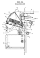
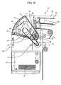
- FIG. 3 is a schematic side view of an embodiment of a customer access module for a media dispenser according to an embodiment of the invention;
- FIG. 4 is a schematic partial cut-away perspective view of an accumulation receptacle according to an embodiment of the invention; and
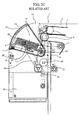
- FIGS. 5A to 5F are schematic views showing sequential operation of a customer access module for the media dispenser according to an embodiment of the invention.
- Hereinafter, the configuration of a preferred embodiment of a customer access module for a media dispenser according to the invention will be described in detail with reference to the accompanying drawings, in which like reference numerals have been utilized to indicate like elements.
- FIG. 3 is a schematic side view of a customer access module for a media dispenser according to an embodiment of the invention, while FIG. 4 is a schematic partially cut-away perspective view of an accumulation box or receptacle according to an embodiment of the invention.
- Referring to FIGS. 3 and 4, a
customer access module 50 is installed at a front end of amedia dispenser 30. Themedia dispenser 30 is provided with a media storage unit (not shown) in which media M are stored, a feed module (not shown) and adelivery module 32 that function to draw out and transfer the media M stored in the media storage unit.Feed rollers 34 andbelts 35, for example, may be used to transfer the media M in the feed module (not shown) and thedelivery module 32. - The
customer access module 50 receives media M requested by a customer through the feed module (not shown) and thedelivery module 32 so that the customer can take the media M from thecustomer access module 50. Thecustomer access module 50 includes aframe 52. Theframe 52 may comprise plate-shaped members placed at both side ends of thecustomer access module 50, defining a predetermined space therebetween. A variety of parts are installed on theframe 52 and in the space formed therebetween. - An
entrance 53 is formed at an upper portion of a front end of theframe 52. Theentrance 53 allows an interior of thecustomer access module 50 to communicate with an exterior of themedia dispenser 30. - The
entrance 53 is configured to be selectively opened and closed by adoor 55. Thedoor 55 is driven by adoor motor 56. Thedoor motor 56 is installed at a side of theframe 52 and causes thedoor 55 to move toward a top of theframe 52 so that theentrance 53 can be in the open state. - An accumulation box or
receptacle 60 is installed within the space defined by theframe 52 adjacent theentrance 53. The accumulation box orreceptacle 60 according to an embodiment of the invention is shown in FIG. 4. Anaccumulation space 62 is defined within and by theaccumulation box 60. Media M transferred through thedelivery module 32 are seated and stacked in theaccumulation space 62. Theaccumulation space 62 of the accumulation box orreceptacle 60 can be exposed to the outside through anopening 64. Theopening 64 is formed to have a width and length at least larger than a width and length of the media M. This is to facilitate smooth entry of the media M into theaccumulation space 62. - Further, in the embodiment of FIG. 3, the accumulation box or
receptacle 60 is in the form of a 7-sided body having a cross section of a pentagon, as shown in FIG. 3. Theopening 64 corresponds to an upwardly opened portion of the 7-sided body when theaccumulation box 60 is in a media-receiving position adjacent feeding path for the media M from thedelivery module 32. - A bottom surface of the
accumulation space 62 of the accumulation box orreceptacle 60 functions as afirst accumulation surface 65. The media M transferred through thedelivery module 32 are directly seated and stacked on thefirst accumulation surface 65. In this embodiment, the width and length of thefirst accumulation surface 65 is configured to be larger than a width and length of the media M. - A
second accumulation surface 67 faces thefirst accumulation surface 65 at a predetermined angle and is adjacent to an edge of theopening 64. Thesecond accumulation surface 67 is a surface on which the media M are seated when theaccumulation box 60 is rotated and thebox opening 64 is directed toward theentrance 53. The width w of thesecond accumulation surface 67 is formed to be smaller than a width of the media M. Thesecond accumulation surface 67 functions to protect theaccumulation box 60 fromunauthorized access 60 when theaccumulation box 60 is in the media receiving position and in the case, for example, that thedoor 55 malfunctions and is inadvertently left open or in the case that thedoor 55 is pried open. - A driving force for rotating the
accumulation box 60 is provided by amotor 70. Themotor 70 is installed on theframe 52 and the driving force from themotor 70 is transmitted to theaccumulation box 60 through abelt mechanism 61. That is, thebelt mechanism 61 comprises a drivingpulley 72 installed on a rotary shaft of themotor 70 and a drivenpulley 73 installed on one side end of theaccumulation box 60 so as to be concentric with a center of the side ends of theaccumulation box 60. A drivingbelt 74 is wound around the driving and drivenpulleys - Meanwhile, a
wheel 76 is installed so as to be concentric with the drivenpulley 73. A slot (not shown) is formed in a periphery of thewheel 76.Sensors accumulation box 60 by sensing the slot formed in thewheel 76. Thesensors frame 52. - The
sensor 80 detects an initial position of theaccumulation box 60, i.e., the initial position in which theopening 64 is directed toward thedelivery module 32 from which the media M are transferred. Thesensor 82 detects the position of theaccumulation box 60 in which a customer can withdraw the media M stacked on thesecond accumulation surface 67 from theaccumulation box 60, i.e., the position of theaccumulation box 60 in which thebox opening 64 is directed toward theentrance 53. Thesensor 84 detects the position of theaccumulation box 60 in which thebox opening 64 is directed toward a collector box orreceptacle 90, as described below. - The collector box or
receptacle 90 is installed below thecustomer access module 50. An opening 91 is formed at a top of thecollector box 90. Thecollector box 90 receives media M that the customer has not taken through the opening 91. - The operation of a customer access module for the media dispenser according to an embodiment of the invention will be hereinafter described in detail.
- FIGS. 5A to 5F show sequential operations of a customer access module according to an embodiment of the invention. The operation of the
customer access module 50 according to an embodiment of the invention will be explained with reference to FIGS. 5A to 5F. - First, in a state as shown in FIG. 5A, the
door 55 covers theentrance 53. Media M are transferred from thedelivery module 32, pass through theopening 64, and are then stacked on thefirst accumulation surface 65. Such an operation is continuously performed until a desired number of sheets of media M are stacked on thefirst accumulation surface 65. In this state, the slot of thewheel 76 is located at a position corresponding to thesensor 80, and thus, thesensor 80 detects that theaccumulation box 60 is in the initial state. - When a number of sheets of media M desired by the customer is stacked on the
first accumulation surface 65, theaccumulation box 60 is rotated by driving themotor 70. At this time, theaccumulation box 60 is rotated through 90 degrees counterclockwise, as viewed in FIG. 5B. In this state, theopening 64 of theaccumulation box 60 is directed toward theentrance 53, and the media M are seated on thesecond accumulation surface 67 due to the rotation of theaccumulation box 60, as shown in FIG. 5B. In this state, lateral sides of the media M are directed toward theentrance 53. Since the media M has a width larger than a width w of thesecond accumulation surface 67, the media M protrudes through theopening 64. In this position, thesensor 82 detects the slot of thewheel 76. - After the
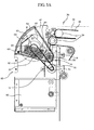
accumulation box 60 has been rotated, thedoor 55 is opened so that theentrance 53 is in an open state. That is, thedoor motor 56 is operated to cause thedoor 55 to move toward a top of theframe 52 so that theentrance 53 is open, as shown in FIG. 5C. In this state, the media M protrudes such that the lateral sides are exposed to the outside through theopening 64 of theaccumulation box 60, and thus, the customer can take the media M from theaccumulation box 60. - Meanwhile, when the customer has taken the media M from the
accumulation box 60, thedoor 55 is closed to cover theentrance 53, and theaccumulation box 60 is rotated back to the initial state. On the other hand, if the customer does not take the media M from theaccumulation box 60 within a predetermined period of time, thedoor 55 is closed as shown in FIG. 5D. - When the
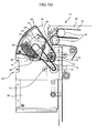
door 55 is closed, themotor 70 again rotates theaccumulation box 60 counterclockwise. That is, themotor 70 is operated to rotate theaccumulation box 60 until thesensor 84 detects the slot of thewheel 76. When theopening 64 of theaccumulation box 60 is directed toward a top of thecollector box 90, the media M that remain seated on thesecond accumulation surface 67 fall down due to their weight and enter thecollector box 90, as shown in FIG. 5E. Since themotor 70 rotates theaccumulation box 60 through at least 180 degrees, theaccumulation box 60 is moved to positions in which the media can be accumulated, in which the customer can take the media M from theaccumulation box 60, and in which the media M are collected in thecollection box 90, respectively. - Thereafter, the
motor 70 is continuously operated to rotate theaccumulation box 60 counterclockwise until theaccumulation box 60 returns to the initial position in which media M transferred from thedelivery module 32 can be accumulated in theaccumulation space 62. That is, thebox motor 70 is operated until thesensor 80 detects the slot of thewheel 76, so that theopening 64 of theaccumulation box 60 is in a state as shown in FIG. 5F. It will be apparent that the initial state can be established by rotating theaccumulation box 60 clockwise from the state shown in FIG. 5E. - The invention solves at least the following problems associated with the related and prior art devices.
- Embodiments of the invention provide a customer access module for a media dispenser wherein an operation of emptying media into a collector box can be more smoothly made with a reduced load.
- Embodiments of the invention also provide a customer access module for a media dispenser capable of completely emptying even a small number of sheets of media into a collector box. That is, the media M can be completely transferred into the collector box since the accumulation box in which media are stacked can be rotated through 360 degrees.
- Further, since the accumulation box is rotated about centers of side ends thereof and the driving force is transmitted through a belt mechanism, there is no load generated on the structure for rotating the accumulation box. In addition, since there is no load generated capable of distorting the accumulation box, a load exerted on the motor is minimized.
- Moreover, there are advantages in that, since the accumulation box is driven by the belt, the problem of breakage resulting from gear engagement in the related art can be solved and it is possible to obtain a damping function due to tension of the belt.
- Finally, there is an advantage in that since lateral sides of the media protrude from the accumulation box and are exposed to the customer by rotation of the accumulation box, the customer can more easily take the media.
- The foregoing embodiments and advantages are merely exemplary and are not to be construed as limiting the invention. The present teaching can be readily applied to other types of apparatuses. The description of the invention is intended to be illustrative, and not to limit the scope of the claims. Many alternatives, modifications, and variations will be apparent to those skilled in the art. In the claims, means-plus-function clauses are intended to cover the structures described herein as performing the recited function and not only structural equivalents but also equivalent structures.
Claims (13)
- A customer access module for a media dispenser, comprising:a frame defining an inner space;an accumulation receptacle rotatably installed within the space in the frame and comprising an opening configured to receive media therethrough and at least one surface on which media are stacked; anda driving source for providing a driving force for driving the accumulation receptacle.
- The module as claimed in claim 1, wherein the accumulation receptacle has a first accumulation surface on which media are initially stacked and a second accumulation surface facing the first accumulation surface at a predetermined angle with respect thereto.
- A customer access module for a media dispenser, comprising:a frame defining an inner space;an accumulation receptacle rotatably installed within the space in the frame and comprising an opening configured to receive media therethrough, a first accumulation surface on which media are initially stacked, and a second accumulation surface facing the first accumulation surface at a predetermined angle with respect thereto, wherein the second surface is configured to prevent unauthorized access to the media disposed on the first accumulation surface; anda driving unit configured to rotate the accumulation receptacle.
- The module as claimed in claim 1, 2, or 3, wherein the driving unit comprises:a driving source configured to provide a driving force for rotating the accumulation receptacle; anda belt mechanism configured to receive the driving force from the box driving source and rotate the accumulation receptacle.
- The module as claimed in claim 4, wherein the belt mechanism comprises:a driven pulley installed on the accumulation receptacle, a driving pulley installed on the driving source, and a belt for transmitting the driving force between the driving and driven pulleys.
- The module as claimed in claim 1, 2, 3, 4 or 5, further comprising a door configured to be selectively opened and closed to provide access by a user to the space.
- The module as claimed in any one of claims 1 to 6, wherein the accumulation receptacle is in the shape of a pentagon in cross-section.
- The module as claimed in any one of claims 1 to 7, wherein a width w of the second accumulation surface is smaller than a width of the media.
- The module as claimed in any one of claims 1 to 8, further comprising a collector receptacle configured to collect media that have not been removed by a user from the module provided below the accumulation receptacle.
- The module as claimed in claim 9, wherein the accumulation receptacle is configured to be rotated by the driving unit between a position in which the first accumulation surface faces in a direction in which the media are fed thereinto and a position in which the first accumulation surface faces the opening of the collector receptacle.
- The module as claimed in any one of claims 1 to 10, wherein the accumulation receptacle, is configured to be rotated 360 degrees.
- The module as claimed in any one of claims 1 to 11, further comprising a wheel configured to be installed concentric with the driven pulley, and a plurality of sensors configured to detect rotational positions of the wheel provided on the frame.
- An automated teller machine comprising the customer access module of any one of claims 1 to 12.
Applications Claiming Priority (2)
| Application Number | Priority Date | Filing Date | Title |
|---|---|---|---|
| KR10-2002-0075676A KR100509032B1 (en) | 2002-11-30 | 2002-11-30 | A customer access module for media dispenser |
| KR2002075676 | 2002-11-30 |
Publications (3)
| Publication Number | Publication Date |
|---|---|
| EP1424660A2 true EP1424660A2 (en) | 2004-06-02 |
| EP1424660A3 EP1424660A3 (en) | 2004-12-15 |
| EP1424660B1 EP1424660B1 (en) | 2013-11-13 |
Family
ID=32291830
Family Applications (1)
| Application Number | Title | Priority Date | Filing Date |
|---|---|---|---|
| EP03026945.0A Expired - Fee Related EP1424660B1 (en) | 2002-11-30 | 2003-11-25 | Costumer access module for a media dispenser |
Country Status (4)
| Country | Link |
|---|---|
| US (1) | US7048180B2 (en) |
| EP (1) | EP1424660B1 (en) |
| KR (1) | KR100509032B1 (en) |
| CN (1) | CN100509595C (en) |
Cited By (1)
| Publication number | Priority date | Publication date | Assignee | Title |
|---|---|---|---|---|
| EP2219158A1 (en) * | 2009-02-17 | 2010-08-18 | Laurel Precision Machines Co., Ltd. | Paper money processor |
Families Citing this family (8)
| Publication number | Priority date | Publication date | Assignee | Title |
|---|---|---|---|---|
| KR100866400B1 (en) * | 2002-12-10 | 2008-11-03 | 엘지엔시스(주) | A method and apparatus of media collecting for media dispenser |
| KR100688246B1 (en) * | 2005-06-13 | 2007-03-02 | 노틸러스효성 주식회사 | Apparatus for drawing bills in a cash transaction machine and method of rejecting bills in the apparatus |
| KR101283084B1 (en) * | 2007-02-05 | 2013-07-05 | 주식회사 엘지씨엔에스 | Device for Discharging a Bundle of Media of a Automated Media Dispenser |
| KR100981776B1 (en) | 2008-12-10 | 2010-09-13 | 엘지엔시스(주) | A customer access module for media dispenser |
| CN102396007A (en) * | 2009-04-16 | 2012-03-28 | 卡纳安·拉卡斯密纳拉扬 | Multi-functional integrated cam -gear- encoder |
| US8899570B2 (en) * | 2012-12-27 | 2014-12-02 | Nautilus Hyosung Inc. | Moving rail assembly and apparatus for receiving and dispensing bill |
| JP6054818B2 (en) * | 2013-06-24 | 2016-12-27 | 日立オムロンターミナルソリューションズ株式会社 | Shutter device and automatic transaction apparatus including the same |
| CN108428280B (en) * | 2017-02-14 | 2020-07-24 | 山东新北洋信息技术股份有限公司 | Paper money temporary storage mechanism and paper money processing device |
Citations (3)
| Publication number | Priority date | Publication date | Assignee | Title |
|---|---|---|---|---|
| US3784090A (en) | 1972-07-28 | 1974-01-08 | Chubb Ind Ltd | Safe deposit apparatus |
| US5172643A (en) | 1990-07-16 | 1992-12-22 | Oki Electric Industry Co., Ltd. | Apparatus for handling strips of paper |
| GB2278154A (en) | 1993-05-21 | 1994-11-23 | Rosspark Ltd | Transfer apparatus for a depository |
Family Cites Families (15)
| Publication number | Priority date | Publication date | Assignee | Title |
|---|---|---|---|---|
| US2581621A (en) * | 1948-11-23 | 1952-01-08 | Diebold Inc | Night depository theftproof closure construction |
| US2776090A (en) * | 1953-04-27 | 1957-01-01 | Sr William T Wright | Night deposit safe having cardreceiving apparatus |
| US3715569A (en) * | 1970-07-29 | 1973-02-06 | Docutel Corp | Credit card automatic currency dispenser |
| US3762634A (en) * | 1971-12-30 | 1973-10-02 | Diebold Inc | Rotary depository construction |
| US4063520A (en) * | 1976-04-30 | 1977-12-20 | The Meilink Steel Safe Company | Night depository closure |
| US4251009A (en) * | 1978-04-03 | 1981-02-17 | Mclaughlin Richard S | Security door assembly for an automatic document dispensing device |
| JPS60164585A (en) * | 1984-02-08 | 1985-08-27 | 株式会社熊平製作所 | Night strong box |
| US4754126A (en) * | 1987-04-01 | 1988-06-28 | Ncr Corporation | Night depository method and apparatus |
| KR100371462B1 (en) * | 1995-09-13 | 2003-09-02 | 주식회사 엘지이아이 | Paper money transfer unit of cash dispenser and transferring method thereof |
| GB9523378D0 (en) * | 1995-11-16 | 1996-01-17 | At & T Global Inf Solution | A cash dispensing apparatus |
| GB9812837D0 (en) * | 1998-06-16 | 1998-08-12 | Ncr Int Inc | Sheet dispensing mechanism |
| US6328208B1 (en) * | 1998-12-29 | 2001-12-11 | Diebold, Incorporated | Network connected night depository |
| JP2000331214A (en) * | 1999-05-21 | 2000-11-30 | Hitachi Ltd | Paper sheet handling device and automatic transaction device |
| KR100527162B1 (en) * | 1999-11-13 | 2005-11-09 | 엘지엔시스(주) | dispenser unit and cash dispenser using the same |
| KR100371361B1 (en) * | 2001-03-26 | 2003-02-07 | 엘지엔시스(주) | Power transmission apparatus and cash dipositing/dispensing device having thereof |
-
2002
- 2002-11-30 KR KR10-2002-0075676A patent/KR100509032B1/en active IP Right Grant
-
2003
- 2003-11-25 EP EP03026945.0A patent/EP1424660B1/en not_active Expired - Fee Related
- 2003-11-25 US US10/720,390 patent/US7048180B2/en active Active
- 2003-11-28 CN CNB2003101199777A patent/CN100509595C/en not_active Expired - Fee Related
Patent Citations (3)
| Publication number | Priority date | Publication date | Assignee | Title |
|---|---|---|---|---|
| US3784090A (en) | 1972-07-28 | 1974-01-08 | Chubb Ind Ltd | Safe deposit apparatus |
| US5172643A (en) | 1990-07-16 | 1992-12-22 | Oki Electric Industry Co., Ltd. | Apparatus for handling strips of paper |
| GB2278154A (en) | 1993-05-21 | 1994-11-23 | Rosspark Ltd | Transfer apparatus for a depository |
Cited By (2)
| Publication number | Priority date | Publication date | Assignee | Title |
|---|---|---|---|---|
| EP2219158A1 (en) * | 2009-02-17 | 2010-08-18 | Laurel Precision Machines Co., Ltd. | Paper money processor |
| US8485338B2 (en) | 2009-02-17 | 2013-07-16 | Laurel Precision Machines Co., Ltd. | Paper money processor |
Also Published As
| Publication number | Publication date |
|---|---|
| KR20040047449A (en) | 2004-06-05 |
| KR100509032B1 (en) | 2005-08-19 |
| CN1513745A (en) | 2004-07-21 |
| US7048180B2 (en) | 2006-05-23 |
| EP1424660B1 (en) | 2013-11-13 |
| CN100509595C (en) | 2009-07-08 |
| US20040108328A1 (en) | 2004-06-10 |
| EP1424660A3 (en) | 2004-12-15 |
Similar Documents
| Publication | Publication Date | Title |
|---|---|---|
| US6942207B2 (en) | Bill receiving/dispensing box | |
| US8430396B2 (en) | Voucher cassette | |
| US7048180B2 (en) | Customer access module for a media dispenser | |
| KR0120913B1 (en) | Bill processor | |
| KR101916576B1 (en) | Bill separating and stacking unit | |
| KR100675238B1 (en) | Money inputting machine | |
| KR20010030307A (en) | Extraction Equipment For Paper Money | |
| US20020152167A1 (en) | Automated teller machine | |
| EP0989082B1 (en) | Apparatus for dispensing notes | |
| JP2003248855A (en) | Paper sheet processing device | |
| JP3323334B2 (en) | Bill dispensing device | |
| KR100981776B1 (en) | A customer access module for media dispenser | |
| JPH0718660Y2 (en) | Banknote conveyor | |
| KR102501645B1 (en) | Shutter apparatus for bill counter with reduced height | |
| KR102583294B1 (en) | Automated teller machine, automated teller machine assembly and automated teller machine system | |
| KR100533279B1 (en) | A customer access module for media dispenser | |
| JP2002145462A (en) | Bank note processing device | |
| KR102640134B1 (en) | Automated teller machine and automated teller machine system | |
| JP2005004375A (en) | Bank bill discriminating device | |
| KR100603522B1 (en) | Delivery type customer access module | |
| CN210836300U (en) | Paper money storage device and cash recycling equipment | |
| JP2543178B2 (en) | Banknote automatic deposit / withdrawal device | |
| JP3556468B2 (en) | Sheet transport device of sheet processing machine | |
| KR950007855Y1 (en) | Cash withdrawal equipment for cash dispenser | |
| KR200269143Y1 (en) | Automatic Coin Teller Machine |
Legal Events
| Date | Code | Title | Description |
|---|---|---|---|
| PUAI | Public reference made under article 153(3) epc to a published international application that has entered the european phase |
Free format text: ORIGINAL CODE: 0009012 |
|
| 17P | Request for examination filed |
Effective date: 20031223 |
|
| AK | Designated contracting states |
Kind code of ref document: A2 Designated state(s): AT BE BG CH CY CZ DE DK EE ES FI FR GB GR HU IE IT LI LU MC NL PT RO SE SI SK TR |
|
| AX | Request for extension of the european patent |
Extension state: AL LT LV MK |
|
| PUAL | Search report despatched |
Free format text: ORIGINAL CODE: 0009013 |
|
| AK | Designated contracting states |
Kind code of ref document: A3 Designated state(s): AT BE BG CH CY CZ DE DK EE ES FI FR GB GR HU IE IT LI LU MC NL PT RO SE SI SK TR |
|
| AX | Request for extension of the european patent |
Extension state: AL LT LV MK |
|
| AKX | Designation fees paid |
Designated state(s): DE FR GB |
|
| GRAP | Despatch of communication of intention to grant a patent |
Free format text: ORIGINAL CODE: EPIDOSNIGR1 |
|
| INTG | Intention to grant announced |
Effective date: 20130523 |
|
| RAP1 | Party data changed (applicant data changed or rights of an application transferred) |
Owner name: LG CNS CO., LTD. |
|
| GRAS | Grant fee paid |
Free format text: ORIGINAL CODE: EPIDOSNIGR3 |
|
| GRAA | (expected) grant |
Free format text: ORIGINAL CODE: 0009210 |
|
| AK | Designated contracting states |
Kind code of ref document: B1 Designated state(s): DE FR GB |
|
| REG | Reference to a national code |
Ref country code: GB Ref legal event code: FG4D |
|
| REG | Reference to a national code |
Ref country code: DE Ref legal event code: R096 Ref document number: 60345284 Country of ref document: DE Effective date: 20140109 |
|
| REG | Reference to a national code |
Ref country code: DE Ref legal event code: R097 Ref document number: 60345284 Country of ref document: DE |
|
| PLBE | No opposition filed within time limit |
Free format text: ORIGINAL CODE: 0009261 |
|
| STAA | Information on the status of an ep patent application or granted ep patent |
Free format text: STATUS: NO OPPOSITION FILED WITHIN TIME LIMIT |
|
| REG | Reference to a national code |
Ref country code: FR Ref legal event code: ST Effective date: 20140917 |
|
| 26N | No opposition filed |
Effective date: 20140814 |
|
| GBPC | Gb: european patent ceased through non-payment of renewal fee |
Effective date: 20140213 |
|
| REG | Reference to a national code |
Ref country code: DE Ref legal event code: R097 Ref document number: 60345284 Country of ref document: DE Effective date: 20140814 |
|
| PG25 | Lapsed in a contracting state [announced via postgrant information from national office to epo] |
Ref country code: FR Free format text: LAPSE BECAUSE OF NON-PAYMENT OF DUE FEES Effective date: 20140113 |
|
| PG25 | Lapsed in a contracting state [announced via postgrant information from national office to epo] |
Ref country code: GB Free format text: LAPSE BECAUSE OF NON-PAYMENT OF DUE FEES Effective date: 20140213 |
|
| REG | Reference to a national code |
Ref country code: DE Ref legal event code: R082 Ref document number: 60345284 Country of ref document: DE Representative=s name: VOSSIUS & PARTNER PATENTANWAELTE RECHTSANWAELT, DE Ref country code: DE Ref legal event code: R081 Ref document number: 60345284 Country of ref document: DE Owner name: ATEC AP CO., LTD., SEONGNAM-SI, KR Free format text: FORMER OWNER: LG CNS CO., LTD., SEOUL, KR |
|
| PGFP | Annual fee paid to national office [announced via postgrant information from national office to epo] |
Ref country code: DE Payment date: 20201106 Year of fee payment: 18 |
|
| REG | Reference to a national code |
Ref country code: DE Ref legal event code: R119 Ref document number: 60345284 Country of ref document: DE |
|
| PG25 | Lapsed in a contracting state [announced via postgrant information from national office to epo] |
Ref country code: DE Free format text: LAPSE BECAUSE OF NON-PAYMENT OF DUE FEES Effective date: 20220601 |