EP1431653A2 - Light source for white color LED lighting and white color led lighting device - Google Patents
Light source for white color LED lighting and white color led lighting device Download PDFInfo
- Publication number
- EP1431653A2 EP1431653A2 EP03017665A EP03017665A EP1431653A2 EP 1431653 A2 EP1431653 A2 EP 1431653A2 EP 03017665 A EP03017665 A EP 03017665A EP 03017665 A EP03017665 A EP 03017665A EP 1431653 A2 EP1431653 A2 EP 1431653A2
- Authority
- EP
- European Patent Office
- Prior art keywords
- white led
- plate
- led lighting
- light source
- lamp
- Prior art date
- Legal status (The legal status is an assumption and is not a legal conclusion. Google has not performed a legal analysis and makes no representation as to the accuracy of the status listed.)
- Withdrawn
Links
Images


Classifications
-
- F—MECHANICAL ENGINEERING; LIGHTING; HEATING; WEAPONS; BLASTING
- F21—LIGHTING
- F21S—NON-PORTABLE LIGHTING DEVICES; SYSTEMS THEREOF; VEHICLE LIGHTING DEVICES SPECIALLY ADAPTED FOR VEHICLE EXTERIORS
- F21S13/00—Non-electric lighting devices or systems employing a point-like light source; Non-electric lighting devices or systems employing a light source of unspecified shape
- F21S13/02—Devices intended to be fixed, e.g. ceiling lamp, wall lamp
- F21S13/10—Devices intended to be fixed, e.g. ceiling lamp, wall lamp with a standard, e.g. street lamp
-
- F—MECHANICAL ENGINEERING; LIGHTING; HEATING; WEAPONS; BLASTING
- F21—LIGHTING
- F21V—FUNCTIONAL FEATURES OR DETAILS OF LIGHTING DEVICES OR SYSTEMS THEREOF; STRUCTURAL COMBINATIONS OF LIGHTING DEVICES WITH OTHER ARTICLES, NOT OTHERWISE PROVIDED FOR
- F21V5/00—Refractors for light sources
- F21V5/02—Refractors for light sources of prismatic shape
-
- F—MECHANICAL ENGINEERING; LIGHTING; HEATING; WEAPONS; BLASTING
- F21—LIGHTING
- F21S—NON-PORTABLE LIGHTING DEVICES; SYSTEMS THEREOF; VEHICLE LIGHTING DEVICES SPECIALLY ADAPTED FOR VEHICLE EXTERIORS
- F21S8/00—Lighting devices intended for fixed installation
- F21S8/08—Lighting devices intended for fixed installation with a standard
- F21S8/085—Lighting devices intended for fixed installation with a standard of high-built type, e.g. street light
- F21S8/086—Lighting devices intended for fixed installation with a standard of high-built type, e.g. street light with lighting device attached sideways of the standard, e.g. for roads and highways
-
- F—MECHANICAL ENGINEERING; LIGHTING; HEATING; WEAPONS; BLASTING
- F21—LIGHTING
- F21S—NON-PORTABLE LIGHTING DEVICES; SYSTEMS THEREOF; VEHICLE LIGHTING DEVICES SPECIALLY ADAPTED FOR VEHICLE EXTERIORS
- F21S9/00—Lighting devices with a built-in power supply; Systems employing lighting devices with a built-in power supply
- F21S9/02—Lighting devices with a built-in power supply; Systems employing lighting devices with a built-in power supply the power supply being a battery or accumulator
- F21S9/03—Lighting devices with a built-in power supply; Systems employing lighting devices with a built-in power supply the power supply being a battery or accumulator rechargeable by exposure to light
- F21S9/035—Lighting devices with a built-in power supply; Systems employing lighting devices with a built-in power supply the power supply being a battery or accumulator rechargeable by exposure to light the solar unit being integrated within the support for the lighting unit, e.g. within or on a pole
-
- F—MECHANICAL ENGINEERING; LIGHTING; HEATING; WEAPONS; BLASTING
- F21—LIGHTING
- F21V—FUNCTIONAL FEATURES OR DETAILS OF LIGHTING DEVICES OR SYSTEMS THEREOF; STRUCTURAL COMBINATIONS OF LIGHTING DEVICES WITH OTHER ARTICLES, NOT OTHERWISE PROVIDED FOR
- F21V19/00—Fastening of light sources or lamp holders
- F21V19/001—Fastening of light sources or lamp holders the light sources being semiconductors devices, e.g. LEDs
- F21V19/0015—Fastening arrangements intended to retain light sources
- F21V19/002—Fastening arrangements intended to retain light sources the fastening means engaging the encapsulation or the packaging of the semiconductor device
-
- F—MECHANICAL ENGINEERING; LIGHTING; HEATING; WEAPONS; BLASTING
- F21—LIGHTING
- F21V—FUNCTIONAL FEATURES OR DETAILS OF LIGHTING DEVICES OR SYSTEMS THEREOF; STRUCTURAL COMBINATIONS OF LIGHTING DEVICES WITH OTHER ARTICLES, NOT OTHERWISE PROVIDED FOR
- F21V19/00—Fastening of light sources or lamp holders
- F21V19/001—Fastening of light sources or lamp holders the light sources being semiconductors devices, e.g. LEDs
- F21V19/0015—Fastening arrangements intended to retain light sources
- F21V19/0025—Fastening arrangements intended to retain light sources the fastening means engaging the conductors of the light source, i.e. providing simultaneous fastening of the light sources and their electric connections
-
- F—MECHANICAL ENGINEERING; LIGHTING; HEATING; WEAPONS; BLASTING
- F21—LIGHTING
- F21V—FUNCTIONAL FEATURES OR DETAILS OF LIGHTING DEVICES OR SYSTEMS THEREOF; STRUCTURAL COMBINATIONS OF LIGHTING DEVICES WITH OTHER ARTICLES, NOT OTHERWISE PROVIDED FOR
- F21V29/00—Protecting lighting devices from thermal damage; Cooling or heating arrangements specially adapted for lighting devices or systems
- F21V29/15—Thermal insulation
-
- F—MECHANICAL ENGINEERING; LIGHTING; HEATING; WEAPONS; BLASTING
- F21—LIGHTING
- F21V—FUNCTIONAL FEATURES OR DETAILS OF LIGHTING DEVICES OR SYSTEMS THEREOF; STRUCTURAL COMBINATIONS OF LIGHTING DEVICES WITH OTHER ARTICLES, NOT OTHERWISE PROVIDED FOR
- F21V29/00—Protecting lighting devices from thermal damage; Cooling or heating arrangements specially adapted for lighting devices or systems
- F21V29/50—Cooling arrangements
- F21V29/70—Cooling arrangements characterised by passive heat-dissipating elements, e.g. heat-sinks
- F21V29/83—Cooling arrangements characterised by passive heat-dissipating elements, e.g. heat-sinks the elements having apertures, ducts or channels, e.g. heat radiation holes
-
- F—MECHANICAL ENGINEERING; LIGHTING; HEATING; WEAPONS; BLASTING
- F21—LIGHTING
- F21W—INDEXING SCHEME ASSOCIATED WITH SUBCLASSES F21K, F21L, F21S and F21V, RELATING TO USES OR APPLICATIONS OF LIGHTING DEVICES OR SYSTEMS
- F21W2131/00—Use or application of lighting devices or systems not provided for in codes F21W2102/00-F21W2121/00
- F21W2131/10—Outdoor lighting
- F21W2131/103—Outdoor lighting of streets or roads
-
- F—MECHANICAL ENGINEERING; LIGHTING; HEATING; WEAPONS; BLASTING
- F21—LIGHTING
- F21Y—INDEXING SCHEME ASSOCIATED WITH SUBCLASSES F21K, F21L, F21S and F21V, RELATING TO THE FORM OR THE KIND OF THE LIGHT SOURCES OR OF THE COLOUR OF THE LIGHT EMITTED
- F21Y2105/00—Planar light sources
- F21Y2105/10—Planar light sources comprising a two-dimensional array of point-like light-generating elements
-
- F—MECHANICAL ENGINEERING; LIGHTING; HEATING; WEAPONS; BLASTING
- F21—LIGHTING
- F21Y—INDEXING SCHEME ASSOCIATED WITH SUBCLASSES F21K, F21L, F21S and F21V, RELATING TO THE FORM OR THE KIND OF THE LIGHT SOURCES OR OF THE COLOUR OF THE LIGHT EMITTED
- F21Y2115/00—Light-generating elements of semiconductor light sources
- F21Y2115/10—Light-emitting diodes [LED]
-
- Y—GENERAL TAGGING OF NEW TECHNOLOGICAL DEVELOPMENTS; GENERAL TAGGING OF CROSS-SECTIONAL TECHNOLOGIES SPANNING OVER SEVERAL SECTIONS OF THE IPC; TECHNICAL SUBJECTS COVERED BY FORMER USPC CROSS-REFERENCE ART COLLECTIONS [XRACs] AND DIGESTS
- Y02—TECHNOLOGIES OR APPLICATIONS FOR MITIGATION OR ADAPTATION AGAINST CLIMATE CHANGE
- Y02B—CLIMATE CHANGE MITIGATION TECHNOLOGIES RELATED TO BUILDINGS, e.g. HOUSING, HOUSE APPLIANCES OR RELATED END-USER APPLICATIONS
- Y02B20/00—Energy efficient lighting technologies, e.g. halogen lamps or gas discharge lamps
- Y02B20/72—Energy efficient lighting technologies, e.g. halogen lamps or gas discharge lamps in street lighting
-
- Y—GENERAL TAGGING OF NEW TECHNOLOGICAL DEVELOPMENTS; GENERAL TAGGING OF CROSS-SECTIONAL TECHNOLOGIES SPANNING OVER SEVERAL SECTIONS OF THE IPC; TECHNICAL SUBJECTS COVERED BY FORMER USPC CROSS-REFERENCE ART COLLECTIONS [XRACs] AND DIGESTS
- Y10—TECHNICAL SUBJECTS COVERED BY FORMER USPC
- Y10S—TECHNICAL SUBJECTS COVERED BY FORMER USPC CROSS-REFERENCE ART COLLECTIONS [XRACs] AND DIGESTS
- Y10S362/00—Illumination
- Y10S362/80—Light emitting diode
Definitions
- the present invention relates to a white LED lighting device suitable for application to illumination lamps, and specifically to street lamps installed in public places such as streets and parks.
- the invention also relates to a light source for white LED lighting, for use as the light source in the aforesaid lighting device.
- LEDs light emitting diodes
- the present inventors have previously proposed a novel lighting device which uses LEDs as its light source and which will provide an LED lighting device that will save energy and also be more suitable for streetlights etc. (see, for example, Reference 2 below).
- the lighting device of Reference 1 has a plurality of LEDs and is provided with a hollow light-guide plate directly below these LEDs. It is also provided with a support for supporting this light-guide plate along its center axis. A diffusion layer having diffuse reflection characteristics and diffuse transmission characteristics is formed on an inner surface of the light guiding part of the light-guide plate, and a diffuse reflection layer is formed an a surface of the support. The LEDs are arranged along the upper end of the light guiding part.
- a plurality of LED elements are fitted in a distributed arrangement by being removably inserted in a bullet-shaped hollow container-like LED holder unit having a 5-layer structure, said LED holder unit being mounted, integrally and coaxially with a removable lamp base, an a general-purpose socket; wherein electrical connection and disconnection from the lamp base can be achieved by insertion and removal of these LED elements; and a transparent, bullet-shaped cover is removably mounted on the outside thereof so as to form an illumination light with an overall bullet-shaped lamp.
- the previously proposed lighting device having this structure achieves its intended object of providing an energy-saving light, a number of problems still remain to be solved.
- One of these is the risk of excessive stimulation to pedestrians' eyes due to the rather high intensity of individual lights, resulting from a structure in which point light source LED elements are distributed around the periphery of the LED holder unit.
- Another problem is that because a conventional LED element is highly directive (i.e., light is output over a narrow angle), it is difficult to obtain a wide overall spread of light. In other words, the irradiation range (i.e., the illuminated area) per lighting device is small, with the result that more lighting units have to be used to illuminate a unit area.
- the present invention has been made in the light of the above-mentioned facts. It is accordingly an object of the present invention to provide a white LED lighting device such that (i) the lighting unit configuration and design promotes the dispersion of emitted light, (ii) ample illuminance can be guaranteed without increasing the number of LED elements, and (iii) an energy-saving and maintenance-free lighting device can be obtained. It is a further object of the invention to provide a light source for white LED lighting which is optimal for use in said white LED lighting device.
- the present invention as claimed in Claim 1 provides for a method of assembling a light source for white LED lighting, said method comprising the steps of: (i) inserting and holding a plurality of white LED elements 11 in holding holes in reflective plate 9, said plate being constituted by providing a required number of these holding holes, in a matrix-like array of prescribed pitch, in a plate of a shape corresponding to the illuminating surface of lamp body 1; (ii) fixing these white LED elements 11 at locations 2 to 4 mm behind their respective electrode portions 12; (iii) attaching the positive and negative terminals of white LED elements 11 to base plate 10 for the LED elements, said base plate being disposed parallel to and directly behind reflective plate 9; and (iv) forming, at the positive and negative terminals, a series-parallel electrical network suitable for the applied voltage.
- this invention by providing common reflective plate 9 at a location 2 to 4 mm behind the electrode portions of white LED elements 11 arranged in a matrix-like array of prescribed pitch, and due to the apparent increase in the number of white LED elements 11 and the effective optical reflection an efficient and loss-free frontal irradiation is provided.
- This makes it possible to maintain ample illuminance while minimizing the number of white LED elements 11. Accordingly, this light source for white LED lighting is advantageous in application to white LED lighting devices such as streetlights.
- the present invention as claimed in Claim 2 is a white LED lighting device consisting of: (A) lamp body 1 provided with lamp casing 7, colourless transparent globe 8 matchingly fixed to an opening in the bottom of this lamp casing 7, light source 3 for white LED lighting housed in lamp casing 7, and light source controller 6 likewise housed in lamp casing 7; (B) lamp support 2 for supporting lamp body 1 in an attitude or position such that the illuminating surface of the lamp body is directed downward and its axis in the longer or longitudinal direction extends forwards with a slight upward tilt; and (C) power source device 4 housed in the lower part of lamp support 2 and serving to supply electric power to light source 3 for white LED lighting; this white LED lighting device being characterized in that: (D) lamp casing 7 and globe 8 have, in those parts facing light source 3 for white LED lighting, a transverse sectional shape which is rectangular in rear portions 7A and 8A that lie towards mounting base 13, the sides of said rectangular shape which are parallel to the above-mentioned longer
- the present invention provides a design which is suitable for outdoor lighting devices such as streetlights.
- This suitability derives from the fact that the illuminating surface of globe 8 has overall a "thick quasi-T" shape consisting of a wide rectangle at rear portion 8A and a narrower tapered trapezoid at front portion 8B, thereby giving light distribution characteristics wherein maximum brightness is obtained immediately beneath the lighting device and brightness decreases gradually towards the periphery.
- the invention also creates a synergism between the optical reflection capability, provided by reflective plate 9 and restricted to the forwards direction, and the optical refraction and diffusion capability provided by the corrugations and curved plate of globe B.
- the effective irradiation range of the present invention as projected onto the ground - measuring this range outwards from a point directly below the lighting device - is an approximately elliptical shape whereof the width is greater than the length from front to back.
- the present invention can provide an illuminance distribution with an enlarged irradiation range and which is therefore ideal for streetlights.
- the present invention can provide a lighting device which compares favorably with a conventional fluorescent light in terms of energy consumption. This is because it is clearly different from a cluster of spotlights or the like, in that the entire illuminating surface of globe 8 shines with a uniform brightness which is gentle on the eyes.
- the present invention as claimed in Claim 3 is the white LED lighting device of Claim 2, wherein solar cell 5 is mounted and fixed at the upper end of lamp support 2; power source device 4 is provided with a storage battery; and light source controller 6 is provided with automatic voltage sensing means for sensing the output voltage of solar cell 5, and with automatic electrical storage means which uses the automatic voltage sensing means to cause electric power obtained from solar cell 5 to accumulate in the storage battery.
- the present invention eliminates the need to lay power cables. This is because all the electric power required to power the lighting device during the night can be supplied by means of solar energy alone. The invention therefore also makes a significant contribution to reducing the consumption of electric power.
- the present invention as claimed in Claim 4 is the white LED lighting device of Claim 3, wherein lamp support 2 is formed from a hollow pipe and provided with an air vent in the pipe wall close to the upper end, thereby enabling the hollow portion to produce a chimney effect so that heat generated by ambient air temperature can escape.
- the present invention prevents temperature rise in the storage battery housing space, such a temperature rise having a potentially adverse effect an the battery, thereby extending battery life and improving the reliability of the white LED lighting device.
- the present invention as claimed in Claim 5 is the white LED lighting device of Claim 3 or Claim 4, wherein lamp body 1 is provided with metal heat shield plate 16 mounted in the form of a sunshade directly above lamp casing 7 but leaving a slight air gap between the heat shield plate and the lamp casing.
- the present invention as claimed in Claim 6 is the white LED lighting device of Claim 5, wherein lamp body 1 is provided with air inlets 19 and air outlets 20 in the rear and side faces of the side plate of rear portion 7A of lamp casing 7.
- the white LED lighting device according to the invention as claimed in Claim 5 and Claim 6 suppresses temperature rise inside lamp body 1 during direct exposure to sunlight and during high summer temperatures, thereby stabilizing the performance of light source controller 6 and white LED elements 11, which are sensitive to temperature conditions, and improving device reliability.
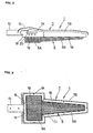
- FIG. 1 is an overall view of a white LED lighting device according to this embodiment, with FIG. 1(B) being a front view and FIG. 1(A) a view from the right side.
- the white LED lighting device illustrated in FIG. 1 comprises a lamp body 1, a lamp support 2, a power source device 4 and a solar cell 5.
- Lamp support 2 is for example an upright single-column stainless steel support composed of a lower bearing portion 15 and a pole portion 21, and has a protruding support arm 14 situated either on an intermediate portion of the support but nearer arranged to the top, as illustrated in FIG. 1, or at the top of the support.
- Lamp support 2 may be used, for example, as a street light support, in which case it is erected on the pedestrian sidewalk near the roadway shoulder, with support arm 14 projecting out over the sidewalk.
- Power source device 4 is provided with the purpose of supplying electric power to light source 3 for white LED lighting (hereinafter termed simply "light source 3").
- Light source 3 is located in lamp body 1 and will be subsequently described.
- a storage battery such as a long-life control valve type lead storage battery is used and this is housed in a prescribed vacant space inside lower bearing portion 15 which constitutes the bottom of support 2. It may be noted that it is also feasible to provide power source device 4 with an inverter (a DC-to-AC converter) in addition to the above-mentioned storage battery, so that in the event of emergency operation being necessary, electric power can be received from a low-voltage distribution line.
- Solar cell 5 is installed an the top of lamp support 2, being fixed in a direction and at an angle of inclination such that it readily receives the maximum amount of sunlight.
- Solar cell 5 is selected from the three types available (polycrystalline, singlecrystal, single-crystal/amorphous), a suitable type being selected in accordance with installation conditions.
- a circuit is constructed in such manner that the power obtained from solar cell 5 is accumulated in storage battery 4 via light source controller 6, which is not illustrated in FIG. 1 but will be described hereinafter. It may be noted that solar cell 5 is not essential and that a lighting device wherein only lamp body 1 is mounted on lamp support 2 and which is adapted to receive power from a power distribution line, is also within the scope of this invention.
- Lamp body 1 has an outer casing with a "thick quasi-T" shape which is longer in the front-to-back depth direction than in the left-to-right width direction, this outer casing being composed of lamp casing 7 and colorless transparent globe 8 matchingly fixed to an opening in the bottom of lamp casing 7.
- Lamp casing 7 is made of stainless steel and globe 8 is made of acrylic resin.
- Lamp body 1 is supported on lamp support 2 by fitting and fixing mounting base 13, which projects integrally at the rear of lamp casing 7, to support arm 14.
- Lamp body 1 is for example fixed in a position approximately 3.5 m directly above the sidewalk and in a position such that its illuminating surface is directed downward and its axis in the longitudinal direction extends forwards with a slight upward tilt.
- FIG. 2, FIG. 3 and FIG. 4 show respectively a side view, a bottom view and a rear view of lamp body 1 of FIG. 1.
- FIG. 5 is an exploded perspective view of lamp body 1 seen in an angle from below.
- FIG. 6 is likewise a perspective view of lamp body 1 but seen from the side.
- FIG. 7 is a schematic vertical sectional view looking through the width of the rear portion of lamp body 1.
- FIG. 8 is an enlarged partial view of light source 3 shown in FIG. 7.
- Lamp body 1 has lamp casing 7, globe 8, light source 3 and light source controller 6.
- Lamp casing 7 and globe 8, which constitute the outer casing of lamp body 1 have, in those parts facing light source 3 which is housed inside the casing, a transverse sectional shape which is rectangular in rear portions 7A and 8A that lie towards mounting base 13, the sides of said rectangular shape which are parallel to the longer direction from front to back being the short sides, and which is a slender (narrower than rear portions 7A and 7B) tapering trapezoid in front portions 7B and 8B that lie integrally adjacent to the rear portions.
- lamp casing 7 When assembling lamp body 1, lamp casing 7 is placed on top relative to globe 8 and the opening portions of these two parts are joined together. Globe edge frame 22 made of stainless steel and fitted to the rim of globe 8 is then fitted inside the rim of lamp casing 7 to form an outer casing with a watertight integral structure obtained by the use of some fixing means such as clamping screws.
- the inside of the illuminating surface of globe 8 is a smooth surface 17; the outside is longitudinally banded concavo-convex surface 18 consisting of adjoining ridges and valleys alternating in succession with a pitch of a few millimetres, for example 5 mm; and the illuminating surface of the globe as a whole is formed as a curved plate with symmetry in the right-left width direction and whereof the bottom is the center line in the longitudinal direction.
- Light source 3 comprises as its constituent elements reflective plate 9, base plate 10 for LED elements (hereinafter termed simply “base plate 10") and the required number of white LED elements 11, and is formed as a plate-type light source with a shape corresponding to the transverse sectional shape of the interior of the above-mentioned outer casing.
- reflective plate 9 is a plate of a metal such as aluminium. A plate of prescribed shape is used, and the front reflective surface of the plate 9 has a specular finish.
- Reflective plate 9 moreover formed by a perforated plate in which holding holes have been made in a matrix-like array of prescribed pitch, the number of holding holes so formed being equal to the prescribed number of white LED elements 11 to be used.
- Examples of this embodiment would be a perforated mirror plate in which the holding holes have been made in a matrix-like array with a staggered configuration, a checkerboard configuration, etc., and where the criterion for hole pitch is to add a gap of 7 mm to the outer diameter of a white LED element 11.
- Each of a prescribed number of bullet-shaped white LED elements 11 is inserted and held in a respective holding hole and thus fixed in reflective plate 9.
- dimensions are determined and fixed so that the front face of reflective plate 9 is positioned 2 to 4 mm (d0 in FIG. 8) behind electrode portion 12.
- the reason for this positioning is simply that the described position of reflective plate 9 gives the optimum conditions for minimizing attenuation of the light emitted by electrode portion 12 and for ensuring that the emitted light is efficiently reflected in a forward direction.
- Base plate 10 is a conventional circuit board. A prescribed number of very small holes are made in base plate 10 in a prescribed arrangement which corresponds to positive terminals 23 and negative terminals 24 of white LED elements 11. These terminals consist of fine conductive wires. Base plate 10 is disposed parallel to and directly behind reflective plate 9, and the above-mentioned very small holes are used to attach positive terminals 23 and negative terminals 24 of white LED elements 11 to base plate 10 by means of solder 25. A series-parallel electrical network suitable for the applied voltage is formed at the positive and negative terminals.
- reflective plate 9 and base plate 10 of this portion are formed into a bent plate having a wide half-angled gutter shape corresponding to the rectangular curved plate of rear portion 8A of globe B.
- reflective plate 9 and base plate 10 are formed as flat plates with elongated trapezoidal shapes corresponding to the elongated trapezoidal curved plate of front portion 8B of globe B.
- the entirety of light source 3 thus configured is housed in lamp casing 7 and positioned therein so that a gap d1 of approximately 20 mm (see FIG. 7) is maintained between light source 3 and globe 8.
- d1 indicates a minimal clearance between light source 3 and globe 8.
- Light source controller 6 is a control system for controlling several functions including turning light source 3 on and off, charging and discharging the storage battery of power source device 4, and connecting and disconnecting solar cell 5.
- Light source controller 6 is provided with control command elements such as a timer and a daylight sensor, automatic voltage sensing means for sensing the output voltage of solar cell 5, and automatic electrical storage means which uses the automatic voltage sensing means to cause electric power obtained from solar cell 5 to accumulate in the storage battery.
- Light source controller 6 is also provided with light source control means for turning light source 3 on and off and for adjusting the amount of emitted light, an the basis of control commands generated by the above-mentioned control command elements. As shown schematically in FIG. 7, light source controller 6, in which these various functional components are integrated, is housed in the vacant space behind light source 3 inside lamp casing 7, with electrical connections to light source 3, power source device 4 and solar cell 5.
- the part referenced 16 in FIG. 2 and FIG. 5 is a heat shield plate and may be added to lamp body 1 if required.
- This optional heat shield plate 16 is a pressed metal plate made of aluminium or the like and has a shape similar to the planar external shape of lamp body 1. It is mounted in the form of a sunshade directly above lamp casing 7 but leaving a slight air gap between the heat shield plate and the lamp casing. The provision of heat shield plate 16 in this way suppresses temperature rise inside lamp body 1 caused by direct exposure of lamp body 1 to sunlight.
- Lamp support 2 is preferably formed from a hollow pipe.
- an air vent (not illustrated) is opened by conventional means in the pipe wall close to the upper end of the support, thereby enabling the hollow portion within the support to produce a chimney effect, with the result that heat generated by the ambient air temperature can be discharged from the air vent. This prevents a temperature rise, stabilizes the performance of the storage battery and extends battery life.
- Air inlet 19 opens in the rear face of the side plate in rear portion 7A of lamp casing 7, while air outlet 20 opens in the side face of the side plate in rear portion 7A.
- Lamp body 1 supported by lamp support 2 is for example fixed in a position approximately 3 to 4 m directly above the sidewalk and in a position such that its illuminating surface is directed downward and its axis in the longitudinal direction extends forwards with a slight upward tilt.
- lamp body 1 is fixed so that it extends forwards with an upward angle of inclination ⁇ 1 equal to 10 degrees from horizontal. It may be noted that in the lighting device shown in FIG.
- light source 3 in the front portion 7B of lamp casing 7 is provided in such a manner that it inclines upward at an angle ⁇ 2 equal to 5 degrees relative to the above-mentioned longitudinal direction axis (x), and consequently light source 3 in the front portion 7B extends forwards with an upward angle of inclination ⁇ 3 equal to 15 degrees from horizontal.
- Lamp body 1 installed as described above lights up in the interval from sunset to sunrise under automatic control by light source controller 6.
- all the required electric power can be supplied by solar energy, by storing the electric power obtained from solar cell 5 in the storage battery of power source device 4 via light source controller 6.
- the present lighting device having high luminance white LED elements 11 as its light source, provides the same level of brightness as a conventional fluorescent light with only approximately one third of the energy consumption.
- Other advantages are that long-term (approximately 13 years) operation with no bulb burn-outs is achievable; attraction to insects is very slight because the wavelength of the emitted light is close to that of sunlight; and illuminance can be maintained even in cold regions where fluorescent lights will not work.
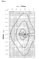
- FIG. 9 shows the illuminance distribution as measured an the ground during operation of a white LED lighting device according to this embodiment of the invention.
- lamp body 1 was positioned at a height of 3450 mm directly above the sidewalk, with its illuminating surface directed downward and its axis (x) in the longer or longitudinal direction extending forwards with an upward angle of inclination ⁇ 1 equal to 10 degrees from the horizontal.
- Lamp body 1 employed 120 white LED elements (NSPW5008S, luminous intensity 9.20 cd per LED) arranged in a staggered configuration, giving a power consumption of about 10 W.
- an illuminance of 42.6 lux was obtained directly beneath lamp body 1, and this decreased (to 35.0 lux, 20.0 lux and 5.0 lux) with increasing distance.
- an illuminance of 1.5 lux was obtained at distances of up to 2.3 m an the roadway side and at distances of up to 3.3 m an the opposite side.
- an illuminance of 1.5 lux was obtained at distances of up to 5.3 m in both forward and backward directions.
- the apparent increase in the number of white LED elements 11 and the effective optical reflection - these characteristics being obtained by the use of a reflective plate in the light source for white LED lighting - in conjunction provide an efficient and loss-free frontal irradiation. This makes it possible to maintain ample illuminance while minimizing the number of white LED elements 11. Accordingly, the light source for white LED lighting of the Invention is advantageous in application to white LED lighting devices such as streetlights.
- the effective irradiation range as projected onto the ground - measuring this range outwards from a point directly below the lighting device - is an approximately elliptical shape whereof the width is greater than the length from front to back. It is therefore possible to obtain an enlarged irradiation range and an illuminance distribution which is ideal for streetlights.
- the white LED lighting device of the Invention is that it is clearly different from a cluster of spotlights or the like, in that the entire illuminating surface of the globe shines with a uniform brightness which is gentle an the eyes. Furthermore, the present Invention can provide a lighting device which compares favorably with a conventional fluorescent light in terms of energy consumption.
- the present invention uses white LED elements for the light source, ample illuminance can be guaranteed over long periods of time at low power loads; overall, low running costs can be maintained; and an energy-saving, maintenance-free lighting device can be realized.
- Yet another advantage of the invention is that by providing both power source device 4, which has a storage battery, and solar cell 5, all the electric power required to light the lighting device during the night can be supplied by means of solar energy alone, and hence the invention contributes to reducing the consumption of electric power and also eliminates the laying of power cables. Furthermore, selection of installation sites is less restricted and installation work is simplified. The present invention will therefore certainly play a significant role in improving streets and their surrounding environments.
Abstract
Description
- The present invention relates to a white LED lighting device suitable for application to illumination lamps, and specifically to street lamps installed in public places such as streets and parks. The invention also relates to a light source for white LED lighting, for use as the light source in the aforesaid lighting device.
- Illumination in streets and parks has conventionally been provided exclusively by incandescent lamps, mercury lamps and fluorescent lamps. However, because these light sources have a relatively high power consumption, the utilization of light emitting diodes (LEDs), which consume much less electric power than fluorescent lamps, has been studied as a means of saving energy. Nevertheless, due to some of their characteristics, such as strong directivity (being a point light source) and the glaring quality of their light, LEDs are not regarded as suitable for outdoors and other types of lighting and hence have not become widely popular in such applications. There are, however, some examples of prior art relating to LED lighting devices in application to indoor and outdoor use (see, for example,
Reference 1 below). - In response to this situation, the present inventors have previously proposed a novel lighting device which uses LEDs as its light source and which will provide an LED lighting device that will save energy and also be more suitable for streetlights etc. (see, for example,
Reference 2 below). - Japanese Unexamined Patent Application Publication No. 11-213730 (p.2-3, paragraphs 9-14, FIGS.1, 2 and 3)
- Japanese Patent Application No. 2002-007762 (p.5-7, paragraphs 8-12, FIGS. 1 and 2)
- The lighting device of
Reference 1 has a plurality of LEDs and is provided with a hollow light-guide plate directly below these LEDs. It is also provided with a support for supporting this light-guide plate along its center axis. A diffusion layer having diffuse reflection characteristics and diffuse transmission characteristics is formed on an inner surface of the light guiding part of the light-guide plate, and a diffuse reflection layer is formed an a surface of the support. The LEDs are arranged along the upper end of the light guiding part. - However, numerous problems are encountered in connection with illuminance and product cost in the case of this
Reference 1 lighting device. Namely, in order to obtain a planar light source from a point light source LEDs, such a lighting device requires a special structure, namely: "provision of (i) a light-guide plate for a plurality of LEDs, this light-guide plate having a light guiding portion obtained by forming, an its inner surface, a diffusion layer having diffuse reflection characteristics and diffuse transmission characteristics, and (ii) a diffuse reflection layer parallel to this light-guide plate". This requirement not only leads to a higher complexity of structure but also results in optical attenuation in the transparent light-guide plate, leading to poor efficiency since a large number of LEDs is needed to obtain a sufficient illuminance. Moreover, a globe to cover these parts is essential for outdoor applications. - On the other hand, in the
Reference 2 lighting device (hereinafter termed the "previously proposed lighting device"), a plurality of LED elements are fitted in a distributed arrangement by being removably inserted in a bullet-shaped hollow container-like LED holder unit having a 5-layer structure, said LED holder unit being mounted, integrally and coaxially with a removable lamp base, an a general-purpose socket; wherein electrical connection and disconnection from the lamp base can be achieved by insertion and removal of these LED elements; and a transparent, bullet-shaped cover is removably mounted on the outside thereof so as to form an illumination light with an overall bullet-shaped lamp. - Although the previously proposed lighting device having this structure achieves its intended object of providing an energy-saving light, a number of problems still remain to be solved. One of these is the risk of excessive stimulation to pedestrians' eyes due to the rather high intensity of individual lights, resulting from a structure in which point light source LED elements are distributed around the periphery of the LED holder unit. Another problem is that because a conventional LED element is highly directive (i.e., light is output over a narrow angle), it is difficult to obtain a wide overall spread of light. In other words, the irradiation range (i.e., the illuminated area) per lighting device is small, with the result that more lighting units have to be used to illuminate a unit area.
- The present invention has been made in the light of the above-mentioned facts. It is accordingly an object of the present invention to provide a white LED lighting device such that (i) the lighting unit configuration and design promotes the dispersion of emitted light, (ii) ample illuminance can be guaranteed without increasing the number of LED elements, and (iii) an energy-saving and maintenance-free lighting device can be obtained. It is a further object of the invention to provide a light source for white LED lighting which is optimal for use in said white LED lighting device.
- To achieve the above-mentioned objects, the present invention as claimed in
Claim 1 provides for a method of assembling a light source for white LED lighting, said method comprising the steps of: (i) inserting and holding a plurality ofwhite LED elements 11 in holding holes inreflective plate 9, said plate being constituted by providing a required number of these holding holes, in a matrix-like array of prescribed pitch, in a plate of a shape corresponding to the illuminating surface oflamp body 1; (ii) fixing thesewhite LED elements 11 atlocations 2 to 4 mm behind theirrespective electrode portions 12; (iii) attaching the positive and negative terminals ofwhite LED elements 11 tobase plate 10 for the LED elements, said base plate being disposed parallel to and directly behindreflective plate 9; and (iv) forming, at the positive and negative terminals, a series-parallel electrical network suitable for the applied voltage. - According to this invention, by providing common
reflective plate 9 at alocation 2 to 4 mm behind the electrode portions ofwhite LED elements 11 arranged in a matrix-like array of prescribed pitch, and due to the apparent increase in the number ofwhite LED elements 11 and the effective optical reflection an efficient and loss-free frontal irradiation is provided. This makes it possible to maintain ample illuminance while minimizing the number ofwhite LED elements 11. Accordingly, this light source for white LED lighting is advantageous in application to white LED lighting devices such as streetlights. - To achieve the above-mentioned objects, the present invention as claimed in
Claim 2 is a white LED lighting device consisting of: (A)lamp body 1 provided withlamp casing 7, colourlesstransparent globe 8 matchingly fixed to an opening in the bottom of thislamp casing 7,light source 3 for white LED lighting housed inlamp casing 7, andlight source controller 6 likewise housed inlamp casing 7; (B)lamp support 2 for supportinglamp body 1 in an attitude or position such that the illuminating surface of the lamp body is directed downward and its axis in the longer or longitudinal direction extends forwards with a slight upward tilt; and (C)power source device 4 housed in the lower part oflamp support 2 and serving to supply electric power tolight source 3 for white LED lighting; this white LED lighting device being characterized in that: (D)lamp casing 7 andglobe 8 have, in those parts facinglight source 3 for white LED lighting, a transverse sectional shape which is rectangular inrear portions mounting base 13, the sides of said rectangular shape which are parallel to the above-mentioned longer direction being the short sides, and which is an elongated trapezoid infront portions globe 8 issmooth surface 17, the outside is longitudinally banded concavo-convex surface 18 consisting of adjoining ridges and valleys alternating in succession with a pitch of a few millimetres, and the illuminating surface ofglobe 8 as a whole is formed as a curved plate with bilateral symmetry whereof the bottom is the center line in the above-mentioned longer direction; (F)light source 3 for white LED lighting is constituted by: (i) inserting and holding a plurality ofwhite LED elements 11 in holding holes inreflective plate 9, this plate providing a required number of these holding holes in the form of a multi-row, multi-column array of prescribed pitch; (ii) fixingwhite LED elements 11 atlocations 2 to 4 mm behind theirrespective electrode portions 12; (iii) attaching the positive and negative terminals ofwhite LED elements 11 tobase plate 10 for the LED elements, this base plate being disposed parallel to and directly behindreflective plate 9; and (iv) forming, at the positive and negative terminals, a series-parallel electrical network suitable for the applied voltage; (G)reflective plate 9 andbase plate 10 for the LED elements inrear portions reflective plate 9 andbase plate 10 for the LED elements infront portions lamp body 1 is enlarged an the basis of a synergism between the optical reflection capability ofreflective plate 9 and the optical refraction capability of the corrugations and curved plate of globe B. - The present invention, as described above, provides a design which is suitable for outdoor lighting devices such as streetlights. This suitability derives from the fact that the illuminating surface of
globe 8 has overall a "thick quasi-T" shape consisting of a wide rectangle atrear portion 8A and a narrower tapered trapezoid atfront portion 8B, thereby giving light distribution characteristics wherein maximum brightness is obtained immediately beneath the lighting device and brightness decreases gradually towards the periphery. The invention also creates a synergism between the optical reflection capability, provided byreflective plate 9 and restricted to the forwards direction, and the optical refraction and diffusion capability provided by the corrugations and curved plate of globe B. On the basis of the above-mentioned design and synergism, the effective irradiation range of the present invention as projected onto the ground - measuring this range outwards from a point directly below the lighting device - is an approximately elliptical shape whereof the width is greater than the length from front to back. This is evident from a diagram of actual measurements showing illuminance distribution, to be described hereinafter. Accordingly, the present invention can provide an illuminance distribution with an enlarged irradiation range and which is therefore ideal for streetlights. Moreover, the present invention can provide a lighting device which compares favorably with a conventional fluorescent light in terms of energy consumption. This is because it is clearly different from a cluster of spotlights or the like, in that the entire illuminating surface ofglobe 8 shines with a uniform brightness which is gentle on the eyes. - To achieve the above-mentioned objects, the present invention as claimed in
Claim 3 is the white LED lighting device ofClaim 2, whereinsolar cell 5 is mounted and fixed at the upper end oflamp support 2;power source device 4 is provided with a storage battery; andlight source controller 6 is provided with automatic voltage sensing means for sensing the output voltage ofsolar cell 5, and with automatic electrical storage means which uses the automatic voltage sensing means to cause electric power obtained fromsolar cell 5 to accumulate in the storage battery. - The present invention, as described in the previous paragraph, eliminates the need to lay power cables. This is because all the electric power required to power the lighting device during the night can be supplied by means of solar energy alone. The invention therefore also makes a significant contribution to reducing the consumption of electric power.
- To achieve the above-mentioned objects, the present invention as claimed in
Claim 4 is the white LED lighting device ofClaim 3, whereinlamp support 2 is formed from a hollow pipe and provided with an air vent in the pipe wall close to the upper end, thereby enabling the hollow portion to produce a chimney effect so that heat generated by ambient air temperature can escape. - The present invention, as described in the previous paragraph, prevents temperature rise in the storage battery housing space, such a temperature rise having a potentially adverse effect an the battery, thereby extending battery life and improving the reliability of the white LED lighting device.
- To achieve the above-mentioned objects, the present invention as claimed in
Claim 5 is the white LED lighting device ofClaim 3 orClaim 4, whereinlamp body 1 is provided with metalheat shield plate 16 mounted in the form of a sunshade directly abovelamp casing 7 but leaving a slight air gap between the heat shield plate and the lamp casing. Further, the present invention as claimed inClaim 6 is the white LED lighting device ofClaim 5, whereinlamp body 1 is provided withair inlets 19 andair outlets 20 in the rear and side faces of the side plate ofrear portion 7A oflamp casing 7. - The white LED lighting device according to the invention as claimed in
Claim 5 andClaim 6 suppresses temperature rise insidelamp body 1 during direct exposure to sunlight and during high summer temperatures, thereby stabilizing the performance oflight source controller 6 andwhite LED elements 11, which are sensitive to temperature conditions, and improving device reliability. -
- FIG. 1 is an overall view of a white LED lighting device according to an embodiment of this invention, with FIG. 1(B) being a front view and FIG. 1(A) a right side view.
- FIG. 2 is a side view of
lamp body 1 of FIG. 1. - FIG. 3 is a bottom view of
lamp body 1 of FIG. 1. - FIG. 4 is a rear view of
lamp body 1 of FIG. 1. - FIG. 5 is an exploded perspective view of
lamp body 1 of FIG. 1, seen in an angle from below. - FIG. 6 is a perspective view of
lamp body 1 of FIG. 1, seen from the side. - FIG. 7 is a schematic vertical sectional view looking through the width of the rear portion of
lamp body 1 of FIG. 1. - FIG. 8 is an enlarged partial view of
light source 3 for white LED lighting, shown in FIG. 7. - FIG. 9 shows the illuminance distribution as measured during operation of a white LED lighting device according to an embodiment of the invention.
-
- An embodiment of the invention will now be described with reference to the accompanying drawings. FIG. 1 is an overall view of a white LED lighting device according to this embodiment, with FIG. 1(B) being a front view and FIG. 1(A) a view from the right side. The white LED lighting device illustrated in FIG. 1 comprises a
lamp body 1, alamp support 2, apower source device 4 and asolar cell 5.Lamp support 2 is for example an upright single-column stainless steel support composed of alower bearing portion 15 and apole portion 21, and has a protrudingsupport arm 14 situated either on an intermediate portion of the support but nearer arranged to the top, as illustrated in FIG. 1, or at the top of the support.Lamp support 2 may be used, for example, as a street light support, in which case it is erected on the pedestrian sidewalk near the roadway shoulder, withsupport arm 14 projecting out over the sidewalk. -
Power source device 4 is provided with the purpose of supplying electric power to lightsource 3 for white LED lighting (hereinafter termed simply "light source 3").Light source 3 is located inlamp body 1 and will be subsequently described. A storage battery such as a long-life control valve type lead storage battery is used and this is housed in a prescribed vacant space insidelower bearing portion 15 which constitutes the bottom ofsupport 2. It may be noted that it is also feasible to providepower source device 4 with an inverter (a DC-to-AC converter) in addition to the above-mentioned storage battery, so that in the event of emergency operation being necessary, electric power can be received from a low-voltage distribution line. -
Solar cell 5 is installed an the top oflamp support 2, being fixed in a direction and at an angle of inclination such that it readily receives the maximum amount of sunlight.Solar cell 5 is selected from the three types available (polycrystalline, singlecrystal, single-crystal/amorphous), a suitable type being selected in accordance with installation conditions. A circuit is constructed in such manner that the power obtained fromsolar cell 5 is accumulated instorage battery 4 vialight source controller 6, which is not illustrated in FIG. 1 but will be described hereinafter. It may be noted thatsolar cell 5 is not essential and that a lighting device whereinonly lamp body 1 is mounted onlamp support 2 and which is adapted to receive power from a power distribution line, is also within the scope of this invention. -
Lamp body 1 has an outer casing with a "thick quasi-T" shape which is longer in the front-to-back depth direction than in the left-to-right width direction, this outer casing being composed oflamp casing 7 and colorlesstransparent globe 8 matchingly fixed to an opening in the bottom oflamp casing 7.Lamp casing 7 is made of stainless steel andglobe 8 is made of acrylic resin.Lamp body 1 is supported onlamp support 2 by fitting and fixing mountingbase 13, which projects integrally at the rear oflamp casing 7, to supportarm 14.Lamp body 1 is for example fixed in a position approximately 3.5 m directly above the sidewalk and in a position such that its illuminating surface is directed downward and its axis in the longitudinal direction extends forwards with a slight upward tilt. - FIG. 2, FIG. 3 and FIG. 4 show respectively a side view, a bottom view and a rear view of
lamp body 1 of FIG. 1. FIG. 5 is an exploded perspective view oflamp body 1 seen in an angle from below. FIG. 6 is likewise a perspective view oflamp body 1 but seen from the side. FIG. 7 is a schematic vertical sectional view looking through the width of the rear portion oflamp body 1. FIG. 8 is an enlarged partial view oflight source 3 shown in FIG. 7. - The structure of
lamp body 1 of a white LED lighting device according to an embodiment of this invention will now be described.Lamp body 1 haslamp casing 7,globe 8,light source 3 andlight source controller 6.Lamp casing 7 andglobe 8, which constitute the outer casing oflamp body 1, have, in those parts facinglight source 3 which is housed inside the casing, a transverse sectional shape which is rectangular inrear portions base 13, the sides of said rectangular shape which are parallel to the longer direction from front to back being the short sides, and which is a slender (narrower thanrear portions front portions lamp body 1,lamp casing 7 is placed on top relative toglobe 8 and the opening portions of these two parts are joined together.Globe edge frame 22 made of stainless steel and fitted to the rim ofglobe 8 is then fitted inside the rim oflamp casing 7 to form an outer casing with a watertight integral structure obtained by the use of some fixing means such as clamping screws. - As reference to FIG. 5 and FIG. 7 makes evident, the inside of the illuminating surface of
globe 8 is asmooth surface 17; the outside is longitudinally banded concavo-convex surface 18 consisting of adjoining ridges and valleys alternating in succession with a pitch of a few millimetres, for example 5 mm; and the illuminating surface of the globe as a whole is formed as a curved plate with symmetry in the right-left width direction and whereof the bottom is the center line in the longitudinal direction. -
Light source 3 comprises as its constituent elementsreflective plate 9,base plate 10 for LED elements (hereinafter termed simply "base plate 10") and the required number ofwhite LED elements 11, and is formed as a plate-type light source with a shape corresponding to the transverse sectional shape of the interior of the above-mentioned outer casing. Referring to FIG. 5 and FIG. 7,reflective plate 9 is a plate of a metal such as aluminium. A plate of prescribed shape is used, and the front reflective surface of theplate 9 has a specular finish.Reflective plate 9 moreover formed by a perforated plate in which holding holes have been made in a matrix-like array of prescribed pitch, the number of holding holes so formed being equal to the prescribed number ofwhite LED elements 11 to be used. Examples of this embodiment would be a perforated mirror plate in which the holding holes have been made in a matrix-like array with a staggered configuration, a checkerboard configuration, etc., and where the criterion for hole pitch is to add a gap of 7 mm to the outer diameter of awhite LED element 11. - Each of a prescribed number of bullet-shaped
white LED elements 11 is inserted and held in a respective holding hole and thus fixed inreflective plate 9. However, as shown in FIG. 8, in this embodiment dimensions are determined and fixed so that the front face ofreflective plate 9 is positioned 2 to 4 mm (d0 in FIG. 8) behindelectrode portion 12. The reason for this positioning is simply that the described position ofreflective plate 9 gives the optimum conditions for minimizing attenuation of the light emitted byelectrode portion 12 and for ensuring that the emitted light is efficiently reflected in a forward direction. -
Base plate 10 is a conventional circuit board. A prescribed number of very small holes are made inbase plate 10 in a prescribed arrangement which corresponds topositive terminals 23 andnegative terminals 24 ofwhite LED elements 11. These terminals consist of fine conductive wires.Base plate 10 is disposed parallel to and directly behindreflective plate 9, and the above-mentioned very small holes are used to attachpositive terminals 23 andnegative terminals 24 ofwhite LED elements 11 tobase plate 10 by means ofsolder 25. A series-parallel electrical network suitable for the applied voltage is formed at the positive and negative terminals. - Looking in more detail at
light source 3 with the configuration described above, and referring to FIG. 5, because the portion oflight source 3 which is housed in rectangularrear portion 7A is relatively wide,reflective plate 9 andbase plate 10 of this portion are formed into a bent plate having a wide half-angled gutter shape corresponding to the rectangular curved plate ofrear portion 8A of globe B. On the other hand, in the portion oflight source 3 which is housed in elongated trapezoidalfront portion 7B,reflective plate 9 andbase plate 10 are formed as flat plates with elongated trapezoidal shapes corresponding to the elongated trapezoidal curved plate offront portion 8B of globe B. The entirety oflight source 3 thus configured is housed inlamp casing 7 and positioned therein so that a gap d1 of approximately 20 mm (see FIG. 7) is maintained betweenlight source 3 andglobe 8. In a preferred embodiment d1 indicates a minimal clearance betweenlight source 3 andglobe 8. -
Light source controller 6 is a control system for controlling several functions including turninglight source 3 on and off, charging and discharging the storage battery ofpower source device 4, and connecting and disconnectingsolar cell 5.Light source controller 6 is provided with control command elements such as a timer and a daylight sensor, automatic voltage sensing means for sensing the output voltage ofsolar cell 5, and automatic electrical storage means which uses the automatic voltage sensing means to cause electric power obtained fromsolar cell 5 to accumulate in the storage battery.Light source controller 6 is also provided with light source control means for turninglight source 3 on and off and for adjusting the amount of emitted light, an the basis of control commands generated by the above-mentioned control command elements. As shown schematically in FIG. 7,light source controller 6, in which these various functional components are integrated, is housed in the vacant space behindlight source 3 insidelamp casing 7, with electrical connections tolight source 3,power source device 4 andsolar cell 5. - The structure of the principal parts of a white LED lighting device according to an embodiment of the invention has now been described. However, the part referenced 16 in FIG. 2 and FIG. 5 is a heat shield plate and may be added to
lamp body 1 if required. This optionalheat shield plate 16 is a pressed metal plate made of aluminium or the like and has a shape similar to the planar external shape oflamp body 1. It is mounted in the form of a sunshade directly abovelamp casing 7 but leaving a slight air gap between the heat shield plate and the lamp casing. The provision ofheat shield plate 16 in this way suppresses temperature rise insidelamp body 1 caused by direct exposure oflamp body 1 to sunlight. -
Lamp support 2 is preferably formed from a hollow pipe. In this case, an air vent (not illustrated) is opened by conventional means in the pipe wall close to the upper end of the support, thereby enabling the hollow portion within the support to produce a chimney effect, with the result that heat generated by the ambient air temperature can be discharged from the air vent. This prevents a temperature rise, stabilizes the performance of the storage battery and extends battery life. - The parts referenced 19 and 20 in FIG. 2 and FIG. 3 are air inlets and air outlets, respectively.
Air inlet 19 opens in the rear face of the side plate inrear portion 7A oflamp casing 7, whileair outlet 20 opens in the side face of the side plate inrear portion 7A. Air that has entered throughair inlet 19, which is provided at a lower level thanair outlet 20, passes through the inside oflamp casing 7 and exits fromair outlet 20, whereby rise in temperature inside the casing is suppressed by natural ventilation. This serves to stabilize the performance of thelight source controller 6 and thewhite LED elements 11, which are sensitive to temperature conditions. - The operation of the device provided by this invention and having the configuration described above will now be described.
Lamp body 1 supported bylamp support 2 is for example fixed in a position approximately 3 to 4 m directly above the sidewalk and in a position such that its illuminating surface is directed downward and its axis in the longitudinal direction extends forwards with a slight upward tilt. In the example shown in FIG. 6,lamp body 1 is fixed so that it extends forwards with an upward angle of inclination 1 equal to 10 degrees from horizontal. It may be noted that in the lighting device shown in FIG. 6,light source 3 in thefront portion 7B oflamp casing 7 is provided in such a manner that it inclines upward at an angle 2 equal to 5 degrees relative to the above-mentioned longitudinal direction axis (x), and consequentlylight source 3 in thefront portion 7B extends forwards with an upward angle of inclination 3 equal to 15 degrees from horizontal. -
Lamp body 1 installed as described above lights up in the interval from sunset to sunrise under automatic control bylight source controller 6. In this embodiment, all the required electric power can be supplied by solar energy, by storing the electric power obtained fromsolar cell 5 in the storage battery ofpower source device 4 vialight source controller 6. The present lighting device, having high luminancewhite LED elements 11 as its light source, provides the same level of brightness as a conventional fluorescent light with only approximately one third of the energy consumption. Other advantages are that long-term (approximately 13 years) operation with no bulb burn-outs is achievable; attraction to insects is very slight because the wavelength of the emitted light is close to that of sunlight; and illuminance can be maintained even in cold regions where fluorescent lights will not work. - An advantage worth special mention is the remarkable enlargement of the irradiation area of
lamp body 1. Namely, thanks to the "thick quasi-T" shape design, which is so suitable for a lighting device, and to the synergism - shown schematically in FIG. 7 - between the optical reflection capability ofreflective plate 9 and the optical refraction capability of the corrugations and curved plate ofglobe 8, light which has passed throughglobe 8 diffuses over a wide area. As a result, the effective irradiation range as projected onto the ground - measuring this range outwards from a point directly below the lighting device - is a fairly long approximately elliptical region with a width that is approximately twice the depth from front to back. It is therefore possible to obtain an enlarged irradiation range and an illuminance distribution which is ideal for streetlights. Another feature oflamp body 1 is that the entire illuminating surface ofglobe 8 shines with a uniform brightness which is gentle an the eyes. - FIG. 9 shows the illuminance distribution as measured an the ground during operation of a white LED lighting device according to this embodiment of the invention. For these measurements,
lamp body 1 was positioned at a height of 3450 mm directly above the sidewalk, with its illuminating surface directed downward and its axis (x) in the longer or longitudinal direction extending forwards with an upward angle of inclination 1 equal to 10 degrees from the horizontal.Lamp body 1 employed 120 white LED elements (NSPW5008S, luminous intensity 9.20 cd per LED) arranged in a staggered configuration, giving a power consumption of about 10 W. - According to FIG. 9, an illuminance of 42.6 lux was obtained directly beneath
lamp body 1, and this decreased (to 35.0 lux, 20.0 lux and 5.0 lux) with increasing distance. In thelamp body 1 longitudinal direction (i.e., in the road width direction), an illuminance of 1.5 lux was obtained at distances of up to 2.3 m an the roadway side and at distances of up to 3.3 m an the opposite side. In thelamp body 1 width direction (i.e., in the lengthwise direction of the road), an illuminance of 1.5 lux was obtained at distances of up to 5.3 m in both forward and backward directions. In a comparison test conducted under the same conditions with the exception that both the inner and outer surfaces ofglobe 8 oflamp body 1 were made smooth curved surfaces instead of one being a concavo-convex surface, an illuminance of 1.5 lux was confirmed at distances of up to 3 m in thelamp body 1 width direction (i.e., in the lengthwise direction of the road), in both forward and backward directions. As is evident from these comparative results, there is a particularly striking increase in the effective irradiation range in the width direction oflamp body 1, thereby confirming the advantageousness of the lighting device of the present Invention. - As has now been described, in the present Invention, the apparent increase in the number of
white LED elements 11 and the effective optical reflection - these characteristics being obtained by the use of a reflective plate in the light source for white LED lighting - in conjunction provide an efficient and loss-free frontal irradiation. This makes it possible to maintain ample illuminance while minimizing the number ofwhite LED elements 11. Accordingly, the light source for white LED lighting of the Invention is advantageous in application to white LED lighting devices such as streetlights. - Moreover, as regards the white LED lighting device of the Invention, thanks to a design which is suitable for lighting devices, and thanks to the synergism between the optical reflection capability of the reflective plate and the optical refraction capability of the corrugations and curved plate of the globe, the effective irradiation range as projected onto the ground - measuring this range outwards from a point directly below the lighting device - is an approximately elliptical shape whereof the width is greater than the length from front to back. It is therefore possible to obtain an enlarged irradiation range and an illuminance distribution which is ideal for streetlights. Another advantage of the white LED lighting device of the Invention is that it is clearly different from a cluster of spotlights or the like, in that the entire illuminating surface of the globe shines with a uniform brightness which is gentle an the eyes. Furthermore, the present Invention can provide a lighting device which compares favorably with a conventional fluorescent light in terms of energy consumption.
- Again, because the present invention uses white LED elements for the light source, ample illuminance can be guaranteed over long periods of time at low power loads; overall, low running costs can be maintained; and an energy-saving, maintenance-free lighting device can be realized.
- Yet another advantage of the invention is that by providing both
power source device 4, which has a storage battery, andsolar cell 5, all the electric power required to light the lighting device during the night can be supplied by means of solar energy alone, and hence the invention contributes to reducing the consumption of electric power and also eliminates the laying of power cables. Furthermore, selection of installation sites is less restricted and installation work is simplified. The present invention will therefore certainly play a significant role in improving streets and their surrounding environments. -
- 1
- lamp body
- 2
- lamp support
- 3
- light source for white LED lighting
- 4
- power source device
- 5
- solar cell
- 6
- light source Controller
- 7
- lamp casing
- 7A
- rear Portion of lamp casing
- 7B
- front Portion of lamp casing
- 8
- globe
- 8A
- rear portion of globe
- 8B
- front portion of globe
- 9.
- reflective plate
- 10
- base plate for LED elements
- 11
- white LED element
- 12
- electrode portion
- 13
- mounting base
- 14
- support arm
- 15
- bearing portion at bottom end
- 16
- heat shield plate
- 17.
- smooth surface
- 18
- concavo-convex banded surface
- 19
- air inlet
- 20
- air outlet
-
- FIG. 5
"direction of light" - FIG. 6
"direction of light" - FIG. 7
"refraction of light" - FIG. 9
[caption on both horizontal and vertical axes: "distance (m)"] -
Claims (6)
- A method for fabricating a light source for white LED lighting, comprising the steps of:(i) inserting and holding a plurality of white LED elements (11) in holding holes in a reflective plate (9), said plate (9) being formed by providing a required number of said holding holes, in a matrix-like array of prescribed pitch, in a plate of a shape corresponding to the illuminating surface of a lamp body (1);(ii) fixing said plurality of white LED elements (11) at locations 2 to 4 mm behind their respective electrode portions (12);(iii) attaching the positive and negative terminals (23, 24) of the white LED elements (11) to a base plate (10) for the LED elements, said base plate being disposed parallel to and directly behind the reflective plate (9); and(iv) forming, at the positive and negative terminals (23, 24), a series-parallel electrical network suitable for the applied voltage.
- A white LED lighting device comprising:(A) a lamp body (1) provided with a lamp casing (7), a colourless transparent globe (8) matchingly fixed to an opening in the bottom of said lamp casing, a light source (3) for white LED lighting housed in the lamp casing, and a light source controller likewise housed in the lamp casing;(B) a lamp support (2) for supporting the lamp body (1) in a position such that the illuminating surface of said lamp body is directed downward and its axis (x) in the longitudinal direction extends forwards with a slight upward tilt; and(C) a power source device (4) housed in the lower part of the lamp support and supplying electric power to the light source (3) for white LED lighting;
said white LED lighting device characterized in that:(D) the lamp casing (7) and the globe (8) have, in those parts facing the light source for white LED lighting, a transverse sectional shape which is rectangular in the rear portions (7A, 8A) that lie towards a mounting base (13), the sides of said rectangular shape being parallel to said longitudinal direction (x) and being the short sides of the rectangular shape, and which is an elongated trapezoid in the front portions (7B, 8B) that are adjacent to the rear portions (7A, 8A);(E) the inside of the illuminating surface of the globe (8) is a smooth surface, the outside is a longitudinally banded concavo-convex surface (18) consisting of adjoining ridges and valleys alternating in succession with a pitch of a few millimeters, and the illuminating surface of the globe (8) as a whole is formed as a curved plate with bilateral symmetry whereof the bottom is the center line in said longitudinal direction;(F) the light source (3) for white LED lighting is comprises:(i) a plurality of white LED elements (11) inserted in holding holes in a reflective plate (9), said plate providing a required number of said holding holes in the form of a multi-row, multi-column array of prescribed pitch;(ii) said plurality of white LED elements located at locations 2 to 4 mm behind their respective electrode portions (12);(iii) positive and negative terminals (23, 24) of the white LED elements attached to a base plate (10) for the LED elements (11), said base plate being disposed parallel to and directly behind the reflective plate; and(iv) a series-parallel electrical network formed at the positive and negative terminals suitable for the applied voltage;(G) the reflective plate (9) and the base plate (10) for the LED elements in said rear portions (7A, 8A) are formed into a bent plate having a wide half-angled gutter shape corresponding to said curved plate;(H) the reflective plate (9) and the base plate (10) for the LED elements in said front portions (7B, 8B) are formed into an elongated trapezoidal flat plate corresponding to said curved plate; and(I) the intrinsic irradiation range of the lamp body (1) is enlarged on the basis of a synergism between the optical reflection capability of the reflective plate (9) and the optical refraction capability of the corrugations and curved plate of the globe (8). - The white LED lighting device of Claim 2, wherein:a solar cell (5) is mounted and fixed at the upper end of the lamp support (2);the power source device (4) is provided with a storage battery; andthe light source controller (6) is provided with automatic voltage sensing means for sensing the output voltage of the solar cell (5), and with automatic electrical storage means which uses said automatic voltage sensing means to cause electric power obtained from the solar cell (5) to accumulate in the storage battery.
- The white LED lighting device of Claim 3, wherein:the lamp support (2) is formed from a hollow pipe and provided with an air vent in the pipe wall close to the upper end, thereby enabling the hollow portion to produce a chimney effect so that heat generated by ambient air temperature can escape.
- The white LED lighting device of Claim 3 or Claim 4, wherein:the lamp body is provided with a metal heat shield plate (16) mounted in the form of a sunshade directly above the camp casing (7) but leaving a slight air gap between said heat shield plate and the lamp casing.
- The white LED lighting device of Claim 5, wherein:the lamp body (1) is provided with air inlets and air outlets (19, 20) in the rear and side faces of the side plate in said rear portions of the lamp casing.
Applications Claiming Priority (2)
| Application Number | Priority Date | Filing Date | Title |
|---|---|---|---|
| JP2002383448 | 2002-12-19 | ||
| JP2002383448A JP3498290B1 (en) | 2002-12-19 | 2002-12-19 | White LED lighting device |
Publications (1)
| Publication Number | Publication Date |
|---|---|
| EP1431653A2 true EP1431653A2 (en) | 2004-06-23 |
Family
ID=31944638
Family Applications (1)
| Application Number | Title | Priority Date | Filing Date |
|---|---|---|---|
| EP03017665A Withdrawn EP1431653A2 (en) | 2002-12-19 | 2003-08-13 | Light source for white color LED lighting and white color led lighting device |
Country Status (5)
| Country | Link |
|---|---|
| US (1) | US6942361B1 (en) |
| EP (1) | EP1431653A2 (en) |
| JP (1) | JP3498290B1 (en) |
| KR (2) | KR20040054469A (en) |
| CN (1) | CN100350182C (en) |
Cited By (60)
| Publication number | Priority date | Publication date | Assignee | Title |
|---|---|---|---|---|
| WO2006010249A1 (en) * | 2004-07-27 | 2006-02-02 | The University Of British Columbia | Diffuser for light from light source array and displays incorporating same |
| WO2006017930A1 (en) * | 2004-08-18 | 2006-02-23 | Remco Solid State Lighting Inc. | Led control utilizing dynamic resistance of leds |
| US7106505B2 (en) | 2001-02-27 | 2006-09-12 | The University Of British Columbia | High dynamic range display devices |
| NL1029231C2 (en) * | 2005-06-10 | 2007-01-12 | Lemnis Lighting Ip Gmbh | Street lighting arrangement for night-time lighting has solid-state light source in housing to generate light having dominant wavelength from predetermined wavelength region |
| WO2006132533A3 (en) * | 2005-06-10 | 2007-03-15 | Lemnis Lighting Ip Gmbh | Lighting arrangement and solid-state light source |
| EP1849335A1 (en) * | 2004-12-07 | 2007-10-31 | Elumen Lighting Networks Inc. | Assembly of light emitting diodes for lighting applications |
| EP1895232A1 (en) * | 2006-08-29 | 2008-03-05 | Topson Optoelectronics Semi-conductor Co., Ltd. | Improved heat sink structure for light-emitting diode based streetlamp |
| EP1906081A1 (en) * | 2006-09-30 | 2008-04-02 | Ruud Lighting, Inc. | LED floodlight fixture |
| EP1947379A1 (en) * | 2007-01-19 | 2008-07-23 | LICHT Design Management Eckhard Hofmann | Outdoor lighting |
| NL2000996C2 (en) * | 2007-11-12 | 2008-09-15 | Ind Tech Verlichting B V | LED light fixture for e.g. street lighting, has LED's protected from weather by refractive optical components |
| EP1988329A1 (en) * | 2006-02-20 | 2008-11-05 | Stanley Electric Co., Ltd. | Illumination device |
| GB2449102A (en) * | 2007-05-10 | 2008-11-12 | Clive Nicholas Jordan | Urban power generation platform for use on street lampposts |
| EP1994389A2 (en) * | 2006-02-27 | 2008-11-26 | Illumination Management Solutions, Inc. | An improved led device for wide beam generation |
| EP1998107A1 (en) * | 2007-05-30 | 2008-12-03 | Augux Co., Ltd. | Led illumination device |
| EP2014970A1 (en) * | 2007-07-11 | 2009-01-14 | Ningbo Andy Optoelectronic Co., Ltd. | High-power light emitting diode (LED) street lamp |
| EP2020564A1 (en) | 2007-07-31 | 2009-02-04 | Ningbo Andy Optoelectronic Co., Ltd. | High-power light emitting diode (led) street lamp |
| FR2926622A1 (en) * | 2008-01-22 | 2009-07-24 | Expansion Dev Sarl | LIGHTING DEVICE AND LIGHTING SYSTEM INCORPORATING SUCH A DEVICE |
| CN101509632A (en) * | 2009-03-12 | 2009-08-19 | 东莞市科磊得数码光电科技有限公司 | Cut-off luminaire for double-module LED street light |
| EP2108882A1 (en) * | 2008-04-11 | 2009-10-14 | Zhejiang Howell Illuminating Technology Co., Ltd. | Method and device for lamp |
| DE102008022414A1 (en) * | 2008-05-06 | 2009-11-19 | Lanz, Rüdiger | Lamp e.g. mercury vapor lamp, for street lighting, has ceramic carrier plate as chip with surface, and punctiform high-performance LEDS fastened on carrier plate and arranged in parallel on carrier plate |
| EP2133622A1 (en) * | 2008-06-12 | 2009-12-16 | Schreder | Street lighting apparatus with multiple LED-light sources |
| WO2010006665A1 (en) * | 2008-07-17 | 2010-01-21 | Bega Gantenbrink-Leuchten Kg | Luminaire |
| EP2149009A1 (en) * | 2007-05-04 | 2010-02-03 | Ruud Lighting, Inc. | Led light fixture with uninterruptible power supply |
| EP2213933A1 (en) * | 2009-01-30 | 2010-08-04 | Energias Renovables del Principado, S.A. | Photovoltaic solar lampposts with network connection |
| US7777945B2 (en) | 2002-03-13 | 2010-08-17 | Dolby Laboratories Licensing Corporation | HDR displays having light estimating controllers |
| US7854536B2 (en) | 2008-08-14 | 2010-12-21 | Cooper Technologies Company | LED devices for offset wide beam generation |
| WO2011004297A1 (en) * | 2009-07-08 | 2011-01-13 | Koninklijke Philips Electronics N.V. | An illumination device |
| WO2011069177A1 (en) * | 2009-12-07 | 2011-06-16 | Tridonic Gmbh & Co. Kg | Lighting having led |
| WO2011130750A2 (en) | 2010-04-16 | 2011-10-20 | Sunovia Energy Technologies, Inc. | Solid state outdoor overhead lamp assembly |
| EP2397750A1 (en) * | 2009-02-13 | 2011-12-21 | Sharp Kabushiki Kaisha | Lighting device and lighting apparatus using said lighting device |
| US8092049B2 (en) | 2008-04-04 | 2012-01-10 | Ruud Lighting, Inc. | LED light fixture |
| US8220958B2 (en) | 2007-04-05 | 2012-07-17 | Koninklijke Philips Electronics N.V. | Light-beam shaper |
| US8388198B2 (en) | 2010-09-01 | 2013-03-05 | Illumination Management Solutions, Inc. | Device and apparatus for efficient collection and re-direction of emitted radiation |
| WO2012158295A3 (en) * | 2011-05-13 | 2013-04-04 | Lsi Industries, Inc. | Dual zone lighting apparatus |
| EP2581654A1 (en) * | 2010-06-11 | 2013-04-17 | Sharp Kabushiki Kaisha | Illumination device |
| US8434912B2 (en) | 2006-02-27 | 2013-05-07 | Illumination Management Solutions, Inc. | LED device for wide beam generation |
| US8471807B2 (en) | 2007-02-01 | 2013-06-25 | Dolby Laboratories Licensing Corporation | Calibration of displays having spatially-variable backlight |
| US8482698B2 (en) | 2008-06-25 | 2013-07-09 | Dolby Laboratories Licensing Corporation | High dynamic range display using LED backlighting, stacked optical films, and LCD drive signals based on a low resolution light field simulation |
| US8545049B2 (en) | 2009-11-25 | 2013-10-01 | Cooper Technologies Company | Systems, methods, and devices for sealing LED light sources in a light module |
| US8687271B2 (en) | 2002-03-13 | 2014-04-01 | Dolby Laboratories Licensing Corporation | N-modulation displays and related methods |
| US8777457B2 (en) | 2007-05-21 | 2014-07-15 | Illumination Management Solutions, Inc. | LED device for wide beam generation and method of making the same |
| US8783900B2 (en) | 2008-12-03 | 2014-07-22 | Illumination Management Solutions, Inc. | LED replacement lamp and a method of replacing preexisting luminaires with LED lighting assemblies |
| WO2014132043A1 (en) * | 2013-03-01 | 2014-09-04 | Diamond Peter James Andrew | Street light |
| AU2014201341B2 (en) * | 2011-05-13 | 2014-12-04 | Lsi Industries, Inc. | Dual Zone Lighting Apparatus |
| US9028087B2 (en) | 2006-09-30 | 2015-05-12 | Cree, Inc. | LED light fixture |
| US9052086B2 (en) | 2011-02-28 | 2015-06-09 | Cooper Technologies Company | Method and system for managing light from a light emitting diode |
| US9080739B1 (en) | 2012-09-14 | 2015-07-14 | Cooper Technologies Company | System for producing a slender illumination pattern from a light emitting diode |
| US9099046B2 (en) | 2009-02-24 | 2015-08-04 | Dolby Laboratories Licensing Corporation | Apparatus for providing light source modulation in dual modulator displays |
| US9140430B2 (en) | 2011-02-28 | 2015-09-22 | Cooper Technologies Company | Method and system for managing light from a light emitting diode |
| US9200765B1 (en) | 2012-11-20 | 2015-12-01 | Cooper Technologies Company | Method and system for redirecting light emitted from a light emitting diode |
| US9212811B2 (en) | 2011-05-05 | 2015-12-15 | Cree, Inc. | Lighting fixture with flow-through cooling |
| US9243794B2 (en) | 2006-09-30 | 2016-01-26 | Cree, Inc. | LED light fixture with fluid flow to and from the heat sink |
| US9273833B2 (en) | 2013-11-01 | 2016-03-01 | Cree, Inc. | LED light fixtures with arrangement for electrical connection |
| US9441824B2 (en) | 2008-04-04 | 2016-09-13 | Cree, Inc. | LED light fixture with heat-dissipation-related high light output |
| US9541246B2 (en) | 2006-09-30 | 2017-01-10 | Cree, Inc. | Aerodynamic LED light fixture |
| US9732936B2 (en) | 2014-01-21 | 2017-08-15 | Bridgelux Inc. | Optics for chip-on-board road and area lighting |
| US9816682B2 (en) | 2014-04-02 | 2017-11-14 | Bridgelux Inc. | Optics for chip-on-board lighting having a protrusion |
| IT202000001924A1 (en) * | 2020-01-31 | 2021-07-31 | Massimo Remoli | Lighting unit |
| WO2023280879A1 (en) * | 2021-07-08 | 2023-01-12 | Signify Holding B.V. | A lighting device providing an improved visibility |
| USRE49637E1 (en) | 2008-04-04 | 2023-08-29 | Ideal Industries Lighting Llc | Systems and methods for high output, high color quality light |
Families Citing this family (117)
| Publication number | Priority date | Publication date | Assignee | Title |
|---|---|---|---|---|
| JP3365791B2 (en) * | 1992-07-28 | 2003-01-14 | オリンパス光学工業株式会社 | System microscope |
| US20060056169A1 (en) * | 2004-09-10 | 2006-03-16 | Pervaiz Lodhie | Light module using led clusters |
| JP2006277979A (en) * | 2005-03-28 | 2006-10-12 | Epsel:Kk | Lighting system and security system |
| US7631985B1 (en) * | 2005-05-02 | 2009-12-15 | Genlyte Thomas Group, Llc | Finite element and multi-distribution LED luminaire |
| KR100707874B1 (en) * | 2005-12-12 | 2007-04-13 | 대건환경조명 주식회사 | Attachment structure of light emitting diode type streetlight |
| US20070171631A1 (en) * | 2006-01-25 | 2007-07-26 | Lsi Graphic Solutions Plus | LED cove lighting for exterior fascia |
| JP2007220572A (en) * | 2006-02-20 | 2007-08-30 | Stanley Electric Co Ltd | Lighting system |
| JP2007234462A (en) * | 2006-03-02 | 2007-09-13 | Stanley Electric Co Ltd | Lighting system |
| WO2007097281A1 (en) * | 2006-02-22 | 2007-08-30 | Stanley Electric Co., Ltd. | Illuminating apparatus |
| JP4730142B2 (en) * | 2006-03-06 | 2011-07-20 | 岩崎電気株式会社 | Lighting device |
| AU2006344681A1 (en) * | 2006-05-30 | 2007-12-21 | Neobulb Technologies, Inc. | High-power and high heat-dissipating light emitting diode illuminating equipment |
| US9659493B2 (en) | 2006-06-06 | 2017-05-23 | R.D. Jones, Stop Experts, Inc. | Traffic beacon |
| JP5509512B2 (en) * | 2006-08-08 | 2014-06-04 | 日本軽金属株式会社 | ROOF STRUCTURE WITH LIGHTING DEVICE AND CARPORT ROOF AND WAITING SPACE ROOF USING THE SAME |
| US20080137327A1 (en) * | 2006-09-22 | 2008-06-12 | Michael Gerard Hodulik | Grid-tied solar™ streetlighting |
| JP4745184B2 (en) * | 2006-10-03 | 2011-08-10 | スタンレー電気株式会社 | Lighting device |
| EP2088362A1 (en) * | 2006-10-25 | 2009-08-12 | Osaka Prefectural Government | Outdoor illuminating device and illuminating method |
| KR100811061B1 (en) * | 2007-02-07 | 2008-03-06 | 주식회사 다원전기에너지사업부 | Illuminator using high output led with high brightness |
| CN201007456Y (en) * | 2007-03-06 | 2008-01-16 | 欧阳杰 | Lighting device with LED as light source |
| KR100754973B1 (en) * | 2007-04-05 | 2007-09-04 | 최만재 | Led streetlight using tilt angle |
| US7566147B2 (en) * | 2007-05-04 | 2009-07-28 | Ruud Lighting, Inc. | Multi-LED light fixture with secure arrangement for LED-array wiring |
| ES2890714T3 (en) * | 2007-05-04 | 2022-01-21 | Signify Holding Bv | LED-based luminaires and related procedures for thermal management |
| US20080298051A1 (en) * | 2007-05-29 | 2008-12-04 | Ko-Chien Chu | Flat-plate lighting device |
| JP5020725B2 (en) * | 2007-07-04 | 2012-09-05 | 株式会社 風憩セコロ | Street lighting fixtures and street lights |
| WO2009026736A1 (en) * | 2007-08-24 | 2009-03-05 | He Shan Lide Electronic Enterprise Company Ltd. | An led street lamp |
| KR100971706B1 (en) * | 2007-10-02 | 2010-07-22 | 한성엘컴텍 주식회사 | lighting device having a plurality of light emission devices |
| KR100912283B1 (en) * | 2007-10-05 | 2009-08-17 | 주식회사 미광이티씨 | Illumination apparatus |
| US7862204B2 (en) * | 2007-10-25 | 2011-01-04 | Pervaiz Lodhie | LED light |
| US7784967B2 (en) * | 2007-10-30 | 2010-08-31 | Pervaiz Lodhie | Loop LED light |
| CN101424752A (en) * | 2007-10-31 | 2009-05-06 | 富士迈半导体精密工业(上海)有限公司 | Optical lens and light source module |
| JP5263658B2 (en) * | 2007-11-30 | 2013-08-14 | 東芝ライテック株式会社 | Lighting device |
| US8322881B1 (en) | 2007-12-21 | 2012-12-04 | Appalachian Lighting Systems, Inc. | Lighting fixture |
| US7726845B2 (en) * | 2007-12-29 | 2010-06-01 | Fu Zhun Precision Industry (Shen Zhen) Co., Ltd. | LED lamp |
| USD631567S1 (en) | 2008-01-11 | 2011-01-25 | Pervaiz Lodhie | LED bulb |
| JP2009218086A (en) * | 2008-03-11 | 2009-09-24 | Jet Neko Kk | Outdoor lamp |
| CN101532638A (en) * | 2008-03-14 | 2009-09-16 | 鸿富锦精密工业(深圳)有限公司 | Light-emitting diode light source module |
| KR100977093B1 (en) * | 2008-03-17 | 2010-08-20 | 주식회사 루미시스 | Led lamp for streetlight |
| US20090237925A1 (en) * | 2008-03-18 | 2009-09-24 | Yeh-Chin Chao | White-light light-emitting diode (LED) road lamp composed of red, green and blue leds |
| US20090237918A1 (en) * | 2008-03-24 | 2009-09-24 | Fu-Hung Yang | Structure for road lamp with integration of wind power and solar power |
| JP2009245846A (en) * | 2008-03-31 | 2009-10-22 | Suzhou Marsleds Optoelectronics Co Ltd | Led street light |
| JP5182927B2 (en) * | 2008-04-01 | 2013-04-17 | 日亜化学工業株式会社 | Lighting device |
| US8092032B2 (en) * | 2008-04-24 | 2012-01-10 | King Luminaire Co., Inc. | LED lighting array assembly |
| US20090268453A1 (en) * | 2008-04-24 | 2009-10-29 | King Luminarie Co., Inc. | LED baffle assembly |
| JP2011521422A (en) * | 2008-05-22 | 2011-07-21 | パク,ホビョン | LED lighting device |
| US20090290347A1 (en) * | 2008-05-23 | 2009-11-26 | Pervaiz Lodhie | Angled LED Light Module |
| USD613886S1 (en) * | 2008-06-10 | 2010-04-13 | Pervaiz Lodhie | LED light module with cutouts |
| USD613885S1 (en) | 2008-06-10 | 2010-04-13 | Pervaiz Lodhie | Two-stage LED light module |
| USD614318S1 (en) | 2008-06-10 | 2010-04-20 | Pervaiz Lodhie | LED light module |
| US8002435B2 (en) * | 2008-06-13 | 2011-08-23 | Philips Electronics Ltd Philips Electronique Ltee | Orientable lens for an LED fixture |
| US7766509B1 (en) | 2008-06-13 | 2010-08-03 | Lumec Inc. | Orientable lens for an LED fixture |
| CN101319774A (en) * | 2008-06-24 | 2008-12-10 | 杨洪武 | Passive radiator and heat radiating device of road lamp |
| CN101614379B (en) * | 2008-06-25 | 2013-06-05 | 富准精密工业(深圳)有限公司 | Light-emitting diode lamp |
| TWI420040B (en) * | 2008-07-04 | 2013-12-21 | Foxconn Tech Co Ltd | Led lamp assembly |
| JP5101578B2 (en) * | 2008-08-13 | 2012-12-19 | 太一節能系統股▲分▼有限公司 | Light emitting diode lighting device |
| US20100073943A1 (en) * | 2008-09-20 | 2010-03-25 | Kuang-Chao Yeh | Outdoor Light-Emitting Diode Light Fixture and Lamp Casing Device Thereof |
| US7815333B2 (en) * | 2008-09-26 | 2010-10-19 | Fu Zhun Precision Industry (Shen Zhen) Co., Ltd. | Solar LED lamp |
| KR100907079B1 (en) * | 2008-09-29 | 2009-07-09 | 주식회사 대한티엘씨 | Light system with high power led |
| US8342709B2 (en) * | 2008-10-24 | 2013-01-01 | Hubbell Incorporated | Light emitting diode module, and light fixture and method of illumination utilizing the same |
| CN101725875B (en) * | 2008-10-28 | 2012-12-26 | 富准精密工业(深圳)有限公司 | Lighting device |
| US8251543B2 (en) | 2008-11-22 | 2012-08-28 | Innovative Lighting, Inc. | Interior corner mounting module for rope light system |
| PT104272A (en) * | 2008-12-01 | 2010-06-01 | Paulo Alexandre Cardoso | MULTIFUNCTIONAL STRUCTURES, SECTIONS OF TRAFFIC INFRASTRUCTURES INCLUDING THESE STRUCTURES AND MANAGEMENT PROCESS OF THESE SECTIONS |
| KR100900953B1 (en) * | 2009-01-06 | 2009-06-08 | 주식회사 타보스 | Street light |
| TWM366030U (en) | 2009-01-10 | 2009-10-01 | Zeng Yong Teng | LED lamp to adjust the light-projection angle |
| US8246212B2 (en) * | 2009-01-30 | 2012-08-21 | Koninklijke Philips Electronics N.V. | LED optical assembly |
| US8376582B2 (en) | 2009-03-18 | 2013-02-19 | Koninklijke Philips Electronics N.V. | LED luminaire |
| US8414155B2 (en) | 2009-03-18 | 2013-04-09 | Koninklijke Philips Electronics N.V. | LED luminaire |
| US7988320B2 (en) * | 2009-05-01 | 2011-08-02 | Intense Solar, LLC | Lighting device having adjustable solar panel bracket |
| KR100927931B1 (en) * | 2009-05-08 | 2009-11-19 | 주식회사 파인테크닉스 | Led street lamp |
| US8123378B1 (en) | 2009-05-15 | 2012-02-28 | Koninklijke Philips Electronics N.V. | Heatsink for cooling at least one LED |
| TW201042196A (en) * | 2009-05-25 | 2010-12-01 | Power Light Tech Co Ltd | Solar energy lamp having fiber display |
| TW201043845A (en) * | 2009-06-02 | 2010-12-16 | Power Light Tech Co Ltd | Solar energy street lamp structure with air inlet |
| US7976179B2 (en) * | 2009-06-03 | 2011-07-12 | System Photovoltaic Science Co., Ltd. | Solar-lamp assembly |
| CN101963318A (en) * | 2009-07-21 | 2011-02-02 | 富士迈半导体精密工业(上海)有限公司 | Illumination device |
| CN101989817B (en) * | 2009-07-29 | 2014-12-03 | 通用电气公司 | Three-phase LED power supply |
| US8348453B2 (en) * | 2009-08-10 | 2013-01-08 | Cumberland Holly S | Solar powered light assembly |
| US8733980B2 (en) * | 2009-09-14 | 2014-05-27 | Wyndsor Lighting, Llc | LED lighting modules and luminaires incorporating same |
| US8197098B2 (en) * | 2009-09-14 | 2012-06-12 | Wyndsor Lighting, Llc | Thermally managed LED recessed lighting apparatus |
| US8310158B2 (en) * | 2009-09-23 | 2012-11-13 | Ecofit Lighting, LLC | LED light engine apparatus |
| US20110075404A1 (en) * | 2009-09-28 | 2011-03-31 | Linda Allen | Battery powered indoor/outdoor decorative table and floor lamp and led based light bulb |
| US7976180B1 (en) * | 2009-11-23 | 2011-07-12 | Solarcraft, Inc. | Solar powered rechargeable street light with tamper resistant networkable system |
| US8506127B2 (en) | 2009-12-11 | 2013-08-13 | Koninklijke Philips N.V. | Lens frame with a LED support surface and heat dissipating structure |
| KR100984978B1 (en) * | 2010-02-04 | 2010-10-04 | 코람이엘(주) | Led street light |
| JP5719614B2 (en) * | 2010-03-08 | 2015-05-20 | ローム株式会社 | LED lighting device |
| KR101119648B1 (en) * | 2010-03-09 | 2012-02-22 | 희성전자 주식회사 | Lamp |
| JP5435799B2 (en) * | 2010-03-29 | 2014-03-05 | パナソニック株式会社 | Road lighting |
| JP5435800B2 (en) * | 2010-03-29 | 2014-03-05 | パナソニック株式会社 | Road lighting |
| JP2012004391A (en) * | 2010-06-17 | 2012-01-05 | Toshiba Lighting & Technology Corp | Light-emitting device and luminaire |
| US20110310596A1 (en) * | 2010-06-21 | 2011-12-22 | William Ahmadi | 360 degree angular LED lighting |
| JP5547003B2 (en) * | 2010-09-01 | 2014-07-09 | 株式会社アイ・ライティング・システム | Floodlight |
| KR101287901B1 (en) * | 2011-02-25 | 2013-07-18 | 주식회사 우리조명지주 | Lighting apparatus using pn junction light emitting means |
| WO2012142447A1 (en) * | 2011-04-13 | 2012-10-18 | Amerlux, Llc | Directionally controllable street lamp |
| JP5121973B2 (en) * | 2011-05-18 | 2013-01-16 | シャープ株式会社 | Lighting device |
| JP5967346B2 (en) * | 2011-12-15 | 2016-08-10 | 東芝ライテック株式会社 | Lighting device |
| JP5887910B2 (en) * | 2011-12-20 | 2016-03-16 | 岩崎電気株式会社 | Lamp |
| GB2497958B (en) * | 2011-12-23 | 2018-06-27 | Braghiroli Marco | Photovoltaic sleeve for street lights and the like |
| US9279554B1 (en) * | 2012-03-09 | 2016-03-08 | Jerry Z. Wierzbinski | Solar lamp stand assembly |
| RU2506492C1 (en) * | 2012-05-25 | 2014-02-10 | Николай Александрович Кузнецов | Light-emitting diode lighting fixture |
| US8714768B2 (en) | 2012-05-31 | 2014-05-06 | Larry Tittle | Solar retrofit lighting system |
| FR2996906B1 (en) * | 2012-10-16 | 2019-03-29 | Antoine Araman | EXTERIOR LIGHTING DEVICE |
| USD738819S1 (en) * | 2012-11-02 | 2015-09-15 | Chicago Display Company | Battery housing for a solar light fixture |
| KR101551845B1 (en) * | 2013-07-02 | 2015-09-09 | 최원근 | Multi-vector control nozzle for directing an LED one trillion people |
| USD751240S1 (en) | 2013-11-01 | 2016-03-08 | Cree, Inc. | Light fixture |
| JP6160841B2 (en) * | 2014-12-12 | 2017-07-12 | 東芝ライテック株式会社 | Lighting device |
| US9874338B2 (en) * | 2015-03-20 | 2018-01-23 | Energy Bank Incorporated | Universal mounting system for mounting a lighting fixture to a pole |
| WO2017107082A1 (en) * | 2015-12-23 | 2017-06-29 | 苏文藏 | Strongly heat-radiation rotatable led street lamp |
| JP6217991B2 (en) * | 2016-01-18 | 2017-10-25 | 東芝ライテック株式会社 | Lighting device |
| JP2017017043A (en) * | 2016-10-25 | 2017-01-19 | 東芝ライテック株式会社 | Lighting apparatus |
| JP6916148B2 (en) * | 2016-10-25 | 2021-08-11 | 東芝ライテック株式会社 | Lighting device |
| RU176756U1 (en) * | 2017-06-27 | 2018-01-29 | Общество с ограниченной ответственностью "Квазар-Лайт" | LED STREET LIGHT HOUSING |
| JP2017168467A (en) * | 2017-06-30 | 2017-09-21 | 東芝ライテック株式会社 | Lighting device |
| US10563827B2 (en) * | 2018-08-27 | 2020-02-18 | Reza Jadidzadeh | Solar powered illumination system |
| JP7274144B2 (en) | 2019-06-19 | 2023-05-16 | 日本フネン株式会社 | Lighting device for crosswalk and installation method of lighting device for crosswalk |
| IT201900010839A1 (en) * | 2019-07-04 | 2019-07-04 | ||
| USD978403S1 (en) * | 2019-10-03 | 2023-02-14 | Icgh Investment And Consulting Gmbh | Street lamp |
| USD995866S1 (en) * | 2019-10-03 | 2023-08-15 | Icgh Investment And Consulting Gmbh | Street lamp |
| KR102188793B1 (en) * | 2020-02-28 | 2020-12-08 | 농업회사법인 씨엔테크주식회사 | Lighting device for plant cultivation |
| USD990619S1 (en) * | 2021-11-12 | 2023-06-27 | Roger William Hickey | Ultraviolet sanitation device |
| USD990618S1 (en) * | 2021-11-12 | 2023-06-27 | Roger William Hickey | Ultraviolet sanitation device |
Family Cites Families (13)
| Publication number | Priority date | Publication date | Assignee | Title |
|---|---|---|---|---|
| US4254453A (en) * | 1978-08-25 | 1981-03-03 | General Instrument Corporation | Alpha-numeric display array and method of manufacture |
| US4860177A (en) * | 1988-01-25 | 1989-08-22 | John B. Simms | Bicycle safety light |
| JPH0832120A (en) * | 1994-07-19 | 1996-02-02 | Rohm Co Ltd | Surface emission type display |
| US5580156A (en) * | 1994-09-27 | 1996-12-03 | Koito Manufacturing Co., Ltd. | Marker apparatus |
| TW330233B (en) * | 1997-01-23 | 1998-04-21 | Philips Eloctronics N V | Luminary |
| JP3817665B2 (en) | 1998-01-26 | 2006-09-06 | 三菱電機株式会社 | lighting equipment |
| US6106137A (en) * | 1998-02-20 | 2000-08-22 | Lorin Industries, Inc. | Reflector for automotive exterior lighting |
| US6193392B1 (en) * | 1999-05-27 | 2001-02-27 | Pervaiz Lodhie | Led array with a multi-directional, multi-functional light reflector |
| DE50113755D1 (en) * | 2000-05-29 | 2008-04-30 | Patent Treuhand Ges Fuer Elektrische Gluehlampen Mbh | WHITE-EMITTING LIGHTING UNIT ON LED BASE |
| DE10036998A1 (en) * | 2000-07-29 | 2002-02-21 | Wutschik Mark | Solar powered outdoor lighting unit on pole, includes LED array in which diode leads are connected directly to metallic casing supporting array |
| GB0020766D0 (en) * | 2000-08-24 | 2000-10-11 | Rozenberg Simon G | Improvements in lamps luminaires and lighting systems |
| US6614103B1 (en) * | 2000-09-01 | 2003-09-02 | General Electric Company | Plastic packaging of LED arrays |
| JP3086473U (en) | 2001-12-05 | 2002-06-21 | 朝祥 王 | Solar energy street light devices |
-
2002
- 2002-12-19 JP JP2002383448A patent/JP3498290B1/en not_active Expired - Fee Related
-
2003
- 2003-05-02 KR KR1020030028218A patent/KR20040054469A/en not_active Application Discontinuation
- 2003-07-04 KR KR20-2003-0021478U patent/KR200331757Y1/en not_active IP Right Cessation
- 2003-08-13 EP EP03017665A patent/EP1431653A2/en not_active Withdrawn
- 2003-08-22 US US10/645,700 patent/US6942361B1/en not_active Expired - Fee Related
- 2003-12-18 CN CNB2003101206997A patent/CN100350182C/en not_active Expired - Fee Related
Cited By (147)
| Publication number | Priority date | Publication date | Assignee | Title |
|---|---|---|---|---|
| US9804487B2 (en) | 2001-02-27 | 2017-10-31 | Dolby Laboratories Licensing Corporation | Projection displays |
| US8172401B2 (en) | 2001-02-27 | 2012-05-08 | Dolby Laboratories Licensing Corporation | Edge lit locally dimmed display |
| US7106505B2 (en) | 2001-02-27 | 2006-09-12 | The University Of British Columbia | High dynamic range display devices |
| US7942531B2 (en) | 2001-02-27 | 2011-05-17 | Dolby Laboratories Licensing Corporation | Edge lit locally dimmed display |
| US7172297B2 (en) | 2001-02-27 | 2007-02-06 | The University Of British Columbia | High dynamic range display devices |
| US8277056B2 (en) | 2001-02-27 | 2012-10-02 | Dolby Laboratories Licensing Corporation | Locally dimmed display |
| US8408718B2 (en) | 2001-02-27 | 2013-04-02 | Dolby Laboratories Licensing Corporation | Locally dimmed display |
| US7801426B2 (en) | 2001-02-27 | 2010-09-21 | Dolby Laboratories Licensing Corporation | High dynamic range display devices having color light sources |
| US8419194B2 (en) | 2001-02-27 | 2013-04-16 | Dolby Laboratories Licensing Corporation | Locally dimmed display |
| US7753530B2 (en) | 2001-02-27 | 2010-07-13 | Dolby Laboratories Licensing Corporation | HDR displays and control systems therefor |
| US8684533B2 (en) | 2001-02-27 | 2014-04-01 | Dolby Laboratories Licensing Corporation | Projection displays |
| US10261405B2 (en) | 2001-02-27 | 2019-04-16 | Dolby Laboratories Licensing Corporation | Projection displays |
| US9412337B2 (en) | 2001-02-27 | 2016-08-09 | Dolby Laboratories Licensing Corporation | Projection displays |
| US8687271B2 (en) | 2002-03-13 | 2014-04-01 | Dolby Laboratories Licensing Corporation | N-modulation displays and related methods |
| US8125425B2 (en) | 2002-03-13 | 2012-02-28 | Dolby Laboratories Licensing Corporation | HDR displays with dual modulators having different resolutions |
| US8059110B2 (en) | 2002-03-13 | 2011-11-15 | Dolby Laboratories Licensing Corporation | Motion-blur compensation in backlit displays |
| US8199401B2 (en) | 2002-03-13 | 2012-06-12 | Dolby Laboratories Licensing Corporation | N-modulation displays and related methods |
| US7800822B2 (en) | 2002-03-13 | 2010-09-21 | Dolby Laboratories Licensing Corporation | HDR displays with individually-controllable color backlights |
| US7777945B2 (en) | 2002-03-13 | 2010-08-17 | Dolby Laboratories Licensing Corporation | HDR displays having light estimating controllers |
| US11378840B2 (en) | 2002-03-13 | 2022-07-05 | Dolby Laboratories Licensing Corporation | Image display |
| US9270956B2 (en) | 2002-03-13 | 2016-02-23 | Dolby Laboratories Licensing Corporation | Image display |
| US8446351B2 (en) | 2002-03-13 | 2013-05-21 | Dolby Laboratories Licensing Corporation | Edge lit LED based locally dimmed display |
| US8890799B2 (en) | 2002-03-13 | 2014-11-18 | Dolby Laboratories Licensing Corporation | Display with red, green, and blue light sources |
| US10416480B2 (en) | 2002-03-13 | 2019-09-17 | Dolby Laboratories Licensing Corporation | Image display |
| US8692956B2 (en) | 2004-07-27 | 2014-04-08 | Dolby Laboratories Licensing Corporation | Diffuser for light from light source array and displays incorporating same |
| US7583331B2 (en) | 2004-07-27 | 2009-09-01 | Dolby Laboratories Licensing Corporation | Diffuser for light from light source array and displays incorporating same |
| KR101136587B1 (en) | 2004-07-27 | 2012-04-18 | 돌비 레버러토리즈 라이쎈싱 코오포레이션 | Diffuser for light from light source array and displays incorporating same |
| WO2006010249A1 (en) * | 2004-07-27 | 2006-02-02 | The University Of British Columbia | Diffuser for light from light source array and displays incorporating same |
| US7973878B2 (en) | 2004-07-27 | 2011-07-05 | Dolby Laboratories Licensing Corporation | Diffuser for light from light source array and displays incorporating same |
| US8212966B2 (en) | 2004-07-27 | 2012-07-03 | Dolby Laboratories Licensing Corporation | Diffuser for light from light source array and displays incorporating same |
| WO2006017930A1 (en) * | 2004-08-18 | 2006-02-23 | Remco Solid State Lighting Inc. | Led control utilizing dynamic resistance of leds |
| EP1849335A1 (en) * | 2004-12-07 | 2007-10-31 | Elumen Lighting Networks Inc. | Assembly of light emitting diodes for lighting applications |
| US8025428B2 (en) | 2004-12-07 | 2011-09-27 | Elumen Lighting Networks Inc. | Assembly of light emitting diodes for lighting applications |
| EP1849335A4 (en) * | 2004-12-07 | 2008-03-05 | Elumen Lighting Networks Inc | Assembly of light emitting diodes for lighting applications |
| WO2006132533A3 (en) * | 2005-06-10 | 2007-03-15 | Lemnis Lighting Ip Gmbh | Lighting arrangement and solid-state light source |
| NL1029231C2 (en) * | 2005-06-10 | 2007-01-12 | Lemnis Lighting Ip Gmbh | Street lighting arrangement for night-time lighting has solid-state light source in housing to generate light having dominant wavelength from predetermined wavelength region |
| EP1988329A1 (en) * | 2006-02-20 | 2008-11-05 | Stanley Electric Co., Ltd. | Illumination device |
| EP1988329A4 (en) * | 2006-02-20 | 2010-09-08 | Stanley Electric Co Ltd | Illumination device |
| US8414161B2 (en) | 2006-02-27 | 2013-04-09 | Cooper Technologies Company | LED device for wide beam generation |
| US7993036B2 (en) | 2006-02-27 | 2011-08-09 | Illumination Management Solutions, Inc. | LED device for wide beam generation |
| US8210722B2 (en) | 2006-02-27 | 2012-07-03 | Cooper Technologies Company | LED device for wide beam generation |
| US9297520B2 (en) | 2006-02-27 | 2016-03-29 | Illumination Management Solutions, Inc. | LED device for wide beam generation |
| US7942559B2 (en) | 2006-02-27 | 2011-05-17 | Cooper Technologies Company | LED device for wide beam generation |
| US9388949B2 (en) | 2006-02-27 | 2016-07-12 | Illumination Management Solutions, Inc. | LED device for wide beam generation |
| EP1994389A4 (en) * | 2006-02-27 | 2009-06-24 | Illumination Man Solutions Inc | An improved led device for wide beam generation |
| EP1994389A2 (en) * | 2006-02-27 | 2008-11-26 | Illumination Management Solutions, Inc. | An improved led device for wide beam generation |
| US8905597B2 (en) | 2006-02-27 | 2014-12-09 | Illumination Management Solutions, Inc. | LED device for wide beam generation |
| US7674018B2 (en) | 2006-02-27 | 2010-03-09 | Illumination Management Solutions Inc. | LED device for wide beam generation |
| US8434912B2 (en) | 2006-02-27 | 2013-05-07 | Illumination Management Solutions, Inc. | LED device for wide beam generation |
| EP2383561A1 (en) * | 2006-02-27 | 2011-11-02 | Illumination Management Solutions, Inc. | An improved led device for wide beam generation |
| EP2383560A1 (en) * | 2006-02-27 | 2011-11-02 | Illumination Management Solutions, Inc. | An improved led device for wide beam generation |
| EP2383562A1 (en) * | 2006-02-27 | 2011-11-02 | Illumination Management Solutions, Inc. | An improved led device for wide beam generation |
| US10174908B2 (en) | 2006-02-27 | 2019-01-08 | Eaton Intelligent Power Limited | LED device for wide beam generation |
| EP1895232A1 (en) * | 2006-08-29 | 2008-03-05 | Topson Optoelectronics Semi-conductor Co., Ltd. | Improved heat sink structure for light-emitting diode based streetlamp |
| US8425071B2 (en) | 2006-09-30 | 2013-04-23 | Cree, Inc. | LED lighting fixture |
| US7686469B2 (en) | 2006-09-30 | 2010-03-30 | Ruud Lighting, Inc. | LED lighting fixture |
| US9541246B2 (en) | 2006-09-30 | 2017-01-10 | Cree, Inc. | Aerodynamic LED light fixture |
| EP1906081A1 (en) * | 2006-09-30 | 2008-04-02 | Ruud Lighting, Inc. | LED floodlight fixture |
| US8070306B2 (en) | 2006-09-30 | 2011-12-06 | Ruud Lighting, Inc. | LED lighting fixture |
| US9534775B2 (en) | 2006-09-30 | 2017-01-03 | Cree, Inc. | LED light fixture |
| EP2206947A3 (en) * | 2006-09-30 | 2011-08-17 | Ruud Lighting, Inc. | LED floodlight fixture |
| US9261270B2 (en) | 2006-09-30 | 2016-02-16 | Cree, Inc. | LED lighting fixture |
| US7771087B2 (en) | 2006-09-30 | 2010-08-10 | Ruud Lighting, Inc. | LED light fixture with uninterruptible power supply |
| US9243794B2 (en) | 2006-09-30 | 2016-01-26 | Cree, Inc. | LED light fixture with fluid flow to and from the heat sink |
| US9028087B2 (en) | 2006-09-30 | 2015-05-12 | Cree, Inc. | LED light fixture |
| US9039223B2 (en) | 2006-09-30 | 2015-05-26 | Cree, Inc. | LED lighting fixture |
| EP1947379A1 (en) * | 2007-01-19 | 2008-07-23 | LICHT Design Management Eckhard Hofmann | Outdoor lighting |
| US8471807B2 (en) | 2007-02-01 | 2013-06-25 | Dolby Laboratories Licensing Corporation | Calibration of displays having spatially-variable backlight |
| US8220958B2 (en) | 2007-04-05 | 2012-07-17 | Koninklijke Philips Electronics N.V. | Light-beam shaper |
| EP2149009A1 (en) * | 2007-05-04 | 2010-02-03 | Ruud Lighting, Inc. | Led light fixture with uninterruptible power supply |
| EP2149009A4 (en) * | 2007-05-04 | 2011-04-13 | Ruud Lighting Inc | Led light fixture with uninterruptible power supply |
| GB2449102A (en) * | 2007-05-10 | 2008-11-12 | Clive Nicholas Jordan | Urban power generation platform for use on street lampposts |
| US8777457B2 (en) | 2007-05-21 | 2014-07-15 | Illumination Management Solutions, Inc. | LED device for wide beam generation and method of making the same |
| US9482394B2 (en) | 2007-05-21 | 2016-11-01 | Illumination Management Solutions, Inc. | LED device for wide beam generation and method of making the same |
| EP1998107A1 (en) * | 2007-05-30 | 2008-12-03 | Augux Co., Ltd. | Led illumination device |
| EP2014970A1 (en) * | 2007-07-11 | 2009-01-14 | Ningbo Andy Optoelectronic Co., Ltd. | High-power light emitting diode (LED) street lamp |
| EP2020564A1 (en) | 2007-07-31 | 2009-02-04 | Ningbo Andy Optoelectronic Co., Ltd. | High-power light emitting diode (led) street lamp |
| NL2000996C2 (en) * | 2007-11-12 | 2008-09-15 | Ind Tech Verlichting B V | LED light fixture for e.g. street lighting, has LED's protected from weather by refractive optical components |
| EP2058584A1 (en) * | 2007-11-12 | 2009-05-13 | Industrias Derivadas del Aluminio S.L. | Lighting fixtures with LED lights for illumination of outside public areas |
| FR2926622A1 (en) * | 2008-01-22 | 2009-07-24 | Expansion Dev Sarl | LIGHTING DEVICE AND LIGHTING SYSTEM INCORPORATING SUCH A DEVICE |
| WO2009092927A1 (en) * | 2008-01-22 | 2009-07-30 | Expansion Et Developpement | Light-emitting diode (led) lighting device |
| USRE49637E1 (en) | 2008-04-04 | 2023-08-29 | Ideal Industries Lighting Llc | Systems and methods for high output, high color quality light |
| US8092049B2 (en) | 2008-04-04 | 2012-01-10 | Ruud Lighting, Inc. | LED light fixture |
| US8622584B2 (en) | 2008-04-04 | 2014-01-07 | Cree, Inc. | LED light fixture |
| US9441824B2 (en) | 2008-04-04 | 2016-09-13 | Cree, Inc. | LED light fixture with heat-dissipation-related high light output |
| US9039241B2 (en) | 2008-04-04 | 2015-05-26 | Cree, Inc. | LED light fixture |
| EP2108882A1 (en) * | 2008-04-11 | 2009-10-14 | Zhejiang Howell Illuminating Technology Co., Ltd. | Method and device for lamp |
| DE102008022414B4 (en) * | 2008-05-06 | 2013-03-14 | Rüdiger Lanz | Illuminants for use in street lighting and a device for street lighting |
| DE102008022414A1 (en) * | 2008-05-06 | 2009-11-19 | Lanz, Rüdiger | Lamp e.g. mercury vapor lamp, for street lighting, has ceramic carrier plate as chip with surface, and punctiform high-performance LEDS fastened on carrier plate and arranged in parallel on carrier plate |
| EP2133622A1 (en) * | 2008-06-12 | 2009-12-16 | Schreder | Street lighting apparatus with multiple LED-light sources |
| US9711111B2 (en) | 2008-06-25 | 2017-07-18 | Dolby Laboratories Licensing Corporation | High dynamic range display using LED backlighting, stacked optical films, and LCD drive signals based on a low resolution light field simulation |
| US10607569B2 (en) | 2008-06-25 | 2020-03-31 | Dolby Laboratories Licensing Corporation | High dynamic range display using LED backlighting, stacked optical films, and LCD drive signals based on a low resolution light field simulation |
| US8482698B2 (en) | 2008-06-25 | 2013-07-09 | Dolby Laboratories Licensing Corporation | High dynamic range display using LED backlighting, stacked optical films, and LCD drive signals based on a low resolution light field simulation |
| WO2010006665A1 (en) * | 2008-07-17 | 2010-01-21 | Bega Gantenbrink-Leuchten Kg | Luminaire |
| US8511848B2 (en) | 2008-07-17 | 2013-08-20 | Bega Gantenbrink-Leuchten Kg | Luminaire |
| US7854536B2 (en) | 2008-08-14 | 2010-12-21 | Cooper Technologies Company | LED devices for offset wide beam generation |
| US10400996B2 (en) | 2008-08-14 | 2019-09-03 | Eaton Intelligent Power Limited | LED devices for offset wide beam generation |
| US10222030B2 (en) | 2008-08-14 | 2019-03-05 | Cooper Technologies Company | LED devices for offset wide beam generation |
| US9297517B2 (en) | 2008-08-14 | 2016-03-29 | Cooper Technologies Company | LED devices for offset wide beam generation |
| US10976027B2 (en) | 2008-08-14 | 2021-04-13 | Signify Holding B.V. | LED devices for offset wide beam generation |
| US8132942B2 (en) | 2008-08-14 | 2012-03-13 | Cooper Technologies Company | LED devices for offset wide beam generation |
| US8783900B2 (en) | 2008-12-03 | 2014-07-22 | Illumination Management Solutions, Inc. | LED replacement lamp and a method of replacing preexisting luminaires with LED lighting assemblies |
| EP2213933A1 (en) * | 2009-01-30 | 2010-08-04 | Energias Renovables del Principado, S.A. | Photovoltaic solar lampposts with network connection |
| EP2397750A1 (en) * | 2009-02-13 | 2011-12-21 | Sharp Kabushiki Kaisha | Lighting device and lighting apparatus using said lighting device |
| EP2397750A4 (en) * | 2009-02-13 | 2014-12-17 | Sharp Kk | Lighting device and lighting apparatus using said lighting device |
| US9911389B2 (en) | 2009-02-24 | 2018-03-06 | Dolby Laboratories Licensing Corporation | Locally dimmed quantum dot display |
| US10373574B2 (en) | 2009-02-24 | 2019-08-06 | Dolby Laboratories Licensing Corporation | Locally dimmed quantum dot display |
| US9478182B2 (en) | 2009-02-24 | 2016-10-25 | Dolby Laboratories Licensing Corporation | Locally dimmed quantum dots (nano-crystal) based display |
| US9099046B2 (en) | 2009-02-24 | 2015-08-04 | Dolby Laboratories Licensing Corporation | Apparatus for providing light source modulation in dual modulator displays |
| CN101509632A (en) * | 2009-03-12 | 2009-08-19 | 东莞市科磊得数码光电科技有限公司 | Cut-off luminaire for double-module LED street light |
| WO2011004297A1 (en) * | 2009-07-08 | 2011-01-13 | Koninklijke Philips Electronics N.V. | An illumination device |
| US8545049B2 (en) | 2009-11-25 | 2013-10-01 | Cooper Technologies Company | Systems, methods, and devices for sealing LED light sources in a light module |
| US9052070B2 (en) | 2009-11-25 | 2015-06-09 | Cooper Technologies Company | Systems, methods, and devices for sealing LED light sources in a light module |
| WO2011069177A1 (en) * | 2009-12-07 | 2011-06-16 | Tridonic Gmbh & Co. Kg | Lighting having led |
| EP2558777A4 (en) * | 2010-04-16 | 2014-02-19 | Sunovia Energy Technologies Inc | Solid state outdoor overhead lamp assembly |
| EP2558777A2 (en) * | 2010-04-16 | 2013-02-20 | Sunovia Energy Technologies Inc. | Solid state outdoor overhead lamp assembly |
| US8783906B2 (en) | 2010-04-16 | 2014-07-22 | Evolucia, Inc. | Solid state outdoor overhead lamp assembly |
| WO2011130750A2 (en) | 2010-04-16 | 2011-10-20 | Sunovia Energy Technologies, Inc. | Solid state outdoor overhead lamp assembly |
| EP2581654A4 (en) * | 2010-06-11 | 2013-07-10 | Sharp Kk | Illumination device |
| EP2581654A1 (en) * | 2010-06-11 | 2013-04-17 | Sharp Kabushiki Kaisha | Illumination device |
| US8388198B2 (en) | 2010-09-01 | 2013-03-05 | Illumination Management Solutions, Inc. | Device and apparatus for efficient collection and re-direction of emitted radiation |
| US8727573B2 (en) | 2010-09-01 | 2014-05-20 | Cooper Technologies Company | Device and apparatus for efficient collection and re-direction of emitted radiation |
| US9109781B2 (en) | 2010-09-01 | 2015-08-18 | Illumination Management Solutions, Inc. | Device and apparatus for efficient collection and re-direction of emitted radiation |
| US9052086B2 (en) | 2011-02-28 | 2015-06-09 | Cooper Technologies Company | Method and system for managing light from a light emitting diode |
| US9140430B2 (en) | 2011-02-28 | 2015-09-22 | Cooper Technologies Company | Method and system for managing light from a light emitting diode |
| US9458983B2 (en) | 2011-02-28 | 2016-10-04 | Cooper Technologies Company | Method and system for managing light from a light emitting diode |
| US9435510B2 (en) | 2011-02-28 | 2016-09-06 | Cooper Technologies Company | Method and system for managing light from a light emitting diode |
| US9574746B2 (en) | 2011-02-28 | 2017-02-21 | Cooper Technologies Company | Method and system for managing light from a light emitting diode |
| US9212811B2 (en) | 2011-05-05 | 2015-12-15 | Cree, Inc. | Lighting fixture with flow-through cooling |
| WO2012158295A3 (en) * | 2011-05-13 | 2013-04-04 | Lsi Industries, Inc. | Dual zone lighting apparatus |
| US8585238B2 (en) | 2011-05-13 | 2013-11-19 | Lsi Industries, Inc. | Dual zone lighting apparatus |
| AU2012256297B2 (en) * | 2011-05-13 | 2014-03-20 | Lsi Industries, Inc. | Dual zone lighting apparatus |
| AU2014201341B2 (en) * | 2011-05-13 | 2014-12-04 | Lsi Industries, Inc. | Dual Zone Lighting Apparatus |
| US9080739B1 (en) | 2012-09-14 | 2015-07-14 | Cooper Technologies Company | System for producing a slender illumination pattern from a light emitting diode |
| US9200765B1 (en) | 2012-11-20 | 2015-12-01 | Cooper Technologies Company | Method and system for redirecting light emitted from a light emitting diode |
| WO2014132043A1 (en) * | 2013-03-01 | 2014-09-04 | Diamond Peter James Andrew | Street light |
| US9920895B2 (en) | 2013-03-01 | 2018-03-20 | Peter James Andrew Diamond | Street light |
| US9273833B2 (en) | 2013-11-01 | 2016-03-01 | Cree, Inc. | LED light fixtures with arrangement for electrical connection |
| US10495285B2 (en) | 2014-01-21 | 2019-12-03 | Bridgelux Inc. | Optics for chip-on-board road and area lighting |
| US9732936B2 (en) | 2014-01-21 | 2017-08-15 | Bridgelux Inc. | Optics for chip-on-board road and area lighting |
| US11629843B2 (en) | 2014-01-21 | 2023-04-18 | Bridgelux, Inc. | Optics for chip-on-board road and area lighting |
| US11181250B2 (en) | 2014-01-21 | 2021-11-23 | Bridgelux, Inc. | Optics for chip-on-board road and area lighting |
| US9816682B2 (en) | 2014-04-02 | 2017-11-14 | Bridgelux Inc. | Optics for chip-on-board lighting having a protrusion |
| US10648644B2 (en) | 2014-04-02 | 2020-05-12 | Bridgelux Inc. | Optics for chip-on-board lighting having a protrusion |
| US11236876B2 (en) | 2020-01-31 | 2022-02-01 | Massimo REMOLI | Illumination unit |
| IT202000001924A1 (en) * | 2020-01-31 | 2021-07-31 | Massimo Remoli | Lighting unit |
| WO2023280879A1 (en) * | 2021-07-08 | 2023-01-12 | Signify Holding B.V. | A lighting device providing an improved visibility |
Also Published As
| Publication number | Publication date |
|---|---|
| KR200331757Y1 (en) | 2003-11-01 |
| JP3498290B1 (en) | 2004-02-16 |
| KR20040054469A (en) | 2004-06-25 |
| US6942361B1 (en) | 2005-09-13 |
| JP2004200134A (en) | 2004-07-15 |
| CN1508470A (en) | 2004-06-30 |
| CN100350182C (en) | 2007-11-21 |
Similar Documents
| Publication | Publication Date | Title |
|---|---|---|
| US6942361B1 (en) | Light source for white color LED lighting and white color LED lighting device | |
| JP3787146B1 (en) | Lighting device | |
| US8651693B2 (en) | Light emitting diode roadway lighting optics | |
| RU2476766C1 (en) | Led-using lighting device | |
| CN102792091A (en) | Illumination apparatus | |
| RU2538756C2 (en) | Solar powered lighting installation | |
| US20130250580A1 (en) | Induction lamp light fixture | |
| JP2004200102A (en) | Exterior illumination fixture by white light emitting diode | |
| CN101280897B (en) | High-power LED road lamp | |
| KR101016923B1 (en) | Led lamp device for streetlight | |
| KR102310100B1 (en) | Intensive light-emitting LED road sign that emits light with a solar cell storage | |
| WO2009104067A1 (en) | Street lighting device with leds, and method to make the same | |
| KR20110024087A (en) | Led street lamp | |
| TWM346733U (en) | Improved structure of lamp holder for LED road lamp | |
| JP3100808U (en) | Light source for white LED lighting | |
| KR20110093590A (en) | Led lighting apparatus | |
| CN217382693U (en) | Dark cup anti-dazzle mesh smallpox shot-light | |
| KR101049834B1 (en) | Led lighting apparatus capable of preventing eye dazzling and easy light distribution and led street light | |
| CN217737011U (en) | Multi-surface light-emitting landscape lighting lamp with anti-glare function | |
| WO2012054966A1 (en) | Improvements in street lights and high bay light | |
| KR102652951B1 (en) | Assembly type LED lighting apparatus for lamp post of street lamp | |
| CN219160186U (en) | Narrow angle projection lamp | |
| KR101333063B1 (en) | Led lamp | |
| CN217356693U (en) | Lamp shade for outdoor landscape lighting | |
| KR200291569Y1 (en) | A solar energy-operated street-lamp system |
Legal Events
| Date | Code | Title | Description |
|---|---|---|---|
| PUAI | Public reference made under article 153(3) epc to a published international application that has entered the european phase |
Free format text: ORIGINAL CODE: 0009012 |
|
| AK | Designated contracting states |
Kind code of ref document: A2 Designated state(s): AT BE BG CH CY CZ DE DK EE ES FI FR GB GR HU IE IT LI LU MC NL PT RO SE SI SK TR |
|
| AX | Request for extension of the european patent |
Extension state: AL LT LV MK |
|
| RTI1 | Title (correction) |
Free format text: LIGHT SOURCE FOR WHITE COLOR LED LIGHTING AND WHITE COLOR LED LIGHTING DEVICE |
|
| RTI1 | Title (correction) |
Free format text: LIGHT SOURCE FOR WHITE COLOUR LED LIGHTING AND WHITE COLOUR LED LIGHTING DEVICE |
|
| STAA | Information on the status of an ep patent application or granted ep patent |
Free format text: STATUS: THE APPLICATION IS DEEMED TO BE WITHDRAWN |
|
| 18D | Application deemed to be withdrawn |
Effective date: 20070301 |