EP1439670A2 - Method and system for parameterization of bus components - Google Patents
Method and system for parameterization of bus components Download PDFInfo
- Publication number
- EP1439670A2 EP1439670A2 EP03025582A EP03025582A EP1439670A2 EP 1439670 A2 EP1439670 A2 EP 1439670A2 EP 03025582 A EP03025582 A EP 03025582A EP 03025582 A EP03025582 A EP 03025582A EP 1439670 A2 EP1439670 A2 EP 1439670A2
- Authority
- EP
- European Patent Office
- Prior art keywords
- vehicle
- bus
- control unit
- blower
- climate control
- Prior art date
- Legal status (The legal status is an assumption and is not a legal conclusion. Google has not performed a legal analysis and makes no representation as to the accuracy of the status listed.)
- Granted
Links
Images


Classifications
-
- B—PERFORMING OPERATIONS; TRANSPORTING
- B60—VEHICLES IN GENERAL
- B60H—ARRANGEMENTS OF HEATING, COOLING, VENTILATING OR OTHER AIR-TREATING DEVICES SPECIALLY ADAPTED FOR PASSENGER OR GOODS SPACES OF VEHICLES
- B60H1/00—Heating, cooling or ventilating [HVAC] devices
- B60H1/00642—Control systems or circuits; Control members or indication devices for heating, cooling or ventilating devices
- B60H1/0073—Control systems or circuits characterised by particular algorithms or computational models, e.g. fuzzy logic or dynamic models
-
- H—ELECTRICITY
- H04—ELECTRIC COMMUNICATION TECHNIQUE
- H04L—TRANSMISSION OF DIGITAL INFORMATION, e.g. TELEGRAPHIC COMMUNICATION
- H04L12/00—Data switching networks
- H04L12/28—Data switching networks characterised by path configuration, e.g. LAN [Local Area Networks] or WAN [Wide Area Networks]
- H04L12/40—Bus networks
- H04L12/403—Bus networks with centralised control, e.g. polling
-
- H—ELECTRICITY
- H04—ELECTRIC COMMUNICATION TECHNIQUE
- H04L—TRANSMISSION OF DIGITAL INFORMATION, e.g. TELEGRAPHIC COMMUNICATION
- H04L12/00—Data switching networks
- H04L12/28—Data switching networks characterised by path configuration, e.g. LAN [Local Area Networks] or WAN [Wide Area Networks]
- H04L12/40—Bus networks
- H04L2012/40208—Bus networks characterized by the use of a particular bus standard
- H04L2012/40234—Local Interconnect Network LIN
-
- H—ELECTRICITY
- H04—ELECTRIC COMMUNICATION TECHNIQUE
- H04L—TRANSMISSION OF DIGITAL INFORMATION, e.g. TELEGRAPHIC COMMUNICATION
- H04L12/00—Data switching networks
- H04L12/28—Data switching networks characterised by path configuration, e.g. LAN [Local Area Networks] or WAN [Wide Area Networks]
- H04L12/40—Bus networks
- H04L2012/40267—Bus for use in transportation systems
- H04L2012/40273—Bus for use in transportation systems the transportation system being a vehicle
Definitions
- the invention relates to a method for parameterization of bus components acting as program-controlled slave units through a bus system with a master-slave structure can connect to a master unit, and also a system for parameterizing components of a Motor vehicle interior air conditioning system-forming slave units, the as program-controlled bus components through a bus system, e.g. a LIN bus because of one corresponding bus data protocol with a master unit functioning program-controlled vehicle climate control unit communicate.
- a bus system e.g. a LIN bus because of one corresponding bus data protocol with a master unit functioning program-controlled vehicle climate control unit communicate.
- Process control is currently also used in motor vehicles program-controlled electronic components in bus networks Systems used.
- An example of this is the Motor vehicle interior air conditioning, in which a program-controlled Vehicle climate control unit with program-controlled Blower controllers, actuators and sensor units communicates via a LIN bus.
- the Bus components at the end of the line i.e. after completing the full Equipment of the motor vehicle with the interior air conditioning system parameterized. This made one Adaptation to the vehicle-specific properties performed.
- This has the disadvantage that e.g. in spare parts logistics from the workshops the bus components vehicle-specific kept in stock or in the workshop had to be programmed.
- Device protection functions such as e.g. Motor current limitation, power limitation and / or temperature limitation with air conditioning fans of the vehicle interior air conditioning only specified statically.
- Such protective functions are in previous vehicle interior air conditioning systems designed to fit in the vehicle all permissible environmental conditions, such as vehicle condition, Tolerance, do not respond. This means that for different Vehicle types different static protection functions specified and the blower motors, the auxiliary heating systems and the control units assigned to them frequently had to be oversized.
- the essential aspect of the method according to the invention is the introduction of a parameterization step by the individual parameters for the bus components from the master unit be programmed.
- This parameterization step takes place within the data protocol of the master-slave bus system, e.g. LIN bus system, for every bus component once or depending on the system configuration repeatedly and / or cyclically.
- the bus components only when they are installed or replaced be transmitted. This means that no end of tape or variant programming is required be made. It can be cross-vehicle identical bus components manufactured through the parameterization step in the application System-specifically configured without additional measures become.
- the method according to the invention has advantages because the Properties of ASICs subsequently targeted in the vehicle can be changed.
- the parameter data does not need to be permanent in the bus component be saved, as they are at the latest with each restart of the vehicle or more often. Thereby may be otherwise necessary when programming the end of the tape Fixed value or hold memories in the bus component are not required.
- the parameterization of the bus component by the master unit can be triggered by events, whereby an example of such an event each time you restart the Motor or the interior air conditioning can be.
- the method according to the invention is preferred for parameterization of bus components for vehicle interior air conditioning used.
- the master unit is one Vehicle climate control unit and the bus system are preferred LIN bus system.
- the master unit When parameterizing, the master unit on the one hand static parameters to a respective bus component transmitted and on the other dynamically changeable Parameter.
- Parameters relating to vehicle-specific properties can the bus components at the time and place of their Installation in the motor vehicle can be transferred.
- the protective functions e.g. the motor current limitation, Capacity limitation and temperature limitation for air conditioning fans the vehicle interior air conditioning by the inventive Procedures are changed dynamically.
- the vehicle climate control unit in the parameterization step to a fan controller, among other things, parameters that a Specify the current and / or an expected dynamic pressure.
- the dynamic pressure is dependent on the boundary conditions, such as. the vehicle speed, the air distribution through the air conditioning, the window position, etc. on.
- the current consumption of the blower motor is strongly dependent on the dynamic pressure, because the blower motor is like a hydraulic one Machine works.
- With a window adjustment changes the back pressure, so that the one with a window adjustment expected back pressure as parameters to the blower regulator is transferred so that this the protective functions can change accordingly, e.g. through a change of the control algorithm.
- the vehicle climate control unit transmits the settling time according to the invention to the fan control one of the change the parameters corresponding to the vehicle electrical system voltage. ideal it is when through the vehicle electrical system energy management of the vehicle climate control unit or the climate fan controller this Information is provided in advance.
- the maximum possible power loss at the air conditioning fan is depends on the ambient temperature. To protect the climate fan before overtemperature is therefore the knowledge of Ambient temperature required.
- the vehicle climate control unit thus transmits in a further advantageous embodiment one corresponding to the ambient temperature Parameters to the fan controller. This is preferably the Temperature of the air drawn in by the air conditioning fan. If, as the invention proposes, such sizes in In advance as a parameter in the parameterization step to the Fan controller can be transferred, the fan controller can be a Execute feedforward control, e.g. by using his control algorithm or the gain factors of the control characteristic changes.
- a Block the frozen rotor of the air conditioning fan.
- To overcome blocking the starting current is increased so that there is an increased breakaway torque.
- By increasing the electricity also increases the motor's self-heating, which leads to deicing of the engine.
- the blower regulator as the invention proposes, for dynamic adaptation of the protective functions also transfer a parameter be the icing of the rotor or its standstill indicates the corresponding increase in the starting current to effect.
- the current consumption of the air conditioning fan depends on others on the tolerance position of the blower motor, the design the air conditioning and the vehicle variant.
- the individual Engine characteristic is measured and the evaluation takes place depending on the environmental conditions to e.g. the dynamic pressure and the temperature are. Consequently can the protective functions on the actually installed Fan motor through a parameter transfer from the vehicle climate control unit can be adapted to the blower controller.
- the parameterization for dynamic Adjustment of the protective functions underlying Information only available indirectly.
- the back pressure and / or the temperature of the intake air is not measured by sensors they can alternatively also be from known Vehicle data can be determined.
- Vehicle data the to determine the ambient temperature for the air conditioning fan can be used, e.g. the outside temperature, Heating water temperature, heat exchanger temperature, evaporator temperature and / or interior temperature.
- Dynamic pressure can change the window position, the sunroof position, the convertible top position on convertible vehicles etc. used become.
- the invention relates to a second essential Aspect of a system for parameterizing components of a Automotive interior air conditioning system, which as program-controlled slave units through a LIN bus Based on a LIN bus data protocol with one as the master unit functioning program-controlled vehicle climate control unit communicate, using the system for parameterization by using one of the LIN bus data protocols System configuration dependent single or multiple and / or cyclical data transmission from the master unit is set up for the respective slave unit.
- the bus components preferably have a central processor unit and a data memory that stores the received Parameter data is not saved permanently.
- Such one Data storage can e.g. be a register.
- the Central processor unit of the bus component in particular for this purpose programmed, the parameter data stored in the data memory to update on every parameter transfer or overwrite.
- the vehicle climate control unit is programmed to the parameters at the time and place of installation of the respective Transfer bus component into the motor vehicle. Furthermore, the vehicle climate control unit can be advantageous Embodiment to be programmed, the parameters at least every time the motor vehicle is restarted transfer.
- the vehicle climate control unit as a master unit and the fan controller used as a bus component and the auxiliary heating system, which is also used as a bus component programmed the parameterization method according to the invention perform.
- the size and weight of the components of the motor vehicle interior air conditioning system reduced.
- the protection for fan motor and control electronics is improved.
- the invention shown as a block diagram in Figure 1 System configuration is used to execute the invention Parameterization procedure exemplary for Bus components of a vehicle interior air conditioning system described.
- a vehicle climate control unit that functions as Master M. through a LIN bus system 1 with various actuators or actuators A1, A2, A3, ...
- blower controllers BL1, BL2 and sensors e.g. a humidity sensor S1 and one Solar sensor S2, connected.
- the vehicle climate control unit M is preferably a program-controlled microprocessor unit. The same applies to the blower controllers BL1 and BL2 the master M (the vehicle climate control unit) as slave units are subordinate.
- BL1 e.g. a front blower regulator and BL2 a rear air blower regulator describe.
- the vehicle climate control unit M, the blower controllers BL1, BL2 and the sensors S1 and S2 are fed by a supply line 3 which supplies the vehicle electrical system voltage V BATT . Furthermore, the vehicle climate control unit M is connected to other vehicle control units via a conventional CAN bus 4 (lines CANA, CANB).
- the actuators A1, A2, A3, ... An are supplied by a supply voltage V B output by the vehicle climate control unit M via a feed line 2.
- this voltage V B is also applied to the blower controllers BL1, BL2 and is used therein to select the address for the two blower controllers BL1 and BL2 (description below).
- FIG. 2 shows a conventional configuration of a program-controlled device designed as a microprocessor, here the vehicle climate control unit M.
- the latter contains a CPU 10, which communicates with a data memory 11, a program memory 12 and I / O units 13 and 14 via a processor-internal bus system 15 ,
- the first I / O unit 13 establishes the CAN bus connection CAN A and CAN B of the vehicle climate control unit M to other motor vehicle control units, while the second I / O unit 14 forms the interface to the LIN bus and the voltage V B outputs.
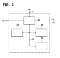
- FIG. 3 shows an exemplary structure as a block diagram the program-controlled bus components BL1 and BL2, the are realized by a conventional microprocessor unit.
- a CPU 20 communicates via an internal processor bus system 25 with a data memory 21 and a program memory 22 as well as with an I / O unit 23, which is the interface to the LIN bus system 1.
- the actuators A1, A2, A3, ... On and the sensors S1, S2 can be the same or have a similar structure.
- blower controllers e.g. a front blower regulator BL1
- another blower controller e.g. a rear blower regulator applicable if they are built identically, the same fan motors control and get the same parameters.
- the Front blower controller its blower motor e.g. for a different Can control speed.
- the protective functions e.g. Motor current limitation, power limitation, temperature limitation in air conditioning fans of a motor vehicle interior air conditioning dynamic to changing environmental conditions and operating conditions of the motor vehicle adapted become.
- the vehicle climate control unit M the necessary to adapt the protective functions Information evaluated and then by the invention Parameterization procedure via the LIN bus 1 Parameter data for dynamic adaptation of the protective functions in the blower controller BL1 or BL2, i.e. that the protective functions therein in a predetermined manner the environmental conditions and / or operating conditions of the motor vehicle to be adjusted.
- the application example below describes an example for product property selection through permanent Transmission of the selection parameters by the LIN bus master, i.e. the vehicle climate control unit M, and the selection of Performance limitation characteristic for differently powerful Air conditioning fan motors and a back pressure dependent (dynamic) power limitation of the same.
- the dynamic pressure is dependent on the boundary conditions, such as. Vehicle speed, air distribution through the air conditioning, window position, etc. on.
- the Power consumption of the blower motor is strongly dependent on the dynamic pressure, because a blower motor looks like a hydraulic machine behaves.
- the invention establishes the protective functions of the blower regulator depending on dynamic pressure.
- the vehicle climate control unit provides the blower controller with information about the dynamic pressure or in case of window adjustment or change other openings in the vehicle, e.g. the vehicle roof, the back pressure to be expected.
- a 360 W air conditioning fan is installed in vehicle x.
- the vehicle climate control unit in vehicle x transmits the value 0000 in data bits D24 to D27.
- the fan controller's product properties are adapted to the conditions in vehicle x.
- a 280 W air conditioning fan is installed in vehicle y from the same manufacturer.
- the air conditioning control unit in vehicle y transmits the value 1111 in data bits D24 to D27.
- the product property of the blower regulator is adapted to the conditions in vehicle y.
- the upper line indicates the course of the setpoints and the lower line the measured or simulated course of the power values.
- the values of the power limitation characteristics shown in FIGS. 4A and 4B were based on the same blower motor. It can be clearly seen that the current consumption of the blower motor is increased at maximum dynamic pressure.
- a Vehicle interior air conditioner also several blower motors and several blower controllers BL1 and BL2, in particular included for a front blower and a rear blower.
- the address is selected, i.e. the selection between the two blower controllers BL1 and BL2 by detecting the Level at address input Addr of the supply line 2.
- the Address assignment as a front blower controller BL1 takes place, for example if during a particular bus command to be determined a high level is detected at the address input.
- the address assignment is determined on the basis of the level at the address input Addr of the blower controllers BL1, BL2 during the assembly of the system and is adopted by the bus command in the EEPROM of the blower controller.
- the identical blower controllers BL1, BL2 now react to 2 different addresses.
- blower controllers are different via the bus system Transfer product properties.
- a 360 W front air conditioning fan is installed in vehicle x.
- the climate control unit in vehicle x transmits the value 0000 in data bits D24 to D27 of the message for the front air conditioning blower controller.
- the blower controller product property is adapted to the conditions in vehicle x.
- a 185 W rear air conditioning fan is also installed in vehicle x.
- the climate control unit in vehicle x transmits the value 1111 in data bits D24 to D27 of the message for the rear air conditioning blower regulator.
- the product characteristic of the blower regulator is adapted to the conditions of the rear system in vehicle x.
- This example is a parameterization of static and dynamic product properties.
- the parameterization of the dynamic product properties is done by transferring one or more times Parameters for dynamic and static protection functions.
- D37 8 data bits: Function: Blown air temperature act. in ° C Range of values 0 ... 190 ⁇ -40 ° C to 150 ° C 4.
- Data byte D40 D41 D42 D43 D44 D45 D46 D47 25 26 27 28 29 30 31 32 LSB MSB D40 ... D43: 4 data bits: TBD function D44 ... D47: 4 data bits: Function: Value of footwell flap OPEN 0% ... 100% resolution 6.25%
- Checksummenbyte C0 C1 C2 C3 C4 C5 C6 C7 33 34 35 36 37 38 39 40 LSB MSB C0 ... C7: 8 data bits: ADD checksum with carry inverted via data bytes 1 to 4
- a maximum temperature of 90 ° C is permissible for the fan controller. If the blown air temperature is above 50 ° C, the permissible maximum temperature in the range of 50 ° C to 60 ° C is increased linearly by 20K. The increase is also assessed by the position of the air recirculation flap and footwell flap. The maximum value of 20K is only achieved with 100% air circulation and 100% footwell OPEN. The evaluation of the air recirculation flap and the footwell flap leads to a linear decrease of 5K in the range between 100% and 70%.
- the protective function is improved by switching off the temperature.
- the fan speed is regulated to a lower maximum permissible temperature.
- the current consumption of the air conditioning fan is among others depending on the tolerance position of the blower motor, the version the air conditioning and the vehicle variant.
- the individual motor characteristic of the blower motor is measured. The evaluation depends on the environmental conditions (e.g. dynamic pressure, temperature).
- the Protective functions are attached to the motor that is actually installed customized.
- the required information is sent via data transfer (e.g. bus system, CAN) transmitted by a control device.
- data transfer e.g. bus system, CAN
- This information may only be indirect available.
- the method according to the invention is preferred here for parameterization of bus components of a vehicle interior air conditioning system using a LIN bus system and uses its standardized data structure. Instead can also bus components of other control structures with the parameterization method according to the invention using a master / slave bus structure can be parameterized.
Abstract
Description
Die Erfindung betrifft ein Verfahren zur Parametrisierung von Buskomponenten, die als programmgesteuerte Slave-Einheiten durch ein Bussystem mit Master-Slave-Struktur mit einer Master-Einheit in Verbindung treten können, und auch ein System zur Parametrisierung von Komponenten eines Kraftfahrzeuginnenraumklimatisierungssystems bildenden Slave-Einheiten, die als programmgesteuerte Buskomponenten durch ein Bussystem, z.B. einen LIN-Bus auf Grund eines entsprechenden Busdatenprotokolls mit einer als Master-Einheit fungierenden programmgesteuerten Fahrzeugklimaregeleinheit kommunizieren.The invention relates to a method for parameterization of bus components acting as program-controlled slave units through a bus system with a master-slave structure can connect to a master unit, and also a system for parameterizing components of a Motor vehicle interior air conditioning system-forming slave units, the as program-controlled bus components through a bus system, e.g. a LIN bus because of one corresponding bus data protocol with a master unit functioning program-controlled vehicle climate control unit communicate.
Derzeit werden zur Prozesssteuerung auch im Kraftfahrzeug programmgesteuerte elektronische Komponenten in busvernetzten Systemen eingesetzt. Ein Beispiel hierfür ist die Kraftfahrzeuginnenraumklimatisierung, bei der eine programmgesteuerte Fahrzeugklimaregeleinheit mit programmgesteuerten Gebläsereglern, Stelleinheiten und Sensoreinheiten über einen LIN-Bus kommuniziert. Bislang wurden die Buskomponenten am Bandende, d.h. nach Abschluss der vollständigen Ausrüstung des Kraftfahrzeugs mit dem Innenraumklimatisierungssystem parametrisiert. Dadurch wurde eine Anpassung an die kraftfahrzeugspezifischen Eigenschaften vorgenommen. Dies hat den Nachteil, dass z.B. bei der Ersatzteillogistik von den Werkstätten die Buskomponenten fahrzeugspezifisch auf Lager gehalten oder in der Werkstatt programmiert werden mussten.Process control is currently also used in motor vehicles program-controlled electronic components in bus networks Systems used. An example of this is the Motor vehicle interior air conditioning, in which a program-controlled Vehicle climate control unit with program-controlled Blower controllers, actuators and sensor units communicates via a LIN bus. So far, the Bus components at the end of the line, i.e. after completing the full Equipment of the motor vehicle with the interior air conditioning system parameterized. This made one Adaptation to the vehicle-specific properties performed. This has the disadvantage that e.g. in spare parts logistics from the workshops the bus components vehicle-specific kept in stock or in the workshop had to be programmed.
Weiterhin wurden bislang Geräteschutzfunktionen, wie z.B. Motorstrombegrenzung, Leistungsbegrenzung und/oder Temperaturbegrenzung bei Klimagebläsen der Kraftfahrzeuginnenraumklimatisierung nur statisch vorgegeben. Derartige Schutzfunktionen sind in bisherigen Kraftfahrzeuginnenraumklimatisierungssystemen so ausgelegt, dass sie im Fahrzeug unter allen zulässigen Umgebungsbedingungen, wie Fahrzeugzustand, Toleranzlage, nicht ansprechen. Dies bedingt, dass für verschiedene Fahrzeugtypen unterschiedliche statische Schutzfunktionen vorgegeben und die Gebläsemotoren, die Zuheizsysteme und die ihnen zugeordneten Regeleinheiten häufig überdimensioniert werden mussten.Device protection functions such as e.g. Motor current limitation, power limitation and / or temperature limitation with air conditioning fans of the vehicle interior air conditioning only specified statically. Such protective functions are in previous vehicle interior air conditioning systems designed to fit in the vehicle all permissible environmental conditions, such as vehicle condition, Tolerance, do not respond. This means that for different Vehicle types different static protection functions specified and the blower motors, the auxiliary heating systems and the control units assigned to them frequently had to be oversized.
Angesichts der oben angeführten Nachteile der bisherigen Verfahren und Systeme ist es Aufgabe der Erfindung, ein Verfahren und ein System zur Parametrisierung von Buskomponenten, insbesondere von Buskomponenten der KFZ-Innenraumklimatisierung, anzugeben, welche es gestatten, dass fahrzeugübergreifende identische Buskomponenten hergestellt und als Ersatzteile gelagert werden, die in der Applikation ohne zusätzliche Maßnahmen systemspezifisch bzw. kraftfahrzeugspezifisch konfiguriert werden können.Given the above disadvantages of the previous Methods and systems are the object of the invention Method and system for parameterizing bus components, in particular of bus components for vehicle interior air conditioning, indicate which allow that identical cross-vehicle bus components are manufactured and stored as spare parts in the application system-specific or without additional measures can be configured specifically for the vehicle.
Der wesentliche Aspekt des erfindungsgemäßen Verfahrens ist die Einführung eines Parametrisierungsschritts durch den den Buskomponenten von der Master-Einheit individuelle Parameter einprogrammiert werden. Dieser Parametrisierungsschritt findet innerhalb des Datenprotokolls des Master-Slave-Bussystems, z.B. LIN-Bussystems, für jede Buskomponente abhängig von der Systemkonfiguration einmalig oder mehrfach und/oder zyklisch statt.The essential aspect of the method according to the invention is the introduction of a parameterization step by the individual parameters for the bus components from the master unit be programmed. This parameterization step takes place within the data protocol of the master-slave bus system, e.g. LIN bus system, for every bus component once or depending on the system configuration repeatedly and / or cyclically.
Durch den erfindungsgemäßen Parametrisierungsschritt können somit die benötigten fahrzeugspezifischen Eigenschaften an die Buskomponenten erst bei ihrem Einbau oder Austausch übertragen werden. Dadurch braucht keine Bandende- oder Variantenprogrammierung vorgenommen werden. Es können fahrzeugübergreifende identische Buskomponenten hergestellt werden, die durch den Parametrisierungsschritt in der Applikation ohne zusätzliche Maßnahmen systemspezifisch konfiguriert werden.Through the parameterization step according to the invention thus the required vehicle-specific properties the bus components only when they are installed or replaced be transmitted. This means that no end of tape or variant programming is required be made. It can be cross-vehicle identical bus components manufactured through the parameterization step in the application System-specifically configured without additional measures become.
Insbesondere bei Einsatz von ASICs (applikationsspezifische ICs) hat das erfindungsgemäße Verfahren Vorteile, da die Eigenschaften von ASICs nachträglich im Fahrzeug gezielt verändert werden können.Especially when using ASICs (application-specific ICs), the method according to the invention has advantages because the Properties of ASICs subsequently targeted in the vehicle can be changed.
Die Parameterdaten brauchen in der Buskomponente nicht dauerhaft gespeichert werden, da sie spätestens bei jedem Neustart des Fahrzeugs oder öfter übertragen werden. Dadurch kann ein bei der Bandende-Programmierung sonst notwendiger Festwert- oder Haltespeicher in der Buskomponente entfallen.The parameter data does not need to be permanent in the bus component be saved, as they are at the latest with each restart of the vehicle or more often. Thereby may be otherwise necessary when programming the end of the tape Fixed value or hold memories in the bus component are not required.
Im Ersatzteilwesen müssen von den Werkstätten die Komponenten nicht mehr fahrzeugspezifisch programmiert werden. Es können systemübergreifend identische Ersatzteile verwendet werden.In the spare parts business, the components must be from the workshops can no longer be programmed vehicle-specifically. It can use identical spare parts across systems become.
Die Parametrisierung der Buskomponente durch die Master-Einheit kann ereignisgetriggert durchgeführt werden, wobei ein Beispiel für ein solches Ereignis jeder Neustart des Motors oder auch der Innenraumklimatisierung sein kann.The parameterization of the bus component by the master unit can be triggered by events, whereby an example of such an event each time you restart the Motor or the interior air conditioning can be.
Bevorzugt wird das erfindungsgemäße Verfahren für die Parametrisierung von Buskomponenten der Kraftfahrzeuginnenraumklimatisierung verwendet. Dabei ist die Master-Einheit eine Fahrzeugklimaregeleinheit und das Bussystem bevorzugt ein LIN-Bussystem.The method according to the invention is preferred for parameterization of bus components for vehicle interior air conditioning used. The master unit is one Vehicle climate control unit and the bus system are preferred LIN bus system.
Bei der Parametrisierung können durch die Master-Einheit zum einen statische Parameter an eine jeweilige Buskomponente übertragen werden und zum anderen dynamisch veränderbare Parameter.When parameterizing, the master unit on the one hand static parameters to a respective bus component transmitted and on the other dynamically changeable Parameter.
Parameter, die fahrzeugspezifische Eigenschaften betreffen, können den Buskomponenten zum Zeitpunkt und am Ort ihres Einbaus in das Kraftfahrzeug übertragen werden.Parameters relating to vehicle-specific properties can the bus components at the time and place of their Installation in the motor vehicle can be transferred.
Wird, wie bevorzugt, das erfindungsgemäße Verfahren bei der Kraftfahrzeuginnenraumklimaregelung verwendet, sind die an einen Gebläseregler als Buskomponente übertragenen statischen Parameter insbesondere folgende:
- Wert der Maximalstrombegrenzung,
- Wert des Temperaturschutzes,
- Wert und Steigung der Leistungsbegrenzung für den Reglerschutz und den Motorschutz,
- Regelkonstanten für Spannungsregler,
- Regelkonstanten für Stromregler,
- Regelkonstanten für Temperaturregler,
- Verstärkungsfaktoren,
- Abgleichwerte.
- Value of the maximum current limitation,
- Value of temperature protection,
- Value and slope of the power limitation for controller protection and motor protection,
- Control constants for voltage regulators,
- Control constants for current regulators,
- Control constants for temperature controllers,
- Gains,
- Calibration values.
Im Falle, dass die Buskomponente eine Komponente eines Zuheizsystems ist, sind die dieser übertragenen statischen Daten insbesondere folgende:
- Wert des Temperaturschutzes,
- Regelkreiskonstanten,
- Verstärkungsfaktoren,
- Abgleichwerte.
- Value of temperature protection,
- Loop constants
- Gains,
- Calibration values.
Gemäß einem Teil der oben genannten Aufgabenstellung können die Schutzfunktionen, wie z.B. die Motorstrombegrenzung, Leistungsbegrenzung und Temperaturbegrenzung bei Klimagebläsen der KFZ-Innenraumklimatisierung durch das erfindungsgemäße Verfahren dynamisch verändert werden. Für derartige dynamisch veränderbare Schutzfunktionen überträgt die Fahrzeugklimaregeleinheit im Parametrisierungsschritt an einen Gebläseregler unter anderem Parameter, die einen momentanen und/oder einen zu erwartenden Staudruck angeben.According to part of the above task the protective functions, e.g. the motor current limitation, Capacity limitation and temperature limitation for air conditioning fans the vehicle interior air conditioning by the inventive Procedures are changed dynamically. For such transfers dynamically changeable protective functions the vehicle climate control unit in the parameterization step to a fan controller, among other things, parameters that a Specify the current and / or an expected dynamic pressure.
Der Staudruck stellt sich in Abhängigkeit von den Randbedingungen, wie z.B. der Fahrzeuggeschwindigkeit, der Luftverteilung durch die Klimaanlage, der Fensterstellung u.s.w ein. Die Stromaufnahme des Gebläsemotors ist stark staudruckabhängig, da der Gebläsemotor wie eine hydraulische Maschine funktioniert. Bei einer Fensterverstellung ändert sich der Staudruck, so dass dabei der bei einer Fensterverstellung zu erwartende Staudruck als Parameter an den Gebläseregler übertragen wird, so dass dieser die Schutzfunktionen entsprechend ändern kann, z.B. durch eine Änderung des Regelalgorithmus.The dynamic pressure is dependent on the boundary conditions, such as. the vehicle speed, the air distribution through the air conditioning, the window position, etc. on. The current consumption of the blower motor is strongly dependent on the dynamic pressure, because the blower motor is like a hydraulic one Machine works. With a window adjustment changes the back pressure, so that the one with a window adjustment expected back pressure as parameters to the blower regulator is transferred so that this the protective functions can change accordingly, e.g. through a change of the control algorithm.
Zur dynamischen Anpassung bzw. Änderung der Schutzfunktionen gehört auch die Anpassung an Spannungsänderungen am Gebläsemotor in Folge einer Änderung der Bordnetzspannung. Bedingt durch das Schalten von Verbrauchern und Generatorspannungsänderungen in Folge von Lastwechsel, Drehzahländerungen, Start/Stoppbetrieb des Verbrennungsmotors, Bremsenergierückspeisung u.s.w. ist die Bordnetzspannung nicht konstant. Änderungen der Bordnetzspannung sollten vom Klimagebläseregler ausgeregelt werden, so dass die Motordrehzahl unabhängig von der Bordnetzspannung wird. Zur Verbesserung der Ausregelzeit überträgt erfindungsgemäß die Fahrzeugklimaregeleinheit an den Gebläseregler einen der Änderung der Bordnetzspannung entsprechenden Parameter. Ideal ist es, wenn durch das Bordnetzenergiemanagement der Fahrzeugklimaregeleinheit bzw. dem Klimagebläseregler dieser Information im Vorhinein zur Verfügung gestellt wird.For dynamic adaptation or change of the protective functions also includes the adaptation to voltage changes on the blower motor as a result of a change in the vehicle electrical system voltage. Due to the switching of consumers and generator voltage changes as a result of load changes, speed changes, Start / stop operation of the internal combustion engine, regenerative braking energy etc. the vehicle electrical system voltage is not constant. Changes in the vehicle electrical system voltage should be made by the air conditioning fan controller be adjusted so that the engine speed becomes independent of the vehicle electrical system voltage. For improvement The vehicle climate control unit transmits the settling time according to the invention to the fan control one of the change the parameters corresponding to the vehicle electrical system voltage. ideal it is when through the vehicle electrical system energy management of the vehicle climate control unit or the climate fan controller this Information is provided in advance.
Die maximal mögliche Verlustleistung am Klimagebläse ist von der Umgebungstemperatur abhängig. Zum Schutz des Klimagebläses vor Übertemperatur ist deshalb die Kenntnis der Umgebungstemperatur erforderlich. Somit überträgt die Fahrzeugklimaregeleinheit bei einem weiteren vorteilhaften Ausführungsbeispiel einen der Umgebungstemperatur entsprechenden Parameter an den Gebläseregler. Bevorzugt ist das die Temperatur der Luft, die vom Klimagebläse angesaugt wird. Wenn, wie die Erfindung vorschlägt, derartige Größen im Vorhinein als Parameter im Parametrisierungsschritt an den Gebläseregler übertragen werden, kann der Gebläseregler eine Vorsteuerung ausführen, z.B. indem er seinen Regelalgorithmus oder die Verstärkungsfaktoren der Regelkennlinie ändert.The maximum possible power loss at the air conditioning fan is depends on the ambient temperature. To protect the climate fan before overtemperature is therefore the knowledge of Ambient temperature required. The vehicle climate control unit thus transmits in a further advantageous embodiment one corresponding to the ambient temperature Parameters to the fan controller. This is preferably the Temperature of the air drawn in by the air conditioning fan. If, as the invention proposes, such sizes in In advance as a parameter in the parameterization step to the Fan controller can be transferred, the fan controller can be a Execute feedforward control, e.g. by using his control algorithm or the gain factors of the control characteristic changes.
Bei Umgebungstemperaturen unter dem Gefrierpunkt kann ein vereister Rotor des Klimagebläses blockieren. Zur Überwindung der Blockierung wird der Anlaufstrom erhöht, so dass sich ein erhöhtes Losreißmoment ergibt. Durch die Erhöhung des Stroms erhöht sich auch die Eigenerwärmung des Motors, die zur Enteisung des Motors führt. Somit kann dem Gebläseregler, wie die Erfindung vorschägt, zur dynamischen Anpassung der Schutzfunktionen auch ein Parameter übertragen werden, der die Vereisung des Rotors bzw. dessen Stillstand angibt, um daraufhin die entsprechende Erhöhung des Anlaufstroms zu bewirken. At ambient temperatures below freezing, a Block the frozen rotor of the air conditioning fan. To overcome blocking the starting current is increased so that there is an increased breakaway torque. By increasing the electricity also increases the motor's self-heating, which leads to deicing of the engine. So the blower regulator, as the invention proposes, for dynamic adaptation of the protective functions also transfer a parameter be the icing of the rotor or its standstill indicates the corresponding increase in the starting current to effect.
Die Stromaufnahme des Klimagebläses ist unter anderen abhängig von der Toleranzlage des Gebläsemotors, der Ausführung der Klimaanlage und der Fahrzeugvariante. Die individuelle Motorkennlinie wird ausgemessen, und die Bewertung erfolgt in Abhängigkeit von den Umgebungsbedingungen, unter denen z.B. der Staudruck und die Temperatur sind. Somit können die Schutzfunktionen an den tatsächlich verbauten Gebläsemotor durch eine Parameterübertragung von der Fahrzeugklimaregeleinheit an den Gebläseregler angepasst werden.The current consumption of the air conditioning fan depends on others on the tolerance position of the blower motor, the design the air conditioning and the vehicle variant. The individual Engine characteristic is measured and the evaluation takes place depending on the environmental conditions to e.g. the dynamic pressure and the temperature are. Consequently can the protective functions on the actually installed Fan motor through a parameter transfer from the vehicle climate control unit can be adapted to the blower controller.
Möglicherweise sind die der Parametrisierung zur dynamischen Anpassung der Schutzfunktionen zu Grunde liegenden Informationen nur indirekt verfügbar. Wenn der Staudruck und/oder die Temperatur der Ansaugluft nicht sensorisch gemessen werden, können sie alternativ auch aus bekannten Fahrzeugdaten'ermittelt werden. Solche Fahrzeugdaten, die zur Ermittlung der Umgebungstemperatur für das Klimagebläse herangezogen werden können, sind z.B. die Außentemperatur, Heizwassertemperatur, Wärmetauschertemperatur, Verdampfertemperatur und/oder Innenraumtemperatur. Zur Ermittlung des Staudrucks können die Fensterstellung, die Schiebedachstellung, die Verdeckstellung bei Cabriofahrzeugen u.s.w. herangezogen werden.Possibly the parameterization for dynamic Adjustment of the protective functions underlying Information only available indirectly. If the back pressure and / or the temperature of the intake air is not measured by sensors they can alternatively also be from known Vehicle data can be determined. Such vehicle data, the to determine the ambient temperature for the air conditioning fan can be used, e.g. the outside temperature, Heating water temperature, heat exchanger temperature, evaporator temperature and / or interior temperature. To determine the Dynamic pressure can change the window position, the sunroof position, the convertible top position on convertible vehicles etc. used become.
Die Erfindung betrifft gemäß einem zweiten wesentlichen Aspekt ein System zur Parametrisierung von Komponenten eines Kraftfahrzeuginnenraumklimatisierungssystems, die als programmgesteuerte Slave-Einheiten durch einen LIN-Bus auf Grund eines LIN-Busdatenprotokolls mit einer als Master-Einheit fungierenden programmgesteuerten Fahrzeugklimaregeleinheit kommunizieren, wobei das System zur Parametrisierung durch eine das LIN-Busdatenprotokoll nutzende von der Systemkonfiguration abhängige einmalige oder mehrfache und/oder zyklische Datenübertragung von der Master-Einheit zur jeweiligen Slave-Einheit eingerichtet ist.The invention relates to a second essential Aspect of a system for parameterizing components of a Automotive interior air conditioning system, which as program-controlled slave units through a LIN bus Based on a LIN bus data protocol with one as the master unit functioning program-controlled vehicle climate control unit communicate, using the system for parameterization by using one of the LIN bus data protocols System configuration dependent single or multiple and / or cyclical data transmission from the master unit is set up for the respective slave unit.
Dabei weisen die Buskomponenten bevorzugt eine Zentralprozessoreinheit und einen Datenspeicher auf, der die empfangenen Parameterdaten nicht dauerhaft speichert. Ein derartige Datenspeicher kann z.B. ein Register sein.The bus components preferably have a central processor unit and a data memory that stores the received Parameter data is not saved permanently. Such one Data storage can e.g. be a register.
Bei dem vorgeschlagenen Parametrisierungssystem ist die Zentralprozessoreinheit der Buskomponente insbesondere dazu programmiert, die im Datenspeicher gespeicherten Parameterdaten auf jede Parameterübertragung zu aktualisieren bzw. zu überschreiben.In the proposed parameterization system, the Central processor unit of the bus component in particular for this purpose programmed, the parameter data stored in the data memory to update on every parameter transfer or overwrite.
Ferner ist die Fahrzeugklimaregeleinheit dazu,programmiert, die Parameter zum Zeitpunkt und am Ort des Einbaus der jeweiligen Buskomponente in das Kraftfahrzeug zu übertragen. Ferner kann die Fahrzeugklimaregeleinheit in einer vorteilhaften Ausführungsform dazu programmiert sein, die Parameter wenigstens bei jedem Neustart des Kraftfahrzeugs zu übertragen.Furthermore, the vehicle climate control unit is programmed to the parameters at the time and place of installation of the respective Transfer bus component into the motor vehicle. Furthermore, the vehicle climate control unit can be advantageous Embodiment to be programmed, the parameters at least every time the motor vehicle is restarted transfer.
Insgesamt sind die Fahrzeugklimaregeleinheit als Master-Einheit und der als Buskomponente eingesetzte Gebläseregler und das gleichfalls als Buskomponente eingesetzte Zuheizsystem dazu programmiert, das erfindungsgemäße Parametrisierungsverfahren auszuführen.Overall, the vehicle climate control unit as a master unit and the fan controller used as a bus component and the auxiliary heating system, which is also used as a bus component programmed the parameterization method according to the invention perform.
Mit dem erfindungsgemäßen Verfahren und System werden somit die Schutzfunktionen unter allen zulässigen Umgebungsbedingungen optimal ausgelegt, da sie dynamisch an sich verändernde Umgebungsbedingungen bzw. Betriebsbedingungen des Kraftfahrzeugs angepasst werden. Vorteilhafterweise werden dadurch Baugröße und Gewicht der Komponenten des Kraftfahrzeuginnenraumklimatisierungssystems verringert. Der Schutz für Gebläsemotor und Ansteuerelektronik wird verbessert.With the method and system according to the invention the protective functions under all permissible ambient conditions optimally designed as it is dynamically changing Ambient conditions or operating conditions of the Motor vehicle to be adjusted. Advantageously thereby the size and weight of the components of the motor vehicle interior air conditioning system reduced. The protection for fan motor and control electronics is improved.
Die obigen und weitere vorteilhafte Merkmale der Erfindung werden in der nachstehenden Beschreibung von Ausführungsund Applikationsbeispielen des erfindungsgemäßen Verfahrens und Systems noch deutlicher, wenn die Beschreibung bezogen auf die beiliegenden Zeichnungsfiguren studiert wird.The above and other advantageous features of the invention are described in the following description of embodiment and Application examples of the method according to the invention and systems even clearer when referring to the description is studied on the enclosed drawing figures.
- Figur 1 zeigt schematisch ein Blockschaltbild einer Konfiguration eines erfindungsgemäßen Beispiels eines Kraftfahrzeuginnenraumklimatisierungssystems, bei dem eine als Master fungierende Fahrzeugklimaregeleinheit durch einen LIN-Bus mit als Slave-Einheiten fungierenden Buskomponenten, wie z.B. Gebläsereglern, Sensoren und Aktuatoren verbunden ist;Figure 1 shows schematically a block diagram of a configuration an example of a motor vehicle interior air conditioning system according to the invention, where one as Master acting vehicle climate control unit by a LIN bus with bus components acting as slave units, such as. Blower controllers, sensors and actuators connected is;
- Figur 2 zeigt schematisch ein Blockdiagramm der Struktur der Master-Einheit (Fahrzeugklimaregeleinheit);Figure 2 shows schematically a block diagram of the structure the master unit (vehicle climate control unit);
- Figur 3 zeigt ein Blockschaltbild der Struktur eines Gebläsereglers, undFIG. 3 shows a block diagram of the structure of a blower regulator, and
- die Figuren 4A und 4B zeigen graphisch jeweils Resultate einer erfindungsgemäß ausgeführten dynamischen Leistungsbegrenzung eines Klimagebläsemotors jeweils ohne Staudruck und bei maximalem Staudruck.Figures 4A and 4B each show results graphically a dynamic power limitation implemented according to the invention of an air conditioning blower motor without back pressure and at maximum dynamic pressure.
Die in Figur 1 als Blockdiagramm dargestellte erfindungsgemäße Systemkonfiguration wird zur Ausführung des erfindungsgemäßen Parametrisierungsverfahrens beispielhaft für Buskomponenten eines Fahrzeuginnenraumklimatisierungssystems beschrieben.The invention shown as a block diagram in Figure 1 System configuration is used to execute the invention Parameterization procedure exemplary for Bus components of a vehicle interior air conditioning system described.
Eine als Master M fungierende Fahrzeugklimaregeleinheit ist
durch ein LIN-Bussystem 1 mit verschiedenen Stellgliedern
oder Aktuatoren A1, A2, A3, ... An, Gebläsereglern BL1, BL2
und Sensoren, z.B. einem Feuchtigkeitssensor S1 und einem
Solarsensor S2, verbunden. Die Fahrzeugklimaregeleinheit M
ist bevorzugt eine programmgesteuerte Mikroprozessoreinheit.
Dasselbe gilt für die Gebläseregler BL1 und BL2, die
dem Master M (der Fahrzeugklimaregeleinheit) als Slave-Einheiten
untergeordnet sind. Es ist zu bemerken, dass BL1
z.B. einen Frontgebläseregler und BL2 einen Heckklimagebläseregler
bezeichnen.A vehicle climate control unit that functions as Master M.
through a
Die Fahrzeugklimaregeleinheit M, die Gebläseregler BL1, BL2
und die Sensoren S1 und S2 werden von einer die Bordnetzspannung
VBATT zuführenden Speiseleitung 3 gespeist. Ferner
steht die Fahrzeugklimaregeleinheit M mit anderen Fahrzeugsteuer-/regeleinheiten
durch einen üblichen CAN-Bus 4
(Leitungen CANA, CANB) in Verbindung. Die Stellglieder A1,
A2, A3, ... An werden durch eine von der Fahrzeugklimaregeleinheit
M ausgegebene Speisespannung VB über eine Speiseleitung
2 versorgt. Gleichfalls wird diese Spannung VB auch
an die Gebläseregler BL1, BL2 angelegt und dient darin zur
Selektion der Adresse für die beiden Gebläseregler BL1 und
BL2 (Beschreibung weiter unten).The vehicle climate control unit M, the blower controllers BL1, BL2 and the sensors S1 and S2 are fed by a
Das Blockschaltbild in Figur 2 zeigt eine übliche Konfiguration
als Mikroprozessor ausgeführten programmgesteuerten
Geräts, hier der Fahrzeugklimaregeleinheit M. Letztere enthält
eine CPU 10, die über ein prozessorinternes Bussystem
15 mit einem Datenspeicher 11, einem Programmspeicher 12
und I/O-Einheiten 13 und 14 kommuniziert. Die erste I/O-Einheit
13 stellt die CAN-Busverbindung CAN A und CAN B der
fahrzeugklimaregeleinheit M zu anderen Kraftfahrzeugsteuer-
bzw. -regeleinheiten her, während die zweite I/O-Einheit 14
die Schnittstelle zum LIN-Bus bildet und die Spannung VB
ausgibt.The block diagram in FIG. 2 shows a conventional configuration of a program-controlled device designed as a microprocessor, here the vehicle climate control unit M. The latter contains a
Figur 3 zeigt als Blockschaltbild eine beispielhafte Struktur
der programmgesteuerten Buskomponenten BL1 und BL2, die
durch eine übliche Mikroprozessoreinheit realisiert sind.
Eine CPU 20 kommuniziert über ein prozessorinternes Bussystem
25 mit einem Datenspeicher 21 und einem Programmspeicher
22 sowie mit einer I/O-Einheit 23, die die Schnittstelle
zum LIN-Bussystem 1 bildet. Die Stellglieder
A1,A2,A3,...An und die Sensoren S1,S2 können die selbe oder
eine ähnliche Struktur haben.FIG. 3 shows an exemplary structure as a block diagram
the program-controlled bus components BL1 and BL2, the
are realized by a conventional microprocessor unit.
A
Durch das erfindungsgemäße Parametrisierungsverfahren ist in dem in Figur 3 dargestellten Gebläseregler BL1 bzw. BL2 kein Festwertdatenspeicher oder Haltespeicher notwendig, da die Parameterdaten in der Buskomponente, d.h. dem Gebläseregler BL1 und/oder BL2, nur zwischengespeichert werden müssen.Through the parameterization method according to the invention in the blower regulator BL1 or BL2 shown in FIG no read-only data memory or hold memory necessary because the parameter data in the bus component, i.e. the fan control BL1 and / or BL2, can only be buffered have to.
Zurück zu Figur 1, die als Blockschaltbild die Struktur des Gesamtsystems darstellt. Durch die erfindungsgemäße Parametrisierung der Buskomponenten, hier der Gebläseregler BL1, BL2, wird zunächst die Anpassung an die kraftfahrzeugspezifischen Eigenschaften vorgenommen. Diese Parametrisierung wird innerhalb des Datenprotokolls des LIN-Busses vom Master, d.h. der Fahrzeugklimaregeleinheit M, an die Buskomponente, hier den oder die Gebläseregler BL1 und/oder BL2, einmalig, mehrfach oder sogar zyklisch je nach gewünschter Systemkonfiguration übertragen.Back to Figure 1, which shows the structure of the Represents overall system. Through the parameterization according to the invention the bus components, here the BL1 blower controller, BL2, will first adapt to the vehicle specific Properties made. This parameterization is within the data protocol of the LIN bus by the master, i.e. the vehicle climate control unit M, to the bus component, here the blower regulator (s) BL1 and / or BL2, once, several times or even cyclically depending on the desired Transfer system configuration.
Die benötigten fahrzeugspezifischen Eigenschaften werden erst zum Zeitpunkt und am Ort des Einbaus an die Buskomponenten übertragen. Deshalb muss keine Bandende- oder Variantenprogrammierung vorgenommen werden, und es können deshalb fahrzeugübergreifende identische Buskomponenten hergestellt und auf Lager gehalten werden, die in der Applikation durch das erfindungsgemäße Parametrisierungsverfahren systemspezifisch konfiguriert werden. Dieses Vorgehen hat insbesondere bei der Verwendung von ASICs Vorteile, da die Eigenschaften von ASICs nachträglich im Fahrzeug gezielt verändert werden können.The vehicle-specific properties required only at the time and at the point of installation on the bus components transfer. Therefore no end of tape or variant programming is required can be made and therefore it can Cross-vehicle identical bus components manufactured and kept in stock in the application through the parameterization method according to the invention can be configured system-specifically. This approach has advantages especially when using ASICs because the Properties of ASICs subsequently targeted in the vehicle can be changed.
Nachstehend werden einige Beispiele für an die Gebläseregler BL1 und BL2 von der Fahrzeugklimaregeleinheit M über das LIN-Bussystem 1 übertragbare Parameter angeführt, ohne darauf beschränkt zu sein:
- Wert der Maximalstrombegrenzung,
- Wert des Temperaturschutzes,
- Wert und Steigung der Leistungsbegrenzung für den Reglerschutz und den Motorschutz,
- Regelkonstanten für Spannungsregler,
- Regelkonstanten für Stromregler,
- Regelkonstanten für Temperaturregler,
- Verstärkungsfaktoren,
- Abgleichwerte.
- Value of the maximum current limitation,
- Value of temperature protection,
- Value and slope of the power limitation for controller protection and motor protection,
- Control constants for voltage regulators,
- Control constants for current regulators,
- Control constants for temperature controllers,
- Gains,
- Calibration values.
Weitere, in Figur 1 nicht dargestellte, Buskomponenten, die als Slave-Einheiten fungieren, können elektrische Zuheizsysteme sein, die die gleiche interne Struktur haben können, wie sie für die Gebläseregler BL1, BL2 in Figur 3 gezeigt ist. Further bus components, not shown in FIG. 1, which Electrical auxiliary heating systems can act as slave units be that can have the same internal structure as shown for the blower regulator BL1, BL2 in Figure 3 is.
Solchen elektrischen Zuheizsystemen können insbesondere folgende Parameter von der Fahrzeugklimaregeleinheit M übertragen werden:
- Wert des Temperaturschutzes,
- Regelkreiskonstanten,
- Verstärkungsfaktoren,
- Abgleichwerte.
- Value of temperature protection,
- Loop constants
- Gains,
- Calibration values.
Obwohl dies hier nicht im Einzelnen beschrieben ist, können mit dem erfindungsgemäßen Parametriesierungsverfahren auf der grundlage der in Fig.1 gezeigten Systemstruktur und des standardisierten LIN-Busprotokolls auch Parameterdaten zur Parametrisierung an die anderen Buskomponenten A1, A2, A3, ...An und S1, S2 übertragen werden.Although this is not described in detail here, with the parameterization method according to the invention the basis of the system structure shown in Fig.1 and the standardized LIN bus protocol also parameter data for Parameterization to the other bus components A1, A2, A3, ... to and S1, S2 are transmitted.
Nachfolgend wird ein erstes Beispiel für die Applikation der LIN-Busdatenkommunikation zwischen Master M (Fahrzeugklimaregeleinheit) und Slave (Gebläseregler) BL1 bzw. BL2 mit zyklischer Parametrisierung und erhöhter Datensicherheit veranschaulicht. Es ist zu bemerken, dass die den Applikationsbeispielen zugrundegelegte Datenstruktur und die angegebenen Parameterwerte selbstveständlich nur beispielhaft sind und nur zum besseren Verständnis des erfindungsgemäßen Parametrisierungsverfahrens dienen.Below is a first example of the application the LIN bus data communication between Master M (vehicle climate control unit) and slave (blower controller) BL1 or BL2 with cyclical parameterization and increased data security illustrated. It should be noted that the application examples underlying data structure and the the specified parameter values are only examples are and only for a better understanding of the invention Parameterization procedure.
Anforderung Master-Gebläseregler (Identifier Field = 0xB1)
8-Byte-Nachricht
Funktion: Vorgabe Sollwert Motorspannung
0 ... 39: 0,0 V
40 ... 250: 2,5 V bis 13,0 V
Auflösung: 50 mV/Inc
251 ... 255: 13.0 V
Vorgabe Rampenzeitkonstante ÄUmotor/s bei UBATT 13,5 V
0 ... 15: Anlaufstrom 1 A ... 15 A Auflösung 1A
0 ... 190: Temperaturwert -40°C bis 150°C
1 ... 254: Wert Maximalstrom = Datenfeld4*0,2
= 0,2 A ... 50,8 A
- D30 ... D37:
- 8 Datenbits: Regelzeitkonstante Temperatur-regler
in s
1 ... 254: Regelzeitkonstante 1 s...254 s
- D40 ... D47:
- 8 Datenbits:
Regelzeitkonstante Stromregler 1 ... 254:Regelzeitkonstante 4 ms...1016 ms
- D70 ... D77:
- 8 Datenbits: Regelzeitkonstante Spannungsregler
1 ...254: Regelzeitkonstante 32 ms...8128 ms
Function: Specification setpoint motor voltage
0 ... 39: 0.0 V
40 ... 250: 2.5 V to 13.0 V
Resolution: 50 mV / Inc
251 ... 255: 13.0
Specification ramp time constant Ä U motor / s at U BATT 13.5 V
0 ... 15: Starting current 1 A ... 15 A resolution
0 ... 190: temperature value -40 ° C to 150 °
1 ... 254: Maximum current value =
= 0.2 A ... 50.8 A
- D30 ... D37:
- 8 data bits: Control time constant temperature controller in s
1 ... 254: Control time constant 1 s ... 254 s
- D40 ... D47:
- 8 data bits: control time constant
current controller 1 ... 254: control time constant 4 ms ... 1016 ms
- D70 ... D77:
- 8 data bits: control time constant voltage regulator
1 ... 254: Control time constant 32 ms ... 8128 ms
Es ist unmittelbar einleuchtend, dass das obige Beispiel einer zyklischen Parametrisierung eines der Gebläseregler, z.B. eines Frontgebläsereglers BL1, auch auf einen weiteren Gebläseregler BL2, z.B. einen Heckgebläseregler anwendbar ist, wenn diese identisch aufgebaut, die gleichen Gebläsemotoren ansteuern und dieselben Parameter erhalten. Dies ist natürlich nicht notwendigerweise so, d.h., dass der Frontgebläseregler seinen Gebläsemotor z.B. für eine unterschiedliche Drehzahl ansteuern kann.It is immediately obvious that the example above a cyclical parameterization of one of the blower controllers, e.g. a front blower regulator BL1, also on another BL2 blower controller, e.g. a rear blower regulator applicable if they are built identically, the same fan motors control and get the same parameters. This is of course not necessarily the case, i.e. the Front blower controller its blower motor e.g. for a different Can control speed.
Gegenüber der bisher üblichen Parametrisierung oder Variantenprogrammierung von elektronischen Komponenten im Kraftfahrzeug durch Bandendeprogrammierung derselben hat das oben anhand des Beispiels einer Kraftfahrzeuginnenraumklimatisierung beschriebene erfindungsgemäße Parametrisierungsverfahren und -system insbesondere folgende Vorteile:
- es gibt keine externe Einsatzdiagnose;
- alle Buskomponenten sind dem Master bekannt;
- das Verhalten der bekannten Buskomponente kann durch das Busprotokoll für den Einsatz in anderen Fahrzeugen angepasst werden;
- es ist eine zyklische Anpassung möglich und
- die Buskomponente braucht keinen internen veränderbaren Speicher für Initialisierungsmodus.
- there is no external application diagnosis;
- all bus components are known to the master;
- the behavior of the known bus component can be adapted by the bus protocol for use in other vehicles;
- cyclical adjustment is possible and
- the bus component does not need an internal changeable memory for initialization mode.
Wie erwähnt, können mit dem erfindungsgemäßen Parametrisierungsverfahren
und - system die Schutzfunktionen, wie z.B.
Motorstrombegrenzung, Leistungsbegrenzung, Temperaturbegrenzung
bei Klimagebläsen einer Kraftfahrzeuginnenraumklimatisierung
dynamisch an sich verändernde Umgebungsbedingungen
und Betriebsbedingungen des Kraftfahrzeugs angepasst
werden. Zu diesem Zweck werden von der Fahrzeugklimaregeleinheit
M die zur Anpassung der Schutzfunktionen notwendigen
Informationen ausgewertet und daraufhin durch das erfindungsgemäße
Parametrisierungsverfahren über den LIN-Bus
1 Parameterdaten zur dynamischen Anpassung der Schutzfunktionen
im Gebläseregler BL1 oder BL2 übertragen, d.h., dass
die Schutzfunktionen darin in vorbestimmter Weise entsprechend
den Umgebungsbedingungen und/oder Betriebsbedingungen
des Kraftfahrzeugs angepasst werden.As mentioned, using the parameterization method according to the invention
and system the protective functions, e.g.
Motor current limitation, power limitation, temperature limitation
in air conditioning fans of a motor vehicle interior air conditioning
dynamic to changing environmental conditions
and operating conditions of the motor vehicle adapted
become. For this purpose, the vehicle climate control unit
M the necessary to adapt the protective functions
Information evaluated and then by the invention
Parameterization procedure via the
Das nachstehende Applikationsbeispiel beschreibt ein Beispiel für die Produkteigenschaftsauswahl durch permanente Übertragung der Auswahlparameter durch den LIN-Busmaster, d.h. die Fahrzeugklimaregeleinheit M, und die Auswahl der Leistungsbegrenzungskennlinie für unterschiedlich leistungsstarke Klimagebläsemotoren und eine staudruckabhängige (dynamische) Leistungsbegrenzung derselben.The application example below describes an example for product property selection through permanent Transmission of the selection parameters by the LIN bus master, i.e. the vehicle climate control unit M, and the selection of Performance limitation characteristic for differently powerful Air conditioning fan motors and a back pressure dependent (dynamic) power limitation of the same.
Der Staudruck stellt sich in Abhängigkeit von den Randbedingungen, wie z.B. Fahrzeuggeschwindigkeit, Luftverteilung durch die Klimaanlage, Fensterstellung u.s.w. ein. Die Stromaufnahme des Gebläsemotors ist stark staudruckabhängig, da sich ein Gebläsemotor wie eine hydraulische Maschine verhält. Die Erfindung,legt die Schutzfunktionen des Gebläsereglers staudruckabhängig aus. Die Fahrzeugklimaregeleinheit liefert dem Gebläseregler dazu Information über den Staudruck bzw. bei Fensterverstellung oder Veränderung sonstiger Öffnungen des Fahrzeugs, wie z.B. des Fahrzeugverdecks, den zu erwartenden Staudruck.The dynamic pressure is dependent on the boundary conditions, such as. Vehicle speed, air distribution through the air conditioning, window position, etc. on. The Power consumption of the blower motor is strongly dependent on the dynamic pressure, because a blower motor looks like a hydraulic machine behaves. The invention establishes the protective functions of the blower regulator depending on dynamic pressure. The vehicle climate control unit provides the blower controller with information about the dynamic pressure or in case of window adjustment or change other openings in the vehicle, e.g. the vehicle roof, the back pressure to be expected.
Im Beispiel werden zur Erhöhung der Datensicherheit für die
Auswahlparameter mindestens 2 Bits innerhalb der Nachricht
verwendet.
Funktion: Vorgabe Sollwert Motorspannung
Funktion:
Vorgabe Rampenzeitkonstante ΔUmotor / s
D24 ... D27: 4 Datenbits:
Funktion:
Function: Specification
Function:
Specification of ramp time constant ΔU motor / s
D24 ... D27: 4 data bits:
Function:
Ein Beispiel für eine Leistungsbegrenzungskennlinie für ein
360 W
Klimagebläse ist nachstehend zu finden.An example of a power limitation characteristic for a 360 W
Air conditioning fans can be found below.
Im Fahrzeug x ist ein 360 W Klimagebläse verbaut.
Die Fahrzeugklimaregeleinheit im Fahrzeug x überträgt in
den Datenbits D24 bis D27 den Wert 0000. Die Produkteigenschaft
des Gebläsereglers wird an die Bedingungen im Fahrzeug
x angepasst.A 360 W air conditioning fan is installed in vehicle x.
The vehicle climate control unit in vehicle x transmits the value 0000 in data bits D24 to D27. The fan controller's product properties are adapted to the conditions in vehicle x.
Im Fahrzeug y des gleichen Herstellers ist ein 280 W Klimagebläse
verbaut.
Das Klimabediengerät im Fahrzeug y überträgt in den Datenbits
D24 bis D27 den Wert 1111. Die Produkteigenschaft des
Gebläsereglers wird an die Bedingungen im Fahrzeug y angepasst.A 280 W air conditioning fan is installed in vehicle y from the same manufacturer.
The air conditioning control unit in vehicle y transmits the value 1111 in data bits D24 to D27. The product property of the blower regulator is adapted to the conditions in vehicle y.
Im Ersatzteilwesen des Fahrzeugherstellers wird nur ein Gebläsereglertyp
für beide Fahrzeuge geführt.
Funktion:
Fenster- und Schiebedachstellung 0: ZU, 1: AUF (Dynamische Anpassung)
D35 ... D37: 3 Datenbits
Klappenstellung Staudruckregelung 8 Zustände
dynamischen Anpassung)In the spare parts department of the vehicle manufacturer, only one fan controller type is managed for both vehicles.
Function:
Window and sunroof position 0: CLOSED, 1: OPEN (dynamic adjustment)
D35 ... D37: 3 data bits
Damper control damper position 8 states
dynamic adjustment)
Die Leistungsbegrenzungskennlinie für das Klimagebläse wird
durch die Fahrbedingungszustände bzw. den Anlagenzustand
angepasst.
Funktion:
Funktion:
Function:
Function:
Wenn Fahrgeschwindigkeit V (D30 ... D33) > Wert V0 (D44, D45) und Schiebedach / Fenster (D34) = AUF, dann erfolgt die dynamische Anpassung der LeistungsbegrenzungIf driving speed V (D30 ... D33)> value V0 (D44, D45) and sunroof / window (D34) = OPEN, then takes place the dynamic adjustment of the power limitation
Es folgt eine Berechnungsformel für die dynamische Anhebung der Leistungsbegrenzung.A calculation formula for the dynamic increase follows the power limitation.
In den Figuren 4A und 4B sind grafisch staudruckabhängige Leistungsbegrenzungskennlinien angegeben, und zwar ohne Staudruck (P=0) und bei maximalem Staudruck (Pmax). Die obere Linie gibt darin jeweils den Verlauf der Sollwerte und die untere Linie den gemessenen oder simulierten Verlauf der Leistungswerte an. Dabei lag selbstverständlich den Werten der Leistungsbegrenzungskennlinien, die in Figur 4A und 4B dargestellt sind, derselbe Gebläsemotor zu Grunde. Es ist deutlich zu erkennen, dass bei maximalem Staudruck die Stromaufnahme des Gebläsemotors erhöht ist.FIGS. 4A and 4B graphically show performance-limiting performance-dependent characteristic curves, specifically without back pressure (P = 0) and at maximum back pressure (P max ). The upper line indicates the course of the setpoints and the lower line the measured or simulated course of the power values. Of course, the values of the power limitation characteristics shown in FIGS. 4A and 4B were based on the same blower motor. It can be clearly seen that the current consumption of the blower motor is increased at maximum dynamic pressure.
Wie schon erwähnt und in Figur 1 dargestellt, kann eine
Fahrzeuginnenraumklimaanlage auch mehrere Gebläsemotoren
und dafür mehrere Gebläseregler BL1 und BL2, insbesondere
für ein Frontgebläse und ein Heckgebläse enthalten. Dabei
erfolgt die Adressselektion, d.h. die Selektion zwischen
den beiden Gebläsereglern BL1 und BL2 durch Erkennung des
Pegels am Adresseingang Addr der Versorgungsleitung 2. Die
Adressvergabe als Frontgebläseregler BL1 erfolgt beispielsweise
wenn während eines bestimmten festzulegenden Busbefehls
ein High-Pegel am Adresseingang detektiert wird.As already mentioned and shown in Figure 1, a
Vehicle interior air conditioner also several blower motors
and several blower controllers BL1 and BL2, in particular
included for a front blower and a rear blower. there
the address is selected, i.e. the selection between
the two blower controllers BL1 and BL2 by detecting the
Level at address input Addr of the
Nachfolgend wird ein Beispiel für die Produkteigenschaftsauswahl durch permanente Übertragung der Auswahlparameter durch den LIN-Busmaster (Fahrzeugklimaregeleinheit) M und Auswahl der Leistungsbegrenzungskennlinie für unterschiedlich leistungsstarke Klimagebläsemotoren angeführt.Below is an example of product property selection through permanent transmission of the selection parameters by the LIN bus master (vehicle climate control unit) M and Selection of the power limitation characteristic for different powerful air conditioning motors listed.
Im Beispiel werden zur Erhöhung der Datensicherheit für die Auswahlparameter mindestens 2 Bits innerhalb der Nachricht verwendet.In the example, to increase data security for the Selection parameters at least 2 bits within the message used.
Die Adressvergabe wird, wie erwähnt, anhand des Pegels am
Adresseingang Addr der Gebläseregler BL1, BL2 während der
Anlagenkonfektionierung festgelegt und durch den Busbefehl
in das EEPROM des Gebläsereglers übernommen.
Die identischen Gebläseregler BL1, BL2 reagieren jetzt auf
2 verschiedene Adressen.As mentioned, the address assignment is determined on the basis of the level at the address input Addr of the blower controllers BL1, BL2 during the assembly of the system and is adopted by the bus command in the EEPROM of the blower controller.
The identical blower controllers BL1, BL2 now react to 2 different addresses.
Den Gebläsereglern werden über das Bussystem unterschiedliche Produkteigenschaften übertragen.The blower controllers are different via the bus system Transfer product properties.
Durch die Adressvergabe erfolgt gleichzeitig eine Anpassung
der statischen
Funktion:
Funktion:
Funktion:
Function: Specification
Function:
Function:
Im Fahrzeug x ist ein 360 W Front Klimagebläse verbaut.
Die Klimaregeleinheit im Fahrzeug x überträgt in den Datenbits
D24 bis D27 der Nachricht für den Frontklimagebläseregler
den Wert 0000. Die Produkteigenschaft des Gebläsereglers
wird an die Bedingungen im Fahrzeug x angepasst.A 360 W front air conditioning fan is installed in vehicle x.
The climate control unit in vehicle x transmits the value 0000 in data bits D24 to D27 of the message for the front air conditioning blower controller. The blower controller product property is adapted to the conditions in vehicle x.
Im Fahrzeug x ist gleichzeitig ein 185 W Heck Klimagebläse
verbaut.
Die Klimaregeleinheit im Fahrzeug x überträgt in den Datenbits
D24 bis D27 der Nachricht für den Heckklimagebläseregler
den Wert 1111. Die Produkteigenschaft des Gebläsereglers
wird an die Bedingungen der Heckanlage im Fahrzeug x
angepasst.A 185 W rear air conditioning fan is also installed in vehicle x.
The climate control unit in vehicle x transmits the value 1111 in data bits D24 to D27 of the message for the rear air conditioning blower regulator. The product characteristic of the blower regulator is adapted to the conditions of the rear system in vehicle x.
Im Ersatzteilwesen des Fahrzeugherstellers wird nur ein Gebläseregler
für beide Fahrzeuge geführt.
Die im Gebläseregler vorhandenen identischen Berechnungsroutinen
werden durch die Adressvergabe statisch an den
Einsatzort des Klimagebläses (Front-Heck) angepasst.
Funktion: TBD
Funktion: TBD
The identical calculation routines in the blower controller are statically adapted to the location of the air conditioning blower (front-rear) by assigning the address.
Function:
Function: TBD
Die nachfolgende Beschreibung beschreibt ein Beispiel für die Parametrisierung durch eine Initialisierungsnachricht. Dieses Beispiel ist eine Parametrisierung von statischen und dynamischen Produkteigenschaften.The following description describes an example of the parameterization by an initialization message. This example is a parameterization of static and dynamic product properties.
Die Parametrisierung der dynamischen Produkteigenschaften erfolgt durch einmaliges oder mehrmaliges Übertragen von Parametern für dynamische und statische Schutzfunktion.The parameterization of the dynamic product properties is done by transferring one or more times Parameters for dynamic and static protection functions.
Das Beispiel zeigt die Auswahl der statischen Leistungsbegrenzung
und die Eigenschaften für eine dynamische Anpassung
der Temperaturbegrenzung.
Funktion: Kennung Initialisierungsnachricht
Funktion:
Funktion:
Funktion:
Temperatur Verschiebung der Zulässigen Maxtemperatur + 0 ... 30 K
Auflösung 2 K
D34 ... D37: 4 Datenbits:
Funktion:
TBLMAX = TBL0 + Wert (D34...D37) in 0 ... 30
Funktion:
Function:
Function:
Function:
Function:
Temperature shift of the permissible maximum temperature + 0 ... 30 K.
2K resolution
D34 ... D37: 4 data bits:
Function:
TBLMAX = TBL0 + value (D34 ... D37) in 0 ... 30
Function:
Funktion: Vorgabe Sollwert Motorspannung
Funktion:
Vorgabe Rampenzeitkonstante ΔUmotor / s
D24 ... D26: 4 Datenbits:
Funktion:
Wert Umluftklappe 0 % ... 100% Auflösung 6,25%
Funktion: Blaslufttemperatur akt. in °C
Wertebereich 0 ... 190 → -40°C bis 150°C
Funktion TBD
D44 ... D47: 4 Datenbits:
Funktion:
Wert Fußraumklappe AUF 0 % ... 100% Auflösung 6,25%
Function: Specification
Function:
Specification of ramp time constant ΔU motor / s
D24 ... D26: 4 data bits:
Function:
Function: Blown air temperature act. in ° C
Range of
TBD function
D44 ... D47: 4 data bits:
Function:
Value of
Bei Blaslufttemperaturen < 50°C ist eine Maximaltemperatur
von 90°C für den Gebläseregler zulässig.
Liegt die Blaslufttemperatur über 50°C wird die zulässige
Maximaltemperatur im Bereich 50°C bis 60°C linear um 20K
angehoben.
Die Anhebung wird gleichzeitig noch durch die Stellung der
Umluftklappe und Fußraumklappe bewertet.
Der Maximalwert 20K wird nur bei 100% Umluft und 100% Fußraum
AUF erreicht.
Die Bewertung der Umluftklappe und der Fußraumklappe führt
im Bereich zwischen 100% bis 70% zu einer linearen Absenkung
um je 5K.At blown air temperatures <50 ° C, a maximum temperature of 90 ° C is permissible for the fan controller.
If the blown air temperature is above 50 ° C, the permissible maximum temperature in the range of 50 ° C to 60 ° C is increased linearly by 20K.
The increase is also assessed by the position of the air recirculation flap and footwell flap.
The maximum value of 20K is only achieved with 100% air circulation and 100% footwell OPEN.
The evaluation of the air recirculation flap and the footwell flap leads to a linear decrease of 5K in the range between 100% and 70%.
Durch die dynamische Anpassung der zulässigen Maximaltemperatur
wird die Schutzfunktion durch die Temperaturabschaltung
verbessert.
Bei niederen Umgebungstemperaturen (Blasluft) oder bei
Klappenstellungen die zu einer besseren Entwärmung des Produkts
führen wird auf eine niedrigere maximal zulässige Gebläsereglertemperatur
geregelt.Due to the dynamic adaptation of the permissible maximum temperature, the protective function is improved by switching off the temperature.
In the case of low ambient temperatures (blown air) or flap positions that lead to better heat dissipation of the product, the fan speed is regulated to a lower maximum permissible temperature.
A: Bedingt durch das Schalten von Verbrauchern und Generatorspannungsänderungen in Folge von Lastwechsel, Drehzahländerung, Start/Stop-Betrieb des Verbrennungsmotors, Bremsenenergierückspeisung u.s.w. ist die Bordnetzspannung nicht konstant. Eine Änderung der Bordnetzspannung wird vom Klimagebläseregler ausgeregelt, d.h. die Motordrehzahl ist unabhängig von der Bordnetzspannung. Zur Verbesserung der Ausregelzeit wird dem Klimagebläseregler die Änderung der Bordnetzspannung angezeigt. Das Bordnetzenergiemanagement stellt dem Klimagebläseregler diese Information idealerweise im Vorhinein zur Verfügung. Somit kann bevorstehenden Änderungen entgegengesteuert werden und gegebenenfalls der Regelalgorithmus geändert werden.A: Due to the switching of consumers and generator voltage changes as a result of load changes, speed changes, Start / stop operation of the internal combustion engine, Brake energy recovery, etc. is the vehicle electrical system voltage not constant. A change in the vehicle electrical system voltage is made by Air conditioning fan controller regulated, i.e. the engine speed is regardless of the vehicle electrical system voltage. To improve the Settling time is the change in the climate blower controller Vehicle electrical system voltage displayed. The electrical system energy management ideally provides the climate blower controller with this information available in advance. Hence, upcoming Changes are counteracted and, if necessary, the Control algorithm to be changed.
B: Bei Umgebungstemperaturen unter dem Gefrierpunkt kann der vereiste Rotor des Klimagebläses blockieren. Der Anlaufstrom wird durch eine Parametrierungsübertragung erhöht, somit ergibt sich ein erhöhtes Losreißmoment. Der Blockierstrom wird erhöht, somit erhöhte Eigenerwärmung, die zur Enteisung des Rotors führt.B: At ambient temperatures below freezing block the icy rotor of the air conditioning fan. The starting current is increased by a parameter transfer, this results in an increased breakaway torque. The Blocking current is increased, thus increased self-heating, which leads to defrosting of the rotor.
C: Die Stromaufnahme des Klimagebläses ist unter anderem abhängig von der Toleranzlage des Gebläsemotors, der Ausführung der Klimaanlage und der Fahrzeugvariante.C: The current consumption of the air conditioning fan is among others depending on the tolerance position of the blower motor, the version the air conditioning and the vehicle variant.
Die individuelle Motorkennlinie des Gebläsemotors wird ausgemessen. Die Bewertung erfolgt in Abhängigkeit von den Umgebungsbedingungen (z.B. Staudruck, Temperatur). Die Schutzfunktionen werden an den tatsächlich verbauten Motor angepasst.The individual motor characteristic of the blower motor is measured. The evaluation depends on the environmental conditions (e.g. dynamic pressure, temperature). The Protective functions are attached to the motor that is actually installed customized.
Die erforderlichen Informationen werden per Datentransfer (z.B. Bussystem, CAN) von einem Steuer/Regelgerät übermittelt. Möglicherweise sind diese Informationen nur indirekt verfügbar.The required information is sent via data transfer (e.g. bus system, CAN) transmitted by a control device. This information may only be indirect available.
D: Wenn die Werte für Staudruck und Temperatur der Ansaugluft
nicht anhand von Messwerten vorliegen, dann können
diese aus bereits bekannten Fahrzeugdaten (z.B. Außentemperatur,
Heizwassertemperatur, Wärmetauschertemperatur, Verdampfertemperatur,
Innenraumtemperatur, Luftklappenstellung,
Fahrgeschwindigkeit, Fensterstellung, Schiebedachstellung,
Verdeckstellung (Cabrio) u.s.w.) ermittelt werden.
Es ist zu bemerken, dass die obige Beschreibung beispielhaft
programmgesteuerte Buskomponenten unter Verwendung üblicher
Mikroprozessorstrukturen beschreibt. Dies dient jedoch
lediglich zur Veranschaulichung, und die Buskomponenten
können auch unter Verwendung von zustandsgesteuerten
Vorrichtungen realisiert werden.D: If the values for dynamic pressure and temperature of the intake air are not available based on measured values, then these can be derived from vehicle data that is already known (e.g. outside temperature, heating water temperature, heat exchanger temperature, evaporator temperature, interior temperature, air flap position, driving speed, window position, sunroof position, convertible top position (convertible), etc.) be determined.
It should be noted that the above description exemplifies program-controlled bus components using conventional microprocessor structures. However, this is only for illustration and the bus components can also be implemented using state-controlled devices.
Das erfindungsgemäße Verfahren wird hier bevorzugt zur Parametrisierung von Buskomponenten eines Fahrzeuginnenraumklimatisierungssystems unter Einsatz eines LIN-Bussstems und dessen standardisierter Datenstruktur verwendet. Stattdessen können auch Buskomponenten anderer Steuer/-Regelstrukturen mit dem erfindungsgemäßen Parametrisierungsverfahren unter Einsatz einer Master/Slave-Busstruktur parametrisiert werden.The method according to the invention is preferred here for parameterization of bus components of a vehicle interior air conditioning system using a LIN bus system and uses its standardized data structure. Instead can also bus components of other control structures with the parameterization method according to the invention using a master / slave bus structure can be parameterized.
Claims (39)
dadurch gekennzeichnet, dass den Buskomponenten (A1, ... An, BL1, BL2, S1, S2) individuelle Parameter von der Master-Einheit (M) durch einen Parametrisierungsschritt einprogrammiert werden und dass dieser Parametrisierungsschritt innerhalb des Datenprotokolls des Bussystems (1) von der Master-Einheit (M) für jede Buskomponente einmalig oder mehrfach und/oder zyklisch durchgeführt wird.Method for parameterizing bus components (A1, ... An, BL1, BL2, S1, S2) that communicate as program-controlled slave units with a program-controlled master unit (M) through a bus system (1) with a master-slave structure can,
characterized in that the bus components (A1, ... An, BL1, BL2, S1, S2) individual parameters are programmed by the master unit (M) through a parameterization step and that this parameterization step within the data protocol of the bus system (1) from the master unit (M) is carried out once or several times and / or cyclically for each bus component.
dadurch gekennzeichnet, dass es für die Parametrisierung von Buskomponenten (A1, ... An, BL1, BL2, S1, S2) der Kraftfahrzeuginnenraumklimatisierung verwendet wird, wobei die Master-Einheit (M) eine Fahrzeugklimaregeleinheit ist. 'Method according to one of the preceding claims,
characterized in that it is used for the parameterization of bus components (A1, ... An, BL1, BL2, S1, S2) of motor vehicle interior air conditioning, the master unit (M) being a vehicle climate control unit. '
dadurch gekennzeichnet, dass das System zur Parametrisierung der Buskomponenten durch eine das Busdatenprotokoll nutzende einmalige oder mehrfache und/oder zyklische Datenübertragung von der Master-Einheit (M) zur jeweiligen Slave-Einheit (A1, ... An, BL1, BL1, S1, S2) eingerichtet ist. System for parameterizing components of a motor vehicle interior air-conditioning system, which as program-controlled slave units (A1, ... An, BL1, BL1, S1, S2) by a bus system (1) on the basis of a corresponding bus data protocol with a master unit (M) communicate functioning program-controlled vehicle climate control unit,
characterized in that the system for parameterizing the bus components by means of one-time or multiple and / or cyclic data transmission using the bus data protocol from the master unit (M) to the respective slave unit (A1, ... An, BL1, BL1, S1, S2) is set up.
Applications Claiming Priority (2)
| Application Number | Priority Date | Filing Date | Title |
|---|---|---|---|
| DE10261736A DE10261736A1 (en) | 2002-12-30 | 2002-12-30 | Parameterization method for bus components and slave units of a master-slave bus system, e.g. a motor vehicle climate control system, whereby components are programmed using the bus data protocol, either once or repeatedly |
| DE10261736 | 2002-12-30 |
Publications (3)
| Publication Number | Publication Date |
|---|---|
| EP1439670A2 true EP1439670A2 (en) | 2004-07-21 |
| EP1439670A3 EP1439670A3 (en) | 2006-01-25 |
| EP1439670B1 EP1439670B1 (en) | 2013-01-09 |
Family
ID=32478119
Family Applications (1)
| Application Number | Title | Priority Date | Filing Date |
|---|---|---|---|
| EP03025582A Expired - Lifetime EP1439670B1 (en) | 2002-12-30 | 2003-11-08 | Method and system for parameterization of bus components |
Country Status (2)
| Country | Link |
|---|---|
| EP (1) | EP1439670B1 (en) |
| DE (1) | DE10261736A1 (en) |
Cited By (3)
| Publication number | Priority date | Publication date | Assignee | Title |
|---|---|---|---|---|
| CN100397839C (en) * | 2004-11-26 | 2008-06-25 | 浙江中科正方电子技术有限公司 | Vehicle body CAN bus controlling system |
| WO2013079315A1 (en) * | 2011-12-01 | 2013-06-06 | Robert Bosch Gmbh | Sensor transmission device and method for transmitting payload data from a plurality of sensors to a bus control device for a vehicle |
| CN104070961A (en) * | 2014-07-04 | 2014-10-01 | 上汽通用五菱汽车股份有限公司 | Method for automatically identifying automobile air conditioner configuration |
Families Citing this family (5)
| Publication number | Priority date | Publication date | Assignee | Title |
|---|---|---|---|---|
| DE602005012724D1 (en) * | 2004-12-01 | 2009-03-26 | Nxp Bv | INTERFACE AND METHOD FOR TRANSMITTING BITS TO A TWO-WIRE BUS APPLYING A LIN PROTOCOL |
| DE102005011578A1 (en) * | 2005-03-14 | 2006-09-21 | Robert Bosch Gmbh | Method and circuit arrangement for limiting the current consumption of a DC motor |
| DE102012004925B4 (en) * | 2012-03-10 | 2015-10-29 | Volkswagen Aktiengesellschaft | Method for starting up a function of a component of a vehicle and corresponding component, compound of components and vehicle |
| WO2016019938A1 (en) * | 2014-08-08 | 2016-02-11 | Gentherm Gmbh | Bus system and method for controlling the same |
| DE102014116723A1 (en) * | 2014-11-14 | 2016-05-19 | TWT GmbH | Control system for at least one means of transport |
Citations (4)
| Publication number | Priority date | Publication date | Assignee | Title |
|---|---|---|---|---|
| US6098098A (en) | 1997-11-14 | 2000-08-01 | Enhanced Messaging Systems, Inc. | System for managing the configuration of multiple computer devices |
| WO2001015920A1 (en) | 1999-09-01 | 2001-03-08 | Robert Bosch Gmbh | Air conditioning system for the passenger compartment of a motor vehicle |
| WO2002037923A2 (en) | 2000-11-08 | 2002-05-16 | Bayerische Motoren Werke Aktiengesellschaft | Data bus, particularly in vehicles |
| EP1223710A2 (en) | 2000-11-20 | 2002-07-17 | Vacon Oyj | A control system for actuators and a method for controlling actuators |
Family Cites Families (3)
| Publication number | Priority date | Publication date | Assignee | Title |
|---|---|---|---|---|
| JPH06321029A (en) * | 1993-05-19 | 1994-11-22 | Alps Electric Co Ltd | Multiplex communication system |
| DE19842593C2 (en) * | 1998-09-17 | 2001-05-03 | Abb Patent Gmbh | Method for operating a bus master on a fieldbus |
| US6460356B1 (en) * | 2001-10-02 | 2002-10-08 | Paccar Inc. | HVAC control system for a multizoned vehicle |
-
2002
- 2002-12-30 DE DE10261736A patent/DE10261736A1/en not_active Withdrawn
-
2003
- 2003-11-08 EP EP03025582A patent/EP1439670B1/en not_active Expired - Lifetime
Patent Citations (4)
| Publication number | Priority date | Publication date | Assignee | Title |
|---|---|---|---|---|
| US6098098A (en) | 1997-11-14 | 2000-08-01 | Enhanced Messaging Systems, Inc. | System for managing the configuration of multiple computer devices |
| WO2001015920A1 (en) | 1999-09-01 | 2001-03-08 | Robert Bosch Gmbh | Air conditioning system for the passenger compartment of a motor vehicle |
| WO2002037923A2 (en) | 2000-11-08 | 2002-05-16 | Bayerische Motoren Werke Aktiengesellschaft | Data bus, particularly in vehicles |
| EP1223710A2 (en) | 2000-11-20 | 2002-07-17 | Vacon Oyj | A control system for actuators and a method for controlling actuators |
Cited By (4)
| Publication number | Priority date | Publication date | Assignee | Title |
|---|---|---|---|---|
| CN100397839C (en) * | 2004-11-26 | 2008-06-25 | 浙江中科正方电子技术有限公司 | Vehicle body CAN bus controlling system |
| WO2013079315A1 (en) * | 2011-12-01 | 2013-06-06 | Robert Bosch Gmbh | Sensor transmission device and method for transmitting payload data from a plurality of sensors to a bus control device for a vehicle |
| US9767055B2 (en) | 2011-12-01 | 2017-09-19 | Robert Bosch Gmbh | Sensor transmission device and method for transmitting payload data from multiple sensors to a bus control device for a vehicle |
| CN104070961A (en) * | 2014-07-04 | 2014-10-01 | 上汽通用五菱汽车股份有限公司 | Method for automatically identifying automobile air conditioner configuration |
Also Published As
| Publication number | Publication date |
|---|---|
| EP1439670B1 (en) | 2013-01-09 |
| DE10261736A1 (en) | 2004-07-08 |
| EP1439670A3 (en) | 2006-01-25 |
Similar Documents
| Publication | Publication Date | Title |
|---|---|---|
| DE602005005108T2 (en) | Control system for a network in a vehicle | |
| DE69923593T2 (en) | CONFIGURATION PROGRAMMING OF INPUT / OUTPUT NETWORK CONNECTION UNITS IN A MULTIPLEXED MOTOR VEHICLE COMMUNICATION SYSTEM | |
| DE102012102173B4 (en) | Reconfigurable interface-based electrical architecture | |
| EP1332588B1 (en) | Data bus, particularly in vehicles | |
| DE102016113244A1 (en) | VEHICLE INTERNAL RECORDING SYSTEM | |
| DE102016109599A1 (en) | Controlling the HVAC compressor speed in a vehicle | |
| EP2137030A2 (en) | Vehicle communication system, and method for the operation of a communication system | |
| DE102017206548A1 (en) | VEHICLE, CONTROL PROCESSES THEREOF AND PERFORMANCE CONTROL DEVICE FOR A VEHICLE | |
| DE102018101357A1 (en) | COOLING FAN AND ACTIVE COOLER GRILL VALVE CONTROL | |
| WO2012076130A1 (en) | Method for operating an electrical system of a motor vehicle and bus system operating in accordance with said method | |
| DE112009000500B4 (en) | Forwarding device, communication system and communication method | |
| EP1439670A2 (en) | Method and system for parameterization of bus components | |
| DE102013205390A1 (en) | DATA DISTRIBUTION DEVICE FOR A VEHICLE | |
| DE102014205246B4 (en) | Method for controlling a hybrid drive of a vehicle | |
| DE102017111771A1 (en) | Exciter current limited power generator | |
| DE102021102278A1 (en) | MESSAGE AUTHENTICATION OF VEHICLES BY PROOF-OF-WORK | |
| DE102005038183A1 (en) | Method for operating a network | |
| DE112015003669B4 (en) | Bus system and method for its control | |
| DE60025969T2 (en) | Automotive control system and method suitable for revising the control data transfer function | |
| WO2007025841A1 (en) | Method for controlling a vehicle drive unit | |
| DE102009045975A1 (en) | Automobile control system | |
| DE112018006408T5 (en) | SYSTEMS AND METHODS FOR MIXING DRIVE CONTROL IN ELECTRIC VEHICLES | |
| DE102021111961A1 (en) | Thermal management system for an electrified motor vehicle | |
| DE102021106424A1 (en) | ELECTRIFIED VEHICLE WITH CONTROL STRATEGY TO MANAGE BATTERY AND CAB COOLING | |
| DE102020214930A1 (en) | Method and control device for secure onboard communication |
Legal Events
| Date | Code | Title | Description |
|---|---|---|---|
| PUAI | Public reference made under article 153(3) epc to a published international application that has entered the european phase |
Free format text: ORIGINAL CODE: 0009012 |
|
| AK | Designated contracting states |
Kind code of ref document: A2 Designated state(s): AT BE BG CH CY CZ DE DK EE ES FI FR GB GR HU IE IT LI LU MC NL PT RO SE SI SK TR |
|
| AX | Request for extension of the european patent |
Extension state: AL LT LV MK |
|
| PUAL | Search report despatched |
Free format text: ORIGINAL CODE: 0009013 |
|
| AK | Designated contracting states |
Kind code of ref document: A3 Designated state(s): AT BE BG CH CY CZ DE DK EE ES FI FR GB GR HU IE IT LI LU MC NL PT RO SE SI SK TR |
|
| AX | Request for extension of the european patent |
Extension state: AL LT LV MK |
|
| RIC1 | Information provided on ipc code assigned before grant |
Ipc: H04L 12/403 20060101AFI20040528BHEP Ipc: B60H 1/00 20060101ALI20051205BHEP Ipc: H04L 29/02 20060101ALI20051205BHEP |
|
| 17P | Request for examination filed |
Effective date: 20060725 |
|
| AKX | Designation fees paid |
Designated state(s): DE FR GB SE |
|
| 17Q | First examination report despatched |
Effective date: 20070606 |
|
| GRAP | Despatch of communication of intention to grant a patent |
Free format text: ORIGINAL CODE: EPIDOSNIGR1 |
|
| GRAS | Grant fee paid |
Free format text: ORIGINAL CODE: EPIDOSNIGR3 |
|
| GRAA | (expected) grant |
Free format text: ORIGINAL CODE: 0009210 |
|
| AK | Designated contracting states |
Kind code of ref document: B1 Designated state(s): DE FR GB SE |
|
| REG | Reference to a national code |
Ref country code: GB Ref legal event code: FG4D Free format text: NOT ENGLISH |
|
| REG | Reference to a national code |
Ref country code: DE Ref legal event code: R096 Ref document number: 50314659 Country of ref document: DE Effective date: 20130228 |
|
| PG25 | Lapsed in a contracting state [announced via postgrant information from national office to epo] |
Ref country code: SE Free format text: LAPSE BECAUSE OF FAILURE TO SUBMIT A TRANSLATION OF THE DESCRIPTION OR TO PAY THE FEE WITHIN THE PRESCRIBED TIME-LIMIT Effective date: 20130109 |
|
| PLBE | No opposition filed within time limit |
Free format text: ORIGINAL CODE: 0009261 |
|
| STAA | Information on the status of an ep patent application or granted ep patent |
Free format text: STATUS: NO OPPOSITION FILED WITHIN TIME LIMIT |
|
| 26N | No opposition filed |
Effective date: 20131010 |
|
| REG | Reference to a national code |
Ref country code: DE Ref legal event code: R097 Ref document number: 50314659 Country of ref document: DE Effective date: 20131010 |
|
| GBPC | Gb: european patent ceased through non-payment of renewal fee |
Effective date: 20131108 |
|
| REG | Reference to a national code |
Ref country code: FR Ref legal event code: ST Effective date: 20140731 |
|
| PG25 | Lapsed in a contracting state [announced via postgrant information from national office to epo] |
Ref country code: GB Free format text: LAPSE BECAUSE OF NON-PAYMENT OF DUE FEES Effective date: 20131108 Ref country code: FR Free format text: LAPSE BECAUSE OF NON-PAYMENT OF DUE FEES Effective date: 20131202 |
|
| REG | Reference to a national code |
Ref country code: DE Ref legal event code: R084 Ref document number: 50314659 Country of ref document: DE |
|
| REG | Reference to a national code |
Ref country code: DE Ref legal event code: R084 Ref document number: 50314659 Country of ref document: DE Effective date: 20150227 |
|
| PGFP | Annual fee paid to national office [announced via postgrant information from national office to epo] |
Ref country code: DE Payment date: 20190124 Year of fee payment: 16 |
|
| REG | Reference to a national code |
Ref country code: DE Ref legal event code: R119 Ref document number: 50314659 Country of ref document: DE |
|
| PG25 | Lapsed in a contracting state [announced via postgrant information from national office to epo] |
Ref country code: DE Free format text: LAPSE BECAUSE OF NON-PAYMENT OF DUE FEES Effective date: 20200603 |