EP1457338B1 - Methods and apparatus for preventing clogging in ink jet printer nozzles - Google Patents
Methods and apparatus for preventing clogging in ink jet printer nozzles Download PDFInfo
- Publication number
- EP1457338B1 EP1457338B1 EP04012273A EP04012273A EP1457338B1 EP 1457338 B1 EP1457338 B1 EP 1457338B1 EP 04012273 A EP04012273 A EP 04012273A EP 04012273 A EP04012273 A EP 04012273A EP 1457338 B1 EP1457338 B1 EP 1457338B1
- Authority
- EP
- European Patent Office
- Prior art keywords
- ink
- nozzle
- sub
- jet printer
- impulse
- Prior art date
- Legal status (The legal status is an assumption and is not a legal conclusion. Google has not performed a legal analysis and makes no representation as to the accuracy of the status listed.)
- Expired - Lifetime
Links
Images


Classifications
-
- C—CHEMISTRY; METALLURGY
- C09—DYES; PAINTS; POLISHES; NATURAL RESINS; ADHESIVES; COMPOSITIONS NOT OTHERWISE PROVIDED FOR; APPLICATIONS OF MATERIALS NOT OTHERWISE PROVIDED FOR
- C09D—COATING COMPOSITIONS, e.g. PAINTS, VARNISHES OR LACQUERS; FILLING PASTES; CHEMICAL PAINT OR INK REMOVERS; INKS; CORRECTING FLUIDS; WOODSTAINS; PASTES OR SOLIDS FOR COLOURING OR PRINTING; USE OF MATERIALS THEREFOR
- C09D11/00—Inks
- C09D11/30—Inkjet printing inks
-
- B—PERFORMING OPERATIONS; TRANSPORTING
- B41—PRINTING; LINING MACHINES; TYPEWRITERS; STAMPS
- B41J—TYPEWRITERS; SELECTIVE PRINTING MECHANISMS, i.e. MECHANISMS PRINTING OTHERWISE THAN FROM A FORME; CORRECTION OF TYPOGRAPHICAL ERRORS
- B41J2/00—Typewriters or selective printing mechanisms characterised by the printing or marking process for which they are designed
- B41J2/005—Typewriters or selective printing mechanisms characterised by the printing or marking process for which they are designed characterised by bringing liquid or particles selectively into contact with a printing material
- B41J2/01—Ink jet
- B41J2/135—Nozzles
- B41J2/165—Preventing or detecting of nozzle clogging, e.g. cleaning, capping or moistening for nozzles
- B41J2/16517—Cleaning of print head nozzles
- B41J2/1652—Cleaning of print head nozzles by driving a fluid through the nozzles to the outside thereof, e.g. by applying pressure to the inside or vacuum at the outside of the print head
- B41J2/16526—Cleaning of print head nozzles by driving a fluid through the nozzles to the outside thereof, e.g. by applying pressure to the inside or vacuum at the outside of the print head by applying pressure only
-
- B—PERFORMING OPERATIONS; TRANSPORTING
- B41—PRINTING; LINING MACHINES; TYPEWRITERS; STAMPS
- B41J—TYPEWRITERS; SELECTIVE PRINTING MECHANISMS, i.e. MECHANISMS PRINTING OTHERWISE THAN FROM A FORME; CORRECTION OF TYPOGRAPHICAL ERRORS
- B41J2/00—Typewriters or selective printing mechanisms characterised by the printing or marking process for which they are designed
- B41J2/005—Typewriters or selective printing mechanisms characterised by the printing or marking process for which they are designed characterised by bringing liquid or particles selectively into contact with a printing material
- B41J2/01—Ink jet
- B41J2/135—Nozzles
- B41J2/165—Preventing or detecting of nozzle clogging, e.g. cleaning, capping or moistening for nozzles
- B41J2/16517—Cleaning of print head nozzles
- B41J2/16552—Cleaning of print head nozzles using cleaning fluids
Definitions
- the present invention relates to ink jet printers and, more particularly, to methods and apparatus for preventing ink clogging in such devices.
- Ink jet printing is performed by discharging ink droplets from a print head to a substrate.
- the droplets are ejected through orifices or nozzles in the print head and are directed to the substrate to form an image thereon.
- there preferably is no contact between the printer and the substrate with ink jet printing.
- ink jet printers may be characterized as either continuous or impulse devices, depending upon the mechanism by which the ink droplets are directed to the substrate.
- continuous ink jet systems an essentially uninterrupted stream of ink is ejected from a nozzle and breaks up into droplets.
- the droplets bear an electric charge so that they can be deflected by an applied electric field which is modulated according to the particular image to be recorded.
- the electric field directs the droplets toward either the substrate or an ink re-circulating reservoir.
- image formation is controlled by selectively energizing and de-energizing, for example, a piezoelectric transducer or solenoid rather than by modulating an applied electric field.
- Ink is stored in the print head or nozzle until it is necessary to form an image on the substrate.
- the printer is then activated by print signals to apply pressure to the ink and discharge a selected number of discrete ink droplets toward the substrate.
- Patent 4,266,232 in the name of Juliana, Jr., et al ., which discloses an impulse printer wherein ink drops of substantially uniform size and spacing are generated by applying drive pulses in a mutually synchronous fashion at every one of predetermined equal intervals. The amplitude of the drive pulses is controlled so that the amplitude of the drive pulse is below that of a print signal when no drop is to be formed.
- U.S. Patent 4,459,601 in the name of Howkins, wherein a fill-before-fire mode of operation is disclosed, i.e., a pulse of predetermined length is used to initiate filling of the jet chamber and firing of a droplet occurs on the trailing edge of the pulse.
- impulse ink jet printers relate to the considerably longer intervals between print cycles. Unlike continuous ink jet printers, impulse devices typically are maintained in stand-by or quiescent modes for relatively long intervals, sometimes on the order of seconds, minutes, and even hours. During these intervals, ink is allowed to stand, thicken due to evaporation of ink components, and possibly clog the nozzles of the print head. Impulse printers may begin a printing cycle with such thickened material in place. Many of the start-up problems encountered with impulse printers are attributable to ink which has been allowed to clog the nozzles during quiescent periods.
- Ink clogging is less of a concern in continuous systems because there typically are fewer interruptions in the flow of ink and any such interruption is of considerably shorter duration. Even where ink is allowed to stand and solidify in a continuous ink jet printer, it is more easily purged due to the considerably higher pressures at which these devices operate.
- U.S. Patent 3,925,789 in the name of Kashio, discloses an ink jet recording device which comprises a timer for determining the length of a quiescent period and a means for preliminary ejecting ink from a nozzle if the quiescent period exceeds a predetermined amount of time. The ejected ink is not directed to a printing substrate but, rather, to an ink collector.
- Patent 4,540,997 in the names of Biggs, et al ., discloses an ink jet printer wherein clogging is minimized by transporting the nozzles during quiescent periods to communicate with a wash station and then ejecting ink from the nozzles into the wash station if the printer has not functioned for a predetermined period of time.
- U.S. Patent 5,329,293 in the name of Liker, discloses an ink jet printer apparatus according to the preamble of claim 1 wherein clogging is minimized by pulsing the ink in the nozzle during quiescent periods.
- the pulsing signal provided is less than the size of a pulse signal that would cause ink to eject from the nozzle.
- This techniques is referred to as sub-pulsing.
- the sub-pulsing method and apparatus are effective and efficient in preventing ink from clogging the nozzle.
- the sub-pulsing leads to constant evaporation of solvents from the ink.
- all of the ink within the nozzle may suffer an increase in viscosity during the sub-pulsing period. Eventually the viscosity may increase too much and adversely effect the operation of the printer.
- the document US-A-4,597,794 discloses a pigment type ink for use in ink jet printers.
- the conventional ink composition disclosed in document comprises a pigment particles, a glycol ether, acetone alcohol, and a polymer.
- the glycol ether, contained in the conventional composition comprises a propylene glycol methyl ether.
- an ink composition is taken into account, which satisfies (among other things) ejection stability, storage stability for a long period, and fixability.
- an ink is prepared by dispersing fine particles of pigment into an aqueous dispersion medium containing a polymer having both a hydrophilic and hydrophobic construction potion.
- polyhydric alcohols such as ethylene glycohols are incorporated in the conventional ink composition in order to improve various characteristics required of the pigment-type ink.
- the document US 4,791,165 discloses an ink composition especially suitable for thermal ink-jet printers.
- the conventional ink composition comprises a glycol, water, a polymer and a dye.
- the present invention provides methods and apparatus for preventing clogging in impulse ink jet printers. It has been found in accordance with the invention that ink clogging during quiescent periods can be prevented by providing an ink that has the property of forming a barrier of higher viscosity ink where the ink contacts the ambient air. As a result, this viscosity barrier shields the remaining ink from the effects of air exposure during the quiescent period. Thereafter, the barrier is removed by a series of sub-pulses that rehomogenize the viscosity barrier and thereby clears the nozzle.
- inkjet printers comprise at least one nozzle having an orifice for ejecting ink droplets in response to a sequence of control signals, said sequence comprising firing signals and sub-firing signals, a chamber for containing an ink in fluidic communication with the orifice so that the ink forms a barrier of high viscosity ink at the orifice whenever the nozzle is in a quiescent state, control means for generating the sequence of control signals and for controlling the amplitude of the control signals.
- the control means generates a plurality of sub-firing signals after a predetermined period of quiescence.
- the sub-firing signals have amplitudes which are effective to remove, the barrier from the orifice yet which are ineffective to eject droplets of ink therefrom.
- the control means generates a plurality of firing signals after the generation of sub-firing signals for a second predetermined period of time.
- the firing signals have amplitudes which are effective to eject droplets of ink from the nozzle; whereas the sub-firing signals have amplitudes which are effective to remove the barrier from the orifice yet which are ineffective to eject droplets of ink therefrom.
- This printer is operated by allowing the ink within the nozzle to be exposed to the ambient air during a quiescent period of a predetermined time period such that a barrier of higher viscosity forms in the ink near the orifice. Thereafter, before using the printer, a plurality of sub-pulsing signals are generated which are effective to remove the barrier yet which are ineffective to eject droplets of ink. After the barrier has been removed, a plurality of firing signals can be generated on demand to eject droplets of ink from said nozzle.
- One representative ink exhibiting the desired fast-drying properties comprises a colorant, propylene glycol methyl ether, diacetone alcohol, and at least one resin selected from the group consisting of polyester resins and styrene acrylic resins.
- the propylene glycol methyl ether comprise about 44 % by weight of the ink.
- the diacetone alcohol comprises about 40.6 % by weight of the ink.
- the polyester resin comprises about 6.3 % by weight of the ink.
- the styrene acrylic resin comprises about 1.7 % by weight of the ink.
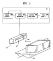
- a representative printing apparatus comprising a print head 10 having a plurality of nozzles 12 and control means 16 electrically coupled with the print head.
- print heads Any of the wide variety of print heads known in the art may be employed in the present invention, so long as it comprises at least one nozzle which ejects ink droplets in response to control signals. It is preferred that the print head be of the piezoelectric type, more preferably an MICROCODER 32/16 liquid ink jet imaging print head, which is commercially available from Trident, Inc. of Brookfield, CT.
- control means 16 may be any of those known in the art to be capable of generating control signals. As shown in Figure 1, control means 16 preferably comprises a power source 16a, a voltage or current regulator 16b, a signal generator 16c, and a timing circuit 16d for determining the interval between firing signals. It is preferred that a voltage regulator be employed and that the signal generator generate signals initiated under software control. Control means amenable to the practice of this invention include computing devices such microprocessors, microcontrollers, capacitors, switches, circuits, logic gates, or equivalent logic devices. Preferred control means 16 include a personal computer coupled to a Trident 16-Channel Analog Driver Board, part number 016-7008-01, which is commercially available from Trident, Inc.
- the preferred driver board generates a control signal in the form of an RC time constant controlled waveform with a 14.5 ⁇ second leading pulse followed by a 1.5 ⁇ second off time and a 3.5 ⁇ second trailing pulse.
- U.S. Patent Application Serial No. 08/823,718, filed March 25, 1997 and entitled "High Performance Impulse Ink Jet Method and Apparatus,” discloses firing waveforms for ejecting ink from an ink jet nozzle and includes the preferred firing pulse of the present invention.
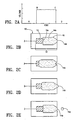
- one or more ink droplets 14c can be ejected from the nozzles 12 toward substrate 20 by selectively energizing and de-energizing piezoelectric transducers 13.
- each transducer 13 is attached to a membrane, sealant, or some other flexible member 15a in physical contact with a volume of ink 14a contained within chamber 15.
- the transducers are energized and de-energized through application of control signals.
- the control signal waveform could be selected from many known ink droplet firing signals, for brevity and simplicity of understanding, the firing control signal is shown in Figure 2A in the form of a square wave.
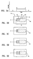
- FIGS. 3A-3E illustrated how the ink within a nozzle may react to a sub-pulse signal.
- the sub-pulse signal is typically of smaller amplitude and shorter duration than a full drop-ejecting pulse. As such, the pulse is sufficient to move the ink within the nozzle without ejecting it therefrom.
- Such a technique has been used when a printer is in a quiescent state to prevent fast drying solvent based inks from drying out and clogging the nozzle. (See for example, U.S. Pat. No.
- the present invention recognizes that allowing a fast-drying ink to dry in the nozzle forms a barrier of higher viscosity suspended solids between the nozzle orifice and the ink contained in chamber 15.
- the ink jet industry has generally tried to avoid such an effect because such a barrier would become a thick plug that would cause the nozzle to clog and operate inefficiently.
- the present invention utilizes this previously undesirable trait of fast-drying inks and uses it to a distinct advantage.
- the barrier form in such a manner as to advantageous control the evaporation of solvents within the ink.
- the result is ink within the chamber that maintains a relatively constant viscosity.
- an ink is formulated to have extremely fast-drying properties so that during the quiescent period a viscosity barrier rapidly forms at the orifice of the nozzle. Solvent and resin based inks, as described more fully, below, have demonstrated the desired properties.
- Preferred ink compositions comprise a glycol ether having a low boiling point, i.e. below 150° C, preferably a glycol alkyl ether having about 3 to 20 carbon atoms, more preferably 3-7 carbon atoms, and most preferably 4 carbon atoms.
- the preferred glycol alkyl ether is propylene glycol methyl ether.
- the glycol alkyl ether constitutes about 20 to 60 % by weight of the ink composition with about 44 % by weight being most preferred.
- Preferred ink compositions further comprise a ketone alcohol having about 1 to 10 carbon atoms.
- One preferred alcohol is diacetone alcohol. This component preferably constitutes 20 to 60 % by weight of the ink more preferably 35 to 45 %, and most preferably about 40.6 % by weight.
- the preferred ink compositions of this invention further comprise at least one resin selected from polyester resins and acrylic resins, such as styrene acrylic resin.
- the ink composition comprises about 1 to 20 % of an alcohol soluble polyester, more preferably about 5 to 10 %, and most preferably 6.3 %.
- One preferred alcohol soluble polyester is Prince 5180, manufactured by Lawter International, Northbrook, Ill.
- the ink composition preferably comprises about 1 to 10 % of a styrene acrylic polymer, more preferably 1 to 3 %, with 1.7 % being the most preferred.
- One preferred styrene acrylic polymer is Joncryl 678, available from S.C. Johnson & Son, Inc.
- Preferred ink compositions also comprise a colorant.
- the choice of colorant and its concentration principally depend on the solubility of the colorant and the intensity of its color for a particular application.
- the colorant is selected to render the ink composition visible to the human eye or some mechanical data collection device, such as a bar code scanner or other type of optical character reader.
- a preferred colorant comprises a dye such as Orasol Black RLI, which is available from Ciba-Geigy Co. of Ardsley, N.Y.
- the ink composition of this invention may further comprise one or more of the ink additives known in the art, so long as incorporation of the additives does not change the key drying properties as described in further detail below.
- the ink composition is selected so that a viscosity barrier of suspended solids, and which may actually become a solid, is allowed to form over the orifice of the nozzle during quiescent periods that exceed a predetermined time period, which is selected based on the ink formulation and other factors. Thereafter, when printing is requested, sub-pulsing is activated before printing can resume to remove the viscosity barrier by re-homogenizing it with fresh ink. While not wishing to be bound by any particular theory, it is believed that the theoretical explanation for the operation of the viscosity barrier is as described in further detail below.
- the preferred sequence of steps to employ the viscosity barrier and the sub-pulsing are shown in the flow chart of Figure 5.
- the startup sequence begins whenever a nozzle has been idle for an extended period of time (step 20).
- nozzle 12 is sub-pulsed for a predetermined period.
- the sub-pulses have a pulse width of about 1.5 ⁇ seconds and have a frequency of about 5 kHz (step 22).
- the sub-pulse amplitude is selected to move the ink yet insufficient to eject the ink from nozzle 12.
- the particular sub-pulse parameters were selected to operate effectively with the preferred ink. Other parameters may be substituted and produce similar results, particularly where the ink formulation is different from the preferred ink disclosed herein.
- the predetermined period of sub-pulsing time is the time required to ensure that the ink in the nozzle is re-homogenized with fresh ink from the chamber. It has been determined that 5 seconds is sufficient time to break-down the viscosity barrier that is formed by the preferred ink formulation described above. Of course, other re-homogenization periods could be used depending on the particular characteristics of the ink selected and the quality of operation desired.
- the print function of the nozzle is enabled (step 26). The nozzle is then available to eject droplets on demand until printing is complete and returns to a quiescent state (step 28).
Abstract
Description
- The present invention relates to ink jet printers and, more particularly, to methods and apparatus for preventing ink clogging in such devices.
- Ink jet printing is performed by discharging ink droplets from a print head to a substrate. The droplets are ejected through orifices or nozzles in the print head and are directed to the substrate to form an image thereon. In contrast to many other types of printing, there preferably is no contact between the printer and the substrate with ink jet printing.
- Most of the ink jet printers known in the art may be characterized as either continuous or impulse devices, depending upon the mechanism by which the ink droplets are directed to the substrate. In continuous ink jet systems, an essentially uninterrupted stream of ink is ejected from a nozzle and breaks up into droplets. The droplets bear an electric charge so that they can be deflected by an applied electric field which is modulated according to the particular image to be recorded. The electric field directs the droplets toward either the substrate or an ink re-circulating reservoir.
- With so-called "impulse" or "drop-on-demand" ink jet printers, image formation is controlled by selectively energizing and de-energizing, for example, a piezoelectric transducer or solenoid rather than by modulating an applied electric field. Ink is stored in the print head or nozzle until it is necessary to form an image on the substrate. The printer is then activated by print signals to apply pressure to the ink and discharge a selected number of discrete ink droplets toward the substrate.
- Because ink is ejected from impulse-type printers only periodically, these devices present a number of problems which typically are not encountered in continuous ink jet systems. These problems, which occur during the relatively short intervals between individual print signals during a single print cycle, include irregularly shaped drops and/or improper spacing of drops. The root cause of these problems may be attributable to movement of the ink meniscus at the time a print signal is generated, particularly where efforts are made to print at a frequency in excess of 3 KHz. One approach to these problems is presented by U.S. Patent 4,266,232, in the name of Juliana, Jr., et al., which discloses an impulse printer wherein ink drops of substantially uniform size and spacing are generated by applying drive pulses in a mutually synchronous fashion at every one of predetermined equal intervals. The amplitude of the drive pulses is controlled so that the amplitude of the drive pulse is below that of a print signal when no drop is to be formed. An even better approach is presented by U.S. Patent 4,459,601, in the name of Howkins, wherein a fill-before-fire mode of operation is disclosed, i.e., a pulse of predetermined length is used to initiate filling of the jet chamber and firing of a droplet occurs on the trailing edge of the pulse.
- Certain other problems associated with impulse ink jet printers relate to the considerably longer intervals between print cycles. Unlike continuous ink jet printers, impulse devices typically are maintained in stand-by or quiescent modes for relatively long intervals, sometimes on the order of seconds, minutes, and even hours. During these intervals, ink is allowed to stand, thicken due to evaporation of ink components, and possibly clog the nozzles of the print head. Impulse printers may begin a printing cycle with such thickened material in place. Many of the start-up problems encountered with impulse printers are attributable to ink which has been allowed to clog the nozzles during quiescent periods. Ink clogging is less of a concern in continuous systems because there typically are fewer interruptions in the flow of ink and any such interruption is of considerably shorter duration. Even where ink is allowed to stand and solidify in a continuous ink jet printer, it is more easily purged due to the considerably higher pressures at which these devices operate.
- A number of methods and apparatus are known in the art for preventing clogging in ink jet printers during quiescent periods. For example, U.S. Patent 4,970,527, in the name of Gatten, discloses an ink jet printer which prevents clogging by printing a few ink dots when the printer is idle. The method of Gatten, however, wastes both ink and printing substrate.
- U.S. Patent 3,925,789, in the name of Kashio, discloses an ink jet recording device which comprises a timer for determining the length of a quiescent period and a means for preliminary ejecting ink from a nozzle if the quiescent period exceeds a predetermined amount of time. The ejected ink is not directed to a printing substrate but, rather, to an ink collector. U.S. Patent 4,540,997, in the names of Biggs, et al., discloses an ink jet printer wherein clogging is minimized by transporting the nozzles during quiescent periods to communicate with a wash station and then ejecting ink from the nozzles into the wash station if the printer has not functioned for a predetermined period of time.
- U.S. Patent 5,329,293, in the name of Liker, discloses an ink jet printer apparatus according to the preamble of
claim 1 wherein clogging is minimized by pulsing the ink in the nozzle during quiescent periods. The pulsing signal provided is less than the size of a pulse signal that would cause ink to eject from the nozzle. This techniques is referred to as sub-pulsing. The sub-pulsing method and apparatus are effective and efficient in preventing ink from clogging the nozzle. However, with some extremely fast-drying inks, the sub-pulsing leads to constant evaporation of solvents from the ink. As a result, all of the ink within the nozzle may suffer an increase in viscosity during the sub-pulsing period. Eventually the viscosity may increase too much and adversely effect the operation of the printer. - The document US-A-4,597,794 discloses a pigment type ink for use in ink jet printers. The conventional ink composition disclosed in document comprises a pigment particles, a glycol ether, acetone alcohol, and a polymer. The glycol ether, contained in the conventional composition, comprises a propylene glycol methyl ether. In the prior art, an ink composition is taken into account, which satisfies (among other things) ejection stability, storage stability for a long period, and fixability. For this purpose, an ink is prepared by dispersing fine particles of pigment into an aqueous dispersion medium containing a polymer having both a hydrophilic and hydrophobic construction potion. Further, polyhydric alcohols such as ethylene glycohols are incorporated in the conventional ink composition in order to improve various characteristics required of the pigment-type ink.
- The document US 4,791,165 discloses an ink composition especially suitable for thermal ink-jet printers. In order to provide an ink composition having improved bubble formation and collapse on resistor surfaces, the conventional ink composition comprises a glycol, water, a polymer and a dye.
- Therefore, there exists a need for relatively simple methods and apparatus for preventing ink jet clogging faster drying inks which do not waste ink or printing substrate and which do not require additional devices such as ink collectors and washing stations.
- The present invention provides methods and apparatus for preventing clogging in impulse ink jet printers. It has been found in accordance with the invention that ink clogging during quiescent periods can be prevented by providing an ink that has the property of forming a barrier of higher viscosity ink where the ink contacts the ambient air. As a result, this viscosity barrier shields the remaining ink from the effects of air exposure during the quiescent period. Thereafter, the barrier is removed by a series of sub-pulses that rehomogenize the viscosity barrier and thereby clears the nozzle.
- In a preferred embodiment, inkjet printers according to the invention comprise at least one nozzle having an orifice for ejecting ink droplets in response to a sequence of control signals, said sequence comprising firing signals and sub-firing signals, a chamber for containing an ink in fluidic communication with the orifice so that the ink forms a barrier of high viscosity ink at the orifice whenever the nozzle is in a quiescent state, control means for generating the sequence of control signals and for controlling the amplitude of the control signals. The control means generates a plurality of sub-firing signals after a predetermined period of quiescence. The sub-firing signals have amplitudes which are effective to remove, the barrier from the orifice yet which are ineffective to eject droplets of ink therefrom. The control means generates a plurality of firing signals after the generation of sub-firing signals for a second predetermined period of time. The firing signals have amplitudes which are effective to eject droplets of ink from the nozzle; whereas the sub-firing signals have amplitudes which are effective to remove the barrier from the orifice yet which are ineffective to eject droplets of ink therefrom.
- This printer is operated by allowing the ink within the nozzle to be exposed to the ambient air during a quiescent period of a predetermined time period such that a barrier of higher viscosity forms in the ink near the orifice. Thereafter, before using the printer, a plurality of sub-pulsing signals are generated which are effective to remove the barrier yet which are ineffective to eject droplets of ink. After the barrier has been removed, a plurality of firing signals can be generated on demand to eject droplets of ink from said nozzle.
- One representative ink exhibiting the desired fast-drying properties comprises a colorant, propylene glycol methyl ether, diacetone alcohol, and at least one resin selected from the group consisting of polyester resins and styrene acrylic resins. The propylene glycol methyl ether comprise about 44 % by weight of the ink. The diacetone alcohol comprises about 40.6 % by weight of the ink. The polyester resin comprises about 6.3 % by weight of the ink. And, the styrene acrylic resin comprises about 1.7 % by weight of the ink.
- The numerous objects and advantages of the present invention may be better understood by those skilled in the art by reference to the accompanying figures, in which:
- Figure 1 is a diagram showing an impulse ink jet printing apparatus according to the present invention.
- Figure 2 is a diagram showing a firing signal applied to a print head nozzle and the movement of ink within the nozzle in response to the signal.
- Figure 3 is a diagram showing a sub-firing signal applied to a print head nozzle and the movement of ink within the nozzle in response to the signal.
- Figure 4 is a diagram of the barrier formed on the meniscus of the ink within the nozzle;
- Figure 5 is a flowchart of the sequence of firing and sub-firing signals.
- The methods and apparatus of the present invention can be used in conjunction with virtually any impulse or "drop-on-demand" ink jet printer which is subject to stand-by or quiescent periods. Referring to Figure 1, a representative printing apparatus according to the present invention is shown comprising a
print head 10 having a plurality ofnozzles 12 and control means 16 electrically coupled with the print head. - Any of the wide variety of print heads known in the art may be employed in the present invention, so long as it comprises at least one nozzle which ejects ink droplets in response to control signals. It is preferred that the print head be of the piezoelectric type, more preferably an
MICROCODER 32/16 liquid ink jet imaging print head, which is commercially available from Trident, Inc. of Brookfield, CT. - The control means 16 may be any of those known in the art to be capable of generating control signals. As shown in Figure 1, control means 16 preferably comprises a
power source 16a, a voltage orcurrent regulator 16b, asignal generator 16c, and atiming circuit 16d for determining the interval between firing signals. It is preferred that a voltage regulator be employed and that the signal generator generate signals initiated under software control. Control means amenable to the practice of this invention include computing devices such microprocessors, microcontrollers, capacitors, switches, circuits, logic gates, or equivalent logic devices. Preferred control means 16 include a personal computer coupled to a Trident 16-Channel Analog Driver Board, part number 016-7008-01, which is commercially available from Trident, Inc. The preferred driver board generates a control signal in the form of an RC time constant controlled waveform with a 14.5 µ second leading pulse followed by a 1.5 µ second off time and a 3.5 µ second trailing pulse. U.S. Patent Application Serial No. 08/823,718, filed March 25, 1997 and entitled "High Performance Impulse Ink Jet Method and Apparatus," discloses firing waveforms for ejecting ink from an ink jet nozzle and includes the preferred firing pulse of the present invention. - As shown in Figures 1 and 2A-2E, one or
more ink droplets 14c can be ejected from thenozzles 12 towardsubstrate 20 by selectively energizing and de-energizingpiezoelectric transducers 13. In preferred embodiments, eachtransducer 13 is attached to a membrane, sealant, or some otherflexible member 15a in physical contact with a volume ofink 14a contained withinchamber 15. The transducers are energized and de-energized through application of control signals. Although the control signal waveform could be selected from many known ink droplet firing signals, for brevity and simplicity of understanding, the firing control signal is shown in Figure 2A in the form of a square wave. - As discussed in the background section above, sub-pulsing techniques are known in the art whereby a signal of lesser amplitude is provided during quiescent periods to prevent the nozzle from clogging. Figures 3A-3E illustrated how the ink within a nozzle may react to a sub-pulse signal. As illustrated in Figure 3A, the sub-pulse signal is typically of smaller amplitude and shorter duration than a full drop-ejecting pulse. As such, the pulse is sufficient to move the ink within the nozzle without ejecting it therefrom. Such a technique has been used when a printer is in a quiescent state to prevent fast drying solvent based inks from drying out and clogging the nozzle. (See for example, U.S. Pat. No. 4,459,601 for a sub-pulsing scheme that applies pulses to the nozzle that are sufficient to move the ink within the nozzle and prevent clogging, but which are insufficient to eject ink droplets). The inventors believe, the sub-pulsing operates by constantly mixing the ink within the nozzle to maintain consistent viscosity.
- In certain printing applications, it is advantageous to have an ink which has an extremely fast drying time. For some of the more fast drying inks, the mere application of sub-pulses would eventually increase the viscosity of the ink within the nozzle to a thick, unusable state. The present invention recognizes that allowing a fast-drying ink to dry in the nozzle forms a barrier of higher viscosity suspended solids between the nozzle orifice and the ink contained in
chamber 15. The ink jet industry has generally tried to avoid such an effect because such a barrier would become a thick plug that would cause the nozzle to clog and operate inefficiently. Contradistinctly, the present invention utilizes this previously undesirable trait of fast-drying inks and uses it to a distinct advantage. In essence, by proper ink formulation, the barrier form in such a manner as to advantageous control the evaporation of solvents within the ink. The result is ink within the chamber that maintains a relatively constant viscosity. According to an aspect of the invention, an ink is formulated to have extremely fast-drying properties so that during the quiescent period a viscosity barrier rapidly forms at the orifice of the nozzle. Solvent and resin based inks, as described more fully, below, have demonstrated the desired properties. - Preferred ink compositions comprise a glycol ether having a low boiling point, i.e. below 150° C, preferably a glycol alkyl ether having about 3 to 20 carbon atoms, more preferably 3-7 carbon atoms, and most preferably 4 carbon atoms. The preferred glycol alkyl ether is propylene glycol methyl ether. Preferably, the glycol alkyl ether constitutes about 20 to 60 % by weight of the ink composition with about 44 % by weight being most preferred. Preferred ink compositions further comprise a ketone alcohol having about 1 to 10 carbon atoms. One preferred alcohol is diacetone alcohol. This component preferably constitutes 20 to 60 % by weight of the ink more preferably 35 to 45 %, and most preferably about 40.6 % by weight.
- The preferred ink compositions of this invention further comprise at least one resin selected from polyester resins and acrylic resins, such as styrene acrylic resin. Preferably, the ink composition comprises about 1 to 20 % of an alcohol soluble polyester, more preferably about 5 to 10 %, and most preferably 6.3 %. One preferred alcohol soluble polyester is Prince 5180, manufactured by Lawter International, Northbrook, Ill. The ink composition preferably comprises about 1 to 10 % of a styrene acrylic polymer, more preferably 1 to 3 %, with 1.7 % being the most preferred. One preferred styrene acrylic polymer is Joncryl 678, available from S.C. Johnson & Son, Inc.
- Preferred ink compositions also comprise a colorant. The choice of colorant and its concentration principally depend on the solubility of the colorant and the intensity of its color for a particular application. Preferably, the colorant is selected to render the ink composition visible to the human eye or some mechanical data collection device, such as a bar code scanner or other type of optical character reader. A preferred colorant comprises a dye such as Orasol Black RLI, which is available from Ciba-Geigy Co. of Ardsley, N.Y.
- One particularly preferred ink that demonstrates the desired fast-drying properties has been prepared as follows:
Propylene Glycol Methyl Ether 44.0 % Diacetone Alcohol 40.6 % Prince 5180 6.3% Joncryl 678 1.7% Orasol Black RLI 7.4% - The ink composition of this invention may further comprise one or more of the ink additives known in the art, so long as incorporation of the additives does not change the key drying properties as described in further detail below.
- In accordance with the invention, the ink composition is selected so that a viscosity barrier of suspended solids, and which may actually become a solid, is allowed to form over the orifice of the nozzle during quiescent periods that exceed a predetermined time period, which is selected based on the ink formulation and other factors. Thereafter, when printing is requested, sub-pulsing is activated before printing can resume to remove the viscosity barrier by re-homogenizing it with fresh ink. While not wishing to be bound by any particular theory, it is believed that the theoretical explanation for the operation of the viscosity barrier is as described in further detail below.
- Without sub-pulsing, a solvent concentration gradient is rapidly formed at the surface of the ink in the nozzle orifice as the volatile solvent evaporates (see Figure 4A). Formation of this viscosity gradient or
barrier 18 dramatically slows the rate of solvent loss fromnozzle 12. Unlike many inks, with a properly selected ink, such as the fonnulation described above, re-homogenization readily occurs under perturbing action of the sub-pulse. Thus, by first sub-pulsing a nozzle containing the fast-drying ink, anozzle 12 that has been dormant for an hour or more can be successfully fired again after a few seconds of sub-pulsing. - By contrast, if a constant sub-pulsing system is applied to such a fast drying ink, such as the preferred ink described above, the ink viscosity within
nozzle 12 will rise too high and produce poor print performance. In such a system, it is believed that the sub-pulsing generates eddy currents which agitate the ink innozzle 12, maintaining it homogeneity. As a result, fresh solvent is continuously being presented at the nozzle orifice and no viscosity gradient is formed. Over extended periods of sub-pulsing, the solvent level innozzle 12 becomes extremely depleted causing the viscosity of the ink to rise significantly, especially at the edges ofnozzle 12 where the sub-pulsing has the least effect (see Figure 4B). - The preferred sequence of steps to employ the viscosity barrier and the sub-pulsing are shown in the flow chart of Figure 5. The startup sequence begins whenever a nozzle has been idle for an extended period of time (step 20). After startup,
nozzle 12 is sub-pulsed for a predetermined period. Preferably, the sub-pulses have a pulse width of about 1.5 µ seconds and have a frequency of about 5 kHz (step 22). The sub-pulse amplitude is selected to move the ink yet insufficient to eject the ink fromnozzle 12. The particular sub-pulse parameters were selected to operate effectively with the preferred ink. Other parameters may be substituted and produce similar results, particularly where the ink formulation is different from the preferred ink disclosed herein. The predetermined period of sub-pulsing time is the time required to ensure that the ink in the nozzle is re-homogenized with fresh ink from the chamber. It has been determined that 5 seconds is sufficient time to break-down the viscosity barrier that is formed by the preferred ink formulation described above. Of course, other re-homogenization periods could be used depending on the particular characteristics of the ink selected and the quality of operation desired. After the 5 second period (step 24), the print function of the nozzle is enabled (step 26). The nozzle is then available to eject droplets on demand until printing is complete and returns to a quiescent state (step 28). - While the printer is active and for a period thereafter, sub-pulsing of the ink can continue to maintain a constant viscosity of the ink as with constant sub-pulsing system. That is, just as with constant sub-pulsing systems, the system disclosed herein contemplates that the printer can remain enabled with constant sub-pulsing on for some predetermined period of time without clogging the nozzle or raising the ink viscosity to an unusable level. However, if the printer remains idle for an extended period (about 15 minutes in the present example), the sub-pulsing should cease, allowing the
viscosity barrier 18 to form over the orifice (see also Figure 4A). Accordingly, a timer is set for about 15 minutes during which time printing can restart on demand (steps 30, 32). After that time has expired, sub-pulsing is stopped and restarting requires completion of the start-up sequence to re-homogenize the viscosity barrier (steps 34, 36). - Those skilled in the art will appreciate that numerous changes and modifications may be made to the preferred embodiments of the invention and that such changes and modifications may be made without departing from the invention as defined in the appended claims. For example, instead of generating control signals as in the present invention by modulating the amplitude of applied electric energy, it may be possible generate such signals by modulating applied light energy or heat. Moreover, other fast drying inks using completely different formulations could be used, so long as they exhibit the desired fast-drying properties.
Claims (12)
- An impulse ink jet printer, comprising:- at least one nozzle (12) for ejecting droplets of ink (14c) in response to firing signals having a predetermined parameter which is effective to eject ink droplets ;- a chamber (15) disposed in said nozzle (12),- an ink (14a) contained in said chamber (15);- means (16d) for determining that a quiescent period has occurred in which said ink (14a) was substantially stagnant;- means (16c), in communication with said means (16d) for determining, for generating control signals comprising the firing signals and sub-firing signals;characterized in that- said ink (14a) is a chemical solvent based ink composition comprising a colorant, a glycol ether having a boiling point below 150 °C, a ketone alcohol, and at least one resin selected from the group consisting of polyester resins and styrene acrylic resins;- wherein the chemical solvent evaporates at a rate that forms a viscosity barrier when exposed to air for a predetermined period of time such that ink (14a) disposed behind the barrier maintains a substantially constant predetermined viscosity;- said means (16c) for generating control signals is adapted to generate a plurality of sub-firing signals having a parameter which is effective to perturb the ink (14a) so that the barrier is re-homogenized into the ink (14a) yet which is ineffective to eject ink droplets, so as to remove the barrier from the nozzle (12) before ejecting droplets of ink (14a) after said means (16d) for determining determines that a quiescent period has occurred.
- The impulse ink jet printer of claim 1 wherein said predetermined parameter is at least one of time and amplitude.
- The impulse ink jet printer of claim 1 or 2 wherein said sub-firing signals have a sufficient amplitude to perturb the ink (14a) within the nozzle (12) without ejecting the ink (14a) therefrom so as to rehomogenize the ink (14a) within the nozzle (12) with fresh ink (14a) from the chamber (15).
- A method of operating an inkjet printer which comprises at least one nozzle (12) for ejecting ink droplets from an ink chamber (15) in response to a firing signals of controlled amplitude,
wherein
said ink (14a) is a chemical solvent based ink composition comprising a colorant, a glycol ether having a boiling point below 150°C, a ketone alcohol, and at least one resin selected from the group consisting of polyester resins and styrene acrylic resins; and
said method comprises the steps of:- exposing ink (14a) contained in said nozzle (12) to air such that the chemical solvent evaporates to form a viscosity barrier proximate the end of said nozzle (12) isolating the ink (14a) from the air;- generating a plurality of sub-firing signals of controlled amplitude, said sub-firing signals having a parameter which is effective to perturb the ink (14a) so that the barrier is re-homogenized into the ink (14a) yet which is ineffective to eject ink droplets; and- after the barrier has been re-homogenized, generating a firing signal having a parameter which is effective to eject ink droplets. - The method of claim 4, wherein the step of generating a plurality of sub-firing signals is performed after a quiescent period in which the ink was substantially stagnant and before the step of generating a firing signal.
- The method of claim 4 or 5, wherein the step of generating a plurality of sub-firing signals continues for at least about 5 seconds.
- The impulse ink jet printer of at least one of claims 1 to 3 or the method of at least one of claims 4 to 6, wherein the glycol ether comprises propylene glycol methyl ether.
- The impulse ink jet printer or the method of claim 7 wherein the propylene glycol methyl ether constitutes about 44 % by weight of the ink (14a).
- The impulse ink jet printer of at least one of claims I to 3, 7, 8, or the method of at least one of claims 4 to 8 wherein the ketone alcohol comprises diacetone alcohol.
- The impulse ink jet printer or the method of claim 9 wherein the diacetone alcohol constitutes about 40.6 % by weight of the ink (14a).
- The impulse ink jet printer of at least one of claims 1 to 3, 7 to 10 or the method of at least one of claims 4 to 10 wherein the ink comprises a polyester resin constituting about 6.3 % by weight of the ink (14a).
- The impulse ink jet printer of at least one of claims 1 to 3, 7 to 11 or the method of at least one of claims 4 to 11 wherein the ink comprises a styrene acrylic resin constituting about 1.7 % by weight of the ink (14a).
Applications Claiming Priority (3)
| Application Number | Priority Date | Filing Date | Title |
|---|---|---|---|
| US903016 | 1997-07-31 | ||
| US08/903,016 US20020001014A1 (en) | 1997-07-31 | 1997-07-31 | Methods and apparatus for ink capping ink jet printer nozzles |
| EP98935656A EP0998392B1 (en) | 1997-07-31 | 1998-07-15 | Methods and apparatus for ink capping ink jet printer nozzles |
Related Parent Applications (2)
| Application Number | Title | Priority Date | Filing Date |
|---|---|---|---|
| EP98935656A Division EP0998392B1 (en) | 1997-07-31 | 1998-07-15 | Methods and apparatus for ink capping ink jet printer nozzles |
| EP98935656.3 Division | 1998-07-15 |
Publications (2)
| Publication Number | Publication Date |
|---|---|
| EP1457338A1 EP1457338A1 (en) | 2004-09-15 |
| EP1457338B1 true EP1457338B1 (en) | 2006-10-18 |
Family
ID=25416789
Family Applications (3)
| Application Number | Title | Priority Date | Filing Date |
|---|---|---|---|
| EP98935656A Expired - Lifetime EP0998392B1 (en) | 1997-07-31 | 1998-07-15 | Methods and apparatus for ink capping ink jet printer nozzles |
| EP04012274A Expired - Lifetime EP1457339B1 (en) | 1997-07-31 | 1998-07-15 | Ink composition |
| EP04012273A Expired - Lifetime EP1457338B1 (en) | 1997-07-31 | 1998-07-15 | Methods and apparatus for preventing clogging in ink jet printer nozzles |
Family Applications Before (2)
| Application Number | Title | Priority Date | Filing Date |
|---|---|---|---|
| EP98935656A Expired - Lifetime EP0998392B1 (en) | 1997-07-31 | 1998-07-15 | Methods and apparatus for ink capping ink jet printer nozzles |
| EP04012274A Expired - Lifetime EP1457339B1 (en) | 1997-07-31 | 1998-07-15 | Ink composition |
Country Status (9)
| Country | Link |
|---|---|
| US (1) | US20020001014A1 (en) |
| EP (3) | EP0998392B1 (en) |
| JP (1) | JP2001512707A (en) |
| AT (3) | ATE342805T1 (en) |
| AU (1) | AU8485298A (en) |
| CA (1) | CA2296326C (en) |
| DE (3) | DE69834445T2 (en) |
| IL (2) | IL134126A0 (en) |
| WO (1) | WO1999006213A1 (en) |
Families Citing this family (3)
| Publication number | Priority date | Publication date | Assignee | Title |
|---|---|---|---|---|
| US6302536B1 (en) * | 1997-07-31 | 2001-10-16 | Trident International, Inc. | Fast drying ink jet ink compositions for capping ink jet printer nozzles |
| US6444019B1 (en) | 1998-11-06 | 2002-09-03 | Videojet Technologies Inc. | Ink jet ink composition |
| US6726756B1 (en) | 2000-05-26 | 2004-04-27 | Videojet Technologies Inc. | Continuous ink jet printing ink composition |
Citations (2)
| Publication number | Priority date | Publication date | Assignee | Title |
|---|---|---|---|---|
| US4791165A (en) * | 1985-07-18 | 1988-12-13 | Hewlett-Packard Company | Ink-jet ink for plain paper printing |
| US5329293A (en) * | 1991-04-15 | 1994-07-12 | Trident | Methods and apparatus for preventing clogging in ink jet printers |
Family Cites Families (10)
| Publication number | Priority date | Publication date | Assignee | Title |
|---|---|---|---|---|
| US3925789A (en) | 1971-12-16 | 1975-12-09 | Casio Computer Co Ltd | Ink jet recording apparatus |
| JPS51137506A (en) * | 1975-05-22 | 1976-11-27 | Konishiroku Photo Ind | Composition of ink for ink jet recording |
| US4266232A (en) | 1979-06-29 | 1981-05-05 | International Business Machines Corporation | Voltage modulated drop-on-demand ink jet method and apparatus |
| DE3115532A1 (en) * | 1980-04-17 | 1982-01-28 | Canon K.K., Tokyo | INK-JET RECORDING METHOD AND RECORDING INK FOR RECORDING ON AN IMAGE RECEIVER |
| US4459601A (en) | 1981-01-30 | 1984-07-10 | Exxon Research And Engineering Co. | Ink jet method and apparatus |
| US4540997A (en) | 1984-03-26 | 1985-09-10 | Tektronix, Inc. | Method and apparatus for avoiding the drying of ink in the ink jets of ink jet printers |
| US4970527A (en) | 1988-12-02 | 1990-11-13 | Spectra-Physics, Incorporated | Priming method for inkjet printers |
| US5160535A (en) * | 1991-01-11 | 1992-11-03 | Trident, Inc. | Rapidly drying impulse ink jet ink compositions |
| US5154761A (en) * | 1991-01-28 | 1992-10-13 | Trident, Inc. | High definition impulse ink jet in compositions |
| JP3123195B2 (en) * | 1992-04-15 | 2001-01-09 | ミノルタ株式会社 | Inkjet recording liquid |
-
1997
- 1997-07-31 US US08/903,016 patent/US20020001014A1/en not_active Abandoned
-
1998
- 1998-07-15 EP EP98935656A patent/EP0998392B1/en not_active Expired - Lifetime
- 1998-07-15 AT AT04012273T patent/ATE342805T1/en not_active IP Right Cessation
- 1998-07-15 EP EP04012274A patent/EP1457339B1/en not_active Expired - Lifetime
- 1998-07-15 CA CA002296326A patent/CA2296326C/en not_active Expired - Fee Related
- 1998-07-15 DE DE69834445T patent/DE69834445T2/en not_active Expired - Fee Related
- 1998-07-15 EP EP04012273A patent/EP1457338B1/en not_active Expired - Lifetime
- 1998-07-15 WO PCT/US1998/014574 patent/WO1999006213A1/en active IP Right Grant
- 1998-07-15 IL IL13412698A patent/IL134126A0/en active IP Right Grant
- 1998-07-15 AU AU84852/98A patent/AU8485298A/en not_active Abandoned
- 1998-07-15 AT AT98935656T patent/ATE309910T1/en not_active IP Right Cessation
- 1998-07-15 DE DE69832385T patent/DE69832385T2/en not_active Expired - Fee Related
- 1998-07-15 JP JP2000505004A patent/JP2001512707A/en active Pending
- 1998-07-15 AT AT04012274T patent/ATE324985T1/en not_active IP Right Cessation
- 1998-07-15 DE DE69836233T patent/DE69836233D1/en not_active Expired - Lifetime
-
2000
- 2000-01-19 IL IL134126A patent/IL134126A/en not_active IP Right Cessation
Patent Citations (2)
| Publication number | Priority date | Publication date | Assignee | Title |
|---|---|---|---|---|
| US4791165A (en) * | 1985-07-18 | 1988-12-13 | Hewlett-Packard Company | Ink-jet ink for plain paper printing |
| US5329293A (en) * | 1991-04-15 | 1994-07-12 | Trident | Methods and apparatus for preventing clogging in ink jet printers |
Also Published As
| Publication number | Publication date |
|---|---|
| IL134126A0 (en) | 2001-04-30 |
| JP2001512707A (en) | 2001-08-28 |
| DE69834445D1 (en) | 2006-06-08 |
| EP0998392B1 (en) | 2005-11-16 |
| DE69832385D1 (en) | 2005-12-22 |
| CA2296326C (en) | 2004-01-20 |
| ATE309910T1 (en) | 2005-12-15 |
| EP1457339B1 (en) | 2006-05-03 |
| DE69832385T2 (en) | 2006-06-01 |
| EP1457339A1 (en) | 2004-09-15 |
| WO1999006213A1 (en) | 1999-02-11 |
| US20020001014A1 (en) | 2002-01-03 |
| EP1457338A1 (en) | 2004-09-15 |
| DE69836233D1 (en) | 2006-11-30 |
| IL134126A (en) | 2006-10-05 |
| ATE324985T1 (en) | 2006-06-15 |
| EP0998392A4 (en) | 2000-05-10 |
| EP0998392A1 (en) | 2000-05-10 |
| ATE342805T1 (en) | 2006-11-15 |
| DE69834445T2 (en) | 2006-09-14 |
| CA2296326A1 (en) | 1999-02-11 |
| AU8485298A (en) | 1999-02-22 |
Similar Documents
| Publication | Publication Date | Title |
|---|---|---|
| EP1059340B1 (en) | Fast drying ink jet ink compositions for capping ink jet printer nozzles | |
| US5329293A (en) | Methods and apparatus for preventing clogging in ink jet printers | |
| KR920004163A (en) | Inkjet recording device using heat energy and its recovery method | |
| GB2159465A (en) | Generating droplets by heating | |
| JPH0929996A (en) | Ink jet recording method | |
| EP1457338B1 (en) | Methods and apparatus for preventing clogging in ink jet printer nozzles | |
| JP3671998B2 (en) | Inkjet recording device | |
| US5483266A (en) | Ink jet recording apparatus with two storage modes | |
| WO2006107494A1 (en) | Inkjet ink for porous and non-porous printing | |
| US6357852B1 (en) | Method and apparatus for restoring an ink jet printhead | |
| JPH06126973A (en) | Method for removing foreign particle on heating means of thermal ink jet printer | |
| JPH09141882A (en) | Ink jet recording method and apparatus | |
| JPH07178929A (en) | Method and apparatus for ink jet recording and data processing device | |
| JP3095905B2 (en) | Clogging prevention mechanism | |
| JPH08169124A (en) | Ink jet recording apparatus | |
| JP3103590B2 (en) | Ink jet recording apparatus and recording method in the apparatus | |
| JPH11192727A (en) | Ink jet printer | |
| JPH1016222A (en) | Ink jet recorder | |
| JP3291490B2 (en) | Clogging prevention mechanism | |
| JPH03256749A (en) | Ink jet recorder | |
| JPH10286947A (en) | Ink jet recording method | |
| JPS5985765A (en) | Ink jet recording apparatus | |
| JPS63172657A (en) | Ink jet recording apparatus | |
| JP2007152668A (en) | Recovering method for inkjet recording head, and inkjet recording device | |
| JPS58167170A (en) | Ink jet recorder |
Legal Events
| Date | Code | Title | Description |
|---|---|---|---|
| PUAI | Public reference made under article 153(3) epc to a published international application that has entered the european phase |
Free format text: ORIGINAL CODE: 0009012 |
|
| 17P | Request for examination filed |
Effective date: 20040525 |
|
| AC | Divisional application: reference to earlier application |
Ref document number: 0998392 Country of ref document: EP Kind code of ref document: P |
|
| AK | Designated contracting states |
Kind code of ref document: A1 Designated state(s): AT CH DE ES FI FR GB IE IT LI NL SE |
|
| AKX | Designation fees paid |
Designated state(s): AT CH DE ES FI FR GB IE IT LI NL SE |
|
| 17Q | First examination report despatched |
Effective date: 20050602 |
|
| RAP1 | Party data changed (applicant data changed or rights of an application transferred) |
Owner name: ILLINOIS TOOL WORKS INC. |
|
| GRAP | Despatch of communication of intention to grant a patent |
Free format text: ORIGINAL CODE: EPIDOSNIGR1 |
|
| GRAS | Grant fee paid |
Free format text: ORIGINAL CODE: EPIDOSNIGR3 |
|
| GRAA | (expected) grant |
Free format text: ORIGINAL CODE: 0009210 |
|
| AC | Divisional application: reference to earlier application |
Ref document number: 0998392 Country of ref document: EP Kind code of ref document: P |
|
| AK | Designated contracting states |
Kind code of ref document: B1 Designated state(s): AT CH DE ES FI FR GB IE IT LI NL SE |
|
| PG25 | Lapsed in a contracting state [announced via postgrant information from national office to epo] |
Ref country code: IT Free format text: LAPSE BECAUSE OF FAILURE TO SUBMIT A TRANSLATION OF THE DESCRIPTION OR TO PAY THE FEE WITHIN THE PRESCRIBED TIME-LIMIT;WARNING: LAPSES OF ITALIAN PATENTS WITH EFFECTIVE DATE BEFORE 2007 MAY HAVE OCCURRED AT ANY TIME BEFORE 2007. THE CORRECT EFFECTIVE DATE MAY BE DIFFERENT FROM THE ONE RECORDED. Effective date: 20061018 Ref country code: LI Free format text: LAPSE BECAUSE OF FAILURE TO SUBMIT A TRANSLATION OF THE DESCRIPTION OR TO PAY THE FEE WITHIN THE PRESCRIBED TIME-LIMIT Effective date: 20061018 Ref country code: FI Free format text: LAPSE BECAUSE OF FAILURE TO SUBMIT A TRANSLATION OF THE DESCRIPTION OR TO PAY THE FEE WITHIN THE PRESCRIBED TIME-LIMIT Effective date: 20061018 Ref country code: AT Free format text: LAPSE BECAUSE OF FAILURE TO SUBMIT A TRANSLATION OF THE DESCRIPTION OR TO PAY THE FEE WITHIN THE PRESCRIBED TIME-LIMIT Effective date: 20061018 Ref country code: NL Free format text: LAPSE BECAUSE OF FAILURE TO SUBMIT A TRANSLATION OF THE DESCRIPTION OR TO PAY THE FEE WITHIN THE PRESCRIBED TIME-LIMIT Effective date: 20061018 Ref country code: CH Free format text: LAPSE BECAUSE OF FAILURE TO SUBMIT A TRANSLATION OF THE DESCRIPTION OR TO PAY THE FEE WITHIN THE PRESCRIBED TIME-LIMIT Effective date: 20061018 |
|
| REG | Reference to a national code |
Ref country code: GB Ref legal event code: FG4D |
|
| REG | Reference to a national code |
Ref country code: CH Ref legal event code: EP Ref country code: IE Ref legal event code: FG4D |
|
| REF | Corresponds to: |
Ref document number: 69836233 Country of ref document: DE Date of ref document: 20061130 Kind code of ref document: P |
|
| PG25 | Lapsed in a contracting state [announced via postgrant information from national office to epo] |
Ref country code: SE Free format text: LAPSE BECAUSE OF FAILURE TO SUBMIT A TRANSLATION OF THE DESCRIPTION OR TO PAY THE FEE WITHIN THE PRESCRIBED TIME-LIMIT Effective date: 20070118 |
|
| PG25 | Lapsed in a contracting state [announced via postgrant information from national office to epo] |
Ref country code: DE Free format text: LAPSE BECAUSE OF FAILURE TO SUBMIT A TRANSLATION OF THE DESCRIPTION OR TO PAY THE FEE WITHIN THE PRESCRIBED TIME-LIMIT Effective date: 20070119 |
|
| PG25 | Lapsed in a contracting state [announced via postgrant information from national office to epo] |
Ref country code: ES Free format text: LAPSE BECAUSE OF FAILURE TO SUBMIT A TRANSLATION OF THE DESCRIPTION OR TO PAY THE FEE WITHIN THE PRESCRIBED TIME-LIMIT Effective date: 20070129 |
|
| NLV1 | Nl: lapsed or annulled due to failure to fulfill the requirements of art. 29p and 29m of the patents act | ||
| REG | Reference to a national code |
Ref country code: CH Ref legal event code: PL |
|
| EN | Fr: translation not filed | ||
| PLBE | No opposition filed within time limit |
Free format text: ORIGINAL CODE: 0009261 |
|
| STAA | Information on the status of an ep patent application or granted ep patent |
Free format text: STATUS: NO OPPOSITION FILED WITHIN TIME LIMIT |
|
| 26N | No opposition filed |
Effective date: 20070719 |
|
| GBPC | Gb: european patent ceased through non-payment of renewal fee |
Effective date: 20070715 |
|
| PG25 | Lapsed in a contracting state [announced via postgrant information from national office to epo] |
Ref country code: FR Free format text: LAPSE BECAUSE OF FAILURE TO SUBMIT A TRANSLATION OF THE DESCRIPTION OR TO PAY THE FEE WITHIN THE PRESCRIBED TIME-LIMIT Effective date: 20070601 |
|
| PG25 | Lapsed in a contracting state [announced via postgrant information from national office to epo] |
Ref country code: GB Free format text: LAPSE BECAUSE OF NON-PAYMENT OF DUE FEES Effective date: 20070715 |
|
| PG25 | Lapsed in a contracting state [announced via postgrant information from national office to epo] |
Ref country code: IE Free format text: LAPSE BECAUSE OF NON-PAYMENT OF DUE FEES Effective date: 20070716 |
|
| PG25 | Lapsed in a contracting state [announced via postgrant information from national office to epo] |
Ref country code: FR Free format text: LAPSE BECAUSE OF FAILURE TO SUBMIT A TRANSLATION OF THE DESCRIPTION OR TO PAY THE FEE WITHIN THE PRESCRIBED TIME-LIMIT Effective date: 20061018 |