EP1477203A2 - Epicardial electrode - Google Patents
Epicardial electrode Download PDFInfo
- Publication number
- EP1477203A2 EP1477203A2 EP20040090173 EP04090173A EP1477203A2 EP 1477203 A2 EP1477203 A2 EP 1477203A2 EP 20040090173 EP20040090173 EP 20040090173 EP 04090173 A EP04090173 A EP 04090173A EP 1477203 A2 EP1477203 A2 EP 1477203A2
- Authority
- EP
- European Patent Office
- Prior art keywords
- electrode
- claw
- epicardial
- heart tissue
- stimulation
- Prior art date
- Legal status (The legal status is an assumption and is not a legal conclusion. Google has not performed a legal analysis and makes no representation as to the accuracy of the status listed.)
- Granted
Links
Images


Classifications
-
- A—HUMAN NECESSITIES
- A61—MEDICAL OR VETERINARY SCIENCE; HYGIENE
- A61N—ELECTROTHERAPY; MAGNETOTHERAPY; RADIATION THERAPY; ULTRASOUND THERAPY
- A61N1/00—Electrotherapy; Circuits therefor
- A61N1/02—Details
- A61N1/04—Electrodes
- A61N1/05—Electrodes for implantation or insertion into the body, e.g. heart electrode
- A61N1/0587—Epicardial electrode systems; Endocardial electrodes piercing the pericardium
Definitions
- the present invention relates to an epicardial electrode, that is to say one on the outside of the heart muscle to be attached, for a cardiac stimulation device such as a defibrillator or a pacemaker.
- the supply of electrical signals as stimulation signals is a long-used medical therapy.
- pacemakers but also implantable defibrillators in a patient's chest used by means of an internal energy source, for example a battery, if necessary generate electrical signals.
- an electrode line the end facing away from the pacemaker (one speaks in this context an electrode is also arranged from the distal end of the electrode line), a specific part of the heart, depending on the medical application fed.
- the electrode can be a unipolar electrode or a bipolar one Electrode.
- a unipolar electrode is an electrode with a single pole, the so-called different pole, which emits the stimulation pulses.
- the unipolar Electrode is assigned a reference electrode with a so-called indifferent pole.
- the Reference electrode which is also referred to as an indifferent electrode, is often used by a patch electrode arranged on the outer skin of the heart muscle (epicardium) or formed by the housing of the stimulation device. On the outside of the heart muscle attached electrodes also become epicardial or epicardial electrodes Called electrodes.
- a bipolar electrode In contrast to the unipolar electrode, a bipolar electrode has both differen as well as an indifferent pole, so that no further electrode is needed.
- an electrode inside the Heart fixed in the area of the apex. There is a passage of the electrode lead through the ventricles or through the coronary sinus.
- One near the The apex of the right ventricle is shown, for example, in US Pat. No. 5,683,447. Placement of the electrode is through the ventricles or the coronary sinus however not harmless.
- the first object is achieved by an epicardium electrode according to claim 1 second task through an introducer according to claim 13.
- the dependent Claims define advantageous configurations of the epicardial electrode or the Introducer.
- An epicardial electrode according to the invention which is particularly suitable for use with a cardiac stimulation device is suitable, comprises an electrode body, one for Attachment to the heart tissue and to stimulate a part of the heart, d. H. one Partial area of the heart, trained stimulation area and at least one Has fixing element for fixing the stimulation surface on the heart tissue.
- the at least one fixing element is designed to engage in the heart tissue.
- the epicardial electrode according to the invention can be on the outside and in particular to be attached to the outer skin of the heart muscle (epicardium) without like a patch electrode to be sutured to the heart muscle. It only needs the fixing element be brought into engagement with the heart tissue.
- the electrode according to the invention facilitates access to the heart and, in particular, allows the electrode in a minimally invasive procedure.
- Electrode according to the invention can be used, for example.
- the electrode according to the invention therefore facilitates this in particular for Significant stimulation of the heart rhythm and / or for sensing heart signals Access to the left heart apex.
- the at least one fixing element can be used to fix the stimulation surface without To enable suturing, in particular in the form of an insertable into the heart tissue Claw be designed.
- the claw is designed so that it can move for fixing the electrode body to the heart tissue from one into the electrode body retracted condition for engaging the heart tissue is to be extended.
- the claw can then be inserted into the electrode during insertion Be drawn into the body of the electrode so as not to impede the insertion. Only when the electrode has reached its target position in the body does the claw become extended to fix the stimulation surface.
- This is particularly advantageous Design when the claw in the retracted position in the electrode body is completely arranged inside the electrode body.
- the Electrode body for receiving the claw a channel with an elongated, for Stimulation surface parallel channel section and such a curved Channel section that the channel has an outlet opening in the stimulation surface.
- at least part of the claw is designed to be flexible and in the channel arranged that it is essentially in the retracted state of the claw elongated in the elongated channel section and in the extended state in the curved Channel section is located.
- at least a part of the claw mounts in the retracted position State parallel to the stimulation surface.
- the parallel course of the claw part in the retracted Condition allows the claw to be fully drawn into the electrode body and at the same time to keep the height of the electrode body relatively flat. This is particularly important if the dimensions of the electrode are small should be kept to implant in a minimally invasive procedure facilitate.
- the claw can in particular also be used to intervene in the heart tissue provided stiff claw portion which is arcuate and which is in the retracted state in the curved channel section.
- the stiffness the curved claw section acts to bend the claw during manufacture against the intervention with the heart tissue.
- the electrode according to the invention advantageously comprises several Claws.
- two mutually opposite claw pairs can be present his.
- each fixing element Engagement element associated with a releasable engagement of one for actuating the Fixing element designed actuating element allows.
- an engagement element for example an eyelet
- a plurality of fixing elements d. H.
- each fixing element also have its own engaging element.
- the electrode can then with the Actuating element can be positioned in engagement in the engagement element on the heart.
- the fixing element is then engaged with the aid of the actuating element brought to the heart tissue. After the heart tissue procedure is established, the engagement of the actuating element in the engagement element is released. The The actuator can then be removed.
- the engagement element enables this Extending a claw by moving the actuating element essentially parallel relative to the stimulation area, especially if the Electrode body an elongated channel section for receiving the claw having.
- this has on the stimulation surface a different pole.
- the different pole can be connected to a reservoir anti-inflammatory agent, such as a steroid, to be equipped Inflammation arises from the intervention of the fixation element in the heart tissue to inhibit.
- the part to be stimulated can be stimulated by means of the different pole the appropriate stimulation signals are supplied to the heart.
- the different pole also enables the heart to sense electrical signals For example, can be used to trigger or trigger the stimulation.
- the stimulation surface can also be a medical one Tissue, such as Dacron, to adhere to the heart tissue. This enables a particularly secure fixation of the stimulation surface to the heart tissue.
- an introducer is also used for minimally invasive insertion provided electrode in the body, the one Actuating mechanism with an actuating element for actuating the at least one fixing element such that the engagement of the fixing element with the heart tissue is produced.
- the introducer sets with it Application tool that, in addition to placing the electrode, also for Making the procedure can be used.
- the operating mechanism can in particular be designed such that it extends at least one claw from the electrode body.
- the actuation mechanism in one embodiment of the introducer formed that he a substantially parallel displacement of the actuating element relative to the stimulation area. Moving the actuator then leads to a parallel also relative to the stimulation surface Moving the engaging element connected to the claw, which in turn increases extending the claw out of the electrode body.
- the introducer can also be used with holding clips to hold the implantable Electrode when inserting the implantable electrode into the body his.
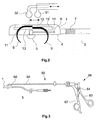
- Figures 1 and 2 show a schematic representation of a bipolar epicardial electrode for a cardiac stimulation device as a first embodiment for the epicardial electrode according to the invention.
- Fig. 1 shows the electrode in supervision, while Fig. 2 shows the electrode in a vertical section.
- the electrode comprises an electrode body 1, for example made of silicone, which is arranged at the distal end of an electrode line 3 and the underside of which Forms stimulation surface 4 of the epicardial electrode with a different pole 5.
- the stimulation signals to the heart.
- the Different pole 5 via an electrical line running through the electrode line 3 6 connected to the stimulation device.
- the indifferent pole 7 is in the embodiment shown as an annular electrode surface on the electrode line 3 arranged.
- the electrode shown in FIGS. 1 and 2 is a bipolar electrode formed, but it can also be designed as a unipolar electrode. In this In this case, there is no indifferent pole 7 on the electrode line. Instead serves then z. B. the housing of the stimulation device or a patch electrode as indifferent pole.
- the epicardial electrode according to the invention comprises four claws 9 as fixing elements (two of which can be seen in Fig. 2), which are opposite one another in pairs are arranged in channels 11 of the electrode body 1.
- the claws 9 can be move along these channels 11 between two end positions, the claws in the one end position, which is shown in Fig. 2, from the electrode body are extended so that their claw tips protrude beyond the stimulation surface 4.
- Eyes 13 are arranged at the end of the claws 9 opposite the claw tips, the sections of the channels running parallel to the stimulation surface are located and the engagement of balls 51, 52 of an introducer 50, which as Actuating elements for actuating the claws allow. Every pair of claws a common eyelet is assigned.
- the claws 9 By moving the balls 51, 52 against one another parallel to the stimulation surface 4 the claws 9 can be retracted and extended. In particular, they can be made from one State in which they are completely within the channels 11, in the extended Bring condition. The condition in which the claws are completely inside the Channels are arranged is by the corresponding end position shown in dashed lines the eyelets 13 'indicated. If the stimulation surface 4 on the heart muscle is present, the claws 9 penetrate into the heart tissue as they extend and anchor them in this way the electrode.
- an additional fixation of the epicardium electrode on the Heart tissue allows is a medical on the underside of the stimulation surface 4 Dacron fabric 14 arranged (not shown in Fig. 2), the one Allows the electrode to adhere to the heart tissue.
- pole 5 is equipped with a steroid reservoir his. The steroid is used to reduce inflammation that occurs when the claws are inserted inhibit the heart tissue.
- the electrode does include fixing elements four claws 9, which lie opposite one another in pairs in the electrode body 1 are arranged, however, any number of fixing elements can be used come.
- the number of fixing elements can, for example, depend on the size the stimulation area or the degree of fixation desired.
- FIG. 3 shows schematically an embodiment for the introducer 50 for Introducing the epicardial electrode according to the invention into the body.
- the Introducer 50 includes a hollow tube 54, one at its distal end Engagement in the eyelets 13 of the claws 9 configured ball 51 is fixed.
- a rod 56 which is in relation to the hollow tube 54 in Can be moved longitudinally.
- a second one designed to engage in the eyelets 13 of the claws 52.
- a handle 58 with two handle parts 60, 62 arranged.
- the two handle parts 60, 62 can be pivoted in this way via a joint 64 arranged to each other and connected to the rod 56 or the tube 54 that itself the balls 51, 52 move towards each other when the two handle parts 60, 62 towards each other to be pivoted, and the two balls 51, 52 away from each other move when the two handle parts 60, 62 are pivoted away from each other.
- the Balls 51, 52, tube 54, rod 56 and handle 58 together form one Actuating mechanism for retracting and extending the claws 9.
- the introducer 50 also serves for placement the electrode, which, for example, by means of the balls 51, 52 on the insertion device 50 is held. Once the electrode is placed in the right place on the heart, it can be attached using the operating mechanism. After this Extending the claws 9, the introducer 50 is removed again.
- the top of the Electrode body 1 two extending in the direction of displacement of the eyelets 13 Have slots or elongated holes, where the eyes 13 in the extended State of the claws 9 are so widened that the balls 51, 52 only on this point, i.e. when the claws are extended, through the slots or Slots can pass through.
- the Balls 51, 52 are inserted into the eyelets 13 when the claws are extended, and then the claws are retracted by actuating the actuating mechanism. there the balls 51, 52 get into those sections of the slots or elongated holes that do not allow balls 51, 52 to pass through. Only after extending the The balls 51, 52 can be clawed, i.e. after the electrode has been fixed pull out of the eyelets 13.
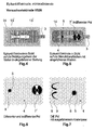
- FIGs 4 to 7 show a second embodiment of the invention Epicardium electrode
- FIG. 4 a view of the electrode body 1
- FIG. 5 show a view of the stimulation surface 4.
- Figure 6 shows an enlarged Representation of a section of the stimulation surface 4, the different and includes indifferent pole 5 or 7 'of the epicardial electrode. 7 is the stimulation area 4 in one showing the different pole 5 and the extended claws 9 shown enlarged view.
- Features of the second embodiment, the do not differ from those of the first embodiment, are with the same reference numerals as in the first embodiment.
- the second embodiment differs from the first only in that the indifferent pole 7 ′ does not form an annular electrode surface on the electrode line 3 is arranged, but just like the different pole 5 on the stimulation surface 4. This allows good contact between the indifferent pole 7 'and the Achieve heart tissue.
- arranging the indifferent increases Electrode 7 'on the stimulation surface 4 because of the distance between the indifferent and the different pole can be approximately 10 mm or more.
- the electrode body 1 is approximately 4.6 mm high, approximately 10 mm wide and approx. 25 mm long.
- the area of the arranged on the stimulation area Dacron fabric is approx. 14 mm x 32 mm.
- the claws 9 can be made of wire, for example, and typically have a diameter of about 0.2 mm.
- the channels for the claws 9 in the electrode body 1 then typically have a diameter of approximately 0.4 mm.
- the differente and the indifferent pole typically have a diameter of approx. 1.8 mm or 4.0 mm, the thickness of the different pole approximately 0.6 mm and that of the indifferent pole is approximately 0.3 mm.
- a steroid reservoir is located in the center of the different pole 8 with a diameter of approx. 1.0 mm, which contains approx. 1 mg of a steroid, e.g. Dexamethasone phosphate.
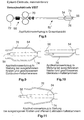
- Figure 8 shows a second embodiment of the invention Introducer.
- the introducer 50 'according to the second embodiment corresponds in principle to that of the first embodiment.
- Features of the introducer according to the second embodiment, which differ from do not differ from those of the first embodiment are in both embodiments with the same reference numerals.
- the second embodiment includes the handle 68 of the actuator to each other Move the balls not two swiveling handle parts but instead two mutually displaceable handle parts 70, 72.
- the introducer also includes 50 'of the second exemplary embodiment, two holding clips 74, 76 for holding the electrode during the insertion and fixing process.
- the retaining clips 74, 76 can optionally in a device provided on the handle 68 in a closed position, in which they have an electrode at the distal end of the introducer hold, or in an open position in which the electrode is not held become.
- Figures 9 and 10 show the distal end of the introducer 50 'in the Configuration that it with extended claws of the electrode and with closed Holding clips 74, 75 has.
- Figure 11 shows the distal end of the introducer however, with the claws retracted and the holding clips 74, 76 open.
- the introducer 50 ' is in accordance with the second exemplary embodiment with closed retaining clips 74, 76 and from retaining clips 74, 76 epicardial electrode shown.
- To hold the epicardial electrode securely to be supported by the retaining clips 74, 76 are in the side walls of the Electrode body 1 grooves 16 into which the retaining clips 74, 76 in intervene closed state.
- 12 to 14 the electrode and the distal end of the introducer 50 'from different angles extended claws 9 and closed retaining clips 74, 76 show the FIGS. 15 and 16 show the electrode and the distal end of the insertion set 50 ' retracted claws 9 and closed retaining clips 74, 76.
- the actuators instead of as balls simple pins suitable for engaging in the eyelets 13 of the claws 9 of the electrode to train because the actuators do not have a holding function for the electrode need.
Abstract
Description
Die vorliegende Erfindung betrifft eine Epikard-Elektrode, also eine an der Außenseite des Herzmuskels anzubringende Elektrode, für ein Herzstimulationsgerät, wie etwa einen Defibrillator oder einen Herzschrittmacher.The present invention relates to an epicardial electrode, that is to say one on the outside of the heart muscle to be attached, for a cardiac stimulation device such as a defibrillator or a pacemaker.
Das Zuführen elektrischer Signale als Stimulationssignale, um bspw. den Herzrhythmus wieder herzustellen oder den Rhythmus des Herzschlages stabil zu halten, ist eine seit langem angewandte medizinische Therapie. Hiezu werden Herzschrittmacher, aber auch implantierbare Defibrillatoren in den Brustkorb eines Patienten eingesetzt, die mittels einer internen Energiequelle, bspw. einer Batterie, bei Bedarf die elektrischen Signale erzeugen. Diese werden dann über eine Elektrodenleitung, an deren dem Herzschrittmacher abgewandten Ende (man spricht in diesem Zusammenhang auch vom distalen Ende der Elektrodenleitung) eine Elektrode angeordnet ist, einer bestimmten, von der medizinischen Anwendung abhängigen Stelle des Herzens zugeführt.The supply of electrical signals as stimulation signals, for example the heart rhythm restore or keep the rhythm of the heartbeat stable, is a long-used medical therapy. For this, pacemakers but also implantable defibrillators in a patient's chest used by means of an internal energy source, for example a battery, if necessary generate electrical signals. These are then connected to an electrode line the end facing away from the pacemaker (one speaks in this context an electrode is also arranged from the distal end of the electrode line), a specific part of the heart, depending on the medical application fed.
Die Elektrode kann je nach Therapiezweck eine unipolare Elektrode oder eine bipolare Elektrode sein. Unter einer unipolaren Elektrode versteht man eine Elektrode mit einem einzigen Pol, dem sog. differenten Pol, der die Stimulationspulse aussendet. Der unipolaren Elektrode ist eine Referenzelektrode mit sog. indifferentem Pol zugeordnet. Die Referenzelektrode, die auch als indifferente Elektrode bezeichnet wird, wird häufig von einer an der Außenhaut des Herzmuskels (Epikard) angeordneten Patch-Elektrode oder vom Gehäuse des Stimulationsgerätes gebildet. An der Außenseite des Herzmuskels angebrachte Elektroden werden auch Epikard-Elektroden oder epikardiale Elektroden genannt.Depending on the therapeutic purpose, the electrode can be a unipolar electrode or a bipolar one Electrode. A unipolar electrode is an electrode with a single pole, the so-called different pole, which emits the stimulation pulses. The unipolar Electrode is assigned a reference electrode with a so-called indifferent pole. The Reference electrode, which is also referred to as an indifferent electrode, is often used by a patch electrode arranged on the outer skin of the heart muscle (epicardium) or formed by the housing of the stimulation device. On the outside of the heart muscle attached electrodes also become epicardial or epicardial electrodes Called electrodes.
Eine bipolare Elektrode weist im Gegensatz zur unipolaren Elektrode sowohl einen differenten als auch einen indifferenten Pol auf, so dass keine weitere Elektrode benötigt wird.In contrast to the unipolar electrode, a bipolar electrode has both differen as well as an indifferent pole, so that no further electrode is needed.
Zur Stimulation des Apex, also der Herzspitze, die bspw. zum Stabilisieren des Herzrhythmus erfolgt, wird im Stand der Technik eine Elektrode im Inneren des Herzens im Bereich des Apex fixiert. Dabei ist ein Durchführen der Elektrodenleitung durch die Herzkammern bzw. durch den Sinus Coronarius nötig. Eine in der Nähe des Apex der rechten Herzkammer platzierte Elektrode ist bspw. in US 5,683,447 gezeigt. Das Platzieren der Elektrode durch die Herzkammern oder den Sinus Coronarius ist jedoch nicht ungefährlich.To stimulate the apex, i.e. the tip of the heart, for example to stabilize the Heart rhythm occurs, in the prior art, an electrode inside the Heart fixed in the area of the apex. There is a passage of the electrode lead through the ventricles or through the coronary sinus. One near the The apex of the right ventricle is shown, for example, in US Pat. No. 5,683,447. Placement of the electrode is through the ventricles or the coronary sinus however not harmless.
Es ist daher eine Aufgabe der Erfindung, eine Elektrode zur Verfügung zu stellen, die das Risiko für den Patienten beim Platzieren der Elektrode vermindert.It is therefore an object of the invention to provide an electrode which reduces the risk for the patient when placing the electrode.
Es ist eine weitere Aufgabe der Erfindung, ein geeignetes Einführbesteck zum Einführen der erfindungsgemäßen Elektrode in den Körper zur Verfügung zu stellen.It is a further object of the invention to provide a suitable introducer for To provide insertion of the electrode according to the invention into the body.
Die erste Aufgabe wird durch eine Epikard-Elektrode nach Anspruch 1 gelöst, die
zweite Aufgabe durch ein Einführbesteck nach Anspruch 13. Die abhängigen
Ansprüche definieren vorteilhafte Ausgestaltungen der Epikard-Elektrode bzw. des
Einführbestecks.The first object is achieved by an epicardium electrode according to claim 1
second task through an introducer according to
Eine erfindungsgemäße Epikard-Elektrode, die sich insbesondere zur Verwendung mit einem Herzstimulationsgerät eignet, umfasst einen Elektrodenkörper, der eine zur Anlage an das Herzgewebe und zur Stimulation einer Partie des Herzens, d. h. eines Teilbereiches des Herzens, ausgebildete Stimulationsfläche und mindestens ein Fixierelement zum Fixieren der Stimulationsfläche am Herzgewebe aufweist. Das mindestens eine Fixierelement ist zum Eingriff in das Herzgewebe ausgestaltet. An epicardial electrode according to the invention, which is particularly suitable for use with a cardiac stimulation device is suitable, comprises an electrode body, one for Attachment to the heart tissue and to stimulate a part of the heart, d. H. one Partial area of the heart, trained stimulation area and at least one Has fixing element for fixing the stimulation surface on the heart tissue. The at least one fixing element is designed to engage in the heart tissue.
Die erfindungsgemäße Epikard-Elektrode kann an der Außenseite und insbesondere an der Außenhaut des Herzmuskels (Epikard) befestigt werden, ohne wie eine Patch-Elektrode mit dem Herzmuskel vernäht zu werden. Es muss lediglich das Fixierelement in Eingriff mit dem Herzgewebe gebracht werden. Die erfindungsgemäße Elektrode erleichtert den Zugang zum Herzen und ermöglicht es insbesondere, die Elektrode in einem minimalinvasiven Eingriff anzubringen.The epicardial electrode according to the invention can be on the outside and in particular to be attached to the outer skin of the heart muscle (epicardium) without like a patch electrode to be sutured to the heart muscle. It only needs the fixing element be brought into engagement with the heart tissue. The electrode according to the invention facilitates access to the heart and, in particular, allows the electrode in a minimally invasive procedure.
Darüber hinaus ermöglicht die Ausgestaltung der Stimulationsfläche derart, dass im Gegensatz zu einer Patch-Elektrode nur eine Partie, also ein Teilbereich des Herzens stimuliert wird, die gezielte Stimulation bestimmter Herzbereiche. So kann die erfindungsgemäße Elektrode dazu genutzt werden, bspw. den Apex des Herzens von der Außenseite des Herzens aus zu stimulieren. Ein Platzieren der Elektrode durch die Herzkammern oder den Sinus Coronarius braucht in diesem Fall nicht zu erfolgen.In addition, the design of the stimulation surface such that in the In contrast to a patch electrode, only one part, i.e. a part of the heart is stimulated, the targeted stimulation of certain areas of the heart. So it can Electrode according to the invention can be used, for example. The apex of the heart of stimulate from the outside of the heart. Placing the electrode through the Ventricles or the coronary sinus need not be done in this case.
Die Möglichkeit, den Apex durch Platzieren der erfindungsgemäßen Elektrode zu stimulieren, ohne dass die Elektrodenleitung durch die Herzkammern oder den Sinus Coronalis geführt zu werden braucht, verringert im Vergleich zum Stand der Technik das Risiko, dem der Patient beim Platzieren der Elektrode ausgesetzt ist.The possibility of closing the apex by placing the electrode according to the invention stimulate without the electrode lead through the heart chambers or the sinus Coronalis needs to be guided, reduced compared to the prior art the risk the patient is exposed to when placing the electrode.
Die erfindungsgemäße Elektrode erleichtert insgesamt also den insbesondere für die Stimulation des Herzrhythmus und/oder zum Abfühlen von Herzsignalen bedeutenden Zugang zum Apex des linken Herzens.Overall, the electrode according to the invention therefore facilitates this in particular for Significant stimulation of the heart rhythm and / or for sensing heart signals Access to the left heart apex.
Das mindestens eine Fixierelement kann, um das Fixieren der Stimulationsfläche ohne Vernähen zu ermöglichen, insbesondere in Form einer in das Herzgewebe einbringbaren Kralle ausgestaltet sein.The at least one fixing element can be used to fix the stimulation surface without To enable suturing, in particular in the form of an insertable into the heart tissue Claw be designed.
In einer vorteilhaften Weiterbildung ist die Kralle derart beweglich ausgestaltet, dass sie zum Fixieren des Elektrodenkörpers am Herzgewebe aus einem in den Elektrodenköper eingezogenen Zustand zum Herstellen des Eingriffs mit dem Herzgewebe auszufahren ist. Die Kralle kann dann während des Einführens der Elektrode in den Körper in den Elektrodenkörper eingezogen sein, um das Einführen nicht zu behindern. Erst dann, wenn die Elektrode ihre Zielposition im Körper erreicht hat, wird die Kralle ausgefahren um die Stimulationsfläche zu fixieren. Besonders vorteilhaft ist diese Ausgestaltung, wenn die Kralle in der in den Elektrodenkörper eingezogenen Position vollständig im Inneren des Elektrodenkörpers angeordnet ist. In an advantageous development, the claw is designed so that it can move for fixing the electrode body to the heart tissue from one into the electrode body retracted condition for engaging the heart tissue is to be extended. The claw can then be inserted into the electrode during insertion Be drawn into the body of the electrode so as not to impede the insertion. Only when the electrode has reached its target position in the body does the claw become extended to fix the stimulation surface. This is particularly advantageous Design when the claw in the retracted position in the electrode body is completely arranged inside the electrode body.
In einer weiteren Ausgestaltung der erfindungsgemäßen Elektrode umfasst der Elektrodenkörper zur Aufnahme der Kralle einen Kanal mit einem langgestreckten, zur Stimulationsfläche parallel verlaufenden Kanalabschnitt und einem derart gekrümmten Kanalabschnitt, dass der Kanal eine Austrittsöffnung in der Stimulationsfläche aufweist. Außerdem ist mindestens ein Teil der Kralle derart flexibel ausgebildet und im Kanal angeordnet, dass er sich im eingezogenen Zustand der Kralle im Wesentlichen langgestreckt im langgestreckten Kanalabschnitt und im ausgefahrenen Zustand im gekrümmten Kanalabschnitt befindet. Beim Ausfahren der Kralle tritt der flexible Teil der Kralle aus dem langgestreckten Kanalabschnitt in den gekrümmten Kanalabschnitt ein. In dieser Ausgestaltung verläut mindestens ein Teil der Kralle im eingezogenen Zustand parallel zur Stimulationsfläche. Der parallele Verlauf des Krallenteils im eingezogenen Zustand ermöglicht es, die Kralle vollständig in den Elektrodenkörper einzuziehen und gleichzeitig die Bauhöhe des Elektrodenkörpers relativ flach zu halten. Dies ist insbesondere von Bedeutung, wenn die Abmessungen der Elektrode gering gehalten werden sollen, um das Implantieren in einem minimalinvasiven Eingriff zu erleichtern.In a further embodiment of the electrode according to the invention, the Electrode body for receiving the claw a channel with an elongated, for Stimulation surface parallel channel section and such a curved Channel section that the channel has an outlet opening in the stimulation surface. In addition, at least part of the claw is designed to be flexible and in the channel arranged that it is essentially in the retracted state of the claw elongated in the elongated channel section and in the extended state in the curved Channel section is located. When the claw is extended, the flexible part of the Claw from the elongated channel section into the curved channel section. In this embodiment, at least a part of the claw mounts in the retracted position State parallel to the stimulation surface. The parallel course of the claw part in the retracted Condition allows the claw to be fully drawn into the electrode body and at the same time to keep the height of the electrode body relatively flat. This is particularly important if the dimensions of the electrode are small should be kept to implant in a minimally invasive procedure facilitate.
Die Kralle kann insbesondere auch einen zum Eingriff in das Herzgewebe vorgesehenen steifen Krallenabschnitt aufweisen, der bogenförmig ausgebildet ist und der sich im eingezogenen Zustand im gekrümmten Kanalabschnitt befindet. Die Steife des gekrümmten Krallenabschnittes wirkt einem Verbiegen der Kralle beim Herstellen des Eingriffs mit dem Herzgewebe entgegen.The claw can in particular also be used to intervene in the heart tissue provided stiff claw portion which is arcuate and which is in the retracted state in the curved channel section. The stiffness the curved claw section acts to bend the claw during manufacture against the intervention with the heart tissue.
Um eine besonders sichere Befestigung der Stimulationsfläche am Herzgewebe zu gewährleisten, umfasst die erfindungsgemäße Elektrode vorteilhafterweise mehrere Krallen. Insbesondere können zwei einander gegenüberliegende Krallenpaare vorhanden sein.To secure the stimulation surface to the heart tissue in a particularly secure manner ensure, the electrode according to the invention advantageously comprises several Claws. In particular, two mutually opposite claw pairs can be present his.
Um das Implantieren in einem minimalinvasiven Eingriff zu vereinfachen, ist in einer vorteilhaften Ausgestaltung der erfindungsgemäßen Elektrode jedem Fixierelement ein Eingriffselement zugeordnet, das einen lösbaren Eingriff eines zum Betätigen des Fixierelementes ausgestalteten Betätigungselementes ermöglicht. Insbesondere kann ein Eingriffselement, bspw. eine Öse, gleichzeitig mehreren Fixierelementen, d. h. bspw. mehreren Krallen, zugeordnet sein. Alternativ kann jedes Fixierelement jedoch auch sein eignes Eingriffselement besitzen. Die Elektrode kann dann mit dem Betätigungselement im Eingriff in das Eingriffselement am Herzen positioniert werden. Anschließend wird das Fixierelement mit Hilfe des Betätigungselementes in Eingriff mit dem Herzgewebe gebracht. Nachdem der Eingriff mit dem Herzgewebe hergestellt ist, wird er Eingriff des Betätigungselementes in das Eingriffselement gelöst. Das Betätigungselement kann dann entfernt werden.To simplify implantation in a minimally invasive procedure, one is advantageous embodiment of the electrode according to the invention each fixing element Engagement element associated with a releasable engagement of one for actuating the Fixing element designed actuating element allows. In particular, can an engagement element, for example an eyelet, simultaneously a plurality of fixing elements, d. H. For example, several claws can be assigned. Alternatively, however, each fixing element also have its own engaging element. The electrode can then with the Actuating element can be positioned in engagement in the engagement element on the heart. The fixing element is then engaged with the aid of the actuating element brought to the heart tissue. After the heart tissue procedure is established, the engagement of the actuating element in the engagement element is released. The The actuator can then be removed.
In einer Weiterbildung dieser Ausgestaltung ermöglicht das Eingriffselement das Ausfahren einer Kralle durch im Wesentlichen paralleles Verschieben des Betätigungselementes relativ zur Stimulationsfläche, insbesondere dann, wenn der Elektrodenkörper einen langgestreckten Kanalabschnitt zur Aufnahme der Kralle aufweist.In a further development of this embodiment, the engagement element enables this Extending a claw by moving the actuating element essentially parallel relative to the stimulation area, especially if the Electrode body an elongated channel section for receiving the claw having.
In einer weiteren Ausgestaltung der Epikard-Elektrode weist diese an der Stimulationsfläche einen differenten Pol auf. Der differente Pol kann mit einem Reservoir eines entzündungshemmenden Wirkstoffes, bspw. eines Steroids, ausgestattet sein, um das Entstehen von Entzündungen durch das Eingreifen des Fixierelementes in das Herzgewebe zu hemmen. Mittels des differenten Pols können der zu stimulierenden Partie des Herzens die geeigneten Stimulationssignale zugeführt werden. Außerdem ermöglicht der differente Pol auch das Abfühlen elektrischer Signale des Herzens, die bspw. zum Auslösen oder Triggern der Stimulation herangezogen werden können.In a further embodiment of the epicardial electrode, this has on the stimulation surface a different pole. The different pole can be connected to a reservoir anti-inflammatory agent, such as a steroid, to be equipped Inflammation arises from the intervention of the fixation element in the heart tissue to inhibit. The part to be stimulated can be stimulated by means of the different pole the appropriate stimulation signals are supplied to the heart. Moreover The different pole also enables the heart to sense electrical signals For example, can be used to trigger or trigger the stimulation.
Zusätzlich zu dem Fixierelement kann die Stimulationsfläche noch ein medizinisches Gewebe, bspw. Dacron, zum Festwachsen mit dem Herzgewebe umfassen. Dies ermöglicht ein besonders sicheres Fixieren der Stimulationsfläche am Herzgewebe.In addition to the fixing element, the stimulation surface can also be a medical one Tissue, such as Dacron, to adhere to the heart tissue. This enables a particularly secure fixation of the stimulation surface to the heart tissue.
Erfindungsgemäß wird auch ein Einführbesteck zum minimalinvasiven Einführen einer erfindungsgemäßen Elektrode in den Körper zur Verfügung gestellt, das einen Betätigungsmechanismus mit einem Betätigungselement zum Betätigen des mindestens einen Fixierelementes derart, dass der Eingriff des Fixierelementes mit dem Herzgewebe hergestellt wird, aufweist. Das Einführbesteck stellt damit ein Applikationswerkzeug dar, das außer zum Platzieren der Elektrode auch zum Herstellen des Eingriffs verwendet werden kann. Der Betätigungsmechanismus kann insbesondere derart ausgestaltet sein, dass er ein Ausfahren mindestens einer Kralle aus dem Elektrodenkörper ermöglicht. According to the invention, an introducer is also used for minimally invasive insertion provided electrode in the body, the one Actuating mechanism with an actuating element for actuating the at least one fixing element such that the engagement of the fixing element with the heart tissue is produced. The introducer sets with it Application tool that, in addition to placing the electrode, also for Making the procedure can be used. The operating mechanism can in particular be designed such that it extends at least one claw from the electrode body.
Zur Verwendung für implantierbaren Elektroden, bei denen als Fixierelement eine flexible Kralle Verwendung findet, die sich im eingezogenen Zustand zumindest teilweise in einem zur Stimulationsfläche parallel verlaufenden Kanalabschnitt befindet, ist der Betätigungsmechanismus in einer Ausgestaltung des Einführbestecks derart ausgebildet, dass er ein im Wesentlichen paralleles Verschieben des Betätigungselementes relativ zur Stimulationsfläche ermöglicht. Das Verschieben des Betätigungselementes führt dann zu einem ebenfalls relativ zur Stimulationsfläche parallelen Verschieben des mit der Kralle verbundenen Eingriffselementes, was wiederum zu einem Ausfahren der Kralle aus dem Elektrodenkörper führt.For use with implantable electrodes in which a flexible claw is used, which is at least partially in the retracted state is located in a channel section running parallel to the stimulation surface the actuation mechanism in one embodiment of the introducer formed that he a substantially parallel displacement of the actuating element relative to the stimulation area. Moving the actuator then leads to a parallel also relative to the stimulation surface Moving the engaging element connected to the claw, which in turn increases extending the claw out of the electrode body.
Um ein sicheres Halten der Elektrode während des Positionierens zu ermöglichen, kann das Einführbesteck außerdem mit Halteklammern zum Halten der implantierbaren Elektrode beim Einführen der implantierbaren Elektrode in den Körper ausgestattet sein.To allow the electrode to be held securely during positioning, the introducer can also be used with holding clips to hold the implantable Electrode when inserting the implantable electrode into the body his.
Weitere Merkmale, Eigenschaften und Vorteile der Erfindung ergeben sich aus der nachfolgenden Beschreibung von Ausführungsbeispielen unter Bezugnahme auf die beiliegenden Figuren.
Figur 1- zeigt in Aufsicht schematisch ein erstes Ausführungsbeispiel für die erfindungsgemäße Epikard-Elektrode.
- Figur 2
- zeigt schematisch das erste Ausführungsbeispiel für die erfindungsgemäße Epikard-Elektrode in einem vertikalen Schnitt.
Figur 3- zeigt schematisch ein erstes Ausführungsbeispiel für das Einführbesteck zum Einführen der erfindungsgemäßen Epikard-Elektrode.
Figur 4- zeigt die Oberseite eines zweiten Ausführungsbeispiels für die erfindungsgemäße Epikard-Elektrode.
Figur 5- zeigt die Unterseite des zweiten Ausführungsbeispiels für die erfindungsgemäße Epikard-Elektrode.
- Figuren 6 u. 7
- zeigen Details der Unterseite des zweiten Ausführungsbeispiels für die erfindungsgemäße Epikard-Elektrode.
Figur 8- zeigt in einer Gesamtansicht ein zweites Ausführungsbeispiel für das Einführbesteck für die erfindungsgemäße Epikard-Elektrode.
- Figuren 9 - 11
- zeigen das zweite Ausführungsbeispiel für das erfindungsgemäße Einführbesteck in verschiedenen Stellungen.
- Figuren 12 - 16
- zeigen das zweite Ausführungsbeispiel für das erfindungsgemäße Einführbesteck mit daran angeordneter Epikard-Elektrode in verschiedenen Stellungen.
- Figure 1
- shows a top view schematically shows a first embodiment of the epicardium electrode according to the invention.
- Figure 2
- shows schematically the first embodiment of the epicardium electrode according to the invention in a vertical section.
- Figure 3
- shows schematically a first embodiment of the introducer for inserting the epicardium electrode according to the invention.
- Figure 4
- shows the top of a second embodiment for the epicardium electrode according to the invention.
- Figure 5
- shows the underside of the second embodiment for the epicardium electrode according to the invention.
- Figures 6 u. 7
- show details of the underside of the second embodiment for the epicardium electrode according to the invention.
- Figure 8
- shows an overall view of a second embodiment of the introducer for the epicardium electrode according to the invention.
- Figures 9-11
- show the second embodiment of the introducer according to the invention in different positions.
- Figures 12-16
- show the second embodiment of the introducer according to the invention with an epicardial electrode arranged thereon in different positions.
Die Figuren 1 und 2 zeigen in einer schematischen Darstellung eine bipolare Epikard-Elektrode für ein Herzstimulationsgerät als ein erstes Ausführungsbeispiel für die erfindungsgemäße Epikard-Elektrode. Fig. 1 zeigt die Elektrode in Aufsicht, während Fig. 2 die Elektrode in einem vertikalen Schnitt zeigt.Figures 1 and 2 show a schematic representation of a bipolar epicardial electrode for a cardiac stimulation device as a first embodiment for the epicardial electrode according to the invention. Fig. 1 shows the electrode in supervision, while Fig. 2 shows the electrode in a vertical section.
Die Elektrode umfasst einen bspw. aus Silikon bestehenden Elektrodenkörper 1, der
am distalen Ende einer Elektrodenleitung 3 angeordnet ist und dessen Unterseite die
Stimulationsfläche 4 der Epikard-Elektrode mit einem differenten Pol 5 bildet. Über den
differenten Pol 5 werden beim Stimulationsbetrieb des Stimulationsgeräts (nicht
dargestellt) die Stimulationssignale an das Herz abgegeben. Zu diesem Zweck ist der
differente Pol 5 über eine durch die Elektrodenleitung 3 verlaufende elektrische Leitung
6 mit dem Stimulationsgerät verbunden. Der indifferente Pol 7 ist im gezeigten Ausführungsbeispiel
als ringförmige Elektrodenfläche an der Elektrodenleitung 3
angeordnet.The electrode comprises an
Zwar ist die in den Figuren 1 und 2 dargestellte Elektrode als bipolare Elektrode
ausgebildet, sie kann jedoch auch als unipolare Elektrode ausgebildet sein. In diesem
Fall ist kein indifferenter Pol 7 an der Elektrodenleitung vorhanden. Stattdessen dient
dann z. B. das Gehäuse des Stimulationsgerätes oder eine Patch-Elektrode als
indifferenter Pol.The electrode shown in FIGS. 1 and 2 is a bipolar electrode
formed, but it can also be designed as a unipolar electrode. In this
In this case, there is no
Als Fixierelemente umfasst die erfindungsgemäße Epikard-Elektrode vier Krallen 9
(von denen in Fig. 2 zwei zu erkennen sind), die einander gegenüberliegend paarweise
in Kanälen 11 des Elektrodenkörpers 1 angeordnet sind. Die Krallen 9 lassen sich
entlang dieser Kanäle 11 zwischen zwei Endstellungen verschieben, wobei die Krallen
in der einen Endstellung, die in Fig. 2 dargestellt ist, aus dem Elektrodenkörper
ausgefahren sind, so dass ihre Krallenspitzen über die Stimulationsfläche 4 vorstehen.
Am den Krallenspitzen entgegengesetzten Ende der Krallen 9 sind Ösen 13 angeordnet,
die sich in parallel zur Stimulationsfläche verlaufenden Abschnitten der Kanäle
befinden und den Eingriff von Kugeln 51, 52 eines Einführbestecks 50, die als
Betätigungselemente zum Betätigen der Krallen dienen, ermöglichen. Jedem Krallenpaar
ist dabei eine gemeinsame Öse zugeordnet.The epicardial electrode according to the invention comprises four
Durch gegeneinander Verschieben der Kugeln 51, 52 parallel zur Stimulationsfläche 4
lassen sich die Krallen 9 ein- und ausfahren. Insbesondere lassen sie sich aus einem
Zustand, in dem sie sich vollständig innerhalb der Kanäle 11 befinden, in den ausgefahrenen
Zustand bringen. Der Zustand, in dem die Krallen vollständig im Inneren der
Kanäle angeordnet sind, ist durch die entsprechende, gestrichelt dargestellte Endposition
der Ösen 13' angedeutet. Wenn die Stimulationsfläche 4 am Herzmuskel
anliegt, dringen die Krallen 9 beim Ausfahren in das Herzgewebe ein und verankern so
die Elektrode.By moving the
Als optionale Ausstattung, die eine zusätzliche Fixierung des Epikard-Elektrode am
Herzgewebe ermöglicht, ist an der Unterseite der Stimulationsfläche 4 ein medizinisches
Dacron-Gewebe 14 angeordnet (in Fig. 2 nicht dargestellt), das ein
Festwachsen der Elektrode am Herzgewebe ermöglicht. Außerdem kann der differente
Pol 5 in einer weiteren optionalen Ausgestaltung mit einem Steroid-Reservoir ausgestattet
sein. Das Steroid dient dazu, Entzündungen, die beim Einbringen der Krallen in
das Herzgewebe entstehen können, zu hemmen.As an optional extra, an additional fixation of the epicardium electrode on the
Heart tissue allows is a medical on the underside of the
Zwar umfasst die Elektrode im beschriebenen Ausführungsbeispiel als Fixierelemente
vier Krallen 9, die einander gegenüberliegend paarweise im Elektrodenkörper 1
angeordnet sind, jedoch kann jede beliebige Anzahl Fixierelemente zur Anwendung
kommen. Die Zahl der Fixierelemente kann dabei bspw. in Abhängigkeit von der Größe
der Stimulationsfläche oder vom Grad der gewünschten Fixierung gewählt werden.In the exemplary embodiment described, the electrode does include fixing elements
four
Figur 3 zeigt schematisch ein Ausführungsbeispiel für das Einführbesteck 50 zum
Einführen der erfindungsgemäßen Epikard-Elektrode in den Körper. Eine vergrößerte
Darstellung des distalen Endes des Einführbestecks ist in Fig. 2 zu erkennen. Das
Einführbesteck 50 umfasst eine hohle Röhre 54, an deren distalem Ende eine zum
Eingriff in die Ösen 13 der Krallen 9 ausgestaltete Kugel 51 fixiert ist. Im Inneren der
hohlen Röhre 54 ist eine Stange 56 angeordnet, die sich relativ zur hohlen Röhre 54 in
Längsrichtung verschieben lässt. Am Ende der Stange 56 befindet sich eine zweite
zum Eingriff in die Ösen 13 der Krallen ausgestaltete Kugel 52. Durch Verschieben der
Stange 56 gegen die Röhre 54 lassen sich die Kugeln 51 und 52 voneinander weg und
aufeinander zu bewegen. Sind die Kugeln 51, 52 dabei in die Ösen 13 der Krallen 9
eingeloggt, so führt das Bewegen der Kugeln 51, 52 aufeinander zu zu einem
Ausfahren der Krallen 9 aus den Kanälen 11 und das Bewegen der Kugeln 51, 52
voneinander weg zu einem Einziehen der Krallen 9 in die Kanäle 11.Figure 3 shows schematically an embodiment for the
Am proximalen Ende des Einführbestecks 50 ist ein Griff 58 mit zwei Griffteilen 60, 62
angeordnet. Die beiden Griffteile 60, 62 sind über ein Gelenk 64 derart schwenkbar
zueinander angeordnet und mit der Stange 56 bzw. der Röhre 54 verbunden, dass sich
die Kugeln 51, 52 aufeinander zu bewegen, wenn die beiden Griffteile 60, 62 aufeinander
zu verschwenkt werden, und sich die beiden Kugeln 51, 52 voneinander weg
bewegen, wenn die beiden Griffteile 60, 62 voneinander weg verschwenkt werden. Die
Kugeln 51, 52, die Röhre 54, die Stange 56 sowie der Griff 58 bilden zusammen einen
Betätigungsmechanismus zum Ein- und Ausfahren der Krallen 9.At the proximal end of the
Außer zum Betätigen der Krallen 9 dient das Einführbesteck 50 auch zum Platzieren
der Elektrode, die dabei bspw. mittels der Kugeln 51, 52 am Einführbesteck 50
gehalten wird. Sobald die Elektrode an der richtigen Stelle des Herzens platziert ist,
kann sie mit Hilfe des Betätigungsmechanismus befestigt werden. Nach dem
Ausfahren der Krallen 9 wird das Einführbesteck 50 wieder entfernt.In addition to actuating the
Um das Halten der Elektrode beim Platzieren und das Entfernen des Einführbestecks
50 nach dem Fixieren der Elektrode zu ermöglichen, kann die Oberseite des
Elektrodenkörpers 1 zwei sich in Verschieberichtung der Ösen 13 erstreckende
Schlitze oder Langlöcher aufweisen, die dort, wo sich die Ösen 13 im ausgefahrenen
Zustand der Krallen 9 befinden, derart verbreitert sind, dass die Kugeln 51, 52 nur an
dieser Stelle, also im ausgefahrenen Zustand der Krallen, durch die Schlitze bzw.
Langlöcher hindurchtreten können. Vor dem Einsetzen der Elektrode werden die
Kugeln 51, 52 bei ausgefahrenen Krallen in die Ösen 13 eingeführt, und anschließend
werden die Krallen durch Betätigen des Betätigungsmechanismus eingezogen. Dabei
gelangen die Kugeln 51, 52 in diejenigen Abschnitte der Schlitze bzw. Langlöcher, die
einen Durchtritt der Kugeln 51, 52 nicht erlauben. Erst nach dem Ausfahren der
Krallen, also nach dem erfolgten Fixieren der Elektrode, lassen sich die Kugeln 51, 52
aus den Ösen 13 herausziehen.To hold the electrode in place and remove the
Die Figuren 4 bis 7 zeigen ein zweites Ausführungsbeispiel für die erfindungsgemäße
Epikard-Elektrode, wobei Figur 4 eine Ansicht auf den Elektrodenkörper 1 und Figur 5
eine Ansicht auf die Stimulationsfläche 4 zeigen. Figur 6 zeigt in einer vergrößerten
Darstellung einen Ausschnitt der Stimulationsfläche 4, der den differenten und den
indifferenten Pol 5 bzw. 7' der Epikard-Elektrode umfasst. In Fig. 7 ist die Stimulationsfläche
4 in einer den differenten Pol 5 sowie die ausgefahrenen Krallen 9 zeigenden
vergrößerten Darstellung abgebildet. Merkmale des zweiten Ausführungsbeispiels, die
sich von solchen des ersten Ausführungsbeispiels nicht unterscheiden, sind mit
denselben Bezugsziffern wie im ersten Ausführungsbeispiel bezeichnet.Figures 4 to 7 show a second embodiment of the invention
Epicardium electrode, FIG. 4 a view of the
Das zweite Ausführungsbeispiel unterscheidet sich vom ersten lediglich dadurch, dass
der indifferente Pol 7' nicht als ringförmige Elektrodenfläche an der Elektrodenleitung 3
angeordnet ist, sondern ebenso wie der differente Pol 5 an der Stimulationsfläche 4.
Dadurch lässt sich ein guter Kontakt zwischen dem indifferenten Pol 7' und dem
Herzgewebe erzielen. Jedoch vergrößert sich durch das Anordnen der indifferenten
Elektrode 7' an der Stimulationsfläche 4 deren Abmessung, da der Abstand zwischen
dem indifferenten und dem differenten Pol ca. 10 mm oder mehr betragen kann. Im
dargestellten Ausführungsbeispiel ist der Elektrodenkörper 1 ca. 4,6 mm hoch, ca.
10 mm breit und ca. 25 mm lang. Die Fläche des an der Stimulationsfläche angeordneten
Dacron-Gewebes beträgt ca. 14 mm x 32 mm.The second embodiment differs from the first only in that
the
Die Krallen 9 können bspw. aus Draht bestehen und typischerweise einen Durchmesser
von ca. 0,2 mm aufweisen. Die Kanäle für die Krallen 9 im Elektrodenkörper 1
besitzen dann typischerweise einen Durchmesser von ca. 0,4 mm. Der differente und
der indifferente Pol besitzen typischerweise einen Durchmesser von ca. 1,8 mm bzw.
4,0 mm, wobei die Dicke des differenten Pols ca. 0,6 mm und die des indifferenten Pols
ca. 0,3 mm beträgt. Im Zentrum des differenten Pols befindet sich ein Steroidreservoir
8 mit einem Durchmesser von ca. 1,0 mm, welches ca. 1 mg eines Steroids, bspw.
Dexamethason-Phosphat, enthält.The
Die mit Bezug auf das zweite Ausführungsbeispiel genannten Abmessungen lassen
sich in ihrer Größenordnung außer für die Länge des Elektrodenkörpers 1 und den
Abmessungen des indifferenten Pols 7' auf das erste Ausführungsbeispiel übertragen.
Ebenso lässt sich das bezüglich des Krallenmaterials gesagte auf das erste
Ausführungsbeispiel übertragen.Let the dimensions mentioned with reference to the second embodiment
in their order of magnitude except for the length of the
Figur 8 zeigt ein zweites Ausführungsbeispiel für das erfindungsgemäße Einführbesteck. Das Einführbesteck 50' gemäß dem zweiten Ausführungsbeispiel entspricht in seinem prinzipiellen Aufbau dem des ersten Ausführungsbeispiels. Merkmale des Einführbestecks gemäß dem zweiten Ausführungsbeispiel, die sich von denen des ersten Ausführungsbeispiels nicht unterscheiden, sind in beiden Ausführungsbeispielen mit denselben Bezugsziffern bezeichnet.Figure 8 shows a second embodiment of the invention Introducer. The introducer 50 'according to the second embodiment corresponds in principle to that of the first embodiment. Features of the introducer according to the second embodiment, which differ from do not differ from those of the first embodiment are in both embodiments with the same reference numerals.
In Abweichung zum ersten Ausführungsbeispiel umfasst im zweiten Ausführungsbeispiel
der Griff 68 der Betätigungsvorrichtung zum gegeneinander
Verschieben der Kugeln keine zwei gegeneinander schwenkbaren Griffteile sondern
zwei gegeneinander verschiebbare Griffteile 70, 72. Außerdem umfasst das Einführbesteck
50' des zweiten Ausführungsbeispiels zwei Halteklammern 74, 76 zum Halten
der Elektrode während des Einführ- und des Fixiervorgangs. Die Halteklammern 74, 76
können mittels einer am Griff 68 vorgesehenen Vorrichtung wahlweise in eine
geschlossene Stellung, in der sie eine Elektrode am distalen Ende des Einführbestecks
halten, oder in eine offene Stellung, in der die Elektrode nicht gehalten wird, gebracht
werden.In deviation from the first embodiment, the second embodiment includes
the
Die Figuren Fig. 9 und 10 zeigen das distale Ende des Einführbestecks 50' in der Konfiguration, die es bei ausgefahrenen Krallen der Elektrode und bei geschlossenen Halteklammern 74, 75 besitzt. Fig. 11 zeigt das distale Ende des Einführbestecks dagegen bei eingezogenen Krallen und geöffneten Halteklammern 74, 76.Figures 9 and 10 show the distal end of the introducer 50 'in the Configuration that it with extended claws of the electrode and with closed Holding clips 74, 75 has. Figure 11 shows the distal end of the introducer however, with the claws retracted and the holding clips 74, 76 open.
In den Figuren 12 bis 16 ist das Einführbesteck 50' gemäß dem zweiten Ausführungsbeispiel
mit geschlossenen Halteklammern 74, 76 und von den Halteklammern 74, 76
gehaltener Epikard-Elektrode dargestellt. Um ein sicheres Halten der Epikard-Elektrode
durch die Halteklammern 74, 76 zu unterstützen, sind in den Seitenwänden des
Elektrodenkörpers 1 Nuten 16 vorhanden, in welche die Halteklammern 74, 76 im
geschlossenen Zustand eingreifen. Während die Figuren 12 bis 14 die Elektrode und
das distale Ende des Einführbestecks 50' unter verschiedenen Blickwinkeln bei
ausgefahrenen Krallen 9 und geschlossenen Halteklammern 74, 76 zeigen, zeigen die
Figuren 15 und 16 die Elektrode und das distale Ende des Einführbestecks 50' bei
eingezogenen Krallen 9 und geschlossenen Halteklammern 74, 76.In FIGS. 12 to 16, the introducer 50 'is in accordance with the second exemplary embodiment
with closed retaining clips 74, 76 and from retaining
Wenn die Elektrode beim Einführ- und beim Fixiervorgang von den Halteklammern 74,
76 gehalten wird, ist es ausreichend die Betätigungselemente statt als Kugeln als
einfache, zum Eingriff in die Ösen 13 der Krallen 9 der Elektrode geeignete Zapfen
auszubilden, da die Betätigungselemente kein Haltefunktion für die Elektrode auszuüben
brauchen.If the electrode is removed from the holding clips 74 during the insertion and fixing processes,
76 is held, it is sufficient as the actuators instead of as balls
simple pins suitable for engaging in the
Claims (16)
Applications Claiming Priority (2)
| Application Number | Priority Date | Filing Date | Title |
|---|---|---|---|
| DE10323016 | 2003-05-15 | ||
| DE10323016A DE10323016A1 (en) | 2003-05-15 | 2003-05-15 | Epicardium electrode |
Publications (3)
| Publication Number | Publication Date |
|---|---|
| EP1477203A2 true EP1477203A2 (en) | 2004-11-17 |
| EP1477203A3 EP1477203A3 (en) | 2005-03-16 |
| EP1477203B1 EP1477203B1 (en) | 2015-09-02 |
Family
ID=33016448
Family Applications (1)
| Application Number | Title | Priority Date | Filing Date |
|---|---|---|---|
| EP04090173.8A Expired - Fee Related EP1477203B1 (en) | 2003-05-15 | 2004-05-05 | Epicardial electrode |
Country Status (3)
| Country | Link |
|---|---|
| US (1) | US7085606B2 (en) |
| EP (1) | EP1477203B1 (en) |
| DE (1) | DE10323016A1 (en) |
Cited By (3)
| Publication number | Priority date | Publication date | Assignee | Title |
|---|---|---|---|---|
| US11103280B2 (en) | 2012-12-10 | 2021-08-31 | Nevro Corp. | Lead insertion devices and associated systems and methods |
| US11389647B2 (en) | 2020-02-03 | 2022-07-19 | Nevro Corp. | Neurological stimulation lead anchors and associated tools, and methods |
| US11420045B2 (en) | 2018-03-29 | 2022-08-23 | Nevro Corp. | Leads having sidewall openings, and associated systems and methods |
Families Citing this family (118)
| Publication number | Priority date | Publication date | Assignee | Title |
|---|---|---|---|---|
| US8068920B2 (en) | 2006-10-03 | 2011-11-29 | Vincent A Gaudiani | Transcoronary sinus pacing system, LV summit pacing, early mitral closure pacing, and methods therefor |
| US10166066B2 (en) | 2007-03-13 | 2019-01-01 | University Of Virginia Patent Foundation | Epicardial ablation catheter and method of use |
| US11058354B2 (en) | 2007-03-19 | 2021-07-13 | University Of Virginia Patent Foundation | Access needle with direct visualization and related methods |
| US9468396B2 (en) | 2007-03-19 | 2016-10-18 | University Of Virginia Patent Foundation | Systems and methods for determining location of an access needle in a subject |
| WO2008115745A2 (en) | 2007-03-19 | 2008-09-25 | University Of Virginia Patent Foundation | Access needle pressure sensor device and method of use |
| US9211405B2 (en) | 2007-03-22 | 2015-12-15 | University Of Virginia Patent Foundation | Electrode catheter for ablation purposes and related method thereof |
| WO2008156982A1 (en) * | 2007-06-13 | 2008-12-24 | E- Pacing, Inc. | Implantable devices and methods for stimulation of cardiac or other tissues |
| US20100241185A1 (en) | 2007-11-09 | 2010-09-23 | University Of Virginia Patent Foundation | Steerable epicardial pacing catheter system placed via the subxiphoid process |
| US8594809B2 (en) * | 2008-04-25 | 2013-11-26 | Medtronic, Inc. | Passive fixation medical electrical lead |
| EP2364178A1 (en) * | 2008-10-13 | 2011-09-14 | E- Pacing, Inc. | Devices and methods for electrical stimulation of the diaphragm and nerves |
| US9642534B2 (en) | 2009-09-11 | 2017-05-09 | University Of Virginia Patent Foundation | Systems and methods for determining location of an access needle in a subject |
| EP2537149B1 (en) | 2010-02-18 | 2017-10-25 | University Of Virginia Patent Foundation | System, method, and computer program product for simulating epicardial electrophysiology procedures |
| US20110218604A1 (en) * | 2010-03-02 | 2011-09-08 | Sen Ji | Cardiac Lead for Epicardial, Endocardial and Trans-Coronary Sinus Placement |
| US10071243B2 (en) | 2013-07-31 | 2018-09-11 | Medtronic, Inc. | Fixation for implantable medical devices |
| US9480850B2 (en) | 2013-08-16 | 2016-11-01 | Cardiac Pacemakers, Inc. | Leadless cardiac pacemaker and retrieval device |
| US9393427B2 (en) | 2013-08-16 | 2016-07-19 | Cardiac Pacemakers, Inc. | Leadless cardiac pacemaker with delivery and/or retrieval features |
| US9492674B2 (en) | 2013-08-16 | 2016-11-15 | Cardiac Pacemakers, Inc. | Leadless cardiac pacemaker with delivery and/or retrieval features |
| US10179236B2 (en) | 2013-08-16 | 2019-01-15 | Cardiac Pacemakers, Inc. | Leadless cardiac pacing devices |
| US10722723B2 (en) | 2013-08-16 | 2020-07-28 | Cardiac Pacemakers, Inc. | Delivery devices and methods for leadless cardiac devices |
| WO2015023474A1 (en) | 2013-08-16 | 2015-02-19 | Cardiac Pacemakers, Inc. | Leadless cardiac pacemaker and retrieval device |
| US10842993B2 (en) | 2013-08-16 | 2020-11-24 | Cardiac Pacemakers, Inc. | Leadless cardiac pacing devices |
| ES2666373T3 (en) | 2013-08-16 | 2018-05-04 | Cardiac Pacemakers, Inc. | Management devices for wireless heart devices |
| US20150196769A1 (en) | 2014-01-10 | 2015-07-16 | Cardiac Pacemakers, Inc. | Methods and systems for improved communication between medical devices |
| JP6781044B2 (en) | 2014-01-10 | 2020-11-04 | カーディアック ペースメイカーズ, インコーポレイテッド | System to detect cardiac arrhythmia |
| US9795781B2 (en) | 2014-04-29 | 2017-10-24 | Cardiac Pacemakers, Inc. | Leadless cardiac pacemaker with retrieval features |
| WO2015168153A1 (en) | 2014-04-29 | 2015-11-05 | Cardiac Pacemakers, Inc. | Leadless cardiac pacing devices including tissue engagement verification |
| CN107073275B (en) | 2014-08-28 | 2020-09-01 | 心脏起搏器股份公司 | Medical device with triggered blanking period |
| WO2016126968A1 (en) | 2015-02-06 | 2016-08-11 | Cardiac Pacemakers, Inc. | Systems and methods for safe delivery of electrical stimulation therapy |
| WO2016126613A1 (en) | 2015-02-06 | 2016-08-11 | Cardiac Pacemakers, Inc. | Systems and methods for treating cardiac arrhythmias |
| WO2016130477A2 (en) | 2015-02-09 | 2016-08-18 | Cardiac Pacemakers, Inc. | Implantable medical device with radiopaque id tag |
| US11285326B2 (en) | 2015-03-04 | 2022-03-29 | Cardiac Pacemakers, Inc. | Systems and methods for treating cardiac arrhythmias |
| US10213610B2 (en) | 2015-03-18 | 2019-02-26 | Cardiac Pacemakers, Inc. | Communications in a medical device system with link quality assessment |
| US10050700B2 (en) | 2015-03-18 | 2018-08-14 | Cardiac Pacemakers, Inc. | Communications in a medical device system with temporal optimization |
| EP3337559B1 (en) | 2015-08-20 | 2019-10-16 | Cardiac Pacemakers, Inc. | Systems and methods for communication between medical devices |
| WO2017031221A1 (en) | 2015-08-20 | 2017-02-23 | Cardiac Pacemakers, Inc. | Systems and methods for communication between medical devices |
| US9968787B2 (en) | 2015-08-27 | 2018-05-15 | Cardiac Pacemakers, Inc. | Spatial configuration of a motion sensor in an implantable medical device |
| US9956414B2 (en) | 2015-08-27 | 2018-05-01 | Cardiac Pacemakers, Inc. | Temporal configuration of a motion sensor in an implantable medical device |
| WO2017040153A1 (en) | 2015-08-28 | 2017-03-09 | Cardiac Pacemakers, Inc. | Systems and methods for behaviorally responsive signal detection and therapy delivery |
| US10159842B2 (en) | 2015-08-28 | 2018-12-25 | Cardiac Pacemakers, Inc. | System and method for detecting tamponade |
| US10226631B2 (en) | 2015-08-28 | 2019-03-12 | Cardiac Pacemakers, Inc. | Systems and methods for infarct detection |
| WO2017044389A1 (en) | 2015-09-11 | 2017-03-16 | Cardiac Pacemakers, Inc. | Arrhythmia detection and confirmation |
| EP3359251B1 (en) | 2015-10-08 | 2019-08-07 | Cardiac Pacemakers, Inc. | Adjusting pacing rates in an implantable medical device |
| EP3380017A4 (en) | 2015-11-25 | 2019-11-27 | Talon Medical, LLC | Tissue engagement devices, systems, and methods |
| EP3389775B1 (en) | 2015-12-17 | 2019-09-25 | Cardiac Pacemakers, Inc. | Conducted communication in a medical device system |
| US10905886B2 (en) | 2015-12-28 | 2021-02-02 | Cardiac Pacemakers, Inc. | Implantable medical device for deployment across the atrioventricular septum |
| US10583303B2 (en) | 2016-01-19 | 2020-03-10 | Cardiac Pacemakers, Inc. | Devices and methods for wirelessly recharging a rechargeable battery of an implantable medical device |
| US10463853B2 (en) | 2016-01-21 | 2019-11-05 | Medtronic, Inc. | Interventional medical systems |
| US10099050B2 (en) | 2016-01-21 | 2018-10-16 | Medtronic, Inc. | Interventional medical devices, device systems, and fixation components thereof |
| WO2017136548A1 (en) | 2016-02-04 | 2017-08-10 | Cardiac Pacemakers, Inc. | Delivery system with force sensor for leadless cardiac device |
| CN108883286B (en) | 2016-03-31 | 2021-12-07 | 心脏起搏器股份公司 | Implantable medical device with rechargeable battery |
| US10328272B2 (en) | 2016-05-10 | 2019-06-25 | Cardiac Pacemakers, Inc. | Retrievability for implantable medical devices |
| US10668294B2 (en) | 2016-05-10 | 2020-06-02 | Cardiac Pacemakers, Inc. | Leadless cardiac pacemaker configured for over the wire delivery |
| JP6764956B2 (en) | 2016-06-27 | 2020-10-07 | カーディアック ペースメイカーズ, インコーポレイテッド | Cardiac therapy system that uses subcutaneously sensed P-waves for resynchronization pacing management |
| US11207527B2 (en) | 2016-07-06 | 2021-12-28 | Cardiac Pacemakers, Inc. | Method and system for determining an atrial contraction timing fiducial in a leadless cardiac pacemaker system |
| US10426962B2 (en) | 2016-07-07 | 2019-10-01 | Cardiac Pacemakers, Inc. | Leadless pacemaker using pressure measurements for pacing capture verification |
| CN109475743B (en) | 2016-07-20 | 2022-09-02 | 心脏起搏器股份公司 | System for utilizing atrial contraction timing references in a leadless cardiac pacemaker system |
| US10391319B2 (en) | 2016-08-19 | 2019-08-27 | Cardiac Pacemakers, Inc. | Trans septal implantable medical device |
| EP3503970B1 (en) | 2016-08-24 | 2023-01-04 | Cardiac Pacemakers, Inc. | Cardiac resynchronization using fusion promotion for timing management |
| WO2018039335A1 (en) | 2016-08-24 | 2018-03-01 | Cardiac Pacemakers, Inc. | Integrated multi-device cardiac resynchronization therapy using p-wave to pace timing |
| US10758737B2 (en) | 2016-09-21 | 2020-09-01 | Cardiac Pacemakers, Inc. | Using sensor data from an intracardially implanted medical device to influence operation of an extracardially implantable cardioverter |
| US10994145B2 (en) | 2016-09-21 | 2021-05-04 | Cardiac Pacemakers, Inc. | Implantable cardiac monitor |
| CN109803720B (en) | 2016-09-21 | 2023-08-15 | 心脏起搏器股份公司 | Leadless stimulation device having a housing containing its internal components and functioning as a terminal for a battery case and an internal battery |
| US10238865B2 (en) | 2016-10-06 | 2019-03-26 | Medtronic, Inc. | Electrode fixation in interventional medical systems |
| WO2018081275A1 (en) | 2016-10-27 | 2018-05-03 | Cardiac Pacemakers, Inc. | Multi-device cardiac resynchronization therapy with timing enhancements |
| US10413733B2 (en) | 2016-10-27 | 2019-09-17 | Cardiac Pacemakers, Inc. | Implantable medical device with gyroscope |
| US10765871B2 (en) | 2016-10-27 | 2020-09-08 | Cardiac Pacemakers, Inc. | Implantable medical device with pressure sensor |
| US10328257B2 (en) * | 2016-10-27 | 2019-06-25 | Medtronic, Inc. | Electrode fixation in interventional medical systems |
| US10561330B2 (en) | 2016-10-27 | 2020-02-18 | Cardiac Pacemakers, Inc. | Implantable medical device having a sense channel with performance adjustment |
| EP3532159B1 (en) | 2016-10-27 | 2021-12-22 | Cardiac Pacemakers, Inc. | Implantable medical device delivery system with integrated sensor |
| US10434314B2 (en) | 2016-10-27 | 2019-10-08 | Cardiac Pacemakers, Inc. | Use of a separate device in managing the pace pulse energy of a cardiac pacemaker |
| US10617874B2 (en) | 2016-10-31 | 2020-04-14 | Cardiac Pacemakers, Inc. | Systems and methods for activity level pacing |
| JP6843235B2 (en) | 2016-10-31 | 2021-03-17 | カーディアック ペースメイカーズ, インコーポレイテッド | Systems and methods for activity level pacing |
| US10583301B2 (en) | 2016-11-08 | 2020-03-10 | Cardiac Pacemakers, Inc. | Implantable medical device for atrial deployment |
| WO2018089308A1 (en) | 2016-11-09 | 2018-05-17 | Cardiac Pacemakers, Inc. | Systems, devices, and methods for setting cardiac pacing pulse parameters for a cardiac pacing device |
| US10639486B2 (en) | 2016-11-21 | 2020-05-05 | Cardiac Pacemakers, Inc. | Implantable medical device with recharge coil |
| US10881869B2 (en) | 2016-11-21 | 2021-01-05 | Cardiac Pacemakers, Inc. | Wireless re-charge of an implantable medical device |
| EP3541473B1 (en) | 2016-11-21 | 2020-11-11 | Cardiac Pacemakers, Inc. | Leadless cardiac pacemaker with multimode communication |
| CN109996585B (en) | 2016-11-21 | 2023-06-13 | 心脏起搏器股份公司 | Implantable medical device with magnetically permeable housing and induction coil disposed around the housing |
| EP3541471B1 (en) | 2016-11-21 | 2021-01-20 | Cardiac Pacemakers, Inc. | Leadless cardiac pacemaker providing cardiac resynchronization therapy |
| US11207532B2 (en) | 2017-01-04 | 2021-12-28 | Cardiac Pacemakers, Inc. | Dynamic sensing updates using postural input in a multiple device cardiac rhythm management system |
| EP3573708B1 (en) | 2017-01-26 | 2021-03-10 | Cardiac Pacemakers, Inc. | Leadless implantable device with detachable fixation |
| US10029107B1 (en) | 2017-01-26 | 2018-07-24 | Cardiac Pacemakers, Inc. | Leadless device with overmolded components |
| JP7000438B2 (en) | 2017-01-26 | 2022-01-19 | カーディアック ペースメイカーズ, インコーポレイテッド | Human device communication with redundant message transmission |
| US10905872B2 (en) | 2017-04-03 | 2021-02-02 | Cardiac Pacemakers, Inc. | Implantable medical device with a movable electrode biased toward an extended position |
| CN110740779B (en) | 2017-04-03 | 2024-03-08 | 心脏起搏器股份公司 | Cardiac pacemaker with pacing pulse energy modulation based on sensed heart rate |
| EP3668592B1 (en) | 2017-08-18 | 2021-11-17 | Cardiac Pacemakers, Inc. | Implantable medical device with pressure sensor |
| WO2019036568A1 (en) | 2017-08-18 | 2019-02-21 | Cardiac Pacemakers, Inc. | Implantable medical device with a flux concentrator and a receiving coil disposed about the flux concentrator |
| WO2019060302A1 (en) | 2017-09-20 | 2019-03-28 | Cardiac Pacemakers, Inc. | Implantable medical device with multiple modes of operation |
| US11185703B2 (en) | 2017-11-07 | 2021-11-30 | Cardiac Pacemakers, Inc. | Leadless cardiac pacemaker for bundle of his pacing |
| US11260216B2 (en) | 2017-12-01 | 2022-03-01 | Cardiac Pacemakers, Inc. | Methods and systems for detecting atrial contraction timing fiducials during ventricular filling from a ventricularly implanted leadless cardiac pacemaker |
| US11071870B2 (en) | 2017-12-01 | 2021-07-27 | Cardiac Pacemakers, Inc. | Methods and systems for detecting atrial contraction timing fiducials and determining a cardiac interval from a ventricularly implanted leadless cardiac pacemaker |
| EP3717060B1 (en) | 2017-12-01 | 2022-10-05 | Cardiac Pacemakers, Inc. | Leadless cardiac pacemaker with reversionary behavior |
| EP3717059A1 (en) | 2017-12-01 | 2020-10-07 | Cardiac Pacemakers, Inc. | Methods and systems for detecting atrial contraction timing fiducials within a search window from a ventricularly implanted leadless cardiac pacemaker |
| US11529523B2 (en) | 2018-01-04 | 2022-12-20 | Cardiac Pacemakers, Inc. | Handheld bridge device for providing a communication bridge between an implanted medical device and a smartphone |
| EP3735293B1 (en) | 2018-01-04 | 2022-03-09 | Cardiac Pacemakers, Inc. | Dual chamber pacing without beat-to-beat communication |
| JP2021518192A (en) | 2018-03-23 | 2021-08-02 | メドトロニック,インコーポレイテッド | VfA cardiac resynchronization therapy |
| JP2021519117A (en) | 2018-03-23 | 2021-08-10 | メドトロニック,インコーポレイテッド | VfA Cardiac Treatment for Tachycardia |
| US11400296B2 (en) | 2018-03-23 | 2022-08-02 | Medtronic, Inc. | AV synchronous VfA cardiac therapy |
| US11179571B2 (en) | 2018-07-31 | 2021-11-23 | Manicka Institute Llc | Subcutaneous device for monitoring and/or providing therapies |
| US10716511B2 (en) | 2018-07-31 | 2020-07-21 | Manicka Institute Llc | Subcutaneous device for monitoring and/or providing therapies |
| US11717674B2 (en) | 2018-07-31 | 2023-08-08 | Manicka Institute Llc | Subcutaneous device for use with remote device |
| US10576291B2 (en) | 2018-07-31 | 2020-03-03 | Manicka Institute Llc | Subcutaneous device |
| US11433233B2 (en) | 2020-11-25 | 2022-09-06 | Calyan Technologies, Inc. | Electrode contact for a subcutaneous device |
| US11660444B2 (en) | 2018-07-31 | 2023-05-30 | Manicka Institute Llc | Resilient body component contact for a subcutaneous device |
| CN112770807A (en) | 2018-09-26 | 2021-05-07 | 美敦力公司 | Capture in atrial-to-ventricular cardiac therapy |
| US11577075B1 (en) | 2018-10-12 | 2023-02-14 | Vincent A. Gaudiani | Transcoronary sinus pacing of his bundle |
| US11648397B1 (en) | 2018-10-12 | 2023-05-16 | Vincent Gaudiani | Transcoronary sinus pacing of posteroseptal left ventricular base |
| US11951313B2 (en) | 2018-11-17 | 2024-04-09 | Medtronic, Inc. | VFA delivery systems and methods |
| US11679265B2 (en) | 2019-02-14 | 2023-06-20 | Medtronic, Inc. | Lead-in-lead systems and methods for cardiac therapy |
| US11759632B2 (en) | 2019-03-28 | 2023-09-19 | Medtronic, Inc. | Fixation components for implantable medical devices |
| US11697025B2 (en) | 2019-03-29 | 2023-07-11 | Medtronic, Inc. | Cardiac conduction system capture |
| US11213676B2 (en) | 2019-04-01 | 2022-01-04 | Medtronic, Inc. | Delivery systems for VfA cardiac therapy |
| US11712188B2 (en) | 2019-05-07 | 2023-08-01 | Medtronic, Inc. | Posterior left bundle branch engagement |
| US11305127B2 (en) | 2019-08-26 | 2022-04-19 | Medtronic Inc. | VfA delivery and implant region detection |
| US11813466B2 (en) | 2020-01-27 | 2023-11-14 | Medtronic, Inc. | Atrioventricular nodal stimulation |
| US11911168B2 (en) | 2020-04-03 | 2024-02-27 | Medtronic, Inc. | Cardiac conduction system therapy benefit determination |
| US11813464B2 (en) | 2020-07-31 | 2023-11-14 | Medtronic, Inc. | Cardiac conduction system evaluation |
| US10987060B1 (en) | 2020-09-14 | 2021-04-27 | Calyan Technologies, Inc. | Clip design for a subcutaneous device |
Citations (1)
| Publication number | Priority date | Publication date | Assignee | Title |
|---|---|---|---|---|
| US5683447A (en) | 1995-12-19 | 1997-11-04 | Ventritex, Inc. | Lead with septal defibrillation and pacing electrodes |
Family Cites Families (16)
| Publication number | Priority date | Publication date | Assignee | Title |
|---|---|---|---|---|
| US4144890A (en) * | 1975-01-14 | 1979-03-20 | Cordis Corporation | Contact device for muscle stimulation |
| US3999555A (en) * | 1975-10-28 | 1976-12-28 | Medtronic, Inc. | Atrial pinch on lead and insertion tool |
| US4142530A (en) * | 1978-03-06 | 1979-03-06 | Vitatron Medical B. V. | Epicardial lead |
| US4235246A (en) * | 1979-02-05 | 1980-11-25 | Arco Medical Products Company | Epicardial heart lead and assembly and method for optimal fixation of same for cardiac pacing |
| US4282886A (en) * | 1979-11-13 | 1981-08-11 | Medtronic, Inc. | Adhesive bonded positive fixation epicardial lead |
| US4357946A (en) * | 1980-03-24 | 1982-11-09 | Medtronic, Inc. | Epicardial pacing lead with stylet controlled helical fixation screw |
| US4424818A (en) * | 1982-02-18 | 1984-01-10 | Medtronic, Inc. | Electrical lead and insertion tool |
| EP0134367A1 (en) * | 1983-08-12 | 1985-03-20 | Jean-Pierre Alfandari | Heart pacing device comprising an epicardial electrode distinct from anchoring means |
| USH356H (en) * | 1985-02-27 | 1987-11-03 | Medtronic, Inc. | Epicardial lead having low threshold, low polarization myocardial electrode |
| US4607644A (en) * | 1985-04-01 | 1986-08-26 | Cordis Corporation | Self-suturing porous epicardial electrode assembly |
| US5314462A (en) * | 1992-05-27 | 1994-05-24 | Cardiac Pacemakers, Inc. | Positive fixation device |
| US5304203A (en) * | 1992-10-20 | 1994-04-19 | Numed Technologies, Inc. | Tissue extracting forceps for laparoscopic surgery |
| US5545207A (en) * | 1994-08-24 | 1996-08-13 | Medtronic, Inc. | Medical electrical lead having stable fixation system |
| US5630831A (en) * | 1995-05-04 | 1997-05-20 | Lahr; Christopher J. | Fingerlike medical instruments for use in laparoscopic procedures |
| US5871532A (en) * | 1997-05-22 | 1999-02-16 | Sulzer Intermedics Inc. | Epicardial lead for minimally invasive implantation |
| SE0201320D0 (en) * | 2002-04-30 | 2002-04-30 | St Jude Medical | Epicardial pacing lead arrangement |
-
2003
- 2003-05-15 DE DE10323016A patent/DE10323016A1/en not_active Withdrawn
-
2004
- 2004-05-05 EP EP04090173.8A patent/EP1477203B1/en not_active Expired - Fee Related
- 2004-05-14 US US10/845,686 patent/US7085606B2/en active Active
Patent Citations (1)
| Publication number | Priority date | Publication date | Assignee | Title |
|---|---|---|---|---|
| US5683447A (en) | 1995-12-19 | 1997-11-04 | Ventritex, Inc. | Lead with septal defibrillation and pacing electrodes |
Cited By (3)
| Publication number | Priority date | Publication date | Assignee | Title |
|---|---|---|---|---|
| US11103280B2 (en) | 2012-12-10 | 2021-08-31 | Nevro Corp. | Lead insertion devices and associated systems and methods |
| US11420045B2 (en) | 2018-03-29 | 2022-08-23 | Nevro Corp. | Leads having sidewall openings, and associated systems and methods |
| US11389647B2 (en) | 2020-02-03 | 2022-07-19 | Nevro Corp. | Neurological stimulation lead anchors and associated tools, and methods |
Also Published As
| Publication number | Publication date |
|---|---|
| US7085606B2 (en) | 2006-08-01 |
| DE10323016A1 (en) | 2004-12-02 |
| EP1477203A3 (en) | 2005-03-16 |
| EP1477203B1 (en) | 2015-09-02 |
| US20040267343A1 (en) | 2004-12-30 |
Similar Documents
| Publication | Publication Date | Title |
|---|---|---|
| EP1477203B1 (en) | Epicardial electrode | |
| DE69628663T2 (en) | MINIMAL INVASIVE, MEDICAL, ELECTRICAL LINE | |
| DE2506694C2 (en) | Implantable, transvenous insertable electrode arrangement | |
| DE60311487T2 (en) | FEEDING SYSTEM FOR MEDICAL DEVICES | |
| DE4335098B4 (en) | Electrode feed line with holding element for a guide rod and its use | |
| DE69826546T2 (en) | Medical electrical cable | |
| EP0951920B1 (en) | Electrode cable for attachement to a vessel wall | |
| DE602004005845T2 (en) | ROTATING TUBE GUIDE | |
| DE2643956A1 (en) | ELECTRODE SYSTEM FOR TREATMENT OF HEART VACUUM FLATTER AND METHOD FOR ITS APPLICATION | |
| EP2123323B1 (en) | Implantable electrode lead | |
| EP2589348B1 (en) | Device for explanting electrode leads | |
| DE60013893T2 (en) | SYSTEM AND ELECTRODE FOR PERCUTIC ELECTRIC THERAPY | |
| DE60114291T2 (en) | Device for implanting a cardiac stimulation lead in coronary vessels | |
| DE2743431A1 (en) | METHOD AND DEVICE FOR IMPLANTING ONE OR MORE PACEMAKER ELECTRODES INTO A HEART | |
| DE10034097A1 (en) | System for providing medical, electrical stimulation to nerve tissue | |
| DE202010017584U1 (en) | Gastrointestinal device | |
| DE102015223541A1 (en) | Implantable fluid pump system | |
| EP2767306B1 (en) | Surgical applicator tool to implant an electrode | |
| EP2143464A2 (en) | Implantable electrode lead or electrode lead device | |
| EP2184082A1 (en) | Implantable conduit | |
| EP2281600B1 (en) | Device for defibrillating a heart | |
| EP2001406A1 (en) | Device for reversibly attaching an implant in an eye | |
| AT512534A4 (en) | Nerve cuff electrode assembly | |
| WO2019110550A1 (en) | Implant with reservoir | |
| DE202010016681U1 (en) | Implantable myocardial electrodes |
Legal Events
| Date | Code | Title | Description |
|---|---|---|---|
| PUAI | Public reference made under article 153(3) epc to a published international application that has entered the european phase |
Free format text: ORIGINAL CODE: 0009012 |
|
| AK | Designated contracting states |
Kind code of ref document: A2 Designated state(s): AT BE BG CH CY CZ DE DK EE ES FI FR GB GR HU IE IT LI LU MC NL PL PT RO SE SI SK TR |
|
| AX | Request for extension of the european patent |
Extension state: AL HR LT LV MK |
|
| PUAL | Search report despatched |
Free format text: ORIGINAL CODE: 0009013 |
|
| AK | Designated contracting states |
Kind code of ref document: A3 Designated state(s): AT BE BG CH CY CZ DE DK EE ES FI FR GB GR HU IE IT LI LU MC NL PL PT RO SE SI SK TR |
|
| AX | Request for extension of the european patent |
Extension state: AL HR LT LV MK |
|
| 17P | Request for examination filed |
Effective date: 20050916 |
|
| AKX | Designation fees paid |
Designated state(s): AT BE BG CH CY CZ DE DK EE ES FI FR GB GR HU IE IT LI LU MC NL PL PT RO SE SI SK TR |
|
| RAP1 | Party data changed (applicant data changed or rights of an application transferred) |
Owner name: BIOTRONIK SE & CO. KG |
|
| RAP1 | Party data changed (applicant data changed or rights of an application transferred) |
Owner name: BIOTRONIK SE & CO. KG |
|
| GRAP | Despatch of communication of intention to grant a patent |
Free format text: ORIGINAL CODE: EPIDOSNIGR1 |
|
| INTG | Intention to grant announced |
Effective date: 20150528 |
|
| GRAS | Grant fee paid |
Free format text: ORIGINAL CODE: EPIDOSNIGR3 |
|
| GRAA | (expected) grant |
Free format text: ORIGINAL CODE: 0009210 |
|
| AK | Designated contracting states |
Kind code of ref document: B1 Designated state(s): AT BE BG CH CY CZ DE DK EE ES FI FR GB GR HU IE IT LI LU MC NL PL PT RO SE SI SK TR |
|
| REG | Reference to a national code |
Ref country code: GB Ref legal event code: FG4D Free format text: NOT ENGLISH |
|
| REG | Reference to a national code |
Ref country code: AT Ref legal event code: REF Ref document number: 746151 Country of ref document: AT Kind code of ref document: T Effective date: 20150915 Ref country code: CH Ref legal event code: EP |
|
| REG | Reference to a national code |
Ref country code: IE Ref legal event code: FG4D Free format text: LANGUAGE OF EP DOCUMENT: GERMAN |
|
| REG | Reference to a national code |
Ref country code: DE Ref legal event code: R096 Ref document number: 502004015012 Country of ref document: DE |
|
| PG25 | Lapsed in a contracting state [announced via postgrant information from national office to epo] |
Ref country code: GR Free format text: LAPSE BECAUSE OF FAILURE TO SUBMIT A TRANSLATION OF THE DESCRIPTION OR TO PAY THE FEE WITHIN THE PRESCRIBED TIME-LIMIT Effective date: 20151203 Ref country code: FI Free format text: LAPSE BECAUSE OF FAILURE TO SUBMIT A TRANSLATION OF THE DESCRIPTION OR TO PAY THE FEE WITHIN THE PRESCRIBED TIME-LIMIT Effective date: 20150902 |
|
| REG | Reference to a national code |
Ref country code: NL Ref legal event code: MP Effective date: 20150902 |
|
| PG25 | Lapsed in a contracting state [announced via postgrant information from national office to epo] |
Ref country code: ES Free format text: LAPSE BECAUSE OF FAILURE TO SUBMIT A TRANSLATION OF THE DESCRIPTION OR TO PAY THE FEE WITHIN THE PRESCRIBED TIME-LIMIT Effective date: 20150902 Ref country code: SE Free format text: LAPSE BECAUSE OF FAILURE TO SUBMIT A TRANSLATION OF THE DESCRIPTION OR TO PAY THE FEE WITHIN THE PRESCRIBED TIME-LIMIT Effective date: 20150902 Ref country code: PL Free format text: LAPSE BECAUSE OF FAILURE TO SUBMIT A TRANSLATION OF THE DESCRIPTION OR TO PAY THE FEE WITHIN THE PRESCRIBED TIME-LIMIT Effective date: 20150902 |
|
| PG25 | Lapsed in a contracting state [announced via postgrant information from national office to epo] |
Ref country code: NL Free format text: LAPSE BECAUSE OF FAILURE TO SUBMIT A TRANSLATION OF THE DESCRIPTION OR TO PAY THE FEE WITHIN THE PRESCRIBED TIME-LIMIT Effective date: 20150902 Ref country code: IT Free format text: LAPSE BECAUSE OF FAILURE TO SUBMIT A TRANSLATION OF THE DESCRIPTION OR TO PAY THE FEE WITHIN THE PRESCRIBED TIME-LIMIT Effective date: 20150902 Ref country code: CZ Free format text: LAPSE BECAUSE OF FAILURE TO SUBMIT A TRANSLATION OF THE DESCRIPTION OR TO PAY THE FEE WITHIN THE PRESCRIBED TIME-LIMIT Effective date: 20150902 Ref country code: SK Free format text: LAPSE BECAUSE OF FAILURE TO SUBMIT A TRANSLATION OF THE DESCRIPTION OR TO PAY THE FEE WITHIN THE PRESCRIBED TIME-LIMIT Effective date: 20150902 Ref country code: EE Free format text: LAPSE BECAUSE OF FAILURE TO SUBMIT A TRANSLATION OF THE DESCRIPTION OR TO PAY THE FEE WITHIN THE PRESCRIBED TIME-LIMIT Effective date: 20150902 |
|
| PG25 | Lapsed in a contracting state [announced via postgrant information from national office to epo] |
Ref country code: PT Free format text: LAPSE BECAUSE OF FAILURE TO SUBMIT A TRANSLATION OF THE DESCRIPTION OR TO PAY THE FEE WITHIN THE PRESCRIBED TIME-LIMIT Effective date: 20160104 Ref country code: RO Free format text: LAPSE BECAUSE OF FAILURE TO SUBMIT A TRANSLATION OF THE DESCRIPTION OR TO PAY THE FEE WITHIN THE PRESCRIBED TIME-LIMIT Effective date: 20150902 |
|
| REG | Reference to a national code |
Ref country code: DE Ref legal event code: R097 Ref document number: 502004015012 Country of ref document: DE |
|
| PLBE | No opposition filed within time limit |
Free format text: ORIGINAL CODE: 0009261 |
|
| STAA | Information on the status of an ep patent application or granted ep patent |
Free format text: STATUS: NO OPPOSITION FILED WITHIN TIME LIMIT |
|
| 26N | No opposition filed |
Effective date: 20160603 |
|
| PG25 | Lapsed in a contracting state [announced via postgrant information from national office to epo] |
Ref country code: DK Free format text: LAPSE BECAUSE OF FAILURE TO SUBMIT A TRANSLATION OF THE DESCRIPTION OR TO PAY THE FEE WITHIN THE PRESCRIBED TIME-LIMIT Effective date: 20150902 Ref country code: BE Free format text: LAPSE BECAUSE OF NON-PAYMENT OF DUE FEES Effective date: 20160531 Ref country code: SI Free format text: LAPSE BECAUSE OF FAILURE TO SUBMIT A TRANSLATION OF THE DESCRIPTION OR TO PAY THE FEE WITHIN THE PRESCRIBED TIME-LIMIT Effective date: 20150902 |
|
| PG25 | Lapsed in a contracting state [announced via postgrant information from national office to epo] |
Ref country code: LU Free format text: LAPSE BECAUSE OF FAILURE TO SUBMIT A TRANSLATION OF THE DESCRIPTION OR TO PAY THE FEE WITHIN THE PRESCRIBED TIME-LIMIT Effective date: 20160505 |
|
| GBPC | Gb: european patent ceased through non-payment of renewal fee |
Effective date: 20160505 |
|
| REG | Reference to a national code |
Ref country code: FR Ref legal event code: ST Effective date: 20170131 |
|
| PG25 | Lapsed in a contracting state [announced via postgrant information from national office to epo] |
Ref country code: FR Free format text: LAPSE BECAUSE OF NON-PAYMENT OF DUE FEES Effective date: 20160531 |
|
| PG25 | Lapsed in a contracting state [announced via postgrant information from national office to epo] |
Ref country code: GB Free format text: LAPSE BECAUSE OF NON-PAYMENT OF DUE FEES Effective date: 20160505 |
|
| REG | Reference to a national code |
Ref country code: AT Ref legal event code: MM01 Ref document number: 746151 Country of ref document: AT Kind code of ref document: T Effective date: 20160505 |
|
| PG25 | Lapsed in a contracting state [announced via postgrant information from national office to epo] |
Ref country code: AT Free format text: LAPSE BECAUSE OF NON-PAYMENT OF DUE FEES Effective date: 20160505 |
|
| PG25 | Lapsed in a contracting state [announced via postgrant information from national office to epo] |
Ref country code: CY Free format text: LAPSE BECAUSE OF FAILURE TO SUBMIT A TRANSLATION OF THE DESCRIPTION OR TO PAY THE FEE WITHIN THE PRESCRIBED TIME-LIMIT Effective date: 20150902 Ref country code: HU Free format text: LAPSE BECAUSE OF FAILURE TO SUBMIT A TRANSLATION OF THE DESCRIPTION OR TO PAY THE FEE WITHIN THE PRESCRIBED TIME-LIMIT; INVALID AB INITIO Effective date: 20040505 |
|
| PG25 | Lapsed in a contracting state [announced via postgrant information from national office to epo] |
Ref country code: TR Free format text: LAPSE BECAUSE OF FAILURE TO SUBMIT A TRANSLATION OF THE DESCRIPTION OR TO PAY THE FEE WITHIN THE PRESCRIBED TIME-LIMIT Effective date: 20150902 Ref country code: MC Free format text: LAPSE BECAUSE OF FAILURE TO SUBMIT A TRANSLATION OF THE DESCRIPTION OR TO PAY THE FEE WITHIN THE PRESCRIBED TIME-LIMIT Effective date: 20150902 |
|
| PG25 | Lapsed in a contracting state [announced via postgrant information from national office to epo] |
Ref country code: BG Free format text: LAPSE BECAUSE OF FAILURE TO SUBMIT A TRANSLATION OF THE DESCRIPTION OR TO PAY THE FEE WITHIN THE PRESCRIBED TIME-LIMIT Effective date: 20150902 |
|
| PGFP | Annual fee paid to national office [announced via postgrant information from national office to epo] |
Ref country code: DE Payment date: 20190529 Year of fee payment: 16 Ref country code: IE Payment date: 20190520 Year of fee payment: 16 |
|
| PGFP | Annual fee paid to national office [announced via postgrant information from national office to epo] |
Ref country code: CH Payment date: 20190523 Year of fee payment: 16 |
|
| REG | Reference to a national code |
Ref country code: DE Ref legal event code: R119 Ref document number: 502004015012 Country of ref document: DE |
|
| PG25 | Lapsed in a contracting state [announced via postgrant information from national office to epo] |
Ref country code: LI Free format text: LAPSE BECAUSE OF NON-PAYMENT OF DUE FEES Effective date: 20200531 Ref country code: CH Free format text: LAPSE BECAUSE OF NON-PAYMENT OF DUE FEES Effective date: 20200531 |
|
| PG25 | Lapsed in a contracting state [announced via postgrant information from national office to epo] |
Ref country code: IE Free format text: LAPSE BECAUSE OF NON-PAYMENT OF DUE FEES Effective date: 20200505 |
|
| PG25 | Lapsed in a contracting state [announced via postgrant information from national office to epo] |
Ref country code: DE Free format text: LAPSE BECAUSE OF NON-PAYMENT OF DUE FEES Effective date: 20201201 |