EP1484509B1 - Dual blower unit - Google Patents
Dual blower unit Download PDFInfo
- Publication number
- EP1484509B1 EP1484509B1 EP04010404A EP04010404A EP1484509B1 EP 1484509 B1 EP1484509 B1 EP 1484509B1 EP 04010404 A EP04010404 A EP 04010404A EP 04010404 A EP04010404 A EP 04010404A EP 1484509 B1 EP1484509 B1 EP 1484509B1
- Authority
- EP
- European Patent Office
- Prior art keywords
- fan
- dual
- support element
- arrangement according
- housing
- Prior art date
- Legal status (The legal status is an assumption and is not a legal conclusion. Google has not performed a legal analysis and makes no representation as to the accuracy of the status listed.)
- Expired - Lifetime
Links
- 230000009977 dual effect Effects 0.000 title description 2
- 230000002093 peripheral effect Effects 0.000 claims description 3
- 230000001419 dependent effect Effects 0.000 description 2
- 229910052782 aluminium Inorganic materials 0.000 description 1
- XAGFODPZIPBFFR-UHFFFAOYSA-N aluminium Chemical compound [Al] XAGFODPZIPBFFR-UHFFFAOYSA-N 0.000 description 1
- 230000002146 bilateral effect Effects 0.000 description 1
- 239000000969 carrier Substances 0.000 description 1
- 150000001875 compounds Chemical class 0.000 description 1
- 238000010276 construction Methods 0.000 description 1
- 230000000694 effects Effects 0.000 description 1
- 238000009434 installation Methods 0.000 description 1
- 229910052751 metal Inorganic materials 0.000 description 1
- 239000002184 metal Substances 0.000 description 1
- 125000006850 spacer group Chemical group 0.000 description 1
- 239000000725 suspension Substances 0.000 description 1
Images


Classifications
-
- F—MECHANICAL ENGINEERING; LIGHTING; HEATING; WEAPONS; BLASTING
- F04—POSITIVE - DISPLACEMENT MACHINES FOR LIQUIDS; PUMPS FOR LIQUIDS OR ELASTIC FLUIDS
- F04D—NON-POSITIVE-DISPLACEMENT PUMPS
- F04D25/00—Pumping installations or systems
- F04D25/16—Combinations of two or more pumps ; Producing two or more separate gas flows
- F04D25/166—Combinations of two or more pumps ; Producing two or more separate gas flows using fans
-
- F—MECHANICAL ENGINEERING; LIGHTING; HEATING; WEAPONS; BLASTING
- F04—POSITIVE - DISPLACEMENT MACHINES FOR LIQUIDS; PUMPS FOR LIQUIDS OR ELASTIC FLUIDS
- F04D—NON-POSITIVE-DISPLACEMENT PUMPS
- F04D29/00—Details, component parts, or accessories
- F04D29/40—Casings; Connections of working fluid
- F04D29/42—Casings; Connections of working fluid for radial or helico-centrifugal pumps
- F04D29/4206—Casings; Connections of working fluid for radial or helico-centrifugal pumps especially adapted for elastic fluid pumps
- F04D29/4226—Fan casings
- F04D29/424—Double entry casings
Landscapes
- Engineering & Computer Science (AREA)
- Mechanical Engineering (AREA)
- General Engineering & Computer Science (AREA)
- Structures Of Non-Positive Displacement Pumps (AREA)
Abstract
Description
Die vorliegende Erfindung betrifft eine Doppel-Gebläseanordnung mit zwei von einem gemeinsamen Elektromotor koaxial angetriebenen Radialgebläsen, die jeweils zwei axiale, gegenüberliegende Luftansaugöffnungen und eine radiale bzw. tangentiale Luftausblasöffnung aufweisen, bestehend aus einer aus dem Elektromotor und zwei auf beidseitigen Motorwellenenden gehalterten Laufrädem gebildeten Lüfterbaugruppe und einer die Lüfterbaugruppe aufnehmenden Gehäusebaugruppe.The present invention relates to a double-blower arrangement with two of a common electric motor co-axial driven radial blowers, each having two axial, opposite air intake and a radial or tangential Luftausblasöffnung, consisting of one of the electric motor and two supported on both sides motor shaft ends Laufrad wheels fan assembly and a housing assembly housing the fan assembly.
Eine derartige Gebläseanordnung ist in der
Einen gleichartigen Stand der Technik beschreibt auch die
Es ist weiterhin bekannt, zwei Einzelgebläse an einer gemeinsamen Konsole (sogenannte Tropfwanne) zu befestigen, wobei auch der Elektromotor im Bereich zwischen den Gebläsen über eine separate Motoraufhängung an dieser Konsole zu befestigen ist. Die gesamte montierte Gebläsebaugruppe kann somit nur zusammen mit der Konsole an Kunden ausgeliefert werden. Wenn aber ein Kunde die Konsole selbst bei seiner Anwendung vormontieren möchte, können nur die Einzelkomponenten (Motor mit Aufhängung, Einzelgebläse mit Gehäusen und Laufrädem) geliefert werden, die dann beim Anwender an die Konsole montiert werden müssen. Dies ist wegen eines recht hohen Aufwandes für Transport und Montage nachteilig.It is also known to attach two individual fans to a common console (so-called drip pan), whereby the electric motor is to be mounted in the area between the fans via a separate engine mount to this console. The entire assembled blower assembly can therefore only be delivered to customers together with the console. However, if a customer prefers to pre-assemble the console during its application, only the individual components (motor with suspension, single fan with housings and wheels) can be supplied, which are then mounted to the console by the user have to. This is disadvantageous because of a fairly high cost of transport and installation.
Einen solchen bzw. ähnlichen Stand der Technik beschreiben z.B. die Dokumente
Der vorliegenden Erfindung liegt die Aufgabe zugrunde, eine Doppel-Gebläseanordnung der eingangs beschriebenen, gattungsgemäßen Art zu schaffen, die auch ohne eine z. B. anwenderspezifische Konsole oder dergleichen Montageteil eine Selbsttragefunktion als Gesamtbaugruppe, dabei aber zudem auch eine hohe Ausführungsvariabilität dahingehend gewährleistet, dass auf einfache und kostengünstige Weise unterschiedliche Gebläseausführungen realisiert werden können.The present invention has for its object to provide a double blower arrangement of the type described above, generic type, which also without a z. B. user-specific console or the like mounting part a self-supporting function as a whole assembly, but also also ensures a high execution variability to the effect that in a simple and cost-effective manner different blower designs can be realized.
Erfindungsgemäß wird dies durch die Merkmale des unabhängigen Patentanspruchs 1 erreicht. Vorteilhafte Ausgestaltungsmerkmale der Erfindung sind in den abhängigen Ansprüchen enthalten.This is achieved by the features of independent claim 1 according to the invention. Advantageous design features of the invention are contained in the dependent claims.
Demnach besteht die Gehäusebaugruppe aus zwei separaten Gebläsegehäusen zur Aufnahme jeweils eines der beiden Laufräder sowie aus einem separaten Trägerelement zur lagernden Aufnahme der Lüfterbaugruppe im Bereich des Elektromotors, wobei die beiden Gebläsegehäuse über das Trägerelement miteinander und mit der Lüfterbaugruppe zu einer vormontierten Gesamtbaugruppe verbunden sind. Somit erfüllt das erfindungsgemäße Trägerelement vorteilhafterweise eine Doppelfunktion, indem es einerseits zur lagernden Aufnahme der aus dem Elektromotor und zwei Laufrädem bestehend Lüfterbaugruppe dient und andererseits auch die beiden Gebläsegehäuse miteinander verbindet. Die erfindungsgemäße Doppel-Gebläseanordnung besteht somit aus einzelnen Komponenten (Modulen), wodurch vorteilhafterweise verschiedene Ausführungen sehr einfach, schnell und kostengünstig in "Sandwichmontage" nach Art eines Baukastenprinzips realisiert werden können. Die Komponenten bzw. Module sind dabei ohne zusätzliche Montagemittel zu einer Gesamtbaugruppe zusammengefaßt, wobei die Verbindungen nur so fest und stabil zu sein brauchen, dass dies für einen sichereren Transport und ein notwendiges Handling bei der Montage ausreicht (Selbsttragefunktion). Die endgültige Betriebsfestigkeit der Gesamtbaugruppe kann dann beim Anwender durch Montage der Gebläsegehäuseteile an einer Konsole erreicht werden. Dazu ist bevorzugt vorgesehen, dass die Gebläsegehäuse jeweils einen die Luftausblasöffnung umschließenden Montageflansch aufweisen, mit dem sie insbesondere über Schraubbefestigungen an einer Konsole befestigt werden können. Die Lüfterbaugruppe mit Motor und Laufrädem ist dann praktisch über das erfindungsgemäße Trägerelement an bzw. zwischen den beiden Gehäusen aufgehängt.Accordingly, the housing assembly consists of two separate fan housings for receiving one of the two wheels and a separate support member for supporting the fan assembly in the region of the electric motor, wherein the two fan housing via the support member with each other and with the fan assembly are connected to a preassembled overall assembly. Thus, the carrier element according to the invention advantageously fulfills a dual function in that on the one hand it serves for supportingly receiving the fan assembly consisting of the electric motor and two impellers and on the other hand also connects the two fan housings to one another. The double-blower arrangement according to the invention thus consists of individual components (modules), whereby advantageously different designs can be realized very simply, quickly and cost-effectively in "sandwich assembly" in the manner of a modular principle. The components or modules are combined without additional mounting means to form a complete assembly, the compounds need only be so strong and stable that this for a safer transport and a necessary handling during assembly is sufficient (self-carrying function). The final fatigue life of the overall assembly can then be achieved by the user by mounting the blower housing parts to a console. For this purpose, it is preferably provided that the fan housing in each case have a mounting flange enclosing the air outlet opening, with which they can be fastened in particular via screw fasteners to a console. The fan assembly with motor and Laufrädem is then suspended virtually on the support element according to the invention on or between the two housings.
Durch den erfindungsgemäßen modularen Aufbau können vorteilhafterweise bestimmte Teile in gleicher Ausführung universell für verschiedene Gebläse-Konzeptionen verwendet werden. So können auch problemlos verschiedene Motorausführungen eingesetzt werden, z. B. Außenläufer- oder Innenläufermotoren.Due to the modular construction according to the invention advantageously certain parts in the same design can be used universally for different blower designs. So also different engine versions can be used without any problems, eg. B. external rotor or internal rotor motors.
Weitere vorteilhafte Ausgestaltungsmerkmale der Erfindung sind in abhängigen Ansprüchen sowie der folgenden Beschreibung enthalten.Further advantageous features of the invention are contained in the dependent claims and the following description.
Anhand von in den Zeichnungsunterlagen veranschaulichten, bevorzugten Ausführungsbeispielen soll die Erfindung genauer erläutert werden. Dabei zeigen:
- Fig. 1
- eine Perspektivansicht einer ersten Ausführungsform einer erfindungsgemäßen Doppel-Gebläseanordnung,
- Fig. 2
- eine perspektivische Explosionsdarstellung der Anordnung gemäß
Fig. 1 , - Fig. 3
- einen vergrößerten Ausschnitt aus
Fig. 2 , - Fig. 4
- eine zweite Ausführungsform der Doppel-Gebläseanordnung, wiederum in Perspektivansicht,
- Fig. 5
- die Anordnung gemäß
Fig. 4 in perspektivischer Explosionsansicht, - Fig. 6
- eine Perspektivansicht einer dritten Ausführungsform (ohne Darstellung von Laufrädem) und
- Fig. 7
- eine Ansicht wie in
Fig. 6 mit Explosionsdarstellung im Bereich des Trägerelementes.
- Fig. 1
- a perspective view of a first embodiment of a double-blower arrangement according to the invention,
- Fig. 2
- an exploded perspective view of the arrangement according to
Fig. 1 . - Fig. 3
- an enlarged section
Fig. 2 . - Fig. 4
- A second embodiment of the double blower arrangement, again in perspective view,
- Fig. 5
- the arrangement according to
Fig. 4 in a perspective exploded view, - Fig. 6
- a perspective view of a third embodiment (without representation of wheels) and
- Fig. 7
- a view like in
Fig. 6 with exploded view in the region of the support element.
In den verschiedenen Figuren der Zeichnung sind gleiche bzw. sich entsprechende Teile und Komponenten stets mit den gleichen Bezugszeichen versehen und werden daher in der Regel auch jeweils nur einmal beschrieben. Somit gilt jede Beschreibung eines Teils unter Bezugnahme auf eine bestimmte Zeichnungsfigur analog auch für alle anderen Zeichnungsfiguren, in denen das Teil mit der entsprechenden Bezugsziffer ebenfalls zu erkennen ist.In the various figures of the drawing, the same or corresponding parts and components are always provided with the same reference numerals and are therefore generally described only once in each case. Thus, any description of a part with reference to a particular drawing figure applies analogously to all other drawing figures in which the part with the corresponding reference numeral is also recognizable.
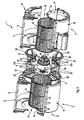
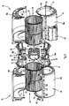
Eine erfindungsgemäße Doppel-Gebläseanordnung 1 besteht aus zwei beidseitig saugenden Radialgebläsen 2, 3, die koaxial von einem gemeinsamen, etwa mittig dazwischen angeordneten Elektromotor 4 angetrieben werden. Jedes Radialgebläse 2, 3 weist zwei axiale, gegenüberliegende Luftansaugöffnungen 6 sowie eine radiale bzw. tangentiale Luftausblasöffnung 8 auf. Der Elektromotor 4 weist eine den Motor durchgreifende, beidseitig aus dem Motor 4 hervorstehende Motorwelle 10 auf und bildet zusammen mit zwei an den Enden der Motorwelle 10 gehalterten Laufrädem 12 eine Lüfterbaugruppe 14. Diese Einheit ist vor allem in den
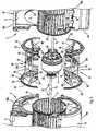
Erfindungsgemäß besteht diese Gehäusebaugruppe 16 aus zwei separaten, vorzugsweise gleichartigen Gebläsegehäusen (Spiralgehäusen) 18 zur Aufnahme jeweils eines der beiden Laufräder 12 sowie aus einem separaten Trägerelement 20 zur lagemden Aufnahme der Lüfterbaugruppe 14 im Bereich des Elektromotors 4. Dabei sind gemäß
Hierzu ist in bevorzugter Ausgestaltung der Erfindung vorgesehen, dass das Trägerelement 20 mit jedem der beiden Gebläsegehäuse 18 über eine die jeweilige Luftansaugöffnung 6 umschließende Formschlußverbindung nach Art einer Nut/Federverbindung mit radialem Eingriff verbunden ist. Dazu ist jedes Gebläsegehäuse 18 in zwei die Luftansaugöffnungen 6 diametral teilende Gehäuseteile 18a und 18b geteilt. Das Trägerelement 20 weist zwei gegenüberliegende ringförmige Verbindungsabschnitte 22 derart auf, dass die Gehäuseteile 18a, b jedes Gebläsegehäuses 18 unter formschlüssigem Einschluß des jeweiligen Verbindungsabschnittes 22 des Trägerelementes 20 zusammengefügt werden können. In den dargestellten, bevorzugten Ausführungen besteht jede formschlüssige Nut/Federverbindung einerseits aus einer Radialnut 24 des jeweiligen Gebläsegehäuses 18, die die jeweilige Luftansaugöffnung 6 umschließt, und andererseits aus einem Radialsteg 26 des Verbindungsabschnittes 22 des Trägerelementes 20. Aufgrund der Kreisform ist es hierbei vorteilhaft, wenn zur Sicherung gegen Relativverdrehungen beispielsweise zusätzliche radiale Ansätze 28 des Radialsteges 26 in korrespondierende radiale Ausnehmungen 30 innerhalb der jeweiligen Radialnut 24 eingreifen (siehe insbesondere
Bei den dargestellten Ausführungen ist jedes Gebläsegehäuse 18 so in die Gehäuseteile 18a, b geteilt, dass auch die Luftausblasöffnung 8 jeweils geteilt ist. Bei der dargestellten Anordnung im Raum handelt es sich somit etwa um eine "horizontale" Teilung. Es ist aber auch jede andere Teilung, beispielsweise "vertikal" möglich.In the illustrated embodiments, each
Es ist vorteilhaft, wenn die ringförmigen Verbindungsabschnitte 22 des Trägerelementes 20 aufgrund ihrer Anordnung im Umfangsbereich der jeweiligen Luftansaugöffnung 6 jeweils einen düsenartig in Ansaugrichtung nach innen gewölbten Umfangsrand 32 aufweisen; siehe dazu insbesondere
Mit Vorteil können die beiden Gebläsegehäuse 18 identisch ausgebildet sein. Dabei kann jedes Gebläsegehäuse 18 im Bereich seiner von dem Elektromotor 4 wegweisenden, außenseitigen Luftansaugöffnung 6 einen düsenartigen Einlaßring 34 aufweisen, der dann - analog zur beschriebenen Verbindung des Gebläsegehäuses 18 mit dem Trägerelement 20 - über eine entsprechende Formschlußverbindung innerhalb der Ansaugöffnung 6 gehalten ist.Advantageously, the two
Wie sich nun besonders aus den Explosionsdarstellungen in
Das Trägerelement 20 weist in seinem axial gesehen etwa mittigen Bereich einen im Wesentlichen ringförmigen, den Bereich des Elektromotors 4 umschließenden Trägerabschnitt 36 auf, der mit den beidseitigen Verbindungsabschntten 22 über etwa axiale bzw. achsparallele und/oder schräg zur Achse geneigt verlaufende Verbindungsstreben 38 verbunden ist. Die lagernde Aufnahme der Lüfterbaugruppe 14 unterscheidet sich bei den dargestellten Ausführungen. Gemeinsam ist aber, dass vorteilhafterweise die Lüfterbaugruppe 14 über schwingungsentkoppelnde, elastische Lagerelemente 40 bzw. schwingungsisolierende Elemente 50 in dem Trägerelement 20 gelagert ist.The
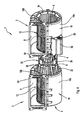
Bei der bevorzugten Ausführung gemäß
Bei der Ausführung gemäß
Bei der Ausführung gemäß
Als weiterer wichtiger Aspekt der Erfindung ist vorgesehen, dass die Gehäuseteile 18a, 18b der Gebläsegehäuse 18 und/oder die Trägerteile 20a, 20b des Trägerelementes 20 im Wesentlichen schraubenlos, und zwar insbesondere über Klammerelemente 52 oder dergleichen lösbar zusammengefügt sind. Einige dieser Klammerelemente 52 sind insbesondere in
Schließlich sei erwähnt, dass die Gebläsegehäuse 18 jeweils einen die Luftausblasöffnung 8 umschließenden, in den dargestellten Ausführungen etwa rechteckigen Montageflansch 54 zur Befestigung, insbesondere Schraubbefestigung, an einer nicht dargestellten Konsole aufweisen.Finally, it should be mentioned that the
Das Trägerelement 20 bzw. seine Trägerteile 20a, 20b besteht vorzugsweise aus Kunststoff, jedoch ist auch eine Ausführung aus Metall, insbesondere Alu-Druckguss, möglich. Entsprechendes gilt auch für die Gebläsegehäuse 18 bzw. deren Gehäuseteile 18a, 18b.The
Im Folgenden soll noch kurz der Ablauf der Montage der Einzelteile erläutert werden.In the following, the sequence of assembly of the individual parts will be briefly explained.
Bei den Ausführungen gemäß
Bei der Ausführung gemäß
Zum elektrischen Anschluß des Elektromotors 4 kann gemäß
Die Erfindung ist nicht auf die dargestellten und beschriebenen Ausführungsbeispiele beschränkt, sondern umfaßt auch alle im Sinne der Erfindung gleichwirkenden Ausführungen.The invention is not limited to the illustrated and described embodiments, but also includes all the same in the context of the invention embodiments.
Claims (17)
- Dual-fan arrangement (1) with two radial fans (2, 3) coaxially driven by a common electric motor (4), which radial fans comprise two opposing axial air intake openings (6) respectively and a radial or tangential air exhaust opening (8), consisting of a fan assembly (14) composed of the electric motor (4) and two blower wheels (12) mounted on both end surfaces of the motor shaft (10) and a housing assembly (16) receiving the fan assembly (14), the housing assembly (16) consisting of two separate fan housings (18) for receiving one of the two blower wheels (12) respectively and a separate support element (20) for supportingly receiving the fan assembly (14) in the region of the electric motor (4), the two fan housings (18) being connected, by means of the support element (20), to one another and to the fan assembly (14) to form a preassembled comprehensive assembly, characterised in that each fan housing (18) can be fixed to a bracket in such a way that the fan assembly (14) is suspended, with the electric motor (4) and the blower wheels (12), by means of the support element (20) connecting the fan housing (18), from the two fan housings (18) which are fixed to the bracket or are to be fixed to the bracket.
- Dual-fan arrangement according to claim 1, characterised in that the fan housings (18) each comprise a mounting flange (54) which surrounds the air exhaust opening (8) for fixing to the bracket.
- Dual-fan arrangement according to either claim 1 or claim 2, characterised in that the support element (20) is connected to each of the two fan housings (18) by means of an interlocking connection of the tongue and groove type which surrounds the respective air intake opening (6) and engages radially.
- Dual-fan arrangement according to any one of claims 1 to 3, characterised in that each fan housing (18) is divided into two housing parts (18a, 18b) which separate the air intake openings (6) and the support element (20) comprises two annular connecting portions (22) in such a way that the housing parts (18a, 18b) of each fan housing (18) are joined or can be joined by interlockingly surrounding the respective connection portion (22) of the support element (20).
- Dual-fan arrangement according to either claim 3 or claim 4, characterised in that the housing parts (18a, 18b), in the region of at least one of their air intake openings (6) respectively, comprise a radial groove (24) surrounding the air intake opening for receiving a corresponding radial ridge (26) of the connecting portion (22) of the support element (20).
- Dual-fan arrangement according to either claim 4 or claim 5, characterised in that the housing parts (18a, 18b) of each fan housing (18) also divide the air exhaust opening (8).
- Dual-fan arrangement according to any one of claims 4 to 6, characterised in that the annular connecting portions (22) of the support element (20) respectively comprise a nozzle-like peripheral edge (2) curved in the intake direction.
- Dual-fan arrangement according to any one of claims 1 to 7, characterised in that the two fan housings (18) are identical.
- Dual-fan arrangement according to claim 8, characterised in that each fan housing (18), in the region of its external air intake opening (6, 7) which points away from the electric motor (4), comprises a nozzle-like intake ring (34) which is held - similarly to the connection between the fan housing (18) and the support element (20) - by means of an interlocking connection.
- Dual-fan arrangement according to any one of claims 1 to 9, characterised in that the support element (2) is divided into two - in particular identically configured - support parts (20a, 20b) which are connected or can be connected to one another when the electric motor (4) is supportingly received.
- Dual-fan arrangement according to any one of claims 1 to 10, characterised in that the fan assembly (14) is mounted in the support element (20) by means of vibration decoupling or vibration insulating mounting elements (40).
- Dual-fan arrangement according to any one of claims 4 to 11, characterised in that the support element (20), in its approximate axial centre region, comprises a support portion (36) which surrounds the region of the electric motor (4), which support portion is connected to the connecting portions (22) by means of connecting struts (38).
- Dual-fan arrangement according to any one of claims 1 to 12, characterised in that the support element (20) respectively comprises a mounting portion (42) for receiving a mounting element (40) in the regions which lie axially on both sides of the electric motor (4).
- Dual-fan arrangement according to any one of claims 1 to 12, characterised in that there is fixed on at least one stator bushing of the electric motor (4) a support element (46) which radially and axially overlaps the electric motor (4) with spoke-shaped mounting arms (48), resilient vibration insulating elements (50) being arranged between the support element (20) and the mounting arms (48).
- Dual-fan arrangement according to any one of claims 1 to 14, characterised in that the electric motor (4) is an external rotor motor.
- Dual-fan arrangement according to any one of claims 1 to 14, characterised in that the electric motor (4) is an internal rotor motor.
- Dual-fan arrangement according to any one of claims 4 to 16, characterised in that the housing parts (18a, 18b) of the fan housing (18) and/or the support parts (20a, 20b) of the support element (20) are detachably joined together substantially without screws and, in particular, by means of clamping elements (52) or the like.
Applications Claiming Priority (2)
| Application Number | Priority Date | Filing Date | Title |
|---|---|---|---|
| DE20308886U DE20308886U1 (en) | 2003-06-05 | 2003-06-05 | Double-blower assembly |
| DE20308886U | 2003-06-05 |
Publications (2)
| Publication Number | Publication Date |
|---|---|
| EP1484509A1 EP1484509A1 (en) | 2004-12-08 |
| EP1484509B1 true EP1484509B1 (en) | 2008-03-12 |
Family
ID=33154659
Family Applications (1)
| Application Number | Title | Priority Date | Filing Date |
|---|---|---|---|
| EP04010404A Expired - Lifetime EP1484509B1 (en) | 2003-06-05 | 2004-05-03 | Dual blower unit |
Country Status (4)
| Country | Link |
|---|---|
| EP (1) | EP1484509B1 (en) |
| AT (1) | ATE389116T1 (en) |
| DE (2) | DE20308886U1 (en) |
| ES (1) | ES2301894T3 (en) |
Cited By (8)
| Publication number | Priority date | Publication date | Assignee | Title |
|---|---|---|---|---|
| EP2653729A1 (en) | 2012-04-20 | 2013-10-23 | ebm-papst Mulfingen GmbH & Co. KG | Radial fan with an auxiliary electromagnetically protected casing for the control electronics |
| US8839815B2 (en) | 2011-12-15 | 2014-09-23 | Honeywell International Inc. | Gas valve with electronic cycle counter |
| US8899264B2 (en) | 2011-12-15 | 2014-12-02 | Honeywell International Inc. | Gas valve with electronic proof of closure system |
| US8905063B2 (en) | 2011-12-15 | 2014-12-09 | Honeywell International Inc. | Gas valve with fuel rate monitor |
| US8947242B2 (en) | 2011-12-15 | 2015-02-03 | Honeywell International Inc. | Gas valve with valve leakage test |
| US9074770B2 (en) | 2011-12-15 | 2015-07-07 | Honeywell International Inc. | Gas valve with electronic valve proving system |
| US9234661B2 (en) | 2012-09-15 | 2016-01-12 | Honeywell International Inc. | Burner control system |
| US9557059B2 (en) | 2011-12-15 | 2017-01-31 | Honeywell International Inc | Gas valve with communication link |
Families Citing this family (19)
| Publication number | Priority date | Publication date | Assignee | Title |
|---|---|---|---|---|
| ITTO20050405A1 (en) * | 2005-06-10 | 2006-12-11 | Denso Thermal Systems Spa | DOUBLE FAN VENTILATION GROUP FOR VEHICLES |
| ITBO20070382A1 (en) * | 2007-05-31 | 2008-12-01 | Spal Automotive Srl | ELECTRIC |
| EP2236838B1 (en) * | 2009-03-25 | 2016-09-21 | ebm-papst Mulfingen GmbH & Co. KG | Radial fan |
| CN102865239A (en) * | 2011-07-04 | 2013-01-09 | 陈平亮 | Air blower capable of omni-directionally blowing out air for large space |
| US9995486B2 (en) | 2011-12-15 | 2018-06-12 | Honeywell International Inc. | Gas valve with high/low gas pressure detection |
| US9846440B2 (en) | 2011-12-15 | 2017-12-19 | Honeywell International Inc. | Valve controller configured to estimate fuel comsumption |
| US9851103B2 (en) | 2011-12-15 | 2017-12-26 | Honeywell International Inc. | Gas valve with overpressure diagnostics |
| US9835265B2 (en) | 2011-12-15 | 2017-12-05 | Honeywell International Inc. | Valve with actuator diagnostics |
| US10422531B2 (en) | 2012-09-15 | 2019-09-24 | Honeywell International Inc. | System and approach for controlling a combustion chamber |
| DE102013204144A1 (en) * | 2013-03-11 | 2014-09-11 | BSH Bosch und Siemens Hausgeräte GmbH | Housing for a radial fan of an extractor hood |
| EP2868970B1 (en) | 2013-10-29 | 2020-04-22 | Honeywell Technologies Sarl | Regulating device |
| US10024439B2 (en) | 2013-12-16 | 2018-07-17 | Honeywell International Inc. | Valve over-travel mechanism |
| US9841122B2 (en) | 2014-09-09 | 2017-12-12 | Honeywell International Inc. | Gas valve with electronic valve proving system |
| US9645584B2 (en) | 2014-09-17 | 2017-05-09 | Honeywell International Inc. | Gas valve with electronic health monitoring |
| US10503181B2 (en) | 2016-01-13 | 2019-12-10 | Honeywell International Inc. | Pressure regulator |
| US10564062B2 (en) | 2016-10-19 | 2020-02-18 | Honeywell International Inc. | Human-machine interface for gas valve |
| KR20180122258A (en) | 2017-05-02 | 2018-11-12 | 엘지전자 주식회사 | Local ventilation equipment and blower therein |
| US11073281B2 (en) | 2017-12-29 | 2021-07-27 | Honeywell International Inc. | Closed-loop programming and control of a combustion appliance |
| US10697815B2 (en) | 2018-06-09 | 2020-06-30 | Honeywell International Inc. | System and methods for mitigating condensation in a sensor module |
Family Cites Families (5)
| Publication number | Priority date | Publication date | Assignee | Title |
|---|---|---|---|---|
| CH381798A (en) * | 1960-06-17 | 1964-09-15 | Wirz Paul | Fan unit |
| US3780411A (en) * | 1972-10-19 | 1973-12-25 | Case Co J I | Method of making blower housing assembly |
| US4165953A (en) * | 1977-10-17 | 1979-08-28 | Deere & Company | Blower assembly |
| DE3234006A1 (en) * | 1982-09-14 | 1984-03-22 | Robert Bosch Gmbh, 7000 Stuttgart | Blower |
| US5403163A (en) * | 1990-08-20 | 1995-04-04 | Molded Products Company | Motor mount for blower housing |
-
2003
- 2003-06-05 DE DE20308886U patent/DE20308886U1/en not_active Expired - Lifetime
-
2004
- 2004-05-03 AT AT04010404T patent/ATE389116T1/en not_active IP Right Cessation
- 2004-05-03 ES ES04010404T patent/ES2301894T3/en not_active Expired - Lifetime
- 2004-05-03 EP EP04010404A patent/EP1484509B1/en not_active Expired - Lifetime
- 2004-05-03 DE DE502004006459T patent/DE502004006459D1/en active Active
Cited By (8)
| Publication number | Priority date | Publication date | Assignee | Title |
|---|---|---|---|---|
| US8839815B2 (en) | 2011-12-15 | 2014-09-23 | Honeywell International Inc. | Gas valve with electronic cycle counter |
| US8899264B2 (en) | 2011-12-15 | 2014-12-02 | Honeywell International Inc. | Gas valve with electronic proof of closure system |
| US8905063B2 (en) | 2011-12-15 | 2014-12-09 | Honeywell International Inc. | Gas valve with fuel rate monitor |
| US8947242B2 (en) | 2011-12-15 | 2015-02-03 | Honeywell International Inc. | Gas valve with valve leakage test |
| US9074770B2 (en) | 2011-12-15 | 2015-07-07 | Honeywell International Inc. | Gas valve with electronic valve proving system |
| US9557059B2 (en) | 2011-12-15 | 2017-01-31 | Honeywell International Inc | Gas valve with communication link |
| EP2653729A1 (en) | 2012-04-20 | 2013-10-23 | ebm-papst Mulfingen GmbH & Co. KG | Radial fan with an auxiliary electromagnetically protected casing for the control electronics |
| US9234661B2 (en) | 2012-09-15 | 2016-01-12 | Honeywell International Inc. | Burner control system |
Also Published As
| Publication number | Publication date |
|---|---|
| ATE389116T1 (en) | 2008-03-15 |
| EP1484509A1 (en) | 2004-12-08 |
| ES2301894T3 (en) | 2008-07-01 |
| DE502004006459D1 (en) | 2008-04-24 |
| DE20308886U1 (en) | 2004-10-14 |
Similar Documents
| Publication | Publication Date | Title |
|---|---|---|
| EP1484509B1 (en) | Dual blower unit | |
| DE19936644B4 (en) | Electric air pump for motor vehicles | |
| EP1094224B1 (en) | Radial fan | |
| EP2242930B1 (en) | Compact fan | |
| EP0985829B1 (en) | Housing for radial blower | |
| DE102006057087B3 (en) | Injection-molded plastic rotor for radial blower, is produced with integral hub including concentric recesses for balancing weights at differing axial and radial positions | |
| EP1470320B1 (en) | Fixing device for a turbo-supercharger | |
| EP3101350B1 (en) | Fan unit for an extractor hood and extractor hood | |
| DE19850461A1 (en) | Fan rotor for fan powered by electric motor | |
| CH654379A5 (en) | SMALL BLOWER. | |
| EP1664539B1 (en) | Inner gear-wheel pump comprising reinforced channels | |
| DE19636820C2 (en) | Device for receiving an engine mounting of an internal combustion engine | |
| DE4137465C2 (en) | One-sided attachment of a stator of a brushless DC motor to a housing part | |
| EP0358731B1 (en) | Axial fan | |
| DE4222264A1 (en) | Electric fan mounting for vehicle radiator - has complete fan unit, with mounting duct clipped to cowl on radiator. | |
| EP0338549B1 (en) | Safety device for a fan of a combustion engine | |
| DE19946849B4 (en) | Canned motor pump | |
| DE2001395B2 (en) | Lateral duct blower with twin blade impeller - has cooling fans either side and air guides with flanges for multistage stacking | |
| EP0826262A1 (en) | Low-noise electric motor, especially commutator motor | |
| EP0826263B1 (en) | Low-noise electric motor, especially commutator motor | |
| DE2724829C2 (en) | Cross-flow radial fan unit | |
| EP0855782A1 (en) | Low noise electric motor, notably for a fan of a motor vehicle | |
| DE4203689C2 (en) | Electric motor with screwless frame structure | |
| DE202013104348U1 (en) | Modularized cross-flow fan device | |
| EP1030432A2 (en) | Electric motor |
Legal Events
| Date | Code | Title | Description |
|---|---|---|---|
| PUAI | Public reference made under article 153(3) epc to a published international application that has entered the european phase |
Free format text: ORIGINAL CODE: 0009012 |
|
| AK | Designated contracting states |
Kind code of ref document: A1 Designated state(s): AT BE BG CH CY CZ DE DK EE ES FI FR GB GR HU IE IT LI LU MC NL PL PT RO SE SI SK TR |
|
| AX | Request for extension of the european patent |
Extension state: AL HR LT LV MK |
|
| 17P | Request for examination filed |
Effective date: 20041026 |
|
| AKX | Designation fees paid |
Designated state(s): AT BE BG CH CY CZ DE DK EE ES FI FR GB GR HU IE IT LI LU MC NL PL PT RO SE SI SK TR |
|
| 17Q | First examination report despatched |
Effective date: 20060920 |
|
| GRAP | Despatch of communication of intention to grant a patent |
Free format text: ORIGINAL CODE: EPIDOSNIGR1 |
|
| GRAS | Grant fee paid |
Free format text: ORIGINAL CODE: EPIDOSNIGR3 |
|
| GRAA | (expected) grant |
Free format text: ORIGINAL CODE: 0009210 |
|
| AK | Designated contracting states |
Kind code of ref document: B1 Designated state(s): AT BE BG CH CY CZ DE DK EE ES FI FR GB GR HU IE IT LI LU MC NL PL PT RO SE SI SK TR |
|
| REG | Reference to a national code |
Ref country code: GB Ref legal event code: FG4D Free format text: NOT ENGLISH |
|
| REG | Reference to a national code |
Ref country code: CH Ref legal event code: EP |
|
| REG | Reference to a national code |
Ref country code: IE Ref legal event code: FG4D Free format text: LANGUAGE OF EP DOCUMENT: GERMAN |
|
| REF | Corresponds to: |
Ref document number: 502004006459 Country of ref document: DE Date of ref document: 20080424 Kind code of ref document: P |
|
| REG | Reference to a national code |
Ref country code: ES Ref legal event code: FG2A Ref document number: 2301894 Country of ref document: ES Kind code of ref document: T3 |
|
| PG25 | Lapsed in a contracting state [announced via postgrant information from national office to epo] |
Ref country code: FI Free format text: LAPSE BECAUSE OF FAILURE TO SUBMIT A TRANSLATION OF THE DESCRIPTION OR TO PAY THE FEE WITHIN THE PRESCRIBED TIME-LIMIT Effective date: 20080312 |
|
| ET | Fr: translation filed | ||
| NLV1 | Nl: lapsed or annulled due to failure to fulfill the requirements of art. 29p and 29m of the patents act | ||
| PG25 | Lapsed in a contracting state [announced via postgrant information from national office to epo] |
Ref country code: PL Free format text: LAPSE BECAUSE OF FAILURE TO SUBMIT A TRANSLATION OF THE DESCRIPTION OR TO PAY THE FEE WITHIN THE PRESCRIBED TIME-LIMIT Effective date: 20080312 Ref country code: SI Free format text: LAPSE BECAUSE OF FAILURE TO SUBMIT A TRANSLATION OF THE DESCRIPTION OR TO PAY THE FEE WITHIN THE PRESCRIBED TIME-LIMIT Effective date: 20080312 |
|
| REG | Reference to a national code |
Ref country code: IE Ref legal event code: FD4D |
|
| PG25 | Lapsed in a contracting state [announced via postgrant information from national office to epo] |
Ref country code: SK Free format text: LAPSE BECAUSE OF FAILURE TO SUBMIT A TRANSLATION OF THE DESCRIPTION OR TO PAY THE FEE WITHIN THE PRESCRIBED TIME-LIMIT Effective date: 20080312 Ref country code: PT Free format text: LAPSE BECAUSE OF FAILURE TO SUBMIT A TRANSLATION OF THE DESCRIPTION OR TO PAY THE FEE WITHIN THE PRESCRIBED TIME-LIMIT Effective date: 20080818 Ref country code: SE Free format text: LAPSE BECAUSE OF FAILURE TO SUBMIT A TRANSLATION OF THE DESCRIPTION OR TO PAY THE FEE WITHIN THE PRESCRIBED TIME-LIMIT Effective date: 20080612 |
|
| PG25 | Lapsed in a contracting state [announced via postgrant information from national office to epo] |
Ref country code: NL Free format text: LAPSE BECAUSE OF FAILURE TO SUBMIT A TRANSLATION OF THE DESCRIPTION OR TO PAY THE FEE WITHIN THE PRESCRIBED TIME-LIMIT Effective date: 20080312 Ref country code: RO Free format text: LAPSE BECAUSE OF FAILURE TO SUBMIT A TRANSLATION OF THE DESCRIPTION OR TO PAY THE FEE WITHIN THE PRESCRIBED TIME-LIMIT Effective date: 20080312 |
|
| BERE | Be: lapsed |
Owner name: EBM-PAPST MULFINGEN G.M.B.H. & CO.KG Effective date: 20080531 |
|
| PG25 | Lapsed in a contracting state [announced via postgrant information from national office to epo] |
Ref country code: MC Free format text: LAPSE BECAUSE OF NON-PAYMENT OF DUE FEES Effective date: 20080531 |
|
| REG | Reference to a national code |
Ref country code: CH Ref legal event code: PL |
|
| PLBE | No opposition filed within time limit |
Free format text: ORIGINAL CODE: 0009261 |
|
| STAA | Information on the status of an ep patent application or granted ep patent |
Free format text: STATUS: NO OPPOSITION FILED WITHIN TIME LIMIT |
|
| PG25 | Lapsed in a contracting state [announced via postgrant information from national office to epo] |
Ref country code: DK Free format text: LAPSE BECAUSE OF FAILURE TO SUBMIT A TRANSLATION OF THE DESCRIPTION OR TO PAY THE FEE WITHIN THE PRESCRIBED TIME-LIMIT Effective date: 20080312 Ref country code: LI Free format text: LAPSE BECAUSE OF NON-PAYMENT OF DUE FEES Effective date: 20080531 Ref country code: EE Free format text: LAPSE BECAUSE OF FAILURE TO SUBMIT A TRANSLATION OF THE DESCRIPTION OR TO PAY THE FEE WITHIN THE PRESCRIBED TIME-LIMIT Effective date: 20080312 Ref country code: IE Free format text: LAPSE BECAUSE OF FAILURE TO SUBMIT A TRANSLATION OF THE DESCRIPTION OR TO PAY THE FEE WITHIN THE PRESCRIBED TIME-LIMIT Effective date: 20080312 Ref country code: CH Free format text: LAPSE BECAUSE OF NON-PAYMENT OF DUE FEES Effective date: 20080531 |
|
| 26N | No opposition filed |
Effective date: 20081215 |
|
| PG25 | Lapsed in a contracting state [announced via postgrant information from national office to epo] |
Ref country code: BE Free format text: LAPSE BECAUSE OF NON-PAYMENT OF DUE FEES Effective date: 20080531 |
|
| PG25 | Lapsed in a contracting state [announced via postgrant information from national office to epo] |
Ref country code: BG Free format text: LAPSE BECAUSE OF FAILURE TO SUBMIT A TRANSLATION OF THE DESCRIPTION OR TO PAY THE FEE WITHIN THE PRESCRIBED TIME-LIMIT Effective date: 20080612 |
|
| PG25 | Lapsed in a contracting state [announced via postgrant information from national office to epo] |
Ref country code: AT Free format text: LAPSE BECAUSE OF NON-PAYMENT OF DUE FEES Effective date: 20080503 |
|
| PG25 | Lapsed in a contracting state [announced via postgrant information from national office to epo] |
Ref country code: CY Free format text: LAPSE BECAUSE OF FAILURE TO SUBMIT A TRANSLATION OF THE DESCRIPTION OR TO PAY THE FEE WITHIN THE PRESCRIBED TIME-LIMIT Effective date: 20080312 |
|
| PG25 | Lapsed in a contracting state [announced via postgrant information from national office to epo] |
Ref country code: LU Free format text: LAPSE BECAUSE OF NON-PAYMENT OF DUE FEES Effective date: 20080503 Ref country code: HU Free format text: LAPSE BECAUSE OF FAILURE TO SUBMIT A TRANSLATION OF THE DESCRIPTION OR TO PAY THE FEE WITHIN THE PRESCRIBED TIME-LIMIT Effective date: 20080913 |
|
| PG25 | Lapsed in a contracting state [announced via postgrant information from national office to epo] |
Ref country code: TR Free format text: LAPSE BECAUSE OF FAILURE TO SUBMIT A TRANSLATION OF THE DESCRIPTION OR TO PAY THE FEE WITHIN THE PRESCRIBED TIME-LIMIT Effective date: 20080312 |
|
| PG25 | Lapsed in a contracting state [announced via postgrant information from national office to epo] |
Ref country code: GR Free format text: LAPSE BECAUSE OF FAILURE TO SUBMIT A TRANSLATION OF THE DESCRIPTION OR TO PAY THE FEE WITHIN THE PRESCRIBED TIME-LIMIT Effective date: 20080613 |
|
| REG | Reference to a national code |
Ref country code: FR Ref legal event code: PLFP Year of fee payment: 13 |
|
| REG | Reference to a national code |
Ref country code: FR Ref legal event code: PLFP Year of fee payment: 14 |
|
| REG | Reference to a national code |
Ref country code: DE Ref legal event code: R082 Ref document number: 502004006459 Country of ref document: DE Representative=s name: PATENTANWAELTE STAEGER & SPERLING PARTNERSCHAF, DE |
|
| REG | Reference to a national code |
Ref country code: FR Ref legal event code: PLFP Year of fee payment: 15 |
|
| PGFP | Annual fee paid to national office [announced via postgrant information from national office to epo] |
Ref country code: IT Payment date: 20230531 Year of fee payment: 20 Ref country code: FR Payment date: 20230517 Year of fee payment: 20 Ref country code: ES Payment date: 20230621 Year of fee payment: 20 Ref country code: DE Payment date: 20230519 Year of fee payment: 20 Ref country code: CZ Payment date: 20230421 Year of fee payment: 20 |
|
| PGFP | Annual fee paid to national office [announced via postgrant information from national office to epo] |
Ref country code: GB Payment date: 20230522 Year of fee payment: 20 |