EP1502828A1 - Curtain-shield airbag clip and assemblies using the clip - Google Patents
Curtain-shield airbag clip and assemblies using the clip Download PDFInfo
- Publication number
- EP1502828A1 EP1502828A1 EP04018259A EP04018259A EP1502828A1 EP 1502828 A1 EP1502828 A1 EP 1502828A1 EP 04018259 A EP04018259 A EP 04018259A EP 04018259 A EP04018259 A EP 04018259A EP 1502828 A1 EP1502828 A1 EP 1502828A1
- Authority
- EP
- European Patent Office
- Prior art keywords
- pin
- bore
- flange
- bushing
- leg
- Prior art date
- Legal status (The legal status is an assumption and is not a legal conclusion. Google has not performed a legal analysis and makes no representation as to the accuracy of the status listed.)
- Granted
Links
- 230000000712 assembly Effects 0.000 title description 3
- 238000000429 assembly Methods 0.000 title description 3
- 238000005192 partition Methods 0.000 claims abstract description 26
- 230000037431 insertion Effects 0.000 claims description 11
- 238000003780 insertion Methods 0.000 claims description 11
- 230000008878 coupling Effects 0.000 abstract description 4
- 238000010168 coupling process Methods 0.000 abstract description 4
- 238000005859 coupling reaction Methods 0.000 abstract description 4
- 230000000694 effects Effects 0.000 description 6
- 238000006243 chemical reaction Methods 0.000 description 3
- 238000010079 rubber tapping Methods 0.000 description 3
- 210000000078 claw Anatomy 0.000 description 2
- 238000010586 diagram Methods 0.000 description 2
- 230000003292 diminished effect Effects 0.000 description 2
- 239000000463 material Substances 0.000 description 2
- 239000007787 solid Substances 0.000 description 2
- 238000003466 welding Methods 0.000 description 2
- 230000007812 deficiency Effects 0.000 description 1
- 238000000465 moulding Methods 0.000 description 1
- 230000035939 shock Effects 0.000 description 1
- 238000000638 solvent extraction Methods 0.000 description 1
- 238000011179 visual inspection Methods 0.000 description 1
Images


Classifications
-
- B—PERFORMING OPERATIONS; TRANSPORTING
- B60—VEHICLES IN GENERAL
- B60R—VEHICLES, VEHICLE FITTINGS, OR VEHICLE PARTS, NOT OTHERWISE PROVIDED FOR
- B60R21/00—Arrangements or fittings on vehicles for protecting or preventing injuries to occupants or pedestrians in case of accidents or other traffic risks
- B60R21/02—Occupant safety arrangements or fittings, e.g. crash pads
- B60R21/16—Inflatable occupant restraints or confinements designed to inflate upon impact or impending impact, e.g. air bags
- B60R21/20—Arrangements for storing inflatable members in their non-use or deflated condition; Arrangement or mounting of air bag modules or components
- B60R21/213—Arrangements for storing inflatable members in their non-use or deflated condition; Arrangement or mounting of air bag modules or components in vehicle roof frames or pillars
-
- F—MECHANICAL ENGINEERING; LIGHTING; HEATING; WEAPONS; BLASTING
- F16—ENGINEERING ELEMENTS AND UNITS; GENERAL MEASURES FOR PRODUCING AND MAINTAINING EFFECTIVE FUNCTIONING OF MACHINES OR INSTALLATIONS; THERMAL INSULATION IN GENERAL
- F16B—DEVICES FOR FASTENING OR SECURING CONSTRUCTIONAL ELEMENTS OR MACHINE PARTS TOGETHER, e.g. NAILS, BOLTS, CIRCLIPS, CLAMPS, CLIPS OR WEDGES; JOINTS OR JOINTING
- F16B19/00—Bolts without screw-thread; Pins, including deformable elements; Rivets
- F16B19/04—Rivets; Spigots or the like fastened by riveting
- F16B19/08—Hollow rivets; Multi-part rivets
- F16B19/10—Hollow rivets; Multi-part rivets fastened by expanding mechanically
- F16B19/1027—Multi-part rivets
- F16B19/1036—Blind rivets
- F16B19/1081—Blind rivets fastened by a drive-pin
-
- B—PERFORMING OPERATIONS; TRANSPORTING
- B60—VEHICLES IN GENERAL
- B60R—VEHICLES, VEHICLE FITTINGS, OR VEHICLE PARTS, NOT OTHERWISE PROVIDED FOR
- B60R21/00—Arrangements or fittings on vehicles for protecting or preventing injuries to occupants or pedestrians in case of accidents or other traffic risks
- B60R21/02—Occupant safety arrangements or fittings, e.g. crash pads
- B60R21/16—Inflatable occupant restraints or confinements designed to inflate upon impact or impending impact, e.g. air bags
- B60R21/23—Inflatable members
- B60R21/231—Inflatable members characterised by their shape, construction or spatial configuration
- B60R21/232—Curtain-type airbags deploying mainly in a vertical direction from their top edge
-
- F—MECHANICAL ENGINEERING; LIGHTING; HEATING; WEAPONS; BLASTING
- F16—ENGINEERING ELEMENTS AND UNITS; GENERAL MEASURES FOR PRODUCING AND MAINTAINING EFFECTIVE FUNCTIONING OF MACHINES OR INSTALLATIONS; THERMAL INSULATION IN GENERAL
- F16B—DEVICES FOR FASTENING OR SECURING CONSTRUCTIONAL ELEMENTS OR MACHINE PARTS TOGETHER, e.g. NAILS, BOLTS, CIRCLIPS, CLAMPS, CLIPS OR WEDGES; JOINTS OR JOINTING
- F16B21/00—Means for preventing relative axial movement of a pin, spigot, shaft or the like and a member surrounding it; Stud-and-socket releasable fastenings
- F16B21/06—Releasable fastening devices with snap-action
- F16B21/07—Releasable fastening devices with snap-action in which the socket has a resilient part
- F16B21/071—Releasable fastening devices with snap-action in which the socket has a resilient part the socket being integrally formed with a component to be fasted, e.g. a sheet, plate or strip
Definitions
- the present invention relates to a clip for attaching an airbag attaching member for a curtain-shield airbag to a body panel and to assemblies using the clip.
- a device for attaching a head-protecting curtain-shield airbag to a body panel is disclosed in Laid-Open Patent Application [TOKKAI] No. 2002-104127, gazette publication (Patent Literature 1).
- This device comprises, a knob, a leg, and an engagement member. By inserting the engagement member and leg of the device into an attachment hole in an airbag attaching member and into an attachment hole in the body panel, and turning the knob, the curtain-shield airbag is attached to the body panel.
- a screw grommet for coupling two panels is disclosed in Laid-Open Patent Application [TOKKAI] No. HI-216109/1989, gazette publication (Patent Literature 2).
- This screw grommet comprises a shaft with a flange at one end.
- a bore for receiving a tapping screw extends through the flange and the shaft.
- Tapered flexible claws project outwardly from the shaft.
- the shaft is inserted through an attachment hole in one panel until one side of the flange abuts that panel; a second panel is abutted with the other side of the flange with an attachment hole aligned with the attachment hole of the first panel; and the screw is threaded into the bore of the grommet through the attachment holes in the panels.
- the flexible claws project outwardly from the shaft to hold the screw grommet in place.
- a clip for attaching a part to a body panel is disclosed in Laid-Open Utility Model Application [JIKKAI] No. S59-141210/1984, gazette publication (Patent Literature 3) and comprises a bushing and a flanged pin that is inserted into the bushing to expand the bushing and hold it on the panel even if there are burrs in a panel attachment hole into which the bushing is inserted.
- Patent Literature 1 With the device for attaching a curtain-shield airbag to a body panel described in TOKKAI 2002-104127, gazette publication (Patent Literature 1), an attachment operation can be performed without the use of tools, but the strength of the attachment is not high. Since the airbag deploys very rapidly when activated, the reactive force on the device is large, and there is a danger of detachment.
- curtain-shield airbag attachment device With another curtain-shield airbag attachment device, a nut is welded to the body panel, and the airbag attaching member of the curtain-shield airbag is attached with a bolt.
- the strength of that attachment is great, but there is the necessity of welding the nut to the body panel, which militates against simplifying automobile assembly operations.
- the curtain-shield airbag must first be provisionally attached to the body panel, and then permanently attached with a bolt, requiring a special structure for the provisional attachment.
- Patent Literature 2 With the screw grommet of TOKKAI No. H1-216109/1989, gazette publication (Patent Literature 2), an operation is required for positioning the second panel and holding it so that the attachment hole thereof is aligned with the bore opening in the flange, and a tapping screw screwing operation is also required.
- Patent Literature 3 attachment is maintained even if there are burrs in the edge of the attachment hole, but both the bushing and the pin must be formed in a special shape so as to suppress the effects of burrs.
- Patent Literature 2 moreover, there is no suggestion of the screw grommet thereof being usable in attaching a curtain-shield airbag, nor in Patent Literature 3 is there any suggestion of the clip thereof being usable in attaching a curtain-shield airbag. More particularly, there is no teaching as to how to cope with the reaction force against the clip which accompanies the rapid deployment of the airbag when activated.
- An object of the present invention is to provide a curtain-shield airbag attachment clip that avoids or overcomes the deficiencies of the prior art, and to provide assemblies using the clip. More particularly, the invention provides high attachment strength, avoids the need for welding a nut to a body panel, provides for simple provisional attachment, avoids the need for installing a tapping screw, and has other advantages as well.
- a clip in accordance with the invention comprises two components, namely, a pin and a bushing for receiving the pin.
- the bushing comprises a leg that is inserted into an attachment hole in an airbag attaching member and into an attachment hole in a body panel, and a flange integral with the leg for holding the airbag attaching member in cooperation with the body panel.
- the bushing has a bore extending from an opening in the flange and into the leg for receiving the pin therein.
- the leg is provided, exteriorly, with a resiliently mounted engagement piece for maintaining attachment of the bushing to an airbag attaching member and a body panel having holes through which the leg of the bushing is inserted.
- the pin can be inserted into the bore of the bushing to be held at a provisional position, at which the engagement piece is able to flex inwardly of the bore in the leg, and a final position at which the engagement piece is prevented from flexing inwardly of the bore.
- the flange has an integral partition plate which forms a partition between the main airbag unit of the curtain-shield airbag and part of the flange at which the bore opening is located.
- Fig. 1 basically diagrams how a curtain-shield airbag 1 is attached in an automobile.
- the curtain-shield airbag 1 which is primarily for protecting the heads of occupants of the automobile, is attached to a body panel 2 at the top of the door windows, from the front to the rear, on the inside of the automobile.
- gas from a compressed gas source 3 an inflator
- the curtain-shield airbag very rapidly deploys toward the lower part of the door windows (in the direction of arrow 5) to protect the heads and other body portions of vehicle occupants.
- the curtain-shield airbag 1 comprises a main airbag unit and airbag attaching members 6.
- the airbag attaching members are secured to a body panel, such as a frame of the automobile, at a plurality of prescribed positions at the top of the door windows.
- the main airbag unit at normal times, is folded small and housed at a fixed position at the top of the door windows.
- Fig. 2 shows a clip 10 relating to the first embodiment of the present invention.
- This clip 10 comprises two components, namely a rod-shaped pin 11 and a bushing 13 for receiving the pin 11.
- the bushing 13 comprises a leg 14 that is inserted into an attachment hole in an airbag attaching member and into an attachment hole in a body panel, and a flange 15 formed integrally with the leg, for holding the airbag attaching member in cooperation with the body panel.
- a bore is formed comprising a flange hole 17 and a shaft hole 18 continuing therefrom, into which the pin 11 can be inserted.
- one or more resiliently mounted engagement pieces 19 are provided, protruding to the outside, and capable of engaging edge regions of an attachment hole in the airbag attaching member 6 and an attachment hole in the body panel 2.
- the configuration is such that, when the pin I 1 is substantially fully inserted into the bore 17, 18, the engagement pieces 19 are put in a permanently fixed condition, with the flexure thereof toward the inside of the shaft hole prevented.
- the engagement pieces When the pin 11 is not deeply in the bore 17, 18, as shown in Fig. 2, the engagement pieces are put in a provisionally fixed condition which allows flexure toward the inside of the shaft hole 18.
- the pin 11 and the bushing are coupled so that they can not be easily separated when in the provisionally fixed condition, as shown in Fig. 2.
- a partition plate 21 stands perpendicularly from the flange edge, so as to provide a partition between the main airbag unit of the curtain-shield airbag 1 and the part of the flange 15 where the opening to the hole 17 is located.
- the bushing 13 is preferably an integral molding formed of hard plastic, comprising the leg 14 for insertion into both an attachment hole in the airbag attaching member 6 of the curtain-shield airbag 1 from an attachment hole in the body panel 2, the flange 15 at one end (the upper end in Figs. 2, 3, 4, and 6) of the leg 14, for holding the airbag attaching member 6 in cooperation with the body panel 2, and the partition plate 21, standing perpendicularly from the flange edge, for partitioning the main airbag unit of the curtain-shield airbag 1 and the main part of the flange 15.
- the flange hole 17 and the shaft hole 18 continuing therefrom to allow insertion of the pin 11.
- the flange 15 is formed so that the surface on the leg 14 side (the lower surface in Figs. 2, 3, 4, and 6) is flat, so that the entirety thereof can abut the airbag attaching member, and so that the bushing holds the airbag attaching member in cooperation with the body panel.
- the opening to hole 17 at the opposite side from the leg 14 (the upper surface in Figs. 2, 3, 4, and 6) is tapered to facilitate reception of a pin.
- the flange 15 is formed as a substantially rectangular rigid plate-shaped body. A number of concavities 22 can be formed in this body, as shown in Fig. 5, to save on material and reduce the weight of the flange, while maintaining the rigidity thereof
- the partition plate 21 stands perpendicularly from the flange, in the direction opposite to the direction in which the leg 14 extends, so as to form a partition between the main airbag unit of the curtain-shield airbag 1 and the opening to hole 17 of the flange 15.
- This partition plate 21 has a certain height and a width that extends across the length of the edge, so as to isolate the main airbag unit from the center part of the flange 15, and has a certain thickness that provides high rigidity. Because of the partition plate 21, when the pin 11 is inserted, there is no extension of the main airbag unit to the center part of the flange 15 where the opening to hole 17 is located, so that any danger of the main airbag unit being drawn in by the pin is eliminated.
- the effects thereof toward the flange 15 can be diminished by the partition plate 21.
- the partition plate 21 is preferably supported by triangular support ribs 23 formed at two other edges of the flange 15 to even more strongly preserve rigidity.
- the leg 14 is formed to a suitable length for attaching the airbag attaching member 6 to the body panel 2.
- the shaft hole 18 of the leg 14 can be formed to any appropriate length so long as the pin 11 can be properly inserted therein.
- the shaft hole passes completely through the leg 14 in the example shown, but the shaft hole may be terminated at some intermediate point in the leg 14.
- the cross-sectional shape of the leg 14 may be circular or rectangular or some other shape, but it should preferably be non-circular so that the leg 14 will not turn after attachment has been effected, in order that the partition plate 21 can be set at a position facing the main airbag unit.
- the leg cross-section is a rectangular shape.
- the cross-section of the shaft hole 18 of the leg 14 can be any appropriate shape that will permit proper insertion of the pin.
- the cross-section of the shaft hole 18 is rectangular, which matches the rectangular cross-section of the leg.
- a pair of guide ribs 25 is formed, to a certain thickness, protruding laterally inside, for guiding the pin 11 inserted into the shaft hole in alignment with the axial core of the shaft hole.
- a pair of resiliently mounted engagement pieces 19 is deployed, protruding laterally to the outside.
- the engagement pieces can effect provisional fixing at the edges of the two attachment holes, i.e. the one in the airbag attaching member and the one in the body panel.
- the engagement pieces 19 are configured so that, when the pin 11 is substantially fully inserted into the bore 17, 18, flexure to the inside is prevented, and, when the pin 11 is not so inserted, flexure to the inside is allowed.
- Each of the engagement pieces 19 is formed with the leg 14 end (lower end in Figs. 2, 3, 4, and 6) as its root and the flange 15 end as its free end. For that reason, as shown in Fig. 3, an inverted U-shaped slit 26 is formed about the periphery of each engagement piece 19. This slit separates the engagement piece from the main body of the leg 14.
- shoulder 27 is formed for engaging edge regions of the attachment holes of both the airbag attaching member and the body panel.
- the engagement piece 19 is formed so as to slope gently from the shoulder 27 toward the tip of the leg, so that the engagement piece does not become an impediment when the leg 14 is inserted into the attachment holes of both the airbag attaching member and the body panel.
- the position of the shoulder 27 is determined suitably to match the thickness of the airbag attaching member and the body panel.
- one or more pawls 29 are formed, extending elastically inside at positions adjacent to the flange 15.
- the pawls are useful for coupling the pin 11 to the bushing 13, while maintaining the provisionally fixed condition at which the engagement pieces 19 of the bushing 13 can flex to the inside of the shaft hole 18.
- the pin 11 will now be described with reference to Fig. 8 and Fig. 2.
- the pin 11 is formed overall in a rod shape.
- a large-diameter head 30 of circular shape, for example, is formed at one end (the upper end in the figures) of a shaft 31 which forms the main body of the pin; and makes such operations as insertion into the bushing 13 easy.
- the shaft 31 and head 30 of the pin 11 are preferably solid (not hollow).
- a permanently fixing engagement part 33 is formed, at a position of intermediate height, for engaging the pawls 29, so as to maintain the permanently fixed condition when the pin 11 has been fully inserted in the bore 17, 18.
- a provisionally fixing engagement part 34 is formed on the shaft 31, in addition.
- Provisional fixing of the clip 10 to the airbag attaching member of the curtain-shield airbag can be accomplished easily by the simple operation of inserting the leg 14 of the bushing 13 into the attachment hole of the airbag attaching member.
- the permanently fixing engagement part 33 is an engagement shoulder formed at a position between the tip (lower end) and the head 30 of the shaft 31, and the provisionally fixing engagement part 34 is an engagement shoulder formed near the tip of the shaft 31.
- Portions of the pin 11 are tapered, as shown in Fig. 8, to facilitate insertion of the pin into the bore of the bushing 13.
- the shaft 31, is preferably solid and of high rigidity, so that, in the permanently fixed condition wherein the shaft 31 of the pin 11 has been deeply inserted into the shaft hole 18 of the leg 14 of the bushing 13, the inner walls of the free ends of the engagement pieces 19 (the ends on the flange 15 side) facing the shaft hole are prevented from flexing to the inside.
- the clip 10 is attached to the airbag attaching member 6 and the body panel 2 with high strength.
- the leg 14 of the clip 10 in the provisionally fixed coupled condition is inserted into the attachment hole 6A of the airbag attaching member 6 for the curtain-shield airbag 1, whereupon the clip 10 is pre-attached to the curtain-shield airbag 1.
- the partition plate 21 will be positioned so as to face the main airbag unit of the curtain-shield airbag 1.
- the partition plate 21 effects a partition between the main airbag unit and the airbag attaching member 6, so that the leg 14 of the bushing 13 can easily be inserted into the attachment hole of the airbag attaching member 6.
- Clips 10 can be attached beforehand, respectively, in the attachment holes of a plurality of airbag attaching members 6 (see Fig. 1), thereby forming a clip-equipped curtain-shield airbag assembly.
- the curtain-shield airbag can be provisionally fixed to the body panel, and the number of operations on the outfitting line can be reduced.
- a support plate 35 for holding the airbag attaching members 6 in cooperation with the flanges 15 can be attached by inserting the legs 14 through attachment holes in the support plate.
- the support plate 35 is formed of thin plate material, and the attachment holes through which the legs 14 pass are formed of such size as to engage the shoulders of the engagement pieces 19 with edge regions of the attachment holes, so that a provisionally fixed condition wherein the airbag attaching members 6 are flush against the flanges 15 is maintained.
- the thickness of the support plate 35 By selecting the thickness of the support plate 35, the total thickness of the attachment regions when the curtain-shield airbag 1 is attached to the body panel 2 can also be suitably adjusted.
- each attachment hole 2A is formed at a prescribed position (position of the airbag attaching members 6 in Fig. 1) in the body panel 2.
- the tip of the leg 14 of each bushing 13 on the curtain-shield airbag 1 to which the clip 10 is pre-attached is aligned with an attachment hole 2A.
- the engagement pieces 19 will engage edge regions of the attachment holes 2A in the body panel 2, and the airbag 1 will be attached to the body panel 2 through the clip 10.
- This condition is the provisionally fixed condition.
- the curtain-shield airbag 1 By having a plurality of clips 10 attached, respectively, at prescribed positions on the curtain-shield airbag 1, and merely inserting the legs 14 into attachment holes 2A formed at corresponding positions (positions of the airbag attaching members 6 in Fig. 1) of the body panel 2, the curtain-shield airbag 1 will be provisionally fixed at a prescribed position on the body panel 2.
- the head 30 of a provisionally fixed pin 11 is inserted by hand, in the direction of arrow 37, into the bushing 13 of each clip 10, and the shaft 31 of the pin 11 is inserted deeply into the shaft hole of the leg 14.
- the tapered configuration of the shaft 31 facilitates insertion of the pin.
- the partition plate 21 effects a partition between the main airbag unit and the center of the flange 15, so that there is no danger of the main body of the airbag 1 being caught and tightened down when the pin 11 is inserted.
- the shaft 31 of the pin 11, due to the strong pressing force toward the head 30, is inserted deeply into the shaft hole 18, with the provisionally fixing engagement part 34 passing the pawls 29, and, when the head 30 of the pin 11 is substantially flush against the flange 15, the pawls 29 engage the permanently fixing engagement part 33 of the shaft 31 at a permanently fixing position, whereupon a permanent fixing condition is effected.
- the shaft 31 is on the inside of the engagement pieces 19, the condition of the engagement pieces 19 is such that they protrude to the outside, with the flexure thereof to the inside prevented; the engagement shoulders 27 are engaged with the body panel 2; and the permanent fixing condition is maintained. Accordingly, the curtain-shield airbag 1 is very strongly attached to the body panel 2.
- the partition plate 21 can cope with the shock of the reaction accompanying the rapid deployment of the airbag when it is activated, and the effects thereof toward the flange 15 side can be diminished.
Abstract
Description
- The present invention relates to a clip for attaching an airbag attaching member for a curtain-shield airbag to a body panel and to assemblies using the clip.
- A device for attaching a head-protecting curtain-shield airbag to a body panel is disclosed in Laid-Open Patent Application [TOKKAI] No. 2002-104127, gazette publication (Patent Literature 1). This device comprises, a knob, a leg, and an engagement member. By inserting the engagement member and leg of the device into an attachment hole in an airbag attaching member and into an attachment hole in the body panel, and turning the knob, the curtain-shield airbag is attached to the body panel.
- A screw grommet for coupling two panels is disclosed in Laid-Open Patent Application [TOKKAI] No. HI-216109/1989, gazette publication (Patent Literature 2). This screw grommet comprises a shaft with a flange at one end. A bore for receiving a tapping screw extends through the flange and the shaft. Tapered flexible claws project outwardly from the shaft. In use, the shaft is inserted through an attachment hole in one panel until one side of the flange abuts that panel; a second panel is abutted with the other side of the flange with an attachment hole aligned with the attachment hole of the first panel; and the screw is threaded into the bore of the grommet through the attachment holes in the panels. The flexible claws project outwardly from the shaft to hold the screw grommet in place.
- A clip for attaching a part to a body panel is disclosed in Laid-Open Utility Model Application [JIKKAI] No. S59-141210/1984, gazette publication (Patent Literature 3) and comprises a bushing and a flanged pin that is inserted into the bushing to expand the bushing and hold it on the panel even if there are burrs in a panel attachment hole into which the bushing is inserted.
- With the device for attaching a curtain-shield airbag to a body panel described in TOKKAI 2002-104127, gazette publication (Patent Literature 1), an attachment operation can be performed without the use of tools, but the strength of the attachment is not high. Since the airbag deploys very rapidly when activated, the reactive force on the device is large, and there is a danger of detachment.
- With another curtain-shield airbag attachment device, a nut is welded to the body panel, and the airbag attaching member of the curtain-shield airbag is attached with a bolt. The strength of that attachment is great, but there is the necessity of welding the nut to the body panel, which militates against simplifying automobile assembly operations. Furthermore, in the attaching operation, the curtain-shield airbag must first be provisionally attached to the body panel, and then permanently attached with a bolt, requiring a special structure for the provisional attachment.
- With the screw grommet of TOKKAI No. H1-216109/1989, gazette publication (Patent Literature 2), an operation is required for positioning the second panel and holding it so that the attachment hole thereof is aligned with the bore opening in the flange, and a tapping screw screwing operation is also required.
- With the clip in JIKKAI No. S59-141210, gazette publication (Patent Literature 3), attachment is maintained even if there are burrs in the edge of the attachment hole, but both the bushing and the pin must be formed in a special shape so as to suppress the effects of burrs.
- In
Patent Literature 2, moreover, there is no suggestion of the screw grommet thereof being usable in attaching a curtain-shield airbag, nor inPatent Literature 3 is there any suggestion of the clip thereof being usable in attaching a curtain-shield airbag. More particularly, there is no teaching as to how to cope with the reaction force against the clip which accompanies the rapid deployment of the airbag when activated. - An object of the present invention is to provide a curtain-shield airbag attachment clip that avoids or overcomes the deficiencies of the prior art, and to provide assemblies using the clip. More particularly, the invention provides high attachment strength, avoids the need for welding a nut to a body panel, provides for simple provisional attachment, avoids the need for installing a tapping screw, and has other advantages as well.
- A clip in accordance with the invention comprises two components, namely, a pin and a bushing for receiving the pin. The bushing comprises a leg that is inserted into an attachment hole in an airbag attaching member and into an attachment hole in a body panel, and a flange integral with the leg for holding the airbag attaching member in cooperation with the body panel. The bushing has a bore extending from an opening in the flange and into the leg for receiving the pin therein. The leg is provided, exteriorly, with a resiliently mounted engagement piece for maintaining attachment of the bushing to an airbag attaching member and a body panel having holes through which the leg of the bushing is inserted. The pin can be inserted into the bore of the bushing to be held at a provisional position, at which the engagement piece is able to flex inwardly of the bore in the leg, and a final position at which the engagement piece is prevented from flexing inwardly of the bore. The flange has an integral partition plate which forms a partition between the main airbag unit of the curtain-shield airbag and part of the flange at which the bore opening is located.
- The invention will be further described in conjunction with the accompanying drawings, which show a preferred (best mode) embodiment, and wherein:
- Fig. 1 is a diagram explaining how a curtain-shield airbag is attached to an automobile body panel;
- Fig. 2 is a sectional view of the bushing of a clip relating to an embodiment of the present invention;
- Fig. 3 is a right-side elevation view of the bushing of the clip shown in Fig. 2;
- Fig. 4 is a front elevation view of the bushing shown in Fig. 3;
- Fig. 5 is a partial plan view of the bushing shown in Fig. 4;
- Fig. 6 is a sectional view taken along line 6-6 in Fig. 3;
- Fig. 7 is a partial underside plan view of the bushing shown in Fig. 4;
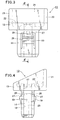
- Fig. 8 is a front elevation view of the pin in the clip shown in Fig. 2;
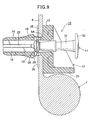
- Fig. 9 is a sectional view showing how a clip relating to an embodiment of the present invention is provisionally fixed to in a curtain-shield airbag;
- Fig. 10 is a sectional view showing how the clip-equipped curtain-shield airbag shown in Fig. 9 is provisionally fixed to a body panel; and
- Fig. 11 is a sectional view showing how, from a provisionally fixed condition, a curtain-shield airbag is permanently fixed to a body panel by the insertion of a pin.
-
- A first embodiment of the present invention will now described with reference to the drawings. Fig. 1 basically diagrams how a curtain-shield airbag 1 is attached in an automobile. The curtain-shield airbag 1, which is primarily for protecting the heads of occupants of the automobile, is attached to a
body panel 2 at the top of the door windows, from the front to the rear, on the inside of the automobile. At the time of a collision, for example, gas from a compressed gas source 3 (an inflator) is ejected, and the curtain-shield airbag very rapidly deploys toward the lower part of the door windows (in the direction of arrow 5) to protect the heads and other body portions of vehicle occupants. The curtain-shield airbag 1 comprises a main airbag unit andairbag attaching members 6. The airbag attaching members are secured to a body panel, such as a frame of the automobile, at a plurality of prescribed positions at the top of the door windows. The main airbag unit, at normal times, is folded small and housed at a fixed position at the top of the door windows. - Fig. 2 shows a
clip 10 relating to the first embodiment of the present invention. Thisclip 10 comprises two components, namely a rod-shaped pin 11 and abushing 13 for receiving thepin 11. Thebushing 13 comprises aleg 14 that is inserted into an attachment hole in an airbag attaching member and into an attachment hole in a body panel, and aflange 15 formed integrally with the leg, for holding the airbag attaching member in cooperation with the body panel. In theflange 15 and theleg 14, a bore is formed comprising aflange hole 17 and ashaft hole 18 continuing therefrom, into which thepin 11 can be inserted. On outer side surfaces of theleg 14, one or more resiliently mountedengagement pieces 19 are provided, protruding to the outside, and capable of engaging edge regions of an attachment hole in theairbag attaching member 6 and an attachment hole in thebody panel 2. The configuration is such that, when the pin I 1 is substantially fully inserted into thebore engagement pieces 19 are put in a permanently fixed condition, with the flexure thereof toward the inside of the shaft hole prevented. When thepin 11 is not deeply in thebore shaft hole 18. Thepin 11 and the bushing are coupled so that they can not be easily separated when in the provisionally fixed condition, as shown in Fig. 2. - At one edge of the
flange 15, apartition plate 21 stands perpendicularly from the flange edge, so as to provide a partition between the main airbag unit of the curtain-shield airbag 1 and the part of theflange 15 where the opening to thehole 17 is located. - Details of the
bushing 13 will now be described with reference to Figs. 2 to 7. Thebushing 13 is preferably an integral molding formed of hard plastic, comprising theleg 14 for insertion into both an attachment hole in theairbag attaching member 6 of the curtain-shield airbag 1 from an attachment hole in thebody panel 2, theflange 15 at one end (the upper end in Figs. 2, 3, 4, and 6) of theleg 14, for holding theairbag attaching member 6 in cooperation with thebody panel 2, and thepartition plate 21, standing perpendicularly from the flange edge, for partitioning the main airbag unit of the curtain-shield airbag 1 and the main part of theflange 15. In the central portion of theflange 15 and in the axial core of theleg 14 are formed theflange hole 17 and theshaft hole 18 continuing therefrom to allow insertion of thepin 11. - The
flange 15 is formed so that the surface on theleg 14 side (the lower surface in Figs. 2, 3, 4, and 6) is flat, so that the entirety thereof can abut the airbag attaching member, and so that the bushing holds the airbag attaching member in cooperation with the body panel. The opening to hole 17 at the opposite side from the leg 14 (the upper surface in Figs. 2, 3, 4, and 6) is tapered to facilitate reception of a pin. In the example shown, theflange 15 is formed as a substantially rectangular rigid plate-shaped body. A number ofconcavities 22 can be formed in this body, as shown in Fig. 5, to save on material and reduce the weight of the flange, while maintaining the rigidity thereof - At one edge of the flange rectangle, the
partition plate 21 stands perpendicularly from the flange, in the direction opposite to the direction in which theleg 14 extends, so as to form a partition between the main airbag unit of the curtain-shield airbag 1 and the opening to hole 17 of theflange 15. Thispartition plate 21 has a certain height and a width that extends across the length of the edge, so as to isolate the main airbag unit from the center part of theflange 15, and has a certain thickness that provides high rigidity. Because of thepartition plate 21, when thepin 11 is inserted, there is no extension of the main airbag unit to the center part of theflange 15 where the opening to hole 17 is located, so that any danger of the main airbag unit being drawn in by the pin is eliminated. Also, in the face of the reaction associated with the rapid deployment of the main airbag unit when the curtain-shield airbag is activated, the effects thereof toward theflange 15 can be diminished by thepartition plate 21. In the event of such deployment, the force with which the main airbag unit presses against thepartition plate 21 is great, so thepartition plate 21 is preferably supported bytriangular support ribs 23 formed at two other edges of theflange 15 to even more strongly preserve rigidity. - The
leg 14 is formed to a suitable length for attaching theairbag attaching member 6 to thebody panel 2. Theshaft hole 18 of theleg 14 can be formed to any appropriate length so long as thepin 11 can be properly inserted therein. The shaft hole passes completely through theleg 14 in the example shown, but the shaft hole may be terminated at some intermediate point in theleg 14. The cross-sectional shape of theleg 14 may be circular or rectangular or some other shape, but it should preferably be non-circular so that theleg 14 will not turn after attachment has been effected, in order that thepartition plate 21 can be set at a position facing the main airbag unit. In the example shown, the leg cross-section is a rectangular shape. Because of the rectangular cross-section of theleg 14, turning can be prevented afterleg 14 insertion, and it is easy for a worker, by visual inspection, to attach thebushing 13 to the airbag attaching member so that thepartition plate 21 faces the main airbag unit. The cross-section of theshaft hole 18 of theleg 14 can be any appropriate shape that will permit proper insertion of the pin. In this embodiment, the cross-section of theshaft hole 18 is rectangular, which matches the rectangular cross-section of the leg. On the inner wall of theshaft hole 18, a pair of guide ribs 25 (see Figs. 6, 7) is formed, to a certain thickness, protruding laterally inside, for guiding thepin 11 inserted into the shaft hole in alignment with the axial core of the shaft hole. - On side surfaces of the
leg 14, a pair of resiliently mountedengagement pieces 19 is deployed, protruding laterally to the outside. The engagement pieces can effect provisional fixing at the edges of the two attachment holes, i.e. the one in the airbag attaching member and the one in the body panel. Theengagement pieces 19 are configured so that, when thepin 11 is substantially fully inserted into thebore pin 11 is not so inserted, flexure to the inside is allowed. Each of theengagement pieces 19 is formed with theleg 14 end (lower end in Figs. 2, 3, 4, and 6) as its root and theflange 15 end as its free end. For that reason, as shown in Fig. 3, an invertedU-shaped slit 26 is formed about the periphery of eachengagement piece 19. This slit separates the engagement piece from the main body of theleg 14. - The lower end of the
engagement piece 19, where the engagement piece is attached to theleg 14, forms a hinge that imparts elasticity to the engagement piece so that the free end of the engagement piece can move inwardly and outwardly relative to theleg 14. On the outer surface of theengagement piece 19,shoulder 27 is formed for engaging edge regions of the attachment holes of both the airbag attaching member and the body panel. Theengagement piece 19 is formed so as to slope gently from theshoulder 27 toward the tip of the leg, so that the engagement piece does not become an impediment when theleg 14 is inserted into the attachment holes of both the airbag attaching member and the body panel. The position of theshoulder 27 is determined suitably to match the thickness of the airbag attaching member and the body panel. - On the inside of the
leg 14, one ormore pawls 29 are formed, extending elastically inside at positions adjacent to theflange 15. The pawls are useful for coupling thepin 11 to thebushing 13, while maintaining the provisionally fixed condition at which theengagement pieces 19 of thebushing 13 can flex to the inside of theshaft hole 18. - The
pin 11 will now be described with reference to Fig. 8 and Fig. 2. Thepin 11 is formed overall in a rod shape. A large-diameter head 30 of circular shape, for example, is formed at one end (the upper end in the figures) of ashaft 31 which forms the main body of the pin; and makes such operations as insertion into thebushing 13 easy. To enhance rigidity, theshaft 31 andhead 30 of thepin 11 are preferably solid (not hollow). On theshaft 31, a permanently fixingengagement part 33 is formed, at a position of intermediate height, for engaging thepawls 29, so as to maintain the permanently fixed condition when thepin 11 has been fully inserted in thebore shaft 31, in addition, a provisionally fixingengagement part 34 is formed. The tip portion (lower end in Fig. 2) of theshaft 31 stops at a position adjacent to theflange 15 of theshaft hole 18, for engaging thepawls 29 with theengagement part 34, so as to maintain the provisionally fixed condition. In Fig. 2, the pin and the bushing are coupled, so that they are not easily separated, by the provisionally fixingengagement part 34 engaging thepawls 29. Thereby, thepin 11 and thebushing 13 can be held together. In this provisionally fixed condition, moreover, theengagement pieces 19 are also in a provisionally fixed condition wherein they can flex to the inside of theshaft hole 18. - Provisional fixing of the
clip 10 to the airbag attaching member of the curtain-shield airbag can be accomplished easily by the simple operation of inserting theleg 14 of thebushing 13 into the attachment hole of the airbag attaching member. As shown in Fig. 8, the permanently fixingengagement part 33 is an engagement shoulder formed at a position between the tip (lower end) and thehead 30 of theshaft 31, and the provisionally fixingengagement part 34 is an engagement shoulder formed near the tip of theshaft 31. Portions of thepin 11 are tapered, as shown in Fig. 8, to facilitate insertion of the pin into the bore of thebushing 13. Theshaft 31, is preferably solid and of high rigidity, so that, in the permanently fixed condition wherein theshaft 31 of thepin 11 has been deeply inserted into theshaft hole 18 of theleg 14 of thebushing 13, the inner walls of the free ends of the engagement pieces 19 (the ends on theflange 15 side) facing the shaft hole are prevented from flexing to the inside. Thus, theclip 10 is attached to theairbag attaching member 6 and thebody panel 2 with high strength. - The operation of using the
clip 10 having the configuration described above to attach the curtain-shield airbag 1 to thebody panel 2 of an automobile will now be described with reference to Fig. 2 and Figs. 9 to 11. First, as shown in Fig. 2, with theshaft 31 of thepin 11 inserted both in thehole 17 of theflange 15 of thebushing 13 and in theshaft hole 18 of theleg 14, in the provisionally fixed condition wherein the provisionally fixingengagement part 34 is engaged with thepawls 29 at a provisionally fixing position, thepin 11 and thebushing 13 are coupled, so that theclip 10 is in a provisionally fixed coupled condition. Next, as shown in Fig. 9, theleg 14 of theclip 10 in the provisionally fixed coupled condition is inserted into theattachment hole 6A of theairbag attaching member 6 for the curtain-shield airbag 1, whereupon theclip 10 is pre-attached to the curtain-shield airbag 1. When that is the case, thepartition plate 21 will be positioned so as to face the main airbag unit of the curtain-shield airbag 1. Thepartition plate 21 effects a partition between the main airbag unit and theairbag attaching member 6, so that theleg 14 of thebushing 13 can easily be inserted into the attachment hole of theairbag attaching member 6. -
Clips 10 can be attached beforehand, respectively, in the attachment holes of a plurality of airbag attaching members 6 (see Fig. 1), thereby forming a clip-equipped curtain-shield airbag assembly. Merely by carrying this curtain-shield airbag assembly onto an automobile outfitting line or the like and inserting legs of the bushings through a body panel, the curtain-shield airbag can be provisionally fixed to the body panel, and the number of operations on the outfitting line can be reduced. Furthermore, when thelegs 14 are inserted into the attachment holes of theairbag attaching members 6, or after that insertion, asupport plate 35 for holding theairbag attaching members 6 in cooperation with theflanges 15 can be attached by inserting thelegs 14 through attachment holes in the support plate. Thesupport plate 35, as shown, is formed of thin plate material, and the attachment holes through which thelegs 14 pass are formed of such size as to engage the shoulders of theengagement pieces 19 with edge regions of the attachment holes, so that a provisionally fixed condition wherein theairbag attaching members 6 are flush against theflanges 15 is maintained. By selecting the thickness of thesupport plate 35, the total thickness of the attachment regions when the curtain-shield airbag 1 is attached to thebody panel 2 can also be suitably adjusted. - In Fig. 10, the
airbag attaching member 6 of the clip-equipped curtain-shield airbag 1 is coupled in a provisionally fixed condition to thebody panel 2, thereby forming an assembly that includes the body panel. For this coupling, eachattachment hole 2A is formed at a prescribed position (position of theairbag attaching members 6 in Fig. 1) in thebody panel 2. Thereupon, the tip of theleg 14 of eachbushing 13 on the curtain-shield airbag 1 to which theclip 10 is pre-attached is aligned with anattachment hole 2A. Next, merely by inserting thelegs 14 into the attachment holes 2A, theengagement pieces 19 will engage edge regions of the attachment holes 2A in thebody panel 2, and the airbag 1 will be attached to thebody panel 2 through theclip 10. This condition is the provisionally fixed condition. By having a plurality ofclips 10 attached, respectively, at prescribed positions on the curtain-shield airbag 1, and merely inserting thelegs 14 intoattachment holes 2A formed at corresponding positions (positions of theairbag attaching members 6 in Fig. 1) of thebody panel 2, the curtain-shield airbag 1 will be provisionally fixed at a prescribed position on thebody panel 2. - In Fig. 11, the
head 30 of a provisionally fixedpin 11 is inserted by hand, in the direction ofarrow 37, into thebushing 13 of eachclip 10, and theshaft 31 of thepin 11 is inserted deeply into the shaft hole of theleg 14. The tapered configuration of theshaft 31 facilitates insertion of the pin. At an edge of theflange 15, thepartition plate 21 effects a partition between the main airbag unit and the center of theflange 15, so that there is no danger of the main body of the airbag 1 being caught and tightened down when thepin 11 is inserted. Theshaft 31 of thepin 11, due to the strong pressing force toward thehead 30, is inserted deeply into theshaft hole 18, with the provisionally fixingengagement part 34 passing thepawls 29, and, when thehead 30 of thepin 11 is substantially flush against theflange 15, thepawls 29 engage the permanently fixingengagement part 33 of theshaft 31 at a permanently fixing position, whereupon a permanent fixing condition is effected. Because theshaft 31 is on the inside of theengagement pieces 19, the condition of theengagement pieces 19 is such that they protrude to the outside, with the flexure thereof to the inside prevented; the engagement shoulders 27 are engaged with thebody panel 2; and the permanent fixing condition is maintained. Accordingly, the curtain-shield airbag 1 is very strongly attached to thebody panel 2. Also, thepartition plate 21 can cope with the shock of the reaction accompanying the rapid deployment of the airbag when it is activated, and the effects thereof toward theflange 15 side can be diminished. - While preferred embodiments of the invention have been shown and described , it will be apparent that changes can be made without departing from the principles and spirit of the invention, the scope of which is defined in the following claims.
Claims (15)
- A clip for attaching an attaching member for a curtain-shield airbag to a body panel, comprising:a pin, and a bushing for receiving the pin, wherein:the bushing has a leg that is inserted into an attachment hole in the airbag attaching member and into an attachment hole in the body panel, and a flange integral with the leg for holding the airbag attaching member in cooperation with the body panel;the bushing has a bore through the flange and the leg into which the pin can be inserted;the leg has an external flexibly supported engagement piece capable of engaging edge regions of the hole in the airbag attaching member and the hole in the body panel;the engagement piece is configured so as to be in a permanently fixed condition with flexure thereof toward the inside of the bore prevented when the pin is inserted into the bore to a permanently fixing position, and so as to be in a provisionally fixed condition, with flexure toward the inside of the bore permitted, when the pin is not inserted into the bore to the permanently fixing position; anda partition plate is integrally formed at a flange edge, so as to stand from the flange edge to form a partition between the main airbag unit of the curtain-shield airbag and part of the flange at which there is an opening to the bore.
- The clip recited in claim 1, wherein a pawl extends elastically to the inside of the bore at a position adjacent to the flange, the pin has a permanently fixing engagement part for engaging the pawl so as to maintain the permanently fixed condition when the pin is inserted deeply into the bore, and the pin has a provisionally fixing engagement part for engaging the pawl so as to maintain the provisionally fixed condition when the pin is not inserted deeply into the bore.
- The clip recited in claim 2, wherein the pin comprises a shaft and a head integrally formed at one end of the shaft, the permanently fixing engagement part is a shoulder formed at a position between a tip of the shaft and the head, and the provisionally fixing engagement part is a shoulder formed near the tip of the shaft.
- The clip recited in claim 2, wherein when the shaft is inserted into an attachment hole in the airbag attaching member of the curtain-shield airbag, in a condition such that the pin and the bushing are coupled by the engagement of the provisionally fixing engagement part and the pawl, the entire clip is pre-attached to the curtain-shield air bag.
- The clip recited in claim 1, wherein there are a pair of the engagement pieces with one end attached flexibly to the leg and another end free, and the pin part inserted into the bore has the rigidity to prevent flexure of the free end of the engagement pieces toward the inside of the bore.
- A clip for attaching an attaching member for a curtain-shield airbag to a body panel, comprising:a bushing having a flange and a leg extending from the flange at one side thereof, the bushing having a bore extending through the flange and into the leg from an opening at an opposite side of the flange, the leg having an opening in a side wall thereof and having a protrusion from the side wall, flexibly mounted on the side wall at a root end of the protrusion remote from the flange, for movement into andout of the bore through the opening in the side wall, the protrusion tapering outwardly of the side wall from the root end to an opposite free end of the protrusion and having a shoulder at the free end for engaging an edge region of a hole in a panel through which the leg is inserted; anda pin constructed for insertion into the bore of the bushing to a permanently fixed position at which the pin is held in the bore and blocks movement of the protrusion into the bore.
- A clip according to claim 6, wherein the bushing and the pin have cooperable elements for holding the pin in the bushing at a provisionally fixed position at which the pin does not block movement of the protrusion into of the bore.
- A clip according to claim 7, wherein the cooperable elements include a provisionally fixing shoulder on the pin and a pawl in the bore.
- A clip according to claim 8, wherein the pin has a permanently fixing shoulder cooperable with the pawl for holding the pin at the permanently fixing position.
- A clip according to claim 9, wherein the pin has an outer surface portion that tapers from an end adjacent to the permanently fixing shoulder to a smaller end adjacent to the provisionally fixing shoulder.
- A clip according to claim 6, wherein the bushing has a partition projecting from an end of the flange in a direction opposite to a direction in which the leg extends from the flange.
- An assembly comprising the clip recited in Claim 6 and an attaching member for a curtain-shield airbag, with the flange of the bushing abutting the attaching member and the partition between a main airbag unit and the opening to the bore, the leg of the bushing extending through a hole in the attaching member, the shoulder of the protrusion adjacent to an edge region of the hole, and the pin inserted into the bore of the bushing to the provisionally fixing position.
- An assembly according to claim 12, further comprising a body panel having a hole through which the leg of the bushing is inserted after insertion into the hole of the attaching member, wherein the shoulder of the protrusion engages an edge region of the hole in the body panel.
- An assembly comprising the clip of claim 6, an attaching member for a curtain-shield airbag, and a body panel, with the flange of the bushing abutting the attaching member and the partition between a main airbag unit and the opening to the bore, the leg of the bushing extending through a hole in the attaching member and then through a hole in the body panel, the shoulder of the protrusion engaging an edge region of the hole in the body panel, and the pin inserted in the bore of the bushing to the permanently fixing position.
- A bushing for use in attaching an attaching member for a curtain-shield airbag to a body panel, wherein the bushing comprises:a flange and a leg extending from the flange at one side thereof, the bushing havinga bore extending through the flange and into the leg from an opening at an opposite side of the flange, the leg having an opening in a side wall thereof and having a protrusion from the side wall, flexibly mounted on the side wall at a root end of the protrusion remote from the flange, for movement into and out of the bore through the opening in the side wall, the protrusion tapering outwardly of the side wall from the root end to an opposite free end of the protrusion and having a shoulder at the free end for engaging an edge region of a hole in a panel through which the leg is inserted.
Applications Claiming Priority (2)
| Application Number | Priority Date | Filing Date | Title |
|---|---|---|---|
| JP2003204506A JP4152829B2 (en) | 2003-07-31 | 2003-07-31 | Curtain shield airbag clip |
| JP2003204506 | 2003-07-31 |
Publications (2)
| Publication Number | Publication Date |
|---|---|
| EP1502828A1 true EP1502828A1 (en) | 2005-02-02 |
| EP1502828B1 EP1502828B1 (en) | 2007-03-07 |
Family
ID=33535618
Family Applications (1)
| Application Number | Title | Priority Date | Filing Date |
|---|---|---|---|
| EP04018259A Active EP1502828B1 (en) | 2003-07-31 | 2004-08-02 | Curtain-shield airbag clip |
Country Status (6)
| Country | Link |
|---|---|
| US (1) | US7273227B2 (en) |
| EP (1) | EP1502828B1 (en) |
| JP (1) | JP4152829B2 (en) |
| CA (1) | CA2475983C (en) |
| DE (1) | DE602004005112T2 (en) |
| ES (1) | ES2281723T3 (en) |
Cited By (6)
| Publication number | Priority date | Publication date | Assignee | Title |
|---|---|---|---|---|
| WO2006005454A1 (en) * | 2004-07-08 | 2006-01-19 | Autoliv Development Ab | Airbag module |
| WO2006108889A1 (en) * | 2005-04-13 | 2006-10-19 | Dalphi Metal España, S.A. | Curtain airbag with means for attaching same to a vehicle |
| EP1721788A1 (en) * | 2005-04-22 | 2006-11-15 | Lisi Automotive Rapid | Fastening element for fastening and restraining an airbag on a vehicle body |
| WO2007073821A1 (en) | 2005-12-24 | 2007-07-05 | A. Raymond Et Cie | Device for fastening an attachment to a support part |
| WO2008025444A1 (en) * | 2006-08-31 | 2008-03-06 | Autoliv Development Ab | Curtain-type airbag module |
| EP2199628A1 (en) * | 2008-12-18 | 2010-06-23 | Newfrey LLC | Fastener |
Families Citing this family (38)
| Publication number | Priority date | Publication date | Assignee | Title |
|---|---|---|---|---|
| JP3961406B2 (en) * | 2002-11-19 | 2007-08-22 | ポップリベット・ファスナー株式会社 | Curtain airbag fixing tool |
| JP2006088985A (en) * | 2004-09-27 | 2006-04-06 | Toyoda Gosei Co Ltd | Head protection air-bag device |
| JP4535892B2 (en) * | 2005-01-25 | 2010-09-01 | ポップリベット・ファスナー株式会社 | clip |
| US20060197317A1 (en) * | 2005-03-07 | 2006-09-07 | Takata Corporation | Airbag attachment structure |
| JP2006336821A (en) * | 2005-06-06 | 2006-12-14 | Nippon Pop Rivets & Fasteners Ltd | Fixing tool with high fixing strength |
| US7832693B2 (en) | 2005-12-07 | 2010-11-16 | Illinois Tool Works Inc. | Fastener |
| US7698788B2 (en) * | 2006-03-27 | 2010-04-20 | Illinois Tool Works Inc. | Fastening clip with flexible tether |
| JP4870488B2 (en) * | 2006-07-13 | 2012-02-08 | ポップリベット・ファスナー株式会社 | High fixing strength fixture |
| DE202007002595U1 (en) * | 2007-02-22 | 2007-08-30 | Trw Automotive Electronics & Components Gmbh & Co. Kg | fastening device |
| KR200469406Y1 (en) * | 2007-05-09 | 2013-10-10 | 일리노이즈 툴 워크스 인코포레이티드 | Fastener clip and method of fabricating the same |
| DE102007032713B4 (en) * | 2007-07-13 | 2015-04-30 | GM Global Technology Operations LLC (n. d. Ges. d. Staates Delaware) | Method and fastening arrangement for fastening an airbag or airbag module to a motor vehicle structure |
| DE102008014043B4 (en) * | 2008-03-13 | 2017-10-19 | Volkswagen Ag | Wiper motor mounting device and method for attaching a wiper motor |
| US7837225B2 (en) * | 2008-05-14 | 2010-11-23 | Illinois Tool Works Inc. | Airbag fastener assembly |
| EP2282255A1 (en) * | 2008-05-30 | 2011-02-09 | Nissha Printing Co., Ltd. | Mounting structure and mounting method of protection panel having touch input function |
| DE102008039819B4 (en) * | 2008-08-22 | 2011-04-07 | Takata-Petri Ag | Clamping element and arrangement with a clamping element |
| JP4941436B2 (en) * | 2008-09-12 | 2012-05-30 | 株式会社ダイフク | Conveyor equipment |
| JP2010144900A (en) | 2008-12-22 | 2010-07-01 | Nippon Pop Rivets & Fasteners Ltd | Anchor |
| DE102009022322A1 (en) * | 2009-05-22 | 2010-11-25 | Daimler Ag | Method for fastening a retaining element of an airbag |
| DE102009023923B4 (en) | 2009-06-04 | 2016-02-11 | Autoliv Development Ab | Fixing clamp and gas bag unit |
| DE102009024983B4 (en) * | 2009-06-16 | 2013-09-05 | Trw Automotive Electronics & Components Gmbh | joint assembly |
| KR101024110B1 (en) | 2009-08-10 | 2011-03-22 | (주)에이패스 | Method for assembling wheel cover to steering wheel |
| JP5378251B2 (en) * | 2010-01-29 | 2013-12-25 | 大和化成工業株式会社 | clip |
| US8876151B2 (en) * | 2010-09-07 | 2014-11-04 | Toyota Jidosha Kabushiki Kaisha | Garnish mounting apparatus |
| US9022415B2 (en) * | 2011-01-11 | 2015-05-05 | Autoliv Development Ab | Cover for airbag device, and airbag device |
| KR101940700B1 (en) | 2011-08-29 | 2019-01-21 | 일리노이즈 툴 워크스 인코포레이티드 | Airbag tethering clip assembly |
| JP5668716B2 (en) | 2012-03-30 | 2015-02-12 | トヨタ自動車株式会社 | Mounting clip and curtain airbag mounting device |
| JP5849826B2 (en) * | 2012-03-30 | 2016-02-03 | トヨタ自動車株式会社 | Mounting clip and curtain airbag mounting device |
| JP5904466B2 (en) | 2012-07-30 | 2016-04-13 | ポップリベット・ファスナー株式会社 | Fixture |
| JP5817682B2 (en) * | 2012-08-24 | 2015-11-18 | トヨタ自動車株式会社 | Curtain airbag mounting clip and curtain airbag mounting apparatus |
| US8480120B1 (en) | 2012-12-21 | 2013-07-09 | Honda Motor Co., Ltd. | Tether clip |
| CN103318122A (en) * | 2013-06-03 | 2013-09-25 | 锦州锦恒汽车安全系统有限公司 | Curtain type air bag fixing device |
| DE202013006149U1 (en) * | 2013-07-05 | 2014-10-06 | GM Global Technology Operations LLC (n. d. Gesetzen des Staates Delaware) | Fastening device and motor vehicle with an air bag and the fastening device |
| JP6107629B2 (en) | 2013-12-06 | 2017-04-05 | 豊田合成株式会社 | Head protection airbag device |
| JP6281514B2 (en) | 2015-03-26 | 2018-02-21 | トヨタ自動車株式会社 | Mounting clip and attachment mounting structure using the same |
| JP6229687B2 (en) | 2015-03-26 | 2017-11-15 | トヨタ自動車株式会社 | Mounting clip and attachment mounting structure using the same |
| JP6597504B2 (en) * | 2016-07-13 | 2019-10-30 | 豊田合成株式会社 | Head protection airbag device |
| JP6832425B2 (en) * | 2017-06-19 | 2021-02-24 | 株式会社パイオラックス | Fastener |
| US20200086819A1 (en) * | 2018-09-18 | 2020-03-19 | GM Global Technology Operations LLC | Fastener for a roof rail air bag in a vehicle and a roof rail airbag assembly including the fastener |
Citations (6)
| Publication number | Priority date | Publication date | Assignee | Title |
|---|---|---|---|---|
| US6149183A (en) * | 1998-09-09 | 2000-11-21 | Breed Automotive Technology, Inc. | Snap-in air bag module, connector and method of attachment |
| EP1104724A2 (en) * | 1999-12-03 | 2001-06-06 | Delphi Technologies, Inc. | Mounting arrangement for an airbag module |
| US6431585B1 (en) * | 2000-10-05 | 2002-08-13 | Lear Corporation | Dual stage fastener |
| EP1264743A1 (en) * | 1996-09-24 | 2002-12-11 | Autoliv Asp, Inc. | A fastener stud for a snap-on mounting attachment |
| US20030042712A1 (en) * | 2001-08-29 | 2003-03-06 | David Henderson | Mounting assembly for inflatable curtain |
| EP1422112A1 (en) * | 2002-11-19 | 2004-05-26 | Newfrey LLC | Fastener for curtain airbag |
Family Cites Families (14)
| Publication number | Priority date | Publication date | Assignee | Title |
|---|---|---|---|---|
| US3756116A (en) | 1971-09-27 | 1973-09-04 | Fastway Fasteners | Plastic nut or grommet |
| US4403377A (en) * | 1979-12-18 | 1983-09-13 | Nifco Inc. | Fastening device |
| US4375342A (en) * | 1981-01-14 | 1983-03-01 | Phillips Plastic Corp. | Two-piece plastic fastener |
| JPS59141210A (en) | 1983-02-01 | 1984-08-13 | Fuji Photo Film Co Ltd | Vacuum deposition device |
| US4757664A (en) * | 1985-06-04 | 1988-07-19 | Screenex Wire Weaving Manufacturers (Proprietary) Limited | Wear resistant panel arrangement |
| JPH0413446Y2 (en) * | 1987-06-30 | 1992-03-30 | ||
| JPH01216109A (en) | 1988-02-19 | 1989-08-30 | Nifco Inc | Screw gromet |
| JPH0247414U (en) * | 1988-09-29 | 1990-03-30 | ||
| JP2002081423A (en) | 2000-09-07 | 2002-03-22 | Nippon Pop Rivets & Fasteners Ltd | Clip |
| US6553615B1 (en) * | 2000-09-21 | 2003-04-29 | Illinois Tool Works Inc. | Two-piece sliding grommet |
| JP2002104127A (en) | 2000-09-27 | 2002-04-10 | Nippon Plast Co Ltd | Fixing structure for air bag for protecting head part |
| US6533487B2 (en) * | 2001-03-01 | 2003-03-18 | Illinois Tool Works Inc. | Spring rod end clip engaging a range of panel thicknesses |
| JP4213381B2 (en) * | 2001-12-07 | 2009-01-21 | 株式会社パイオラックス | clip |
| JP2003222113A (en) * | 2002-01-29 | 2003-08-08 | Nippon Pop Rivets & Fasteners Ltd | Clip |
-
2003
- 2003-07-31 JP JP2003204506A patent/JP4152829B2/en not_active Expired - Lifetime
-
2004
- 2004-07-27 CA CA2475983A patent/CA2475983C/en active Active
- 2004-07-30 US US10/902,568 patent/US7273227B2/en active Active
- 2004-08-02 DE DE602004005112T patent/DE602004005112T2/en active Active
- 2004-08-02 EP EP04018259A patent/EP1502828B1/en active Active
- 2004-08-02 ES ES04018259T patent/ES2281723T3/en active Active
Patent Citations (6)
| Publication number | Priority date | Publication date | Assignee | Title |
|---|---|---|---|---|
| EP1264743A1 (en) * | 1996-09-24 | 2002-12-11 | Autoliv Asp, Inc. | A fastener stud for a snap-on mounting attachment |
| US6149183A (en) * | 1998-09-09 | 2000-11-21 | Breed Automotive Technology, Inc. | Snap-in air bag module, connector and method of attachment |
| EP1104724A2 (en) * | 1999-12-03 | 2001-06-06 | Delphi Technologies, Inc. | Mounting arrangement for an airbag module |
| US6431585B1 (en) * | 2000-10-05 | 2002-08-13 | Lear Corporation | Dual stage fastener |
| US20030042712A1 (en) * | 2001-08-29 | 2003-03-06 | David Henderson | Mounting assembly for inflatable curtain |
| EP1422112A1 (en) * | 2002-11-19 | 2004-05-26 | Newfrey LLC | Fastener for curtain airbag |
Cited By (8)
| Publication number | Priority date | Publication date | Assignee | Title |
|---|---|---|---|---|
| WO2006005454A1 (en) * | 2004-07-08 | 2006-01-19 | Autoliv Development Ab | Airbag module |
| US7694999B2 (en) | 2004-07-08 | 2010-04-13 | Autoliv Development Ab | Airbag module |
| WO2006108889A1 (en) * | 2005-04-13 | 2006-10-19 | Dalphi Metal España, S.A. | Curtain airbag with means for attaching same to a vehicle |
| EP1721788A1 (en) * | 2005-04-22 | 2006-11-15 | Lisi Automotive Rapid | Fastening element for fastening and restraining an airbag on a vehicle body |
| WO2007073821A1 (en) | 2005-12-24 | 2007-07-05 | A. Raymond Et Cie | Device for fastening an attachment to a support part |
| EP1969241B1 (en) * | 2005-12-24 | 2014-04-16 | A. Raymond Et Cie | Device for fastening an attachment to a support part |
| WO2008025444A1 (en) * | 2006-08-31 | 2008-03-06 | Autoliv Development Ab | Curtain-type airbag module |
| EP2199628A1 (en) * | 2008-12-18 | 2010-06-23 | Newfrey LLC | Fastener |
Also Published As
| Publication number | Publication date |
|---|---|
| CA2475983A1 (en) | 2005-01-31 |
| DE602004005112D1 (en) | 2007-04-19 |
| CA2475983C (en) | 2011-11-22 |
| EP1502828B1 (en) | 2007-03-07 |
| US20050062263A1 (en) | 2005-03-24 |
| JP2005047325A (en) | 2005-02-24 |
| ES2281723T3 (en) | 2007-10-01 |
| DE602004005112T2 (en) | 2007-11-15 |
| US7273227B2 (en) | 2007-09-25 |
| JP4152829B2 (en) | 2008-09-17 |
Similar Documents
| Publication | Publication Date | Title |
|---|---|---|
| US7273227B2 (en) | Curtain-shield airbag clip and assemblies using the clip | |
| JP4870488B2 (en) | High fixing strength fixture | |
| US7210886B2 (en) | Fastener for curtain airbag | |
| EP1155918B1 (en) | Molding fastening assembly | |
| US7338068B2 (en) | Garnish clip for curtain shield airbag | |
| US7290795B2 (en) | Garnish clip for curtain shield airbag | |
| AU2005201588B2 (en) | Fastener | |
| US6896288B2 (en) | Guide member for curtain airbag | |
| JP2006336821A (en) | Fixing tool with high fixing strength | |
| EP1653092A1 (en) | Vehicle mirror device assembly | |
| US5947630A (en) | Side air bag module attachment | |
| ATE252954T1 (en) | PULLING MANDLE COLLECTION ARRANGEMENT FOR A BLIND RIVET SETTING DEVICE | |
| JP5395029B2 (en) | Pull handle support structure | |
| KR20210066959A (en) | Fender insulation for vehicles | |
| KR101028027B1 (en) | Plastic fastner for vehicle | |
| WO2002093026A1 (en) | Mounting fastener and assembly for vehicle trim panel | |
| JP2001315561A (en) | Installing structure of housing type assist grip | |
| JP4592951B2 (en) | Roof molding equipment | |
| CN210554655U (en) | Split type side safety air curtain device and support assembly thereof | |
| KR100201905B1 (en) | Attaching apparatus | |
| KR200226412Y1 (en) | Crash panel fixing clip | |
| KR20080033610A (en) | Plastic fastner for vehicle | |
| KR20050104977A (en) | Trim bracket for automobile | |
| JPH10217888A (en) | Air bag module | |
| KR20040046615A (en) | Mounting structure of head lamp |
Legal Events
| Date | Code | Title | Description |
|---|---|---|---|
| PUAI | Public reference made under article 153(3) epc to a published international application that has entered the european phase |
Free format text: ORIGINAL CODE: 0009012 |
|
| AK | Designated contracting states |
Kind code of ref document: A1 Designated state(s): AT BE BG CH CY CZ DE DK EE ES FI FR GB GR HU IE IT LI LU MC NL PL PT RO SE SI SK TR |
|
| AX | Request for extension of the european patent |
Extension state: AL HR LT LV MK |
|
| 17P | Request for examination filed |
Effective date: 20050715 |
|
| AKX | Designation fees paid |
Designated state(s): DE ES FR GB IT |
|
| GRAP | Despatch of communication of intention to grant a patent |
Free format text: ORIGINAL CODE: EPIDOSNIGR1 |
|
| RTI1 | Title (correction) |
Free format text: CURTAIN-SHIELD AIRBAG CLIP |
|
| GRAS | Grant fee paid |
Free format text: ORIGINAL CODE: EPIDOSNIGR3 |
|
| GRAA | (expected) grant |
Free format text: ORIGINAL CODE: 0009210 |
|
| AK | Designated contracting states |
Kind code of ref document: B1 Designated state(s): DE ES FR GB IT |
|
| REG | Reference to a national code |
Ref country code: GB Ref legal event code: FG4D |
|
| REF | Corresponds to: |
Ref document number: 602004005112 Country of ref document: DE Date of ref document: 20070419 Kind code of ref document: P |
|
| REG | Reference to a national code |
Ref country code: ES Ref legal event code: FG2A Ref document number: 2281723 Country of ref document: ES Kind code of ref document: T3 |
|
| PLBE | No opposition filed within time limit |
Free format text: ORIGINAL CODE: 0009261 |
|
| STAA | Information on the status of an ep patent application or granted ep patent |
Free format text: STATUS: NO OPPOSITION FILED WITHIN TIME LIMIT |
|
| 26N | No opposition filed |
Effective date: 20071210 |
|
| PG25 | Lapsed in a contracting state [announced via postgrant information from national office to epo] |
Ref country code: IT Free format text: LAPSE BECAUSE OF FAILURE TO SUBMIT A TRANSLATION OF THE DESCRIPTION OR TO PAY THE FEE WITHIN THE PRESCRIBED TIME-LIMIT Effective date: 20070307 |
|
| PGFP | Annual fee paid to national office [announced via postgrant information from national office to epo] |
Ref country code: ES Payment date: 20090826 Year of fee payment: 6 |
|
| PGFP | Annual fee paid to national office [announced via postgrant information from national office to epo] |
Ref country code: DE Payment date: 20090827 Year of fee payment: 6 |
|
| REG | Reference to a national code |
Ref country code: DE Ref legal event code: R119 Ref document number: 602004005112 Country of ref document: DE Effective date: 20110301 |
|
| PG25 | Lapsed in a contracting state [announced via postgrant information from national office to epo] |
Ref country code: DE Free format text: LAPSE BECAUSE OF NON-PAYMENT OF DUE FEES Effective date: 20110301 |
|
| REG | Reference to a national code |
Ref country code: ES Ref legal event code: FD2A Effective date: 20111019 |
|
| PG25 | Lapsed in a contracting state [announced via postgrant information from national office to epo] |
Ref country code: ES Free format text: LAPSE BECAUSE OF NON-PAYMENT OF DUE FEES Effective date: 20100803 |
|
| REG | Reference to a national code |
Ref country code: FR Ref legal event code: PLFP Year of fee payment: 13 |
|
| REG | Reference to a national code |
Ref country code: FR Ref legal event code: PLFP Year of fee payment: 14 |
|
| REG | Reference to a national code |
Ref country code: FR Ref legal event code: PLFP Year of fee payment: 15 |
|
| PGFP | Annual fee paid to national office [announced via postgrant information from national office to epo] |
Ref country code: GB Payment date: 20230629 Year of fee payment: 20 |
|
| PGFP | Annual fee paid to national office [announced via postgrant information from national office to epo] |
Ref country code: FR Payment date: 20230703 Year of fee payment: 20 |