EP1503570A2 - Image forming apparatus as client of a distributed file system, image processing method, image processing program and recording medium - Google Patents
Image forming apparatus as client of a distributed file system, image processing method, image processing program and recording medium Download PDFInfo
- Publication number
- EP1503570A2 EP1503570A2 EP04254500A EP04254500A EP1503570A2 EP 1503570 A2 EP1503570 A2 EP 1503570A2 EP 04254500 A EP04254500 A EP 04254500A EP 04254500 A EP04254500 A EP 04254500A EP 1503570 A2 EP1503570 A2 EP 1503570A2
- Authority
- EP
- European Patent Office
- Prior art keywords
- image forming
- forming apparatus
- file system
- file
- information processing
- Prior art date
- Legal status (The legal status is an assumption and is not a legal conclusion. Google has not performed a legal analysis and makes no representation as to the accuracy of the status listed.)
- Ceased
Links
Images


Classifications
-
- H—ELECTRICITY
- H04—ELECTRIC COMMUNICATION TECHNIQUE
- H04N—PICTORIAL COMMUNICATION, e.g. TELEVISION
- H04N1/00—Scanning, transmission or reproduction of documents or the like, e.g. facsimile transmission; Details thereof
- H04N1/32—Circuits or arrangements for control or supervision between transmitter and receiver or between image input and image output device, e.g. between a still-image camera and its memory or between a still-image camera and a printer device
- H04N1/32101—Display, printing, storage or transmission of additional information, e.g. ID code, date and time or title
-
- G—PHYSICS
- G06—COMPUTING; CALCULATING OR COUNTING
- G06F—ELECTRIC DIGITAL DATA PROCESSING
- G06F3/00—Input arrangements for transferring data to be processed into a form capable of being handled by the computer; Output arrangements for transferring data from processing unit to output unit, e.g. interface arrangements
- G06F3/12—Digital output to print unit, e.g. line printer, chain printer
- G06F3/1293—Printer information exchange with computer
-
- G—PHYSICS
- G06—COMPUTING; CALCULATING OR COUNTING
- G06F—ELECTRIC DIGITAL DATA PROCESSING
- G06F3/00—Input arrangements for transferring data to be processed into a form capable of being handled by the computer; Output arrangements for transferring data from processing unit to output unit, e.g. interface arrangements
- G06F3/12—Digital output to print unit, e.g. line printer, chain printer
- G06F3/1296—Printer job scheduling or printer resource handling
-
- H—ELECTRICITY
- H04—ELECTRIC COMMUNICATION TECHNIQUE
- H04N—PICTORIAL COMMUNICATION, e.g. TELEVISION
- H04N1/00—Scanning, transmission or reproduction of documents or the like, e.g. facsimile transmission; Details thereof
- H04N1/00095—Systems or arrangements for the transmission of the picture signal
-
- H—ELECTRICITY
- H04—ELECTRIC COMMUNICATION TECHNIQUE
- H04N—PICTORIAL COMMUNICATION, e.g. TELEVISION
- H04N1/00—Scanning, transmission or reproduction of documents or the like, e.g. facsimile transmission; Details thereof
- H04N1/00127—Connection or combination of a still picture apparatus with another apparatus, e.g. for storage, processing or transmission of still picture signals or of information associated with a still picture
- H04N1/00204—Connection or combination of a still picture apparatus with another apparatus, e.g. for storage, processing or transmission of still picture signals or of information associated with a still picture with a digital computer or a digital computer system, e.g. an internet server
- H04N1/00209—Transmitting or receiving image data, e.g. facsimile data, via a computer, e.g. using e-mail, a computer network, the internet, I-fax
-
- H—ELECTRICITY
- H04—ELECTRIC COMMUNICATION TECHNIQUE
- H04N—PICTORIAL COMMUNICATION, e.g. TELEVISION
- H04N1/00—Scanning, transmission or reproduction of documents or the like, e.g. facsimile transmission; Details thereof
- H04N1/00127—Connection or combination of a still picture apparatus with another apparatus, e.g. for storage, processing or transmission of still picture signals or of information associated with a still picture
- H04N1/00204—Connection or combination of a still picture apparatus with another apparatus, e.g. for storage, processing or transmission of still picture signals or of information associated with a still picture with a digital computer or a digital computer system, e.g. an internet server
- H04N1/00244—Connection or combination of a still picture apparatus with another apparatus, e.g. for storage, processing or transmission of still picture signals or of information associated with a still picture with a digital computer or a digital computer system, e.g. an internet server with a server, e.g. an internet server
-
- H—ELECTRICITY
- H04—ELECTRIC COMMUNICATION TECHNIQUE
- H04N—PICTORIAL COMMUNICATION, e.g. TELEVISION
- H04N1/00—Scanning, transmission or reproduction of documents or the like, e.g. facsimile transmission; Details thereof
- H04N1/00912—Arrangements for controlling a still picture apparatus or components thereof not otherwise provided for
- H04N1/00938—Software related arrangements, e.g. loading applications
- H04N1/00944—Software related arrangements, e.g. loading applications using hot folders, i.e. folders or directories which trigger an action when written to or accessed
- H04N1/00946—Details of actions associated with a hot folder
-
- H—ELECTRICITY
- H04—ELECTRIC COMMUNICATION TECHNIQUE
- H04N—PICTORIAL COMMUNICATION, e.g. TELEVISION
- H04N1/00—Scanning, transmission or reproduction of documents or the like, e.g. facsimile transmission; Details thereof
- H04N1/00962—Input arrangements for operating instructions or parameters, e.g. updating internal software
- H04N1/00973—Input arrangements for operating instructions or parameters, e.g. updating internal software from a remote device, e.g. receiving via the internet instructions input to a computer terminal
-
- H—ELECTRICITY
- H04—ELECTRIC COMMUNICATION TECHNIQUE
- H04N—PICTORIAL COMMUNICATION, e.g. TELEVISION
- H04N1/00—Scanning, transmission or reproduction of documents or the like, e.g. facsimile transmission; Details thereof
- H04N1/21—Intermediate information storage
- H04N1/2166—Intermediate information storage for mass storage, e.g. in document filing systems
-
- H—ELECTRICITY
- H04—ELECTRIC COMMUNICATION TECHNIQUE
- H04N—PICTORIAL COMMUNICATION, e.g. TELEVISION
- H04N1/00—Scanning, transmission or reproduction of documents or the like, e.g. facsimile transmission; Details thereof
- H04N1/32—Circuits or arrangements for control or supervision between transmitter and receiver or between image input and image output device, e.g. between a still-image camera and its memory or between a still-image camera and a printer device
- H04N1/32358—Circuits or arrangements for control or supervision between transmitter and receiver or between image input and image output device, e.g. between a still-image camera and its memory or between a still-image camera and a printer device using picture signal storage, e.g. at transmitter
-
- H—ELECTRICITY
- H04—ELECTRIC COMMUNICATION TECHNIQUE
- H04N—PICTORIAL COMMUNICATION, e.g. TELEVISION
- H04N2201/00—Indexing scheme relating to scanning, transmission or reproduction of documents or the like, and to details thereof
- H04N2201/0008—Connection or combination of a still picture apparatus with another apparatus
- H04N2201/0034—Details of the connection, e.g. connector, interface
- H04N2201/0037—Topological details of the connection
- H04N2201/0039—Connection via a network
-
- H—ELECTRICITY
- H04—ELECTRIC COMMUNICATION TECHNIQUE
- H04N—PICTORIAL COMMUNICATION, e.g. TELEVISION
- H04N2201/00—Indexing scheme relating to scanning, transmission or reproduction of documents or the like, and to details thereof
- H04N2201/0008—Connection or combination of a still picture apparatus with another apparatus
- H04N2201/0034—Details of the connection, e.g. connector, interface
- H04N2201/0037—Topological details of the connection
- H04N2201/0043—Point to multipoint
-
- H—ELECTRICITY
- H04—ELECTRIC COMMUNICATION TECHNIQUE
- H04N—PICTORIAL COMMUNICATION, e.g. TELEVISION
- H04N2201/00—Indexing scheme relating to scanning, transmission or reproduction of documents or the like, and to details thereof
- H04N2201/0008—Connection or combination of a still picture apparatus with another apparatus
- H04N2201/0034—Details of the connection, e.g. connector, interface
- H04N2201/0046—Software interface details, e.g. interaction of operating systems
-
- H—ELECTRICITY
- H04—ELECTRIC COMMUNICATION TECHNIQUE
- H04N—PICTORIAL COMMUNICATION, e.g. TELEVISION
- H04N2201/00—Indexing scheme relating to scanning, transmission or reproduction of documents or the like, and to details thereof
- H04N2201/0077—Types of the still picture apparatus
- H04N2201/0094—Multifunctional device, i.e. a device capable of all of reading, reproducing, copying, facsimile transception, file transception
Definitions
- the present invention relates to an image forming apparatus such as copier / printer / scanner /facsimile / compound machine (to be also referred to as combined machine) and the like, an information processing method, an information processing program and a recording medium such as a CD-ROM.
- an image forming apparatus such as copier / printer / scanner /facsimile / compound machine (to be also referred to as combined machine) and the like, an information processing method, an information processing program and a recording medium such as a CD-ROM.
- the compound machine executes various information processing by using various programs such as applications or platforms.
- various storing means such as a hard disk drive and a memory card provided in the compound machine are used. If a hard disk drive or a memory card of a personal computer or a server computer that is connected to the compound machine can be used in addition to the hard disk drive or the memory card of the compound machine, more preferable execution environment can be realized for the information processing.
- the hard disk drive or the memory card of the compound machine can be used by a PC (personal computer) connected to the compound machine, more preferable execution environment can be realized for the information processing.
- an image forming apparatus that functions as a client of a distributed file system when the image forming apparatus is connected to a server apparatus that functions as a server of the distributed file system, the image forming apparatus including:
- the present invention is also configured as an information processing method performed in an image forming apparatus that functions as a client of a distributed file system when the image forming apparatus is connected to a server apparatus that functions as a server of the distributed file system, the information processing method including:
- the present invention is also configured as an information processing program for causing an image forming apparatus to perform information processing, wherein the image forming apparatus functions as a client of a distributed file system when the image forming apparatus is connected to a server apparatus that functions as a server of the distributed file system, the information processing program including:
- the object of the present invention is also achieved by an image forming apparatus that functions as a client of a distributed file system when the image forming apparatus is connected to a server apparatus that functions as a server of the distributed file system, the image forming apparatus including:
- the present invention can be configured as an information processing method performed in an image forming apparatus that functions as a client of a distributed file system when the image forming apparatus is connected to a server apparatus that functions as a server of the distributed file system, the information processing method including:
- the present invention can be configured as an information processing program for causing an image forming apparatus to perform information processing, wherein the image forming apparatus functions as a client of a distributed file system when the image forming apparatus is connected to a server apparatus that functions as a server of the distributed file system, the information processing program including:
- an image forming apparatus that functions as a server of a distributed file system, the image forming apparatus including:
- the present invention can be also configured as an information processing method performed in an image forming apparatus that functions as a server of a distributed file system, wherein the image forming apparatus includes a file system accessed as the distributed file system, wherein, when a file is stored in a file storing destination in the file system in which the file storing destination corresponds to a specific image forming process, the image forming apparatus performs the specific image forming process by using the file.
- the present invention can be also configured as an information processing program for causing an image forming apparatus to perform information processing, wherein the image forming apparatus functions as a server of a distributed file system and includes a file system that is accessed as the distributed file system, the information processing program including image forming process program code means, wherein, when a file is stored in a file storing destination in the file system in which the file storing destination corresponds to a specific image forming process, the image forming process program code means performs the specific image forming process by using the file.
- the present invention can be also configured as an image forming apparatus that functions as a server of a distributed file system, the image forming apparatus including:
- the present invention can be also configured as an image forming apparatus that functions as a server of a distributed file system, the image forming apparatus including:
- the image forming apparatus can use storage of apparatuses connected to the image forming apparatus as a destination for storing information used for information processing by the image forming apparatus so that environment for executing information processing can be improved.
- apparatuses connected to the image forming apparatus can use storage of the image forming apparatus so that environment for executing information processing can be improved.
- Fig.35 is a sequence diagram relating to a mail delivering process.
- Fig.1 shows a compound machine 101 of the embodiment of the present invention.
- the compound machine 101 shown in Fig.1 includes various hardware 111, various software 112 and a compound machine launching part 113.
- the hardware 111 of the compound machine 101 includes an image pickup part 121, a printing part 122, and other hardware 123.
- the image pickup part 121 is hardware for reading an image (image data) from a document.
- the printing part 122 is hardware for printing the image on a printing paper.
- the software 112 of the compound machine 101 includes various applications 131 and various platforms 132. These programs are executed in parallel as processes by an OS (operating system) such as UNIX.
- OS operating system
- the application 131 includes a copy application 141 that is an application for copying, a printer application 142 that is an application for printing, a scanner application 143 that is an application for scanning, a facsimile application 144 that is an application for facsimile, and a network file application 145 that is an application for network file.
- An application can be developed by using a dedicated SDK (software development kit).
- An application developed by using the SDK is called a SDK application.
- the SDK includes executable files of the platform 132, a dedicated function library of the platform 132, a C language standard function library, a compiler for compiling a source file of the application 131 to generate an object file of the application 131, and a linker for linking the object file with the dedicated function library and the standard function library to generate an executable file of the application.
- the compiler of the SDK includes an optional function (debug option) for adding a tag that is a detection code for debugging at an entry or at an exit of a function in a source code.
- a console PC 102 that is connected to the compound machine 101 displays a variable value, a function argument, or a function return value with a message. By displaying such information, the user can efficiently perform debugging of the SDK application.
- the platform 132 includes control services 151, a system resource manager 152, and handlers 153.
- the control services 151 include a network control service (NCS) 161, a facsimile control service (FCS) 162, a delivery control service (DCS) 163, an engine control service (ECS) 164, a memory control service (MCS) 165, an operation panel control service (OCS) 166, a certification control service (CCS) 167, a user directory control service (UCS) 168, and a system control service (SCS) 169.
- the handlers 153 include a facsimile control unit handler (FCUH) 171 and an image memory handler (IMH) 172.
- the process of the NCS 161 intermediates network communications.
- the process of FCS 162 provides APIs for facsimile.
- the process of DCS 163 controls delivery processes of stored documents.
- the process of ECS 164 performs control for the image pickup part 121 or the printing part 122.
- the process of MCS 165 performs control foe the memory and the hard disk drive.
- the process of the OCS 166 performs control of the operation panel.
- the process of CCS 167 performs control for authentication process and billing process.
- the process of the UCS 168 performs control relating to management of user information.
- the process of the SCS 169 performs control of management of the system.
- a virtual application service (VAS) 135 exists as software for performing mediation between the application 131 and the platform 132.
- the VAS 135 operates as a server process for each application that functions as a client, and operates as a client process for the platform that functions as a server.
- the VAS 135 has a wrapping function for hiding the platform 132 from the application 131.
- the VAS has a function for absorbing version differences between the platforms 132 and APIs of the applications.
- the compound machine launch part 113 is executed first when the power is turned on. Accordingly, the OS such as UNIX is launched, and the applications 131 and the platform 132 are launched. These programs are stored on the hard disk drive or in the memory card, and are read from the hard disk drive or from the memory card, and are loaded into a memory.
- Fig.2 is a hardware block diagram of the compound machine 101 shown in Fig.1.
- the hardware 111 of the compound machine 101 includes a controller 201, an operation panel 202, a facsimile control unit (FCU) 203, an image pickup part 121 and a printing part 122.
- FCU facsimile control unit
- the controller 201 includes a CPU 211, an ASIC 212, a NB 221, a SB 222, a MEM-P 231, a MEM-C 232, a HDD (hard disk drive) 233, a memory card slot 234, a NIC (network interface controller) 241, a USB device 242, an IEEE 1394 device 243 and a Centronics device 244.
- the CPU 211 is an IC for various information processing.
- the ASIC 212 is an IC for various image processing.
- the NB 221 is a north bridge for the controller 201.
- the SB 222 is a south bridge for the controller 201.
- the MEM-P 231 is a system memory for the compound machine 101.
- the MEM-C 232 is a local memory of the compound machine 101.
- the HDD 233 is a storage of the compound machine 101.
- the memory card slot 234 is a slot for setting the memory card 235.
- the NIC 241 is a controller for network communications by MAC addresses.
- the USB device 242 is a device for providing connection terminals of IEEE 1394 standard.
- the Centronics device 244 is a device for providing connection terminals of Centronics.
- the operation panel 202 is hardware (operation part) by which the user inputs data into the compound machine 101, and also hardware (display part) for obtaining output data from the compound machine 101.
- Fig.3 is an external view of the compound machine 101 of Fig.1.
- Fig.3 shows a position of the image pickup part 121, a position of the printing part 122 and a position of the operation panel 202.
- Fig.3 further shows a document setting part 301 on which the documents are set, a paper feed part 302 for feeding papers, and a paper ejecting part 303 for ejecting a printing paper.
- the operation panel 202 includes a touch panel 311, ten keys 312, a start button 313, a reset button 314, an initial setting button 315.
- the touch panel 311 is hardware (touch operation part) for inputting data by touch operation, and is also hardware (image display part) for displaying image.
- the ten keys 312 are hardware for input numbers by key operations.
- the start button 313 is hardware for performing start operation by button operation.
- the reset button 314 is hardware for performing reset operation by button operation.
- the initial setting button 315 is hardware for displaying an initial setting screen by button operation.
- the document setting part 301 includes an ADF (automatic document feeder) 321, a flat bed 322, and a flat bet cover 323.
- the paper feeding part 302 includes four feeding trays.
- the paper ejecting part 303 includes one ejecting tray.
- the compound machine launch part 113 includes a memory monitoring part 501 an a program launch part 502.
- BIOS and boot loader that form the memory monitoring part 501 are launched, so that the OS that is the UNIX is launched.
- a launch processing program that forms the program launch part 502 is launched, so that the applications and the platform 132 are launched.
- a kernel of the UNIX is launched, a root file system is unfolded, so that file systems relating to the applications and the platform are mounted on the root system file.
- the memory card slot 234 is a slot to which the memory card 235 is inserted, in which the memory card 235 stores programs such the applications 131 or the platform 132.
- the programs stored in the memory card 235 are read and loaded in the MEM-P 231 or the MEM-C 232.
- an SD (Secure Digital) memory card that is a kind of a flash memory card is used.
- SD memory card By using the SD memory card, there is a merit in that large capacity memories can be used at a low cost.
- a SD memory card slot is used as the memory card slot 234.
- the compound machine 101 includes a SD memory card access driver (SD access) 611, a SD memory card status driver (SD status) 612, a launch processing program 613, and a SD memory cad check program (SD check) 614 as software relating to the SD memory card slot 601 and the SD memory card 602 (corresponding to memory card slot 234 and memory card 235).
- SD access SD memory card access driver
- SD status SD memory card status driver
- SD check SD memory cad check program
- SD access 611 is a driver for performing access control for the SD memory card 602. More specifically, the SD access 611 detects insert/eject of the SD memory card 602, for example.
- SD status 612 is a driver for managing information of insert / eject /mount / unmount for the SD memory card.
- the launch processing program 613 is a program forming the program launch part 502 of Fig.5.
- the SD check 614 is a program for performing mount / unmount of the SD memory card 602.
- the SD access 611 detects that the SD memory card 602 is inserted in step 1, and SD access 611 notifies the SD status 612 of it in step 2.
- the SD status 612 manages information that indicates that the SD memory card 602 has been inserted, and notifies the launch processing program 613 that the SD memory card 602 has been inserted in step 3.
- the launch processing program 613 launches the SD check 614 to mount the SD memory card 602.
- the SD check 614 mounts the SD memory card 602 in step 5, and notifies the SD status 612 of it in step 6.
- the SD status 612 manages information indicating that the SD memory card 602 is mounted, and notifies the launch processing program 613 that the SD memory card 602 has been mounted in step 7.
- the SD access 611 detects that the SD memory card 602 has been pulled out in step 1, and SD access 611 notifies the SD status 612 that the SD memory card 602 has been pulled out in step 2.
- the SD status 612 manages information that indicates that the SD memory card 602 has been pulled out, and notifies the launch processing program 613 that that the SD memory card 602 has been pulled out in step 3.
- the launch processing program 613 launches the SD check 614 to unmount the SD memory card 602 in step 4.
- the SD check 614 unmounts the SD memory card 602 in step 5, and notifies the SD status 612 of it in step 6.
- the SD status 612 manages information indicating that the SD memory card 602 is unmounted, and notifies the launch processing program 613 that the SD memory card 602 has been unmounted in step 7.
- the information processing system shown in Fig.7 includes the compound machine 101 and a server computer 701.
- the compound machine 101 and the server computer 701 are connected by a LAN (local area network) 702.
- the LAN 702 is constituted by the Ethernet in this example.
- the compound machine 101 of Fig.1 performs various information processes by using various programs such as the applications 131 and the platforms 132.
- the information processing system of Fig.7 not only the HDD 233 and the SD memory card 602 of the compound machine 101 but also a HDD 703 and a SD memory card 705 of the server computer 701 can be used as a storing destination of information relating to various information processes performed by the compound machine 101.
- NFS network file system
- a file system in the HDD 703 in the server computer 701 can be used as a distributed file system of the compound machine 101.
- a file system of the server computer 701 is used as a storing destination of information relating to information processing by the compound machine 101.
- UNIX that is the OS 706 is installed in the HDD 703 of the server computer 701.
- the server computer 701 functions as a server (NFS server) of NFS.
- the OS (UNIX) is also installed in the HDD 233 in the compound machine 101.
- the compound machine 101 is connected to the server computer 701 via the network, so that the compound machine 101 functions as a client (NSF client) of NFS. Accordingly, information processing of NFS such as "vfs (virtual file system) operation", “v-node(virtual node) operation” can be performed by the UNIX in the server 701 and in the compound machine 101.
- Network protocols used for network communications in NFS between the compound machine 101 and the server computer 701 are IP as a network (third) layer protocol in the OSI reference model, UDP as a transport (fourth) layer protocol, RPC as a session (fifth) layer protocol, and XDR as a presentation (sixth) layer protocol.
- TCP may be used as the transport (fourth) layer protocol
- UDP is used in this embodiment in consideration of speed rather than reliability.
- samba may be used instead of NFS.
- Windows is installed in the HDD 703 in the server computer 701 as the OS 706, so that the server computer 701 functions as a server (samba server) of samba.
- UNIX is installed in the HDD 233 of the compound machine 101, and the compound machine 101 functions as a client (samba client) of samba.
- the UNIX machine can use a shared folder of a Windows machine.
- Network protocols for performing network communications in samba between the compound machine 101 and the server computer 701 are IP as the third layer, TCP as the fourth layer, NETBIOS as the fifth layer, SMB as the sixth layer, and samba as the seventh layer.
- NetBEUI can be used as the third and fourth layers
- NETBIOS can be used as the fifth layer.
- IPX can be used as the third layer
- SPX can be used as the fourth and fifth layers. Since SMB supports the folder sharing function and the file sharing function of Windows, the samba server can be called as a SMB server and the samba client can be called as a SMB client.
- NFS is used in the following example for the sake of explanation.
- the application in the compound machine 101 accesses a file in the file system of the server computer 701
- the application issues a mount system call for the file system of the server computer 701 in step 801.
- the OS 136 of the compound machine 101 mounts the file system of the server computer 701 on the compound machine 101 in step 802, so that the file system of the server computer 701 is accessible as a distributed file system of the compound machine 101.
- the application of the compound machine 101 accesses the file system as the distributed file system of the compound machine 101 so as to access the file.
- the application When the application starts to access the file, the application issues an open system call to the file in step 803. When the application ends to access the file, the application issues a close system call to the file in step 806. By performing the open system call, the application obtains a file descriptor of the file and the OS 136 obtains a file handle of the file.
- the application When the application accesses the file, the application issues a system call by using the file descriptor in step 804.
- the OS 136 of the compound machine 101 sends a system call of the file descriptor (that is a NFS call of the file handle) to the OS 706 of the server computer 701 in step 805.
- the OS 706 of the server computer 701 receives the NFS call, the OS 706 executes a command in the NFS call.
- Fig.9 is an example of information on the file system of the compound machine 101 that is displayed by a df command of the OS 136 (UNIX).
- Fig.9 shows that "a” in the HDD 233 is mounted on “/”, “e” is mounted on “/user”.
- Fig.9 shows that "/dir1” that is a directory (file system) of the server computer 701 "host_a” is mounted on “/host_a/dir1" that is a directory (mount point) of the compound machine 101.
- mount process is performed for mounting the file system of the server computer 701 on the compound machine 101 and the unmount process is performed for unmounting the file system of the computer 701 from the compound machine 101.
- steps 801 and 802 in Fig.8 when the application needs to access the file system, in response to the system call by the application, the OS 136 performs mount of the file system.
- the OS 136 when the application does not need to access the file system, in response to the system call by the application, the OS 136 performs unmount of the file system. According to necessity for accessing the file system of the server computer 701, mount or unmount for the file system of the server computer 701 is performed. The possibility that the compound machine 101 may be affected due to a trouble of the server computer 701 can be reduced by unmounting the file system from the server computer 701 when it is not necessary to access the file system of the server computer 701.
- automount of the OS 136 can be used.
- the file system may continue to be mounted on the compound machine 101 while the compound machine 101 is being operated.
- a setting file relating to the mount processing is prepared in the HDD 233 or in the SD memory card 602, so that the OS 136 executes the mount of the system file in response to a system call by the launch processing program at the time when the power of the compound machine 101 is turned on.
- NFS network file system
- the "ON mode” includes a “power saving mode” in addition to a normal “waiting mode", wherein the power saving mode is a mode for saving consumed power while the compound machine is waiting for image forming process.
- the power saving mode power sources that usually consume large power in a waiting status reduce power consumption, wherein the power sources that usually consume large power include a heater power source of a phaser of the printing part 122, a motor power source of a spindle of the HDD 233, a panel power source of the touch panel 311 and the like.
- Power sources that consume small power such as a power source of NIC 241 remains in the usual waiting mode. Accordingly, the viewpoint of convenience and the viewpoint of the power saving become compatible.
- the mode changes to the power saving mode.
- the mode changes to the OFF mode.
- the OFF mode when the compound machine 101 receives facsimile image data or scanned data of print data, the mode changes to the power saving mode.
- the power mode is changed from ON mode (waiting mode or power saving mode) to OFF mode.
- the power source mode is changed from OFF mode to ON mode (waiting mode).
- Fig.21 is a sequence diagram showing a transition process from the waiting mode to the power saving mode.
- a request of transition to the power saving mode is sent from the SCS 169 to the MCS 165 and to the application 131 in step 712. Then, a response of transition to the power saving mode is sent from the MCS 165 and from the application 131 to the SCS 169 in step 713.
- a decision notification of transition to the power saving mode is sent from the SCS 169 to the MCS 165 and the application 131 in step 714.
- a decision notification of transition to the power saving mode of the power source of the HDD 233 is sent from the MCS 165 to the application 131 in step 715.
- a decision notification of transition to the waiting mode is sent from the SCS 169 to the MCS 165 and to the application 131 in step 722.
- a decision notification of transition to a waiting mode in the power source of the HDD 233 is sent from the MCS 165 to the application 131 in step 723.
- Fig.22 is a sequence diagram of a transition process from the power saving mode to the OFF mode.
- a request of transition to the OFF mode is sent from the SCS 169 to the MCS 165 and the application 131 in step 732.
- a response of transition to the OFF mode is sent from the MCS 165 and the application 131 to the SCS 169 in step 733.
- a decision notification of transition to the OFF mode is sent from the SCS 169 to the MCS 165 and the application 131 in step 734.
- a decision notification of transition to the OFF mode of the power source of the HDD 233 is sent from the MCS 165 to the application 131 in step 735.
- the facsimile image data is sent from the FCS 162 to the MCS 165 by which the facsimile image data is stored in step 742. Then, a notification of storing the facsimile image data is sent from the MCS 165 to the application 131 in step 743. Next, a notification of storing the facsimile image data is sent from the application 131 to the SCS 169 in step 744, and a decision notification of transition to the power saving mode is sent from the SCS 169 to the MCS 165 and the application 131 in step 745. Next, a decision notification of transition to the power saving state of the power source of the HDD 233 is sent from the MCS 165 to the application 131 in step 746.
- the HDD 703 in the server computer 701 is used as a storing destination of a SDK application, so that the SDK application stored in the HDD 703 is loaded into the compound machine 101 and is launched in the compound machine 101.
- the SDK application can be launched in either of the waiting mode or in the power saving mode.
- the debugging of the SDK application is not interrupted.
- Fig.23 is a flowchart of a launching process of the SDK application in the HDD 233.
- the compound machine 101 For launching the SDK application stored in the HDD 233 in step 811, the compound machine 101 loads an execution portion of the SDK application into the VM (virtual memory) in step 812.
- the compound machine 101 checks if a necessary portion of the SDK application is loaded in the VM.
- the compound machine tries to access the HDD 233 to load the necessary portion of the SDK application into the VM in step 816.
- the HDD 233 since the HDD 233 is in the power saving status, the HDD 233 cannot be accessed so that the necessary portion of the SDK application cannot be restored in the VM. As a result, the SDK application enters a sleep status in step 817.
- the SDK application or a daemon may be loaded and executed in a RAM or a ROM.
- this method has a problem in that the capacity of the RAM or a ROM may become insufficient.
- Fig.24 shows a flowchart of a launching process of a SDK application in the HDD 703.
- the compound machine 101 loads an execution portion of the SDK application in the VM in step 822.
- the mode becomes the power saving mode while the SDK application is in an idle state (steps 823, 824)
- the compound machine 101 checks if a necessary portion of the SDK application is loaded in the VM.
- the compound machine tries to access the HDD 703 to load the necessary portion of the SDK application into the VM in step 826.
- the MCS 165 is an example of the information processing program of the present invention
- a SD memory card storing the MCS 165 is an example of the recording medium of the present invention.
- the compound machine 101 is an example of the image forming apparatus of the present invention and the information processing performed in the compound machine 101 is an example of the information processing method of the present invention.
- the second embodiment is different from the first embodiment in that the compound machine 101 functions as a server of NFS in the second embodiment.
- the information processing system shown in Fig.25 includes the compound machine 101 and a PC (personal computer) 1701.
- the compound machine 101 and the PC 1701 are connected by a LAN (local area network) 1702.
- the LAN 1702 is constituted by the Ethernet in this example.
- the compound machine 101 of Fig.1 performs various information processes by using various programs such as applications 131 and platforms 132.
- the compound machine includes storing devices such as the HDD 233 and the SD memory card 602.
- the information processing system of Fig.25 not only the compound machine 101 but also the PC 1701 can use the HDD 233 and the SD memory card 602 in the compound machine 101.
- NFS network file system
- a file system in the HDD 203 in the compound machine 101 can be used as a distributed file system of the PC 1701.
- a file system of the compound machine 101 is used as a storing destination of information relating to information processing of the PC 1701.
- UNIX as the OS 136 is installed in the HDD 223 of the compound machine 101.
- the compound machine 101 functions as a server (NFS server) of the distributed file system of NFS.
- the OS (UNIX) is also installed in the HDD 1703 in the PC 1701.
- the PC 1701 is connected to the compound machine 101 via the network, so that the PC 1701 functions as a client (NSF client) of NFS. Accordingly, information processing of NFS such as "vfs (virtual file system) operation", “v-node(virtual node) operation” can be performed by UNIX.
- Network protocols used for network communications for NFS between the compound machine 101 and the PC 1701 are IP as a network (third) layer protocol in OSI reference model, UDP as a transport (fourth) layer protocol, RPC as a session (fifth) layer protocol, and XDR as a presentation (sixth) layer protocol.
- IP IP
- UDP transport (fourth) layer protocol
- RPC session (fifth) layer protocol
- XDR presentation (sixth) layer protocol
- TCP may be used as the transport (fourth) layer protocol
- UDP is used in this embodiment in consideration of speed rather than reliability.
- samba may be used instead of NFS.
- UNIX is installed in the HDD 233 of the compound machine 101 so that the compound machine 101 functions as a server (samba server) of the distributed file system of samba.
- Windows is installed in the HDD 1703 in the PC 1701 as the OS 1706, so that the PC 1701 functions as a client (samba client) in samba.
- the Windows machine can use shared folders in a UNIX machine.
- Network protocols for performing network communications for samba between the compound machine 101 and the PC 1701 are IP as the third layer, TCP as the fourth layer, NETBIOS as the fifth layer, SMB as the sixth layer, and samba as the seventh layer.
- NetBEUI can be used as the third and fourth layers
- NETBIOS can be used as the fifth layer.
- IPX can be used as the third layer
- SPX can be used as the fourth and fifth layers. Since SMB supports the folder sharing function and the file sharing function of Windows, the samba server can be called as a SMB server and the samba client can be called a SMB client.
- NFS is used in the following example.
- FIG.26 an example of information processing performed by the PC 1701 in the case where an application 1708 in the PC 1701 accesses a file in the file system of the compound machine 101 is described.
- the application 1708 in the PC 1701 accesses a file in a file system of the compound machine 101
- the application issues a mount system call for the file system of the compound machine 101 in step 1801.
- the OS 1706 of the PC 1701 mounts the file system of the compound machine 101 on the PC 1701 in step 1802, so that the file system of the compound machine 101 is accessible as a distributed file system of the PC 1701.
- the application 1708 of the PC 1701 accesses the file system as the distributed file system of the PC 1701 so as to access the file.
- the application 1708 of the PC 1701 When the application 1708 of the PC 1701 starts to access the file, the application issues an open system call to the file in step 1803. When the application ends to access the file, the application issues a close system call to the file in step 1806. By performing the open system call, the application 1708 of the PC 1701 obtains a file descriptor of the file and the OS 1706 of the PC 1701 obtains a file handle of the file.
- the application 1708 of the PC 1701 accesses the file
- the application 1708 performs a system call by using the file descriptor in step 1804.
- the OS 1706 of the PC 1701 sends a system call of the file descriptor as a NFS call of the file handle to the OS 136 of the compound machine 101 in step 1805.
- the OS 136 of the compound machine 101 receives the NFS call
- the OS 136 executes a command of the NFS call.
- Fig.27 is an example of information on the file system of the PC 1701 that is displayed by a df command of the OS 1706 (UNIX).
- Fig.27 shows that "a” in the HDD 1703 is mounted on “/”, “e” is mounted on “/user”.
- Fig.27 shows that "/dir1” that is a directory (file system) of the compound machine 101 "host_a” is mounted on “/host_a/dir1" that is a directory (mount point) of the PC 1701.
- NFS network file system
Abstract
Description
- The present invention relates to an image forming apparatus such as copier / printer / scanner /facsimile / compound machine (to be also referred to as combined machine) and the like, an information processing method, an information processing program and a recording medium such as a CD-ROM.
- In recent years, a compound machine that includes a copying function, a printer function and a scanner function is coming onto the market. When the compound machine functions as a copier or a printer, an image is to be printed on a printing paper. When the compound machine functions as a copier or a scanner, an image is read from a document. When the compound machine functions as a facsimile, the compound machine receives or sends an image via a telephone line. Japanese laid-open patent application No.2002-84383 discloses a technology relating to the compound machine.
- The compound machine executes various information processing by using various programs such as applications or platforms. For storing information relating to the information processing, various storing means such as a hard disk drive and a memory card provided in the compound machine are used. If a hard disk drive or a memory card of a personal computer or a server computer that is connected to the compound machine can be used in addition to the hard disk drive or the memory card of the compound machine, more preferable execution environment can be realized for the information processing.
- In addition, if the hard disk drive or the memory card of the compound machine can be used by a PC (personal computer) connected to the compound machine, more preferable execution environment can be realized for the information processing.
- An object of the present invention is to enable the image forming apparatus to use storage of apparatuses connected to the image forming apparatus as a destination for storing information used for information processing by the image forming apparatus so as to improve environment for executing information processing. Another object of the present invention is to enable apparatuses connected to the image forming apparatus to use storage of the image forming apparatus so as to improve environment for executing information processing.
- The object is achieved by an image forming apparatus that functions as a client of a distributed file system when the image forming apparatus is connected to a server apparatus that functions as a server of the distributed file system, the image forming apparatus including:
- a distributed file system process part for mounting a file system of the server apparatus on the image forming apparatus to enable the image forming apparatus to access the file system of the server apparatus as the distributed file system of the image forming apparatus; and
- a storing process part for accessing the file system of the server apparatus and storing, in the file system, information that is stored in a storage unit used by the image forming apparatus.
-
- The present invention is also configured as an information processing method performed in an image forming apparatus that functions as a client of a distributed file system when the image forming apparatus is connected to a server apparatus that functions as a server of the distributed file system, the information processing method including:
- a storing process step of accessing a file system of the server apparatus as the distributed file system of the image forming apparatus, and storing, in the file system, information that is stored in a storage unit used by the image forming apparatus.
-
- In addition, the present invention is also configured as an information processing program for causing an image forming apparatus to perform information processing, wherein the image forming apparatus functions as a client of a distributed file system when the image forming apparatus is connected to a server apparatus that functions as a server of the distributed file system, the information processing program including:
- storing process program code means for accessing a file system of the server apparatus as the distributed file system of the image forming apparatus, and storing, in the file system, information that is stored in a storage unit used by the image forming apparatus.
-
- The object of the present invention is also achieved by an image forming apparatus that functions as a client of a distributed file system when the image forming apparatus is connected to a server apparatus that functions as a server of the distributed file system, the image forming apparatus including:
- a distributed file system process part for mounting a file system of the server apparatus on the image forming apparatus to enable the image forming apparatus to access the file system of the server apparatus as the distributed file system of the image forming apparatus; and
- a program launching part for accessing the file system of the server apparatus and launching, in the image forming apparatus, a program stored in the file system.
-
- The present invention can be configured as an information processing method performed in an image forming apparatus that functions as a client of a distributed file system when the image forming apparatus is connected to a server apparatus that functions as a server of the distributed file system, the information processing method including:
- a program launching step of accessing a file system of the server apparatus as the distributed file system of the image forming apparatus and launching, in the image forming apparatus, a program stored in the file system.
-
- In addition, the present invention can be configured as an information processing program for causing an image forming apparatus to perform information processing, wherein the image forming apparatus functions as a client of a distributed file system when the image forming apparatus is connected to a server apparatus that functions as a server of the distributed file system, the information processing program including:
- program launching program code means for accessing a file system of the server apparatus as the distributed file system of the image forming apparatus and launching, in the image forming apparatus, a program stored in the file system.
-
- The object is also achieved by an image forming apparatus that functions as a server of a distributed file system, the image forming apparatus including:
- a file system that is accessed as the distributed file system; and
- an image forming process part, wherein, when a file is stored in a file storing destination in the file system in which the file storing destination corresponds to a specific image forming process, the image forming process part performs the specific image forming process by using the file.
-
- The present invention can be also configured as an information processing method performed in an image forming apparatus that functions as a server of a distributed file system, wherein the image forming apparatus includes a file system accessed as the distributed file system,
wherein, when a file is stored in a file storing destination in the file system in which the file storing destination corresponds to a specific image forming process, the image forming apparatus performs the specific image forming process by using the file. - The present invention can be also configured as an information processing program for causing an image forming apparatus to perform information processing, wherein the image forming apparatus functions as a server of a distributed file system and includes a file system that is accessed as the distributed file system, the information processing program including image forming process program code means,
wherein, when a file is stored in a file storing destination in the file system in which the file storing destination corresponds to a specific image forming process, the image forming process program code means performs the specific image forming process by using the file. - The present invention can be also configured as an image forming apparatus that functions as a server of a distributed file system, the image forming apparatus including:
- a file system that is accessed as the distributed file system; and
- an image forming process part, wherein, when a file is stored in a file storing destination in the file system in which the file storing destination corresponds to a specific image forming process, the image forming process part causes another image forming apparatus to perform the specific image forming process by using the file.
-
- The present invention can be also configured as an image forming apparatus that functions as a server of a distributed file system, the image forming apparatus including:
- a file system that is accessed as the distributed file system; and
- a communication process part, wherein, when a file is stored in a file storing destination in file system in which the file storing destination corresponds to a specific communication process, the communication process part performs the specific communication process by using the file.
-
- According to the present invention, the image forming apparatus can use storage of apparatuses connected to the image forming apparatus as a destination for storing information used for information processing by the image forming apparatus so that environment for executing information processing can be improved. In addition, apparatuses connected to the image forming apparatus can use storage of the image forming apparatus so that environment for executing information processing can be improved.
- The invention will now be described purely by way of example and with reference to the figures, in which:
- Fig.1 shows a compound machine of an embodiment of the present invention;
- Fig.2 is a hardware block diagram of the compound machine of Fig.1;
- Fig.3 is an external view of the compound machine of Fig.1;
- Fig.4 shows an operation panel;
- Fig.5 shows a compound machine launching part;
- Fig.6 shows a configuration of software relating to a SD memory card slot and a SD memory card;
- Fig.7 shows an information processing system using NFS;
- Fig.8 is a flowchart for explaining information processing in NFS;
- Fig.9 shows an example of an output by df command;
- Fig.10 is a figure for explaining a first example of usage of NFS;
- Fig.11 is a figure for explaining a second example of usage of NFS;
- Fig.12 is a figure for explaining a third example of usage of NFS;
- Fig.13 is a figure for explaining a fourth example of usage of NFS;
- Figs.14A and 14B are figures for explaining formats of data stored in a HDD;
- Fig.15 is a sequence diagram relating to a copy process (scanning process);
- Fig.16 is a sequence diagram relating to a copy process (print process);
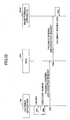
- Fig.17 is a sequence diagram relating to a facsimile sending process;
- Fig.18 is a sequence diagram relating to a facsimile receiving process;
- Fig.19 is a sequence diagram relating to a printing process;
- Fig.20 is a sequence diagram of an authentication process and a use restriction process;
- Fig.21 is a sequence diagram showing a transition process from a waiting mode to a power saving mode;
- Fig.22 is a sequence diagram of a transition process from a power saving mode to an OFF mode;
- Fig.23 is a flowchart of a launching process
of a SDK application in the
HDD 233; - Fig.24 shows a flowchart of a launching
process of a SDK application in the
HDD 703; - Fig.25 shows an information processing system using NFS;
- Fig.26 is a flowchart for explaining an example for explaining an information processing using NFS;
- Fig.27 is an example of an output by df command;
- Fig.28 is a figure for explaining examples of usage of NFS;
- Fig.29 shows a sequence diagram relating to a print process;
- Fig.30 is a sequence diagram relating to a facsimile sending process;
- Fig.31 is a sequence diagram relating to a print process;
- Fig.32 is a sequence diagram relating to a facsimile sending process;
- Fig.33 is a sequence diagram relating to a file transfer process;
- Fig.34 is a sequence diagram relating to a file update process;
-
- Fig.35 is a sequence diagram relating to a mail delivering process.
- In the following, the first embodiment of the present invention is described with reference to figures.
- Fig.1 shows a
compound machine 101 of the embodiment of the present invention. Thecompound machine 101 shown in Fig.1 includesvarious hardware 111,various software 112 and a compoundmachine launching part 113. - The
hardware 111 of thecompound machine 101 includes animage pickup part 121, aprinting part 122, andother hardware 123. Theimage pickup part 121 is hardware for reading an image (image data) from a document. Theprinting part 122 is hardware for printing the image on a printing paper. - The
software 112 of thecompound machine 101 includesvarious applications 131 andvarious platforms 132. These programs are executed in parallel as processes by an OS (operating system) such as UNIX. - The
application 131 includes acopy application 141 that is an application for copying, aprinter application 142 that is an application for printing, ascanner application 143 that is an application for scanning, afacsimile application 144 that is an application for facsimile, and anetwork file application 145 that is an application for network file. - An application can be developed by using a dedicated SDK (software development kit). An application developed by using the SDK is called a SDK application. The SDK includes executable files of the
platform 132, a dedicated function library of theplatform 132, a C language standard function library, a compiler for compiling a source file of theapplication 131 to generate an object file of theapplication 131, and a linker for linking the object file with the dedicated function library and the standard function library to generate an executable file of the application. The compiler of the SDK includes an optional function (debug option) for adding a tag that is a detection code for debugging at an entry or at an exit of a function in a source code. When a SDK application to which the tag is added is launched in thecompound machine 101, aconsole PC 102 that is connected to thecompound machine 101 displays a variable value, a function argument, or a function return value with a message. By displaying such information, the user can efficiently perform debugging of the SDK application. - The
platform 132 includescontrol services 151, asystem resource manager 152, andhandlers 153. Thecontrol services 151 include a network control service (NCS) 161, a facsimile control service (FCS) 162, a delivery control service (DCS) 163, an engine control service (ECS) 164, a memory control service (MCS) 165, an operation panel control service (OCS) 166, a certification control service (CCS) 167, a user directory control service (UCS) 168, and a system control service (SCS) 169. Thehandlers 153 include a facsimile control unit handler (FCUH) 171 and an image memory handler (IMH) 172. - The process of the
NCS 161 intermediates network communications. The process ofFCS 162 provides APIs for facsimile. The process ofDCS 163 controls delivery processes of stored documents. The process ofECS 164 performs control for theimage pickup part 121 or theprinting part 122. The process ofMCS 165 performs control foe the memory and the hard disk drive. The process of theOCS 166 performs control of the operation panel. The process ofCCS 167 performs control for authentication process and billing process. The process of theUCS 168 performs control relating to management of user information. The process of theSCS 169 performs control of management of the system. - A virtual application service (VAS) 135 exists as software for performing mediation between the
application 131 and theplatform 132. TheVAS 135 operates as a server process for each application that functions as a client, and operates as a client process for the platform that functions as a server. TheVAS 135 has a wrapping function for hiding theplatform 132 from theapplication 131. In addition, the VAS has a function for absorbing version differences between theplatforms 132 and APIs of the applications. - The compound
machine launch part 113 is executed first when the power is turned on. Accordingly, the OS such as UNIX is launched, and theapplications 131 and theplatform 132 are launched. These programs are stored on the hard disk drive or in the memory card, and are read from the hard disk drive or from the memory card, and are loaded into a memory. - Fig.2 is a hardware block diagram of the
compound machine 101 shown in Fig.1. Thehardware 111 of thecompound machine 101 includes acontroller 201, anoperation panel 202, a facsimile control unit (FCU) 203, animage pickup part 121 and aprinting part 122. - The
controller 201 includes aCPU 211, anASIC 212, aNB 221, aSB 222, a MEM-P 231, a MEM-C 232, a HDD (hard disk drive) 233, amemory card slot 234, a NIC (network interface controller) 241, aUSB device 242, anIEEE 1394device 243 and aCentronics device 244. - The
CPU 211 is an IC for various information processing. TheASIC 212 is an IC for various image processing. TheNB 221 is a north bridge for thecontroller 201. TheSB 222 is a south bridge for thecontroller 201. The MEM-P 231 is a system memory for thecompound machine 101. The MEM-C 232 is a local memory of thecompound machine 101. TheHDD 233 is a storage of thecompound machine 101. Thememory card slot 234 is a slot for setting thememory card 235. TheNIC 241 is a controller for network communications by MAC addresses. TheUSB device 242 is a device for providing connection terminals ofIEEE 1394 standard. TheCentronics device 244 is a device for providing connection terminals of Centronics. - The
operation panel 202 is hardware (operation part) by which the user inputs data into thecompound machine 101, and also hardware (display part) for obtaining output data from thecompound machine 101. - Fig.3 is an external view of the
compound machine 101 of Fig.1. Fig.3 shows a position of theimage pickup part 121, a position of theprinting part 122 and a position of theoperation panel 202. Fig.3 further shows adocument setting part 301 on which the documents are set, apaper feed part 302 for feeding papers, and apaper ejecting part 303 for ejecting a printing paper. - As shown in Fig.4, the
operation panel 202 includes atouch panel 311, tenkeys 312, astart button 313, areset button 314, aninitial setting button 315. Thetouch panel 311 is hardware (touch operation part) for inputting data by touch operation, and is also hardware (image display part) for displaying image. The tenkeys 312 are hardware for input numbers by key operations. Thestart button 313 is hardware for performing start operation by button operation. Thereset button 314 is hardware for performing reset operation by button operation. Theinitial setting button 315 is hardware for displaying an initial setting screen by button operation. - The
document setting part 301 includes an ADF (automatic document feeder) 321, aflat bed 322, and aflat bet cover 323. Thepaper feeding part 302 includes four feeding trays. Thepaper ejecting part 303 includes one ejecting tray. - In the following, the compound
machine launch part 113 of Fig.1 is described. - As shown in Fig.5, the compound
machine launch part 113 includes amemory monitoring part 501 an aprogram launch part 502. - When the power of the
compound machine 101 is turned on, BIOS and boot loader that form thememory monitoring part 501 are launched, so that the OS that is the UNIX is launched. Next, a launch processing program that forms theprogram launch part 502 is launched, so that the applications and theplatform 132 are launched. When the UNIX is launched, a kernel of the UNIX is launched, a root file system is unfolded, so that file systems relating to the applications and the platform are mounted on the root system file. - In the following, the
memory card slot 234 and thememory card 235 are described. Thememory card slot 234 is a slot to which thememory card 235 is inserted, in which thememory card 235 stores programs such theapplications 131 or theplatform 132. The programs stored in thememory card 235 are read and loaded in the MEM-P 231 or the MEM-C 232. - As the
memory card 235, an SD (Secure Digital) memory card that is a kind of a flash memory card is used. By using the SD memory card, there is a merit in that large capacity memories can be used at a low cost. For the SD memory card, a SD memory card slot is used as thememory card slot 234. - As shown in Fig.6, the
compound machine 101 includes a SD memory card access driver (SD access) 611, a SD memory card status driver (SD status) 612, alaunch processing program 613, and a SD memory cad check program (SD check) 614 as software relating to the SDmemory card slot 601 and the SD memory card 602 (corresponding tomemory card slot 234 and memory card 235). -
SD access 611 is a driver for performing access control for theSD memory card 602. More specifically, theSD access 611 detects insert/eject of theSD memory card 602, for example.SD status 612 is a driver for managing information of insert / eject /mount / unmount for the SD memory card. Thelaunch processing program 613 is a program forming theprogram launch part 502 of Fig.5. The SD check 614 is a program for performing mount / unmount of theSD memory card 602. - When the
SD memory card 602 is inserted into the SDmemory card slot 601, theSD access 611 detects that theSD memory card 602 is inserted instep 1, andSD access 611 notifies theSD status 612 of it in step 2. In response to that, theSD status 612 manages information that indicates that theSD memory card 602 has been inserted, and notifies thelaunch processing program 613 that theSD memory card 602 has been inserted instep 3. In response to that, thelaunch processing program 613 launches the SD check 614 to mount theSD memory card 602. In response to that, the SD check 614 mounts theSD memory card 602 instep 5, and notifies theSD status 612 of it instep 6. In response to that, theSD status 612 manages information indicating that theSD memory card 602 is mounted, and notifies thelaunch processing program 613 that theSD memory card 602 has been mounted instep 7. - When the
SD memory card 602 is pulled out from the SDmemory card slot 601, theSD access 611 detects that theSD memory card 602 has been pulled out instep 1, andSD access 611 notifies theSD status 612 that theSD memory card 602 has been pulled out in step 2. In response to that, theSD status 612 manages information that indicates that theSD memory card 602 has been pulled out, and notifies thelaunch processing program 613 that that theSD memory card 602 has been pulled out instep 3. In response to that, thelaunch processing program 613 launches the SD check 614 to unmount theSD memory card 602 instep 4. In response to that, the SD check 614 unmounts theSD memory card 602 instep 5, and notifies theSD status 612 of it instep 6. In response to that, theSD status 612 manages information indicating that theSD memory card 602 is unmounted, and notifies thelaunch processing program 613 that theSD memory card 602 has been unmounted instep 7. - By adopting the SD memory card, so-called hot insertion and removal of the card can be realized. That is, an operation for inserting the
SD memory card 602 into the SDmemory card slot 601 and an operation for removing theSD memory card 602 from the SDmemory card slot 601 can be performed after thecompound machine 101 is launched. - In the following, an information processing system of Fig.7 including the
compound machine 101 shown in Fig.1 is described. The information processing system shown in Fig.7 includes thecompound machine 101 and aserver computer 701. Thecompound machine 101 and theserver computer 701 are connected by a LAN (local area network) 702. The LAN 702 is constituted by the Ethernet in this example. - The
compound machine 101 of Fig.1 performs various information processes by using various programs such as theapplications 131 and theplatforms 132. In the information processing system of Fig.7, not only theHDD 233 and theSD memory card 602 of thecompound machine 101 but also aHDD 703 and aSD memory card 705 of theserver computer 701 can be used as a storing destination of information relating to various information processes performed by thecompound machine 101. - To realize this configuration, NFS (network file system) that is one of technologies for realizing a distributed file system is used in this embodiment. A file system in the
HDD 703 in theserver computer 701 can be used as a distributed file system of thecompound machine 101. In the information processing system of Fig.7, a file system of theserver computer 701 is used as a storing destination of information relating to information processing by thecompound machine 101. - UNIX that is the OS 706 is installed in the
HDD 703 of theserver computer 701. Theserver computer 701 functions as a server (NFS server) of NFS. The OS (UNIX) is also installed in theHDD 233 in thecompound machine 101. Thecompound machine 101 is connected to theserver computer 701 via the network, so that thecompound machine 101 functions as a client (NSF client) of NFS. Accordingly, information processing of NFS such as "vfs (virtual file system) operation", "v-node(virtual node) operation" can be performed by the UNIX in theserver 701 and in thecompound machine 101. - Network protocols used for network communications in NFS between the
compound machine 101 and theserver computer 701 are IP as a network (third) layer protocol in the OSI reference model, UDP as a transport (fourth) layer protocol, RPC as a session (fifth) layer protocol, and XDR as a presentation (sixth) layer protocol. Although TCP may be used as the transport (fourth) layer protocol, UDP is used in this embodiment in consideration of speed rather than reliability. - As a technology for realizing the distributed file system, "samba" may be used instead of NFS. In this case, Windows is installed in the
HDD 703 in theserver computer 701 as the OS 706, so that theserver computer 701 functions as a server (samba server) of samba. UNIX is installed in theHDD 233 of thecompound machine 101, and thecompound machine 101 functions as a client (samba client) of samba. By using samba, the UNIX machine can use a shared folder of a Windows machine. - Network protocols for performing network communications in samba between the
compound machine 101 and theserver computer 701 are IP as the third layer, TCP as the fourth layer, NETBIOS as the fifth layer, SMB as the sixth layer, and samba as the seventh layer. Alternatively, NetBEUI can be used as the third and fourth layers, and NETBIOS can be used as the fifth layer. Further alternatively, IPX can be used as the third layer, and SPX can be used as the fourth and fifth layers. Since SMB supports the folder sharing function and the file sharing function of Windows, the samba server can be called as a SMB server and the samba client can be called as a SMB client. - As mentioned above, although either of NFS or samba or other technologies can be used for realizing the distributed file system, NFS is used in the following example for the sake of explanation.
- By referring to Fig.8, information processing performed by the
compound machine 101 in a case where an application in thecompound machine 101 accesses a file in a file system in theserver computer 701 is described. - When the application in the
compound machine 101 accesses a file in the file system of theserver computer 701, the application issues a mount system call for the file system of theserver computer 701 in step 801. In response to that, theOS 136 of thecompound machine 101 mounts the file system of theserver computer 701 on thecompound machine 101 in step 802, so that the file system of theserver computer 701 is accessible as a distributed file system of thecompound machine 101. - Next, the application of the
compound machine 101 accesses the file system as the distributed file system of thecompound machine 101 so as to access the file. - When the application starts to access the file, the application issues an open system call to the file in step 803. When the application ends to access the file, the application issues a close system call to the file in step 806. By performing the open system call, the application obtains a file descriptor of the file and the
OS 136 obtains a file handle of the file. - When the application accesses the file, the application issues a system call by using the file descriptor in step 804. In response to that, the
OS 136 of thecompound machine 101 sends a system call of the file descriptor (that is a NFS call of the file handle) to the OS 706 of theserver computer 701 in step 805. When the OS 706 of theserver computer 701 receives the NFS call, the OS 706 executes a command in the NFS call. - The file system of the compound machine is described with reference to Fig.9. In UNIX, the storage area in the HDD is divided into a plurality of partitions. Usually, in UNIX, partitions from "a" to "h" exist. The partition "a" is a root file system "/", "b" is SWAP, "c" is a whole area, partitions from "d" to "h" are file systems such as "/user" and the like. Fig.9 is an example of information on the file system of the
compound machine 101 that is displayed by a df command of the OS 136 (UNIX). Fig.9 shows that "a" in theHDD 233 is mounted on "/", "e" is mounted on "/user". In addition, Fig.9 shows that "/dir1" that is a directory (file system) of theserver computer 701 "host_a" is mounted on "/host_a/dir1" that is a directory (mount point) of thecompound machine 101. - In the following, a mount process and an unmount process are described in the following, in which the mount process is performed for mounting the file system of the
server computer 701 on thecompound machine 101 and the unmount process is performed for unmounting the file system of thecomputer 701 from thecompound machine 101. - In the processes of steps 801 and 802 in Fig.8, when the application needs to access the file system, in response to the system call by the application, the
OS 136 performs mount of the file system. When the application does not need to access the file system, in response to the system call by the application, theOS 136 performs unmount of the file system. According to necessity for accessing the file system of theserver computer 701, mount or unmount for the file system of theserver computer 701 is performed. The possibility that thecompound machine 101 may be affected due to a trouble of theserver computer 701 can be reduced by unmounting the file system from theserver computer 701 when it is not necessary to access the file system of theserver computer 701. - Instead of performing mount of the file system by using the mount system call of the application, automount of the
OS 136 can be used. - Alternatively, the file system may continue to be mounted on the
compound machine 101 while thecompound machine 101 is being operated. In this case, a setting file relating to the mount processing is prepared in theHDD 233 or in theSD memory card 602, so that theOS 136 executes the mount of the system file in response to a system call by the launch processing program at the time when the power of thecompound machine 101 is turned on. - As mentioned above, in the information processing system of Fig.7, NFS (network file system) that is one of technologies for realizing the distributed file system can be used. In the following, examples of usage of NFS in the information processing system of Fig.7 are described in more detail.
- (1) First example
Fig.10 is a figure for explaining a first
example of the usage of NFS. In the first example, the
HDD 703 in theserver computer 701 is used as a backup destination (restore source) of stored information in theHDD 233 or theSD memory card 602 of the compound machine 101.The information processing of the first example is performed by the MCS 165 (refer to Fig.1). That is, theMCS 165 accesses afile system 1001 in theHDD 703 as a distributed file system of thecompound machine 101, and storesbackup files files file system 1001, wherein thefiles HDD 233 or theSD memory card 602. Further, theMCS 165 accesses the file system in theHDD 703 as the distributed file system of thecompound machine 101, so that theMCS 165 restores the backup information into theHDD 233 or theSD memory card 602 from thebackup files 1021 and 1022.The backup process or the restore process can be performed by theMCS 165 when a "backup button" or a "list button" is touched on a screen displayed on thetouch panel 311 by the application. Instead of such a local operation by thetouch panel 311, the operation of the backup can be performed remotely from a terminal. The above-mentioned "backup process" can be automatically performed by theMCS 165 periodically, for example, once a week. Instead of performing the backup process by theMCS 165, another program that is launched periodically may automatically perform the backup process.Data in the file stored in theHDD 233 or theSD memory card 602 may be image data or may be user information. The image data may be obtained by scanning a document by theimage pickup part 121, or may be data to be printed by theprinting part 122. The user information may be authentication information of users, billing information, resource use restriction information, scanner destinations, facsimile destinations or the like. The backup target can be other files.An example of a merit of the first embodiment is that data can be protected even when an failure of theHDD 233 or the SD memory card occurs. Especially, since UNIX is used in this embodiment, there is a merit in adopting the first example. - (2) Second example
Fig.11 is a figure for explaining a second
example of the usage of NFS. In the second example,
the
HDD 703 in theserver computer 701 is used as a storing destination of aSDK application file 1041 that includes a SDK application. The SDK application stored in theSDK application file 1041 is restored from theHDD 703 and launched in thecompound machine 101. TheSDK application file 1041 is an executable file of the SDK application.The launch processing program that corresponds to theprogram launch part 502 performs the information processing of the second example. That is, the launch processing program accesses the file system in theHDD 703 as a distributed file system of thecompound machine 101, so that the program loads the SDK application stored in thefile system 1001 into the MEM-P 231 or the MEM-C 232. - (3) Third example
Fig.12 is a figure for explaining a third
example of usage of NFS. In the third example, the
HDD 703 is used as a storing destination of aSDK application file 1042 that includes a SDK application to which the tag which is the detection code for debugging is attached. The SDK application stored in theSDK application file 1042 is restored from theHDD 703 and launched in thecompound machine 101. TheSDK application file 1042 is an executable file of the SDK application.In the third example, the launch processing program that corresponds to theprogram launch part 502 performs the information processing. That is, the launch processing program accesses the file system in theHDD 703 as a distributed file system of thecompound machine 101, so that the program loads the SDK application stored in thefile system 1001 into the MEM-P 231 or the MEM-C 232.When the SDK application to which the tag is added is launched in thecompound machine 101 as a debugging target, aconsole PC 102 connected to thecompound machine 101 displays variable values, function arguments, or function return values with a message. Accordingly, debugging for the SDK application can be efficiently performed. TheHDD 703 in theserver computer 701 may store telnetd, ftpd, emacs, mule, gdb and the like. In the case where theserver computer 701 stores telnetd, ftpd, emacs, mule, gdb and the like, by performing romboot instead of netboot in thecompound machine 101 and by performing REMOTElogin by usinf telnet and the like from a terminal and the like, the debugging of the SDK application can be performed more efficiently. - (4) Fourth example
Fig.13 is a figure for explaining a fourth
example of usage of NFS. In the fourth example, the
HDD 703 in theserver computer 701 is used as a storing destination (obtaining source) of stored information in theHDD 233 or theSD memory card 602 of thecompound machine 101. The fist example and the fourth example are different in that theHDD 703 is used as a normal storing destination (obtaining source) in this example.The information processing of the fourth example is performed by the MCS 165 (refer to Fig.1). That is, theMCS 165 accesses afile system 1001 in theHDD 703 as a distributed file system of thecompound machine 101, and stores files 1011 and 1012 in thefile system 1001 asfiles files HDD 233 or theSD memory card 602. Further, theMCS 165 accesses thefile system 1001 in theHDD 703, so that theMCS 165 obtains data into theHDD 233 or theSD memory card 602 from thefiles files 1031 and 1032.Data in the file stored in theHDD 233 or theSD memory card 602 may be image data or may be user information. The image data may be obtained by scanning a document by theimage pickup part 121, or may be data that can be printed by theprinting part 122. The user information may be authentication information of users, billing information, resource use restriction information, scanner destinations, facsimile destinations or the like. The storing target can be other files.An example of a merit of the fourth embodiment is that apparatuses can share information. For example, scanned data in a compound machine can be used as print data in another compound machine. In addition, image data obtained by a compound machine can be browsed by a terminal. Further, a scanned data sending destination or a facsimile sending destination stored in a compound machine can be obtained by another compound machine, or user information stored in a compound machine can be edited in a terminal. - (5) Image data
In the following, relating to the first
example and the fourth example, "image data" is
described in detail. With reference to Figs.14A and
14B, storing formats of data in a file are described.
In a
compound machine 101, as shown in Fig.14A, image data (scanned data or print data) is stored in a file having a storing format in which storing areas are arranged sequentially in a HDD and the like. The file of the format shown in Fig.14A is referred to as "RAW file" hereinafter.In the file system of UNIX, as shown in Fig.14B, data is stored in a file having a storing format in which storing areas in a HDD are arranged discretely. The file of the storing format for the file system of UNIX is referred to as "FS file" hereinafter.In "backup process" in the first example and "storing process" in the fourth example, image data is stored in a RAW file that corresponds to an image forming job (scanning job or printing job) in theHDD 233 or the SD memory card of thecompound machine 101. That is, pieces of image data are stored in RAW files in units of image forming jobs. Then, the data in the RAW file is stored in a FS file corresponding to the image forming job in the file system of the HDD 703.In "restore process" of the first example or in "obtaining process" of the fourth example, the image data in the FS file stored in the file system in theHDD 703 is obtained and stored in a RAW file in theHDD 233 or theSD memory card 602 of the compound machine 101.Since the RAW file has an advantage in that reading and writing can be performed at high speed, the RAW file is suitable for image forming processes that require high speed processing. In the backup process of the first example or in the storing process of the fourth example, since the image data is read from the high speed RAW file and is stored in the low speed FS file in which the file format is converted in the storing side, the speed of image forming processes in the compound machine side is not affected by the backup process or the storing process. In addition, by using theCPU 211 only for image forming processes while DMA transfer is used for the backup process or the storing process, the backup process or the storing process can be performed asynchronously to the image forming processes.For convenience of image forming processes, the image data for the image forming processes, RAW files or FS files are stored in units of image forming jobs. In a case when image data of three pages is scanned in one time scanning job, the image data of the three pages is stored in a RAW file or in a FS file. In a case when image data of five pages is to be printed in one time printing job, the image data of the five pages is stored in a RAW file or in a FS file.Fig.15 is a sequence diagram in which the backup process of the first example or the storing process of the fourth example is applied to a copy process (scanning process).First, the copy application 141 (or SDK application) opens a RAW file in thecompound machine 101 by using theMCS 165 instep 101. Next, theMCS 165 searches theHDD 233 for usable sequential storing areas instep 102. Next, thecopy application 141 sets parameters (ADF / A4 / color and the like) for a scanning process by using theECS 164 in step 103, and instructs theECS 164 to start the scanning process in step 104. Next, theECS 164 performs the scanning process instep 105, and theMCS 165 stores the scanned image data in the RAW file instep 106. Next, theECS 164 notifies thecopy application 141 of the end of the scanning process in step 107. After that, thecopy application 141 closes the RAW file of the compound machine by using the MCS 165.Next, the copy application 141 (or SDK application) opens the RAW file by using theMCS 165 instep 111. Next, thecopy application 141 mounts directories (file system 1001) of theserver computer 701 on thecompound machine 101 by using theOS 136 instep 112, so that theOS 136 opens a FS file in theserver computer 701 instep 113. The directories to be mounted can be selected automatically or can be selected manually by using thetouch panel 311. Next, theMCS 165 reads the scanned image data from the RAW file and write the scanned image data to the FS file in step 114. Next, thecopy application 141 closes the RAW file by using theMCS 165 instep 115. Finally, thecopy application 141 closes the FS file of the server computer by using theOS 136 in step 116, and the directories of the server computer is unmounted from thecompound machine 101 by theOS 136 in step 117.Fig.16 is a sequence diagram in which the restore process of the first example or the obtaining process of the fourth example is applied to the copy process (print process).First, the copy application 141 (or SDK application) mounts the directories (file system 1001) of theserver computer 701 on thecompound machine 101 instep 201, so that theOS 136 opens a FS file of theserver computer 701 instep 202. The directories to be mounted can be selected automatically or can be selected manually by using thetouch panel 311. Next, thecopy application 141 opens a RAW file in thecompound machine 101 by using theMCS 165 instep 203. Next, theMCS 165 searches theHDD 233 for usable sequential storing areas in step 204. Next, theMCS 165 reads the scanned image data from the FS file and write the scanned image data into the RAW file in step 205. Next, thecopy application 141 closes the RAW file of thecompound machine 101 in step 206. Next, thecopy application 141 closes the FS file of theserver computer 701 by using theOS 136 in step 207, and unmounts the directories of theserver computer 701 from thecompound machine 101 by using theOS 136 in step 208.Next, the copy application 141 (or SDK application) sets parameters (staple / A4 / color and the like) for printing by using theECS 164 instep 211, and instructs theECS 164 to start printing instep 212. Next,ECS 164 performs printing in step 213. Finally, theECS 164 notifies thecopy application 141 of the end of the printing in step 214.Fig.17 is a sequence diagram in which the backup process of the first example or the storing process of the fourth example is applied to a facsimile sending process.First, the facsimile application 144 (or SDK application) opens a RAW file in thecompound machine 101 by using theMCS 165 instep 301. Next, theMCS 165 searches theHDD 233 for usable sequential storing areas instep 302. Next, thefacsimile application 144 sets parameters (ADF / A4 / black and white and the like) for a scanning process by using theECS 164 instep 303, and instructs theECS 164 to start the scanning process instep 304. Next, theECS 164 performs the scanning process in step 305, and theMCS 165 stores the scanned image data in the RAW file in step 306. Next, theECS 164 notifies thefacsimile application 144 of the end of the scanning process in step 307. After that, thefacsimile application 144 closes the RAW file of thecompound machine 101 by using theMCS 165 in step 308.Next, the facsimile application 144 (or SDK application) sets parameters (facsimile destination and the like) for facsimile sending process by using theFCS 162 instep 311, and instructs theFCS 162 to start the facsimile sending process instep 312. Next,FCS 162 performs the facsimile sending process instep 313. Then, theFCS 162 notifies thefacsimile application 144 of the end of the facsimile sending process in step 314.Next, the facsimile application 144 (or SDK application) opens the RAW file by using theMCS 165 instep 321. Next, thefacsimile application 144 mounts directories (file system 1001) of theserver computer 701 on thecompound machine 101 by using theOS 136 instep 322, so that theOS 136 opens a FS file in theserver computer 701 instep 323. The directories to be mounted can be selected automatically or can be selected manually by using thetouch panel 311. Next, theMCS 165 reads the scanned image data from the RAW file and writes the scanned image data to the FS file in step 324. Next, thefacsimile application 144 closes.the RAW file by using theMCS 165 instep 325. Finally, thefacsimile application 144 closes the FS file of the server computer by using theOS 136 in step 326, and the directories of the server computer is unmounted from thecompound machine 101 by theOS 136 in step 327.Fig.18 is a sequence diagram in which the backup process of the first example or the storing process of the fourth example is applied to the facsimile receiving process.First, the facsimile application 144 (or SDK application) mounts the directories (file system 1001) of theserver computer 701 on thecompound machine 101 instep 401, so that theOS 136 opens a FS file of theserver computer 701 in step 402. The directories to be mounted can be selected automatically or can be selected manually by using thetouch panel 311. Next, thefacsimile application 144 opens a RAW file of a received facsimile in thecompound machine 101 by using theMCS 165 in step 403. Next, theMCS 165 reads the facsimile image data from the RAW file and write the facsimile image data into the FS file in step 404. Next, the facsimile closes the RAW file of the received facsimile in thecompound machine 101 in step 405. Finally, thefacsimile application 144 closes the FS file of theserver computer 701 by using theOS 136 in step 406, and unmounts the directories of theserver computer 701 from thecompound machine 101 by using theOS 136 in step 407.Fig.19 is a sequence diagram in which the backup process of the first embodiment and the storing process of the fourth embodiment is applied to a printing process.A PC instructs thecompound machine 101 to perform the printing process instep 501, and sends print data to thecompound machine 101 instep 502. Next, theprinter application 142 opens a RAW file of thecompound machine 101 by using theMCS 165 instep 503. Next, theMCS 165 searches the HDD for usable sequential storing areas instep 504. Next, theprinter application 142 rasterizes the transferred print data instep 505. Then, theMCS 165 stores the rasterized print data into the RAW file instep 506, and theECS 164 performs a printing process for the print data stored in the RAW file instep 507. Thesteps printer application 142 closes the RAW file of thecompound machine 101 by using theMCS 165 in step 508.Next, theprinter application 142 mounts the directories (file system 1001) of theserver computer 701 on the compound machine by using theOS 136 instep 511, and opens the FS file of theserver computer 701 by using theOS 136 instep 512. The directories to be mounted can be automatically selected or can be selected manually by using thetouch panel 311. Next, theMCS 165 reads print data from the RAW file and writes the print data to the FS file instep 514. Next, theprinter application 142 closes the RAW file by using theMCS 165 in step 515. Finally, theprinter application 142 closes the FS file of theserver computer 701 in step 516 and unmounts the directories of theserver computer 701 from thecompound machine 101 in step 517. - (6) User information
In the following, relating to the first
example and the fourth example, user information is
described in detail.The
compound machine 101 performs authentication or user restriction for users who uses thecompound machine 101. That is, each user who wants to use thecompound machine 101 should be authenticated by thecompound machine 101. Further, use restriction for resources of thecompound machine 101 is performed. For example, a user A is restricted to use only a file A, a user B is restricted not to use a directory B. The authentication process and the use restriction process are performed by the CCS 167.Thecompound machine 101 stores authentication information and use restriction information, wherein the authentication information is used for authenticating users and the use restriction information is used for restricting use of resources of thecompound machine 101. The storing destination of the authentication information and the use restriction information may be either of theHDD 233 or theSD memory card 602 of thecompound machine 101. However, considering usage of the authentication information and the use restriction information, theSD memory card 602 that is an IC memory may be better than theHDD 233 that is a magnetic memory. A NVRAM (nonvolatile random-access memory) in thecompound machine 101 may be used as the storing destination of the authentication information and the use restriction information. The authentication information and the use restriction information are managed by the UCS 168.A user who manages thecompound machine 101 registers authentication information of users and sets use restriction information of users. Then, the compound machine is restarted so that the authentication registration setting or use restriction setting becomes effective. These operations are the same as those of account registration and mode setting of UNIX.In the backup process of the first example or the storing process of the fourth example, the use restriction information stored in the SD memory card 602 (or HDD 233) of thecompound machine 101 is stored in thefile system 1001 in the HDD 703.In the restore process of the first example or the obtaining process of the fourth example, the use restriction information stored in thefile system 1001 in theHDD 703 is obtained by the SD memory card 602 (or HDD 233) of the compound machine 101.Retaining a high level of security is becoming an important problem as the information processing function of thecompound machine 101 has become more advanced. The use restriction information is important information for retaining the security of thecompound machine 101. For this purpose, loss or theft of the use restriction information should be avoided. Thus, a backup of the use restriction information can be performed by using the backup method of the first example. Further, for the purpose of sharing use restriction information, the use restriction information can be stored by the storing process of the fourth example.Fig.20 is a sequence diagram of the authentication process and the use restriction process.First, an authentication registration request is sent from theapplication 131 to theCCS 167 instep 601. Next, theCCS 167 performs an authentication registration process for theapplication 131 instep 602. Next, an authentication registration response is sent from theCCS 167 to theapplication 131 in step 603. By sending the authentication registration response, an authentication method is notified wherein the authentication method may be login, media, biometrics, coin lack, or prepaid card or the like.Next, an authentication screen display request is sent from the application to theCCS 167 instep 611. Next, when a user inputs authentication information on an authentication screen, an authentication request of the user is sent from theCCS 167 to theUCS 168 instep 612. Next, theUCS 168 performs authentication process of the user instep 613. Next, an authentication response of the user is sent from theUCS 168 to theCCS 167 instep 614. Then, theCCS 167 distributes a ticket of the user as a use restriction process (use restriction release process) in step 615. Finally, an authentication screen display release request is sent from theapplication 131 to theCCS 167 in step 616. - (7) Power source mode
Relating to the second example and the third
example, "power source mode" is described.Two power source modes exist in the
compound machine 101. One mode is "ON mode" that corresponds to a status where the power is on. Another mode is "OFF mode" that corresponds to a status where the power is OFF. When thecompound machine 101 is used, from a point of view of convenience, it is desirable to keep "ON mode" so as to set the compound machine in a waiting mode at all times. However, from a viewpoint of power saving, it is not desirable to keep "ON mode" at all times. -
- Thus, the "ON mode" includes a "power saving mode" in addition to a normal "waiting mode", wherein the power saving mode is a mode for saving consumed power while the compound machine is waiting for image forming process. In the power saving mode, power sources that usually consume large power in a waiting status reduce power consumption, wherein the power sources that usually consume large power include a heater power source of a phaser of the
printing part 122, a motor power source of a spindle of theHDD 233, a panel power source of thetouch panel 311 and the like. Power sources that consume small power such as a power source ofNIC 241 remains in the usual waiting mode. Accordingly, the viewpoint of convenience and the viewpoint of the power saving become compatible. - When a predetermined time (three minutes, for example) elapses or when a current time enters a predetermined time zone (mid-night, for example) in a waiting mode, the mode changes to the power saving mode. In the power saving mode, when a predetermined time (three minutes, for example) elapses or when a current time enters a predetermined time zone (mid-night, for example), the mode changes to the OFF mode. In the OFF mode, when the
compound machine 101 receives facsimile image data or scanned data of print data, the mode changes to the power saving mode. When the power is turned off, the power mode is changed from ON mode (waiting mode or power saving mode) to OFF mode. When the power is turned on, the power source mode is changed from OFF mode to ON mode (waiting mode). - Fig.21 is a sequence diagram showing a transition process from the waiting mode to the power saving mode.
- When a predetermined time elapses or when a current time enters a predetermined time zone in a waiting mode in
step 711, a request of transition to the power saving mode is sent from theSCS 169 to theMCS 165 and to theapplication 131 in step 712. Then, a response of transition to the power saving mode is sent from theMCS 165 and from theapplication 131 to theSCS 169 in step 713. Next, a decision notification of transition to the power saving mode is sent from theSCS 169 to theMCS 165 and theapplication 131 in step 714. Next, a decision notification of transition to the power saving mode of the power source of theHDD 233 is sent from theMCS 165 to theapplication 131 in step 715. - When an operation is performed in the
compound machine 101 in the power saving mode in step 721, a decision notification of transition to the waiting mode is sent from theSCS 169 to theMCS 165 and to theapplication 131 in step 722. Next, a decision notification of transition to a waiting mode in the power source of theHDD 233 is sent from theMCS 165 to theapplication 131 in step 723. - Fig.22 is a sequence diagram of a transition process from the power saving mode to the OFF mode.
- When a predetermined time elapses in the power saving mode or when a current time enters a predetermined time zone in the power saving mode in step 731, a request of transition to the OFF mode is sent from the
SCS 169 to theMCS 165 and theapplication 131 in step 732. Then, a response of transition to the OFF mode is sent from theMCS 165 and theapplication 131 to theSCS 169 in step 733. Next, a decision notification of transition to the OFF mode is sent from theSCS 169 to theMCS 165 and theapplication 131 in step 734. Next, a decision notification of transition to the OFF mode of the power source of theHDD 233 is sent from theMCS 165 to theapplication 131 in step 735. - When the compound machine receives facsimile image data in the OFF mode in step 741, the facsimile image data is sent from the
FCS 162 to theMCS 165 by which the facsimile image data is stored in step 742. Then, a notification of storing the facsimile image data is sent from theMCS 165 to theapplication 131 in step 743. Next, a notification of storing the facsimile image data is sent from theapplication 131 to theSCS 169 in step 744, and a decision notification of transition to the power saving mode is sent from theSCS 169 to theMCS 165 and theapplication 131 in step 745. Next, a decision notification of transition to the power saving state of the power source of theHDD 233 is sent from theMCS 165 to theapplication 131 in step 746. - Since the power of the
HDD 233 becomes in the power saving status in the power saving mode, a program cannot be launched from theHDD 233. However, since a power source of theNIC 241 is in a waiting status, a program can be launched via theNIC 241. In other words, a program can be launched via a network. Although a program in theHDD 233 cannot be launched, a program in the HDD 703 (or in the SD memory card 705) of theserver computer 701 can be launched. Thus, in the second or third example, theHDD 703 in theserver computer 701 is used as a storing destination of a SDK application, so that the SDK application stored in theHDD 703 is loaded into thecompound machine 101 and is launched in thecompound machine 101. - In the second example, the SDK application can be launched in either of the waiting mode or in the power saving mode. In the third example, even when the mode is changed from the waiting mode to the power saving mode while debugging the SDK application, the debugging of the SDK application is not interrupted.
- Fig.23 is a flowchart of a launching process of the SDK application in the
HDD 233. - For launching the SDK application stored in the
HDD 233 in step 811, thecompound machine 101 loads an execution portion of the SDK application into the VM (virtual memory) in step 812. When the mode becomes the power saving mode while the SDK application is in an idle state (steps 813, 814), thecompound machine 101 checks if a necessary portion of the SDK application is loaded in the VM. When the necessary portion of the SDK application is not loaded in the VM instep 815, the compound machine tries to access theHDD 233 to load the necessary portion of the SDK application into the VM in step 816. However, since theHDD 233 is in the power saving status, theHDD 233 cannot be accessed so that the necessary portion of the SDK application cannot be restored in the VM. As a result, the SDK application enters a sleep status in step 817. - To avoid this problem, the SDK application or a daemon may be loaded and executed in a RAM or a ROM. However, this method has a problem in that the capacity of the RAM or a ROM may become insufficient.
- Fig.24 shows a flowchart of a launching process of a SDK application in the
HDD 703. - In a case when a SDK application stored in the
HDD 703 is loaded in the compound machine in step 821, thecompound machine 101 loads an execution portion of the SDK application in the VM in step 822. When the mode becomes the power saving mode while the SDK application is in an idle state (steps 823, 824), thecompound machine 101 checks if a necessary portion of the SDK application is loaded in the VM. When the necessary portion of the SDK application is not loaded in the VM in step 825, the compound machine tries to access theHDD 703 to load the necessary portion of the SDK application into the VM in step 826. In this case, since theNIC 241 is in a waiting mode, theHDD 703 can be accessed, so that the necessary portion of the SDK application can be loaded in the VM. The SDK application is still in an idle state in step 827. In the above mentioned embodiment, theMCS 165 is an example of the information processing program of the present invention, and a SD memory card storing theMCS 165 is an example of the recording medium of the present invention. Thecompound machine 101 is an example of the image forming apparatus of the present invention and the information processing performed in thecompound machine 101 is an example of the information processing method of the present invention. - In the following, the second embodiment of the present invention is described. The second embodiment is different from the first embodiment in that the
compound machine 101 functions as a server of NFS in the second embodiment. - In the following, an information processing system of Fig.25 including the
compound machine 101 shown in Fig.1 is described. The information processing system shown in Fig.25 includes thecompound machine 101 and a PC (personal computer) 1701. Thecompound machine 101 and thePC 1701 are connected by a LAN (local area network) 1702. TheLAN 1702 is constituted by the Ethernet in this example. - The
compound machine 101 of Fig.1 performs various information processes by using various programs such asapplications 131 andplatforms 132. The compound machine includes storing devices such as theHDD 233 and theSD memory card 602. In the information processing system of Fig.25, not only thecompound machine 101 but also thePC 1701 can use theHDD 233 and theSD memory card 602 in thecompound machine 101. - To realize this configuration, NFS (network file system) that is one of technologies for realizing a distributed file system is used in this embodiment. A file system in the
HDD 203 in thecompound machine 101 can be used as a distributed file system of thePC 1701. In the information processing system of Fig.25, a file system of thecompound machine 101 is used as a storing destination of information relating to information processing of thePC 1701. - UNIX as the
OS 136 is installed in the HDD 223 of thecompound machine 101. Thecompound machine 101 functions as a server (NFS server) of the distributed file system of NFS. The OS (UNIX) is also installed in theHDD 1703 in thePC 1701. ThePC 1701 is connected to thecompound machine 101 via the network, so that thePC 1701 functions as a client (NSF client) of NFS. Accordingly, information processing of NFS such as "vfs (virtual file system) operation", "v-node(virtual node) operation" can be performed by UNIX. - Network protocols used for network communications for NFS between the
compound machine 101 and thePC 1701 are IP as a network (third) layer protocol in OSI reference model, UDP as a transport (fourth) layer protocol, RPC as a session (fifth) layer protocol, and XDR as a presentation (sixth) layer protocol. Although TCP may be used as the transport (fourth) layer protocol, UDP is used in this embodiment in consideration of speed rather than reliability. - As a technology for realizing the distributed file system, "samba" may be used instead of NFS. In this case, UNIX is installed in the
HDD 233 of thecompound machine 101 so that thecompound machine 101 functions as a server (samba server) of the distributed file system of samba. Windows is installed in theHDD 1703 in thePC 1701 as theOS 1706, so that thePC 1701 functions as a client (samba client) in samba. By using samba, the Windows machine can use shared folders in a UNIX machine. - Network protocols for performing network communications for samba between the
compound machine 101 and thePC 1701 are IP as the third layer, TCP as the fourth layer, NETBIOS as the fifth layer, SMB as the sixth layer, and samba as the seventh layer. Alternatively, NetBEUI can be used as the third and fourth layers, and NETBIOS can be used as the fifth layer. Further alternatively, IPX can be used as the third layer, and SPX can be used as the fourth and fifth layers. Since SMB supports the folder sharing function and the file sharing function of Windows, the samba server can be called as a SMB server and the samba client can be called a SMB client. - As mentioned above, although either of NFS or samba or other technologies can be used for realizing the distributed file system, NFS is used in the following example.
- By referring to Fig.26, an example of information processing performed by the
PC 1701 in the case where anapplication 1708 in thePC 1701 accesses a file in the file system of thecompound machine 101 is described. - When the
application 1708 in thePC 1701 accesses a file in a file system of thecompound machine 101, the application issues a mount system call for the file system of thecompound machine 101 instep 1801. In response to that, theOS 1706 of thePC 1701 mounts the file system of thecompound machine 101 on thePC 1701 instep 1802, so that the file system of thecompound machine 101 is accessible as a distributed file system of thePC 1701. - Next, the
application 1708 of thePC 1701 accesses the file system as the distributed file system of thePC 1701 so as to access the file. - When the
application 1708 of thePC 1701 starts to access the file, the application issues an open system call to the file in step 1803. When the application ends to access the file, the application issues a close system call to the file in step 1806. By performing the open system call, theapplication 1708 of thePC 1701 obtains a file descriptor of the file and theOS 1706 of thePC 1701 obtains a file handle of the file. - When the
application 1708 of thePC 1701 accesses the file, theapplication 1708 performs a system call by using the file descriptor instep 1804. In response to that, theOS 1706 of thePC 1701 sends a system call of the file descriptor as a NFS call of the file handle to theOS 136 of thecompound machine 101 instep 1805. When theOS 136 of thecompound machine 101 receives the NFS call, theOS 136 executes a command of the NFS call. - The file system of the
PC 1701 is described with reference to Fig.27. In UNIX, the storage area in the HDD is managed by dividing the area into a plurality of partitions. Usually, in UNIX, the partitions from "a" to "h" exists. The partition "a" is a root file system "/", the partition "b" is SWAP, "c" is a whole area, partitions from "d" to "h" are the file system such as "/user" and the like. Fig.27 is an example of information on the file system of thePC 1701 that is displayed by a df command of the OS 1706 (UNIX). Fig.27 shows that "a" in theHDD 1703 is mounted on "/", "e" is mounted on "/user". In addition, Fig.27 shows that "/dir1" that is a directory (file system) of thecompound machine 101 "host_a" is mounted on "/host_a/dir1" that is a directory (mount point) of thePC 1701. - As mentioned above, in the information processing system of Fig.25, NFS (network file system) that is one of technologies for realizing the distributed file system can be used. In the following, an example of usage of NFS in the information processing system of Fig.25 is described in more detail.
- (1) Examples of usage of NFS
Fig.28 is a figure for explaining examples of
usage of NFS.The
file system 2001 of Fig.28 is a file system of thecompound machine 101 to be accessed by various apparatuses as distributed file systems of thevarious apparatuses.PC 1701 accesses thefile system 2001 of thecompound machine 101 as a distributed file system of thePC 1701, so that thePC 1701 can store afile 2021 used for printing in adirectory 2011 in thefile system 2001. In the same way, afile 2022 used for facsimile sending can be stored in adirectory 2012 used for facsimile sending. In the same way, afile 2023 used for printing can be stored in adirectory 2013 used for printing. In the same way, afile 2024 used for facsimile sending can be stored in adirectory 2014 used for facsimile sending. In the same way, afile 2025 for ftp can be stored in adirectory 2015 for ftp processing. In the same way, afile 2026 used for mail processing can be stored in adirectory 2016 for mail processing.The path names of thefile system 2001 shown in Fig.28 as "*". Path names of thedirectories directory 2011 for printing in thefile system 2001, thecompound machine 101 performs print process for the file. The application (printer application 142 or SDK application) performs the print process. The file to be stored is an electronic document file for example.When a file for facsimile sending is stored in thedirectory 2012 in thefile system 2001, thecompound machine 101 performs facsimile sending processing for the file. The application (facsimile application 144 or SDK application) performs the facsimile sending processing. The file to be stored is a scanned image file for example.As mentioned above, when a file is stored in a directory corresponding to a specific image forming process such as thedirectories compound machine 101 performs the specific image forming process such as printing or facsimile sending. This usage of NFS is possible only by thecompound machine 101 that has the image forming functions. Only by performing the simple process of storing a file in a directory, the image forming process (local) can be performed.When a file is stored in thedirectory 2013 that is used for storing a file for printing, thecompound machine 101 causes an image forming apparatus (printer / compound machine and the like) other than thecompound machine 101 to perform a printing process for the file. More specifically, the application 131 (printer application 142 or the SDK application) causes an image forming apparatus to perform the printing process. The file to be stored is an electronic document file, for example.When a file is stored in thedirectory 2014 that is used for storing a file for facsimile sending, thecompound machine 101 causes an image forming apparatus (facsimile machine / compound machine and the like) other than thecompound machine 101 to perform a facsimile sending process for the file. More specifically, the application 131 (facsimile application 142 or the SDK application) causes an image forming apparatus to perform the facsimile sending process. The file to be stored is a scan image file, for example.As mentioned above, when a file is stored in a directory corresponding to a specific image forming process such as thedirectories compound machine 101 causes an image forming apparatus other than thecompound machine 101 to perform the specific image forming process such as printing or facsimile sending. This usage of NFS is possible only by thecompound machine 101 that has image forming functions by performing distributed processing. Only by performing the simple process of storing a file in a directory, the image forming process (remote) can be performed.When a file is stored in thedirectory 2015 used for storing a ftp processing file, thecompound machine 101 performs a ftp process such as file transfer and file update by using ftp (file transfer protocol) for the file. The application (network file application 145 or SDK application) performs the ftp process. The file to be stored is an electronic document file for example.When a file for mail processing is stored in thedirectory 2016 used for mail processes, thecompound machine 101 performs a mail process for the file. In the mail process, for example, a mail with the file as an attached file is sent. The application (network file application 145 or SDK application) performs the facsimile sending processing.As mentioned above, when a file is stored in a directory corresponding a specific communication process such as thedirectories compound machine 101 performs the specific image forming process such as the ftp process or the mail process. This usage of NFS is possible only by thecompound machine 101 that has advanced communication functions equivalent to communication functions of a PC. Only by performing the simple process of storing a file in a directory, advanced communication processes can be performed. - (2)
Directory 2011 for print processing In the following, thedirectory 2011 for the print process is described in detail.Fig.29 shows a sequence diagram of the print process. In thecompound machine 101, theprinter application 142 is launched as a daemon process in step 11, and theprinter application 142 searches thedirectory 2011 at predetermined time intervals (three minutes, for example) in step 12. When a file is found in thedirectory 2011, theprinter application 142 generates a RAW file (file used for an image forming process) from the file by using theMCS 165 in step 13. Next, a print request for the RAW file is sent from theprinter application 142 to theECS 164 in step 14. Then, theECS 164 performs a print process using the RAW file instep 15, and a print response for the RAW file is sent from theECS 164 to theprinter application 142 in step 16. Next, theprinter application 142 deletes the RAW file by using theMCS 165 in step 17. - (3)
Directory 2012 for a facsimile sending process In the following, thedirectory 2012 for the facsimile sending process is described in detail. Fig.30 is a sequence diagram for the facsimile sending process. In thecompound machine 101, thefacsimile application 144 is launched as a daemon process in step 21, and thefacsimile application 144 searches thedirectory 2012 at predetermined time intervals (three minutes, for example) instep 22. When a file is found in thedirectory 2012, thefacsimile application 144 generates a RAW file (file used for an image forming process) from the file by using theMCS 165 in step 23. Next, a facsimile sending request for the RAW file is sent from thefacsimile application 144 to theFCS 162 instep 24. Then, theFCS 162 performs a facsimile sending process using the RAW file in step 25, and a facsimile sending response for the RAW file is sent from theFCS 162 to thefacsimile application 144 in step 26. Next, thefacsimile application 144 deletes the RAW file by using theMCS 165 in step 27.In the following, a facsimile sending destination of the facsimile sending process is described. In thedirectory 2012 for the facsimile sending process, a directory "03-1234-5678" exists as shown in the path name "B1" in Fig.28. When a file is stored in the directory "03-1234-5678", thecompound machine 101 starts to perform facsimile sending process to send the file data to a facsimile telephone number "03-1234-5678". As mentioned above, when a file is stored in the directory that corresponds to a facsimile sending process for sending a facsimile to a predetermined facsimile sending destination, thecompound machine 101 performs the facsimile sending process to send the file data to the predetermined facsimile sending destination. Information of the facsimile sending destination is obtained instep 22 and passed to theFCS 162 instep 24 and used in step 25. - (4)
Directory 2013 for a print process In the following, adirectory 2013 for a print process is described in detail.Fig.31 is a sequence diagram of the print process. In thecompound machine 101, theprinter application 142 is launched as a daemon process in step 31, and theprinter application 142 searches thedirectory 2013 at predetermined time intervals (three minutes, for example) in step 32. When a file is found in thedirectory 2013, theprinter application 142 sends the file and a print job execution request to animage forming apparatus 2031 other than thecompound machine 101 by using theNCS 161 in steps 33 and 34. In response to that, theimage forming apparatus 2031 performs the print job for the file in step 35.In the following, the destination for sending the print job execution request is described. In the directory for the print process, a directory "192.168.0.2" exists as shown in the path name "C1" in Fig.28. When a file is stored in the directory "192.168.0.2", thecompound machine 101 causes theimage forming apparatus 2031 having an IP address "192.168.0.2" to print the file. As mentioned above, when a file is stored in a directory corresponding to a print process by a predetermined image forming apparatus, thecompound machine 101 causes the predetermined image forming apparatus to perform a print process for the file. Information of the destination for sending the print execution request is obtained in step 32, passed to theNCS 161 in step 33 and is used in step 34. - (5)
Directory 2014 for facsimile sending process In the following, thedirectory 2014 for the facsimile sending process is described in detail.Fig.32 is a sequence diagram of the facsimile sending process. In thecompound machine 101, thefacsimile application 144 is launched as a daemon process in step 41, and thefacsimile application 144 searches thedirectory 2014 at predetermined time intervals (three minutes, for example) in step 42.
When a file is found in thedirectory 2014, thefacsimile application 144 sends the file and a facsimile sending job execution request to animage forming apparatus 2032 other than thecompound machine 101 by using theNCS 161 in steps 43 and 44. In response to that, theimage forming apparatus 2032 performs the facsimile sending job for the file in step 45. In the following, the destination for sending the facsimile sending job execution request is described. In thedirectory 2014 for the facsimile sending process, a directory "192.168.0.2/03-1234-5678" exists as shown in the path name "D1" in Fig.28. When a file is stored in the directory "192.168.0.2/03-1234-5678", thecompound machine 101 causes theimage forming apparatus 2032 having an IP address "192.168.0.2" to send a facsimile to a facsimile telephone number "03-1234-5678". As mentioned above, when a file is stored in a directory corresponding to a facsimile sending process by a predetermined image forming apparatus, thecompound machine 101 causes the predetermined image forming apparatus to perform the facsimile sending process for the file. Information of the destination for sending the facsimile sending process execution request is obtained in step 42, passed to theimage forming apparatus 2032 in steps 43 and 44 and is used in step 45. - (6)
Directory 2015 for a ftp process In the following, thedirectory 2015 for the ftp process is described in detail.In thedirectory 2015, a directory "192.168.0.2/put" exists as shown in the path name "E1" in Fig.28. When a file is stored in the directory "192.168.0.2/put", thecompound machine 101 sends the file to a ftp server having an IP address "192.168.0.2". In thedirectory 2015, a directory "ftp.ricoh.co.jp/put" exists as shown in the path name "E3" in Fig.28. When a file is stored in the directory "ftp.ricoh.co.jp/put", thecompound machine 101 sends the file to a ftp server having a domain name "ftp.ricoh.co.jp". As mentioned above, when a file is stored in the directory corresponding to the file transfer process for transferring the file to a predetermined destination, thecompound machine 101 performs a file transfer process to send the file to the predetermined destination. Information of the file transferring destination is obtained in step 52 and is used in step 53 in Fig.33.In thedirectory 2015, a directory "192.168.0.2/get" exists as shown in the path name "E2" in Fig.28. When a file is stored in the directory "192.168.0.2/get", thecompound machine 101 updates the file by obtaining a file from a ftp server having an IP address "192.168.0.2". In thedirectory 2015, a directory "ftp.ricoh.co.jp/get" exists as shown in the path name "E4" in Fig. 28. When a file is stored in the directory "ftp.ricoh.co.jp/get", thecompound machine 101 updates the file by obtaining a file from a ftp server having a domain name "ftp.ricoh.co.jp". As mentioned above, when a file is stored in the directory corresponding to the file obtaining process for obtaining the file from a predetermined destination, thecompound machine 101 performs the file updating process based on the file obtaining process. Information of the file obtaining source is obtained in step 62 and is used in step 63 in Fig.34.Fig.33 is a sequence diagram of the file transfer process. In thecompound machine 101, thenetwork file application 145 is launched as a daemon process instep 51, and thenetwork file application 145 searches thedirectory 2015 at predetermined time intervals (three minutes, for example) in step 52. When a file is found in a put directory in thedirectory 2015, thenetwork file application 145 sends the file to anftp server 2041 by using theNCS 161 in step 53.Fig.34 is a sequence diagram of the file update process. In thecompound machine 101, thenetwork file application 145 is launched as a daemon process in step 61, and thenetwork file application 145 searches thedirectory 2015 at predetermined time intervals (three minutes, for example) in step 62. When a file is found in a get directory in thedirectory 2015, thenetwork file application 145 performs the file obtaining process to obtain a file same as the found file from theftp server 2041 by using theNCS 161 in step 63, and thenetwork file application 145 performs the file update process to update the original file with the obtained file in step 64. - (7)
Directory 2016 for mail processing In the following, thedirectory 2016 for a mail process is described in detail.In thedirectory 2016 for the mail process, a directory "admin@ricoh.co.jp" exists as shown in the path name "F1" in Fig.28. When a file is stored in the directory "admin@ricoh.co.jp", thecompound machine 101 performs a mail delivering process to send a mail to which the file is attached as an attached file to a mail server of the mail address "admin@ricoh.co.jp". As mentioned above, when a file is stored in the directory for the mail delivering process to a predetermined destination, thecompound machine 101 performs the mail delivering process to send a mail to which the file is attached as an attached file to the predetermined destination. Information of the mail delivering destination is obtained in step 72 and is used in step 73 in Fig.35. Fig.35 is a sequence diagram of the mail delivering process. In thecompound machine 101, thenetwork file application 145 is launched as a daemon process in step 71, and thenetwork file application 145 searches thedirectory 2016 at predetermined time intervals (three minutes, for example) in step 72. When a file is found in thedirectory 2016, thenetwork file application 145 performs the mail delivering process to deliver the mail to which the file is attached as the attached file to amail server 2042 by using theNCS 161 in step 73. - (8) Cron
In the processes showen in the figures such
as Fig.29 for example, the
printer application 142 and the like is launched and a directory is searched by theprinter application 142. Alternatively, the directory may be searched by a cron function of UNIX. In this case, theprinter application 142 and the like is launched after the file is searched by the cron function of UNIX. The time interval at which the search process is executed may be set via a Web page provided by thecompound machine 101. In this embodiment, the application (131) is an example of the information processing program of the present invention, and an SD memory card or a CD-ROM storing theapplication 131 is an example of the recording medium of the present invention. Thecompound machine 101 is an example of the image forming apparatus of the present invention and the information processing performed in thecompound machine 101 is an example of the information processing method of the present invention. -
- The present invention is not limited to the specifically disclosed embodiments, and variations and modifications may be made without departing from the scope of the present invention.
Claims (66)
- An image forming apparatus that functions as a client of a distributed file system when the image forming apparatus is connected to a server apparatus that functions as a server of the distributed file system, the image forming apparatus characterized by:a distributed file system process part for mounting a file system of the server apparatus on the image forming apparatus to enable the image forming apparatus to access the file system of the server apparatus as the distributed file system of the image forming apparatus; anda storing process part for accessing the file system of the server apparatus and storing, in the file system, information that is stored in a storage unit used by the image forming apparatus.
- The image forming apparatus as claimed in claim 1, the image forming apparatus further comprising an obtaining process part for accessing the file system of the server apparatus and obtaining the information stored in the file system so as to store the information in the storage unit used by the image forming apparatus.
- The image forming apparatus as claimed in claim 2, wherein the storing process part includes a backup part for backing up the information stored in the storage unit to the file system.
- The image forming apparatus as claimed in claim 2 or 3, wherein the obtaining process part includes a restoring part for restoring the information stored in the file system as backup to the storage unit used by the image forming apparatus.
- The image forming apparatus as claimed in any one of claims 1 to 4, wherein image data is stored in the storage unit as a first file having a format suitable for image forming processes, and the storing process part stores the image data in the file system as a second file having a format suitable for the file system.
- The image forming apparatus as claimed in claim 5, wherein the image data is stored in the storage as one or more of the first file in units of image forming jobs, and the storing process part stores the image data in the file system as one or more of the second file in units of image forming jobs.
- The image forming apparatus as claimed in any one of claims 1 to 6, wherein the storing process part stores, in the file system, user information that is stored in the storage unit, wherein the user information in the storage unit is used to restrict the use of resources of the image forming apparatus for users of the image forming apparatus.
- The image forming apparatus as claimed in claim 7, wherein the storage unit is an IC memory.
- The image forming apparatus as claimed in any one of claims 1 to 8, wherein the distributed file system is realized by NFS.
- The image forming apparatus as claimed in any one of claims 1 to 8, wherein the distributed file system is realized by samba.
- An information processing method performed in an image forming apparatus that functions as a client of a distributed file system when the image forming apparatus is connected to a server apparatus that functions as a server of the distributed file system, the information processing method characterized by:a storing process step of accessing a file system of the server apparatus as the distributed file system of the image forming apparatus, and storing, in the file system, information that is stored in a storage unit used by the image forming apparatus.
- The information processing method as claimed in claim 11, the information processing method further comprising an obtaining process step of accessing the file system of the server apparatus and obtaining the information stored in the file system so as to store the information in the storage unit used by the image forming apparatus.
- The information processing method as claimed in claim 12, wherein the storing process step includes a backup step of backing up the information stored in the storage unit to the file system.
- The information processing method as claimed in claim 12 or 13, wherein the obtaining process step includes a restoring step of restoring the information stored in the file system as backup to the storage unit used by the image forming apparatus.
- The information processing method as claimed in any one of claims 11 to 14, wherein image data is stored in the storage unit as a first file having a format suitable for image forming processes, and in the storing process step, the image data is stored in the file system from the storage unit as a second file having a format suitable for the file system.
- The information processing method as claimed in claim 15, wherein the image data is stored in the storage unit as one or more of the first file in units of image forming jobs, and in the storing process step, the image data is stored in the file system as one or more of the second file in units of image forming jobs.
- The information processing method as claimed in any one of claims 11 to 16, wherein in the storing process step, the image forming apparatus stores, in the file system, user information that is stored in the storage unit, wherein the user information in the storage unit is used to restrict the use of resources of the image forming apparatus for users of the image forming apparatus.
- The information processing method as claimed in claim 17, wherein the storage unit is an IC memory.
- The information processing method as claimed in any one of claims 11 to 18, wherein the distributed file system is realized by NFS.
- The information processing method as claimed in any one of claims 11 to 18, wherein the distributed file system is realized by samba.
- The information processing method as claimed in any one of claims 11 to 20, the information processing method further comprising a distributed file system process step of mounting a file system of the server apparatus on the image forming apparatus to enable the image forming apparatus to access the file system of the server apparatus as the distributed file system of the image forming apparatus.
- An information processing program comprising code means which, when executed an image forming apparatus, instructs the image forming apparatus to perform an information processing method according to any of claims 11 to 21.
- A computer readable medium having recorded thereon program code means which, when executed on an image forming apparatus, instructs the image forming apparatus to perform the information processing method of any of claims 11 to 21.
- An image forming apparatus that functions as a client of a distributed file system when the image forming apparatus is connected to a server apparatus that functions as a server of the distributed file system, the image forming apparatus characterised by:a distributed file system process part for mounting a file system of the server apparatus on the image forming apparatus to enable the image forming apparatus to access the file system of the server apparatus as the distributed file system of the image forming apparatus; anda program launching part for accessing the file system of the server apparatus and launching, in the image forming apparatus, a program stored in the file system.
- The image forming apparatus as claimed in claim 22, wherein the program is an application program.
- The image forming apparatus as claimed in claim 22, wherein the program is a target program to be debugged in the image forming apparatus.
- The image forming apparatus as claimed in any one of claims 22 to 26, wherein the image forming apparatus is provided with a power saving mode for saving power consumption in a wait state.
- The image forming apparatus as claimed in claim 25, wherein, in the power saving mode, the image forming apparatus cannot launch a program stored in hard disk drive of the image forming apparatus, but the image forming apparatus can launch a program sent via a network.
- The image forming apparatus as claimed in any one of claims 22 to 28, wherein the distributed file system is realised by NFS.
- The image forming apparatus as claimed in any one of claims 22 to 28, wherein the distributed file system is realised by samba.
- An information processing method performed in an image forming apparatus that functions as a client of a distributed file system when the image forming apparatus is connected to a server apparatus that functions as a server of the distributed file system, the information processing method characterised by:a program launching step of accessing a file system of the server apparatus as the distributed file system of the image forming apparatus and launching, in the image forming apparatus, a program stored in the file system.
- The information processing method as claimed in claim 31, wherein the program is an application program.
- The information processing method as claimed in claim 31, wherein the program is a target program to be debugged in the image forming apparatus.
- The information processing method as claimed in any one of claims 31 to 33, wherein the image forming apparatus is provided with a power saving mode for saving power consumption in a wait state.
- The information processing method as claimed in claim 34, wherein, in the power saving mode, the image forming apparatus cannot launch a program stored in a hard disk drive of the image forming apparatus, but the image forming apparatus can launch a program sent via a network.
- The information processing method as claimed in any one of claims 31 to 35, wherein the distributed file system is realised in NFS.
- The information processing method as claimed in any one of claims 31 to 35, wherein the distributed file system is realised by samba.
- The information processing method as claimed in any one of claims 31 to 37, the information processing method further comprising a distributed file system process step of mounting a file system of the server apparatus on the image forming apparatus to access the file system of the server apparatus as the distributed file system of the image forming apparatus.
- An information processing program comprising code means which, when executed on an image forming apparatus, instructs the image forming apparatus to perform the information processing method according to any one of claims 31 to 38.
- A computer readable medium having recorded thereon an information processing program which, when executed on an image forming apparatus instructs the image forming apparatus to perform the information processing method of anyone of claims 31 to 38.
- An image forming apparatus that functions as a server of a distributed file system, the image forming apparatus characterized by:wherein, when a file is stored in a file storing destination in the file system in which the file storing destination corresponds to a specific image forming process, the image forming process part performs the specific image forming process by using the file.a file system that is accessed as the distributed file system; andan image forming process part,
- The image forming apparatus as claimed in claim 41, wherein the image forming process part includes a print process part for performing a print process for the file in the image forming apparatus.
- The image forming apparatus as claimed in claim 41 or 42 wherein the image forming process part includes a facsimile sending process part for performing a facsimile sending process for the file in the image forming apparatus.
- An image forming apparatus that functions as a server of a distributed file system, the image forming apparatus characterized by:wherein, when a file is stored in a file storing destination in the file system in which the file storing destination corresponds to a specific image forming process, the image forming process part causes another image forming apparatus to perform the specific image forming process by using the file.a file system that is accessed as the distributed file system; andan image forming process part,
- The image forming apparatus as claimed in claim 44, wherein the image forming process part includes a print process part for causing another image forming apparatus to perform a print process for the file.
- The image forming apparatus as claimed in claim 44 or 45, wherein the image forming process part includes a facsimile sending process part for causing another image forming apparatus to perform a facsimile sending process for the file.
- An image forming apparatus that functions as a server of a distributed file system, the image forming apparatus characterized by:wherein, when a file is stored in a file storing destination in file system in which the file storing destination corresponds to a specific communication process, the communication process part performs the specific communication process by using the file.a file system that is accessed as the distributed file system; anda communication process part,
- The image forming apparatus as claimed in claim 47, wherein the communication process part includes a file transfer process part for performing a file transfer process for the file.
- The image forming apparatus as claimed in claim 47 or 48, wherein the communication process part includes a file update process part for performing a file update process for the file.
- The image forming apparatus as claimed in any one of claims 47 to 49, wherein the communication process part includes a mail delivering process part for performing a mail delivering process for sending a mail to which the file is attached.
- The image forming apparatus as claimed in any one of claims 47 to 50, wherein the distributed file system is realised by NFS.
- The image forming apparatus as claimed in any one of claims 47 to 50, wherein the distributed file system is realised by samba.
- An information processing method performed in an image forming apparatus that functions as a server of a distributed file system, wherein the image forming apparatus includes a file system accessed as the distributed file system,
characterised in that, when a file is stored in a file storing destination in the file system in which the file storing destination corresponds to a specific image forming process, the image forming apparatus performs the specific image forming process by using the file. - The information processing method as claimed in claim 53, wherein the specific image forming process includes a print process for the file.
- The information processing method as claimed in claim 53 or 54, wherein the specific image forming process includes a facsimile sending process for the file. process includes a facsimile sending process for the file.
- An information processing method performed in an image forming apparatus that functions as a server of a distributed file system, wherein the image forming apparatus includes a file system accessed as the distributed file system,
characterized in that, when a file is stored in a file storing destination in the file system in which the file storing destination corresponds to a specific image forming process, the image forming apparatus causes another image forming apparatus to perform the specific image forming process by using the file. - The information processing method as claimed in claim 56, wherein the specific image forming process includes a print process for the file.
- The information processing method as claimed in claim 56 or 57, wherein the specific image forming process includes a facsimile sending process for the file.
- An information processing method performed in image forming apparatus that functions as a server of a distributed file system, wherein the image forming apparatus includes a file system accessed as the distributed file system,
characterized in that, when a file is stored in a file storing destination in the file system in which the file storing destination corresponds to a specific communication process, the image forming apparatus performs the specific communication process by using the file. - The information processing method as claimed in claim 59, wherein the specific communication process includes a file transfer process for the file.
- The information processing method as claimed in claim 59 or 60, wherein the specific communication process includes a file update process for the file.
- The information processing method as claimed in anyone of claims 59 to 61, wherein the communication process includes a mail delivering process for sending a mail to which the file is attached.
- The information processing method as claimed in any one of claims 59 to 62, wherein the distributed file system is realised by NFS.
- The image forming method as claimed in any one of claims 59 to 62, wherein the distributed file system is realised by samba.
- An information processing program comprising program code means which, when executed on an image forming apparatus, instructs the image forming apparatus to perform the information processing method according to any one of claims 53 to 64.
- A computer readable medium having recorded thereon program code means which, when executed on an image forming apparatus, instructs the image forming apparatus to perform the information processing method of any one of claims 53 to 64.
Priority Applications (1)
| Application Number | Priority Date | Filing Date | Title |
|---|---|---|---|
| EP20100009646 EP2257037A3 (en) | 2003-07-29 | 2004-07-28 | Image forming apparatus as client of a distributed file system, image processing method, image processing program and recording medium |
Applications Claiming Priority (8)
| Application Number | Priority Date | Filing Date | Title |
|---|---|---|---|
| JP2003203078 | 2003-07-29 | ||
| JP2003203078 | 2003-07-29 | ||
| JP2004213189 | 2004-07-21 | ||
| JP2004213189A JP4571455B2 (en) | 2003-07-29 | 2004-07-21 | Image forming apparatus, information processing method, information processing program, recording medium, and distributed file system |
| JP2004213190A JP4602705B2 (en) | 2003-07-29 | 2004-07-21 | Image forming apparatus, information processing method, information processing program, and recording medium |
| JP2004213190 | 2004-07-21 | ||
| JP2004213188A JP2005059587A (en) | 2003-07-29 | 2004-07-21 | Image forming apparatus, information processing method, information processing program, and recording medium |
| JP2004213188 | 2004-07-21 |
Publications (2)
| Publication Number | Publication Date |
|---|---|
| EP1503570A2 true EP1503570A2 (en) | 2005-02-02 |
| EP1503570A3 EP1503570A3 (en) | 2005-07-27 |
Family
ID=33545468
Family Applications (2)
| Application Number | Title | Priority Date | Filing Date |
|---|---|---|---|
| EP20100009646 Ceased EP2257037A3 (en) | 2003-07-29 | 2004-07-28 | Image forming apparatus as client of a distributed file system, image processing method, image processing program and recording medium |
| EP04254500A Ceased EP1503570A3 (en) | 2003-07-29 | 2004-07-28 | Image forming apparatus as client of a distributed file system, image processing method, image processing program and recording medium |
Family Applications Before (1)
| Application Number | Title | Priority Date | Filing Date |
|---|---|---|---|
| EP20100009646 Ceased EP2257037A3 (en) | 2003-07-29 | 2004-07-28 | Image forming apparatus as client of a distributed file system, image processing method, image processing program and recording medium |
Country Status (3)
| Country | Link |
|---|---|
| US (7) | US7933033B2 (en) |
| EP (2) | EP2257037A3 (en) |
| CN (1) | CN100361820C (en) |
Families Citing this family (48)
| Publication number | Priority date | Publication date | Assignee | Title |
|---|---|---|---|---|
| EP2257037A3 (en) | 2003-07-29 | 2011-06-15 | Ricoh Company, Ltd. | Image forming apparatus as client of a distributed file system, image processing method, image processing program and recording medium |
| US20060080330A1 (en) * | 2004-10-08 | 2006-04-13 | Kabushiki Kaisha Toshiba | Image processing apparatus |
| JP4597834B2 (en) * | 2004-10-18 | 2010-12-15 | 株式会社リコー | Image forming apparatus, information processing method, information processing program, and recording medium |
| JP4704245B2 (en) | 2005-03-31 | 2011-06-15 | 株式会社リコー | Image forming apparatus, information processing method, program, and recording medium |
| JP4861765B2 (en) * | 2005-08-04 | 2012-01-25 | 株式会社リコー | Apparatus, information processing method, information processing program, and recording medium |
| JP5019817B2 (en) * | 2005-08-15 | 2012-09-05 | 株式会社リコー | Information processing apparatus, information processing method, information processing program, and recording medium |
| US9141374B2 (en) * | 2005-09-16 | 2015-09-22 | Ricoh Company, Ltd. | Image forming device, information processing method, information processing program, and recording medium |
| JP2007203529A (en) * | 2006-01-31 | 2007-08-16 | Ricoh Co Ltd | Image forming device, data processing method of image forming device, program and storage medium storing program |
| JP2008158711A (en) * | 2006-12-22 | 2008-07-10 | Fujitsu Ltd | File distribution program, file distribution device and distributed file system |
| JP4844400B2 (en) * | 2007-01-09 | 2011-12-28 | 富士ゼロックス株式会社 | Information processing apparatus, information collection apparatus, information collection system, and program |
| JP4858270B2 (en) * | 2007-03-29 | 2012-01-18 | ブラザー工業株式会社 | Printer |
| JP4706685B2 (en) * | 2007-10-12 | 2011-06-22 | 富士ゼロックス株式会社 | Information processing apparatus, information processing system, and information processing program |
| US9098626B2 (en) * | 2008-04-01 | 2015-08-04 | Oracle International Corporation | Method and system for log file processing and generating a graphical user interface based thereon |
| CN101551898B (en) * | 2009-05-08 | 2012-12-26 | 北京锐安科技有限公司 | A distributed image processing method and system |
| JP5539126B2 (en) * | 2010-09-09 | 2014-07-02 | キヤノン株式会社 | Data processing apparatus, control method, and program |
| US8855561B2 (en) * | 2011-06-28 | 2014-10-07 | Xerox Corporation | Device data collection using bluetooth |
| US8990099B2 (en) | 2011-08-02 | 2015-03-24 | Kit Check, Inc. | Management of pharmacy kits |
| US9449296B2 (en) | 2011-08-02 | 2016-09-20 | Kit Check, Inc. | Management of pharmacy kits using multiple acceptance criteria for pharmacy kit segments |
| JP6031275B2 (en) * | 2012-06-28 | 2016-11-24 | キヤノン株式会社 | Image processing apparatus, control method therefor, and program |
| JP6046748B2 (en) * | 2013-01-17 | 2016-12-21 | 株式会社ソニー・インタラクティブエンタテインメント | Information processing apparatus and file management method |
| JP6235884B2 (en) * | 2013-11-29 | 2017-11-22 | キヤノン株式会社 | Image forming apparatus, control method therefor, program, and storage medium |
| US9171280B2 (en) | 2013-12-08 | 2015-10-27 | Kit Check, Inc. | Medication tracking |
| US9933980B2 (en) * | 2014-02-24 | 2018-04-03 | Toshiba Memory Corporation | NAND raid controller for connection between an SSD controller and multiple non-volatile storage units |
| JP6305110B2 (en) * | 2014-02-28 | 2018-04-04 | キヤノン株式会社 | Imaging apparatus and imaging system |
| JP6230453B2 (en) | 2014-03-17 | 2017-11-15 | キヤノン株式会社 | Imaging apparatus and control method thereof |
| JP6165098B2 (en) * | 2014-04-24 | 2017-07-19 | 京セラドキュメントソリューションズ株式会社 | Image forming apparatus |
| JP6001020B2 (en) * | 2014-07-16 | 2016-10-05 | 京セラドキュメントソリューションズ株式会社 | Image forming apparatus |
| US10108810B2 (en) * | 2015-02-13 | 2018-10-23 | Global Integrity, Inc. | System and method for secure document embedding |
| JP6489880B2 (en) * | 2015-03-09 | 2019-03-27 | キヤノン株式会社 | Image forming apparatus, image forming apparatus control method, and program |
| JP2016177766A (en) | 2015-03-20 | 2016-10-06 | 株式会社リコー | System and operation information storage method |
| US10101913B2 (en) * | 2015-09-02 | 2018-10-16 | Commvault Systems, Inc. | Migrating data to disk without interrupting running backup operations |
| JP6631342B2 (en) * | 2016-03-16 | 2020-01-15 | 株式会社リコー | Apparatus, image forming apparatus, information processing method, information processing program, and information processing system |
| US10839852B2 (en) | 2016-09-21 | 2020-11-17 | International Business Machines Corporation | Log snapshot control on an automated data storage library |
| US10782890B2 (en) * | 2016-09-21 | 2020-09-22 | International Business Machines Corporation | Log snapshot procedure control on an automated data storage library |
| US10482292B2 (en) | 2016-10-03 | 2019-11-19 | Gary L. Sharpe | RFID scanning device |
| US10692316B2 (en) | 2016-10-03 | 2020-06-23 | Gary L. Sharpe | RFID scanning device |
| US10474396B2 (en) * | 2016-10-25 | 2019-11-12 | Sandisk Technologies Llc | System and method for managing multiple file systems in a memory |
| US20190088354A1 (en) | 2017-09-01 | 2019-03-21 | Kit Check, Inc. | Identifying discrepancies between events from disparate systems |
| US10713547B2 (en) * | 2017-10-17 | 2020-07-14 | Kyocera Document Solutions Inc. | Systems, processes, interfaces, and computer program products for verification of image content in software development systems |
| JP2019109759A (en) * | 2017-12-19 | 2019-07-04 | 日本電気株式会社 | Information processing device, information processing system, information processing method, communication device, communication system, communication method, and program |
| CN114063883A (en) * | 2020-07-31 | 2022-02-18 | 伊姆西Ip控股有限责任公司 | Method for storing data, electronic device and computer program product |
| US11561722B2 (en) * | 2020-08-25 | 2023-01-24 | Micron Technology, Inc. | Multi-page parity data storage in a memory device |
| US11372579B2 (en) * | 2020-10-22 | 2022-06-28 | EMC IP Holding Company LLC | Techniques for generating data sets with specified compression and deduplication ratios |
| US20220291858A1 (en) * | 2021-03-15 | 2022-09-15 | Pure Storage, Inc. | Utilizing programming page size granularity to optimize data segment storage in a storage system |
| US11789617B2 (en) * | 2021-06-29 | 2023-10-17 | Acronis International Gmbh | Integration of hashgraph and erasure coding for data integrity |
| US11922047B2 (en) * | 2021-09-16 | 2024-03-05 | EMC IP Holding Company LLC | Using RPO as an optimization target for DataDomain garbage collection |
| US20230136274A1 (en) * | 2021-11-04 | 2023-05-04 | Softiron Limited | Ceph Media Failure and Remediation |
| US20230280926A1 (en) * | 2022-03-03 | 2023-09-07 | Western Digital Technologies, Inc. | Data Relocation With Protection For Open Relocation Destination Blocks |
Citations (2)
| Publication number | Priority date | Publication date | Assignee | Title |
|---|---|---|---|---|
| EP0863662A2 (en) * | 1997-03-05 | 1998-09-09 | Matsushita Electric Industrial Co., Ltd. | Image processing apparatus |
| US20020122203A1 (en) * | 2001-03-02 | 2002-09-05 | Hiroshi Matsuda | Image processing device, information processing method, and control program |
Family Cites Families (102)
| Publication number | Priority date | Publication date | Assignee | Title |
|---|---|---|---|---|
| US4977304A (en) | 1989-02-09 | 1990-12-11 | Ricoh Company Ltd. | Linear solid state image sensor |
| JP3140753B2 (en) | 1989-07-24 | 2001-03-05 | 株式会社リコー | 1x optical sensor |
| JPH0465715A (en) | 1990-07-05 | 1992-03-02 | Fujitsu Ltd | Data processing system |
| JPH04181963A (en) | 1990-11-16 | 1992-06-29 | Canon Inc | Image forming device |
| JP2891536B2 (en) | 1990-11-28 | 1999-05-17 | 積水化学工業株式会社 | Manufacturing method of lining pipe |
| JPH04307208A (en) | 1991-04-04 | 1992-10-29 | Kasai Kogyo Co Ltd | Manufacture of insulator dash for automobile |
| JP3207054B2 (en) | 1994-09-27 | 2001-09-10 | 東芝テック株式会社 | Module updating device in distributed processing system |
| JPH0895770A (en) | 1994-09-27 | 1996-04-12 | Tec Corp | Module update device of decentralized processing system |
| JPH0895760A (en) | 1994-09-27 | 1996-04-12 | Tec Corp | Module updating device for decentralized processing system |
| US5692111A (en) * | 1994-10-05 | 1997-11-25 | Microsoft Corporation | Automatic installation of printers in a distributed environment |
| US5729665A (en) * | 1995-01-18 | 1998-03-17 | Varis Corporation | Method of utilizing variable data fields with a page description language |
| JPH08202607A (en) | 1995-01-31 | 1996-08-09 | Canon Inc | Image filing method and device |
| JPH08223345A (en) | 1995-02-08 | 1996-08-30 | Ricoh Co Ltd | Digital copying machine |
| JPH08286991A (en) | 1995-04-10 | 1996-11-01 | Matsushita Electric Ind Co Ltd | Automatic transmitter-receiver |
| JPH08329102A (en) | 1995-05-31 | 1996-12-13 | Hitachi Ltd | Method for managing file access |
| JP3062050B2 (en) | 1995-07-21 | 2000-07-10 | インターナショナル・ビジネス・マシーンズ・コーポレ−ション | Disk drive control method and apparatus |
| JP3703218B2 (en) | 1995-07-31 | 2005-10-05 | キヤノン株式会社 | Printing apparatus and printing apparatus control method |
| JP3593851B2 (en) | 1996-06-13 | 2004-11-24 | 富士通株式会社 | Email system |
| JPH118774A (en) * | 1997-06-17 | 1999-01-12 | Konica Corp | Image processing system and image processing method |
| JP3545912B2 (en) * | 1997-07-11 | 2004-07-21 | シャープ株式会社 | Digital image forming device |
| JP3706717B2 (en) | 1997-08-01 | 2005-10-19 | キヤノン株式会社 | Communication device |
| US6147767A (en) * | 1997-09-05 | 2000-11-14 | Comtec Informations Systems, Inc. | Computer system for a printer which stores and operates multiple application programs |
| JPH11144072A (en) | 1997-11-06 | 1999-05-28 | Sony Corp | Processor and method for information processing, and system and method for editing |
| JP3658968B2 (en) * | 1998-01-30 | 2005-06-15 | ブラザー工業株式会社 | DATA OUTPUT DEVICE, DATA OUTPUT METHOD, STORAGE MEDIUM CONTAINING DATA OUTPUT PROGRAM, AND PRINTING DEVICE |
| JP3772517B2 (en) | 1998-02-26 | 2006-05-10 | ブラザー工業株式会社 | PRINT SYSTEM, PRINT METHOD, RECORDING MEDIUM CONTAINING PRINT PROCESSING PROGRAM, PRINT CONTROL DEVICE USED FOR PRINT SYSTEM, PRINT CONTROL METHOD, RECORDING MEDIUM RECORDED PRINT CONTROL PROGRAM |
| JPH11259257A (en) * | 1998-03-13 | 1999-09-24 | Brother Ind Ltd | Multi-functional device |
| US7202962B2 (en) * | 1998-03-19 | 2007-04-10 | Oce-Technologies B.V. | Scan and print processing in a network system having a plurality of devices |
| JP4035232B2 (en) * | 1998-05-21 | 2008-01-16 | キヤノン株式会社 | Image forming apparatus and control method thereof |
| US6515756B1 (en) * | 1998-08-26 | 2003-02-04 | International Business Machines Corporation | Selecting print attribute values in a network printing system |
| US6498656B1 (en) * | 1998-08-26 | 2002-12-24 | International Business Machines Corporation | Rule based selection criteria for controlling print job distribution |
| US6373585B1 (en) * | 1998-08-26 | 2002-04-16 | International Business Machines Corporation | Load balancing for processing a queue of print jobs |
| JP3882356B2 (en) * | 1998-09-04 | 2007-02-14 | コニカミノルタビジネステクノロジーズ株式会社 | Digital image output device |
| JP2000089997A (en) | 1998-09-11 | 2000-03-31 | Ricoh Co Ltd | Electronic document management system |
| JP3717679B2 (en) * | 1998-10-19 | 2005-11-16 | 大日本スクリーン製造株式会社 | Printing control apparatus, printing system using the same, printing control method, and recording medium |
| JP2000148651A (en) | 1998-11-10 | 2000-05-30 | Hitachi Ltd | Shared disk device |
| JP4034451B2 (en) * | 1998-12-07 | 2008-01-16 | 株式会社東芝 | Document input system and document input method |
| JP3472498B2 (en) * | 1999-01-27 | 2003-12-02 | シャープ株式会社 | Data transfer device, data transfer method, and medium recording data transfer program |
| JP2000222371A (en) | 1999-01-28 | 2000-08-11 | Nec Eng Ltd | Computer system and distributed file system management method |
| US7002702B1 (en) * | 1999-04-09 | 2006-02-21 | Canon Kabushiki Kaisha | Data processing apparatus and data processing method for controlling plural peripheral devices to provide function |
| JP2000324282A (en) | 1999-05-06 | 2000-11-24 | Seiko Epson Corp | Network copy file management system, copy system, copy server, network copy file managing method and computer-readable medium |
| JP2001067278A (en) | 1999-08-25 | 2001-03-16 | Nippon Telegr & Teleph Corp <Ntt> | Information exchange system |
| US6707568B1 (en) * | 1999-11-02 | 2004-03-16 | Ricoh Company, Ltd. | Printer driver filter and method of printing with the same |
| US6961139B1 (en) * | 1999-11-30 | 2005-11-01 | Konica Corporation | Image forming system, method for storing image data and memory media |
| US7190484B2 (en) * | 2000-02-29 | 2007-03-13 | Canon Kabushiki Kaisha | Cash operated image forming apparatus and its control method |
| JP4612775B2 (en) * | 2000-02-29 | 2011-01-12 | キヤノン株式会社 | Image forming apparatus and control method thereof |
| JP2001285543A (en) | 2000-03-31 | 2001-10-12 | Minolta Co Ltd | Compound image processor |
| JP4336438B2 (en) * | 2000-04-11 | 2009-09-30 | キヤノン株式会社 | Printing device |
| JP3679349B2 (en) | 2000-07-05 | 2005-08-03 | 株式会社リコー | Image forming apparatus, image forming method, image forming program, and application program |
| JP2001337801A (en) * | 2000-05-24 | 2001-12-07 | Fuji Xerox Co Ltd | Print control unit |
| JP2001356928A (en) | 2000-06-13 | 2001-12-26 | Ricoh Co Ltd | Test evaluation system |
| JP3870011B2 (en) | 2000-06-16 | 2007-01-17 | キヤノン株式会社 | Image forming system, control method, and storage medium |
| US7116434B2 (en) * | 2000-08-10 | 2006-10-03 | Canon Kabushiki Kaisha | Controlling a cluster operation |
| JP2002120438A (en) | 2000-10-13 | 2002-04-23 | Konica Corp | Imaging apparatus, and method for updating control program in imaging apparatus |
| US7190477B2 (en) * | 2001-02-22 | 2007-03-13 | Sharp Laboratories Of America, Inc. | System and method for managing and processing a print job using print job tickets |
| JP2002342119A (en) | 2001-03-15 | 2002-11-29 | Ricoh Co Ltd | Method for generating program for image forming device, method for measuring coverage for image forming device, program for making computer perform these methods, instrument and program for measuring coverage, and information recording medium |
| JP2002281225A (en) * | 2001-03-19 | 2002-09-27 | Toshiba Tec Corp | Image input system |
| US6650800B2 (en) | 2001-03-19 | 2003-11-18 | General Instrument Corporation | Time slot tunable all-optical packet data demultiplexer |
| US7623741B2 (en) * | 2001-06-04 | 2009-11-24 | Hewlett-Packard Development Company, L.P. | System and method for transferring scanned imaging data to a personal imaging repository |
| JP4024608B2 (en) | 2001-07-16 | 2007-12-19 | 株式会社リコー | Digital computing device, motion information recording system |
| JP2003092658A (en) | 2001-09-18 | 2003-03-28 | Toshiba Tec Corp | Image processing system |
| US20030058471A1 (en) * | 2001-09-21 | 2003-03-27 | Hiromi Okubo | Method and apparatus for image processing capable of automatically adding/upgrading image processing functions, and a computer readable data medium containing computer instructions for performing the method |
| JP2003216310A (en) | 2001-09-28 | 2003-07-31 | Ricoh Co Ltd | Key operation monitoring method, plotting information acquiring method, key operation reproducing method, program for making computer execute the same method and image forming device |
| US20030069811A1 (en) * | 2001-10-10 | 2003-04-10 | Ximenes Ricardo C. | On-demand reproduction of visual images |
| US6728346B2 (en) * | 2001-10-25 | 2004-04-27 | International Business Machines Corporation | User recognition support for multifunction office device |
| US7171468B2 (en) | 2001-11-10 | 2007-01-30 | Kabushiki Kaisha Toshiba | System and method for accessing a document management repository |
| JP2003167715A (en) | 2001-11-29 | 2003-06-13 | Ricoh Co Ltd | Method for displaying communication history among processes, program for making computer execute the same, image formation device, and image formation system |
| US7333223B2 (en) * | 2001-12-06 | 2008-02-19 | Genworth Financial, Inc. | System and method for electronically delivering documents |
| JP2003177949A (en) | 2001-12-07 | 2003-06-27 | Casio Comput Co Ltd | Information processing system and program |
| US7242498B2 (en) * | 2001-12-10 | 2007-07-10 | Kabushiki Kaisha Toshiba | Job executing system and job executing method |
| JP2003179717A (en) | 2001-12-12 | 2003-06-27 | Fuji Xerox Co Ltd | Image forming apparatus and network system |
| US20030133136A1 (en) * | 2001-12-27 | 2003-07-17 | Tsutomu Ohishi | Method for generating and launching application for information processing apparatus and image forming apparatus |
| US20030140174A1 (en) | 2002-01-08 | 2003-07-24 | Tsutomu Ohishi | Method for generating application for information processing apparatus and image forming apparatus |
| EP1473628B1 (en) * | 2002-01-31 | 2010-04-14 | Panasonic Corporation | Information processing apparatus, memory management apparatus, memory management method, and information processing method |
| US7511842B2 (en) | 2002-03-19 | 2009-03-31 | Ricoh Company, Ltd. | Image forming apparatus |
| US20040021890A1 (en) | 2002-03-25 | 2004-02-05 | Takumi Hirai | Image forming apparatus, information processing apparatus and the authentication method |
| JP4065715B2 (en) | 2002-04-23 | 2008-03-26 | キヤノンアイテック株式会社 | Job processing device |
| US20030218765A1 (en) | 2002-04-26 | 2003-11-27 | Tsutomu Ohishi | Apparatus for controlling launch of application and method |
| JP2003330732A (en) * | 2002-05-17 | 2003-11-21 | Canon Inc | Image forming apparatus, control method and control program |
| JP4365148B2 (en) | 2002-07-19 | 2009-11-18 | 株式会社リコー | Image forming apparatus, wrapping processing method, and program |
| JP4843187B2 (en) | 2002-07-22 | 2011-12-21 | 株式会社リコー | Image forming apparatus |
| EP1387268A3 (en) | 2002-07-31 | 2005-03-02 | Ricoh Company | Image forming apparatus, information processing apparatus and version check method |
| JP2004114674A (en) * | 2002-08-27 | 2004-04-15 | Ricoh Co Ltd | Image forming apparatus and method of securing memory region |
| EP1398948B1 (en) | 2002-09-13 | 2013-11-06 | Ricoh Company, Ltd. | Image forming apparatus, methods used therein and a computer readable storage medium |
| JP2004127282A (en) | 2002-09-13 | 2004-04-22 | Ricoh Co Ltd | Image forming device and print processing method |
| DE60330425D1 (en) | 2002-09-13 | 2010-01-21 | Ricoh Kk | Image forming apparatus and method for controlling use |
| JP4070693B2 (en) | 2002-09-13 | 2008-04-02 | 株式会社リコー | Image forming apparatus and scan data processing method |
| JP4055529B2 (en) * | 2002-09-20 | 2008-03-05 | 富士ゼロックス株式会社 | Printing instruction apparatus and printing instruction method |
| JP3738761B2 (en) * | 2003-01-16 | 2006-01-25 | コニカミノルタビジネステクノロジーズ株式会社 | Composite image processing device |
| JP4059114B2 (en) * | 2003-03-19 | 2008-03-12 | コニカミノルタホールディングス株式会社 | Image forming system and image forming apparatus |
| JP2004304310A (en) * | 2003-03-28 | 2004-10-28 | Minolta Co Ltd | Image processing apparatus |
| JP2005041214A (en) * | 2003-07-10 | 2005-02-17 | Canon Inc | Printing control device and control method therefor and program |
| EP2257037A3 (en) * | 2003-07-29 | 2011-06-15 | Ricoh Company, Ltd. | Image forming apparatus as client of a distributed file system, image processing method, image processing program and recording medium |
| JP4307208B2 (en) | 2003-10-08 | 2009-08-05 | キヤノン株式会社 | Information processing apparatus, information processing apparatus control method, and storage medium |
| JP4181963B2 (en) | 2003-10-06 | 2008-11-19 | キヤノン株式会社 | Print service system and method, and client apparatus |
| JP4194476B2 (en) | 2003-11-13 | 2008-12-10 | キヤノン株式会社 | Document processing apparatus and document processing method |
| JP4322827B2 (en) * | 2005-02-09 | 2009-09-02 | エルピーダメモリ株式会社 | Semiconductor chip |
| JP4848190B2 (en) * | 2006-02-08 | 2011-12-28 | 株式会社リコー | Application execution apparatus, application execution method, and application execution program |
| US8319989B2 (en) * | 2006-02-21 | 2012-11-27 | Ricoh Company, Ltd. | Image processing apparatus for processing and communicating with an information processing apparatus which does not have an image processing apparatus driver software |
| JP2009146317A (en) * | 2007-12-17 | 2009-07-02 | Konica Minolta Business Technologies Inc | Information processing apparatus, job execution instructing method, and job execution instructing program |
| JP4999738B2 (en) * | 2008-03-14 | 2012-08-15 | 株式会社リコー | Electronic device, program and recording medium |
| JP2009220459A (en) * | 2008-03-17 | 2009-10-01 | Ricoh Co Ltd | Equipment controller, image forming device, and program |
| JP5073800B2 (en) * | 2010-09-06 | 2012-11-14 | シャープ株式会社 | Compound machine |
-
2004
- 2004-07-28 EP EP20100009646 patent/EP2257037A3/en not_active Ceased
- 2004-07-28 US US10/900,098 patent/US7933033B2/en active Active
- 2004-07-28 EP EP04254500A patent/EP1503570A3/en not_active Ceased
- 2004-07-29 CN CNB2004100899288A patent/CN100361820C/en active Active
-
2011
- 2011-03-18 US US13/051,821 patent/US8339649B2/en active Active
-
2012
- 2012-11-19 US US13/680,870 patent/US8593678B2/en active Active
-
2013
- 2013-10-18 US US14/057,201 patent/US9092182B2/en active Active
-
2015
- 2015-06-05 US US14/731,592 patent/US9344596B2/en active Active
-
2016
- 2016-04-07 US US15/093,222 patent/US9787867B2/en active Active
-
2017
- 2017-09-06 US US15/697,234 patent/US10148846B2/en active Active
Patent Citations (2)
| Publication number | Priority date | Publication date | Assignee | Title |
|---|---|---|---|---|
| EP0863662A2 (en) * | 1997-03-05 | 1998-09-09 | Matsushita Electric Industrial Co., Ltd. | Image processing apparatus |
| US20020122203A1 (en) * | 2001-03-02 | 2002-09-05 | Hiroshi Matsuda | Image processing device, information processing method, and control program |
Also Published As
| Publication number | Publication date |
|---|---|
| US20130077131A1 (en) | 2013-03-28 |
| US9092182B2 (en) | 2015-07-28 |
| US20170366699A1 (en) | 2017-12-21 |
| US20110188084A1 (en) | 2011-08-04 |
| CN100361820C (en) | 2008-01-16 |
| EP2257037A3 (en) | 2011-06-15 |
| US7933033B2 (en) | 2011-04-26 |
| US9787867B2 (en) | 2017-10-10 |
| US20160227070A1 (en) | 2016-08-04 |
| US8593678B2 (en) | 2013-11-26 |
| US10148846B2 (en) | 2018-12-04 |
| EP1503570A3 (en) | 2005-07-27 |
| EP2257037A2 (en) | 2010-12-01 |
| US9344596B2 (en) | 2016-05-17 |
| US8339649B2 (en) | 2012-12-25 |
| US20150271357A1 (en) | 2015-09-24 |
| CN1605471A (en) | 2005-04-13 |
| US20050057771A1 (en) | 2005-03-17 |
| US20140043650A1 (en) | 2014-02-13 |
Similar Documents
| Publication | Publication Date | Title |
|---|---|---|
| US10148846B2 (en) | Information processing system, method and recoding medium | |
| US8854388B2 (en) | Image processing apparatus and memory management method for image processing apparatus | |
| US7644288B2 (en) | Image forming apparauts that checks authenticity of an update program | |
| JP2007189668A (en) | Image forming apparatus, access control method, access control program and computer readable information recording medium | |
| US8649028B2 (en) | Image forming apparatus and method for establishing a connection with a USB device driver and application | |
| JP4571455B2 (en) | Image forming apparatus, information processing method, information processing program, recording medium, and distributed file system | |
| JP4409992B2 (en) | Image forming apparatus, program update method, and update storage medium | |
| JP2004303209A (en) | Image forming apparatus, program updating method, and storage medium for update | |
| JP4602705B2 (en) | Image forming apparatus, information processing method, information processing program, and recording medium | |
| CN101197900B (en) | Image forming apparatus, information processing method, information processing program, and recording medium | |
| JP2005040974A (en) | Image forming apparatus and image forming system | |
| JP2005059587A (en) | Image forming apparatus, information processing method, information processing program, and recording medium | |
| JP5267615B2 (en) | Apparatus, access control method, access control program, and recording medium | |
| JP2004046804A (en) | Image forming apparatus and data processing method | |
| JP2004046803A (en) | Image_forming apparatus and path designation method | |
| JP2003323269A (en) | User information management method, image-forming apparatus, user information management program and recording medium | |
| JP5063718B2 (en) | Image forming apparatus and network system | |
| JP2007300259A (en) | Image processor, program management method, storage medium, and program |
Legal Events
| Date | Code | Title | Description |
|---|---|---|---|
| PUAI | Public reference made under article 153(3) epc to a published international application that has entered the european phase |
Free format text: ORIGINAL CODE: 0009012 |
|
| 17P | Request for examination filed |
Effective date: 20040809 |
|
| AK | Designated contracting states |
Kind code of ref document: A2 Designated state(s): AT BE BG CH CY CZ DE DK EE ES FI FR GB GR HU IE IT LI LU MC NL PL PT RO SE SI SK TR |
|
| AX | Request for extension of the european patent |
Extension state: AL HR LT LV MK |
|
| PUAL | Search report despatched |
Free format text: ORIGINAL CODE: 0009013 |
|
| AK | Designated contracting states |
Kind code of ref document: A3 Designated state(s): AT BE BG CH CY CZ DE DK EE ES FI FR GB GR HU IE IT LI LU MC NL PL PT RO SE SI SK TR |
|
| AX | Request for extension of the european patent |
Extension state: AL HR LT LV MK |
|
| AKX | Designation fees paid |
Designated state(s): DE ES FR GB IT NL |
|
| 17Q | First examination report despatched |
Effective date: 20060217 |
|
| STAA | Information on the status of an ep patent application or granted ep patent |
Free format text: STATUS: THE APPLICATION HAS BEEN REFUSED |
|
| 18R | Application refused |
Effective date: 20110228 |