EP1513260B1 - Interference decorrelation of multiple stream interpolated data - Google Patents
Interference decorrelation of multiple stream interpolated data Download PDFInfo
- Publication number
- EP1513260B1 EP1513260B1 EP04027452A EP04027452A EP1513260B1 EP 1513260 B1 EP1513260 B1 EP 1513260B1 EP 04027452 A EP04027452 A EP 04027452A EP 04027452 A EP04027452 A EP 04027452A EP 1513260 B1 EP1513260 B1 EP 1513260B1
- Authority
- EP
- European Patent Office
- Prior art keywords
- data
- interleaver
- transmitting device
- data stream
- data transmitting
- Prior art date
- Legal status (The legal status is an assumption and is not a legal conclusion. Google has not performed a legal analysis and makes no representation as to the accuracy of the status listed.)
- Expired - Lifetime
Links
Images


Classifications
-
- H—ELECTRICITY
- H04—ELECTRIC COMMUNICATION TECHNIQUE
- H04L—TRANSMISSION OF DIGITAL INFORMATION, e.g. TELEGRAPHIC COMMUNICATION
- H04L1/00—Arrangements for detecting or preventing errors in the information received
- H04L1/004—Arrangements for detecting or preventing errors in the information received by using forward error control
- H04L1/0056—Systems characterized by the type of code used
- H04L1/0071—Use of interleaving
-
- H—ELECTRICITY
- H03—ELECTRONIC CIRCUITRY
- H03M—CODING; DECODING; CODE CONVERSION IN GENERAL
- H03M13/00—Coding, decoding or code conversion, for error detection or error correction; Coding theory basic assumptions; Coding bounds; Error probability evaluation methods; Channel models; Simulation or testing of codes
- H03M13/27—Coding, decoding or code conversion, for error detection or error correction; Coding theory basic assumptions; Coding bounds; Error probability evaluation methods; Channel models; Simulation or testing of codes using interleaving techniques
- H03M13/2742—Irregular interleaver wherein the permutation pattern is not obtained by a computation rule, e.g. interleaver based on random generators
-
- H—ELECTRICITY
- H03—ELECTRONIC CIRCUITRY
- H03M—CODING; DECODING; CODE CONVERSION IN GENERAL
- H03M13/00—Coding, decoding or code conversion, for error detection or error correction; Coding theory basic assumptions; Coding bounds; Error probability evaluation methods; Channel models; Simulation or testing of codes
- H03M13/27—Coding, decoding or code conversion, for error detection or error correction; Coding theory basic assumptions; Coding bounds; Error probability evaluation methods; Channel models; Simulation or testing of codes using interleaving techniques
- H03M13/2789—Interleaver providing variable interleaving, e.g. variable block sizes
-
- H—ELECTRICITY
- H04—ELECTRIC COMMUNICATION TECHNIQUE
- H04L—TRANSMISSION OF DIGITAL INFORMATION, e.g. TELEGRAPHIC COMMUNICATION
- H04L1/00—Arrangements for detecting or preventing errors in the information received
- H04L1/004—Arrangements for detecting or preventing errors in the information received by using forward error control
- H04L1/0041—Arrangements at the transmitter end
-
- H—ELECTRICITY
- H04—ELECTRIC COMMUNICATION TECHNIQUE
- H04B—TRANSMISSION
- H04B1/00—Details of transmission systems, not covered by a single one of groups H04B3/00 - H04B13/00; Details of transmission systems not characterised by the medium used for transmission
- H04B1/69—Spread spectrum techniques
- H04B1/707—Spread spectrum techniques using direct sequence modulation
- H04B1/7097—Interference-related aspects
- H04B1/7103—Interference-related aspects the interference being multiple access interference
- H04B1/7107—Subtractive interference cancellation
Definitions
- the invention relates to a data transmitting device for transmitting data on a channel, and to a corresponding data receiving device, and in particular to devices that interleave and deinterleave data streams.
- the invention is in particular suitable for use with PN interleavers
- FIG. 1 An example of a communication system in which transmitters and receivers interleave and deinterleave data, respectively, is depicted in FIG. 1.
- a transmitter 100, 110, 120, 130 transmits data on a channel 140 to a receiver 150, 160, 170, 180.
- the transmitter obtains data from signal source 100, and this data then undergoes forward error correction (FEC) which is done by FEC encoder 110, so that convolutional codes or codes derived therefrom are obtained.
- FEC forward error correction
- the output of the FEC encoder 110 is forwarded as source data stream to the interleaver 120.
- Interleavers also known as permuters, are used for minimising the effect of noise bursts and fading in a data transmission system.
- An interleaver is generally implemented using a block structure or a convolutional structure. Variations of block interleavers are also used in communication systems.
- Other interleavers include S-Random Interleaver, Dithered-Golden Interleaver, Pseudo-Noise (PN) Interleaver, etc.
- a block interleaver formats the encoded data in a rectangular array. Usually, each row of the array constitutes a code word or vector of a length that corresponds to the number of columns. The bits are read out column-wise and transmitted over the channel. At the receiver, the deinterleaver stores the data in the same rectangular array format, but it is read out row-wise, one code word at a time. As a result of this reordering of the data during transmission, a burst of errors is broken down into a number of bursts, which number corresponds to the number of rows in the rectangular array during encoding. Other implementations of block interleavers exist such as those which use only one vector.
- a convolutional interleaver can be used in place of a block interleaver in much the same way.
- the conventional interleaving techniques are especially disadvantageous in communication systems where data of a plurality of different transmitters is simultaneously conveyed on one channel. This is depicted in more detail with reference to FIG. 2.
- the individual transmitters are of essentially the same construction but transmit data from different signal sources 200, 210, 220.
- Each of the data from the individual signal sources are first FEC encoded in the respective encoder 110, and are then interleaved by interleaver 230 before being modulated by modulator 130.
- the transmission scheme depicted in FIG. 2 is disadvantageous because there is some form of interference between the multiple data streams which negatively affects the system performance. This is since the multiple data streams that share the same radio resource simultaneously, do not fulfil the general requirement of perfect orthogonatility. In particular, the interference can produce burst errors that can render the transmitted data unreadable to the respective receivers.
- the received signal represents the combination of signals from all user signals and are thus correlated together in the whole sequence.
- the decoding ambiguity is significantly reduced due to the long correlated received signal sequence.
- An iterative decoding scheme based on symbol-by-symbol estimation is employed to decode the interleaved signals with low computational complexities.
- the invention provides a data transmitting device for transmitting data on a channel.
- the device is operable in a communication system that can simultaneously convey data of a plurality of data transmitting devices on one channel.
- the device comprises an interleaver for interleaving a source data stream, thereby generating an interleaved data stream. Further, means for transmitting said interleaved data stream on said channel is provided.
- the interleaver characteristics differ from interleaver characteristics of at least one other data transmitting device that simultaneously transmits data on the channel.
- the invention further provides a corresponding data receiving device.
- the invention reduces inter-stream interference.
- each interleaver uses an interleaver pattern that differs from the interleaver patterns used simultaneously by the other transmitters that transmit data on the same channel.
- Interleaver patterns are well known in the art as describing the characteristics of the interleaver. For instance, in the permutation example above, the interleaver pattern corresponds to the function f(k) .
- a channel is any physical or logical entity that is used for conveying data of different transmitters in such a way that interference can occur.
- inter-stream burst errors are transformed into a multitude of either short burst errors or single errors.
- the invention is particularly advantageous when burst errors are the result of the inter-stream interference.
- the invention improves over the system depicted in FIG. 2 as it allows to decorrelate the interleavers.
- all data streams use identical interleavers and FEC codes. If some error pattern occurs that cannot be corrected by the FEC decoder, this will happen to all data streams since the error pattern will also be identical, i.e. fully correlated.
- the error patterns are decorrelated so that in some of the data streams the error pattern still cannot be corrected while in other data streams that have different error patterns, correction can be successfully done.
- the invention advantageously increases the system performance.
- the invention improves over the conventional FEC schemes because these techniques are either designed to be most effective for single errors (e.g. convolutional code, turbo code) or burst errors (e.g. Reed-Solomon code).
- single errors e.g. convolutional code, turbo code
- burst errors e.g. Reed-Solomon code
- the invention advantageously allows to distribute the occurring burst errors into a sequence of smaller bursts or single errors.
- the invention can easily be implemented in transmitters and receivers, in particular when the interleaver functionality is constant over time.
- the invention can also be used with interleaver functionalities that vary with time if this should be necessary from a communication system's design point of view.
- the invention can be easily adapted to different system designs in a flexible manner.
- the invention is in particular suitable for HSDPA (High-Speed Downlink Packet Access) with multi-code transmission within the 3GPP (3 rd Generation Partnership Project) context because error decorrelation using distinct interleaver patterns is particularly applicable in systems where the data streams do not differ from each other with respect to any other parameter such as the code block length, spreading factor, coding rate etc.
- HSDPA High-Speed Downlink Packet Access
- 3GPP 3 rd Generation Partnership Project
- the invention will also have beneficial effects on interference rejection or interference cancellation techniques without affecting their structure. With these schemes at some points an estimate is formed on the transmitted data. Again, if for instance convolutional FEC codes are used, if there is a wrong estimate, this is most probably of bursty nature. Thus, the provision of distinct interleavers according to the invention will also enable the decorrelation of the mentioned bursty wrong estimates which are then less harmful to the FEC decoder.
- the invention is in particular applicable to Direct-Sequence CDMA (Code Division Multiple Access) systems like UMTS (Universal Mobile Telephone Service) which is a third generation (3G) mobile system being developed by ETSI within the ITU's IMT-2000 framework.
- CDMA Code Division Multiple Access
- UMTS Universal Mobile Telephone Service
- 3G Third Generation
- the invention will be described discussing the transmission side of the communication system.
- the receiver side will not be discussed in detail in order to not unnecessarily obscure the invention. Knowing how the invention works on the transmitter side will enable the skilled person to design the receiver side in a very straight forward way by providing the corresponding inverse counterparts of the individual units found on the transmitter side.
- each data transmitting device that transmits data on the same channel 140 includes an interleaver 300, 310, 330 that is distinct, i.e. the interleavers differ from each other in the respective interleaver pattern used.
- One way of generating interleaver patterns is to modify a given mother interleaver pattern.
- an input vector of length N has to be available at the input of the interleaver, i.e. N symbols are required to be input.
- the term symbol refers to any data element or data unit that can be used for dividing a vector.
- N denotes the interleaver length and is a parameter given by the communication system to which the interleaver is applied.
- the invention preferably makes use of interleaver lengths of at least two.
- the modification of the mother interleaver pattern is done by applying an algorithm that depends on the respective interleaver parameter p i .
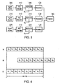
- a preferred embodiment of such an algorithm is the cyclic shifting of the input sequence of symbols. This will now be discussed with reference to FIG. 4.
- the value of N is 10 and the cyclic shifting parameter ⁇ is equal to 3.
- the cyclic shifting scheme is performed both on the input sequence and the output sequence. This leads to a higher flexibility in choosing the distinct interleavers, and thus to a higher number of possible distinct interleavers to be used or chosen.
- interleaver pattern tuples might lead in certain combinations to an identical interleaver behaviour for different streams. These cases depend on the parameter N which is a parameter given by the system.
- the selection of interleaver pattern parameters is therefore preferably done by avoiding those tuples which lead to identical interleavers.
- this tuple is exchanged by another tuple.
- the parameter ⁇ is an integer multiple of 0.5. It acts as the mirroring point if it is an integer number, or it gives the mirroring centre between two positions [ ⁇ -0.5; ⁇ +0.5] if it is not an integer number. Since the mirroring position is now no longer the centre of the vector, the present mirroring scheme is called "biased mirroring".
- FIG. 5 depicts the biased mirroring scheme where the centre position parameter ⁇ is an integer number.
- ⁇ is equal to 3.
- the sequence is mirrored to obtain the sequence of (b) of FIG. 5, and the symbol positions x 9 , x 8 and x 7 are then wrapped around to obtain sequence (c).
- the centre position parameter ⁇ is equal to 2.5 so that a mirroring axis is given between positions x 2 and x 3 .
- the positions are mirrored with wrap around in case the mirrored vector exceeds the boundaries.
- the parameter ⁇ is an integer multiple of 0.5 ranging from 0 to N -0.5. To obtain a mirroring process that is not biased, the parameter ⁇ is set to N /2.
- step (b) is shown for explanation reasons only and is not necessarily explicitely performed.
- a further preferred embodiment for obtaining distinct interleaver patterns is to use variations of the pseudo-random noise generator polynomial. It will be appreciated that the invention is preferably used for decorrelating PN interleavers(or pseudo-noise interleavers or pseudo-random interleavers). As already described above, in a classical block interleaver the input data is written along the rows of a set of memory elements configured as a matrix, and is then read out along the columns.
- the PN interleaver is a variation of the classical block interleaver in which the data is written to memory in sequential order and read out in a pseudo-random order.
- a random interleaver is a permutation block interleaver that is generated from a random permutation based on a random noise source. For example, a noise vector of a given length is generated and the permutation that puts the noise vector in sorted order is used to generate the interleaver.
- the noise vector itself may be generated by a pseudo-random noise generator.
- LFSR linear feedback shift registers
- the stored data values are fed back to the input of the LFSR according to individual wheighting factors c j .
- j 0 , ... , L - 1 i .
- the period of the pseudo-random sequence should be at least N , in a preferred embodiment of the invention, there are N of the provided values used for obtaining the pseudo-random noise vector in case the pseudo-random sequence is greater than N .
- the N lowest values are selected.
- LFSRs are applied in much the same way as previously described but the interleaver pattern parameters p i indicate initialisation values of these LFSR, that are unique for each stream.
- m-sequences are defined as linear feedback shift registers with L stages which produce the maximum possible period q L -1 where q is set to 2 in binary LFSRs.
- the shift registers have to be initialised with a set value ⁇ where 0 ⁇ ⁇ ⁇ q L . This initialisation value has direct impact on the sequence of values with the noise vector.
- j 0 , ... , L - 1 , ⁇ > i .
- LFSR sequence lengths L can be used. It will be appreciated that the system of the invention preferably includes mechanisms for avoiding those parameter combinations that lead to identical interleavers.
- interleavers 300, 310, 320 are depicted as replacing the mother interleavers 230 of FIG. 2, it will be appreciated that the transmitters, and inversely the receivers, might include the mother interleavers 230 in addition to a modification block to obtain the distinct interleavers 300, 310, 320. Thus, it is within the invention to provide an additional block to the mother interleaver 230 for each stream, or to provide interleavers 300, 310, 320 that replace the mother interleaver 230 in each stream. Similarly, implementions can be done by adding blocks before or after the mother interleaver, or by replacing the mother interleaver with distinct interleaver blocks which explicitly follow the functionalities given above.
- the interleaver functionalities are varied with time. If the interleaver pattern parameters p i are tuples containing multiple values, the time variation can apply to each of these values or to only some of them.
- the parameters are preferably chosen in a manner that the number of identical interleavers is reduced to the most extent.
- the technique that has been described in the foregoing allows for decorrelating interleavers for synchronised data transmission. It is well known that in a communication system that includes forward error correction (FEC) interference bursts have more impact on the decoder performance than a multitude of distributed signal errors. Therefore, the invention allows for distributing existing burst interference between two streams to less bursty or signal errors in each stream before the FEC code is decoded. This is done in the embodiments described above for instance by obtaining a multitude of PN interleavers out of a generic PN interleaver, i.e. out of the mother interleaver.
- FEC forward error correction
- Error decorrelation using distinct interleaver patterns is particularly advantageous where the data streams do not differ from each other with respect to the code block length, spreading factor, coding rate etc.
- the invention is therefore in particular suitable for HSDPA with multi-code transmission within the 3GPP context.
- each spreading code representing one data stream.
- This function can also be applied to obtain the cyclic shift parameters ⁇ in , ⁇ out for shifting the input or output sequence.
- the function can be used for mirroring the input as well as the output sequence.
Description
- The invention relates to a data transmitting device for transmitting data on a channel, and to a corresponding data receiving device, and in particular to devices that interleave and deinterleave data streams. The invention is in particular suitable for use with PN interleavers
- It is well known in the art to employ interleavers to obtain some limited form of time diversity, particularly for wireless communications systems which suffer from signal fading effects due to the variance of the radio channel characteristics. An example of a communication system in which transmitters and receivers interleave and deinterleave data, respectively, is depicted in FIG. 1.
- In FIG. 1 a
transmitter channel 140 to areceiver signal source 100, and this data then undergoes forward error correction (FEC) which is done byFEC encoder 110, so that convolutional codes or codes derived therefrom are obtained. The output of theFEC encoder 110 is forwarded as source data stream to theinterleaver 120. - Interleavers, also known as permuters, are used for minimising the effect of noise bursts and fading in a data transmission system. An interleaver is generally implemented using a block structure or a convolutional structure. Variations of block interleavers are also used in communication systems. Other interleavers include S-Random Interleaver, Dithered-Golden Interleaver, Pseudo-Noise (PN) Interleaver, etc.
- A block interleaver formats the encoded data in a rectangular array. Usually, each row of the array constitutes a code word or vector of a length that corresponds to the number of columns. The bits are read out column-wise and transmitted over the channel. At the receiver, the deinterleaver stores the data in the same rectangular array format, but it is read out row-wise, one code word at a time. As a result of this reordering of the data during transmission, a burst of errors is broken down into a number of bursts, which number corresponds to the number of rows in the rectangular array during encoding. Other implementations of block interleavers exist such as those which use only one vector.
- A convolutional interleaver can be used in place of a block interleaver in much the same way.
- The process of interleaving and the actual interleaver functionality will be better understood considering the following example. Assuming that the source data stream which is submitted to the interleaver is an input sequence xk , the function of the interleaver can be described as permuting the input sequence xk to an output sequence yk according to

where f(k) is a permutation function that might for instance be
- The conventional interleaving techniques are especially disadvantageous in communication systems where data of a plurality of different transmitters is simultaneously conveyed on one channel. This is depicted in more detail with reference to FIG. 2.
- Referring to the figure, there are three transmitting devices shown that transmit data on the
same channel 140. The individual transmitters are of essentially the same construction but transmit data fromdifferent signal sources respective encoder 110, and are then interleaved byinterleaver 230 before being modulated bymodulator 130. - The transmission scheme depicted in FIG. 2 is disadvantageous because there is some form of interference between the multiple data streams which negatively affects the system performance. This is since the multiple data streams that share the same radio resource simultaneously, do not fulfil the general requirement of perfect orthogonatility. In particular, the interference can produce burst errors that can render the transmitted data unreadable to the respective receivers.
- The Article "Near Capacity Multiple Access Scheme for Interference Channel using Complex-Valued Signals" by Murata and Yoshida (Electronics Letters October 29, 1998, Vol. 34, No. 22) describes a near full capacity multiple-access scheme using complex-valued signals. For each user a convolutional encoder is employed to correlate neighbouring signals together. A random interleaver which has different patterns for each user is followed to spread the neighbouring correlated signals randomly into different place in the whole sequence.
- The received signal represents the combination of signals from all user signals and are thus correlated together in the whole sequence. The decoding ambiguity is significantly reduced due to the long correlated received signal sequence. An iterative decoding scheme based on symbol-by-symbol estimation is employed to decode the interleaved signals with low computational complexities.
- It is therefore the object of the invention to provide a data transmitting device and a data receiving device having reduced inter-stream interference.
- This object is solved by the invention as claimed in the independent claims.
- The invention provides a data transmitting device for transmitting data on a channel. The device is operable in a communication system that can simultaneously convey data of a plurality of data transmitting devices on one channel. The device comprises an interleaver for interleaving a source data stream, thereby generating an interleaved data stream. Further, means for transmitting said interleaved data stream on said channel is provided. The interleaver characteristics differ from interleaver characteristics of at least one other data transmitting device that simultaneously transmits data on the channel. The invention further provides a corresponding data receiving device.
- By decorrelating the interleavers and deinterleavers for synchronised data transmission, the invention reduces inter-stream interference.
- According to an embodiment of the invention, each interleaver uses an interleaver pattern that differs from the interleaver patterns used simultaneously by the other transmitters that transmit data on the same channel. Interleaver patterns are well known in the art as describing the characteristics of the interleaver. For instance, in the permutation example above, the interleaver pattern corresponds to the function f(k). A channel is any physical or logical entity that is used for conveying data of different transmitters in such a way that interference can occur.
- By using distinct interleaver patterns for each of a plurality of data transmitting devices, inter-stream burst errors are transformed into a multitude of either short burst errors or single errors. Thus, the invention is particularly advantageous when burst errors are the result of the inter-stream interference.
- This is because generally, interference between streams is more or less bursty in nature, i.e. it results in blocks of errors of a length of more than one information unit. By transforming the burst interference into a multitude of shorter errors, the invention improves over the system depicted in FIG. 2 as it allows to decorrelate the interleavers. In the conventional system, all data streams use identical interleavers and FEC codes. If some error pattern occurs that cannot be corrected by the FEC decoder, this will happen to all data streams since the error pattern will also be identical, i.e. fully correlated. By using different interleavers, the error patterns are decorrelated so that in some of the data streams the error pattern still cannot be corrected while in other data streams that have different error patterns, correction can be successfully done. Thus, the invention advantageously increases the system performance.
- Moreover, the invention improves over the conventional FEC schemes because these techniques are either designed to be most effective for single errors (e.g. convolutional code, turbo code) or burst errors (e.g. Reed-Solomon code). In contrast thereto, the invention advantageously allows to distribute the occurring burst errors into a sequence of smaller bursts or single errors.
- Furthermore, the invention can easily be implemented in transmitters and receivers, in particular when the interleaver functionality is constant over time. However, the invention can also be used with interleaver functionalities that vary with time if this should be necessary from a communication system's design point of view. Thus, the invention can be easily adapted to different system designs in a flexible manner.
- The invention is in particular suitable for HSDPA (High-Speed Downlink Packet Access) with multi-code transmission within the 3GPP (3rd Generation Partnership Project) context because error decorrelation using distinct interleaver patterns is particularly applicable in systems where the data streams do not differ from each other with respect to any other parameter such as the code block length, spreading factor, coding rate etc.
- The invention will also have beneficial effects on interference rejection or interference cancellation techniques without affecting their structure. With these schemes at some points an estimate is formed on the transmitted data. Again, if for instance convolutional FEC codes are used, if there is a wrong estimate, this is most probably of bursty nature. Thus, the provision of distinct interleavers according to the invention will also enable the decorrelation of the mentioned bursty wrong estimates which are then less harmful to the FEC decoder.
- The invention is in particular applicable to Direct-Sequence CDMA (Code Division Multiple Access) systems like UMTS (Universal Mobile Telephone Service) which is a third generation (3G) mobile system being developed by ETSI within the ITU's IMT-2000 framework.
- Preferred embodiments of the invention are defined in the dependent claims.
- The invention will now be described in more detail with reference to the accompanying figure drawings in which:
- FIG. 1
- depicts a communication system employing interleaving techniques;
- FIG. 2
- illustrates the transmitter side of a communication system where data from multiple sources are conveyed on one and the same channel, according to the prior art;
- FIG. 3
- illustrates the transmitter side of a communication system according to a preferred embodiment of the present invention;
- FIG.4
- illustrates the cyclic shifting scheme of a preferred embodiment of the present invention;
- FIG. 5
- depicts a biased mirroring scheme of the present invention having an integer mirror position;
- FIG. 6
- illustrates another biased mirroring scheme of the present invention where a fractional mirror position is used; and
- FIG. 7
- depicts an LFSR than can be used with an embodiment of the present invention.
- Preferred embodiments of the invention will be described in more detail with reference to the figure drawings wherein like elements are identified by like reference numbers.
- Referring now to FIG. 3, the invention will be described discussing the transmission side of the communication system. The receiver side will not be discussed in detail in order to not unnecessarily obscure the invention. Knowing how the invention works on the transmitter side will enable the skilled person to design the receiver side in a very straight forward way by providing the corresponding inverse counterparts of the individual units found on the transmitter side.
- As shown in FIG. 3 each data transmitting device that transmits data on the
same channel 140 includes aninterleaver interleavers - There are a number of different possible ways of how to obtain distinct interleaver patterns from these parameters.
- One way of generating interleaver patterns is to modify a given mother interleaver pattern. Before the interleaver can start, an input vector of length N has to be available at the input of the interleaver, i.e. N symbols are required to be input. For the purpose of describing the invention, the term symbol refers to any data element or data unit that can be used for dividing a vector. N denotes the interleaver length and is a parameter given by the communication system to which the interleaver is applied. The invention preferably makes use of interleaver lengths of at least two.
- The modification of the mother interleaver pattern is done by applying an algorithm that depends on the respective interleaver parameter pi . A preferred embodiment of such an algorithm is the cyclic shifting of the input sequence of symbols. This will now be discussed with reference to FIG. 4.
- Assuming the source data stream consists of a sequence of symbols having positions xk , k=0,...,N-1, the data stream undergoes the "cyclic shifting" procedure before interleaving. For this purpose, a cyclic shifting parameter π is introduced for each transmitter i,

- Thus, the input symbol position has changed from xk to x'k according to

where mod is the well known modulo function. It will be appreciated that the relation is identical for any value of π that is offset by N. Therefore, the range for varying the parameter π can be set, without loss of generality, to the integer number range starting from 0 and running to N-1. - When identical mother interleaver patterns are used, a total of N different interleaver patterns can be obtained. Moreover, it will be appreciated that setting the interleaver parameter π to 0 results in using the mother interleaver pattern itself.
- While the cyclic shifting scheme shown in FIG. 4 has been discussed as being performed on the source data stream before interleaving, it will be appreciated that the scheme can also be applied to the output sequence. Assuming that the output sequence symbol positions yk are obtained from the input symbol positions xk according to

where the function f describes the characteristics of the mother interleaver, the cyclic shifting of the output sequence can be described by
- In another preferred embodiment of the present invention, the cyclic shifting scheme is performed both on the input sequence and the output sequence. This leads to a higher flexibility in choosing the distinct interleavers, and thus to a higher number of possible distinct interleavers to be used or chosen.
- It will be appreciated that when the cyclic shifting scheme is performed both before and after the interleaving process, the algorithms can run completely separately from each other but can in an alternative approach also use the same parameters. Therefore, in one embodiment the interleaver parameters pi , i=1,2,3, are used for both cyclic shifting processes in the same manner whereas in another preferred embodiment the parameters pi , i=1,2,3, are actually tuples containing two different values, one being used for cyclic shifting the input sequence and the other being used for cyclic shifting the output sequence:

- Due to the combination of different algorithms, different interleaver pattern tuples might lead in certain combinations to an identical interleaver behaviour for different streams. These cases depend on the parameter N which is a parameter given by the system. The selection of interleaver pattern parameters is therefore preferably done by avoiding those tuples which lead to identical interleavers. When it is determined that a parameter tuple is given that tends to result in an identical interleaver behaviour for different streams, this tuple is exchanged by another tuple.
- Another embodiment of how to obtain distinct interleaver patterns from a mother pattern is the biased mirroring scheme which will now be discussed with reference to FIGS. 5 and 6.
- Mirroring itself would result in a process which can be achieved by simply reversing the order of the positions, i.e.


- The parameter γ is an integer multiple of 0.5. It acts as the mirroring point if it is an integer number, or it gives the mirroring centre between two positions [γ-0.5; γ+0.5] if it is not an integer number. Since the mirroring position is now no longer the centre of the vector, the present mirroring scheme is called "biased mirroring".
- FIG. 5 depicts the biased mirroring scheme where the centre position parameter γ is an integer number. In the example of FIG. 5, γ is equal to 3. In a first step, the sequence is mirrored to obtain the sequence of (b) of FIG. 5, and the symbol positions x9 , x8 and x7 are then wrapped around to obtain sequence (c). In the example of FIG. 6, the centre position parameter γ is equal to 2.5 so that a mirroring axis is given between positions x2 and x3 .
- Thus, the positions are mirrored with wrap around in case the mirrored vector exceeds the boundaries. The parameter γ is an integer multiple of 0.5 ranging from 0 to N-0.5. To obtain a mirroring process that is not biased, the parameter γ is set to N/2.
- Again, the sequence of step (b) is shown for explanation reasons only and is not necessarily explicitely performed.
- Further, the biased mirroring is preferably done on the input sequence, but in another preferred embodiment, the output sequence is modified instead of or in addition to the input sequence:

- A further preferred embodiment for obtaining distinct interleaver patterns is to use variations of the pseudo-random noise generator polynomial. It will be appreciated that the invention is preferably used for decorrelating PN interleavers(or pseudo-noise interleavers or pseudo-random interleavers). As already described above, in a classical block interleaver the input data is written along the rows of a set of memory elements configured as a matrix, and is then read out along the columns. The PN interleaver is a variation of the classical block interleaver in which the data is written to memory in sequential order and read out in a pseudo-random order. A random interleaver is a permutation block interleaver that is generated from a random permutation based on a random noise source. For example, a noise vector of a given length is generated and the permutation that puts the noise vector in sorted order is used to generate the interleaver. In practice, the noise vector itself may be generated by a pseudo-random noise generator.
- A well know technique for pseudo-random noise generators is the usage of linear feedback shift registers (LFSR), an example thereof being shown in FIG. 7. The LFSR consists of a sequence of delay elements such as D flip-
flops 
where L is the number of tabs, i.e. the number of stages of the LFSR. In the example of FIG. 7, the polynomial is ν(x) = x4 + x3 + x2 + x0 since c1 =0 and c0 =c2 =c3 =c4 =1. - One example of how derive a PN sequence from such a register is to use the content of each tap and interpret this as binary representation of an integer number. Alternative schemes are apparent to those of ordinary skill in the art and are therefore not discussed herein in more detail.
- Thus, in the present embodiment the interleaver pattern parameters pi are unique generator polynomials that are different in each data stream:

- As the period of the pseudo-random sequence should be at least N, in a preferred embodiment of the invention, there are N of the provided values used for obtaining the pseudo-random noise vector in case the pseudo-random sequence is greater than N. Preferably, the N lowest values are selected.
- Further, it is preferable to choose as many different generator polynomials with the described proprieties as possible. However, for ease of implementation, those polynomials that fit the requirements with the smallest memory length L, i.e. the number of stages, are selected.
- In a further preferred embodiment of the present invention, LFSRs are applied in much the same way as previously described but the interleaver pattern parameters pi indicate initialisation values of these LFSR, that are unique for each stream. It is well known that m-sequences are defined as linear feedback shift registers with L stages which produce the maximum possible period qL -1 where q is set to 2 in binary LFSRs. The shift registers have to be initialised with a set value κ where 0 < κ < qL . This initialisation value has direct impact on the sequence of values with the noise vector. The value κ is therefore used as interleaver pattern parameters pi :

- While in the description above several embodiments have been discussed that can be used for obtaining distinct interleaver patterns, combinations of some or all of the above described schemes can be used to increase the number of possible distinct interleavers since each parameter can be set individually and independently. This means, that the interleaver pattern parameters pi, i=1,2,3, are multi-value tuples containing one or more cyclic shifting parameters π, πin, πout and/or one or more biased mirroring parameter γ, γin, γout and/or a unique pseudo-random noise generator polynomial ν and/or a unique initialisation value κ, e.g.

- Further, different LFSR sequence lengths L can be used. It will be appreciated that the system of the invention preferably includes mechanisms for avoiding those parameter combinations that lead to identical interleavers.
- Further, while in FIG. 3 the
interleavers distinct interleavers interleavers - Moreover, in a further embodiment, the interleaver functionalities are varied with time. If the interleaver pattern parameters pi are tuples containing multiple values, the time variation can apply to each of these values or to only some of them.
- If it should not be possible to avoid such parameter combinations that result to identical individual interleavers in the data streams, the parameters are preferably chosen in a manner that the number of identical interleavers is reduced to the most extent.
- As will be appreciated by those of ordinary skill in the art, the technique that has been described in the foregoing allows for decorrelating interleavers for synchronised data transmission. It is well known that in a communication system that includes forward error correction (FEC) interference bursts have more impact on the decoder performance than a multitude of distributed signal errors. Therefore, the invention allows for distributing existing burst interference between two streams to less bursty or signal errors in each stream before the FEC code is decoded. This is done in the embodiments described above for instance by obtaining a multitude of PN interleavers out of a generic PN interleaver, i.e. out of the mother interleaver.
- Error decorrelation using distinct interleaver patterns is particularly advantageous where the data streams do not differ from each other with respect to the code block length, spreading factor, coding rate etc. The invention is therefore in particular suitable for HSDPA with multi-code transmission within the 3GPP context.
- In a CDMA system, a handy way of choosing the parameters is to use the spreading code number σ:

- In the example of the 3GPP context, currently a maximum of 512 spreading codes are used simultaneously within one cell, each spreading code representing one data stream.
- A particularly preferred embodiment is to use a simple relation between the interleaver pattern parameters pi , in particular the shifting parameter π, and the data stream ID:

where g is an arbitrary function that converts the integer data stream ID into the interleaver pattern parameter pi . This function can also be applied to obtain the cyclic shift parameters πin, πout for shifting the input or output sequence. - For the mirroring parameters γ, γin, γout, an arbitrary function h is chosen for converting the integer data stream ID into the integer multiple of 0.5 biased mirroring parameter:

- Again, the function can be used for mirroring the input as well as the output sequence.
- In a further preferred embodiment, the functions g and h are chosen to be the identity function, i.e.


Claims (11)
- Data transmitting device for transmitting data on a channel (140), the device being operable in a communication system capable of simultaneously conveying data of a plurality of data transmitting devices on one channel, the data transmitting device comprising:an interleaver (300, 310, 320) for interleaving a source data stream, thereby generating an interleaved data stream;means (130) for transmitting said interleaved data stream on said channel;wherein said interleaver has interleaver characteristics that differ from the interleaver characteristics of at least one other data transmitting device that simultaneously transmits data on said channel; andsaid interleaver generates said interleaved data stream dependent on the data stream identifier;the data transmitting device characterized by further comprisingmeans for receiving a biased mirroring parameter that is unique for the data transmitting device and for performing biased mirroring of data elements of a data stream in response to said unique biased mirroring parameter the biased mirroring is performed by reversing the order of data elements of a data stream, whereby the mirroring point of the transmitted data stream is not the centre of the data stream.
- The data transmitting device of claim 1, wherein said interleaver is a pseudo-noise interleaver, and the data transmitting device further comprises means for receiving a pseudo-noise generator polynomial that is unique for the data transmitting device, and for generating said interleaved data stream using said unique pseudo-noise generator polynomial.
- The data transmitting device of claim 1 or 2, wherein said interleaver is a pseudo-noise interleaver, and the data transmitting device further comprises means for receiving a pseudo-noise generator initialization value that is unique for the data transmitting device, and for initializing said pseudo-random noise generator in response to said unique initialization value.
- The data transmitting device of one of claims 1 to 3, further comprising means for receiving a cyclic shifting parameter that is unique for the data transmitting device, and for cyclic shifting data elements of a data stream in response to said unique cyclic shifting parameter.
- The data transmitting device of one of claims 1 to 4, wherein said interleaver operates in a manner that varies with time.
- The data transmitting device of one of claims 1 to 5, wherein said communication system is a CDMA system.
- The data transmitting device of claim 6, wherein said interleaver generates said interleaved data stream dependent on the spreading code number σ.
- The data transmitting device of one of claims 1 to 7, wherein said communication system is a HSDPA system.
- The data transmitting device of one of claims 1 to 8, wherein said interleaver is a block interleaver.
- The data transmitting device of one of claims 1 to 9, wherein said interleaver is a PN interleaver.
- A method of transmitting data on a channel of a COMA communication system, wherein data of a plurality of data transmitting devices is simultaneously conveyed on one channel, the method comprising the following steps:interleaving a source data stream to generate a first interleaved data stream using a received first interleaving pattern parameter; andinterleaving a source data stream to generate a second interleaved data stream using a received second interleaving pattern parameter; wherein said first and second interleaving pattern parameters are dependent on the data stream identifier,transmitting said first interleaved data by a first data transmitting device and transmitting said second interleaved data stream by a second data transmitting device on said one channel;the method characterized by further comprising the steps ofreceiving a biased mirroring parameter that is unique for the data transmitting device; andperforming biased mirroring of data elements of a data stream in response to the unique biased mirroring parameter the biased mirroring is performed by reversing the order of data elements of a data stream, whereby the mirroring point of the transmitted data stream is not the centre of the data stream.
Priority Applications (1)
| Application Number | Priority Date | Filing Date | Title |
|---|---|---|---|
| DE60130692T DE60130692T2 (en) | 2001-10-10 | 2001-10-10 | Decorrelation of interference from multiple nested data streams |
Applications Claiming Priority (1)
| Application Number | Priority Date | Filing Date | Title |
|---|---|---|---|
| EP01124164A EP1303051B1 (en) | 2001-10-10 | 2001-10-10 | Interference decorrelation of multiple strem interpolated data |
Related Parent Applications (1)
| Application Number | Title | Priority Date | Filing Date |
|---|---|---|---|
| EP01124164A Division EP1303051B1 (en) | 2001-10-10 | 2001-10-10 | Interference decorrelation of multiple strem interpolated data |
Publications (2)
| Publication Number | Publication Date |
|---|---|
| EP1513260A1 EP1513260A1 (en) | 2005-03-09 |
| EP1513260B1 true EP1513260B1 (en) | 2007-09-26 |
Family
ID=8178912
Family Applications (2)
| Application Number | Title | Priority Date | Filing Date |
|---|---|---|---|
| EP04027452A Expired - Lifetime EP1513260B1 (en) | 2001-10-10 | 2001-10-10 | Interference decorrelation of multiple stream interpolated data |
| EP01124164A Expired - Lifetime EP1303051B1 (en) | 2001-10-10 | 2001-10-10 | Interference decorrelation of multiple strem interpolated data |
Family Applications After (1)
| Application Number | Title | Priority Date | Filing Date |
|---|---|---|---|
| EP01124164A Expired - Lifetime EP1303051B1 (en) | 2001-10-10 | 2001-10-10 | Interference decorrelation of multiple strem interpolated data |
Country Status (5)
| Country | Link |
|---|---|
| US (1) | US7688900B2 (en) |
| EP (2) | EP1513260B1 (en) |
| JP (1) | JP3648221B2 (en) |
| CN (1) | CN1319300C (en) |
| DE (1) | DE60110083T2 (en) |
Families Citing this family (17)
| Publication number | Priority date | Publication date | Assignee | Title |
|---|---|---|---|---|
| JP4490922B2 (en) * | 2003-11-21 | 2010-06-30 | パナソニック株式会社 | Multi-antenna transmission apparatus and multi-antenna transmission method |
| US7502982B2 (en) * | 2005-05-18 | 2009-03-10 | Seagate Technology Llc | Iterative detector with ECC in channel domain |
| US7360147B2 (en) * | 2005-05-18 | 2008-04-15 | Seagate Technology Llc | Second stage SOVA detector |
| US7395461B2 (en) | 2005-05-18 | 2008-07-01 | Seagate Technology Llc | Low complexity pseudo-random interleaver |
| CN101286774B (en) * | 2007-04-12 | 2012-07-25 | 华为技术有限公司 | Interleaved multiplexing transmitter system, interleaved duplex transmitter and data processing method |
| CN101291313B (en) * | 2007-04-19 | 2012-01-11 | 华为技术有限公司 | Wireless signal transmitting method, system and mobile station |
| CN101330487B (en) * | 2007-06-19 | 2012-04-04 | 华为技术有限公司 | Symbol interlacing method, apparatus and terminal equipment |
| CN101447960B (en) * | 2007-11-28 | 2012-08-29 | 华为技术有限公司 | Interlayer modulation method, device, orthogonal frequency division multiple access method and transmitter |
| JP5127689B2 (en) * | 2008-12-17 | 2013-01-23 | 日本放送協会 | MIMO transmitting apparatus, receiving apparatus and system |
| CN101771418B (en) | 2009-01-07 | 2014-11-05 | 华为技术有限公司 | Encoding method and device thereof |
| US8601340B2 (en) * | 2011-07-25 | 2013-12-03 | Cortina Systems, Inc. | Time varying data permutation apparatus and methods |
| WO2015078529A1 (en) * | 2013-11-29 | 2015-06-04 | Huawei Technologies Co., Ltd. | Transmission and receiving method in a wireless communication system |
| WO2015089741A1 (en) | 2013-12-17 | 2015-06-25 | 华为技术有限公司 | Data reception method and device, and data sending method and device |
| CN104811410B (en) * | 2014-01-26 | 2018-05-04 | 上海数字电视国家工程研究中心有限公司 | Construction method, sending method and the demodulation method of physical frame |
| CN104901770B (en) * | 2014-03-06 | 2019-12-13 | 中兴通讯股份有限公司 | Error code decorrelation method and device, data processing method, device and system |
| CN107769842B (en) * | 2016-08-17 | 2022-08-09 | 北京三星通信技术研究有限公司 | Interleaving sequence construction, information processing method based on interleaving, transmitting and receiving machine |
| US11006376B2 (en) * | 2017-04-21 | 2021-05-11 | Qualcomm Incorporated | Techniques to encode or decode a self-decodable portion of a physical broadcast channel in a synchronization signal block |
Family Cites Families (21)
| Publication number | Priority date | Publication date | Assignee | Title |
|---|---|---|---|---|
| FR2639781B1 (en) * | 1988-11-25 | 1991-01-04 | Alcatel Thomson Faisceaux | INTERLEAVING METHOD FOR DIGITAL TRANSMISSION DEVICE |
| JP2999110B2 (en) | 1993-12-28 | 2000-01-17 | 株式会社ピーエフユー | Wireless communication method and wireless communication device |
| JP2815007B2 (en) * | 1996-12-05 | 1998-10-27 | 日本電気株式会社 | Variable rate CDMA spreading circuit |
| US6055277A (en) * | 1997-05-29 | 2000-04-25 | Trw Docket No. | Communication system for broadcasting to mobile users |
| GB2326308B (en) * | 1997-06-06 | 2002-06-26 | Nokia Mobile Phones Ltd | Method and apparatus for controlling time diversity in telephony |
| GB2327578A (en) * | 1997-07-18 | 1999-01-27 | Nokia Mobile Phones Ltd | Convolutional interleaver for preventing the transmission of unwanted data |
| US6215762B1 (en) * | 1997-07-22 | 2001-04-10 | Ericsson Inc. | Communication system and method with orthogonal block encoding |
| US6668023B1 (en) * | 1997-12-30 | 2003-12-23 | Paradyne Corporation | Linear block interleaver system and method |
| JPH11215091A (en) | 1998-01-22 | 1999-08-06 | Toshiba Corp | Ofdm signal transmission method and ofdm signal transmitter thereof |
| GB9814960D0 (en) * | 1998-07-10 | 1998-09-09 | Koninkl Philips Electronics Nv | Coding device and communication system using the same |
| US6311075B1 (en) * | 1998-11-24 | 2001-10-30 | Northern Telecom Limited | Antenna and antenna operation method for a cellular radio communications system |
| WO2000060750A1 (en) | 1999-04-02 | 2000-10-12 | Samsung Electronics Co., Ltd. | Interleaving / deinterleaving apparatus and method for a communication system |
| US6154452A (en) * | 1999-05-26 | 2000-11-28 | Xm Satellite Radio Inc. | Method and apparatus for continuous cross-channel interleaving |
| US6687870B1 (en) * | 1999-09-23 | 2004-02-03 | Qualcomm, Incorporated | Method and apparatus for interleaving for information transmission or storage applications |
| KR100334909B1 (en) | 2000-01-19 | 2002-05-04 | 오길록 | Apparatus for Random Interleaver Using Chaotic Signal |
| WO2001056240A1 (en) * | 2000-01-28 | 2001-08-02 | Morphics Technology Inc. | Apparatus and method for sub-chip offset correlation in spread-spectrum communication systems |
| WO2001086821A2 (en) * | 2000-05-05 | 2001-11-15 | Icoding Technology, Inc. | Improved error floor turbo codes |
| KR20040004562A (en) * | 2001-03-27 | 2004-01-13 | 어웨어, 인크. | Receiver Transparent Q-Mode |
| US6973611B2 (en) * | 2001-04-17 | 2005-12-06 | Texas Instruments Incorporated | Interleaved coder and method |
| US7200799B2 (en) * | 2001-04-30 | 2007-04-03 | Regents Of The University Of Minnesota | Area efficient parallel turbo decoding |
| DE60112445T2 (en) * | 2001-10-10 | 2006-04-06 | Matsushita Electric Industrial Co., Ltd., Kadoma | Modification of an interleaver pattern |
-
2001
- 2001-10-10 EP EP04027452A patent/EP1513260B1/en not_active Expired - Lifetime
- 2001-10-10 DE DE60110083T patent/DE60110083T2/en not_active Expired - Lifetime
- 2001-10-10 EP EP01124164A patent/EP1303051B1/en not_active Expired - Lifetime
-
2002
- 2002-09-30 US US10/259,799 patent/US7688900B2/en not_active Expired - Fee Related
- 2002-10-10 CN CNB021529345A patent/CN1319300C/en not_active Expired - Fee Related
- 2002-10-10 JP JP2002297512A patent/JP3648221B2/en not_active Expired - Fee Related
Non-Patent Citations (1)
| Title |
|---|
| None * |
Also Published As
| Publication number | Publication date |
|---|---|
| US7688900B2 (en) | 2010-03-30 |
| JP2003188857A (en) | 2003-07-04 |
| DE60110083D1 (en) | 2005-05-19 |
| EP1513260A1 (en) | 2005-03-09 |
| CN1319300C (en) | 2007-05-30 |
| EP1303051B1 (en) | 2005-04-13 |
| US20030076873A1 (en) | 2003-04-24 |
| CN1417967A (en) | 2003-05-14 |
| DE60110083T2 (en) | 2005-09-08 |
| EP1303051A1 (en) | 2003-04-16 |
| JP3648221B2 (en) | 2005-05-18 |
Similar Documents
| Publication | Publication Date | Title |
|---|---|---|
| EP1513260B1 (en) | Interference decorrelation of multiple stream interpolated data | |
| KR100763378B1 (en) | Method for transmitting/receiving using plurality of antennas, system for the same | |
| EP1303052B1 (en) | Interleaver pattern modification | |
| US6289000B1 (en) | Frame control encoder/decoder for robust OFDM frame transmissions | |
| EP0760182B1 (en) | Method of error protected transmission, method of error protected reception of data and transmission system for transmission of data | |
| EP1100204B1 (en) | Multiplexing method and multiplexing device, and data signal transmission method and data signal transmission device | |
| US20040178934A1 (en) | Efficient bit interleaver for a multi-band OFDM ultra-wideband system | |
| EP1103102B1 (en) | Improved interleavers for turbo code | |
| JP2010093832A (en) | Block interleaving for turbo coding | |
| WO2000045518A2 (en) | Method and apparatus for reducing peak-to-average ratio in a cdma communication system | |
| EP0981219B1 (en) | Encoding apparatus and method | |
| WO2001045272A1 (en) | Interleaver design for parsed parallel concatenated codes | |
| US7684448B2 (en) | Method and apparatus for data interleaving and data de-interleaving against periodical position interference | |
| US20080141098A1 (en) | Low Density Parity Check Encoder Using Costas Array, And Channel Encoder Of High Speed Portable Internet System Comprising The Same And Channel Encoding Method | |
| US6954484B2 (en) | Method and device for generating a channel-coded and subscriber-coded message signal | |
| KR20020048951A (en) | Method and device for transmitting data frames and a method and a device for adapting data rates | |
| Vlachos et al. | Performance study of hybrid spread-spectrum random-access communications | |
| EP1239596A2 (en) | Method of error protected transmission, method of error protected reception of data and transmission system for transmission of data | |
| KR100334909B1 (en) | Apparatus for Random Interleaver Using Chaotic Signal | |
| KR100980858B1 (en) | System and method for wireless sensor network secure using convolution code | |
| DE60130692T2 (en) | Decorrelation of interference from multiple nested data streams | |
| Bisht et al. | Comparative study of interleaves in communication system: IDMA overview | |
| Hadad et al. | Project IEEE 802.16 Broadband Wireless Access Working Group< http://ieee802. org/16> Title IEEE 802.16 TG4 OFDM PHY Proposal for the 802.16 b PHY Layer | |
| WO2001071963A2 (en) | Coding and spreading technique for communications systems |
Legal Events
| Date | Code | Title | Description |
|---|---|---|---|
| PUAI | Public reference made under article 153(3) epc to a published international application that has entered the european phase |
Free format text: ORIGINAL CODE: 0009012 |
|
| AC | Divisional application: reference to earlier application |
Ref document number: 1303051 Country of ref document: EP Kind code of ref document: P |
|
| AK | Designated contracting states |
Kind code of ref document: A1 Designated state(s): DE FR GB |
|
| 17P | Request for examination filed |
Effective date: 20050902 |
|
| AKX | Designation fees paid |
Designated state(s): DE FR GB |
|
| GRAP | Despatch of communication of intention to grant a patent |
Free format text: ORIGINAL CODE: EPIDOSNIGR1 |
|
| GRAS | Grant fee paid |
Free format text: ORIGINAL CODE: EPIDOSNIGR3 |
|
| GRAA | (expected) grant |
Free format text: ORIGINAL CODE: 0009210 |
|
| AC | Divisional application: reference to earlier application |
Ref document number: 1303051 Country of ref document: EP Kind code of ref document: P |
|
| AK | Designated contracting states |
Kind code of ref document: B1 Designated state(s): DE FR GB |
|
| REG | Reference to a national code |
Ref country code: GB Ref legal event code: FG4D |
|
| REF | Corresponds to: |
Ref document number: 60130692 Country of ref document: DE Date of ref document: 20071108 Kind code of ref document: P |
|
| PLBE | No opposition filed within time limit |
Free format text: ORIGINAL CODE: 0009261 |
|
| STAA | Information on the status of an ep patent application or granted ep patent |
Free format text: STATUS: NO OPPOSITION FILED WITHIN TIME LIMIT |
|
| 26N | No opposition filed |
Effective date: 20080627 |
|
| PGFP | Annual fee paid to national office [announced via postgrant information from national office to epo] |
Ref country code: DE Payment date: 20121003 Year of fee payment: 12 Ref country code: FR Payment date: 20121018 Year of fee payment: 12 |
|
| PGFP | Annual fee paid to national office [announced via postgrant information from national office to epo] |
Ref country code: GB Payment date: 20121010 Year of fee payment: 12 |
|
| GBPC | Gb: european patent ceased through non-payment of renewal fee |
Effective date: 20131010 |
|
| PG25 | Lapsed in a contracting state [announced via postgrant information from national office to epo] |
Ref country code: GB Free format text: LAPSE BECAUSE OF NON-PAYMENT OF DUE FEES Effective date: 20131010 |
|
| REG | Reference to a national code |
Ref country code: FR Ref legal event code: ST Effective date: 20140630 |
|
| REG | Reference to a national code |
Ref country code: DE Ref legal event code: R119 Ref document number: 60130692 Country of ref document: DE Effective date: 20140501 |
|
| PG25 | Lapsed in a contracting state [announced via postgrant information from national office to epo] |
Ref country code: DE Free format text: LAPSE BECAUSE OF NON-PAYMENT OF DUE FEES Effective date: 20140501 Ref country code: FR Free format text: LAPSE BECAUSE OF NON-PAYMENT OF DUE FEES Effective date: 20131031 |