EP1514767A1 - Vehicle body structure - Google Patents
Vehicle body structure Download PDFInfo
- Publication number
- EP1514767A1 EP1514767A1 EP04300582A EP04300582A EP1514767A1 EP 1514767 A1 EP1514767 A1 EP 1514767A1 EP 04300582 A EP04300582 A EP 04300582A EP 04300582 A EP04300582 A EP 04300582A EP 1514767 A1 EP1514767 A1 EP 1514767A1
- Authority
- EP
- European Patent Office
- Prior art keywords
- frame
- structure according
- framework
- floor
- interposed
- Prior art date
- Legal status (The legal status is an assumption and is not a legal conclusion. Google has not performed a legal analysis and makes no representation as to the accuracy of the status listed.)
- Withdrawn
Links
Images


Classifications
-
- B—PERFORMING OPERATIONS; TRANSPORTING
- B62—LAND VEHICLES FOR TRAVELLING OTHERWISE THAN ON RAILS
- B62D—MOTOR VEHICLES; TRAILERS
- B62D25/00—Superstructure or monocoque structure sub-units; Parts or details thereof not otherwise provided for
- B62D25/20—Floors or bottom sub-units
-
- B—PERFORMING OPERATIONS; TRANSPORTING
- B62—LAND VEHICLES FOR TRAVELLING OTHERWISE THAN ON RAILS
- B62D—MOTOR VEHICLES; TRAILERS
- B62D25/00—Superstructure or monocoque structure sub-units; Parts or details thereof not otherwise provided for
- B62D25/06—Fixed roofs
-
- B—PERFORMING OPERATIONS; TRANSPORTING
- B62—LAND VEHICLES FOR TRAVELLING OTHERWISE THAN ON RAILS
- B62D—MOTOR VEHICLES; TRAILERS
- B62D27/00—Connections between superstructure or understructure sub-units
- B62D27/04—Connections between superstructure or understructure sub-units resilient
Definitions
- the invention relates to a vehicle structure automobile.
- the invention relates more particularly to a structure of a motor vehicle having a frame on which are rigidly fixed panels such as floors and pavilions.
- the sound comfort of a vehicle depends on the noise level in the cockpit. Part of the noises in the cockpit of a vehicle is generated by the vibration of the panels attached to the frame of the vehicle, such as floors or pavilions.
- the vibration modes of a framework are the overvoltages or peaks of intensity that appear in a structure that deforms under the influence of vibrations. These vibrations are transmitted to panels that react as the skin of a drum.
- the noise reduction generated by the panels is obtained either by an acoustic insulation solution or by decreasing the vibratory response of the panels.
- the vibratory response of the panels must be greater than 200Hz, so that they are not coupled with the frequencies of resonance of the cavities of the frame of the vehicle.
- An object of the present invention is to mitigate all or part of the disadvantages of the prior art noted above.
- the vehicle structure according to the invention is essentially characterized by that one or less of the panels is attached to the framework by fastening means arranged at the level of nodal lines or immobile points during resonant vibration modes of the frame, and in that damping means are interposed between the panel and the framework and / or at the the framework, so as to ensure a vibratory decoupling between the frame and the panel.
- the frame 1 of a motor vehicle represented in FIG. 1 comprises, in its upper part, beams 11 or roof arches and, on the other hand, transverse beams such as crosspieces 12, 13.
- the roof arches 11 and crosspieces 12, 13 delimit a parallelepiped opening intended to be closed by a panel attached to the frame 1 forming a flag.
- the sleepers 12 are fixed to the frame 1 so decoupled. That is, the sleepers 12 are fixed on the frame 1 (roof arches 11) by fastening means arranged at the level of nodal lines or immobile points of the framework during resonant vibration modes of the backbone. More specifically, the cross members 12 are fixed on the arches of flags 11 at the nodes, that is to say calm spots that do not suffer or little displacement during the vibration of the framework 1. The fixation can be achieved by screwing and / or riveting and / or welding.
- nodes or nodal lines are classically determined by calculation by means of software using the finite element technique of mesh of the surface or volume considered.
- other techniques exist to determine these calm points, by example the known technique of Doppler interferometry.
- a damping element 6 is interposed between each end of the crosspiece 12 and the bow of flag 11 corresponding. That is, the crossbar 12 is "isolated" of the frame 1 from a vibratory point of view.
- crosses 12 are solicited mainly in tension / compression and thus dampen vibrations they suffer.
- the damping means 7 is interposed between the flag 3 and the 12.
- the damping means consists of preferably one or more pads 7 made of elastomeric material such as, for example, those marketed under the trade marks SORBOTHANE® or NAVCOM®.
- the means damper has a hardness between 70 and 80 shores about.
- the pads 7 may have parallelepipedal shapes, cylindrical or hemispherical. Preferably, the one or more pads 7 have dimensions of between 30 and 100 mm approximately.
- the pads 7 are preferably placed at the level of bellows deformation of the panel, that is to say at the likely to experience the greatest vibrational displacements (these are determined in the same way as the lines nodal)
- the assembly consisting of the flag 3 and sleepers transverse 12 is decoupled from the rest of the framework 1 (such a floating ceiling). It is found according to the invention a decrease significant vibration of the pavilion responsible for acoustic humming.
- FIG. 3 differs from that previously described in that the sleepers 12 are fixed at roof arches 11 in a conventional manner (ie without decoupling) by means of, for example screws, rivets 26 or point Welding.
- the flag 3 is fastened to the sleepers 12 and / or on the roof arches 11 by fixing means 4 arranged at the level of nodal lines of the frame 1.
- a seal may be provided at the level of the the periphery of pavilion 3, to ensure the seal between the interior and exterior of the cabin.
- a damping means 7 is interposed between the flag 3 and the sleepers 12.
- the flag 3 is decoupled from the rest of the frame 1 (including sleepers), such as a floating ceiling, which reduces significantly the acoustic emission of flag 3.
- the sleepers are replaced or replaced by a crossbar system consisting of two beams 14 crossed and whose ends are attached to arches 11 of flag.
- a damping element 6 can be interposed between each end of a beam 14 of brace and the corresponding roof bow 11, so as to "isolate” from a vibration point of view the cross 14 of the frame 1.
- One or more damping pads 7 are arranged on the cross 14 so as to be interposed between the flag and the cross 14.
- the studs concerned have stiffness and viscoelasticity different, adapted to the frequencies to be damped.
- the arrangement according to the invention also gives the flag good strength and strength without requiring parts and in particular to reduce the number of welds compared to systems known.
- Such an arrangement is furthermore more compatible with a passage of the framework in cataphoresis.
- the structure of vehicle has a floor panel 2 attached to the level of its periphery on the border 10 of an opening 9 formed in the lower part of the framework 1.
- the floor 2 is the one located partly before the vehicle.
- the opening 9 is located for example between a spar 16 and a tunnel 17 of the lower part of the backbone.
- the floor consists for example of one or more stacked metal plates or a sandwich stack stamped metal plates and sheets of material plastic.
- a stiffening rib 8 can be provided on around the floor 2.
- the floor 2 is fixed on the frame 1 by fixing means 4 arranged at the level of lines nodal or immobile points during vibration modes resonant of the framework 1.
- the nodal lines of the first resonance mode of the floor are located on the around the floor 2.
- the bellies are located in the central part of the floor 2.
- the fastening means may comprise screws, rivets, welding points or any other equivalent system.
- damping means 5 are interposed between the floor 2 and the frame 1. These damping means can be made of the same materials as those mentioned above.
- the means dampers are arranged at the level of the bellies, so substantially in the center of the floor with respect to the first mode of vibration.
- the invention provides a vibratory decoupling between the frame 1 and the floor 2.
- the means 5 dampers are preferably constituted by a cord 5 forming a loop closed at the edge 10 of the opening 9.
- This cord 5 is deposited for example, by a nozzle during manufacture of the frame.
- the edge 10 of the opening 9 can have the shape of a concave channel or trowel intended for accommodate the cord 5 shock absorber.
- the arrangement of such a floor according to the present invention good solidity and held in time and does not require additional seals as in the devices of the prior art.
- the invention allows to guarantee a good acoustic comfort despite a fixation of panels by simple screws, rivets or welds.
- the fixing of the panels according to the invention at the level of nodal lines with addition of simple damping means allows to get rid of art fixing devices prior art which include complex filtering means and expensive.
- the arrangement of the floor 2 according to the invention thus allows to seal between the floor 2 and the frame 1 of the "medallion" type as shown in FIG. configuration allows to get rid of the systems sealant seals made at the junction of each pair of adjacent sheets, without any logic geometric.
- the invention applies in particular advantageously vehicle structures whose frame has a stiffness in twist less than 1 billion, and preferably less than 0.8 bn.
- the vibration decoupling of one or more panels in relation to the frame has very serious consequences limited to the impact resistance of the structure (respect for conditions of approval in case of impact with intrusion).
- the invention can of course be applied to other examples of vehicle structure panels.
Abstract
Description
L'invention se rapporte à une structure de véhicule automobile.The invention relates to a vehicle structure automobile.
L'invention concerne plus particulièrement une structure de véhicule automobile comportant une ossature sur laquelle sont fixés rigidement des panneaux tels que des planchers et des pavillons.The invention relates more particularly to a structure of a motor vehicle having a frame on which are rigidly fixed panels such as floors and pavilions.
Le confort sonore d'un véhicule dépend du niveau de bruit dans l'habitacle. Une partie des bruits dans l'habitacle d'un véhicule est générée par la vibration des panneaux fixés sur l'ossature du véhicule, tels que des planchers ou pavillons.The sound comfort of a vehicle depends on the noise level in the cockpit. Part of the noises in the cockpit of a vehicle is generated by the vibration of the panels attached to the frame of the vehicle, such as floors or pavilions.
Les modes de vibration d'une ossature sont les surtensions ou pics d'intensité qui apparaissent dans une structure qui se déforme sous l'influence de vibrations. Ces vibrations sont transmises aux panneaux qui réagissent comme la peau d'un tambour.The vibration modes of a framework are the overvoltages or peaks of intensity that appear in a structure that deforms under the influence of vibrations. These vibrations are transmitted to panels that react as the skin of a drum.
La diminution du bruit généré par les panneaux est obtenue soit par une solution d'isolation acoustique, soit en diminuant la réponse vibratoire des panneaux. En particulier, la réponse vibratoire des panneaux doit être supérieure à 200Hz, afin qu'ils ne soient pas couplés avec les fréquences de résonance des cavités de l'ossature du véhicule.The noise reduction generated by the panels is obtained either by an acoustic insulation solution or by decreasing the vibratory response of the panels. In particular, the vibratory response of the panels must be greater than 200Hz, so that they are not coupled with the frequencies of resonance of the cavities of the frame of the vehicle.
Les solutions connues d'isolation acoustique des panneaux ne sont pas complètement satisfaisantes et entraínent un surcoût important dans la fabrication du véhicule.The known solutions of acoustic insulation of panels are not completely satisfactory and entail a significant additional cost in the manufacture of the vehicle.
Un but de la présente invention est de pallier tout ou partie des inconvénients de l'art antérieur relevés ci-dessus.An object of the present invention is to mitigate all or part of the disadvantages of the prior art noted above.
A cette fin, la structure de véhicule selon l'invention, par ailleurs conforme à la définition générique qu'en donne le préambule ci-dessus, est essentiellement caractérisée en ce que l'un ou moins des panneaux est fixé sur l'ossature par des moyens de fixation disposés au niveau de lignes nodales ou points immobiles lors des modes de vibrations résonnants de l'ossature, et en ce que des moyens amortisseurs sont interposés entre le panneau et l'ossature et/ou au niveau de l'ossature, de façon à assurer un découplage vibratoire entre l'ossature et le panneau.For this purpose, the vehicle structure according to the invention, for otherwise consistent with the generic definition given in preamble above, is essentially characterized by that one or less of the panels is attached to the framework by fastening means arranged at the level of nodal lines or immobile points during resonant vibration modes of the frame, and in that damping means are interposed between the panel and the framework and / or at the the framework, so as to ensure a vibratory decoupling between the frame and the panel.
Par ailleurs, l'invention peut comporter l'une ou plusieurs des caractéristiques suivantes :
- l'ossature a une raideur en torsion inférieure à 1 mrd, et de préférence inférieure à 0,8 mrd,
- les moyens de fixation sont du type vis, rivet ou point de soudure,
- les moyens amortisseurs sont constitués d'un matériau du type élastomère et/ou viscoélastique et/ou silicone,
- les moyens amortisseurs ont une dureté comprise entre 60 à 90 shores environ et de préférence entre 70 et 80 shores,
- la structure comporte un panneau formant plancher fixé sur l'ossature par des moyens de fixation disposés au niveau de lignes nodales ou points immobiles lors des modes de vibrations résonnants de l'ossature, des moyens amortisseurs étant interposés entre le plancher et l'ossature de façon à assurer un découplage vibratoire entre l'ossature et le plancher,
- le plancher est constitué d'une ou plusieurs plaques empilées en matériau métallique embouti et/ou en matière plastique,
- le plancher comporte au moins une nervure de raidissement formée sur au moins une partie de l'une au moins de ses bordures,
- le plancher est fixé au niveau de sa périphérie sur la bordure d'une ouverture formée dans l'ossature,
- la bordure de l'ouverture de l'ossature a la forme d'un canal ou soyage, et en ce que les moyens amortisseurs sont constitués d'un cordon disposé dans le canal de la bordure, de façon à être interposé entre l'ossature et le plancher,
- la structure comporte un panneau formant un pavillon fixé d'une part sur des poutres longitudinales de l'ossature tel que des arcs de pavillon et, d'autre part, sur des poutres transversales telles que des traverses ou des croisillons, le pavillon étant fixé sur le reste de l'ossature par des moyens de fixation disposés au niveau de lignes nodales ou points immobiles lors des modes de vibrations résonnants de l'ossature, des moyens amortisseurs étant interposés entre le pavillon et au moins une poutre transversale de façon à assurer un découplage vibratoire entre le pavillon et l'ossature,
- la structure comporte un panneau formant un pavillon fixé d'une part sur des poutres longitudinales de l'ossature tel que des arcs de pavillon et, d'autre part, sur des poutres transversales telles que des traverses ou des croisillons, l'ensemble constitué du pavillon et des poutres transversales étant fixé sur le reste de l'ossature par des moyens de fixation disposés au niveau de lignes nodales ou points immobiles lors des modes de vibrations résonnants de l'ossature, des moyens amortisseurs étant interposés entre les poutres transversales et le reste de l'ossature de façon à assurer un découplage vibratoire entre d'une part l'ensemble constitué du pavillon et des poutres transversales et, d'autre part, le reste de l'ossature,
- la structure comporte des moyens amortisseurs disposés entre le pavillon et au moins une poutre transversale et constitués d'un ou plusieurs plots en matériau polymère et/ou viscoélastique,
- la structure comporte des moyens amortisseurs interposés entre les extrémités des poutres transversales et le reste de l'ossature et constitués d'un matériau polymère et/ou viscoélastique situé au niveau de l'encastrement de la poutre transversale sur une poutre longitudinale.
- the framework has a torsional stiffness of less than 1 billion, and preferably less than 0.8 billion,
- the fixing means are of the screw, rivet or welding point type,
- the damping means consist of a material of the elastomer and / or viscoelastic and / or silicone type,
- the damping means have a hardness of between 60 to 90 shores and preferably between 70 and 80 shores,
- the structure comprises a floor panel fastened to the framework by fastening means arranged at nodal lines or immobile points during resonant vibration modes of the frame, damping means being interposed between the floor and the frame of to ensure a vibration decoupling between the frame and the floor,
- the floor consists of one or more plates stacked in stamped metal material and / or plastic material,
- the floor has at least one stiffening rib formed on at least a part of at least one of its edges,
- the floor is fixed at its periphery on the edge of an opening formed in the framework,
- the border of the opening of the frame is in the form of a channel or jogging, and in that the damping means consist of a cord arranged in the channel of the edge, so as to be interposed between the frame and the floor,
- the structure comprises a panel forming a roof fixed on the one hand on longitudinal beams of the frame such as roof arches and, on the other hand, on transverse beams such as crosspieces or braces, the roof being fixed on the remainder of the framework by fastening means arranged at nodal lines or immobile points during resonant vibration modes of the frame, damping means being interposed between the roof and at least one transverse beam so as to ensure a vibratory decoupling between the roof and the frame,
- the structure comprises a panel forming a roof fixed on the one hand on longitudinal beams of the frame such as roof arches and, on the other hand, on transverse beams such as crosspieces or crosspieces, the assembly consisting of the flag and transverse beams being fixed on the rest of the frame by fastening means arranged at nodal lines or immobile points during the resonant vibration modes of the frame, damping means being interposed between the transverse beams and the remainder of the framework so as to ensure a vibratory decoupling between on the one hand the assembly consisting of the roof and the transverse beams and, on the other hand, the rest of the framework,
- the structure comprises damping means arranged between the horn and at least one transverse beam and consisting of one or more pads made of polymer and / or viscoelastic material,
- the structure comprises damping means interposed between the ends of the transverse beams and the rest of the frame and consist of a polymeric material and / or viscoelastic located at the recess of the transverse beam on a longitudinal beam.
D'autres particularités et avantages apparaítront à la lecture de la description ci-après, faite en référence aux figures dans lesquelles :
- la figure 1 représente une vue en perspective d'une ossature de véhicule automobile,
- la figure 2 représente une vue en coupe partielle illustrant la fixation d'un pavillon sur une ossature de véhicule selon un premier mode de réalisation de l'invention,
- la figure 3 représente une vue en coupe partielle illustrant la fixation d'un pavillon sur une ossature de véhicule selon un deuxième mode de réalisation de l'invention,
- la figure 4 représente une vue de dessus illustrant un croisillon destiné à supporter un pavillon selon un troisième mode de réalisation de l'invention,
- la figure 5 représente une vue de dessus de la partie inférieure de l'ossature du véhicule de la figure 1 munie d'un plancher,
- la figure 6 représente une demi-coupe selon la ligne AA de la figure 5, illustrant la fixation d'un plancher sur l'ossature selon l'invention,
- la figure 7 représente une vue agrandie de la demi-coupe de la figure 6,
- la figure 8 représente une vue en perspective d'un détail agrandi de la partie inférieure de l'ossature du véhicule de la figure 1 selon un autre mode de réalisation.
- FIG. 1 represents a perspective view of a motor vehicle frame,
- FIG. 2 represents a partial sectional view illustrating the attachment of a roof to a vehicle frame according to a first embodiment of the invention,
- FIG. 3 represents a partial sectional view illustrating the fixing of a roof on a vehicle frame according to a second embodiment of the invention,
- FIG. 4 represents a view from above illustrating a spider for supporting a flag according to a third embodiment of the invention,
- FIG. 5 represents a view from above of the lower part of the frame of the vehicle of FIG. 1 provided with a floor,
- FIG. 6 represents a half-section along the line AA of FIG. 5, illustrating the fixing of a floor on the framework according to the invention,
- FIG. 7 represents an enlarged view of the half section of FIG. 6,
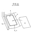
- Figure 8 shows a perspective view of an enlarged detail of the lower portion of the frame of the vehicle of Figure 1 according to another embodiment.
L'ossature 1 de véhicule automobile représentée à la
figure 1 comprend, dans sa partie supérieure, des poutres
longitudinales 11 ou arcs de pavillon et, d'autre part, des
poutres transversales telles que des traverses 12, 13. The
Les arcs de pavillon 11 et traverses 12, 13 délimitent une
ouverture parallélépipédique destinée à être refermée par un
panneau fixé sur l'ossature 1 formant un pavillon.The
Selon un premier mode de réalisation représenté à la
figure 2, les traverses 12 sont fixées à l'ossature 1 de façon
découplée. C'est-à-dire que les traverses 12 sont fixées sur
l'ossature 1 (arcs 11 de pavillon) par des moyens de fixation
disposés au niveau de lignes nodales ou pointes immobiles de
l'ossature lors des modes de vibrations résonnants de
l'ossature. Plus précisément, les traverses 12 sont fixés sur
les arcs de pavillons 11 au niveau des noeuds, c'est-à-dire des
points calmes qui ne subissent pas ou peu de déplacement
lors de la vibration de l'ossature 1. La fixation peut être
réalisée par vissage et/ou rivetage et/ou soudure.According to a first embodiment shown in
2, the
Ces noeuds ou lignes nodales (points immobiles ou quasi immobiles) sont déterminés classiquement par calcul au moyen de logiciels utilisant la technique des éléments finis de maillage de la surface ou du volume considéré. D'autres techniques existent pour déterminer ces points calmes, par exemple la technique connue de l'interférométrie doppler.These nodes or nodal lines (immobile or quasi immobile) are classically determined by calculation by means of software using the finite element technique of mesh of the surface or volume considered. other techniques exist to determine these calm points, by example the known technique of Doppler interferometry.
De plus, selon l'invention, un élément amortisseur 6 est
interposé entre chaque extrémité de la traverse 12 et l'arc de
pavillon 11 correspondant. C'est à dire que la traverse 12 est
"isolée" de l'ossature 1 d'un point de vue vibratoire. Ainsi, les
traverse 12 sont sollicitées principalement en
tension/compression et amortissent ainsi les vibrations
qu'elles subissent.In addition, according to the invention, a
Le pavillon 3 est fixé quant à lui sur les traverses 12 de
façon classique. Un joint 15 d'étanchéité peut être disposé au
niveau de la périphérie du pavillon 3, pour assurer l'étanchéité
entre l'intérieur et l'extérieur de l'habitacle. Selon l'invention,
un moyen 7 amortisseur est interposé entre le pavillon 3 et les
traverses 12. Le moyen amortisseur est constitué de
préférence d'un ou plusieurs plots 7 en matériau élastomère
tel que, par exemple, ceux commercialisés sous les marques
SORBOTHANE® ou NAVCOM®. De préférence, le moyen
amortisseur a une dureté comprise entre 70 et 80 shores
environ.
Les plots 7 peuvent avoir des formes parallélépipédiques,
cylindriques ou hémisphériques. De préférence, le ou les plots
7 ont des dimensions comprises entre 30 et 100 mm environ.The
Les plots 7 sont préférentiellement placés au niveau des
ventres de déformation du panneau, c'est-à-dire aux endroits
susceptibles de subir les plus grands déplacements vibratoires
(ces derniers sont déterminés de la même façon que les lignes
nodales)The
Ainsi, l'ensemble constitué du pavillon 3 et des traverses
transversales 12 est découplé du reste de l'ossature 1 (tel un
plafond flottant). On constate selon l'invention une diminution
significative de la vibration du pavillon responsable de
bourdonnements acoustiques.Thus, the assembly consisting of the
Dans le mode de réalisation représenté à la figure 3, les éléments identiques à ceux décrits ci-dessus sont désignés par les mêmes références numériques et ne sont pas décrits à nouveau en détail.In the embodiment shown in FIG. elements identical to those described above are designated by the same numerical references and are not described in new in detail.
Le mode de réalisation de la figure 3 diffère de celui
précédemment décrit en ce que les traverses 12 sont fixées
aux arcs de pavillon 11 de façon classique (c'est-à-dire sans
découplage) au moyen, par exemple de vis, rivets 26 ou point
de soudure.The embodiment of Figure 3 differs from that
previously described in that the
Le pavillon 3 est fixé quant à lui sur les traverses 12 et/ou
sur les arcs de pavillon 11 par des moyens 4 de fixation
disposés au niveau de lignes nodales de l'ossature 1.The
Un joint 15 d'étanchéité peut être disposé au niveau de la
périphérie du pavillon 3, pour assurer l'étanchéité entre
l'intérieur et l'extérieur de l'habitacle. Comme précédemment,
un moyen 7 amortisseur est interposé entre le pavillon 3 et les
traverses 12. A seal may be provided at the level of the
the periphery of
Ainsi, le pavillon 3 est découplé du reste de l'ossature 1
(traverses comprises), tel un plafond flottant, ce qui réduit
significativement l'émission acoustique du pavillon 3.Thus, the
Dans encore une autre variante de réalisation représentée
à la figure 4, la ou les traverses sont remplacées ou suppléées
par un système en croisillon constitué de deux poutres 14
croisées et dont les extrémités sont fixées aux arcs 11 de
pavillon.In yet another embodiment shown
in Figure 4, the sleepers are replaced or replaced
by a crossbar system consisting of two
Comme précédemment, un élément amortisseur 6 peut
être interposé entre chaque extrémité d'une poutre 14 de
croisillon et l'arc de pavillon 11 correspondant, de façon à
"isoler" d'un point de vue des vibrations le croisillon 14 de
l'ossature 1. Un ou plusieurs plots amortisseurs 7 sont
disposés sur le croisillon 14 de façon à être interposés entre
le pavillon et le croisillon 14.As before, a damping
Par exemple, sur un ensemble de traverses en croix 14, il est possible de prévoir, un, trois, quatre ou cinq plots 7 destinés à amortir respectivement différents modes de vibration du pavillon 3. De façon classique, les modes de vibration croissants (1er, 2ème...) ont des fréquences de vibration croissantes et des amplitudes de vibration décroissantes. A titre d'exemples de configurations :
- dans le cas où un seul plot est utilisé, celui-ci peut être prévu pour amortir le 1er mode de vibration,
- une configuration à trois plots, peut être prévue pour
amortir les 1er
et 2ème modes de vibration - une configuration à quatre plots peut être prévue pour amortir uniquement le 2ème mode de vibration, et
- une configuration à cinq plots peut être prévue pour
amortir les 1er
et 2ème modes de vibration.
- in the case where a single pad is used, it may be provided to dampen the vibration mode 1,
- a configuration with three pins, can be provided to dampen the 1st and 2nd modes of vibration
- a four pads configuration may be provided to only soften the 2 nd mode of vibration, and
- a five-pin configuration can be provided to dampen the 1st and 2nd modes of vibration.
Dans le cas d'un amortissement de deux modes distincts, les plots concernés ont des raideurs et viscoélasticité différentes, adaptées aux fréquences à amortir.In the case of depreciation of two distinct modes, the studs concerned have stiffness and viscoelasticity different, adapted to the frequencies to be damped.
L'agencement selon l'invention confère par ailleurs au pavillon une bonne tenue et solidité sans nécessiter de pièces supplémentaires et permet en particulier de diminuer le nombre de points de soudure par rapport aux systèmes connus. Un tel agencement est en outre plus compatible avec un passage de l'ossature en cataphorèse.The arrangement according to the invention also gives the flag good strength and strength without requiring parts and in particular to reduce the number of welds compared to systems known. Such an arrangement is furthermore more compatible with a passage of the framework in cataphoresis.
En se référant à présent aux figures 5 à 7, la structure de
véhicule comporte un panneau formant plancher 2 fixé au
niveau de sa périphérie sur la bordure 10 d'une ouverture 9
formée dans la partie inférieure de l'ossature 1. Dans cet
exemple de réalisation le plancher 2 est celui situé en partie
avant du véhicule. L'ouverture 9 est située par exemple entre
un longeron 16 et un tunnel 17 de la partie inférieure de
l'ossature.Referring now to Figures 5-7, the structure of
vehicle has a
Le plancher est constitué par exemple d'une ou plusieurs
plaques métalliques empilées ou d'un empilement en sandwich
des plaques métalliques embouties et de plaques en matière
plastique. Une nervure 8 de raidissement peut être prévue sur
le pourtour du plancher 2.The floor consists for example of one or more
stacked metal plates or a sandwich stack
stamped metal plates and sheets of material
plastic. A stiffening
Selon l'invention, le plancher 2 est fixé sur l'ossature 1
par des moyens 4 de fixation disposés au niveau de lignes
nodales ou points immobiles lors des modes de vibrations
résonnants de l'ossature 1. Par exemple, les lignes nodales du
premier mode de résonance du plancher sont situées sur le
pourtour du plancher 2. Les ventres (c'est-à-dire les points de
déformation maximum) sont situés dans la partie centrale du
plancher 2.According to the invention, the
Les moyens de fixation peuvent comporter des vis, rivets, points de soudure ou tout autre système équivalent.The fastening means may comprise screws, rivets, welding points or any other equivalent system.
En outre, des moyens 5 amortisseurs sont interposés
entre le plancher 2 et l'ossature 1. Ces moyens amortisseurs
peuvent être constitués des mêmes matériaux que ceux
mentionnés ci-dessus. De préférence, les moyens
amortisseurs sont disposés au niveau des ventres, donc
sensiblement au centre du plancher en ce qui concerne le
premier mode de vibration.In addition, damping means 5 are interposed
between the
Ainsi, l'invention assure un découplage vibratoire entre
l'ossature 1 et le plancher 2. Les moyens 5 amortisseurs sont
constitués de préférence d'un cordon 5 formant une boucle
fermée au niveau de la bordure 10 de l'ouverture 9. Ce cordon
5 est déposé par exemple, par une buse lors de la fabrication
de l'ossature. A cet effet, la bordure 10 de l'ouverture 9 peut
avoir la forme d'un canal ou soyage concave destiné à
accueillir le cordon 5 amortisseur.Thus, the invention provides a vibratory decoupling between
the
L'agencement d'un tel plancher selon l'invention présente une bonne solidité et tenue dans le temps et ne nécessite pas de joints d'étanchéité supplémentaires comme dans les dispositifs de l'art antérieur. En particulier, l'invention permet de garantir un bon confort acoustique malgré une fixation des panneaux par de simples vis, rivets ou points de soudure. En effet, la fixation des panneaux selon l'invention au niveau de lignes nodales avec ajout de moyens amortisseurs simples, permet de s'affranchir des dispositifs de fixation de l'art antérieur qui comportent des moyens de filtrage complexes et coûteux.The arrangement of such a floor according to the present invention good solidity and held in time and does not require additional seals as in the devices of the prior art. In particular, the invention allows to guarantee a good acoustic comfort despite a fixation of panels by simple screws, rivets or welds. In Indeed, the fixing of the panels according to the invention at the level of nodal lines with addition of simple damping means, allows to get rid of art fixing devices prior art which include complex filtering means and expensive.
L'agencement du plancher 2 selon l'invention permet ainsi
de réaliser une étanchéité entre le plancher 2 et l'ossature 1
du type "médaillon" comme représenté à la figure 8. Cette
configuration permet de s'affranchir des systèmes
d'étanchéités par cordon de mastic réalisés à la jonction de
chaque paire de tôles adjacentes, sans aucune logique
géométrique.The arrangement of the
L'invention s'applique en particulier de façon avantageuse aux structures de véhicules dont l'ossature a une raideur en torsion inférieure à 1 mrd, et de préférence inférieure à 0,8 mrd. De cette façon, le découplage vibratoire d'un ou plusieurs panneaux par rapport à l'ossature a des conséquences très limitées sur la tenue aux chocs de la structure (respect des conditions d'homologation en cas de choc avec intrusion).The invention applies in particular advantageously vehicle structures whose frame has a stiffness in twist less than 1 billion, and preferably less than 0.8 bn. In this way, the vibration decoupling of one or more panels in relation to the frame has very serious consequences limited to the impact resistance of the structure (respect for conditions of approval in case of impact with intrusion).
L'invention peut bien entendu s'appliquer à d'autres exemples de panneaux de structures de véhicule automobile.The invention can of course be applied to other examples of vehicle structure panels.
Claims (14)
Applications Claiming Priority (2)
| Application Number | Priority Date | Filing Date | Title |
|---|---|---|---|
| FR0310620A FR2859442B1 (en) | 2003-09-09 | 2003-09-09 | STRUCTURE OF MOTOR VEHICLE |
| FR0310620 | 2003-09-09 |
Publications (1)
| Publication Number | Publication Date |
|---|---|
| EP1514767A1 true EP1514767A1 (en) | 2005-03-16 |
Family
ID=34130775
Family Applications (1)
| Application Number | Title | Priority Date | Filing Date |
|---|---|---|---|
| EP04300582A Withdrawn EP1514767A1 (en) | 2003-09-09 | 2004-09-08 | Vehicle body structure |
Country Status (2)
| Country | Link |
|---|---|
| EP (1) | EP1514767A1 (en) |
| FR (1) | FR2859442B1 (en) |
Cited By (4)
| Publication number | Priority date | Publication date | Assignee | Title |
|---|---|---|---|---|
| FR2897829A1 (en) * | 2006-02-24 | 2007-08-31 | Peugeot Citroen Automobiles Sa | Two door drophead sedan type motor vehicle structure, has vibration damper including layer of elastic dampening material with visco elastic polymeric material, where damper provides rigid linking between cup and element |
| FR2901337A1 (en) * | 2006-05-22 | 2007-11-23 | Peugeot Citroen Automobiles Sa | Vibration damping tie rod for body shell of e.g. drophead, has damping connection unit including pallet connected with rigid elongated body and co-operating with fixation element via damping elements, where fixation element supports pallet |
| CN105966469A (en) * | 2016-06-14 | 2016-09-28 | 北京新能源汽车股份有限公司 | Connecting structure for front floor and front beam of vehicle and vehicle |
| CN113525517A (en) * | 2021-06-21 | 2021-10-22 | 重庆尊航机械制造有限公司 | Vibration damping type vehicle frame |
Families Citing this family (2)
| Publication number | Priority date | Publication date | Assignee | Title |
|---|---|---|---|---|
| FR2890031B1 (en) * | 2005-08-26 | 2009-04-03 | Inoplast Sa | ROOF STRUCTURE FOR A VEHICLE, VEHICLE PROVIDED WITH SAID STRUCTURE AND METHOD FOR ASSEMBLING IT WITH A VEHICLE BODY |
| FR2890368B1 (en) * | 2005-09-02 | 2007-11-30 | Plastic Omnium Cie | CASH IN WHITE OF MOTOR VEHICLE |
Citations (6)
| Publication number | Priority date | Publication date | Assignee | Title |
|---|---|---|---|---|
| US3149856A (en) * | 1959-08-17 | 1964-09-22 | Smith Corp A O | Motor vehicle having increased ground clearance level floor space |
| DE2344062A1 (en) * | 1972-09-02 | 1974-03-07 | Perkins Engines Ltd | Dynamic insulating material - of heat-setting sheet or strips with embedded electrical conductor |
| US4352520A (en) * | 1977-12-03 | 1982-10-05 | Maschinenfabrik Augsburg-Nurnberg Aktiengesellschaft | Composite of a vehicle frame and body parts |
| DE4401041A1 (en) * | 1993-01-29 | 1994-08-04 | Volkswagen Ag | Body panel component esp. for vehicle liable to vibration |
| US5339745A (en) * | 1992-06-24 | 1994-08-23 | Alusuisse-Lonza Services Ltd. | Sound proofing and vibration dampening elastic connecting element |
| JP2000064354A (en) * | 1998-08-20 | 2000-02-29 | Hitachi Constr Mach Co Ltd | Construction machine |
-
2003
- 2003-09-09 FR FR0310620A patent/FR2859442B1/en not_active Expired - Fee Related
-
2004
- 2004-09-08 EP EP04300582A patent/EP1514767A1/en not_active Withdrawn
Patent Citations (6)
| Publication number | Priority date | Publication date | Assignee | Title |
|---|---|---|---|---|
| US3149856A (en) * | 1959-08-17 | 1964-09-22 | Smith Corp A O | Motor vehicle having increased ground clearance level floor space |
| DE2344062A1 (en) * | 1972-09-02 | 1974-03-07 | Perkins Engines Ltd | Dynamic insulating material - of heat-setting sheet or strips with embedded electrical conductor |
| US4352520A (en) * | 1977-12-03 | 1982-10-05 | Maschinenfabrik Augsburg-Nurnberg Aktiengesellschaft | Composite of a vehicle frame and body parts |
| US5339745A (en) * | 1992-06-24 | 1994-08-23 | Alusuisse-Lonza Services Ltd. | Sound proofing and vibration dampening elastic connecting element |
| DE4401041A1 (en) * | 1993-01-29 | 1994-08-04 | Volkswagen Ag | Body panel component esp. for vehicle liable to vibration |
| JP2000064354A (en) * | 1998-08-20 | 2000-02-29 | Hitachi Constr Mach Co Ltd | Construction machine |
Non-Patent Citations (1)
| Title |
|---|
| PATENT ABSTRACTS OF JAPAN vol. 2000, no. 05 14 September 2000 (2000-09-14) * |
Cited By (4)
| Publication number | Priority date | Publication date | Assignee | Title |
|---|---|---|---|---|
| FR2897829A1 (en) * | 2006-02-24 | 2007-08-31 | Peugeot Citroen Automobiles Sa | Two door drophead sedan type motor vehicle structure, has vibration damper including layer of elastic dampening material with visco elastic polymeric material, where damper provides rigid linking between cup and element |
| FR2901337A1 (en) * | 2006-05-22 | 2007-11-23 | Peugeot Citroen Automobiles Sa | Vibration damping tie rod for body shell of e.g. drophead, has damping connection unit including pallet connected with rigid elongated body and co-operating with fixation element via damping elements, where fixation element supports pallet |
| CN105966469A (en) * | 2016-06-14 | 2016-09-28 | 北京新能源汽车股份有限公司 | Connecting structure for front floor and front beam of vehicle and vehicle |
| CN113525517A (en) * | 2021-06-21 | 2021-10-22 | 重庆尊航机械制造有限公司 | Vibration damping type vehicle frame |
Also Published As
| Publication number | Publication date |
|---|---|
| FR2859442B1 (en) | 2005-10-21 |
| FR2859442A1 (en) | 2005-03-11 |
Similar Documents
| Publication | Publication Date | Title |
|---|---|---|
| EP2560839B1 (en) | Protection panel to be fixed on a part of the body of a motor vehicle and vehicle equipped with such a panel. | |
| JP5698340B2 (en) | Car body rear structure | |
| EP1514767A1 (en) | Vehicle body structure | |
| FR2944498A1 (en) | FRONT PANEL OF MOTOR VEHICLE WITH LARGE SIZE SUPPORT PLATES FOR SHOCK ABSORBERS, AND VEHICLE THEREFOR. | |
| FR2998524A1 (en) | Bumper for use in car, has upper half-shell and lower half-shell that are provided in bumper, and set of shock absorbers whose portions form parts of another set of shock absorbers, where half-shells are made of composite material | |
| FR3055880B1 (en) | UPPER STRUCTURE OF VEHICLE BODYWORK | |
| FR3051172A1 (en) | LATERAL LATERAL ROD FOR VEHICLE | |
| WO2008090274A1 (en) | Device for connecting two structural members of an automotive vehicle | |
| EP2282076A1 (en) | Anti-vibration device for a vehicle and vehicle including such a device. | |
| FR3071812A1 (en) | LOWER STRUCTURE OF VEHICLE | |
| EP4351953A1 (en) | Shock-absorber element for a motor vehicle | |
| FR2897586A1 (en) | Motor vehicle`s plastic rear floor, has floor zone made of elastomer, and plastic body provided with elastomer patch for closing openings, where lower part of body is covered by elastomer layer | |
| JP7006641B2 (en) | Body superstructure | |
| JP4710382B2 (en) | Car body rear structure | |
| JP5618329B2 (en) | Vehicle body superstructure | |
| FR2941670A1 (en) | Motor vehicle structure, has stiffener fixed on sets of elements to rigidify structure, and reinforcement partition for connecting sets of elements to limit displacement of stiffener with respect to wheelhouse during roll of vehicle | |
| JP6917413B2 (en) | Front pillar structure | |
| JP6241469B2 (en) | Vehicle body structure | |
| FR3065432A1 (en) | ROOF STRUCTURE | |
| JP7021655B2 (en) | Body superstructure | |
| JP4328947B2 (en) | Body structure around the rear suspension | |
| FR3102119A1 (en) | Bumper cross member for motor vehicle | |
| FR2964443A1 (en) | Structure element for use in automobile frame, has reinforcement part fixed at longeron in fixing zones such that reinforcement part transmits part of effort applied to support and passage parts along connecting direction | |
| EP3256348A1 (en) | Central support for rear bumper | |
| FR3064582A1 (en) | REAR VEHICLE STRUCTURE |
Legal Events
| Date | Code | Title | Description |
|---|---|---|---|
| PUAI | Public reference made under article 153(3) epc to a published international application that has entered the european phase |
Free format text: ORIGINAL CODE: 0009012 |
|
| AK | Designated contracting states |
Kind code of ref document: A1 Designated state(s): AT BE BG CH CY CZ DE DK EE ES FI FR GB GR HU IE IT LI LU MC NL PL PT RO SE SI SK TR |
|
| AX | Request for extension of the european patent |
Extension state: AL HR LT LV MK |
|
| 17P | Request for examination filed |
Effective date: 20050425 |
|
| AKX | Designation fees paid |
Designated state(s): AT BE BG CH CY CZ DE DK EE ES FI FR GB GR HU IE IT LI LU MC NL PL PT RO SE SI SK TR |
|
| GRAP | Despatch of communication of intention to grant a patent |
Free format text: ORIGINAL CODE: EPIDOSNIGR1 |
|
| STAA | Information on the status of an ep patent application or granted ep patent |
Free format text: STATUS: THE APPLICATION IS DEEMED TO BE WITHDRAWN |
|
| 18D | Application deemed to be withdrawn |
Effective date: 20081007 |