EP1520570A1 - Actuator assembly for a lifter device for disabled persons on wheelchair and prams for children - Google Patents
Actuator assembly for a lifter device for disabled persons on wheelchair and prams for children Download PDFInfo
- Publication number
- EP1520570A1 EP1520570A1 EP04021535A EP04021535A EP1520570A1 EP 1520570 A1 EP1520570 A1 EP 1520570A1 EP 04021535 A EP04021535 A EP 04021535A EP 04021535 A EP04021535 A EP 04021535A EP 1520570 A1 EP1520570 A1 EP 1520570A1
- Authority
- EP
- European Patent Office
- Prior art keywords
- actuator assembly
- transmission
- transmission device
- prams
- wheelchair
- Prior art date
- Legal status (The legal status is an assumption and is not a legal conclusion. Google has not performed a legal analysis and makes no representation as to the accuracy of the status listed.)
- Granted
Links
- 230000005540 biological transmission Effects 0.000 claims abstract description 28
- 230000033001 locomotion Effects 0.000 claims abstract description 5
- 230000007246 mechanism Effects 0.000 claims description 4
- 238000009434 installation Methods 0.000 description 4
- 230000000903 blocking effect Effects 0.000 description 2
- 230000010355 oscillation Effects 0.000 description 2
- 230000000712 assembly Effects 0.000 description 1
- 238000000429 assembly Methods 0.000 description 1
- 238000010276 construction Methods 0.000 description 1
- 230000000630 rising effect Effects 0.000 description 1
- 230000001360 synchronised effect Effects 0.000 description 1
Images


Classifications
-
- A—HUMAN NECESSITIES
- A61—MEDICAL OR VETERINARY SCIENCE; HYGIENE
- A61G—TRANSPORT, PERSONAL CONVEYANCES, OR ACCOMMODATION SPECIALLY ADAPTED FOR PATIENTS OR DISABLED PERSONS; OPERATING TABLES OR CHAIRS; CHAIRS FOR DENTISTRY; FUNERAL DEVICES
- A61G3/00—Ambulance aspects of vehicles; Vehicles with special provisions for transporting patients or disabled persons, or their personal conveyances, e.g. for facilitating access of, or for loading, wheelchairs
- A61G3/02—Loading or unloading personal conveyances; Facilitating access of patients or disabled persons to, or exit from, vehicles
- A61G3/06—Transfer using ramps, lifts or the like
- A61G3/063—Transfer using ramps, lifts or the like using lifts separate from the vehicle, e.g. fixed on the pavement
-
- A—HUMAN NECESSITIES
- A61—MEDICAL OR VETERINARY SCIENCE; HYGIENE
- A61G—TRANSPORT, PERSONAL CONVEYANCES, OR ACCOMMODATION SPECIALLY ADAPTED FOR PATIENTS OR DISABLED PERSONS; OPERATING TABLES OR CHAIRS; CHAIRS FOR DENTISTRY; FUNERAL DEVICES
- A61G3/00—Ambulance aspects of vehicles; Vehicles with special provisions for transporting patients or disabled persons, or their personal conveyances, e.g. for facilitating access of, or for loading, wheelchairs
- A61G3/02—Loading or unloading personal conveyances; Facilitating access of patients or disabled persons to, or exit from, vehicles
- A61G3/06—Transfer using ramps, lifts or the like
- A61G3/062—Transfer using ramps, lifts or the like using lifts connected to the vehicle
-
- B—PERFORMING OPERATIONS; TRANSPORTING
- B66—HOISTING; LIFTING; HAULING
- B66B—ELEVATORS; ESCALATORS OR MOVING WALKWAYS
- B66B9/00—Kinds or types of lifts in, or associated with, buildings or other structures
- B66B9/06—Kinds or types of lifts in, or associated with, buildings or other structures inclined, e.g. serving blast furnaces
- B66B9/08—Kinds or types of lifts in, or associated with, buildings or other structures inclined, e.g. serving blast furnaces associated with stairways, e.g. for transporting disabled persons
-
- A—HUMAN NECESSITIES
- A61—MEDICAL OR VETERINARY SCIENCE; HYGIENE
- A61G—TRANSPORT, PERSONAL CONVEYANCES, OR ACCOMMODATION SPECIALLY ADAPTED FOR PATIENTS OR DISABLED PERSONS; OPERATING TABLES OR CHAIRS; CHAIRS FOR DENTISTRY; FUNERAL DEVICES
- A61G2220/00—Adaptations of particular transporting means
- A61G2220/16—Buses
Definitions
- the present invention relates in general to lifter devices and in particular it pertains to equipment to facilitate the access of disabled persons and children's prams aboard vehicles, for example collective transport vehicles, or to fixed installations such as public buildings, museums and the like.
- the invention can be applied in particular to a lifter device to be permanently applied to a vehicle or to a fixed installation to overcome a difference in level to access said vehicle or said fixed installation.
- the present invention can nonetheless be applied more in general to lifter devices of various kinds for persons or for loads, in vehicles or in private, commercial or industrial buildings.
- the invention can, for example, be applied in lifter devices under the body or over the body for automobiles or buses, in lifter devices over the box or under the box for trains, in buildings such as shopping centres or the like.
- the main drawback in actuators for known lifter devices consists of the possibility of sticking and blocking of the vertical actuation system of the lifting platform, in particular if the load on the platform is displaced on one side.
- the object of the present invention is to provide an actuator assembly for lifter devices which is simple, robust and reliable and which allows to avoid risks of sticking.
- an actuator assembly comprises an electric motor 40 and at least one transmission device 42.
- the or each transmission device 42 is connected to two arms 44, 46 of an articulated parallelogram device associated to a vertically movable platform.
- the transmission assembly 42 comprises a fixed case 48 bearing a chain of transmission members provided exclusively with rotary motion.
- Each transmission device 42 comprises a first transmission mechanism with worm screw 50 and helical wheel 52.
- the worm screw 50 constitutes the input member of the transmission device 42.
- the first helical wheel 52 is integral with a shaft bearing a second worm screw 54 freely rotatable around an axis that is transverse relative to the axis of rotation of the first worm screw 50.
- the second worm screw 54 co-operates with a second helical wheel 56 integral with a shaft bearing a third worm screw 58 rotatable around an axis that is orthogonal relative to the axis of rotation of the second worm screw 54.
- the third worm screw 58 meshes with a sector of helical wheel 60 constituting the output member of the transmission device 42.
- two transmission devices 42 are provided, situated on two opposite sides of a vertically movable lifting platform.
- the toothed sector 60 is keyed onto a transverse synchronisation shaft 62 mounted oscillating relative to the case 48 of the transmission device 42 around a horizontal case 64.
- the toothed sector 60 is integral with the lower arm 44 of the articulated parallelogram device.
- the transverse shaft 62 mutually connects the toothed sectors 60 of two transmission assemblies 42 situated on the two sides of the platform and its purpose is mutually to synchronise the oscillation movements of the two lower arms 44.
- the electric motor 40 is connected to the two transmission devices 42 by means of positive drive belts 66, 68.
- the reference number 70 designates a retracting lifter device comprising a fixed frame 72 to be encased within a seat (not shown) provided below the plane of access to a vehicle or to a fixed installation.
- the fixed frame 72 has a general U-shaped configuration, with two parallel branches 74, 76 mutually joined by a rear branch 78.
- the fixed frame 72 bears a carriage 80, movable in the longitudinal direction between an extracted position and a retracted position.
- the carriage 80 bears an actuator assembly according to the invention, having an electric motor 40 and two transmission devices 42.
- Each transmission device 42 bears two arms 44, 46 connected to a vertically movable platform 82 according to an articulated parallelogram configuration.
- the transmission devices 42 according to the present invention allow to avoid the sticking or blocking of the vertical motion of the platform 82 even under conditions in which the load on the platform 82 is laterally unbalanced.
- Figures 4 and 5 show a second example of application of an actuator assembly according to the invention.
- the actuator assembly 40, 42 is applied to a lifter device including a base structure 84 provided with a vertically movable platform 82 able to receive and to lift and lower a wheelchair 86.
- the actuator assembly 40, 42 is borne by the base structure 84 and it is connected to the vertically movable platform 82 by means of the articulated parallelogram device 44, 46.
- FIG. 6 An additional example of application of the actuator assembly according to the invention is shown in Figure 6.
- the actuator assembly 40, 42 is applied to a lifter device including a vertically movable platform borne by a vertical upright 88.
- the lifter device is mounted rotatable around a vertical axis 90 and the actuator assembly 40, 42 is used to command the rotation of the entire lifter device around the vertical axis 90 in the direction indicated by the double arrow 92 between an inoperative position and an operative position, and vice versa.
Abstract
Description
- The present invention relates in general to lifter devices and in particular it pertains to equipment to facilitate the access of disabled persons and children's prams aboard vehicles, for example collective transport vehicles, or to fixed installations such as public buildings, museums and the like.
- The invention can be applied in particular to a lifter device to be permanently applied to a vehicle or to a fixed installation to overcome a difference in level to access said vehicle or said fixed installation. The present invention can nonetheless be applied more in general to lifter devices of various kinds for persons or for loads, in vehicles or in private, commercial or industrial buildings. The invention can, for example, be applied in lifter devices under the body or over the body for automobiles or buses, in lifter devices over the box or under the box for trains, in buildings such as shopping centres or the like.
- The main drawback in actuators for known lifter devices consists of the possibility of sticking and blocking of the vertical actuation system of the lifting platform, in particular if the load on the platform is displaced on one side.
- The object of the present invention is to provide an actuator assembly for lifter devices which is simple, robust and reliable and which allows to avoid risks of sticking.
- According to the present invention, said object and other objects are achieved by an actuator assembly having the characteristics set out in the claims.
- The characteristics and advantages of the present invention shall become readily apparent in the detailed description that follows, provided purely by way of non limiting example, with reference to the accompanying drawings, in which:
- Figure 1 is a schematic perspective view of an actuator assembly according to the present invention,
- Figure 2 is a lateral view according to the arrow II of Figure 1,
- Figure 3 is a perspective view of a first embodiment of an actuator assembly according to the invention,
- Figure 4 is a perspective view of a second example of application of an actuator assembly according to the invention,
- Figure 5 is a perspective view of the part designated by the arrow V in Figure 4, and
- Figure 6 is a perspective view of a third example of application of an actuator assembly according to the invention.
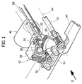
- With reference to Figures 1 and 2, an actuator assembly according to the invention comprises an
electric motor 40 and at least onetransmission device 42. The or eachtransmission device 42 is connected to twoarms - The
transmission assembly 42 comprises a fixedcase 48 bearing a chain of transmission members provided exclusively with rotary motion. Eachtransmission device 42 comprises a first transmission mechanism withworm screw 50 andhelical wheel 52. Theworm screw 50 constitutes the input member of thetransmission device 42. The firsthelical wheel 52 is integral with a shaft bearing asecond worm screw 54 freely rotatable around an axis that is transverse relative to the axis of rotation of thefirst worm screw 50. Thesecond worm screw 54 co-operates with a secondhelical wheel 56 integral with a shaft bearing athird worm screw 58 rotatable around an axis that is orthogonal relative to the axis of rotation of thesecond worm screw 54. The third worm screw 58 meshes with a sector ofhelical wheel 60 constituting the output member of thetransmission device 42. - In an embodiment of the invention, two
transmission devices 42 are provided, situated on two opposite sides of a vertically movable lifting platform. Thetoothed sector 60 is keyed onto atransverse synchronisation shaft 62 mounted oscillating relative to thecase 48 of thetransmission device 42 around ahorizontal case 64. Thetoothed sector 60 is integral with thelower arm 44 of the articulated parallelogram device. Thetransverse shaft 62 mutually connects thetoothed sectors 60 of twotransmission assemblies 42 situated on the two sides of the platform and its purpose is mutually to synchronise the oscillation movements of the twolower arms 44. Theelectric motor 40 is connected to the twotransmission devices 42 by means ofpositive drive belts - It is readily apparent that the rotation of the output shaft of the
motor 40 causes the oscillation of thetoothed sector 60 around theaxis 64. Thetoothed sector 60 commands, through the articulatedparallelogram device - With reference to Figure 3, the
reference number 70 designates a retracting lifter device comprising afixed frame 72 to be encased within a seat (not shown) provided below the plane of access to a vehicle or to a fixed installation. Thefixed frame 72 has a general U-shaped configuration, with twoparallel branches - The
fixed frame 72 bears acarriage 80, movable in the longitudinal direction between an extracted position and a retracted position. Thecarriage 80 bears an actuator assembly according to the invention, having anelectric motor 40 and twotransmission devices 42. Eachtransmission device 42 bears twoarms movable platform 82 according to an articulated parallelogram configuration. - The
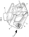
transmission devices 42 according to the present invention, mutually synchronised by means of thetransverse shaft 62, allow to avoid the sticking or blocking of the vertical motion of theplatform 82 even under conditions in which the load on theplatform 82 is laterally unbalanced. - Figures 4 and 5 show a second example of application of an actuator assembly according to the invention. In this case, the
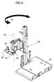
actuator assembly base structure 84 provided with a verticallymovable platform 82 able to receive and to lift and lower awheelchair 86. Theactuator assembly base structure 84 and it is connected to the verticallymovable platform 82 by means of the articulatedparallelogram device - An additional example of application of the actuator assembly according to the invention is shown in Figure 6. In this case, the
actuator assembly actuator assembly double arrow 92 between an inoperative position and an operative position, and vice versa. - Naturally, without altering the principle of the invention, the construction details and the embodiments may be widely varied relative to what is described and illustrated herein, without thereby departing from the scope of the present invention as defined in the appended claims.
Claims (7)
- An actuator assembly for a lifter device for disabled persons on wheelchair and prams for children comprising a vertically movable platform (82) able to move between a lowered position and a raised position to overcome a difference in level of access, the actuator assembly comprising an electric motor (40) and a transmission device (42) including a chain of transmission members, characterised in that said transmission members (50,52;54,56;58,60) are provided exclusively with rotary motion.
- Actuator assembly as claimed in claim 1, characterised in that the transmission device (42) comprises at least one transmission mechanism with worm screw and helical wheel.
- Actuator assembly as claimed in claim 2, characterised in that said transmission device (42) comprises three transmission mechanisms with worm screw and helical wheel (50,52;54,56;58,60) mutually connected in series.
- Actuator assembly as claimed in claim 3, characterised in that the transmission device (42) comprises a sector of helical wheel (60) integral in rotation with an arm (44) of an articulated parallelogram device.
- Actuator assembly as claimed in claim 1, characterised in that it comprises two transmission devices (42) positioned at respective sides of the platform (82).
- Actuator assembly as claimed in claim 5, characterised in that each transmission device (42) is connected to a pair of arms (44,46) arranged according to an articulated parallelogram configuration.
- Actuator assembly as claimed in claim 5, characterised in that it comprises a synchronisation shaft (62) which mutually connects the output members (60) of the two transmission mechanisms (42).
Applications Claiming Priority (2)
| Application Number | Priority Date | Filing Date | Title |
|---|---|---|---|
| ITTO20030759 | 2003-09-30 | ||
| IT000759A ITTO20030759A1 (en) | 2003-09-30 | 2003-09-30 | ACTUATOR GROUP FOR A LIFTING DEVICE FOR |
Publications (2)
| Publication Number | Publication Date |
|---|---|
| EP1520570A1 true EP1520570A1 (en) | 2005-04-06 |
| EP1520570B1 EP1520570B1 (en) | 2006-12-06 |
Family
ID=34308158
Family Applications (1)
| Application Number | Title | Priority Date | Filing Date |
|---|---|---|---|
| EP04021535A Active EP1520570B1 (en) | 2003-09-30 | 2004-09-10 | Actuator assembly for a lifter device for disabled persons on wheelchair and prams for children |
Country Status (7)
| Country | Link |
|---|---|
| US (1) | US20050098393A1 (en) |
| EP (1) | EP1520570B1 (en) |
| AT (1) | ATE347343T1 (en) |
| CA (1) | CA2483136A1 (en) |
| DE (1) | DE602004003537T2 (en) |
| ES (1) | ES2278253T3 (en) |
| IT (1) | ITTO20030759A1 (en) |
Cited By (2)
| Publication number | Priority date | Publication date | Assignee | Title |
|---|---|---|---|---|
| FR2918559A1 (en) * | 2007-07-13 | 2009-01-16 | Alain Bourgeois | LIFTING DEVICE FOR WHEELCHAIR |
| WO2017140960A1 (en) * | 2016-02-18 | 2017-08-24 | Fein Michel | Platform for moving a wheelchair |
Families Citing this family (1)
| Publication number | Priority date | Publication date | Assignee | Title |
|---|---|---|---|---|
| US10470951B2 (en) * | 2015-11-12 | 2019-11-12 | All-Terrian Conversions, LLC | Wheelchair lift |
Citations (3)
| Publication number | Priority date | Publication date | Assignee | Title |
|---|---|---|---|---|
| US4499970A (en) * | 1982-06-25 | 1985-02-19 | Environmental Equipment Corporation | Wayside wheelchair lift |
| US5556250A (en) * | 1988-11-05 | 1996-09-17 | Ricon Corporation | Vehicle lifts |
| US6203266B1 (en) * | 1997-10-27 | 2001-03-20 | Ricon Corporation | Power safety barrier for wheelchair lift |
Family Cites Families (6)
| Publication number | Priority date | Publication date | Assignee | Title |
|---|---|---|---|---|
| US556250A (en) * | 1896-03-10 | Bicycle-saddle | ||
| US4140230A (en) * | 1977-05-12 | 1979-02-20 | Pearson Marvin R | Powered loading platform |
| US4124099A (en) * | 1977-10-04 | 1978-11-07 | General Motors Corporation | Wheelchair lift device |
| US4124098A (en) * | 1977-10-04 | 1978-11-07 | General Motors Corporation | Wheelchair lift device |
| CA1109831A (en) * | 1981-02-23 | 1981-09-29 | John C. Kingston | Mechanism for transfer of wheelchair confined passengers to and from passenger carrying vehicles |
| DE19901032A1 (en) * | 1999-01-14 | 2000-07-20 | Pierburg Ag | Electric fuel pump |
-
2003
- 2003-09-30 IT IT000759A patent/ITTO20030759A1/en unknown
-
2004
- 2004-09-10 DE DE602004003537T patent/DE602004003537T2/en active Active
- 2004-09-10 EP EP04021535A patent/EP1520570B1/en active Active
- 2004-09-10 AT AT04021535T patent/ATE347343T1/en not_active IP Right Cessation
- 2004-09-10 ES ES04021535T patent/ES2278253T3/en active Active
- 2004-09-29 CA CA002483136A patent/CA2483136A1/en not_active Abandoned
- 2004-09-30 US US10/954,620 patent/US20050098393A1/en not_active Abandoned
Patent Citations (3)
| Publication number | Priority date | Publication date | Assignee | Title |
|---|---|---|---|---|
| US4499970A (en) * | 1982-06-25 | 1985-02-19 | Environmental Equipment Corporation | Wayside wheelchair lift |
| US5556250A (en) * | 1988-11-05 | 1996-09-17 | Ricon Corporation | Vehicle lifts |
| US6203266B1 (en) * | 1997-10-27 | 2001-03-20 | Ricon Corporation | Power safety barrier for wheelchair lift |
Cited By (5)
| Publication number | Priority date | Publication date | Assignee | Title |
|---|---|---|---|---|
| FR2918559A1 (en) * | 2007-07-13 | 2009-01-16 | Alain Bourgeois | LIFTING DEVICE FOR WHEELCHAIR |
| WO2009034272A2 (en) * | 2007-07-13 | 2009-03-19 | Alain Bourgeois | Lift device for a rolling chair |
| WO2009034272A3 (en) * | 2007-07-13 | 2009-05-07 | Alain Bourgeois | Lift device for a rolling chair |
| WO2017140960A1 (en) * | 2016-02-18 | 2017-08-24 | Fein Michel | Platform for moving a wheelchair |
| FR3047983A1 (en) * | 2016-02-18 | 2017-08-25 | Michel Fein | PLATFORM FOR MOVING A WHEELCHAIR |
Also Published As
| Publication number | Publication date |
|---|---|
| US20050098393A1 (en) | 2005-05-12 |
| ES2278253T3 (en) | 2007-08-01 |
| CA2483136A1 (en) | 2005-03-30 |
| EP1520570B1 (en) | 2006-12-06 |
| ATE347343T1 (en) | 2006-12-15 |
| ITTO20030759A1 (en) | 2005-04-01 |
| DE602004003537T2 (en) | 2007-09-27 |
| DE602004003537D1 (en) | 2007-01-18 |
Similar Documents
| Publication | Publication Date | Title |
|---|---|---|
| US8375496B1 (en) | Fold out ramp | |
| US9271883B2 (en) | Ramp assembly with tilt sensor | |
| US3887217A (en) | Retractable step for vehicles | |
| US4365924A (en) | Disabled person transfer device | |
| US8869333B2 (en) | Ramp assembly with tilt sensor | |
| US8533884B1 (en) | Fold out ramp | |
| CA2630382A1 (en) | Latch for a fold out ramp | |
| US6860701B2 (en) | Wheelchair ramp with side barriers | |
| US7396202B1 (en) | Lift and carrier assembly for a personal-transportation vehicle | |
| CA3072298A1 (en) | Movable baseplate cover and inboard barrier gate of a lift system for a motorized vehicle | |
| EP1520570A1 (en) | Actuator assembly for a lifter device for disabled persons on wheelchair and prams for children | |
| US7033127B2 (en) | Powered, folding ramp for minivan | |
| JP2009082568A (en) | Assistive chair for vehicle for the disabled | |
| FR2506154A1 (en) | Wheelchair lift mechanism for side loading vehicle - uses electrically controlled lifting arm mounted on screws running across vehicle floor | |
| JP2019141287A (en) | Wheelchair carrying-in/out device mounted to automobile | |
| US20160067121A1 (en) | Lift apparatus for a vehicle | |
| KR101088851B1 (en) | Slope for train with two-way folded hinge | |
| JP3463024B2 (en) | Wheelchair bumper | |
| JP3380893B2 (en) | Electric wheelchair stair climbing mechanism | |
| CN108843085B (en) | Three-dimensional parking device | |
| JP2010100376A (en) | Vehicle lifting device | |
| ES2362680T3 (en) | SLIDING SLOPE TO INSTALL IN A VEHICLE OF PUBLIC TRANSPORTATION OF PERSONS WITH A INCLUDED FLAT SURFACE. | |
| JP2004210020A (en) | Lift for wheel chair | |
| JPH0748565Y2 (en) | Object transfer device | |
| JP4239197B2 (en) | SLIDE FRAME DRIVE DEVICE FOR VEHICLE OBTAINMENT |
Legal Events
| Date | Code | Title | Description |
|---|---|---|---|
| PUAI | Public reference made under article 153(3) epc to a published international application that has entered the european phase |
Free format text: ORIGINAL CODE: 0009012 |
|
| AK | Designated contracting states |
Kind code of ref document: A1 Designated state(s): AT BE BG CH CY CZ DE DK EE ES FI FR GB GR HU IE IT LI LU MC NL PL PT RO SE SI SK TR |
|
| AX | Request for extension of the european patent |
Extension state: AL HR LT LV MK |
|
| 17P | Request for examination filed |
Effective date: 20051004 |
|
| AKX | Designation fees paid |
Designated state(s): AT BE BG CH CY CZ DE DK EE ES FI FR GB GR HU IE IT LI LU MC NL PL PT RO SE SI SK TR |
|
| GRAP | Despatch of communication of intention to grant a patent |
Free format text: ORIGINAL CODE: EPIDOSNIGR1 |
|
| GRAS | Grant fee paid |
Free format text: ORIGINAL CODE: EPIDOSNIGR3 |
|
| GRAA | (expected) grant |
Free format text: ORIGINAL CODE: 0009210 |
|
| AK | Designated contracting states |
Kind code of ref document: B1 Designated state(s): AT BE BG CH CY CZ DE DK EE ES FI FR GB GR HU IE IT LI LU MC NL PL PT RO SE SI SK TR |
|
| PG25 | Lapsed in a contracting state [announced via postgrant information from national office to epo] |
Ref country code: SI Free format text: LAPSE BECAUSE OF FAILURE TO SUBMIT A TRANSLATION OF THE DESCRIPTION OR TO PAY THE FEE WITHIN THE PRESCRIBED TIME-LIMIT Effective date: 20061206 Ref country code: IT Free format text: LAPSE BECAUSE OF FAILURE TO SUBMIT A TRANSLATION OF THE DESCRIPTION OR TO PAY THE FEE WITHIN THE PRESCRIBED TIME-LIMIT;WARNING: LAPSES OF ITALIAN PATENTS WITH EFFECTIVE DATE BEFORE 2007 MAY HAVE OCCURRED AT ANY TIME BEFORE 2007. THE CORRECT EFFECTIVE DATE MAY BE DIFFERENT FROM THE ONE RECORDED. Effective date: 20061206 Ref country code: DK Free format text: LAPSE BECAUSE OF FAILURE TO SUBMIT A TRANSLATION OF THE DESCRIPTION OR TO PAY THE FEE WITHIN THE PRESCRIBED TIME-LIMIT Effective date: 20061206 Ref country code: BE Free format text: LAPSE BECAUSE OF FAILURE TO SUBMIT A TRANSLATION OF THE DESCRIPTION OR TO PAY THE FEE WITHIN THE PRESCRIBED TIME-LIMIT Effective date: 20061206 Ref country code: LI Free format text: LAPSE BECAUSE OF FAILURE TO SUBMIT A TRANSLATION OF THE DESCRIPTION OR TO PAY THE FEE WITHIN THE PRESCRIBED TIME-LIMIT Effective date: 20061206 Ref country code: AT Free format text: LAPSE BECAUSE OF FAILURE TO SUBMIT A TRANSLATION OF THE DESCRIPTION OR TO PAY THE FEE WITHIN THE PRESCRIBED TIME-LIMIT Effective date: 20061206 Ref country code: CZ Free format text: LAPSE BECAUSE OF FAILURE TO SUBMIT A TRANSLATION OF THE DESCRIPTION OR TO PAY THE FEE WITHIN THE PRESCRIBED TIME-LIMIT Effective date: 20061206 Ref country code: FI Free format text: LAPSE BECAUSE OF FAILURE TO SUBMIT A TRANSLATION OF THE DESCRIPTION OR TO PAY THE FEE WITHIN THE PRESCRIBED TIME-LIMIT Effective date: 20061206 Ref country code: NL Free format text: LAPSE BECAUSE OF FAILURE TO SUBMIT A TRANSLATION OF THE DESCRIPTION OR TO PAY THE FEE WITHIN THE PRESCRIBED TIME-LIMIT Effective date: 20061206 Ref country code: PL Free format text: LAPSE BECAUSE OF FAILURE TO SUBMIT A TRANSLATION OF THE DESCRIPTION OR TO PAY THE FEE WITHIN THE PRESCRIBED TIME-LIMIT Effective date: 20061206 Ref country code: CH Free format text: LAPSE BECAUSE OF FAILURE TO SUBMIT A TRANSLATION OF THE DESCRIPTION OR TO PAY THE FEE WITHIN THE PRESCRIBED TIME-LIMIT Effective date: 20061206 Ref country code: RO Free format text: LAPSE BECAUSE OF FAILURE TO SUBMIT A TRANSLATION OF THE DESCRIPTION OR TO PAY THE FEE WITHIN THE PRESCRIBED TIME-LIMIT Effective date: 20061206 Ref country code: SK Free format text: LAPSE BECAUSE OF FAILURE TO SUBMIT A TRANSLATION OF THE DESCRIPTION OR TO PAY THE FEE WITHIN THE PRESCRIBED TIME-LIMIT Effective date: 20061206 |
|
| REG | Reference to a national code |
Ref country code: GB Ref legal event code: FG4D |
|
| REG | Reference to a national code |
Ref country code: CH Ref legal event code: EP |
|
| REG | Reference to a national code |
Ref country code: IE Ref legal event code: FG4D |
|
| REF | Corresponds to: |
Ref document number: 602004003537 Country of ref document: DE Date of ref document: 20070118 Kind code of ref document: P |
|
| PG25 | Lapsed in a contracting state [announced via postgrant information from national office to epo] |
Ref country code: SE Free format text: LAPSE BECAUSE OF FAILURE TO SUBMIT A TRANSLATION OF THE DESCRIPTION OR TO PAY THE FEE WITHIN THE PRESCRIBED TIME-LIMIT Effective date: 20070306 Ref country code: BG Free format text: LAPSE BECAUSE OF FAILURE TO SUBMIT A TRANSLATION OF THE DESCRIPTION OR TO PAY THE FEE WITHIN THE PRESCRIBED TIME-LIMIT Effective date: 20070306 |
|
| PG25 | Lapsed in a contracting state [announced via postgrant information from national office to epo] |
Ref country code: PT Free format text: LAPSE BECAUSE OF FAILURE TO SUBMIT A TRANSLATION OF THE DESCRIPTION OR TO PAY THE FEE WITHIN THE PRESCRIBED TIME-LIMIT Effective date: 20070507 |
|
| NLV1 | Nl: lapsed or annulled due to failure to fulfill the requirements of art. 29p and 29m of the patents act | ||
| REG | Reference to a national code |
Ref country code: CH Ref legal event code: PL |
|
| ET | Fr: translation filed | ||
| REG | Reference to a national code |
Ref country code: ES Ref legal event code: FG2A Ref document number: 2278253 Country of ref document: ES Kind code of ref document: T3 |
|
| PLBE | No opposition filed within time limit |
Free format text: ORIGINAL CODE: 0009261 |
|
| STAA | Information on the status of an ep patent application or granted ep patent |
Free format text: STATUS: NO OPPOSITION FILED WITHIN TIME LIMIT |
|
| 26N | No opposition filed |
Effective date: 20070907 |
|
| PG25 | Lapsed in a contracting state [announced via postgrant information from national office to epo] |
Ref country code: GR Free format text: LAPSE BECAUSE OF FAILURE TO SUBMIT A TRANSLATION OF THE DESCRIPTION OR TO PAY THE FEE WITHIN THE PRESCRIBED TIME-LIMIT Effective date: 20070307 Ref country code: MC Free format text: LAPSE BECAUSE OF NON-PAYMENT OF DUE FEES Effective date: 20070930 |
|
| PG25 | Lapsed in a contracting state [announced via postgrant information from national office to epo] |
Ref country code: IE Free format text: LAPSE BECAUSE OF NON-PAYMENT OF DUE FEES Effective date: 20070910 |
|
| PG25 | Lapsed in a contracting state [announced via postgrant information from national office to epo] |
Ref country code: EE Free format text: LAPSE BECAUSE OF FAILURE TO SUBMIT A TRANSLATION OF THE DESCRIPTION OR TO PAY THE FEE WITHIN THE PRESCRIBED TIME-LIMIT Effective date: 20061206 |
|
| PG25 | Lapsed in a contracting state [announced via postgrant information from national office to epo] |
Ref country code: CY Free format text: LAPSE BECAUSE OF FAILURE TO SUBMIT A TRANSLATION OF THE DESCRIPTION OR TO PAY THE FEE WITHIN THE PRESCRIBED TIME-LIMIT Effective date: 20061206 Ref country code: LU Free format text: LAPSE BECAUSE OF NON-PAYMENT OF DUE FEES Effective date: 20070910 |
|
| PG25 | Lapsed in a contracting state [announced via postgrant information from national office to epo] |
Ref country code: HU Free format text: LAPSE BECAUSE OF FAILURE TO SUBMIT A TRANSLATION OF THE DESCRIPTION OR TO PAY THE FEE WITHIN THE PRESCRIBED TIME-LIMIT Effective date: 20070607 Ref country code: TR Free format text: LAPSE BECAUSE OF FAILURE TO SUBMIT A TRANSLATION OF THE DESCRIPTION OR TO PAY THE FEE WITHIN THE PRESCRIBED TIME-LIMIT Effective date: 20061206 |
|
| PGFP | Annual fee paid to national office [announced via postgrant information from national office to epo] |
Ref country code: FR Payment date: 20100921 Year of fee payment: 7 |
|
| PGFP | Annual fee paid to national office [announced via postgrant information from national office to epo] |
Ref country code: GB Payment date: 20100908 Year of fee payment: 7 |
|
| PGFP | Annual fee paid to national office [announced via postgrant information from national office to epo] |
Ref country code: DE Payment date: 20100908 Year of fee payment: 7 |
|
| GBPC | Gb: european patent ceased through non-payment of renewal fee |
Effective date: 20110910 |
|
| REG | Reference to a national code |
Ref country code: FR Ref legal event code: ST Effective date: 20120531 |
|
| REG | Reference to a national code |
Ref country code: DE Ref legal event code: R119 Ref document number: 602004003537 Country of ref document: DE Effective date: 20120403 |
|
| PG25 | Lapsed in a contracting state [announced via postgrant information from national office to epo] |
Ref country code: DE Free format text: LAPSE BECAUSE OF NON-PAYMENT OF DUE FEES Effective date: 20120403 |
|
| PG25 | Lapsed in a contracting state [announced via postgrant information from national office to epo] |
Ref country code: GB Free format text: LAPSE BECAUSE OF NON-PAYMENT OF DUE FEES Effective date: 20110910 Ref country code: FR Free format text: LAPSE BECAUSE OF NON-PAYMENT OF DUE FEES Effective date: 20110930 |
|
| PGFP | Annual fee paid to national office [announced via postgrant information from national office to epo] |
Ref country code: ES Payment date: 20211011 Year of fee payment: 18 |
|
| REG | Reference to a national code |
Ref country code: ES Ref legal event code: FD2A Effective date: 20231027 |
|
| PG25 | Lapsed in a contracting state [announced via postgrant information from national office to epo] |
Ref country code: ES Free format text: LAPSE BECAUSE OF NON-PAYMENT OF DUE FEES Effective date: 20220911 |
|
| PG25 | Lapsed in a contracting state [announced via postgrant information from national office to epo] |
Ref country code: ES Free format text: LAPSE BECAUSE OF NON-PAYMENT OF DUE FEES Effective date: 20220911 |