EP1541969A1 - Route sequence viewing in navigation system - Google Patents
Route sequence viewing in navigation system Download PDFInfo
- Publication number
- EP1541969A1 EP1541969A1 EP04078260A EP04078260A EP1541969A1 EP 1541969 A1 EP1541969 A1 EP 1541969A1 EP 04078260 A EP04078260 A EP 04078260A EP 04078260 A EP04078260 A EP 04078260A EP 1541969 A1 EP1541969 A1 EP 1541969A1
- Authority
- EP
- European Patent Office
- Prior art keywords
- vehicle
- route
- processor
- gui
- navigation system
- Prior art date
- Legal status (The legal status is an assumption and is not a legal conclusion. Google has not performed a legal analysis and makes no representation as to the accuracy of the status listed.)
- Withdrawn
Links
Images

Classifications
-
- G—PHYSICS
- G01—MEASURING; TESTING
- G01C—MEASURING DISTANCES, LEVELS OR BEARINGS; SURVEYING; NAVIGATION; GYROSCOPIC INSTRUMENTS; PHOTOGRAMMETRY OR VIDEOGRAMMETRY
- G01C21/00—Navigation; Navigational instruments not provided for in groups G01C1/00 - G01C19/00
- G01C21/26—Navigation; Navigational instruments not provided for in groups G01C1/00 - G01C19/00 specially adapted for navigation in a road network
- G01C21/34—Route searching; Route guidance
- G01C21/36—Input/output arrangements for on-board computers
- G01C21/3667—Display of a road map
- G01C21/3676—Overview of the route on the road map
Definitions
- the disclosure relates generally to vehicle navigation systems. More particularly, the disclosure relates to graphic user interfaces for use in connection with vehicle navigation systems.
- An increasing number of vehicles are equipped with on-board navigation systems that display the position of the vehicle and surrounding streets, intersections, and other points of interest.
- Some navigation systems allow the driver to input or program a route. The navigation system then displays the position of the vehicle along the route.
- the ability to display the entire route is limited by the size of the display and by the manner in which the map or route is displayed.
- the user can view the route either as a list of maneuvers or on a relatively large-scale overview map.
- the user may find it difficult to follow the entire list, particularly when the list includes many maneuvers and occupies several pages.
- the display may not show detailed information such as street names, particularly if the display is relatively small. The user must then "zoom in" on the map to see this detailed information. This more detailed view, however, displays a smaller area of the map.
- a vehicle navigation system displays a route formed by a sequence of route segments using a simple graphic user interface (GUI). More particularly, at any given time, the vehicle navigation system displays a single route segment. The route segment may be defined either as the distance between consecutive turn points or as a fixed distance. A graphic representation of the vehicle is also displayed. The user can scroll through the sequence of route segments using a simple control, such as a knob or a keypad.
- GUI graphic user interface
- a route comprising a sequence of route segments to be traveled by a vehicle is displayed.
- a position of the vehicle is determined.
- a route segment on which the vehicle is located is then identified as a function of the position of the vehicle.
- the identified route segment is rendered using a graphic user interface (GUI).
- GUI graphic user interface
- a route comprising a sequence of route segments to be traveled by a vehicle is displayed by displaying a graphic representation of the vehicle and a route segment on which the vehicle is located using a graphic user interface (GUI).
- GUI graphic user interface
- a user input is received.
- a previous route segment or a subsequent route segment is displayed using the GUI in response to the user input.
- the navigation system includes a display device and a global positioning system (GPS) receiver configured to determine a position of the vehicle.
- a data retrieval device is configured to retrieve navigation data from a data storage medium.
- the navigation data represents a sequence of route segments.
- a processor-based subsystem is operatively coupled to the GPS receiver, the data retrieval device, and the display device.
- the processor-based subsystem is configured to determine a position of the vehicle and identify a route segment on which the vehicle is located as a function of the position of the vehicle.
- the processor-based system is also configured to render the identified route segment using a graphic user interface (GUI) and to render a different one of the route segments using the GUI in response to a user input.
- GUI graphic user interface
- the navigation system includes a display device and an input device.
- a global positioning system (GPS) receiver is configured to determine a position of the vehicle.
- a data retrieval device is configured to retrieve navigation data from a data storage medium. The navigation data represents a sequence of route segments.
- a processor-based subsystem is operatively coupled to the GPS receiver, the data retrieval device, the display device, and the input device.
- the processor-based subsystem is configured to display a graphic representation of the vehicle and a route segment on which the vehicle is located using a graphic user interface (GUI) and to receive a user input using the input device.
- GUI graphic user interface
- the processor-based subsystem is also configured to display one of a previous route segment and a subsequent route segment using the GUI in response to the user input.
- a processor-readable medium contains processor-executable instructions that, when executed by a processor-based system in a vehicle, cause the processor-based system to determine a position of the vehicle and to retrieve route information representing a route comprising a sequence of route segments.
- the processor-based system then identifies a route segment on which the vehicle is located as a function of the position of the vehicle.
- the identified route segment is rendered using a graphic user interface (GUI).
- GUI graphic user interface
- a processor-readable medium containing processor-executable instructions that, when executed by a processor-based system in a vehicle, cause the processor-based system to retrieve route information representing a route comprising a sequence of route segments.
- the processor-based system displays a graphic representation of the vehicle and a route segment on which the vehicle is located using a graphic user interface (GUI) and receives a user input.
- GUI graphic user interface
- the processor-based system displays one of a previous route segment and a subsequent route segment using the GUI in response to the user input.
- the navigation system displays only a single route segment at a time.
- the user can scroll backward and forward through the sequence of route segments using a simple control.
- the user can view the entire route easily without having to mentally adjust to different frames of reference, such as between an overview map and a detailed map.
- a vehicle navigation system uses a simple graphic user interface (GUI) to display a route formed by a sequence of route segments.
- GUI graphic user interface
- the vehicle navigation system displays a single route segment, defined either as the distance between consecutive turn points or as a fixed distance.
- the vehicle navigation system also displays a graphic representation of the vehicle.
- the user can scroll backward and forward through the sequence of route segments using a simple control, such as a knob or a keypad. As a result, the user can view the entire route easily without having to mentally adjust to different frames of reference, such as between an overview map and a detailed map.
- program modules include routines, programs, objects, components, data structures, etc., that perform particular tasks or implement particular abstract data types.
- some embodiments may also be practiced in distributed processing environments in which tasks are performed by remote processing devices that are linked through a communications network or other data transmission medium.
- program modules and other data may be located in both local and remote storage media, including memory storage devices.
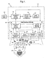
- FIG. 1 illustrates a vehicle navigation system 10.
- the vehicle navigation system 10 includes a processor-based system comprising a processor 12 configured to execute a number of software modules, including a vehicle position module 14, a navigation server module 16, and a user interface module 18.
- the processor 12 may interface with a user 20 via one or more input and output devices controlled by the user interface module 18.
- the user 20 can be the driver of the vehicle or, alternatively, a passenger.
- the processor 12 is typically configured to operate with one or more types of processor readable media.
- Processor readable media can be any available media that can be accessed by the processor 12 and includes both volatile and nonvolatile media, removable and non-removable media.
- processor readable media may include storage media and communication media.
- Storage media includes both volatile and nonvolatile, removable and nonremovable media implemented in any method or technology for storage of information such as processor-readable instructions, data structures, program modules, or other data.
- Storage media includes, but is not limited to, RAM, ROM, EEPROM, flash memory or other memory technology, CD-ROM, digital versatile discs (DVDs) or other optical disc storage, magnetic cassettes, magnetic tape, magnetic disk storage or other magnetic storage devices, or any other medium that can be used to store the desired information and that can be accessed by the processor 12.
- Communication media typically embodies processor-readable instructions, data structures, program modules or other data in a modulated data signal such as a carrier wave or other transport mechanism and includes any information delivery media.
- modulated data signal means a signal that has one or more of its characteristics set or changed in such a manner as to encode information in the signal.
- communication media includes wired media such as a wired network or direct-wired connection, and wireless media such as acoustic, RF, infrared, and other wireless media. Combinations of any of the above are also intended to be included within the scope of processor-readable media.
- the vehicle position module 14 determines the location of the vehicle, for example, by obtaining data from a GPS module 22. Alternatively, the vehicle position module 14 may determine the location of the vehicle in another way, such as by measuring the distance and direction traveled from a known reference point. In addition to the location of the vehicle, the vehicle position module 14 may also determine the direction of travel of the vehicle. The vehicle position module 14 may determine the direction of travel using any of a variety of conventional techniques.
- the vehicle position module 14 provides the location and direction of travel information to the navigation server module 16.
- the navigation server module 16 uses this information in combination with navigation data to determine where the vehicle is located relative to a route formed by a sequence of route segments.
- the navigation data may include, for example, map data, a list of turn maneuvers, or both, as well as other information pertinent to the route. Any or all of this information may be contained in a database 24.
- the database 24 may be stored in any of a variety of processor-readable media, including, for example, optical discs including CD-ROMs and DVD-ROMs, memory cards, and the like.
- the navigation server module 16 When the navigation server module 16 has identified the route segment on which the vehicle is located, the navigation server module 16 displays the identified route segment using a display screen 28 controlled via the user interface module 18.
- the display screen 26 is typically part of a vehicle information system, but may be implemented as a standalone display screen.
- the navigation server module 16 provides information regarding the route segment on which the vehicle is located to a navigation client module 28.
- the navigation client module 28 in turn generates graphic output, and may also generate audio output.
- the graphic output includes a representation of the route segment on which the vehicle is located and may also include a representation of the vehicle itself.
- a display driver 30 processes the graphic output and renders the graphic output on the display screen 26.
- the audio output may include speech, sound effects, or both. Speech output may be generated, for example, as a synthesized rendering of an identifier of the route segment by a text-to-speech module 32. Sound effects may include, for example, chimes or other sounds to alert the user 20 of events such as approaching within a threshold distance of a turn maneuver. Both speech and sound effects are processed by an audio driver 34, which renders the audio output using a speaker 36.
- the speaker 36 is typically part of a vehicle audio system, but may be implemented as a standalone speaker.
- the user interface module 18 can also receive input from the user 20. For example, the user 20 may "scroll" backward or forward through the sequence of route segments using a keypad 38, a knob 40, or other input device.
- An input interface 42 provides the input to the navigation client module 28, which makes appropriate changes to the display or audio output according to the input. Further, in some embodiments, the user 20 may interact with the vehicle navigation system 10 by voice commands spoken into a microphone 44.
- a voice recognition module 46 converts the voice commands to text or another format that can be processed by the vehicle navigation system 10.
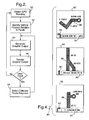
- FIG 2 is a flow diagram illustrating an example method executed by the processor 12 of Figure 1 to display a route comprising a sequence of route segments to be traveled by the vehicle.
- the vehicle position module 14 obtains from the GPS module 22 information relating to the position of the vehicle, including, for example, latitude and longitude readings (50). Based on the latitude and longitude readings and information received in the navigation server module 16 from the database 24, the processor 12 determines the position of the vehicle relative to the route (52). More particularly, the processor 12 identifies the particular route segment of the sequence of route segments on which the vehicle is currently located (52). While not required, the vehicle position module 14 may also determine a heading vector that indicates the direction in which the vehicle is traveling. The vehicle position module 14 may determine the heading vector using any of a variety of conventional techniques.
- the vehicle position module 14 may detect that the vehicle is off the prescribed route and notify the operator via an "off-route screen."
- the "off-route screen” may provide a direct line, or compass, heading vector and point-to-point distance to the desired location, or suggest that the user 20 make the appropriate maneuver or maneuvers to return to the prescribed route.
- the vehicle position module 14 may provide directions to the nearest known road or intersection, and from there generate a new list of directions to the desired destination. If the vehicle navigation system 10 is not operating in the active guidance mode, the vehicle navigation 10 provides no further information to the user 20 if the vehicle is off the prescribed route.
- the navigation server module 16 After identifying the route segment on which the vehicle is located, the navigation server module 16 executing on the processor 12 provides information regarding the route segment on which the vehicle is located to a navigation client module 28.
- the navigation client module 28 then generates graphic output (54), and, while not required, optionally also generates audio output.
- the graphic output includes a representation of the route segment on which the vehicle is located and may also include a representation of the vehicle itself. If included, the representation of the vehicle may be substantially centered relative to the display.
- the route segment is rendered in a north-up orientation, that is, with a top edge of the display corresponding to a north cardinal direction.
- the route segment may be rendered in a forward-up orientation such that the top edge of the display corresponds to a forward direction of travel as indicated by the heading vector.
- a display driver 30 processes the graphic output and renders the graphic output (56) on the display screen 26.
- the audio driver 32 may process the audio output and render the audio output via the speaker 26.
- the audio output may include speech, sound effects, or both.
- Speech output may include a synthesized rendering of an identifier of the route segment by the text-to-speech module 32.
- Sound effects may include, for example, chimes or other sounds to alert the user 20 of events such as approaching within a threshold distance of a turn maneuver.
- the user 20 may provide input to the processor 12 via the user interface module 18 executing on the processor 12.
- the user 20 may provide this input via, for example, the keypad 38, the knob 40, the microphone 44, or other input device.
- the processor 12 selects a different route segment of the sequence of route segments (58) as a function of the received input and generates graphic output (54) from the selected route segment.
- the graphic output is then rendered (56) on the display screen 26.
- the user input can cause the processor 12 to select a previous route segment or a subsequent route segment, or to return to the route segment on which the vehicle is currently located. For example, if the user 20 provides input via the knob 40, clockwise rotation of the knob 40 may cause the processor 12 to select the subsequent route segment for display. Conversely, counterclockwise rotation of the knob 40 may cause the processor 12 to select the previous route segment. In some embodiments, depressing the knob 40 causes the processor 12 to return to the route segment on which the vehicle is located.
- the user 20 may provide input via arrow or other keys on the keypad 38 or by using voice commands, such as "PREVIOUS SEGMENT,” “NEXT SEGMENT,” and “RETURN.” Accordingly, the user 20 can step through the sequence of route segments without needing to switch between different frames of reference.
- the processor 12 may also periodically update the route segment display based on movement of the vehicle. For example, even if the user 20 does not provide input, the processor 12 may periodically obtain updated GPS readings (50) and change the route segment display whenever the processor 12 determines that the vehicle has transitioned to a different route segment.
- Figure 3 illustrates an example route 70 that can be displayed by the vehicle navigation system 10.
- the route 70 includes a number of route segments, some of which are illustrated as route segments 72, 74, and 76.
- the route segment 72 corresponds to the beginning of the route at 82nd Street.
- the vehicle is currently located on the route segment 74, which corresponds to a junction between U.S. Highways 431 and 31.
- the route segments are defined relative to turn maneuvers, such as the exit on Lincoln Road. It will be appreciated, however, that the route segments can be defined relative to fixed distances.
- the relatively long stretch of U.S. Highway 31 may constitute multiple route segments.
- FIG 4 illustrates an example sequence 80 of graphic user interface (GUI) screens that may be presented to the user to display the route depicted in Figure 3.
- GUI graphic user interface
- the display screen 26 displays a GUI screen 82.
- the knob 40 By turning the knob 40 clockwise or providing other input, the user 20 can preview the remainder of the route by displaying the GUI screens 84 and 86, which correspond to route segments 74 and 76, respectively, in sequence.
- the display can automatically advance to the GUI screens 84 and 86 when the vehicle itself moves to the route segments 74 and 76.
- each GUI screen 82, 84, and 86 incorporates a number of common features.
- an arrowhead 88 or other symbol represents the vehicle.
- the arrowhead 88 is substantially centered with respect to the display area, with the representation of the route segment dynamically updated to reflect the current position of the vehicle relative to the route segment.
- the GUI screens can be displayed in either a north-up orientation or a forward-up orientation.
- the top edge of the display area corresponds to the north cardinal direction.
- the forward-up orientation the top edge of the display area corresponds to the forward direction of travel.
- Different users may prefer different orientations. Accordingly, in some embodiments, the user 20 can select a preferred orientation.
- Each GUI screen 82, 84, and 86 includes a legend 90 that identifies the route segment.
- the legend 90 identifies the route segment as the junction of U.S. Highways 431 and 31, heading north.
- the GUI screens may also include a directional indicator 92 to advise the user 20 to turn left or right or to continue in the current direction of travel.
- Major streets and their names may also be displayed.
- Minor streets, such as streets not forming part of the route, may either be displayed or omitted. Omitting minor streets from the display may make the display easier to use.
- the navigation system displays the route as a sequence of route segments rather than on an overview map or a combination of an overview map and detailed maps
- the user can easily step through the route using a simple control, such as a knob, keypad, or voice commands.
- a simple control such as a knob, keypad, or voice commands.
- the user can view the entire route easily without having to mentally adjust to different frames of reference, such as between an overview map and a detailed map.
Abstract
Description
- The disclosure relates generally to vehicle navigation systems. More particularly, the disclosure relates to graphic user interfaces for use in connection with vehicle navigation systems.
- An increasing number of vehicles are equipped with on-board navigation systems that display the position of the vehicle and surrounding streets, intersections, and other points of interest. Some navigation systems allow the driver to input or program a route. The navigation system then displays the position of the vehicle along the route.
- For many conventional vehicle navigation systems, the ability to display the entire route is limited by the size of the display and by the manner in which the map or route is displayed. The user can view the route either as a list of maneuvers or on a relatively large-scale overview map. When viewing the route as a list of maneuvers, the user may find it difficult to follow the entire list, particularly when the list includes many maneuvers and occupies several pages. On the other hand, when displaying the route on the overview map, the display may not show detailed information such as street names, particularly if the display is relatively small. The user must then "zoom in" on the map to see this detailed information. This more detailed view, however, displays a smaller area of the map. As a result, the user cannot see the entire route without "zooming out" to the overview map again. Interacting with the interface in this way requires the driver to mentally adjust to a different frame of reference, i.e., between the overview map and the detailed view, and can distract the driver.
- According to various example implementations, a vehicle navigation system displays a route formed by a sequence of route segments using a simple graphic user interface (GUI). More particularly, at any given time, the vehicle navigation system displays a single route segment. The route segment may be defined either as the distance between consecutive turn points or as a fixed distance. A graphic representation of the vehicle is also displayed. The user can scroll through the sequence of route segments using a simple control, such as a knob or a keypad.
- In one implementation, a route comprising a sequence of route segments to be traveled by a vehicle is displayed. A position of the vehicle is determined. A route segment on which the vehicle is located is then identified as a function of the position of the vehicle. The identified route segment is rendered using a graphic user interface (GUI). A different one of the route segments is rendered using the GUI in response to a user input.
- In another implementation, a route comprising a sequence of route segments to be traveled by a vehicle is displayed by displaying a graphic representation of the vehicle and a route segment on which the vehicle is located using a graphic user interface (GUI). A user input is received. A previous route segment or a subsequent route segment is displayed using the GUI in response to the user input.
- Another implementation is directed to a navigation system for use in a vehicle. The navigation system includes a display device and a global positioning system (GPS) receiver configured to determine a position of the vehicle. A data retrieval device is configured to retrieve navigation data from a data storage medium. The navigation data represents a sequence of route segments. A processor-based subsystem is operatively coupled to the GPS receiver, the data retrieval device, and the display device. The processor-based subsystem is configured to determine a position of the vehicle and identify a route segment on which the vehicle is located as a function of the position of the vehicle. The processor-based system is also configured to render the identified route segment using a graphic user interface (GUI) and to render a different one of the route segments using the GUI in response to a user input.
- Yet another implementation is directed to a navigation system for use in a vehicle. The navigation system includes a display device and an input device. A global positioning system (GPS) receiver is configured to determine a position of the vehicle. A data retrieval device is configured to retrieve navigation data from a data storage medium. The navigation data represents a sequence of route segments. A processor-based subsystem is operatively coupled to the GPS receiver, the data retrieval device, the display device, and the input device. The processor-based subsystem is configured to display a graphic representation of the vehicle and a route segment on which the vehicle is located using a graphic user interface (GUI) and to receive a user input using the input device. The processor-based subsystem is also configured to display one of a previous route segment and a subsequent route segment using the GUI in response to the user input.
- In another implementation, a processor-readable medium contains processor-executable instructions that, when executed by a processor-based system in a vehicle, cause the processor-based system to determine a position of the vehicle and to retrieve route information representing a route comprising a sequence of route segments. The processor-based system then identifies a route segment on which the vehicle is located as a function of the position of the vehicle. The identified route segment is rendered using a graphic user interface (GUI). A different one of the route segments is rendered using the GUI in response to a user input.
- In still another implementation, a processor-readable medium containing processor-executable instructions that, when executed by a processor-based system in a vehicle, cause the processor-based system to retrieve route information representing a route comprising a sequence of route segments. The processor-based system displays a graphic representation of the vehicle and a route segment on which the vehicle is located using a graphic user interface (GUI) and receives a user input. The processor-based system displays one of a previous route segment and a subsequent route segment using the GUI in response to the user input.
- Various implementations may provide certain advantages. The navigation system displays only a single route segment at a time. The user can scroll backward and forward through the sequence of route segments using a simple control. As a result, the user can view the entire route easily without having to mentally adjust to different frames of reference, such as between an overview map and a detailed map.
- Additional advantages and features will become apparent from the following description and the claims that follow, considered in conjunction with the accompanying drawings.
-
- Figure 1 is a block diagram depicting a vehicle navigation system according to an embodiment.
- Figure 2 is a flow diagram illustrating a method of displaying a route according to another embodiment.
- Figure 3 illustrates an example route comprising a sequence of route segments.
- Figure 4 illustrates an example sequence of graphic user interface (GUI) screens that may be presented to the user to display the route depicted in Figure 3.
-
- A vehicle navigation system uses a simple graphic user interface (GUI) to display a route formed by a sequence of route segments. At any given time, the vehicle navigation system displays a single route segment, defined either as the distance between consecutive turn points or as a fixed distance. The vehicle navigation system also displays a graphic representation of the vehicle. The user can scroll backward and forward through the sequence of route segments using a simple control, such as a knob or a keypad. As a result, the user can view the entire route easily without having to mentally adjust to different frames of reference, such as between an overview map and a detailed map.
- The following description of various embodiments implemented in a vehicle navigation system is to be construed by way of illustration rather than limitation. This description is not intended to limit the invention or its applications or uses. For example, while various embodiments are described as being implemented in a vehicle navigation system, it will be appreciated that the principles described herein may be applicable to navigation systems operable in other environments.
- In the following description, numerous specific details are set forth in order to provide a thorough understanding of various embodiments. It will be apparent to one skilled in the art that the present invention may be practiced without some or all of these specific details. In other instances, well known components and process steps have not been described in detail in order to avoid unnecessarily obscuring the present invention.
- Various embodiments may be described in the general context of processor-executable instructions, such as program modules, being executed by a processor. Generally, program modules include routines, programs, objects, components, data structures, etc., that perform particular tasks or implement particular abstract data types. In addition, some embodiments may also be practiced in distributed processing environments in which tasks are performed by remote processing devices that are linked through a communications network or other data transmission medium. In a distributed processing environment, program modules and other data may be located in both local and remote storage media, including memory storage devices.
- Referring now to the drawings, Figure 1 illustrates a
vehicle navigation system 10. Thevehicle navigation system 10 includes a processor-based system comprising aprocessor 12 configured to execute a number of software modules, including avehicle position module 14, anavigation server module 16, and auser interface module 18. As described below, theprocessor 12 may interface with auser 20 via one or more input and output devices controlled by theuser interface module 18. Theuser 20 can be the driver of the vehicle or, alternatively, a passenger. - The
processor 12 is typically configured to operate with one or more types of processor readable media. Processor readable media can be any available media that can be accessed by theprocessor 12 and includes both volatile and nonvolatile media, removable and non-removable media. By way of example, and not limitation, processor readable media may include storage media and communication media. Storage media includes both volatile and nonvolatile, removable and nonremovable media implemented in any method or technology for storage of information such as processor-readable instructions, data structures, program modules, or other data. Storage media includes, but is not limited to, RAM, ROM, EEPROM, flash memory or other memory technology, CD-ROM, digital versatile discs (DVDs) or other optical disc storage, magnetic cassettes, magnetic tape, magnetic disk storage or other magnetic storage devices, or any other medium that can be used to store the desired information and that can be accessed by theprocessor 12. Communication media typically embodies processor-readable instructions, data structures, program modules or other data in a modulated data signal such as a carrier wave or other transport mechanism and includes any information delivery media. The term "modulated data signal" means a signal that has one or more of its characteristics set or changed in such a manner as to encode information in the signal. By way of example, and not limitation, communication media includes wired media such as a wired network or direct-wired connection, and wireless media such as acoustic, RF, infrared, and other wireless media. Combinations of any of the above are also intended to be included within the scope of processor-readable media. - The
vehicle position module 14 determines the location of the vehicle, for example, by obtaining data from aGPS module 22. Alternatively, thevehicle position module 14 may determine the location of the vehicle in another way, such as by measuring the distance and direction traveled from a known reference point. In addition to the location of the vehicle, thevehicle position module 14 may also determine the direction of travel of the vehicle. Thevehicle position module 14 may determine the direction of travel using any of a variety of conventional techniques. - The
vehicle position module 14 provides the location and direction of travel information to thenavigation server module 16. Thenavigation server module 16 uses this information in combination with navigation data to determine where the vehicle is located relative to a route formed by a sequence of route segments. The navigation data may include, for example, map data, a list of turn maneuvers, or both, as well as other information pertinent to the route. Any or all of this information may be contained in adatabase 24. Thedatabase 24 may be stored in any of a variety of processor-readable media, including, for example, optical discs including CD-ROMs and DVD-ROMs, memory cards, and the like. - When the
navigation server module 16 has identified the route segment on which the vehicle is located, thenavigation server module 16 displays the identified route segment using adisplay screen 28 controlled via theuser interface module 18. Thedisplay screen 26 is typically part of a vehicle information system, but may be implemented as a standalone display screen. - In the embodiment shown in Figure 1, the
navigation server module 16 provides information regarding the route segment on which the vehicle is located to anavigation client module 28. Thenavigation client module 28 in turn generates graphic output, and may also generate audio output. The graphic output includes a representation of the route segment on which the vehicle is located and may also include a representation of the vehicle itself. Adisplay driver 30 processes the graphic output and renders the graphic output on thedisplay screen 26. The audio output may include speech, sound effects, or both. Speech output may be generated, for example, as a synthesized rendering of an identifier of the route segment by a text-to-speech module 32. Sound effects may include, for example, chimes or other sounds to alert theuser 20 of events such as approaching within a threshold distance of a turn maneuver. Both speech and sound effects are processed by anaudio driver 34, which renders the audio output using aspeaker 36. Thespeaker 36 is typically part of a vehicle audio system, but may be implemented as a standalone speaker. - In addition to providing output to the
user 20, theuser interface module 18 can also receive input from theuser 20. For example, theuser 20 may "scroll" backward or forward through the sequence of route segments using akeypad 38, aknob 40, or other input device. Aninput interface 42 provides the input to thenavigation client module 28, which makes appropriate changes to the display or audio output according to the input. Further, in some embodiments, theuser 20 may interact with thevehicle navigation system 10 by voice commands spoken into amicrophone 44. Avoice recognition module 46 converts the voice commands to text or another format that can be processed by thevehicle navigation system 10. - Figure 2 is a flow diagram illustrating an example method executed by the
processor 12 of Figure 1 to display a route comprising a sequence of route segments to be traveled by the vehicle. Thevehicle position module 14 obtains from theGPS module 22 information relating to the position of the vehicle, including, for example, latitude and longitude readings (50). Based on the latitude and longitude readings and information received in thenavigation server module 16 from thedatabase 24, theprocessor 12 determines the position of the vehicle relative to the route (52). More particularly, theprocessor 12 identifies the particular route segment of the sequence of route segments on which the vehicle is currently located (52). While not required, thevehicle position module 14 may also determine a heading vector that indicates the direction in which the vehicle is traveling. Thevehicle position module 14 may determine the heading vector using any of a variety of conventional techniques. If thevehicle navigation system 10 is operating in an active guidance mode, that is, the navigation system is providing instructions to theuser 20, and the vehicle is not on the prescribed route, thevehicle position module 14 may detect that the vehicle is off the prescribed route and notify the operator via an "off-route screen." The "off-route screen" may provide a direct line, or compass, heading vector and point-to-point distance to the desired location, or suggest that theuser 20 make the appropriate maneuver or maneuvers to return to the prescribed route. If directions to the prescribed route can not be generated, thevehicle position module 14 may provide directions to the nearest known road or intersection, and from there generate a new list of directions to the desired destination. If thevehicle navigation system 10 is not operating in the active guidance mode, thevehicle navigation 10 provides no further information to theuser 20 if the vehicle is off the prescribed route. - After identifying the route segment on which the vehicle is located, the
navigation server module 16 executing on theprocessor 12 provides information regarding the route segment on which the vehicle is located to anavigation client module 28. Thenavigation client module 28 then generates graphic output (54), and, while not required, optionally also generates audio output. The graphic output includes a representation of the route segment on which the vehicle is located and may also include a representation of the vehicle itself. If included, the representation of the vehicle may be substantially centered relative to the display. In some embodiments, the route segment is rendered in a north-up orientation, that is, with a top edge of the display corresponding to a north cardinal direction. As an alternative, the route segment may be rendered in a forward-up orientation such that the top edge of the display corresponds to a forward direction of travel as indicated by the heading vector. - A
display driver 30 processes the graphic output and renders the graphic output (56) on thedisplay screen 26. While not shown in Figure 2, theaudio driver 32 may process the audio output and render the audio output via thespeaker 26. The audio output may include speech, sound effects, or both. Speech output may include a synthesized rendering of an identifier of the route segment by the text-to-speech module 32. Sound effects may include, for example, chimes or other sounds to alert theuser 20 of events such as approaching within a threshold distance of a turn maneuver. - To scroll backward or forward through the sequence of route segments, the
user 20 may provide input to theprocessor 12 via theuser interface module 18 executing on theprocessor 12. Theuser 20 may provide this input via, for example, thekeypad 38, theknob 40, themicrophone 44, or other input device. When theuser interface module 18 receives input from theuser 20, theprocessor 12 selects a different route segment of the sequence of route segments (58) as a function of the received input and generates graphic output (54) from the selected route segment. The graphic output is then rendered (56) on thedisplay screen 26. - The user input can cause the
processor 12 to select a previous route segment or a subsequent route segment, or to return to the route segment on which the vehicle is currently located. For example, if theuser 20 provides input via theknob 40, clockwise rotation of theknob 40 may cause theprocessor 12 to select the subsequent route segment for display. Conversely, counterclockwise rotation of theknob 40 may cause theprocessor 12 to select the previous route segment. In some embodiments, depressing theknob 40 causes theprocessor 12 to return to the route segment on which the vehicle is located. Alternatively, theuser 20 may provide input via arrow or other keys on thekeypad 38 or by using voice commands, such as "PREVIOUS SEGMENT," "NEXT SEGMENT," and "RETURN." Accordingly, theuser 20 can step through the sequence of route segments without needing to switch between different frames of reference. - In addition to progressing through the sequence of route segments in response to user input, the
processor 12 may also periodically update the route segment display based on movement of the vehicle. For example, even if theuser 20 does not provide input, theprocessor 12 may periodically obtain updated GPS readings (50) and change the route segment display whenever theprocessor 12 determines that the vehicle has transitioned to a different route segment. - Figure 3 illustrates an
example route 70 that can be displayed by thevehicle navigation system 10. As shown in Figure 3, theroute 70 includes a number of route segments, some of which are illustrated asroute segments route segment 72 corresponds to the beginning of the route at 82nd Street. As indicated by anarrowhead 78, the vehicle is currently located on theroute segment 74, which corresponds to a junction between U.S. Highways 431 and 31. After traveling on U.S. Highway 31 according to the route, the vehicle will exit on Lincoln Road, as indicated by theroute segment 76. In the example illustrated in Figure 3, the route segments are defined relative to turn maneuvers, such as the exit on Lincoln Road. It will be appreciated, however, that the route segments can be defined relative to fixed distances. For example, in some embodiments, the relatively long stretch of U.S. Highway 31 may constitute multiple route segments. - Figure 4 illustrates an
example sequence 80 of graphic user interface (GUI) screens that may be presented to the user to display the route depicted in Figure 3. As the vehicle begins on theroute segment 72 of Figure 3, thedisplay screen 26 displays aGUI screen 82. By turning theknob 40 clockwise or providing other input, theuser 20 can preview the remainder of the route by displaying the GUI screens 84 and 86, which correspond to routesegments route segments - To preserve a common frame of reference across the GUI screens, each
GUI screen arrowhead 88 or other symbol represents the vehicle. Thearrowhead 88 is substantially centered with respect to the display area, with the representation of the route segment dynamically updated to reflect the current position of the vehicle relative to the route segment. - The GUI screens can be displayed in either a north-up orientation or a forward-up orientation. In the north-up orientation shown in Figure 4, the top edge of the display area corresponds to the north cardinal direction. By contrast, in the forward-up orientation, the top edge of the display area corresponds to the forward direction of travel. Different users may prefer different orientations. Accordingly, in some embodiments, the
user 20 can select a preferred orientation. - Each
GUI screen legend 90 that identifies the route segment. For example, in theGUI screen 84, thelegend 90 identifies the route segment as the junction of U.S. Highways 431 and 31, heading north. The GUI screens may also include adirectional indicator 92 to advise theuser 20 to turn left or right or to continue in the current direction of travel. Major streets and their names may also be displayed. Minor streets, such as streets not forming part of the route, may either be displayed or omitted. Omitting minor streets from the display may make the display easier to use. - As demonstrated by the foregoing discussion, various implementations may provide certain advantages. Because the navigation system displays the route as a sequence of route segments rather than on an overview map or a combination of an overview map and detailed maps, the user can easily step through the route using a simple control, such as a knob, keypad, or voice commands. As a result, the user can view the entire route easily without having to mentally adjust to different frames of reference, such as between an overview map and a detailed map.
- It will be understood by those who practice the invention and those skilled in the art that various modifications and improvements may be made without departing from the spirit and scope of the disclosed embodiments. The scope of protection afforded is to be determined solely by the claims and by the breadth of interpretation allowed by law.
Claims (19)
- A method to display a route comprising a sequence of route segments to be traveled by a vehicle, the method comprising:determining a position of the vehicle;identifying a route segment on which the vehicle is located as a function of the position of the vehicle;rendering the identified route segment using a graphic user interface (GUI); andrendering a different one of the route segments using the GUI in response to a user input.
- The method of claim 1, further comprising rendering a different one of the route segments using the GUI in response to movement of the vehicle.
- The method of claim 1, wherein the GUI comprises:a display area having a top edge; anda graphic representation of the vehicle rendered within the display area.
- The method of claim 3, wherein the graphic representation of the vehicle is substantially centered relative to the display area.
- The method of claim 3, wherein the top edge of the display area is associated with one of a north cardinal direction and a forward direction of travel.
- The method of claim 1, wherein rendering a different one of the route segments using the GUI in response to the user input comprises rendering at least one of a previous route segment and a subsequent route segment using the GUI.
- The method of claim 1, further comprising receiving the user input using at least one of a keypad, a knob, and an audio input device.
- A navigation system for use in a vehicle, the navigation system of the type including a display device and a global positioning system (GPS) receiver configured to determine a position of the vehicle, the navigation system characterized by:a data retrieval device configured to retrieve navigation data from a data storage medium, the navigation data representing a sequence of route segments; anda processor-based subsystem operatively coupled to the GPS receiver, the data retrieval device, and the display device and configured to determine a position of the vehicle;identify a route segment on which the vehicle is located as a function of the position of the vehicle;render the identified route segment using a graphic user interface (GUI); andrender a different one of the route segments using the GUI in response to a user input.
- The navigation system of claim 8, wherein the processor-based subsystem is further configured to render a different one of the route segments using the GUI in response to movement of the vehicle.
- The navigation system of claim 8, wherein the GUI comprises:a display area having a top edge; anda graphic representation of the vehicle rendered within the display area.
- The navigation system of claim 10, wherein the graphic representation of the vehicle is substantially centered relative to the display area.
- The navigation system of claim 10, wherein the top edge of the display area is associated with one of a north cardinal direction and a forward direction of travel.
- The navigation system of claim 8, wherein rendering a different one of the route segments using the GUI in response to the user input comprises rendering at least one of a previous route segment and a subsequent route segment using the GUI.
- The navigation system of claim 8, further comprising an input device, the input device comprising at least one of a keypad, a knob, and an audio input device.
- A processor-readable medium containing processor-executable instructions that, when executed by a processor-based system in a vehicle, cause the processor-based system to:retrieve route information representing a route comprising a sequence of route segments;display a graphic representation of the vehicle and a route segment on which the vehicle is located using a graphic user interface (GUI);receive a user input; anddisplay one of a previous route segment and a subsequent route segment using the GUI in response to the user input.
- The processor-readable medium of claim 15, wherein the processor-executable instructions, when executed by the processor-based system, further cause the processor-based system to update the displayed route segment in response to movement of the vehicle.
- The processor-readable medium of claim 15, wherein the GUI comprises a display area having a top edge.
- The processor-readable medium of claim 17, wherein the graphic representation of the vehicle is substantially centered relative to the display area.
- The processor-readable medium of claim 15, wherein the top edge of the display area is associated with one of a north cardinal direction and a forward direction of travel.
Applications Claiming Priority (2)
| Application Number | Priority Date | Filing Date | Title |
|---|---|---|---|
| US10/732,971 US20050131638A1 (en) | 2003-12-11 | 2003-12-11 | Route sequence viewing in navigation system |
| US732971 | 2003-12-11 |
Publications (1)
| Publication Number | Publication Date |
|---|---|
| EP1541969A1 true EP1541969A1 (en) | 2005-06-15 |
Family
ID=34523059
Family Applications (1)
| Application Number | Title | Priority Date | Filing Date |
|---|---|---|---|
| EP04078260A Withdrawn EP1541969A1 (en) | 2003-12-11 | 2004-12-01 | Route sequence viewing in navigation system |
Country Status (2)
| Country | Link |
|---|---|
| US (1) | US20050131638A1 (en) |
| EP (1) | EP1541969A1 (en) |
Cited By (2)
| Publication number | Priority date | Publication date | Assignee | Title |
|---|---|---|---|---|
| US7430473B2 (en) | 2004-10-01 | 2008-09-30 | Bose Corporation | Vehicle navigation display |
| US9243921B2 (en) | 2014-02-18 | 2016-01-26 | Google Inc. | Intuitive preview of upcoming navigational instructions |
Families Citing this family (6)
| Publication number | Priority date | Publication date | Assignee | Title |
|---|---|---|---|---|
| US8938052B2 (en) * | 2005-04-21 | 2015-01-20 | The Invention Science Fund I, Llc | Systems and methods for structured voice interaction facilitated by data channel |
| EP1879001B1 (en) * | 2006-07-10 | 2016-04-27 | Harman Becker Automotive Systems GmbH | Format description for a navigation database |
| DE102008021952A1 (en) * | 2008-02-11 | 2009-09-03 | Navigon Ag | Method for operating a navigation system |
| JP5203747B2 (en) * | 2008-02-27 | 2013-06-05 | アルパイン株式会社 | Navigation device |
| WO2017130704A1 (en) * | 2016-01-29 | 2017-08-03 | パナソニック インテレクチュアル プロパティ コーポレーション オブ アメリカ | Navigation terminal, navigation system, wearable terminal, navigation method and program |
| KR20190018243A (en) * | 2017-08-14 | 2019-02-22 | 라인 가부시키가이샤 | Method and system for navigation using video call |
Citations (4)
| Publication number | Priority date | Publication date | Assignee | Title |
|---|---|---|---|---|
| US5544060A (en) * | 1991-10-16 | 1996-08-06 | Zexel Usa Corporation | Vehicle mounted navigation system with preview function |
| US5832406A (en) * | 1994-09-16 | 1998-11-03 | Alpine Electronics, Inc. | Vehicle navigation apparatus and method for route finding at road crossings |
| US6314369B1 (en) * | 1998-07-02 | 2001-11-06 | Kabushikikaisha Equos Research | Communications navigation system, and navigation base apparatus and navigation apparatus both used in the navigation system |
| EP1229305A1 (en) * | 2000-08-04 | 2002-08-07 | Matsushita Electric Industrial Co., Ltd | Route guide information generator, route guide information generating method, and navigation system |
Family Cites Families (1)
| Publication number | Priority date | Publication date | Assignee | Title |
|---|---|---|---|---|
| DE3475842D1 (en) * | 1984-07-27 | 1989-02-02 | De Villeroche Gerard Jodon | Electronic information and navigation system for traffic |
-
2003
- 2003-12-11 US US10/732,971 patent/US20050131638A1/en not_active Abandoned
-
2004
- 2004-12-01 EP EP04078260A patent/EP1541969A1/en not_active Withdrawn
Patent Citations (4)
| Publication number | Priority date | Publication date | Assignee | Title |
|---|---|---|---|---|
| US5544060A (en) * | 1991-10-16 | 1996-08-06 | Zexel Usa Corporation | Vehicle mounted navigation system with preview function |
| US5832406A (en) * | 1994-09-16 | 1998-11-03 | Alpine Electronics, Inc. | Vehicle navigation apparatus and method for route finding at road crossings |
| US6314369B1 (en) * | 1998-07-02 | 2001-11-06 | Kabushikikaisha Equos Research | Communications navigation system, and navigation base apparatus and navigation apparatus both used in the navigation system |
| EP1229305A1 (en) * | 2000-08-04 | 2002-08-07 | Matsushita Electric Industrial Co., Ltd | Route guide information generator, route guide information generating method, and navigation system |
Cited By (2)
| Publication number | Priority date | Publication date | Assignee | Title |
|---|---|---|---|---|
| US7430473B2 (en) | 2004-10-01 | 2008-09-30 | Bose Corporation | Vehicle navigation display |
| US9243921B2 (en) | 2014-02-18 | 2016-01-26 | Google Inc. | Intuitive preview of upcoming navigational instructions |
Also Published As
| Publication number | Publication date |
|---|---|
| US20050131638A1 (en) | 2005-06-16 |
Similar Documents
| Publication | Publication Date | Title |
|---|---|---|
| EP1566612B1 (en) | Previewing points of interest in navigation system | |
| US6529822B1 (en) | Navigation system with zoomed maneuver instruction | |
| US7135961B1 (en) | Method and system for providing directions for driving | |
| US6298305B1 (en) | Methods and apparatus for providing voice guidance in a vehicle navigation system | |
| EP1254349B1 (en) | A navigation system with unique audio tones for maneuver notification | |
| EP1528364B1 (en) | Device, system and method for reporting a traffic condition. | |
| JP5385506B2 (en) | Storage and visualization of target points in navigation systems | |
| US8515664B2 (en) | Digital map signpost system | |
| US9476727B2 (en) | Method and apparatus for predicting destinations | |
| US20050027437A1 (en) | Device, system, method and program for notifying traffic condition and recording medium storing the program | |
| US7039520B2 (en) | Method for operating a navigation system for a vehicle and corresponding navigation system | |
| US20100324818A1 (en) | Presentation of navigation instructions using variable content, context and/or formatting | |
| EP1078222A1 (en) | Method for displaying a current vehicle location using a navigation system | |
| US20100077359A1 (en) | Map display device | |
| US20050278115A1 (en) | Navigation apparatus and map-indication control program | |
| EP1541969A1 (en) | Route sequence viewing in navigation system | |
| US20100070166A1 (en) | Routing in mapping systems | |
| JP2005127887A (en) | On-vehicle navigation device, and route traffic information providing method | |
| EP2045578B1 (en) | Dynamic route guidance apparatus and method | |
| JP3353472B2 (en) | Road information display device | |
| US20060152386A1 (en) | Nagivation apparatus | |
| JP3350257B2 (en) | Travel position display device | |
| JP2000298026A (en) | Car navigation system | |
| JP2009180591A (en) | Map display device | |
| JP2009210529A (en) | Map display device |
Legal Events
| Date | Code | Title | Description |
|---|---|---|---|
| PUAI | Public reference made under article 153(3) epc to a published international application that has entered the european phase |
Free format text: ORIGINAL CODE: 0009012 |
|
| AK | Designated contracting states |
Kind code of ref document: A1 Designated state(s): AT BE BG CH CY CZ DE DK EE ES FI FR GB GR HU IE IS IT LI LT LU MC NL PL PT RO SE SI SK TR |
|
| AX | Request for extension of the european patent |
Extension state: AL BA HR LV MK YU |
|
| 17P | Request for examination filed |
Effective date: 20051215 |
|
| AKX | Designation fees paid |
Designated state(s): AT BE BG CH CY CZ DE DK EE ES FI FR GB GR HU IE IS IT LI LT LU MC NL PL PT RO SE SI SK TR |
|
| 17Q | First examination report despatched |
Effective date: 20061123 |
|
| STAA | Information on the status of an ep patent application or granted ep patent |
Free format text: STATUS: THE APPLICATION IS DEEMED TO BE WITHDRAWN |
|
| 18D | Application deemed to be withdrawn |
Effective date: 20090324 |