EP1543918A2 - Holding Device for Gas Turbine Rotor Blades and Machine Tool incorporating such a device - Google Patents
Holding Device for Gas Turbine Rotor Blades and Machine Tool incorporating such a device Download PDFInfo
- Publication number
- EP1543918A2 EP1543918A2 EP04257658A EP04257658A EP1543918A2 EP 1543918 A2 EP1543918 A2 EP 1543918A2 EP 04257658 A EP04257658 A EP 04257658A EP 04257658 A EP04257658 A EP 04257658A EP 1543918 A2 EP1543918 A2 EP 1543918A2
- Authority
- EP
- European Patent Office
- Prior art keywords
- dovetail
- retainers
- assembly
- rotor
- profile
- Prior art date
- Legal status (The legal status is an assumption and is not a legal conclusion. Google has not performed a legal analysis and makes no representation as to the accuracy of the status listed.)
- Withdrawn
Links
Images


Classifications
-
- B—PERFORMING OPERATIONS; TRANSPORTING
- B25—HAND TOOLS; PORTABLE POWER-DRIVEN TOOLS; MANIPULATORS
- B25B—TOOLS OR BENCH DEVICES NOT OTHERWISE PROVIDED FOR, FOR FASTENING, CONNECTING, DISENGAGING OR HOLDING
- B25B5/00—Clamps
- B25B5/14—Clamps for work of special profile
-
- B—PERFORMING OPERATIONS; TRANSPORTING
- B23—MACHINE TOOLS; METAL-WORKING NOT OTHERWISE PROVIDED FOR
- B23Q—DETAILS, COMPONENTS, OR ACCESSORIES FOR MACHINE TOOLS, e.g. ARRANGEMENTS FOR COPYING OR CONTROLLING; MACHINE TOOLS IN GENERAL CHARACTERISED BY THE CONSTRUCTION OF PARTICULAR DETAILS OR COMPONENTS; COMBINATIONS OR ASSOCIATIONS OF METAL-WORKING MACHINES, NOT DIRECTED TO A PARTICULAR RESULT
- B23Q3/00—Devices holding, supporting, or positioning work or tools, of a kind normally removable from the machine
- B23Q3/02—Devices holding, supporting, or positioning work or tools, of a kind normally removable from the machine for mounting on a work-table, tool-slide, or analogous part
- B23Q3/06—Work-clamping means
- B23Q3/062—Work-clamping means adapted for holding workpieces having a special form or being made from a special material
- B23Q3/063—Work-clamping means adapted for holding workpieces having a special form or being made from a special material for holding turbine blades
-
- B—PERFORMING OPERATIONS; TRANSPORTING
- B24—GRINDING; POLISHING
- B24B—MACHINES, DEVICES, OR PROCESSES FOR GRINDING OR POLISHING; DRESSING OR CONDITIONING OF ABRADING SURFACES; FEEDING OF GRINDING, POLISHING, OR LAPPING AGENTS
- B24B19/00—Single-purpose machines or devices for particular grinding operations not covered by any other main group
- B24B19/14—Single-purpose machines or devices for particular grinding operations not covered by any other main group for grinding turbine blades, propeller blades or the like
-
- B—PERFORMING OPERATIONS; TRANSPORTING
- B24—GRINDING; POLISHING
- B24B—MACHINES, DEVICES, OR PROCESSES FOR GRINDING OR POLISHING; DRESSING OR CONDITIONING OF ABRADING SURFACES; FEEDING OF GRINDING, POLISHING, OR LAPPING AGENTS
- B24B41/00—Component parts such as frames, beds, carriages, headstocks
- B24B41/06—Work supports, e.g. adjustable steadies
-
- F—MECHANICAL ENGINEERING; LIGHTING; HEATING; WEAPONS; BLASTING
- F01—MACHINES OR ENGINES IN GENERAL; ENGINE PLANTS IN GENERAL; STEAM ENGINES
- F01D—NON-POSITIVE DISPLACEMENT MACHINES OR ENGINES, e.g. STEAM TURBINES
- F01D25/00—Component parts, details, or accessories, not provided for in, or of interest apart from, other groups
- F01D25/28—Supporting or mounting arrangements, e.g. for turbine casing
- F01D25/285—Temporary support structures, e.g. for testing, assembling, installing, repairing; Assembly methods using such structures
-
- F—MECHANICAL ENGINEERING; LIGHTING; HEATING; WEAPONS; BLASTING
- F05—INDEXING SCHEMES RELATING TO ENGINES OR PUMPS IN VARIOUS SUBCLASSES OF CLASSES F01-F04
- F05D—INDEXING SCHEME FOR ASPECTS RELATING TO NON-POSITIVE-DISPLACEMENT MACHINES OR ENGINES, GAS-TURBINES OR JET-PROPULSION PLANTS
- F05D2230/00—Manufacture
- F05D2230/10—Manufacture by removing material
- F05D2230/14—Micromachining
-
- F—MECHANICAL ENGINEERING; LIGHTING; HEATING; WEAPONS; BLASTING
- F05—INDEXING SCHEMES RELATING TO ENGINES OR PUMPS IN VARIOUS SUBCLASSES OF CLASSES F01-F04
- F05D—INDEXING SCHEME FOR ASPECTS RELATING TO NON-POSITIVE-DISPLACEMENT MACHINES OR ENGINES, GAS-TURBINES OR JET-PROPULSION PLANTS
- F05D2240/00—Components
- F05D2240/55—Seals
-
- F—MECHANICAL ENGINEERING; LIGHTING; HEATING; WEAPONS; BLASTING
- F05—INDEXING SCHEMES RELATING TO ENGINES OR PUMPS IN VARIOUS SUBCLASSES OF CLASSES F01-F04
- F05D—INDEXING SCHEME FOR ASPECTS RELATING TO NON-POSITIVE-DISPLACEMENT MACHINES OR ENGINES, GAS-TURBINES OR JET-PROPULSION PLANTS
- F05D2250/00—Geometry
- F05D2250/10—Two-dimensional
- F05D2250/19—Two-dimensional machined; miscellaneous
- F05D2250/193—Two-dimensional machined; miscellaneous milled
-
- Y—GENERAL TAGGING OF NEW TECHNOLOGICAL DEVELOPMENTS; GENERAL TAGGING OF CROSS-SECTIONAL TECHNOLOGIES SPANNING OVER SEVERAL SECTIONS OF THE IPC; TECHNICAL SUBJECTS COVERED BY FORMER USPC CROSS-REFERENCE ART COLLECTIONS [XRACs] AND DIGESTS
- Y10—TECHNICAL SUBJECTS COVERED BY FORMER USPC
- Y10S—TECHNICAL SUBJECTS COVERED BY FORMER USPC CROSS-REFERENCE ART COLLECTIONS [XRACs] AND DIGESTS
- Y10S269/00—Work holders
- Y10S269/909—Work holder for specific work
-
- Y—GENERAL TAGGING OF NEW TECHNOLOGICAL DEVELOPMENTS; GENERAL TAGGING OF CROSS-SECTIONAL TECHNOLOGIES SPANNING OVER SEVERAL SECTIONS OF THE IPC; TECHNICAL SUBJECTS COVERED BY FORMER USPC CROSS-REFERENCE ART COLLECTIONS [XRACs] AND DIGESTS
- Y10—TECHNICAL SUBJECTS COVERED BY FORMER USPC
- Y10T—TECHNICAL SUBJECTS COVERED BY FORMER US CLASSIFICATION
- Y10T29/00—Metal working
- Y10T29/49—Method of mechanical manufacture
- Y10T29/49316—Impeller making
- Y10T29/4932—Turbomachine making
- Y10T29/49325—Shaping integrally bladed rotor
-
- Y—GENERAL TAGGING OF NEW TECHNOLOGICAL DEVELOPMENTS; GENERAL TAGGING OF CROSS-SECTIONAL TECHNOLOGIES SPANNING OVER SEVERAL SECTIONS OF THE IPC; TECHNICAL SUBJECTS COVERED BY FORMER USPC CROSS-REFERENCE ART COLLECTIONS [XRACs] AND DIGESTS
- Y10—TECHNICAL SUBJECTS COVERED BY FORMER USPC
- Y10T—TECHNICAL SUBJECTS COVERED BY FORMER US CLASSIFICATION
- Y10T29/00—Metal working
- Y10T29/49—Method of mechanical manufacture
- Y10T29/49316—Impeller making
- Y10T29/49336—Blade making
-
- Y—GENERAL TAGGING OF NEW TECHNOLOGICAL DEVELOPMENTS; GENERAL TAGGING OF CROSS-SECTIONAL TECHNOLOGIES SPANNING OVER SEVERAL SECTIONS OF THE IPC; TECHNICAL SUBJECTS COVERED BY FORMER USPC CROSS-REFERENCE ART COLLECTIONS [XRACs] AND DIGESTS
- Y10—TECHNICAL SUBJECTS COVERED BY FORMER USPC
- Y10T—TECHNICAL SUBJECTS COVERED BY FORMER US CLASSIFICATION
- Y10T29/00—Metal working
- Y10T29/49—Method of mechanical manufacture
- Y10T29/49998—Work holding
-
- Y—GENERAL TAGGING OF NEW TECHNOLOGICAL DEVELOPMENTS; GENERAL TAGGING OF CROSS-SECTIONAL TECHNOLOGIES SPANNING OVER SEVERAL SECTIONS OF THE IPC; TECHNICAL SUBJECTS COVERED BY FORMER USPC CROSS-REFERENCE ART COLLECTIONS [XRACs] AND DIGESTS
- Y10—TECHNICAL SUBJECTS COVERED BY FORMER USPC
- Y10T—TECHNICAL SUBJECTS COVERED BY FORMER US CLASSIFICATION
- Y10T29/00—Metal working
- Y10T29/51—Plural diverse manufacturing apparatus including means for metal shaping or assembling
-
- Y—GENERAL TAGGING OF NEW TECHNOLOGICAL DEVELOPMENTS; GENERAL TAGGING OF CROSS-SECTIONAL TECHNOLOGIES SPANNING OVER SEVERAL SECTIONS OF THE IPC; TECHNICAL SUBJECTS COVERED BY FORMER USPC CROSS-REFERENCE ART COLLECTIONS [XRACs] AND DIGESTS
- Y10—TECHNICAL SUBJECTS COVERED BY FORMER USPC
- Y10T—TECHNICAL SUBJECTS COVERED BY FORMER US CLASSIFICATION
- Y10T409/00—Gear cutting, milling, or planing
- Y10T409/30—Milling
- Y10T409/303752—Process
- Y10T409/303808—Process including infeeding
Definitions
- This invention relates generally to gas turbine engines, and more specifically to methods and apparatus for machining gas turbine engine components.
- Accurate manufacturing of a component may be a significant factor in determining a fabricating time of the component.
- accurate manufacturing of the blade may be one of the most significant factors affecting an overall cost of fabrication of the gas turbine engine, as well as subsequent modifications, repairs, and inspections of the blade.
- at least some known gas turbine engines include a compressor for compressing air which is mixed with a fuel and channeled to a combustor wherein the mixture is ignited within a combustion chamber for generating hot combustion gases.
- At least some known compressors include a rotor assembly that includes at least one row of circumferentially spaced rotor blades.
- Each rotor blade includes an airfoil that includes a pressure side, and a suction side connected together at leading and trailing edges. Each airfoil extends radially outward from a rotor blade platform. Each rotor blade also includes a dovetail that extends radially inward from a shank coupled to the platform. The dovetail is used to mount the rotor blade within the rotor assembly to a rotor disk or spool.
- a pressure differential is created between the compressor blade pressure side and the compressor blade suction side which may result in an undesirable leakage flow between the upstream and downstream portions of the rotor.
- One such possible leakage path may form at an interconnection between each rotor blade and the rotor disk, where a gap may be defined between a blade base member, usually a dovetail design, and a rotor disk groove in which the rotor blades are carried. Accordingly, in at least some gas turbine engines small diameter seal wires are inserted between the blade platform and the outer periphery of the rotor disk to facilitate sealing the upstream and downstream areas at the interconnection formed between each rotor blade and the rotor disk.
- seal wires are split and as such, may expand in a radial direction when subjected to centrifugal force. Seal wires facilitate minimizing leakage gas flow from the high-pressure region of the flow path to the low-pressure region, and thereby maintain the maximum mass flow of the gas flow stream to maintain the operating efficiency of the engine.
- At least some known methods of fabricating a seal wire groove include fabricating a machining assembly that includes a plurality of individual components permanently coupled, for example by bolting the components to the assembly, to enable a groove to be machined in a specific set of compressor blades. For example, during fabrication, the machining assembly is installed in a milling machine and a plurality of test cuts are performed on the blade to verify the alignement of the retainers. The seal wire groove is then machined into the compressor blades. The machining assembly is then removed from the milling machine and the individual components are then unbolted from the machining assembly and a second set of components is bolted.
- the machining assembly is then re-installed in the milling machine and a plurality of test cuts are performed on the blade to verify that the machining assembly is properly aligned for the second time.
- a seal wire groove is then machined into a second set of compressor blades installed on a second compressor rotor section. This process is repeated until all the compressor blades for each compressor rotor section have been machined.
- Removing the machining assembly from the milling machine and re-installing separate components for each set of compressor blades is a relatively labor intensive process since each holding fixture must be installed on the milling machine prior to cutting the seal wire groove in the next set of blades. Additionally, an increased quantity of milling cutters are used to perform the test cuts and to machine the seal wire groove. Since the method for cutting a seal wire groove is relatively complex, at least one known manufacturer machines a plurality of seal grooves without changing the holding fixture to faciliate reducing costs of fabrication. Accordingly, the manufacturer may often produce a quantity of blades that is in excess of the quantity desired by the customer.
- a method of using a machining assembly to machine a plurality of different turbine components that include a dovetail having a contoured profile includes removably coupling a first set of retainers into the machining assembly, the first set of retainers include an upper portion having a profile that substantially mirrors a portion of the first dovetail, and a lower portion having a profile that substantially mirrors an opposite side of the first dovetail, coupling a first turbine component between the upper and lower portions such that the first turbine component is secured by the first set of retainers, coupling the machining assembly into a milling machine, and machining at least one seal groove into the dovetail of the first turbine component.
- an assembly for machining a seal wire groove into a gas turbine rotor blade that includes a dovetail includes a base portion, a body portion coupled to the base portion, and a first set of retainers removably coupled to the body portion, the first set of retainers including an upper portion having a profile that substantially mirrors a portion of the first dovetail, and a lower portion having a profile that substantially mirrors an opposite side of the first dovetail.
- a milling machine in a further aspect, includes an assembly for machining a seal wire groove into a gas turbine rotor blade that includes a dovetail.
- the assembly includes a base portion, a body portion coupled to the base portion, and a first set of retainers removably coupled to the body portion, the first set of retainers including an upper portion having a profile that substantially mirrors a portion of the first dovetail, and a lower portion having a profile that substantially mirrors an opposite side of the first dovetail, and a grinding wheel configured to machine at least one seal wire groove into the dovetail.
- the terms “manufacture” and “manufacturing” may include any manufacturing process.
- manufacturing processes may include grinding, finishing, polishing, cutting, machining, inspecting, and/or casting.
- the above examples are intended as exemplary only, and thus are not intended to limit in any way the definition and/or meaning of the terms “manufacture” and “manufacturing”.
- the term “component” may include any object to which a manufacturing process is applied.
- the invention is described herein in association with a gas turbine engine, and more specifically for use with a compressor blade for a gas turbine engine, it should be understood that the present invention may be applicable to any component and/or any manufacturing process. Accordingly, practice of the present invention is not limited to the manufacture of compressor blades or other components of gas turbine engines.
- Figure 1 is a schematic illustration of a gas turbine engine 10 having a longitudinal axis 11, and including a core gas turbine engine 12 and a fan section 14 positioned upstream of core engine 12.
- Core engine 12 includes a generally tubular outer casing 16 that defines an annular core engine inlet 18.
- Casing 16 surrounds a low-pressure booster 20 for raising the pressure of the incoming air to a first pressure level.
- engine 10 is a CFM56 engine available from General Electric Aircraft Engines, Cincinnati, Ohio.
- a high pressure, multi-stage, axial-flow compressor 22 receives pressurized air from booster 20 and further increases the pressure of the air to a second, higher pressure level.
- the high pressure air flows to a combustor 24 and is mixed with fuel.
- the fuel-air mixture is ignited to raise the temperature and energy level of the pressurized air.
- the high energy combustion products flow to a first turbine 26 for driving compressor 22 through a first drive shaft 28, and then to a second turbine 30 for driving booster 20 through a second drive shaft 32 that is coaxial with first drive shaft 28. After driving each of turbines 26 and 30, the combustion products leave core engine 12 through an exhaust nozzle 34 to provide propulsive jet thrust.
- Fan section 14 includes a rotatable, axial-flow fan rotor 36 that is driven by second turbine 30.
- An annular fan casing 38 surrounds fan rotor 36 and is supported from core engine 12 by a plurality of substantially radially-extending, circumferentially-spaced support struts 44.
- Fan rotor 36 carries a plurality of radially-extending, circumferentially spaced fan blades 42.
- Fan casing 38 extends rearwardly from fan rotor 36 over an outer portion of core engine 12 to define a secondary, or bypass airflow conduit.
- a casing element 39 that is downstream of and connected with fan casing 38 supports a plurality of fan stream outlet guide vanes 40. The air that passes through fan section 14 is propelled in a downstream direction by fan blades 42 to provide additional propulsive thrust to supplement the thrust provided by core engine 12.
- FIG 2 is a cross-sectional view of a portion of a compressor 50 that may be used with core gas turbine 12 (shown in Figure 1).
- compressor 50 includes nine stages 45, wherein each stage 46 includes an array of radially-extending, circumferentially-spaced stator vanes 47 and a plurality of peripherally-carried, radially-extending, circumferentially-spaced rotor blades 48.
- Inlet guide vanes 51 and stator vanes 52 of stages one through three of compressor 50 are variable in that they are pivotable about an axis that extends radially relative to the compressor axis of rotation.
- Stator vanes 54 of stages four through eight and outlet guide vanes 55 are fixed in position.
- the respective rotor disks 56 include a series of peripherally-spaced, axially-extending dovetail slots 49 into which rotor blades 58 are inserted and from which rotor blades 58 are removed in an axial direction.
- Compressor 50 includes an inlet 66 that defines a flow passageway 67 having a relatively large flow area, and an outlet 68 that defines a relatively smaller area flow passageway 69 through which the compressed air passes.
- An outer boundary of the flow passageway is defined by an outer annular casing 70 and an inner boundary of the flow passageway is defined by the blade platforms of respective blades 58, 64 carried by rotors 56, 60, and also by a stationary annular seal ring 72 that is carried at an inner periphery of each of the respective stator sections 52, 54.
- respective rotor disks 56, 60 are ganged together by a suitable disk-to-disk coupling arrangement (not shown), and the third stage disk is connected with a drive shaft 74 that is operatively connected with a turbine rotor (not shown).
- Each stator section 52, 54 includes an annular abradable seal that is carried by a respective annular sealing ring 72 and that is adapted to be engaged by respective labyrinth seals carried by 56, 60 in order to minimize air leakage around the respective stators 52, 54.
- Sealing rings 72 also serve to confine the flow of air to the flow passageway defined by outer casing 70 and the radially innermost surfaces of the respective stator vanes 47.
- FIG. 3 is an end view of a rotor blade 64 coupled to rotor disk 60.
- Rotor disk 60 includes a plate-like disk body 76 that terminates in an enlarged outer rim 78.
- Outer rim 78 includes a forward axial ring 80 and an aft axial ring 82 that each extend in a generally axial direction of engine 10 to engage with corresponding forward and aft axial rings 80, 82 of adjacent rotor disks 60 to provide a direct, driving interconnection between the respective rotor disks 56, 60 so that they all rotate together.
- Outer rim 78 also includes a rotor-blade-receiving circumferential slot 84 that in the exemplary embodiment is substantially U-shaped.
- Slot 84 has a cross-sectional form of a dovetail, and includes a slot base 86.
- Slot 84 is defined by a forward sidewall 88 and an aft sidewall 90 that are spaced axially from each other and that extend in a generally radial direction.
- Each of forward and aft sidewalls 88, 90 has a respective inward convex projection 92, 94 that defines a generally dovetail-type shape of slot 84.
- each slot sidewall 88, 90 includes a radially-extending flange 96, 98.
- seal wire groove 100, 102 sized to receive a respective seal wire 104, 106 that has a substantially circular cross-section.
- seal wire 104, 106 has a substantially non-circular cross-section. Seal wires 104, 106 are split and have a predetermined length (not shown) such that they extend substantially circumferentially within seal wire grooves 100, 102.
- each groove 100, 102 is selected to enable wires 104, 106 to be slidably received therein, and each groove 100, 102 has a depth in the radial direction that is at least as deep as diameter of each seal wire 104, 106.
- Rotor blade 64 includes a base member 108 that has a shape that corresponds substantially with that of circumferential slot 84.
- Base member 108 as shown is in the form of a dovetail and includes an enlarged base portion 110 that is received in lateral recesses 112, 114 formed in rotor slot 84.
- Base member 108 also includes a recessed portion 116, 118 on each side to receive the inwardly-extending convex projections 92, 94 of rotor slot 84.
- a blade platform 120 is carried on base member 108 and extends in a generally transverse direction relative to the longitudinal axis of base member 108.
- Platform 120 Extending longitudinally from upper surface 119 of blade platform 120, and in a direction opposite to that of base member 108, is an airfoil portion 122, which is adapted to contact the gases that pass through engine 10.
- Platform 120 also includes a pair of axially-spaced lower surfaces 132, 134 each having a respective concave recess 138, 140 respectively, that is axially aligned with corresponding disk groves 100, 102 to receive and to engage with respective seal wires 104, 106.
- Concave recesses 138, 140 are configured to facilitate surface-to-surface contact between blade platform 120 and seal wires 104, 106, rather than line contact therebetween, thereby reducing the localized compressive stresses to which forward and aft blade platform lower faces 132, 134 are subjected during engine operation.
- Blade platform 120 terminates at a forward axial extension 128 and at an aft axial extension 130 that each overlie a respective forward and aft radial flange 96, 98 carried by rotor disk 60.
- Seal wires 104, 106 contact the respective platform lower faces 132, 134???, and also contact a portion of respective seal wire grooves 100, 102 formed in rotor disk 60.
- seal wires 104, 106 contact the respective platform lower faces 132, 134???, and also contact a portion of respective seal wire grooves 100, 102 formed in rotor disk 60.
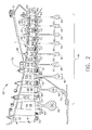
- Figure 4 is a machining assembly 200 that may be used to machine wire seal grooves in a rotor blade such as blade 64 (shown in Figure 3).
- Figure 5 is a perspective view of a portion of machining assembly 200.
- Machining assembly 200 includes a base portion 202, a body portion 204 coupled to base portion 202, and a first set of retainers 206 slidably coupled to base portion 202.
- Body portion 204 also includes a locking mechanism 207 that is coupled to body portion 204, a first opening 208, and a second opening 209.
- Locking mechanism 208 includes a first end 210, a second end 212, and a central portion 214 that couples first end 210 to second end 212.
- Locking mechanism 207 also includes a handle 216 coupled to second end 212.
- each set of retainers 206 includes an upper portion 220 and a lower portion 222.
- Upper portion 220 includes a first end 224, a second end 226, and a locking mechanism 228.
- First end 224 has a cross-sectional profile 230 defined by a plurality of external surfaces 232.
- first end 224 has a substantially rectangular cross-sectional geometric profile that is substantially similar to a cross-sectional profile of opening 208.
- Second end 226 includes a retaining portion 234.
- retaining portion 234 has cross-sectional profile that is substantially equivalent to a cross-sectional profile of a blade upper surface 236.
- Lower portion 222 includes a first end 240 and a second end 242.
- First end 240 and second end 242 each having a cross-sectional profile 244 defined by a plurality of external surfaces 246.
- first end 240 and second end 242 each have a substantially T-shaped cross-sectional profile 244 that is substantially similar to a cross-sectional profile of opening 209.
- Lower portion 222 also includes a lower second portion 248 extending from second end 242.
- Lower second portion 248 includes a retaining portion 250 that has a cross-sectional profile that is substantially equivalent to, i.e., mirrors, a cross-sectional profile of a blade lower surface 252.
- Figure 6 is a perspective view of a portion of machining assembly 200 (shown in Figure 4) including a second set of retainers 300.
- Retainers 300 are substantially similar to retainers 206, (shown in Figure 5) and components of retainers 206 that are identical to components of retainers 300 are identified in Figure 6 using the same reference numerals used in Figure 5.
- Retainers 300 include an upper portion 320 and a lower portion 322.
- Upper portion 220 includes a first end 224, a second end 226, and a locking mechanism 228.
- First end 224 has a cross-sectional profile 230 defined by a plurality of external surfaces 232.
- first end 224 has a substantially rectangular cross-sectional geometric profile.
- Second end 226 includes a retaining portion 334.
- retaining portion 334 has cross-sectional profile that is substantially equivalent to a cross-sectional profile of a blade upper surface 336.
- Lower portion 222 includes a first end 240 and a second end 242.
- First end 240 and second end 242 each have a cross-sectional profile 244 defined by a plurality of external surfaces 246.
- first end 240 and second end 242 each have a substantially T-shaped cross-sectional profile 244.
- Lower portion 222 also includes a lower second portion 248 extending from second end 242.
- Lower second portion 248 includes a retaining portion 350 that has a cross-sectional profile that is substantially equivalent to a cross-sectional profile of a blade lower surface 352.
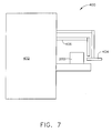
- FIG 7 is a side view of an exemplary milling system 400 that may be used with machining assembly 200 (shown in Figure 4).
- Milling system 400 includes a milling machine 402, and a grinding wheel 404 for use with milling system 400.
- grinding wheel 404 is fabricated from a cubic boron nitride (CBN) material.
- a coolant passage 406 extends from milling machine 402 such that a coolant, passing through coolant passage 406 is applied to a rotor blade, positioned within machining assembly 200, during milling operation.
- machining assembly 200 is coupled to a table 408 of milling machine 402.
- a set of retainers is selected by an operator depending on the rotor blade to be machined. For example, to machine a seal wire groove in blade 50, mounted on rotor disc 56, an operator may select retainers 206. To machine a seal wire on a second blade, such as blade 64 mounted on rotor disc 60, an operator may select retainers 300. It should be realized that each set of blades mounted on each individual rotor, have a specific set of retainers sized to hold the respective blade in a substantially fixed position while machining the seal wire groove in the blades.
- an operator couples machining assembly 200 to milling machine 402.
- An operator selects the appropriate sized retainers based on the rotor blades to be machined.
- the operator selects retainers 206.
- Lower portion 222 is then inserted into opening 209 of body portion 204.
- locking mechanism 208 is moved in a first direction 410 until lower portion 222 is substantially secured within body portion 204.
- a rotor blade having a lower surface and an upper surface substantially similar to the respective lower portion retaining surface 250 and upper portion retaining surface 234 is positioned adjacent lower portion 222.
- Upper portion first end 224 is then inserted into opening 208 of body portion 204 until locking mechanism 228 is coupled to machining assembly 200 thus securing the rotor blade between lower portion 222 and upper portion 224.
- Milling machine 402 is then energized, thus causing grinding wheel 404 to rotate and cooling liquid to flow from milling machine 402 to grinding wheel 404.
- the operator repositions the grinding wheel such that at least one seal wire groove is machined into a base of the rotor blade.
- the operator depresses locking mechanism 228 and slides the locking mechanism in a second direction 412, opposite first direction 410 until upper portion 220 is removed from body 204.
- the operator then positions the second rotor blade adjacent the lower 222 and inserts upper portion 220 into opening 208 until locking mechanism 228 is coupled to body 204.
- an operator selects a second appropriately sized set of retainers based on the rotor blades to be machined.
- the operator selects retainers 300.
- Lower portion 322 is then inserted into opening 209 of body portion 204.
- locking mechanism 208 is moved in a first direction 410 until lower portion 322 is substantially secured within body portion 204.
- a rotor blade having a lower surface and an upper surface substantially similar to the respective lower portion retaining surface 350 and upper portion retaining surface 334 is positioned adjacent lower portion 322.
- Upper portion first end 224 is then inserted into opening 208 of machining assembly 200 until locking mechanism 228 is coupled to machining assembly 200 thus securing the rotor blade between lower portion 322 and upper portion 324.
- Milling machine 402 is then energized, thus causing grinding wheel 404 to rotate and cooling liquid to flow from milling machine 402 to grinding wheel 404.
- the operator repositions the grinding wheel such that at least one seal wire groove is machined into a base of the rotor blade. This operation is repeated until all desired rotor blades have been machined to provide at least one seal wire groove.
- the above-described machining assembly is cost-effective and highly reliable.
- the machining assembly includes a CBN grinding wheel coupled to a milling machine.
- the machining assembly also includes a plurality of sets of retainers, wherein each set of retainers is configured to maintain a specific set of rotor blades.
- each rotor includes a set of blades having a specific base profile and each set of retainers are configured to include retaining surfaces approximately matching the blade base. Accordingly, to machine a second set of blades on a second rotor, an operator must replace only the set of retainers, i.e. the upper and lower portions, in order to machine another set of rotor blades from a different rotor.
- the machining assembly facilitates efficient and uniform machining of a plurality of blades from different rotors, while only requiring an operator to remove and replace two individual parts of the machining assembly.
- the above described milling machine facilitates providing an adaptable holding fixture which may be re-configured to accept any of the six part numbers within 30 seconds to substantially reduce a set-up time for machining seal wire grooves in a rotor blade.
- quick change modules i.e. holding fixture sets
- the body of the machining assembly remains in place at all times, thus eliminating re-alignments and test cuts.
- using a plated CBN grinding wheel which includes the required seal wire groove geometry facilitates producing highly accurate geometry on the compressor blade at a significantly reduced cost.
- a lightweight and relatively inexpensive and extremely compact milling machine may be used to machine seal wire grooves into the rotor blades, instead of using a relatively large and expensive milling machine. Therefore, smaller milling machines may be placed closely together and grouped for one piece flow, thus eliminating inventory build up common to batch process.
Abstract
Description
- This invention relates generally to gas turbine engines, and more specifically to methods and apparatus for machining gas turbine engine components.
- Accurate manufacturing of a component may be a significant factor in determining a fabricating time of the component. Specifically, when the component is a gas turbine engine blade, accurate manufacturing of the blade may be one of the most significant factors affecting an overall cost of fabrication of the gas turbine engine, as well as subsequent modifications, repairs, and inspections of the blade. For example, at least some known gas turbine engines include a compressor for compressing air which is mixed with a fuel and channeled to a combustor wherein the mixture is ignited within a combustion chamber for generating hot combustion gases. At least some known compressors include a rotor assembly that includes at least one row of circumferentially spaced rotor blades. Each rotor blade includes an airfoil that includes a pressure side, and a suction side connected together at leading and trailing edges. Each airfoil extends radially outward from a rotor blade platform. Each rotor blade also includes a dovetail that extends radially inward from a shank coupled to the platform. The dovetail is used to mount the rotor blade within the rotor assembly to a rotor disk or spool.
- During operation, a pressure differential is created between the compressor blade pressure side and the compressor blade suction side which may result in an undesirable leakage flow between the upstream and downstream portions of the rotor. One such possible leakage path may form at an interconnection between each rotor blade and the rotor disk, where a gap may be defined between a blade base member, usually a dovetail design, and a rotor disk groove in which the rotor blades are carried. Accordingly, in at least some gas turbine engines small diameter seal wires are inserted between the blade platform and the outer periphery of the rotor disk to facilitate sealing the upstream and downstream areas at the interconnection formed between each rotor blade and the rotor disk. The seal wires are split and as such, may expand in a radial direction when subjected to centrifugal force. Seal wires facilitate minimizing leakage gas flow from the high-pressure region of the flow path to the low-pressure region, and thereby maintain the maximum mass flow of the gas flow stream to maintain the operating efficiency of the engine.
- At least some known methods of fabricating a seal wire groove include fabricating a machining assembly that includes a plurality of individual components permanently coupled, for example by bolting the components to the assembly, to enable a groove to be machined in a specific set of compressor blades. For example, during fabrication, the machining assembly is installed in a milling machine and a plurality of test cuts are performed on the blade to verify the alignement of the retainers. The seal wire groove is then machined into the compressor blades. The machining assembly is then removed from the milling machine and the individual components are then unbolted from the machining assembly and a second set of components is bolted. The machining assembly is then re-installed in the milling machine and a plurality of test cuts are performed on the blade to verify that the machining assembly is properly aligned for the second time. A seal wire groove is then machined into a second set of compressor blades installed on a second compressor rotor section. This process is repeated until all the compressor blades for each compressor rotor section have been machined.
- Removing the machining assembly from the milling machine and re-installing separate components for each set of compressor blades is a relatively labor intensive process since each holding fixture must be installed on the milling machine prior to cutting the seal wire groove in the next set of blades. Additionally, an increased quantity of milling cutters are used to perform the test cuts and to machine the seal wire groove. Since the method for cutting a seal wire groove is relatively complex, at least one known manufacturer machines a plurality of seal grooves without changing the holding fixture to faciliate reducing costs of fabrication. Accordingly, the manufacturer may often produce a quantity of blades that is in excess of the quantity desired by the customer.
- In one aspect of the present invention, a method of using a machining assembly to machine a plurality of different turbine components that include a dovetail having a contoured profile is provided. The method includes removably coupling a first set of retainers into the machining assembly, the first set of retainers include an upper portion having a profile that substantially mirrors a portion of the first dovetail, and a lower portion having a profile that substantially mirrors an opposite side of the first dovetail, coupling a first turbine component between the upper and lower portions such that the first turbine component is secured by the first set of retainers, coupling the machining assembly into a milling machine, and machining at least one seal groove into the dovetail of the first turbine component.
- In another aspect of the invention, an assembly for machining a seal wire groove into a gas turbine rotor blade that includes a dovetail is provided. The assembly includes a base portion, a body portion coupled to the base portion, and a first set of retainers removably coupled to the body portion, the first set of retainers including an upper portion having a profile that substantially mirrors a portion of the first dovetail, and a lower portion having a profile that substantially mirrors an opposite side of the first dovetail.
- In a further aspect, a milling machine is provided. The milling machine includes an assembly for machining a seal wire groove into a gas turbine rotor blade that includes a dovetail. The assembly includes a base portion, a body portion coupled to the base portion, and a first set of retainers removably coupled to the body portion, the first set of retainers including an upper portion having a profile that substantially mirrors a portion of the first dovetail, and a lower portion having a profile that substantially mirrors an opposite side of the first dovetail, and a grinding wheel configured to machine at least one seal wire groove into the dovetail.
- Embodiments of the invention will now be described, by way of example, with reference to the accompanying drawings, in which:
- Figure 1 is a schematic illustration of a gas turbine engine;
- Figure 2 is a cross-sectional view of
compressor 14 shown in Figure 1. - Figure 3 is a perspective view of an exemplary gas turbine engine blade;
- Figure 4 is a perspective view of an exemplary machining assembly for securing a component, such as the gas turbine engine blade shown in Figure 3, in position during manufacture;
- Figure 5 is a perspective view of a first set of retainers that may be used with the machining assembly shown in Figure 4;
- Figure 6 is a perspective view of a second set of retainers that may be used with the machining assembly shown in Figure 4;
- Figure 7 is a side view of an
exemplary milling system 400 that may be used withmachining assembly 200 shown in Figure 4. -
- As used herein, the terms "manufacture" and "manufacturing" may include any manufacturing process. For example, manufacturing processes may include grinding, finishing, polishing, cutting, machining, inspecting, and/or casting. The above examples are intended as exemplary only, and thus are not intended to limit in any way the definition and/or meaning of the terms "manufacture" and "manufacturing". In addition, as used herein the term "component" may include any object to which a manufacturing process is applied. Furthermore, although the invention is described herein in association with a gas turbine engine, and more specifically for use with a compressor blade for a gas turbine engine, it should be understood that the present invention may be applicable to any component and/or any manufacturing process. Accordingly, practice of the present invention is not limited to the manufacture of compressor blades or other components of gas turbine engines.
- Figure 1 is a schematic illustration of a
gas turbine engine 10 having alongitudinal axis 11, and including a coregas turbine engine 12 and afan section 14 positioned upstream ofcore engine 12.Core engine 12 includes a generally tubularouter casing 16 that defines an annularcore engine inlet 18. Casing 16 surrounds a low-pressure booster 20 for raising the pressure of the incoming air to a first pressure level. In one embodiment,engine 10 is a CFM56 engine available from General Electric Aircraft Engines, Cincinnati, Ohio. - A high pressure, multi-stage, axial-
flow compressor 22 receives pressurized air frombooster 20 and further increases the pressure of the air to a second, higher pressure level. The high pressure air flows to acombustor 24 and is mixed with fuel. The fuel-air mixture is ignited to raise the temperature and energy level of the pressurized air. The high energy combustion products flow to afirst turbine 26 for drivingcompressor 22 through afirst drive shaft 28, and then to asecond turbine 30 for drivingbooster 20 through asecond drive shaft 32 that is coaxial withfirst drive shaft 28. After driving each ofturbines core engine 12 through anexhaust nozzle 34 to provide propulsive jet thrust. -
Fan section 14 includes a rotatable, axial-flow fan rotor 36 that is driven bysecond turbine 30. Anannular fan casing 38 surroundsfan rotor 36 and is supported fromcore engine 12 by a plurality of substantially radially-extending, circumferentially-spaced support struts 44.Fan rotor 36 carries a plurality of radially-extending, circumferentially spacedfan blades 42.Fan casing 38 extends rearwardly fromfan rotor 36 over an outer portion ofcore engine 12 to define a secondary, or bypass airflow conduit. Acasing element 39 that is downstream of and connected withfan casing 38 supports a plurality of fan streamoutlet guide vanes 40. The air that passes throughfan section 14 is propelled in a downstream direction byfan blades 42 to provide additional propulsive thrust to supplement the thrust provided bycore engine 12. - Figure 2 is a cross-sectional view of a portion of a
compressor 50 that may be used with core gas turbine 12 (shown in Figure 1). In the exemplary embodiment,compressor 50 includes ninestages 45, wherein eachstage 46 includes an array of radially-extending, circumferentially-spaced stator vanes 47 and a plurality of peripherally-carried, radially-extending, circumferentially-spacedrotor blades 48. Inlet guide vanes 51 andstator vanes 52 of stages one through three ofcompressor 50 are variable in that they are pivotable about an axis that extends radially relative to the compressor axis of rotation. Stator vanes 54 of stages four through eight andoutlet guide vanes 55 are fixed in position. Additionally, in stages one through three therespective rotor disks 56 include a series of peripherally-spaced, axially-extendingdovetail slots 49 into whichrotor blades 58 are inserted and from whichrotor blades 58 are removed in an axial direction.Rotor disks 60 for stages four through nine, on the other hand, each have a single, circumferentially-extendingdovetail slot 62, into whichrotor blades 64 are inserted in a generally tangential direction relative torotor disk 60. -
Compressor 50 includes aninlet 66 that defines aflow passageway 67 having a relatively large flow area, and anoutlet 68 that defines a relatively smallerarea flow passageway 69 through which the compressed air passes. An outer boundary of the flow passageway is defined by an outerannular casing 70 and an inner boundary of the flow passageway is defined by the blade platforms ofrespective blades rotors annular seal ring 72 that is carried at an inner periphery of each of therespective stator sections respective rotor disks drive shaft 74 that is operatively connected with a turbine rotor (not shown). - Each
stator section annular sealing ring 72 and that is adapted to be engaged by respective labyrinth seals carried by 56, 60 in order to minimize air leakage around therespective stators outer casing 70 and the radially innermost surfaces of the respective stator vanes 47. - Figure 3 is an end view of a
rotor blade 64 coupled torotor disk 60.Rotor disk 60 includes a plate-like disk body 76 that terminates in an enlargedouter rim 78. Outer rim 78 includes a forwardaxial ring 80 and an aftaxial ring 82 that each extend in a generally axial direction ofengine 10 to engage with corresponding forward and aftaxial rings adjacent rotor disks 60 to provide a direct, driving interconnection between therespective rotor disks circumferential slot 84 that in the exemplary embodiment is substantially U-shaped.Slot 84 has a cross-sectional form of a dovetail, and includes aslot base 86.Slot 84 is defined by aforward sidewall 88 and anaft sidewall 90 that are spaced axially from each other and that extend in a generally radial direction. Each of forward andaft sidewalls convex projection slot 84. Additionally, eachslot sidewall flange radial flange convex projection seal wire groove respective seal wire seal wire Seal wires seal wire grooves groove wires groove seal wire -
Rotor blade 64 includes abase member 108 that has a shape that corresponds substantially with that ofcircumferential slot 84.Base member 108 as shown is in the form of a dovetail and includes anenlarged base portion 110 that is received inlateral recesses rotor slot 84.Base member 108 also includes a recessedportion convex projections rotor slot 84. Ablade platform 120 is carried onbase member 108 and extends in a generally transverse direction relative to the longitudinal axis ofbase member 108. - Extending longitudinally from
upper surface 119 ofblade platform 120, and in a direction opposite to that ofbase member 108, is anairfoil portion 122, which is adapted to contact the gases that pass throughengine 10.Platform 120 also includes a pair of axially-spaced lower surfaces 132, 134 each having a respective concave recess 138, 140 respectively, that is axially aligned withcorresponding disk groves respective seal wires blade platform 120 and sealwires Blade platform 120 terminates at a forwardaxial extension 128 and at an aftaxial extension 130 that each overlie a respective forward and aftradial flange rotor disk 60. -
Seal wires seal wire grooves rotor disk 60. Thus, by virtue of the dual points of contact provided byseal wires blade base member 108 androtor circumferential slot 84 is effectively blocked and closed whenseal wires - Figure 4 is a
machining assembly 200 that may be used to machine wire seal grooves in a rotor blade such as blade 64 (shown in Figure 3). Figure 5 is a perspective view of a portion ofmachining assembly 200.Machining assembly 200 includes abase portion 202, abody portion 204 coupled tobase portion 202, and a first set ofretainers 206 slidably coupled tobase portion 202.Body portion 204 also includes alocking mechanism 207 that is coupled tobody portion 204, afirst opening 208, and asecond opening 209.Locking mechanism 208 includes afirst end 210, asecond end 212, and acentral portion 214 that couplesfirst end 210 tosecond end 212.Locking mechanism 207 also includes ahandle 216 coupled tosecond end 212. - As shown in Figure 5, each set of
retainers 206 includes anupper portion 220 and alower portion 222.Upper portion 220 includes afirst end 224, asecond end 226, and alocking mechanism 228.First end 224 has across-sectional profile 230 defined by a plurality ofexternal surfaces 232. In the exemplary embodiment,first end 224 has a substantially rectangular cross-sectional geometric profile that is substantially similar to a cross-sectional profile ofopening 208.Second end 226 includes a retainingportion 234. In the exemplary embodiment, retainingportion 234 has cross-sectional profile that is substantially equivalent to a cross-sectional profile of a bladeupper surface 236. -
Lower portion 222 includes afirst end 240 and asecond end 242.First end 240 andsecond end 242 each having across-sectional profile 244 defined by a plurality ofexternal surfaces 246. In the exemplary embodiment,first end 240 andsecond end 242 each have a substantially T-shapedcross-sectional profile 244 that is substantially similar to a cross-sectional profile ofopening 209.Lower portion 222 also includes a lowersecond portion 248 extending fromsecond end 242. Lowersecond portion 248 includes a retainingportion 250 that has a cross-sectional profile that is substantially equivalent to, i.e., mirrors, a cross-sectional profile of a bladelower surface 252. - Figure 6 is a perspective view of a portion of machining assembly 200 (shown in Figure 4) including a second set of
retainers 300.Retainers 300 are substantially similar toretainers 206, (shown in Figure 5) and components ofretainers 206 that are identical to components ofretainers 300 are identified in Figure 6 using the same reference numerals used in Figure 5. -
Retainers 300 include anupper portion 320 and alower portion 322.Upper portion 220 includes afirst end 224, asecond end 226, and alocking mechanism 228.First end 224 has across-sectional profile 230 defined by a plurality ofexternal surfaces 232. In the exemplary embodiment,first end 224 has a substantially rectangular cross-sectional geometric profile.Second end 226 includes a retainingportion 334. In the exemplary embodiment, retainingportion 334 has cross-sectional profile that is substantially equivalent to a cross-sectional profile of a bladeupper surface 336. -
Lower portion 222 includes afirst end 240 and asecond end 242.First end 240 andsecond end 242 each have across-sectional profile 244 defined by a plurality ofexternal surfaces 246. In the exemplary embodiment,first end 240 andsecond end 242 each have a substantially T-shapedcross-sectional profile 244.Lower portion 222 also includes a lowersecond portion 248 extending fromsecond end 242. Lowersecond portion 248 includes a retainingportion 350 that has a cross-sectional profile that is substantially equivalent to a cross-sectional profile of a bladelower surface 352. - Figure 7 is a side view of an
exemplary milling system 400 that may be used with machining assembly 200 (shown in Figure 4).Milling system 400 includes amilling machine 402, and agrinding wheel 404 for use withmilling system 400. In the exemplary embodiment, grindingwheel 404 is fabricated from a cubic boron nitride (CBN) material. Acoolant passage 406 extends from millingmachine 402 such that a coolant, passing throughcoolant passage 406 is applied to a rotor blade, positioned withinmachining assembly 200, during milling operation. - In operation, machining
assembly 200 is coupled to a table 408 of millingmachine 402. A set of retainers is selected by an operator depending on the rotor blade to be machined. For example, to machine a seal wire groove inblade 50, mounted onrotor disc 56, an operator may selectretainers 206. To machine a seal wire on a second blade, such asblade 64 mounted onrotor disc 60, an operator may selectretainers 300. It should be realized that each set of blades mounted on each individual rotor, have a specific set of retainers sized to hold the respective blade in a substantially fixed position while machining the seal wire groove in the blades. - Accordingly, an operator
couples machining assembly 200 to millingmachine 402. An operator then selects the appropriate sized retainers based on the rotor blades to be machined. In one embodiment, the operator selectsretainers 206.Lower portion 222 is then inserted into opening 209 ofbody portion 204. Afterlower portion 222 is inserted intobody portion 204,locking mechanism 208 is moved in afirst direction 410 untillower portion 222 is substantially secured withinbody portion 204. A rotor blade having a lower surface and an upper surface substantially similar to the respective lowerportion retaining surface 250 and upperportion retaining surface 234 is positioned adjacentlower portion 222. Upper portionfirst end 224 is then inserted into opening 208 ofbody portion 204 until lockingmechanism 228 is coupled tomachining assembly 200 thus securing the rotor blade betweenlower portion 222 andupper portion 224. - Milling
machine 402 is then energized, thus causinggrinding wheel 404 to rotate and cooling liquid to flow from millingmachine 402 togrinding wheel 404. The operator repositions the grinding wheel such that at least one seal wire groove is machined into a base of the rotor blade. To machine a second blade from the same rotor disc as the first blade, the operator depresses lockingmechanism 228 and slides the locking mechanism in a second direction 412, oppositefirst direction 410 untilupper portion 220 is removed frombody 204. The operator then positions the second rotor blade adjacent the lower 222 and insertsupper portion 220 intoopening 208 until lockingmechanism 228 is coupled tobody 204. - To machine a rotor blade on a second rotor disc, different than the first rotor disc, an operator selects a second appropriately sized set of retainers based on the rotor blades to be machined. In one embodiment, the operator selects
retainers 300.Lower portion 322 is then inserted into opening 209 ofbody portion 204. Afterlower portion 322 is inserted intobody portion 204,locking mechanism 208 is moved in afirst direction 410 untillower portion 322 is substantially secured withinbody portion 204. A rotor blade having a lower surface and an upper surface substantially similar to the respective lowerportion retaining surface 350 and upperportion retaining surface 334 is positioned adjacentlower portion 322. Upper portionfirst end 224 is then inserted into opening 208 ofmachining assembly 200 until lockingmechanism 228 is coupled tomachining assembly 200 thus securing the rotor blade betweenlower portion 322 and upper portion 324. - Milling
machine 402 is then energized, thus causinggrinding wheel 404 to rotate and cooling liquid to flow from millingmachine 402 togrinding wheel 404. The operator repositions the grinding wheel such that at least one seal wire groove is machined into a base of the rotor blade. This operation is repeated until all desired rotor blades have been machined to provide at least one seal wire groove. - The above-described machining assembly is cost-effective and highly reliable. The machining assembly includes a CBN grinding wheel coupled to a milling machine. The machining assembly also includes a plurality of sets of retainers, wherein each set of retainers is configured to maintain a specific set of rotor blades. Specifically, each rotor includes a set of blades having a specific base profile and each set of retainers are configured to include retaining surfaces approximately matching the blade base. Accordingly, to machine a second set of blades on a second rotor, an operator must replace only the set of retainers, i.e. the upper and lower portions, in order to machine another set of rotor blades from a different rotor. Thus, the machining assembly facilitates efficient and uniform machining of a plurality of blades from different rotors, while only requiring an operator to remove and replace two individual parts of the machining assembly.
- Moreover, the above described milling machine facilitates providing an adaptable holding fixture which may be re-configured to accept any of the six part numbers within 30 seconds to substantially reduce a set-up time for machining seal wire grooves in a rotor blade. Specifically, quick change modules, i.e. holding fixture sets, are removed and reinstalled using only the operators fingers and built in extraction devices and locking devices. The body of the machining assembly remains in place at all times, thus eliminating re-alignments and test cuts. Secondly, using a plated CBN grinding wheel which includes the required seal wire groove geometry facilitates producing highly accurate geometry on the compressor blade at a significantly reduced cost. Thirdly, a lightweight and relatively inexpensive and extremely compact milling machine may be used to machine seal wire grooves into the rotor blades, instead of using a relatively large and expensive milling machine. Therefore, smaller milling machines may be placed closely together and grouped for one piece flow, thus eliminating inventory build up common to batch process.
Claims (10)
- An assembly (200) for machining a seal wire groove into a gas turbine rotor blade (64) that includes a dovetail (110), said assembly comprising:a base portion (202);a body portion (204) coupled to said base portion; anda first set of retainers (206) removably coupled to said body portion, said first set of retainers comprising an upper portion (220) having a profile (234) that substantially mirrors a portion (236) of the first dovetail, and a lower portion (222) having a profile (250) that substantially mirrors an opposite side (252) of the first dovetail.
- An assembly (200) in accordance with Claim 1 further comprising a locking mechanism (207) configured to secure said lower portion (222) within said body portion (204).
- An assembly (200) in accordance with Claim 1 wherein said upper portion (220) comprises a locking mechanism (228) configured to secure said upper portion within said body portion (204).
- An assembly (200) in accordance with Claim 1 wherein said body portion (204) comprises:a first opening (208) sized to receive said upper portion (220) therein; anda second opening (209) sized to receive said lower portion (220) therein.
- An assembly (200) in accordance with Claim 4 wherein said upper portion (220) and said first opening (208) each have a substantially rectangular cross-sectional profile (230).
- An assembly (200) in accordance with Claim 4 wherein said lower portion (222) and said second opening (209) each have a substantially T-shaped cross-sectional profile (244).
- An assembly (200) in accordance with Claim 1 further comprising a second set of retainers (300) that is different than said first set of retainers (206), said second set of retainers comprising an upper portion (320) having a profile (334) that substantially mirrors a portion (336) of a second dovetail extending from a second turbine component (338) that is different than the first turbine component (64), and a lower portion (322) having a profile (350) that substantially mirrors an opposite side (352) of said second dovetail.
- A milling machine (402) comprising:an assembly (200) for machining a seal wire groove into a gas turbine rotor blade (64) that includes a dovetail (110), said assembly comprising:a base portion (202);a body portion (204) coupled to said base portion; anda first set of retainers (206) removably coupled to said body portion, said first set of retainers comprising an upper portion (220) having a profile (234) that substantially mirrors a portion (236) of the first dovetail, and a lower portion (222) having a profile (250) that substantially mirrors an opposite side (252) of the first dovetail; anda grinding wheel (404) configured to machine at least one seal wire groove into said dovetail.
- A milling machine (402) in accordance with Claim 8 wherein said assembly (200) further comprises:a first locking mechanism (207) configured to secure said lower portion (222) within said body portion (204); anda second locking mechanism (228) coupled to said upper portion (220) and configured to secure said upper portion within said body portion (204).
- A milling machine (402) in accordance with Claim 8 wherein said body portion (204) comprises:a first opening (208) sized to receive said upper portion (220) therein; anda second opening (209) sized to receive said lower portion (222) therein.
Applications Claiming Priority (2)
| Application Number | Priority Date | Filing Date | Title |
|---|---|---|---|
| US740070 | 2003-12-18 | ||
| US10/740,070 US7334331B2 (en) | 2003-12-18 | 2003-12-18 | Methods and apparatus for machining components |
Publications (2)
| Publication Number | Publication Date |
|---|---|
| EP1543918A2 true EP1543918A2 (en) | 2005-06-22 |
| EP1543918A3 EP1543918A3 (en) | 2010-08-04 |
Family
ID=34523203
Family Applications (1)
| Application Number | Title | Priority Date | Filing Date |
|---|---|---|---|
| EP04257658A Withdrawn EP1543918A3 (en) | 2003-12-18 | 2004-12-09 | Holding Device for Gas Turbine Rotor Blades and Machine Tool incorporating such a device |
Country Status (5)
| Country | Link |
|---|---|
| US (1) | US7334331B2 (en) |
| EP (1) | EP1543918A3 (en) |
| JP (2) | JP2005180452A (en) |
| CA (1) | CA2489629C (en) |
| SG (1) | SG112993A1 (en) |
Cited By (2)
| Publication number | Priority date | Publication date | Assignee | Title |
|---|---|---|---|---|
| EP1800793A3 (en) * | 2005-12-24 | 2008-06-25 | Rolls-Royce Deutschland Ltd & Co KG | Finishing of gas turbine blades cast from a brittle material |
| CN105855605A (en) * | 2016-05-05 | 2016-08-17 | 柳州市中晶科技有限公司 | Machining method for rocker arm support |
Families Citing this family (28)
| Publication number | Priority date | Publication date | Assignee | Title |
|---|---|---|---|---|
| US20090277009A1 (en) * | 2004-01-09 | 2009-11-12 | Mtu Aero Engines | Method for manufacturing and/or machining components |
| US7377037B2 (en) * | 2004-05-25 | 2008-05-27 | General Electric Company | Fillet machining method without adaptive probing |
| US8206116B2 (en) * | 2005-07-14 | 2012-06-26 | United Technologies Corporation | Method for loading and locking tangential rotor blades and blade design |
| FR2897099B1 (en) * | 2006-02-08 | 2012-08-17 | Snecma | TURBOMACHINE ROTOR WHEEL |
| US20140157754A1 (en) * | 2007-09-21 | 2014-06-12 | United Technologies Corporation | Gas turbine engine compressor arrangement |
| US8162615B2 (en) * | 2009-03-17 | 2012-04-24 | United Technologies Corporation | Split disk assembly for a gas turbine engine |
| US9687926B2 (en) * | 2009-04-03 | 2017-06-27 | United Technologies Corporation | Trailing edge machining of a workpiece |
| US8215915B2 (en) * | 2009-05-15 | 2012-07-10 | Siemens Energy, Inc. | Blade closing key system for a turbine engine |
| US20110306275A1 (en) * | 2010-06-13 | 2011-12-15 | Nicolson Matthew D | Component finishing tool |
| GB201102799D0 (en) * | 2011-02-18 | 2011-04-06 | Rolls Royce Plc | Apparatus for immobilising a component during a machining operation |
| US8813331B2 (en) * | 2011-03-29 | 2014-08-26 | General Electric Company | Process of preparing a turbine rotor wheel, a repair wheel for a turbine rotor wheel, and a turbine rotor wheel |
| US8893381B2 (en) * | 2011-08-17 | 2014-11-25 | General Electric Company | Rotor seal wire groove repair |
| US9097131B2 (en) * | 2012-05-31 | 2015-08-04 | United Technologies Corporation | Airfoil and disk interface system for gas turbine engines |
| US9140136B2 (en) | 2012-05-31 | 2015-09-22 | United Technologies Corporation | Stress-relieved wire seal assembly for gas turbine engines |
| US8905716B2 (en) * | 2012-05-31 | 2014-12-09 | United Technologies Corporation | Ladder seal system for gas turbine engines |
| CN102975050A (en) * | 2012-11-30 | 2013-03-20 | 无锡透平叶片有限公司 | Rotary mill clamp structure of blade with tenon tooth root |
| US20140290211A1 (en) * | 2013-03-13 | 2014-10-02 | United Technologies Corporation | Turbine engine including balanced low pressure stage count |
| CN103158063A (en) * | 2013-03-13 | 2013-06-19 | 天润曲轴股份有限公司 | Self-centering supporting block for crankshaft journal |
| CN105415206B (en) * | 2015-12-31 | 2017-08-29 | 无锡透平叶片有限公司 | General shot-peening fixture for steam turbine tenon tooth blade |
| US10843277B2 (en) | 2017-01-16 | 2020-11-24 | General Electric Company | Portable jig and fixture for precision machining |
| KR102139266B1 (en) | 2018-11-20 | 2020-07-29 | 두산중공업 주식회사 | Gas turbine |
| US11409022B2 (en) | 2019-10-30 | 2022-08-09 | General Electric Company | System and method for optical measurements in a rotary machine |
| US11400527B2 (en) | 2019-10-30 | 2022-08-02 | General Electric Company | System and method for machining a slot in an inner surface of a casing for a gas turbine engine |
| US11635750B2 (en) | 2019-10-30 | 2023-04-25 | General Electric Company | System and method for removably inserting a sensor assembly into a compressor casing |
| US11060847B2 (en) | 2019-10-30 | 2021-07-13 | General Electric Company | System and method for optical measurements in a rotary machine |
| CN112658735B (en) * | 2020-12-31 | 2022-04-29 | 北京航空航天大学 | Clamp for linear cutting and forming grinding of turbine disc inclined tenon groove and mounting method |
| CN112975308B (en) * | 2021-05-20 | 2021-08-03 | 浙江摩多巴克斯科技股份有限公司 | Processing technology for extrusion molding of pipe end with sealing groove |
| CN113600864A (en) * | 2021-08-13 | 2021-11-05 | 李钢 | Guide vane bores and attacks processing anchor clamps suitable for lathe |
Citations (10)
| Publication number | Priority date | Publication date | Assignee | Title |
|---|---|---|---|---|
| US3331166A (en) * | 1964-11-27 | 1967-07-18 | Brenning Albert | Jig for grinding turbine blades of jet engines |
| US4128929A (en) * | 1977-03-15 | 1978-12-12 | Demusis Ralph T | Method of restoring worn turbine components |
| FR2455950A1 (en) * | 1979-05-11 | 1980-12-05 | Lemay Jean Marie | Double jawed vice for engineering workshop - uses demountable and interchangeable jaw caps of inverted L=section which fit onto jaw heads |
| GB2101078A (en) * | 1981-07-06 | 1983-01-12 | Gen Electric | Versatile gripping device |
| US5091861A (en) * | 1989-03-03 | 1992-02-25 | N.C.T. Ltd. | System for automatic finishing of machine parts |
| WO1995035186A1 (en) * | 1994-06-17 | 1995-12-28 | Wikle Kenneth C | Apparatus and method for grinding turbine blades |
| WO1999001258A1 (en) * | 1997-07-03 | 1999-01-14 | Chick Workholding Solutions, Inc. | Detachable jaw for a vise and method for attaching a jaw to a vise |
| EP1229214A2 (en) * | 2001-02-05 | 2002-08-07 | General Electric Company | Turbomachine blade-to-rotor sealing arrangement |
| EP1310632A1 (en) * | 2001-11-09 | 2003-05-14 | GE Aviation Services Operation (Pte) Ltd. | Method and apparatus for correcting airfoil twist |
| US20030114082A1 (en) * | 2001-12-13 | 2003-06-19 | Jones Daniel Edward | Fixture for clamping a gas turbine component and its use in shaping the gas turbine component |
Family Cites Families (20)
| Publication number | Priority date | Publication date | Assignee | Title |
|---|---|---|---|---|
| US3881397A (en) * | 1972-04-14 | 1975-05-06 | Illinois Tool Works | Method and tooling for cutting side seal grooves |
| JPS58217233A (en) * | 1982-06-07 | 1983-12-17 | Hitachi Ltd | Turbine blade machining device |
| US5191711A (en) * | 1991-12-23 | 1993-03-09 | Allied-Signal Inc. | Compressor or turbine blade manufacture |
| US5350279A (en) * | 1993-07-02 | 1994-09-27 | General Electric Company | Gas turbine engine blade retainer sub-assembly |
| US5511308A (en) * | 1994-05-06 | 1996-04-30 | Ontario Hydro | Method and apparatus for turbine blade rehabilitation |
| JPH09303107A (en) * | 1996-05-13 | 1997-11-25 | Toshiba Corp | Seal device for gas turbine moving blade |
| US5822841A (en) * | 1996-12-17 | 1998-10-20 | United Technologies Corporation | IBR fixture |
| DE50004724D1 (en) * | 1999-03-19 | 2004-01-22 | Siemens Ag | GAS TURBINE ROTOR WITH INTERIOR-COOLED GAS TURBINE BLADE |
| US6565322B1 (en) * | 1999-05-14 | 2003-05-20 | Siemens Aktiengesellschaft | Turbo-machine comprising a sealing system for a rotor |
| US6158104A (en) * | 1999-08-11 | 2000-12-12 | General Electric Co. | Assembly jig for use with integrally covered bucket blades |
| US6820468B2 (en) * | 2001-03-26 | 2004-11-23 | General Electric Company | Fixture for holding a gas turbine engine blade |
| US6844515B2 (en) * | 2001-10-10 | 2005-01-18 | Brett Wayne Byrnes | Method and apparatus for turbine blade machining |
| US6560890B1 (en) * | 2002-02-21 | 2003-05-13 | General Electric Company | Fixture for locating and clamping a part for laser drilling |
| US6830240B2 (en) * | 2002-09-24 | 2004-12-14 | General Electric Company | Methods and apparatus for securing components for manufacture |
| US7219408B2 (en) * | 2002-09-24 | 2007-05-22 | General Electric Company | Tool for securing a component |
| US6884028B2 (en) * | 2002-09-30 | 2005-04-26 | General Electric Company | Turbomachinery blade retention system |
| US7052379B2 (en) * | 2002-12-27 | 2006-05-30 | General Electric Company | Methods and apparatus for machining a coupling |
| US7080434B2 (en) * | 2003-06-06 | 2006-07-25 | General Electric Company | Fixture having integrated datum locators |
| US7328496B2 (en) * | 2003-10-31 | 2008-02-12 | General Electric Company | Apparatus for rebuilding gas turbine engine blades |
| US20050268461A1 (en) * | 2004-06-07 | 2005-12-08 | Ouellette Randall M | Method and apparatus for securing turbine components for manufacture |
-
2003
- 2003-12-18 US US10/740,070 patent/US7334331B2/en not_active Expired - Fee Related
-
2004
- 2004-12-09 CA CA2489629A patent/CA2489629C/en not_active Expired - Fee Related
- 2004-12-09 EP EP04257658A patent/EP1543918A3/en not_active Withdrawn
- 2004-12-17 SG SG200407513A patent/SG112993A1/en unknown
- 2004-12-17 JP JP2004366146A patent/JP2005180452A/en active Pending
-
2011
- 2011-04-05 JP JP2011083222A patent/JP2011179503A/en active Pending
Patent Citations (10)
| Publication number | Priority date | Publication date | Assignee | Title |
|---|---|---|---|---|
| US3331166A (en) * | 1964-11-27 | 1967-07-18 | Brenning Albert | Jig for grinding turbine blades of jet engines |
| US4128929A (en) * | 1977-03-15 | 1978-12-12 | Demusis Ralph T | Method of restoring worn turbine components |
| FR2455950A1 (en) * | 1979-05-11 | 1980-12-05 | Lemay Jean Marie | Double jawed vice for engineering workshop - uses demountable and interchangeable jaw caps of inverted L=section which fit onto jaw heads |
| GB2101078A (en) * | 1981-07-06 | 1983-01-12 | Gen Electric | Versatile gripping device |
| US5091861A (en) * | 1989-03-03 | 1992-02-25 | N.C.T. Ltd. | System for automatic finishing of machine parts |
| WO1995035186A1 (en) * | 1994-06-17 | 1995-12-28 | Wikle Kenneth C | Apparatus and method for grinding turbine blades |
| WO1999001258A1 (en) * | 1997-07-03 | 1999-01-14 | Chick Workholding Solutions, Inc. | Detachable jaw for a vise and method for attaching a jaw to a vise |
| EP1229214A2 (en) * | 2001-02-05 | 2002-08-07 | General Electric Company | Turbomachine blade-to-rotor sealing arrangement |
| EP1310632A1 (en) * | 2001-11-09 | 2003-05-14 | GE Aviation Services Operation (Pte) Ltd. | Method and apparatus for correcting airfoil twist |
| US20030114082A1 (en) * | 2001-12-13 | 2003-06-19 | Jones Daniel Edward | Fixture for clamping a gas turbine component and its use in shaping the gas turbine component |
Cited By (3)
| Publication number | Priority date | Publication date | Assignee | Title |
|---|---|---|---|---|
| EP1800793A3 (en) * | 2005-12-24 | 2008-06-25 | Rolls-Royce Deutschland Ltd & Co KG | Finishing of gas turbine blades cast from a brittle material |
| US7658004B2 (en) | 2005-12-24 | 2010-02-09 | Rolls-Royce Deutschland Ltd & Co Kg | Method and device for the finish machining of gas-turbine engine blades cast in a brittle material |
| CN105855605A (en) * | 2016-05-05 | 2016-08-17 | 柳州市中晶科技有限公司 | Machining method for rocker arm support |
Also Published As
| Publication number | Publication date |
|---|---|
| CA2489629C (en) | 2013-07-09 |
| SG112993A1 (en) | 2005-07-28 |
| JP2005180452A (en) | 2005-07-07 |
| CA2489629A1 (en) | 2005-06-18 |
| JP2011179503A (en) | 2011-09-15 |
| US7334331B2 (en) | 2008-02-26 |
| US20050132570A1 (en) | 2005-06-23 |
| EP1543918A3 (en) | 2010-08-04 |
Similar Documents
| Publication | Publication Date | Title |
|---|---|---|
| CA2489629C (en) | Methods and apparatus for machining components | |
| EP1229214B1 (en) | Turbomachine blade-to-rotor sealing arrangement | |
| US11181006B2 (en) | Turbine tip shroud assembly with plural shroud segments having inter-segment seal arrangement | |
| EP1835147B1 (en) | Fan assembly and corresponding gas turbine engine | |
| EP1757774A2 (en) | Gas turbine rotor blade assembly and corresponding gas turbine | |
| US7887299B2 (en) | Rotary body for turbo machinery with mistuned blades | |
| EP2586992B1 (en) | Rotating vane seal with cooling air passages | |
| US20100068063A1 (en) | Methods and apparatus for assembling gas turbine engines | |
| CN109416050B (en) | Axial compressor with splitter blades | |
| US7507072B2 (en) | Turbine module for a gas-turbine engine with rotor that includes a monoblock body | |
| CN108350746B (en) | Turbine blade, gas turbine, intermediate product of turbine blade, and method for manufacturing turbine blade | |
| US6848885B1 (en) | Methods and apparatus for fabricating gas turbine engines | |
| EP3054088B1 (en) | Gas turbine engine rotor disk balancing | |
| US10746098B2 (en) | Compressor rotor cooling apparatus | |
| EP3543468B1 (en) | Turbine tip shroud assembly with plural shroud segments having inter-segment seal arrangement | |
| EP3865661A1 (en) | Aerofoil assembly and method | |
| EP3246515B1 (en) | Toothed component optimization for gas turbine engine | |
| US7251887B2 (en) | Tool for balancing rotating components | |
| EP4332355A1 (en) | Simultaneously disassembling rotor blades from a gas turbine engine rotor disk | |
| US11808164B1 (en) | Simultaneously assembling rotor blades from a gas turbine engine rotor disk | |
| US20210270136A1 (en) | Aerofoil assembly and method | |
| CA2890708C (en) | Method of machining a shroud and grinding wheel therefor |
Legal Events
| Date | Code | Title | Description |
|---|---|---|---|
| PUAI | Public reference made under article 153(3) epc to a published international application that has entered the european phase |
Free format text: ORIGINAL CODE: 0009012 |
|
| AK | Designated contracting states |
Kind code of ref document: A2 Designated state(s): AT BE BG CH CY CZ DE DK EE ES FI FR GB GR HU IE IS IT LI LT LU MC NL PL PT RO SE SI SK TR |
|
| AX | Request for extension of the european patent |
Extension state: AL BA HR LV MK YU |
|
| PUAL | Search report despatched |
Free format text: ORIGINAL CODE: 0009013 |
|
| AK | Designated contracting states |
Kind code of ref document: A3 Designated state(s): AT BE BG CH CY CZ DE DK EE ES FI FR GB GR HU IE IS IT LI LT LU MC NL PL PT RO SE SI SK TR |
|
| AX | Request for extension of the european patent |
Extension state: AL BA HR LV MK YU |
|
| 17P | Request for examination filed |
Effective date: 20110204 |
|
| AKX | Designation fees paid |
Designated state(s): DE FR GB IT |
|
| STAA | Information on the status of an ep patent application or granted ep patent |
Free format text: STATUS: THE APPLICATION IS DEEMED TO BE WITHDRAWN |
|
| 18D | Application deemed to be withdrawn |
Effective date: 20140701 |