EP1547638A2 - A medical guide wire - Google Patents
A medical guide wire Download PDFInfo
- Publication number
- EP1547638A2 EP1547638A2 EP04258115A EP04258115A EP1547638A2 EP 1547638 A2 EP1547638 A2 EP 1547638A2 EP 04258115 A EP04258115 A EP 04258115A EP 04258115 A EP04258115 A EP 04258115A EP 1547638 A2 EP1547638 A2 EP 1547638A2
- Authority
- EP
- European Patent Office
- Prior art keywords
- wire
- helical hollow
- coil elements
- stranded
- hollow tube
- Prior art date
- Legal status (The legal status is an assumption and is not a legal conclusion. Google has not performed a legal analysis and makes no representation as to the accuracy of the status listed.)
- Granted
Links
- BMLMXLRJGCBOOF-UHFFFAOYSA-N CC(CC1)CC1=C Chemical compound CC(CC1)CC1=C BMLMXLRJGCBOOF-UHFFFAOYSA-N 0.000 description 1
- BBLAWIWGOKDUQH-KSZUVZJISA-N CCCC1C2C(C)C(C)CC2[C@H]1C(C)CC Chemical compound CCCC1C2C(C)C(C)CC2[C@H]1C(C)CC BBLAWIWGOKDUQH-KSZUVZJISA-N 0.000 description 1
Images


Classifications
-
- A—HUMAN NECESSITIES
- A61—MEDICAL OR VETERINARY SCIENCE; HYGIENE
- A61M—DEVICES FOR INTRODUCING MEDIA INTO, OR ONTO, THE BODY; DEVICES FOR TRANSDUCING BODY MEDIA OR FOR TAKING MEDIA FROM THE BODY; DEVICES FOR PRODUCING OR ENDING SLEEP OR STUPOR
- A61M25/00—Catheters; Hollow probes
- A61M25/01—Introducing, guiding, advancing, emplacing or holding catheters
- A61M25/09—Guide wires
- A61M2025/09058—Basic structures of guide wires
- A61M2025/09066—Basic structures of guide wires having a coil without a core possibly combined with a sheath
-
- A—HUMAN NECESSITIES
- A61—MEDICAL OR VETERINARY SCIENCE; HYGIENE
- A61M—DEVICES FOR INTRODUCING MEDIA INTO, OR ONTO, THE BODY; DEVICES FOR TRANSDUCING BODY MEDIA OR FOR TAKING MEDIA FROM THE BODY; DEVICES FOR PRODUCING OR ENDING SLEEP OR STUPOR
- A61M25/00—Catheters; Hollow probes
- A61M25/01—Introducing, guiding, advancing, emplacing or holding catheters
- A61M25/09—Guide wires
- A61M2025/09191—Guide wires made of twisted wires
Definitions
- the invention relates to a medical guide wire which is therapeutically arranged to retractably move against a tip of a puncture needle set in advance into an arteria carotis interna (venipuncture) in a remedial method to insert a central venous catheter into the arteria carotis interna.
- the insertion tool for the medical guide wire has a puncture needle and a side support member which are to be removably attached to a syringe cylinder.
- the puncture needle is manipulated beforehand to puncture the needle tip into an appropriate point of the venous vessel, and then, the medical guide wire is inserted into the venous vessel through the side support member.
- the medical guide wire (abbreviated as “the guide wire” hereinafter) is inserted into a tortuous and thin vascular vessel to introduce a distal end of the guide wire into a diseased lesion by manipulating (push-pull and turn) a hand access portion placed outside a subject patient.
- the guide wire In order to achieve a smooth manipulation when inserting the guide wire into the vascular vessel, it is required for the guide wire to have certain multi-mechanical properties.
- the multi-mechanical properties include a high flexibility, a good straightness in an unrestricted free state and a good restitutivity from the deformed configuration.
- the guide wire of this type is required at its distal end portion to have a high flexibility, while at the same time, required at its rear portion to have an appropriate rigidity as a functionally gradient property. It is also indispensable for the distal end to have a high maneuverability in which the distal end properly responds to the manipulation which is to be done at the hand access portion outside the subject patient.
- the guide wire is generally formed by winding a single one wire (noL stranded wires but an ordinary single line wire) into a hollow tube structure in which an elongated core is inserted. Both end portions of the hollow tube structure are fixed to the elongated core by means of soldering procedure.
- the puncture needle 5a Upon inserting the central venous Catheter into the arteria carotis interna, the puncture needle 5a is set into the arteria carotis interna near a common carotid artery as shown in Fig. 14.
- ⁇ 2, ⁇ 3 two-step angles against its axial direction
- the guide wire 20a is inserted into the puncture needle 5a through the side support member (not shown). Then, the puncture needle 5a is pulled from the blood vessel T to inserted the central venous catheter (not shown) into the guide wire 20a.
- This manipulation requires highly skilled techniques so that the manipulator would often have to repeat the pull and puncture procedure several times until he or she gets accustomed to appropriately puncture in the venipuncture procedure.
- the distal end of the guide wire 20a has a preshaped portion (P) plastically deformed into a U-shaped or dog-legged configuration by a finger tip operation in order to smoothly insert the gui.de wire 20a into the blood vessel T.
- the preshaped portion (P) upon inserting the guide wire 20a through the needle tip 6a, causes the guide wire 20a to bend upward with the needle tip 6a and the vascular wall as fulcra.
- the pull operation against the guide wire 20a likely causes a helical clearance between the wire coil elements 21a of the helical coil structure.
- the bending force against the guide wire 20a also likely causes clearance between the wire coil elements 21a of the helical coil structure, as is often the case with a general helical spring which is likely to cause clearance between the wire coil elements when pulled in the lengthwise direction 4a. This often makes the needle tip 6a hitch its edge portion 7a in the wire coil elements 21a upon insertably sliding the guide wire 20a into the puncture needle 5a.
- the pulling operation against the guide wire 20a increases the minute clearance to make the wire coil elements 21a likely catch on knife edge ends 7A, 7B of the edge portion 7a due to the sliding resistance against the puncture needle 5a as shown in Figs. 15 and 16.
- the catching incident against the knife edge ends 7A, 7B occasions the guide wire 20a to retract inside the rake surface end of the edge portion 7a to likely engage it with an inner surface of the puncture needle 5a.
- the wire coil elements 21a of the guide wire 20a generally forms an angle ( ⁇ 5) in the range of 78 to 82 degrees with an axial direction 4a of the puncture needle 5a.
- the pulling force When forcibly pulling the guide wire 20a from the puncture needle 5a with the edge portion 7a caught in the wire coil elements 21a, the pulling force likely causes the guide wire 20a to rupture its thin single wire coil structure. The pulling force also induces a reactional twitch against the puncture needle 5a to make it mistakenly pierce into the common carotid artery near the blood vessel (arteria carotis interna) T so as to invite complications all the more difficult to cure.
- a guide wire which is formed by a helical hollow wire body arranged to retractably move against a needle tip of a puncture needle.
- the helical hollow wire body is formed into a wire-stranded helical hollow tube by stranding a multitude of wire coil elements.
- the wire coil elements of the wire-stranded helical hollow tube makes a stranding angle of 55 degrees or less with an axial direction of the wire-stranded helical hollow tube, and further having an angle more than plus 2 degrees upward or an angle less than minus 2 degrees downward against a knife edge angle of said needle tip as an angular range.
- the wire-stranded helical hollow tube is such that the bending force makes the wire coil elements relatively slide, thus making the wire coil elements engaged each other to prevent them from creating a clearance between the wire coil elements, as opposed to the single wound wire coil which is likely to cause the clearance between the wire coil elements easily as the total being angle increases more. This effectively prevents an edge portion of the puncture needle from invading between the wire coil elements, thereby making it possible to smoothly insert the guide wire into and pull it from the puncture needle.
- a certain number of the wire coil clements are formed from a single one wire or stranded wires, and stranded into a rope-shaped configuration to form them into the wire-stranded helical hollow tube which rarely appears the clearance between the wire coil elements when manjpulatively bended.
- the stranding angle is determined as for the wire coil elements of the wire-stranded helical hollow tube.
- the stranding angle enables the manipulator to feel a reduced resistance accompanied when pulling the guide wire from the needle tip so as to insure a smooth and quick pulling operation for the guide wire.
- the wire coil elements of the helical hollow wire body is formed from stranded wires.
- the wire coil elements of the helical hollow wire body have a stranding direction mutually opposite to the stranding direction of the wire coil elements of the wire-stranded helical hollow tube.
- the stranding wires of the wire coil elements have a stranding direction substantially in parallel with an axial direction of the helical hollow wire body.
- the wire coil elements of the helical hollow wire body are formed from stranded wires.
- the stranded wires of the wire-stranded helical hollow tube has an outer surface diametrically reduced.
- the. puncture needle is combined in pairs.
- a head plug is provided to both ends of a main wire line which forms the wire-stranded helical hollow tube.
- a U-shaped or dog-legged tip is preshaped as a preshaped tip at a distal end of the wire-stranded helical hollow tube.
- the medical guide wire J. (abbreviated as "guide wire 1" hereinafter) is formed by a helical hollow wire body which is arranged to retractably move against a needle Lip 6 of a puncture needle 5.
- the helical hollow wire body is formed into a wire-stranded helical hollow tube 2 by stranding a multitude of wire coil elements 3.
- the wire coil elements 3 may be of stranded wires or a single one wire.
- the wire coil elements 3 of the wire-stranded helical hollow tube 2 makes a stranding angle ( ⁇ 1) of 55 degrees or less with an axial direction 4 of the wire-stranded helical hollow tube 2.
- the wire coil elements 3 further make an angle of more than plus 2 degrees upward or an angle of less than minus 2 degrees downward with a knife edge angle ( ⁇ 2) of the needle tip 6.
- intersectional direction As for an intersectional direction between extension lines of the stranding angle ( ⁇ 1)and the knife edge angle ( ⁇ 2), the intersectional direction is in opposite directions between at a front elevational side and a rear elevational side of the needle tip 6. It is sufficient to determine the stranding angle ( ⁇ 1) and the angular differential requirement only at one of the front elevational side or the rear elevational side of the needle tip 6.
- the knife edge angle there are shown two-step rake angles ( ⁇ 2) and ( ⁇ 3) which are provided with the needle tip 6, and one or both of the knife edge angles is to have a close sliding relationship with the guide wire 1 as defined.
- the wire-stranded helical hollow tube 2 is such that the bending force makes the wire coil elements 3 relatively slide, thus making the wire coil elements 3 engaged each other to prevent them from causing a clearance between the wire coil elements 3. This effectively prevents an edge portion 7 of the puncture needle 5 from invading between the wire coil elements 3, thereby making it possible to smoothly insert the guide wire 1 into and pull from the puncture needle 5.
- a certain number of the wire coil elements 3 are formed from the single one wire or the stranded wire, and stranded into a rope-shaped configuration to form them into the wire-stranded helical hollow tube 2 which rarely gives a harmful clearance between the wire coil elements 3 even when manipulatively bent.
- the stranding angle is determined as for the wire coil elements 3 of the wire-stranded helical hollow tube 2.
- the stranding angle enables the manipulator to feel a reduced resistance accompanied when pulling the guide wire from the needle tip so as to insure a smooth and quick pulling operation for the guide wire 1.
- Fig. 6 shows that the resistance against the pulling operation significantly reduces when the stranding angle ( ⁇ 1) reaches 55 degrees and beyond.
- the stranding angle ( ⁇ 1) is between the helical lead angle formed and a central line 4 of the wire-stranded helical hollow tube 2 as shown in Fig. 3.
- the characteristics based on the stranding angle ( ⁇ 1) being less than 55 degrees tends to prevent the edge portion 7 (knife edge ends 7C, 7D) from inadvertently catching in the wire coil elements 3 of the wire-stranded helical hollow tube 2.
- the angular differential requirement ( ⁇ 1- ⁇ 2) effectively prevents the knife edge ends 7C, 7D from invading into the the wire coil elements 3. This is particularly advantageous when a distal end of the guide wire 1 is formed into a U-shaped or dog-legged configuration (P1) as shown in Fig. 11 as other embodiment of the invention.
- Fig. 7 shows a relationship between the angular differential requirement ( ⁇ 1- ⁇ 2) and the pulling resistance R. It is found from Fig. 7 that the pulling resistance R significantly fall when the angular differential requirement ( ⁇ 1- ⁇ 2) is more than plus 2 degrees and less than minus 2 degrees. When the strandi.ng angle ( ⁇ 1) becomes equal or near to the knife edge angle ( ⁇ 2), the pulling resistance R is apparently found to increase rapidly.
- the smaller stranding angle (0 1) makes the wire coil elements 3 incline more. This prevents the wire coil elements 3 from being retained at both the knife edge ends 7C, 7D concurrently so as to engage the wire coil elements 3 with either one of the knife edge ends 7C, 7D.
- a relative angular difference is obtained between the knife edge angle ( ⁇ 2) of the needle tip 6 and a slantwise direction 8 defined when connecting the neighboring wire coil elements 3 upon engaging the guide wire 1 with the edge portion 7 when turning the guide wire upward at an entrance of the arteria carotia interna T.
- This reveals an intersectional configuration between an extension along the knife edge angle ( 0 2) and the slantwise direction 8 along a space appeared between the neighboring wire coil elements 3.
- angular differential requirement (( ⁇ 1- ⁇ 2) set to be more than plus 2 degrees, it is possible to increase the stranding angle ( ⁇ 1) greater compared to the counterpart case in which the angular differential requirement ( ⁇ 1- ⁇ 2) is set to be less than minus 2 degrees. This is convenient especially upon forming the wire-stranded helical hollow tube 2 diametrically larger and more flexibly.
- ⁇ 1- ⁇ 2 With the angular differential requirement ( ⁇ 1- ⁇ 2) set to be less than minus 2 degrees, it is possible to decrease the stranding angle ( ⁇ 1) smaller. This is convenient especially upon forming the wire-stranded helical hollow tube 2 by the thin wire coil elements 3 with a high rigidity.
- the stranding angle ( ⁇ 1) and the angular differential requirement ( ⁇ 1- ⁇ 2) are such that the manipulatability is significantly improved upon inserting the guide wire 1 into and pulling it from the arteria carotis interna T through the puncture needle 5.
- This renders the manipulative procedures efficient and smooth when operating the puncture needle 5 to pierce into arteria carotis interna T in Lhe therapeutical method to insert the central venous catheter into the arteria carotis interna, thus significantly enhancing the curability so as to relieve the pains of the subject patient.
- the latter two specimens B and C have the stranded wires at the wire coil elements 3 so as to make the guide wire 1 more flexible based on the pliable property peculiar to the stranded wires.
- wire-stranded helical hollow tube 2 formed from wire coil elements 3, as shown in Table 2, it is possible to reinforce the tensile rupture strength for the wire-stranded helical hollow tube 2 so as to prevent the guide wire 1 from inadvertently breaking while manipulating it to give the subject patient the therapeutical procedures. It is convenient for the users when the guide wire 1 is produced with the puncture needle 5 combined in pairs.
- the wire coil elements 3 are wound around a core member (not shown) with the use of a twisting machine (not shown) to provide a wound wire structure. Then, the core member is withdrawn after the wound wire structure is heat treated. Alternatively, the wire coil elements 3 are stranded along a predetermined circle line to form them into a helical coil structure. What instrument is used to provide the stranding angle ( ⁇ 1) will be decided' depending on the stranded number and diametrical dimension of the wire coil elements 3 to produce. The stranding angle ( ⁇ 1) can be adjusted in some degrees depending on the twisting force applied to the wi.re coil elements 3.
- Fig. 11 shows a second embodiment of the invention in which a head plug 14 is provided to give the guide wire 1 a smooth entry into the vascular vessel.
- the guide wire 1 has a main wire portion 12 at the wire-stranded helical hollow tube 2 into which an elongation core 13 is inserted. To both open ends of the main wire porti.on 12, the head plug 14 is secured.
- the main wire portion 12 may be formed by the specimen A in which a plurality of the wire coil elements are stranded. Otherwise, the main wire portion 12 may be provided by the specimen B and C in which both end portions of the elongation core 13 is tapered off toward its end portions so as to give them a high flexibility.
- the elongation core 13 is such that it shares bending stresses when Lhe guide wire 1 is subjected to a bending deformation. This protects the wire coil elements 3 against the accidental rupture which would otherwise be caused upon inserting the wire-stranded helical hollow tube 2 into and pulling it from the needle tip 6. Since the head plug 14 is secured to both the ends of the elongation core 13, it makes the guide wire 1 insertable in any direction from its rear end and front end portion, while at the same time, rendering it selectively insertable among the rear end and front end portion depending on the diseased condition to be cured. This also makes the guide wire 1 durable enough to be reused several Limes.
- Fig. 12 and 13 show a third embodiment of the invention in which a stranding direction 15 of line wires 3a of the wire coil elements 3 is the same or substantially the same to an axial direction 4 of the wire-stranded helical hollow Lube 2. Namely, the line wires 3a are wound such that the stranding direction 15 is substantially in parallell with the axial direction 4 of the wire-stranded helical hollow tube 2.
- This arrangement makes it possible to smoothly slide the wire-stranded helical hollow tube 2 within the puncture needle 5 so as to enable the guide wire 1 to a smooth insertion and pull-out operation against the puncture needle 5.
- wire coil elements 3 Upon providing the wire-stranded helical hollow tube 2, eighteen wire coil elements 3 are used to strand them in Lhe Z-direction so as to form a wire coil structure measured 0.81 mm in diameter.
- the line wires 3a is substantially stranded in the axial direction 4 of the wire-stranded helical hollow tube 2, it is possible to make the guide wire 1 slide smoothly against the edge portion 7 of the needle tip 6 as long as an angular difference remains substantially within 6 degrees between the stranding direction 1.5 and the axial direction 4.
- the eighteen wire coil elements 3 are not necessarily stranded in the Z-direction and may be twisted in the S-direction, however, it is indispensable to strand the line wires 3a in the direction mutually opposite to the direction which the wire coil elements 3 are twisted.
- the wire-stranded helical hollow tube 2 is such that the wire-stranded helical hollow tube 2 is unlikely to reveal the clearance between the coil segments.
- the line wires 3a is stranded substantially in the axial direction 4 of the wire-stranded helical hollow tube 2, j.e., stranded in the lengthwise direction of the puncture needle 5.
- This structure exerts the wire-stranded helical hollow tube 2 to slide along the puncture needle 5 when the wire-stranded helical hollow tube 2 meets any of the knife edge ends 7A ⁇ 7D of the edge portion 7 of the needle tip 6.
- This enables the guide wire 1 to a smooth insertion and easy pull-out operation against the needle tip 6 so as to provide the guide wire 1 with a significantly smooth manipulatability.
- an outer surface of the wire-stranded helical hollow tube 2 may be partly or entirely subjected to a diameter-reducing procedure by means of swaging or die mould work.
- An outer surface of the wire coil elements 3 may be similarly worked.
- the wire-stranded helical hollow tube 2 may be formed by twisting the wire coil elements 3 under the twist-resistant load, and thermally treated to remove the residual stress to insure a good rotation-following capability and straightness.
- a part or an entire portion of the wire coil elements may be made of an austenitic stainless steel, shape-memory alloy or super-elastic alloy (e.g., Ni-Ti).
- Ni-Ti super-elastic alloy
Abstract
Description
- The invention relates to a medical guide wire which is therapeutically arranged to retractably move against a tip of a puncture needle set in advance into an arteria carotis interna (venipuncture) in a remedial method to insert a central venous catheter into the arteria carotis interna.
- Upon implementing the venipuncture to insert a central venous catheter into the arteria carotis interna, an insertion tool for a medical guide wire has been used to unerringly insure the insertion safely against the arteria carotis interna with a simple procedure as represented by Japanese Laid-open Patent Application No. 10-118192 (referred to simply as "first reference" hereinafter).
- The insertion tool for the medical guide wire has a puncture needle and a side support member which are to be removably attached to a syringe cylinder. The puncture needle is manipulated beforehand to puncture the needle tip into an appropriate point of the venous vessel, and then, the medical guide wire is inserted into the venous vessel through the side support member.
- In the meanwhile, the medical guide wire (abbreviated as "the guide wire" hereinafter) is inserted into a tortuous and thin vascular vessel to introduce a distal end of the guide wire into a diseased lesion by manipulating (push-pull and turn) a hand access portion placed outside a subject patient.
- In order to achieve a smooth manipulation when inserting the guide wire into the vascular vessel, it is required for the guide wire to have certain multi-mechanical properties. The multi-mechanical properties include a high flexibility, a good straightness in an unrestricted free state and a good restitutivity from the deformed configuration. The guide wire of this type is required at its distal end portion to have a high flexibility, while at the same time, required at its rear portion to have an appropriate rigidity as a functionally gradient property. It is also indispensable for the distal end to have a high maneuverability in which the distal end properly responds to the manipulation which is to be done at the hand access portion outside the subject patient.
- The guide wire is generally formed by winding a single one wire (noL stranded wires but an ordinary single line wire) into a hollow tube structure in which an elongated core is inserted. Both end portions of the hollow tube structure are fixed to the elongated core by means of soldering procedure.
- Upon inserting the central venous Catheter into the arteria carotis interna, the
puncture needle 5a is set into the arteria carotis interna near a common carotid artery as shown in Fig. 14. Theneedle tip 6a has a rake surface end sharpened by cutting thepuncture needle 5a with two-step angles ( 2, 3) against its axial direction (e.g., 2=18-22 degrees). In order to precisely puncture the arteria carotis interna which is diametrically smaller than a maximum breadth of the rake surface end of theneedle tip 6a, it is necessary for the manipulator to suppress the blood vessel T with his or her fingers to inflate it as shown at the phantom line in Fig. 14 until the manipulator feels the blood regurgitation to confirm that the punctured position is appropriate. - Thereafter, as shown Figs. 14, 15 and 16, the
guide wire 20a is inserted into thepuncture needle 5a through the side support member (not shown). Then, thepuncture needle 5a is pulled from the blood vessel T to inserted the central venous catheter (not shown) into theguide wire 20a. This manipulation requires highly skilled techniques so that the manipulator would often have to repeat the pull and puncture procedure several times until he or she gets accustomed to appropriately puncture in the venipuncture procedure. - Meanwhile, the distal end of the
guide wire 20a has a preshaped portion (P) plastically deformed into a U-shaped or dog-legged configuration by a finger tip operation in order to smoothly insert thegui.de wire 20a into the blood vessel T. For this reason, upon inserting theguide wire 20a through theneedle tip 6a, the preshaped portion (P) causes theguide wire 20a to bend upward with theneedle tip 6a and the vascular wall as fulcra. - Since the guide wire 20a. is formed by winding the single one wire into helical coil structure, the pull operation against the
guide wire 20a likely causes a helical clearance between thewire coil elements 21a of the helical coil structure. When theguide wire 20a is manipulatively bent, the bending force against theguide wire 20a also likely causes clearance between thewire coil elements 21a of the helical coil structure, as is often the case with a general helical spring which is likely to cause clearance between the wire coil elements when pulled in thelengthwise direction 4a. This often makes theneedle tip 6a hitch itsedge portion 7a in thewire coil elements 21a upon insertably sliding theguide wire 20a into thepuncture needle 5a. - In the situation in which the
guide wire 20a is deformed upward into a bow-shaped configuration within thepuncture needle 5a so as to cause a minute clearance between thewire coil elements 21a, the pulling operation against theguide wire 20a increases the minute clearance to make thewire coil elements 21a likely catch onknife edge ends edge portion 7a due to the sliding resistance against thepuncture needle 5a as shown in Figs. 15 and 16. The catching incident against the knife edge ends 7A, 7B occasions theguide wire 20a to retract inside the rake surface end of theedge portion 7a to likely engage it with an inner surface of thepuncture needle 5a. - In this instance, the
wire coil elements 21a of theguide wire 20a generally forms an angle ( 5) in the range of 78 to 82 degrees with anaxial direction 4a of thepuncture needle 5a. - When forcibly pulling the
guide wire 20a from thepuncture needle 5a with theedge portion 7a caught in thewire coil elements 21a, the pulling force likely causes theguide wire 20a to rupture its thin single wire coil structure. The pulling force also induces a reactional twitch against thepuncture needle 5a to make it mistakenly pierce into the common carotid artery near the blood vessel (arteria carotis interna) T so as to invite complications all the more difficult to cure. - Therefore, it is an object of the invention to overcome the above drawbacks, and provide a medical guide wire which is capable of eliminating a possibility to catch a puncture needle in wire coil elements of the guide wire so as to smoothly insert into and pull from the puncture needle to resultantly improve the curability significantly against the diseased area.
- According to the present invention, there is provided a guide wire which is formed by a helical hollow wire body arranged to retractably move against a needle tip of a puncture needle. The helical hollow wire body is formed into a wire-stranded helical hollow tube by stranding a multitude of wire coil elements. The wire coil elements of the wire-stranded helical hollow tube makes a stranding angle of 55 degrees or less with an axial direction of the wire-stranded helical hollow tube, and further having an angle more than plus 2 degrees upward or an angle less than
minus 2 degrees downward against a knife edge angle of said needle tip as an angular range. - The wire-stranded helical hollow tube is such that the bending force makes the wire coil elements relatively slide, thus making the wire coil elements engaged each other to prevent them from creating a clearance between the wire coil elements, as opposed to the single wound wire coil which is likely to cause the clearance between the wire coil elements easily as the total being angle increases more. This effectively prevents an edge portion of the puncture needle from invading between the wire coil elements, thereby making it possible to smoothly insert the guide wire into and pull it from the puncture needle. A certain number of the wire coil clements are formed from a single one wire or stranded wires, and stranded into a rope-shaped configuration to form them into the wire-stranded helical hollow tube which rarely appears the clearance between the wire coil elements when manjpulatively bended.
- Based on the statistic data derived from the experimentations repeatedly done many times by using various types of specimens, the stranding angle is determined as for the wire coil elements of the wire-stranded helical hollow tube. The stranding angle enables the manipulator to feel a reduced resistance accompanied when pulling the guide wire from the needle tip so as to insure a smooth and quick pulling operation for the guide wire.
- According to other aspect of the present invention, the wire coil elements of the helical hollow wire body is formed from stranded wires. The wire coil elements of the helical hollow wire body have a stranding direction mutually opposite to the stranding direction of the wire coil elements of the wire-stranded helical hollow tube. The stranding wires of the wire coil elements have a stranding direction substantially in parallel with an axial direction of the helical hollow wire body.
- This enhances the sliding performance of the guide wire against the puncture needle so as insure a smooth insertablity and pulling operation against the puncture needle.
- In order to reinforce the above advantages, the. following structures are adopted.
- According to other aspect of the present invention, the wire coil elements of the helical hollow wire body are formed from stranded wires.
- According to other aspect of the present invention, the stranded wires of the wire-stranded helical hollow tube has an outer surface diametrically reduced.
- According to other aspect of the present invention, the. puncture needle is combined in pairs.
- According to other aspect of the present invention, a head plug is provided to both ends of a main wire line which forms the wire-stranded helical hollow tube.
- According to other aspect of the present invention, a U-shaped or dog-legged tip is preshaped as a preshaped tip at a distal end of the wire-stranded helical hollow tube.
- Preferred forms of the present invention are illustrated in the accompanying drawings in which:
- Fig. 1 is a longitudinal cross sectional view of a medical guide wire according to a first embodiment of the invention;
- Fig. 2 is a plan view of a needle tip of a puncture needle;
- Fig. 3 is a longitudinal cross sectional view of a medical guide wire only partly shown;
- Fig. 4 is a plan view of the needle tip of the puncture needle;
- Fig. 5 is a side elevational view of the needle tip and a wire-stranded helical hollow tube depicted how they works;
- Figs. 6 and 7 are graphical representations characteristic of the medical guide wire;
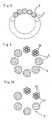
- Figs. 8, 9 and 10 are latitudinal cross sectional views of the wire-stranded helical hollow tube;
- Fig. 11 is a side elevati.onal view of a medical guide wire partly sectioned according to a second embodiment of the invention;
- Fig. 12 is a plan view of a medical guide wire partly shown according to a third embodiment of the invention;
- Fig. 13 is a perspective view of the medical guide wire partly shown;
- Fig. 14 is a longitudinal cross sectional view of a related art medical guide wire;
- Fig. 15 is a plan view of a needle tip of the related art puncture needle;
- Fig. 16 is a longitudinal cross sectional view of the related art medical guide wire partly shown; and
- Fig. 17 is an explanatory view of a preshaped tip in the related art medical guide wire.
-
- In the following description of the depicted embodiments, the same reference numerals are used for features of the same type.
- Referring to Figs. 1 through 10 which show a
medical guide wire 1 according to a first embodiment of the invention, the medical guide wire J. (abbreviated as "guide wire 1" hereinafter) is formed by a helical hollow wire body which is arranged to retractably move against aneedle Lip 6 of apuncture needle 5. The helical hollow wire body is formed into a wire-stranded helicalhollow tube 2 by stranding a multitude ofwire coil elements 3. Thewire coil elements 3 may be of stranded wires or a single one wire. - The
wire coil elements 3 of the wire-stranded helicalhollow tube 2 makes a stranding angle ( 1) of 55 degrees or less with an axial direction 4 of the wire-stranded helicalhollow tube 2. Thewire coil elements 3 further make an angle of more than plus 2 degrees upward or an angle of less than minus 2 degrees downward with a knife edge angle ( 2) of theneedle tip 6. - As for an intersectional direction between extension lines of the stranding angle ( 1)and the knife edge angle ( 2), the intersectional direction is in opposite directions between at a front elevational side and a rear elevational side of the
needle tip 6. It is sufficient to determine the stranding angle ( 1) and the angular differential requirement only at one of the front elevational side or the rear elevational side of theneedle tip 6. - As to the knife edge angle, there are shown two-step rake angles ( 2) and ( 3) which are provided with the
needle tip 6, and one or both of the knife edge angles is to have a close sliding relationship with theguide wire 1 as defined. - with the
guide wire 1 thus structured, the wire-stranded helicalhollow tube 2 is such that the bending force makes thewire coil elements 3 relatively slide, thus making thewire coil elements 3 engaged each other to prevent them from causing a clearance between thewire coil elements 3. This effectively prevents anedge portion 7 of thepuncture needle 5 from invading between thewire coil elements 3, thereby making it possible to smoothly insert theguide wire 1 into and pull from thepuncture needle 5. A certain number of thewire coil elements 3 are formed from the single one wire or the stranded wire, and stranded into a rope-shaped configuration to form them into the wire-stranded helicalhollow tube 2 which rarely gives a harmful clearance between thewire coil elements 3 even when manipulatively bent. - Based on the statistic data derived from the experimentations repeatedly carried out by using various types of specimens, the stranding angle is determined as for the
wire coil elements 3 of the wire-stranded helicalhollow tube 2. The stranding angle enables the manipulator to feel a reduced resistance accompanied when pulling the guide wire from the needle tip so as to insure a smooth and quick pulling operation for theguide wire 1. - As for the characteristics represented by pulling out the
guide wire 1 from thepuncture needle 6, Fig. 6 shows that the resistance against the pulling operation significantly reduces when the stranding angle ( 1) reaches 55 degrees and beyond. In this instance, the stranding angle ( 1) is between the helical lead angle formed and a central line 4 of the wire-stranded helicalhollow tube 2 as shown in Fig. 3. - As opposed to the related art depicted in Figs. 14 through 17, the characteristics based on the stranding angle ( 1) being less than 55 degrees tends to prevent the edge portion 7 (knife edge ends 7C, 7D) from inadvertently catching in the
wire coil elements 3 of the wire-stranded helicalhollow tube 2. - As to the angle of more than plus 2 degrees or an angle of less than minus 2 degrees with a knife edge angle ( 2) of the
needle tip 6, these angular determinations make the stranding angle ( 1) smaller than a winding angle which appears when the helical coil structure is formed by winding a single wire. When the stranding angle ( 1) becomes equal to the knife edge angle ( 2) of theneedle tip 6, the angle ( 1) would accidentally cause thewire coil elements 3 to lightly catch either one of the knife edge ends 7C, 7D of theneedle tip 6. - The angular differential requirement ( 1- 2) effectively prevents the knife edge ends 7C, 7D from invading into the the
wire coil elements 3. This is particularly advantageous when a distal end of theguide wire 1 is formed into a U-shaped or dog-legged configuration (P1) as shown in Fig. 11 as other embodiment of the invention. - Fig. 7 shows a relationship between the angular differential requirement ( 1- 2) and the pulling resistance R. It is found from Fig. 7 that the pulling resistance R significantly fall when the angular differential requirement ( 1- 2) is more than plus 2 degrees and less than minus 2 degrees. When the strandi.ng angle ( 1) becomes equal or near to the knife edge angle ( 2), the pulling resistance R is apparently found to increase rapidly.
- By determining the stranding angle ( 1) to be less than 55 degrees, the smaller stranding angle (0 1) makes the
wire coil elements 3 incline more. This prevents thewire coil elements 3 from being retained at both the knife edge ends 7C, 7D concurrently so as to engage thewire coil elements 3 with either one of the knife edge ends 7C, 7D. - By additionally setting the angular differential requirement ( 1- 2) to be more than plus 2 degrees, a relative angular difference is obtained between the knife edge angle ( 2) of the
needle tip 6 and aslantwise direction 8 defined when connecting the neighboringwire coil elements 3 upon engaging theguide wire 1 with theedge portion 7 when turning the guide wire upward at an entrance of the arteria carotia interna T. This reveals an intersectional configuration between an extension along the knife edge angle ( 0 2) and theslantwise direction 8 along a space appeared between the neighboringwire coil elements 3. - With the angular differential requirement ( 1- 2) set to be less than minus 2 degrees, it is possible to insure the intersectional configuration, the relative angular difference and the engaging condition of the
wire coil elements 3 brought against theedge portion 7 in the same manner mentioned above. This effectively prevents the knife edge ends 7C, 7D from invading between thewire coil elements 3 so as smoothly insert theguide wire 1 into and pull from thepuncture needle 5 with a good sliding performance. - With the angular differential requirement (( 1- 2) set to be more than plus 2 degrees, it is possible to increase the stranding angle ( 1) greater compared to the counterpart case in which the angular differential requirement ( 1- 2) is set to be less than minus 2 degrees. This is convenient especially upon forming the wire-stranded helical
hollow tube 2 diametrically larger and more flexibly. - With the angular differential requirement ( 1- 2) set to be less than minus 2 degrees, it is possible to decrease the stranding angle ( 1) smaller. This is convenient especially upon forming the wire-stranded helical
hollow tube 2 by the thinwire coil elements 3 with a high rigidity. - This makes it possible to readily insert the
guide wire 1 into thepuncture needle 5 with a good maneuverability, and making the diametrically reducedguide wire 1 less intrusive for the subject patient so as to mitigate the burden the subject patient suffers. - With the
guide wire 1 thus described, the stranding angle ( 1) and the angular differential requirement ( 1- 2) are such that the manipulatability is significantly improved upon inserting theguide wire 1 into and pulling it from the arteria carotis interna T through thepuncture needle 5. This renders the manipulative procedures efficient and smooth when operating thepuncture needle 5 to pierce into arteria carotis interna T in Lhe therapeutical method to insert the central venous catheter into the arteria carotis interna, thus significantly enhancing the curability so as to relieve the pains of the subject patient. - As shown in Table 1, dimensional designs are raised as product specimens A, B and C of the
guide wire 1 in which thewire coil elements 3 has the stranding angle ( 1), and theneedle tip 6 has the knife edge angle ( 2) as specified hereinbefore.
- Among the three specimens A, B and C, the latter two specimens B and C have the stranded wires at the
wire coil elements 3 so as to make theguide wire 1 more flexible based on the pliable property peculiar to the stranded wires. - With the wire-stranded helical
hollow tube 2 formed fromwire coil elements 3, as shown in Table 2, it is possible to reinforce the tensile rupture strength for the wire-stranded helicalhollow tube 2 so as to prevent theguide wire 1 from inadvertently breaking while manipulating it to give the subject patient the therapeutical procedures. It is convenient for the users when theguide wire 1 is produced with thepuncture needle 5 combined in pairs.
- Upon forming the wire-stranded helical
hollow tube 2 to produce the specimens A, B and C, thewire coil elements 3 are wound around a core member (not shown) with the use of a twisting machine (not shown) to provide a wound wire structure. Then, the core member is withdrawn after the wound wire structure is heat treated. Alternatively, thewire coil elements 3 are stranded along a predetermined circle line to form them into a helical coil structure. What instrument is used to provide the stranding angle ( 1) will be decided' depending on the stranded number and diametrical dimension of thewire coil elements 3 to produce. The stranding angle ( 1) can be adjusted in some degrees depending on the twisting force applied to thewi.re coil elements 3. - Fig. 11 shows a second embodiment of the invention in which a
head plug 14 is provided to give the guide wire 1 a smooth entry into the vascular vessel. Theguide wire 1 has amain wire portion 12 at the wire-stranded helicalhollow tube 2 into which anelongation core 13 is inserted. To both open ends of the main wire porti.on 12, thehead plug 14 is secured. - In this instance, the
main wire portion 12 may be formed by the specimen A in which a plurality of the wire coil elements are stranded. Otherwise, themain wire portion 12 may be provided by the specimen B and C in which both end portions of theelongation core 13 is tapered off toward its end portions so as to give them a high flexibility. - The
elongation core 13 is such that it shares bending stresses whenLhe guide wire 1 is subjected to a bending deformation. This protects thewire coil elements 3 against the accidental rupture which would otherwise be caused upon inserting the wire-stranded helicalhollow tube 2 into and pulling it from theneedle tip 6. Since thehead plug 14 is secured to both the ends of theelongation core 13, it makes theguide wire 1 insertable in any direction from its rear end and front end portion, while at the same time, rendering it selectively insertable among the rear end and front end portion depending on the diseased condition to be cured. This also makes theguide wire 1 durable enough to be reused several Limes. - Fig. 12 and 13 show a third embodiment of the invention in which a
stranding direction 15 ofline wires 3a of thewire coil elements 3 is the same or substantially the same to an axial direction 4 of the wire-stranded helicalhollow Lube 2. Namely, theline wires 3a are wound such that the strandingdirection 15 is substantially in paralell with the axial direction 4 of the wire-stranded helicalhollow tube 2. - This arrangement makes it possible to smoothly slide the wire-stranded helical
hollow tube 2 within thepuncture needle 5 so as to enable theguide wire 1 to a smooth insertion and pull-out operation against thepuncture needle 5. - Upon providing the wire-stranded helical
hollow tube 2, eighteenwire coil elements 3 are used to strand them in Lhe Z-direction so as to form a wire coil structure measured 0.81 mm in diameter. - The
line wires 3a (0.04 mm in diameter) are used to be twisted in the S-direction so as to form thewire coil elements 3 measured 0.12 mm in diameter (seven line wires stranded around one core line=1×7 structure). - While the
line wires 3a is substantially stranded in the axial direction 4 of the wire-stranded helicalhollow tube 2, it is possible to make theguide wire 1 slide smoothly against theedge portion 7 of theneedle tip 6 as long as an angular difference remains substantially within 6 degrees between the stranding direction 1.5 and the axial direction 4. The eighteenwire coil elements 3 are not necessarily stranded in the Z-direction and may be twisted in the S-direction, however, it is indispensable to strand theline wires 3a in the direction mutually opposite to the direction which thewire coil elements 3 are twisted. - In the related art guide wire in which the single one wire is helically wound to form the helical coil tube, when the helical tube slides at the
edge portion 7a of theneedle tip 6a, the helical tube easily stretches to reveal the clearance between the coil segments which are likely to hitch in theedge portion 7a so as to engage with theedge portion 7a. - On the contrary, according to the invention, the wire-stranded helical
hollow tube 2 is such that the wire-stranded helicalhollow tube 2 is unlikely to reveal the clearance between the coil segments. In addition, theline wires 3a is stranded substantially in the axial direction 4 of the wire-stranded helicalhollow tube 2, j.e., stranded in the lengthwise direction of thepuncture needle 5. This structure exerts the wire-stranded helicalhollow tube 2 to slide along thepuncture needle 5 when the wire-stranded helicalhollow tube 2 meets any of the knife edge ends 7A∼7D of theedge portion 7 of theneedle tip 6. This enables theguide wire 1 to a smooth insertion and easy pull-out operation against theneedle tip 6 so as to provide theguide wire 1 with a significantly smooth manipulatability. - It is to be noted that an outer surface of the wire-stranded helical
hollow tube 2 may be partly or entirely subjected to a diameter-reducing procedure by means of swaging or die mould work. An outer surface of thewire coil elements 3 may be similarly worked. With the diameter-reducing procedure thus provided, it is possible to impart a smooth surface and an improved rigidity to thewire coil elements 3 so as to insure a good slidability against thepuncture needle 5 and a good inserLion against the vascular vessel. - The wire-stranded helical
hollow tube 2 may be formed by twisting thewire coil elements 3 under the twist-resistant load, and thermally treated to remove the residual stress to insure a good rotation-following capability and straightness. Upon forming the wire-stranded helicalhollow tube 2, a part or an entire portion of the wire coil elements may be made of an austenitic stainless steel, shape-memory alloy or super-elastic alloy (e.g., Ni-Ti). Upon forming the wire-stranded helicalhollow tube 2, only a part of thewire coil elements 3 may be stranded.
Claims (8)
- A medical guide wire (1) formed by a helical hollow wire body which is arranged to retractably move through a needle tip (6) of a puncture needle (5);
said helical hollow wire body being formed as a wire-stranded helical hollow tube (2) by stranding a multitude of wire coil elements (3); and
said wire coil elements (3) of said wire-stranded helical hollow tube (2) making a stranding angle of 55 degrees or less with an axial direction of said wire-stranded helical hollow tube (2), and further making an angle of more than plus 2 degrees upward inclusive or an angle less than minus 2 degrees downward inclusive with a knife edge angle ( 2) of said needle tip (6). - The medical guide wire (1) according to claim 1, wherein wire coil elements (3) of said helical hollow wire body are formed from stranded wires (3a).
- A medical guide wire (1) formed by a helical hollow wire body which is arranged to retractably move through a needle tip (6) of a puncture needle (5);
said helical hollow wire body being formed as a wire-stranded helical hollow tube (2) by stranding a multitude of wire coil elements (3);
said wire coil elements (3) of said helical hollow wire body being formed from stranded wires (3a);
said wire coil elements (3) of said helical hollow wire body having a stranding direction mutually opposite to the stranding direction of said wire coil elements (3) of said wire-stranded helical hollow tube (2); and
said stranding wires (3a) of said wire coil elements (3) having a stranding direction substantially parallel with an axial direction (4) of said helical hollow wire body. - A medical guide wire according to claim 2, wherein:said wire coil elements (3) of said helical hollow wire body having a stranding direction mutually opposite to the stranding direction of said wire coil elements (3) of said wire-stranded helical hollow tube (2); andsaid stranding wires (3a) of said wire coil elements (3) having a stranding direction substantially parallel with an axial direction (4) of said helical hollow wire body of claim 3.
- The medical guide wire (1) according to claim 2, 3 or 4, wherein said stranded wires (3a) of said wire-stranded helical hollow tube (2) have an outer surface diametrically reduced by means of a reducing procedure.
- The medical guide wire (1) according to claim 2 and 3, wherein said puncture needle (5) is combined in pairs with guide wire (1).
- The medical guide wire (1) according to any preceding claim, wherein a head plug (14) is provided to both ends of a main wire line which forms said wire-stranded helical hollow tube (2).
- The medical guide (1) wire according to any preceding claim, wherein a U-shaped or dog-legged tip is preshaped as a preshaped tip (P1) at a distal end of said wire-stranded helical hollow tube (2).
Priority Applications (1)
| Application Number | Priority Date | Filing Date | Title |
|---|---|---|---|
| EP07001594A EP1772167B1 (en) | 2003-12-25 | 2004-12-23 | A medical guide wire |
Applications Claiming Priority (2)
| Application Number | Priority Date | Filing Date | Title |
|---|---|---|---|
| JP2003428575A JP2005185386A (en) | 2003-12-25 | 2003-12-25 | Medical guide wire |
| JP2003428575 | 2003-12-25 |
Related Child Applications (1)
| Application Number | Title | Priority Date | Filing Date |
|---|---|---|---|
| EP07001594A Division EP1772167B1 (en) | 2003-12-25 | 2004-12-23 | A medical guide wire |
Publications (3)
| Publication Number | Publication Date |
|---|---|
| EP1547638A2 true EP1547638A2 (en) | 2005-06-29 |
| EP1547638A3 EP1547638A3 (en) | 2005-11-09 |
| EP1547638B1 EP1547638B1 (en) | 2008-06-18 |
Family
ID=34544987
Family Applications (2)
| Application Number | Title | Priority Date | Filing Date |
|---|---|---|---|
| EP07001594A Not-in-force EP1772167B1 (en) | 2003-12-25 | 2004-12-23 | A medical guide wire |
| EP04258115A Not-in-force EP1547638B1 (en) | 2003-12-25 | 2004-12-23 | A medical guide wire |
Family Applications Before (1)
| Application Number | Title | Priority Date | Filing Date |
|---|---|---|---|
| EP07001594A Not-in-force EP1772167B1 (en) | 2003-12-25 | 2004-12-23 | A medical guide wire |
Country Status (6)
| Country | Link |
|---|---|
| US (1) | US7182757B2 (en) |
| EP (2) | EP1772167B1 (en) |
| JP (1) | JP2005185386A (en) |
| AT (2) | ATE409505T1 (en) |
| DE (2) | DE602004016893D1 (en) |
| HK (1) | HK1075420A1 (en) |
Cited By (4)
| Publication number | Priority date | Publication date | Assignee | Title |
|---|---|---|---|---|
| EP2505225A3 (en) * | 2011-03-30 | 2012-10-10 | Asahi Intecc Co., Ltd. | Guide wire |
| EP2865407A1 (en) * | 2013-10-25 | 2015-04-29 | Asahi Intecc Co., Ltd. | Coil body and guide wire |
| USD774646S1 (en) | 2015-04-30 | 2016-12-20 | Asahi Intecc Co., Ltd. | Coil body for medical use |
| CN110212393A (en) * | 2019-03-21 | 2019-09-06 | 安费诺电子装配(厦门)有限公司 | A kind of straight line beveling cable peeling device |
Families Citing this family (55)
| Publication number | Priority date | Publication date | Assignee | Title |
|---|---|---|---|---|
| US6379334B1 (en) * | 1997-02-10 | 2002-04-30 | Essex Technology, Inc. | Rotate advance catheterization system |
| WO2001023027A1 (en) | 1999-09-27 | 2001-04-05 | Essex Technology, Inc. | Rotate-to-advance catheterization system |
| US20090165784A1 (en) * | 2007-12-28 | 2009-07-02 | Tyco Healthcare Group Lp | Lubricious intubation device |
| US8545418B2 (en) | 2004-08-25 | 2013-10-01 | Richard R. Heuser | Systems and methods for ablation of occlusions within blood vessels |
| US20090012429A1 (en) * | 2004-08-25 | 2009-01-08 | Heuser Richard R | Catheter guidewire system using concentric wires |
| WO2006093976A1 (en) | 2005-02-28 | 2006-09-08 | Spirus Medical Inc. | Rotate-to-advance catheterization system |
| US8414477B2 (en) * | 2005-05-04 | 2013-04-09 | Olympus Endo Technology America Inc. | Rotate-to-advance catheterization system |
| US8317678B2 (en) | 2005-05-04 | 2012-11-27 | Olympus Endo Technology America Inc. | Rotate-to-advance catheterization system |
| US7780650B2 (en) | 2005-05-04 | 2010-08-24 | Spirus Medical, Inc. | Rotate-to-advance catheterization system |
| US8235942B2 (en) | 2005-05-04 | 2012-08-07 | Olympus Endo Technology America Inc. | Rotate-to-advance catheterization system |
| US8343040B2 (en) * | 2005-05-04 | 2013-01-01 | Olympus Endo Technology America Inc. | Rotate-to-advance catheterization system |
| US8574220B2 (en) | 2006-02-28 | 2013-11-05 | Olympus Endo Technology America Inc. | Rotate-to-advance catheterization system |
| US8435229B2 (en) | 2006-02-28 | 2013-05-07 | Olympus Endo Technology America Inc. | Rotate-to-advance catheterization system |
| WO2008144033A2 (en) * | 2007-05-18 | 2008-11-27 | Spirus Medical, Inc. | Rotate-to-advance catheterizaton system |
| US8870755B2 (en) | 2007-05-18 | 2014-10-28 | Olympus Endo Technology America Inc. | Rotate-to-advance catheterization system |
| JP5067845B2 (en) * | 2007-06-22 | 2012-11-07 | 朝日インテック株式会社 | Medical guidewire |
| US8048471B2 (en) * | 2007-12-21 | 2011-11-01 | Innovatech, Llc | Marked precoated medical device and method of manufacturing same |
| US8231927B2 (en) * | 2007-12-21 | 2012-07-31 | Innovatech, Llc | Marked precoated medical device and method of manufacturing same |
| US7811623B2 (en) * | 2007-12-21 | 2010-10-12 | Innovatech, Llc | Marked precoated medical device and method of manufacturing same |
| US7714217B2 (en) | 2007-12-21 | 2010-05-11 | Innovatech, Llc | Marked precoated strings and method of manufacturing same |
| US8231926B2 (en) | 2007-12-21 | 2012-07-31 | Innovatech, Llc | Marked precoated medical device and method of manufacturing same |
| US20100100055A1 (en) * | 2008-05-22 | 2010-04-22 | Td.Jam Medical Technologies , Llc | Devices for Superficial Femoral Artery Intervention |
| US8486022B2 (en) * | 2008-07-03 | 2013-07-16 | Abbott Cardiovascular Systems Inc. | Needle catheter with an angled distal tip lumen |
| WO2010083527A2 (en) | 2009-01-16 | 2010-07-22 | Claret Medical, Inc. | Intravascular blood filter |
| US20170202657A1 (en) | 2009-01-16 | 2017-07-20 | Claret Medical, Inc. | Intravascular blood filters and methods of use |
| US9326843B2 (en) | 2009-01-16 | 2016-05-03 | Claret Medical, Inc. | Intravascular blood filters and methods of use |
| US8568433B2 (en) | 2009-07-10 | 2013-10-29 | Cook Medical Technologies Llc | Medical device having one or more active strands |
| EP2459120A4 (en) | 2009-07-27 | 2017-11-01 | Claret Medical, Inc. | Dual endovascular filter and methods of use |
| US8100881B2 (en) | 2009-08-04 | 2012-01-24 | Cook Medical Technologies Llc | Flexible medical device for clot removal from small vessels |
| EP3300691B1 (en) | 2009-09-21 | 2021-06-30 | Boston Scientific Scimed, Inc. | Intravascular blood filters |
| JP5004256B2 (en) | 2009-12-25 | 2012-08-22 | 朝日インテック株式会社 | Medical guidewire |
| US9345565B2 (en) | 2010-12-30 | 2016-05-24 | Claret Medical, Inc. | Steerable dual filter cerebral protection system |
| US8900652B1 (en) | 2011-03-14 | 2014-12-02 | Innovatech, Llc | Marked fluoropolymer surfaces and method of manufacturing same |
| JP5360840B2 (en) * | 2011-03-31 | 2013-12-04 | 朝日インテック株式会社 | Guide wire |
| JP5424499B2 (en) * | 2011-04-18 | 2014-02-26 | 朝日インテック株式会社 | Medical guidewire |
| US8676301B2 (en) * | 2011-07-14 | 2014-03-18 | Med Works Limited | Guide wire incorporating a handle |
| JP2013094343A (en) * | 2011-10-31 | 2013-05-20 | Asahi Intecc Co Ltd | Guide wire |
| US10506934B2 (en) | 2012-05-25 | 2019-12-17 | Phyzhon Health Inc. | Optical fiber pressure sensor |
| WO2015051003A1 (en) | 2013-10-04 | 2015-04-09 | Vascular Imaging Corporation | Imaging techniques using an imaging guidewire |
| US10537255B2 (en) | 2013-11-21 | 2020-01-21 | Phyzhon Health Inc. | Optical fiber pressure sensor |
| JP6294211B2 (en) | 2014-02-24 | 2018-03-14 | 朝日インテック株式会社 | Guide wire |
| JP2015159865A (en) * | 2014-02-26 | 2015-09-07 | 朝日インテック株式会社 | guide wire |
| JP6482766B2 (en) * | 2014-03-19 | 2019-03-13 | 朝日インテック株式会社 | Guide wire |
| JP2015208362A (en) * | 2014-04-24 | 2015-11-24 | 朝日インテック株式会社 | Guide wire |
| JP2016013269A (en) * | 2014-07-02 | 2016-01-28 | 朝日インテック株式会社 | Guide wire |
| WO2016028486A1 (en) | 2014-08-21 | 2016-02-25 | Boston Scientific Scimed, Inc. | Medical device with support member |
| JP6153503B2 (en) * | 2014-09-26 | 2017-06-28 | 朝日インテック株式会社 | Guide wire |
| US10258240B1 (en) | 2014-11-24 | 2019-04-16 | Vascular Imaging Corporation | Optical fiber pressure sensor |
| US9566144B2 (en) | 2015-04-22 | 2017-02-14 | Claret Medical, Inc. | Vascular filters, deflectors, and methods |
| EP4052679A1 (en) | 2017-02-22 | 2022-09-07 | Boston Scientific Scimed, Inc. | Systems for protecting the cerebral vasculature |
| CN111565673A (en) | 2017-10-27 | 2020-08-21 | 波士顿科学医学有限公司 | System and method for protecting cerebral blood vessels |
| US11154390B2 (en) | 2017-12-19 | 2021-10-26 | Claret Medical, Inc. | Systems for protection of the cerebral vasculature during a cardiac procedure |
| WO2019210118A1 (en) | 2018-04-26 | 2019-10-31 | Boston Scientific Scimed, Inc. | Systems for protecting the cerebral vasculature |
| US11351023B2 (en) | 2018-08-21 | 2022-06-07 | Claret Medical, Inc. | Systems and methods for protecting the cerebral vasculature |
| CN216258739U (en) * | 2021-10-19 | 2022-04-12 | 苏州景昱医疗器械有限公司 | Implantable medical device and medical lead thereof |
Citations (9)
| Publication number | Priority date | Publication date | Assignee | Title |
|---|---|---|---|---|
| US4650472A (en) * | 1985-08-30 | 1987-03-17 | Cook, Incorporated | Apparatus and method for effecting percutaneous catheterization of a blood vessel using a small gauge introducer needle |
| US4951686A (en) * | 1985-02-26 | 1990-08-28 | B. Braun-Ssc Ag | Color marks on catheter guide wire |
| US5103543A (en) * | 1989-03-02 | 1992-04-14 | The Microspring Company, Inc. | Method of making a torque transmitter |
| US5373856A (en) * | 1992-09-29 | 1994-12-20 | Nivarox-Far S.A. | Catheter guide formed notably from a multistrand spring sheath |
| WO2000057944A1 (en) * | 1999-03-29 | 2000-10-05 | Cook Incorporated | A guidewire |
| US6165140A (en) * | 1998-12-28 | 2000-12-26 | Micrus Corporation | Composite guidewire |
| WO2002047755A2 (en) * | 2000-12-13 | 2002-06-20 | Advanced Cardiovascular System, Inc. | Dock exchange system for composite guide wires |
| EP1243283A2 (en) * | 2001-03-21 | 2002-09-25 | Asahi Intecc Co., Ltd. | A wire-stranded hollow tube, a medical tube body and a medical guide wire |
| WO2005016433A2 (en) * | 2003-07-31 | 2005-02-24 | Ev3 Inc. | Guide wire with stranded tip |
Family Cites Families (8)
| Publication number | Priority date | Publication date | Assignee | Title |
|---|---|---|---|---|
| US4850960A (en) * | 1987-07-08 | 1989-07-25 | Joseph Grayzel | Diagonally tapered, bevelled tip introducing catheter and sheath and method for insertion |
| US4932419A (en) * | 1988-03-21 | 1990-06-12 | Boston Scientific Corporation | Multi-filar, cross-wound coil for medical devices |
| US5527298A (en) * | 1990-06-11 | 1996-06-18 | Schneider (Usa) Inc. | Tracking guidewire |
| US5478328A (en) * | 1992-05-22 | 1995-12-26 | Silverman; David G. | Methods of minimizing disease transmission by used hypodermic needles, and hypodermic needles adapted for carrying out the method |
| US6171326B1 (en) * | 1998-08-27 | 2001-01-09 | Micrus Corporation | Three dimensional, low friction vasoocclusive coil, and method of manufacture |
| JPH10118192A (en) | 1996-10-16 | 1998-05-12 | Nippon Sherwood Medical Ind Ltd | Guide wire inserter |
| US6191365B1 (en) * | 1997-05-02 | 2001-02-20 | General Science And Technology Corp | Medical devices incorporating at least one element made from a plurality of twisted and drawn wires |
| EP1092449A1 (en) * | 1999-04-30 | 2001-04-18 | Usaminanotechnology, Inc. | Catheter and guide wire |
-
2003
- 2003-12-25 JP JP2003428575A patent/JP2005185386A/en active Pending
-
2004
- 2004-12-22 US US11/018,394 patent/US7182757B2/en active Active
- 2004-12-23 AT AT07001594T patent/ATE409505T1/en not_active IP Right Cessation
- 2004-12-23 EP EP07001594A patent/EP1772167B1/en not_active Not-in-force
- 2004-12-23 DE DE602004016893T patent/DE602004016893D1/en active Active
- 2004-12-23 EP EP04258115A patent/EP1547638B1/en not_active Not-in-force
- 2004-12-23 AT AT04258115T patent/ATE398475T1/en not_active IP Right Cessation
- 2004-12-23 DE DE602004014464T patent/DE602004014464D1/en active Active
-
2005
- 2005-10-18 HK HK05109161A patent/HK1075420A1/en not_active IP Right Cessation
Patent Citations (9)
| Publication number | Priority date | Publication date | Assignee | Title |
|---|---|---|---|---|
| US4951686A (en) * | 1985-02-26 | 1990-08-28 | B. Braun-Ssc Ag | Color marks on catheter guide wire |
| US4650472A (en) * | 1985-08-30 | 1987-03-17 | Cook, Incorporated | Apparatus and method for effecting percutaneous catheterization of a blood vessel using a small gauge introducer needle |
| US5103543A (en) * | 1989-03-02 | 1992-04-14 | The Microspring Company, Inc. | Method of making a torque transmitter |
| US5373856A (en) * | 1992-09-29 | 1994-12-20 | Nivarox-Far S.A. | Catheter guide formed notably from a multistrand spring sheath |
| US6165140A (en) * | 1998-12-28 | 2000-12-26 | Micrus Corporation | Composite guidewire |
| WO2000057944A1 (en) * | 1999-03-29 | 2000-10-05 | Cook Incorporated | A guidewire |
| WO2002047755A2 (en) * | 2000-12-13 | 2002-06-20 | Advanced Cardiovascular System, Inc. | Dock exchange system for composite guide wires |
| EP1243283A2 (en) * | 2001-03-21 | 2002-09-25 | Asahi Intecc Co., Ltd. | A wire-stranded hollow tube, a medical tube body and a medical guide wire |
| WO2005016433A2 (en) * | 2003-07-31 | 2005-02-24 | Ev3 Inc. | Guide wire with stranded tip |
Cited By (5)
| Publication number | Priority date | Publication date | Assignee | Title |
|---|---|---|---|---|
| EP2505225A3 (en) * | 2011-03-30 | 2012-10-10 | Asahi Intecc Co., Ltd. | Guide wire |
| EP2865407A1 (en) * | 2013-10-25 | 2015-04-29 | Asahi Intecc Co., Ltd. | Coil body and guide wire |
| USD774646S1 (en) | 2015-04-30 | 2016-12-20 | Asahi Intecc Co., Ltd. | Coil body for medical use |
| CN110212393A (en) * | 2019-03-21 | 2019-09-06 | 安费诺电子装配(厦门)有限公司 | A kind of straight line beveling cable peeling device |
| CN110212393B (en) * | 2019-03-21 | 2024-02-20 | 安费诺电子装配(厦门)有限公司 | Linear oblique tangent cable peeling device |
Also Published As
| Publication number | Publication date |
|---|---|
| HK1075420A1 (en) | 2005-12-16 |
| US20050154371A1 (en) | 2005-07-14 |
| DE602004014464D1 (en) | 2008-07-31 |
| US7182757B2 (en) | 2007-02-27 |
| EP1772167A2 (en) | 2007-04-11 |
| ATE409505T1 (en) | 2008-10-15 |
| ATE398475T1 (en) | 2008-07-15 |
| DE602004016893D1 (en) | 2008-11-13 |
| JP2005185386A (en) | 2005-07-14 |
| EP1772167A3 (en) | 2007-06-06 |
| EP1772167B1 (en) | 2008-10-01 |
| EP1547638B1 (en) | 2008-06-18 |
| EP1547638A3 (en) | 2005-11-09 |
Similar Documents
| Publication | Publication Date | Title |
|---|---|---|
| EP1547638B1 (en) | A medical guide wire | |
| JP4993632B2 (en) | Medical guidewire | |
| US8608670B2 (en) | Guidewire | |
| EP2338555B1 (en) | Guidewire | |
| EP2962718B1 (en) | Guidewire | |
| EP2263735B1 (en) | Medical Guidewire | |
| EP2263737A1 (en) | Medical guidewire | |
| JP5226906B1 (en) | MEDICAL COIL, MANUFACTURING METHOD THEREOF, AND MEDICAL DEVICE | |
| US9492642B2 (en) | Guidewire | |
| JP4609903B2 (en) | Medical guidewire | |
| EP2921195A1 (en) | Guide wire | |
| JP5459723B2 (en) | Medical guidewire | |
| JP5780532B2 (en) | Medical guidewire | |
| JP5376542B2 (en) | Medical guidewire |
Legal Events
| Date | Code | Title | Description |
|---|---|---|---|
| PUAI | Public reference made under article 153(3) epc to a published international application that has entered the european phase |
Free format text: ORIGINAL CODE: 0009012 |
|
| AK | Designated contracting states |
Kind code of ref document: A2 Designated state(s): AT BE BG CH CY CZ DE DK EE ES FI FR GB GR HU IE IS IT LI LT LU MC NL PL PT RO SE SI SK TR |
|
| AX | Request for extension of the european patent |
Extension state: AL BA HR LV MK YU |
|
| PUAL | Search report despatched |
Free format text: ORIGINAL CODE: 0009013 |
|
| AK | Designated contracting states |
Kind code of ref document: A3 Designated state(s): AT BE BG CH CY CZ DE DK EE ES FI FR GB GR HU IE IS IT LI LT LU MC NL PL PT RO SE SI SK TR |
|
| AX | Request for extension of the european patent |
Extension state: AL BA HR LV MK YU |
|
| RIC1 | Information provided on ipc code assigned before grant |
Ipc: 7A 61M 25/09 B Ipc: 7A 61M 25/01 A |
|
| REG | Reference to a national code |
Ref country code: HK Ref legal event code: DE Ref document number: 1075420 Country of ref document: HK |
|
| 17P | Request for examination filed |
Effective date: 20060123 |
|
| AKX | Designation fees paid |
Designated state(s): AT BE BG CH CY CZ DE DK EE ES FI FR GB GR HU IE IS IT LI LT LU MC NL PL PT RO SE SI SK TR |
|
| 17Q | First examination report despatched |
Effective date: 20060518 |
|
| 17Q | First examination report despatched |
Effective date: 20060518 |
|
| GRAP | Despatch of communication of intention to grant a patent |
Free format text: ORIGINAL CODE: EPIDOSNIGR1 |
|
| GRAS | Grant fee paid |
Free format text: ORIGINAL CODE: EPIDOSNIGR3 |
|
| GRAA | (expected) grant |
Free format text: ORIGINAL CODE: 0009210 |
|
| AK | Designated contracting states |
Kind code of ref document: B1 Designated state(s): AT BE BG CH CY CZ DE DK EE ES FI FR GB GR HU IE IS IT LI LT LU MC NL PL PT RO SE SI SK TR |
|
| REG | Reference to a national code |
Ref country code: GB Ref legal event code: FG4D |
|
| REF | Corresponds to: |
Ref document number: 602004014464 Country of ref document: DE Date of ref document: 20080731 Kind code of ref document: P |
|
| REG | Reference to a national code |
Ref country code: CH Ref legal event code: EP |
|
| REG | Reference to a national code |
Ref country code: IE Ref legal event code: FG4D |
|
| REG | Reference to a national code |
Ref country code: HK Ref legal event code: GR Ref document number: 1075420 Country of ref document: HK |
|
| PG25 | Lapsed in a contracting state [announced via postgrant information from national office to epo] |
Ref country code: SI Free format text: LAPSE BECAUSE OF FAILURE TO SUBMIT A TRANSLATION OF THE DESCRIPTION OR TO PAY THE FEE WITHIN THE PRESCRIBED TIME-LIMIT Effective date: 20080618 Ref country code: FI Free format text: LAPSE BECAUSE OF FAILURE TO SUBMIT A TRANSLATION OF THE DESCRIPTION OR TO PAY THE FEE WITHIN THE PRESCRIBED TIME-LIMIT Effective date: 20080618 |
|
| PG25 | Lapsed in a contracting state [announced via postgrant information from national office to epo] |
Ref country code: AT Free format text: LAPSE BECAUSE OF FAILURE TO SUBMIT A TRANSLATION OF THE DESCRIPTION OR TO PAY THE FEE WITHIN THE PRESCRIBED TIME-LIMIT Effective date: 20080618 Ref country code: NL Free format text: LAPSE BECAUSE OF FAILURE TO SUBMIT A TRANSLATION OF THE DESCRIPTION OR TO PAY THE FEE WITHIN THE PRESCRIBED TIME-LIMIT Effective date: 20080618 Ref country code: PL Free format text: LAPSE BECAUSE OF FAILURE TO SUBMIT A TRANSLATION OF THE DESCRIPTION OR TO PAY THE FEE WITHIN THE PRESCRIBED TIME-LIMIT Effective date: 20080618 |
|
| NLV1 | Nl: lapsed or annulled due to failure to fulfill the requirements of art. 29p and 29m of the patents act | ||
| PG25 | Lapsed in a contracting state [announced via postgrant information from national office to epo] |
Ref country code: SE Free format text: LAPSE BECAUSE OF FAILURE TO SUBMIT A TRANSLATION OF THE DESCRIPTION OR TO PAY THE FEE WITHIN THE PRESCRIBED TIME-LIMIT Effective date: 20080918 Ref country code: CZ Free format text: LAPSE BECAUSE OF FAILURE TO SUBMIT A TRANSLATION OF THE DESCRIPTION OR TO PAY THE FEE WITHIN THE PRESCRIBED TIME-LIMIT Effective date: 20080618 Ref country code: ES Free format text: LAPSE BECAUSE OF FAILURE TO SUBMIT A TRANSLATION OF THE DESCRIPTION OR TO PAY THE FEE WITHIN THE PRESCRIBED TIME-LIMIT Effective date: 20080929 Ref country code: PT Free format text: LAPSE BECAUSE OF FAILURE TO SUBMIT A TRANSLATION OF THE DESCRIPTION OR TO PAY THE FEE WITHIN THE PRESCRIBED TIME-LIMIT Effective date: 20081118 Ref country code: IS Free format text: LAPSE BECAUSE OF FAILURE TO SUBMIT A TRANSLATION OF THE DESCRIPTION OR TO PAY THE FEE WITHIN THE PRESCRIBED TIME-LIMIT Effective date: 20081018 Ref country code: LT Free format text: LAPSE BECAUSE OF FAILURE TO SUBMIT A TRANSLATION OF THE DESCRIPTION OR TO PAY THE FEE WITHIN THE PRESCRIBED TIME-LIMIT Effective date: 20080618 |
|
| PG25 | Lapsed in a contracting state [announced via postgrant information from national office to epo] |
Ref country code: SK Free format text: LAPSE BECAUSE OF FAILURE TO SUBMIT A TRANSLATION OF THE DESCRIPTION OR TO PAY THE FEE WITHIN THE PRESCRIBED TIME-LIMIT Effective date: 20080618 Ref country code: RO Free format text: LAPSE BECAUSE OF FAILURE TO SUBMIT A TRANSLATION OF THE DESCRIPTION OR TO PAY THE FEE WITHIN THE PRESCRIBED TIME-LIMIT Effective date: 20080618 Ref country code: BE Free format text: LAPSE BECAUSE OF FAILURE TO SUBMIT A TRANSLATION OF THE DESCRIPTION OR TO PAY THE FEE WITHIN THE PRESCRIBED TIME-LIMIT Effective date: 20080618 |
|
| PGFP | Annual fee paid to national office [announced via postgrant information from national office to epo] |
Ref country code: IT Payment date: 20081222 Year of fee payment: 5 |
|
| PLBE | No opposition filed within time limit |
Free format text: ORIGINAL CODE: 0009261 |
|
| STAA | Information on the status of an ep patent application or granted ep patent |
Free format text: STATUS: NO OPPOSITION FILED WITHIN TIME LIMIT |
|
| PG25 | Lapsed in a contracting state [announced via postgrant information from national office to epo] |
Ref country code: EE Free format text: LAPSE BECAUSE OF FAILURE TO SUBMIT A TRANSLATION OF THE DESCRIPTION OR TO PAY THE FEE WITHIN THE PRESCRIBED TIME-LIMIT Effective date: 20080618 Ref country code: DK Free format text: LAPSE BECAUSE OF FAILURE TO SUBMIT A TRANSLATION OF THE DESCRIPTION OR TO PAY THE FEE WITHIN THE PRESCRIBED TIME-LIMIT Effective date: 20080618 Ref country code: BG Free format text: LAPSE BECAUSE OF FAILURE TO SUBMIT A TRANSLATION OF THE DESCRIPTION OR TO PAY THE FEE WITHIN THE PRESCRIBED TIME-LIMIT Effective date: 20080918 |
|
| PGFP | Annual fee paid to national office [announced via postgrant information from national office to epo] |
Ref country code: FR Payment date: 20081212 Year of fee payment: 5 |
|
| 26N | No opposition filed |
Effective date: 20090319 |
|
| PG25 | Lapsed in a contracting state [announced via postgrant information from national office to epo] |
Ref country code: MC Free format text: LAPSE BECAUSE OF NON-PAYMENT OF DUE FEES Effective date: 20081231 |
|
| REG | Reference to a national code |
Ref country code: CH Ref legal event code: PL |
|
| PG25 | Lapsed in a contracting state [announced via postgrant information from national office to epo] |
Ref country code: IE Free format text: LAPSE BECAUSE OF NON-PAYMENT OF DUE FEES Effective date: 20081223 Ref country code: CH Free format text: LAPSE BECAUSE OF NON-PAYMENT OF DUE FEES Effective date: 20081231 Ref country code: LI Free format text: LAPSE BECAUSE OF NON-PAYMENT OF DUE FEES Effective date: 20081231 |
|
| PG25 | Lapsed in a contracting state [announced via postgrant information from national office to epo] |
Ref country code: LU Free format text: LAPSE BECAUSE OF NON-PAYMENT OF DUE FEES Effective date: 20081223 Ref country code: CY Free format text: LAPSE BECAUSE OF FAILURE TO SUBMIT A TRANSLATION OF THE DESCRIPTION OR TO PAY THE FEE WITHIN THE PRESCRIBED TIME-LIMIT Effective date: 20080618 Ref country code: HU Free format text: LAPSE BECAUSE OF FAILURE TO SUBMIT A TRANSLATION OF THE DESCRIPTION OR TO PAY THE FEE WITHIN THE PRESCRIBED TIME-LIMIT Effective date: 20081219 |
|
| PG25 | Lapsed in a contracting state [announced via postgrant information from national office to epo] |
Ref country code: TR Free format text: LAPSE BECAUSE OF FAILURE TO SUBMIT A TRANSLATION OF THE DESCRIPTION OR TO PAY THE FEE WITHIN THE PRESCRIBED TIME-LIMIT Effective date: 20080618 |
|
| REG | Reference to a national code |
Ref country code: FR Ref legal event code: ST Effective date: 20100831 |
|
| PG25 | Lapsed in a contracting state [announced via postgrant information from national office to epo] |
Ref country code: GR Free format text: LAPSE BECAUSE OF FAILURE TO SUBMIT A TRANSLATION OF THE DESCRIPTION OR TO PAY THE FEE WITHIN THE PRESCRIBED TIME-LIMIT Effective date: 20080919 Ref country code: FR Free format text: LAPSE BECAUSE OF NON-PAYMENT OF DUE FEES Effective date: 20091231 |
|
| PG25 | Lapsed in a contracting state [announced via postgrant information from national office to epo] |
Ref country code: IT Free format text: LAPSE BECAUSE OF NON-PAYMENT OF DUE FEES Effective date: 20091223 |
|
| PGFP | Annual fee paid to national office [announced via postgrant information from national office to epo] |
Ref country code: GB Payment date: 20121220 Year of fee payment: 9 |
|
| PGFP | Annual fee paid to national office [announced via postgrant information from national office to epo] |
Ref country code: DE Payment date: 20121220 Year of fee payment: 9 |
|
| REG | Reference to a national code |
Ref country code: DE Ref legal event code: R119 Ref document number: 602004014464 Country of ref document: DE |
|
| GBPC | Gb: european patent ceased through non-payment of renewal fee |
Effective date: 20131223 |
|
| REG | Reference to a national code |
Ref country code: DE Ref legal event code: R119 Ref document number: 602004014464 Country of ref document: DE Effective date: 20140701 |
|
| PG25 | Lapsed in a contracting state [announced via postgrant information from national office to epo] |
Ref country code: DE Free format text: LAPSE BECAUSE OF NON-PAYMENT OF DUE FEES Effective date: 20140701 |
|
| PG25 | Lapsed in a contracting state [announced via postgrant information from national office to epo] |
Ref country code: GB Free format text: LAPSE BECAUSE OF NON-PAYMENT OF DUE FEES Effective date: 20131223 |