BACKGROUND OF THE INVENTION
1. Field of the Invention
-
The present invention relates to a product identification data
management system and method for managing identification data attached to
products.
2. Description of the Related Art
-
Bar codes are affixed on most products dealt with in stores. A bar code is
a combination of varying-width parallel bars and spaces and represents
numerical data or symbolic data. The bar code is read using a bar code reader
as a dedicated input device, so that data of the corresponding product can be
obtained. Therefore, data concerned with each product can be rapidly input
with accuracy without using an input device such as a keyboard to manually
input data. Accordingly, bar codes are attached to many products and are
effectively used.
-
Typical data represented using a bar code affixed on a product includes,
for example, JAN (Japanese Article Number) code. The JAN code consists of
13 or 8 digits. The JAN code includes a country code indicating in what country
the corresponding product was produced, a manufacturer code indicating the
manufacturer of the product, a product code specifying the product, and a check
digit. Advantageously, the quantity of stock and the sale proceeds can be
immediately grasped using barcodes affixed on respective products.
-
When a bar code consists of, e.g., 13 digits, data indicating the product
code corresponds to only 5 digits. Unfortunately, detailed information such as
the name of the product and its price cannot be obtained from the read JAN
code. In the application of bar codes for product management, an approach of
using a bar code as ID, i,e., identification data for database retrieval is used.
The bar code can include only identification data to specify the corresponding
product, so that the number of digits can be reduced. As identification data
included in a bar code, for example, a product code, an order number, a
delivery number, a drawing number, a manufacturing management number, an
operating instruction number, or a serial number is used.
-
A user uses a bar code reader to scan a bar code attached on a product,
thus reading data of the bar code. Accordingly, bar codes are not suitable for
checking the quantity of stock of an item after products of the item are arranged
in a showcase. Hence, an approach of adding a radio frequency (RF) tag to
each product is proposed.
-
The RF tag is also called an electronic tag (integrated circuit tag; IC tag).
Data concerned with a product is read using radio waves generated from the
corresponding tag. It is unnecessary to move a tag reader close to a product in
order to scan a tag affixed on the product. Advantageously, RF tags are
attached to various products such as clothing, food, daily needs, and books.
The RF tag can have various capabilities for stock management, sales
management, ensuring traceability, theft prevention, and information service. In
addition, the RF tag has extremely higher information processing capability than
those of already-existing bar code systems. Data can be rewritten or added to
the RF tag.
-
The above-mentioned RF tag is being minimized as a combination of an
IC chip and an antenna and its price is being plunged. There are signs of
widespread proliferation of RF tags. Japanese Unexamined Patent Application
Publication No. 2001-287810 (Reference 1) discloses a technique of affixing an
RF tag, called an electronic product code (EPC) to identify each individual
product, on each product for product distribution management.
-
The bar code systems have already been widespread as mentioned
above. The application field thereof is not limited to recording codes of various
products with registers serving as point-of sale (POS) terminals at the point of
sale to count sold products. For example, data corresponding to respective bar
codes are registered in a database so that the bar codes are used for
accounting treatment of sold products. Various processes are established in
product management using bar codes.
-
To achieve greater proliferation of RF tags, it is necessary that RF tag
systems coexist with the already-existing established bar code systems for the
bar code system users' convenience and making the smooth transition to the
new systems. For this purpose, for example, both of a bar code and an RF tag
are temporarily attached to each product.
-
Each RF tag has larger data capacity than that of each bar code.
Accordingly, RF tag data represented by the RF tag can include bar code data
represented by the bar code. When the magnitude relationship between two
kinds of data capacities is found, identification data of one identification data
system (large-capacity data system) with a large data capacity contains
identification data of the other identification data system (small-capacity data
system) with a small data capacity, so that the two kinds of identification data
can be related with each other.
-
In the above-mentioned relating, identification data of the small-capacity
data system is written in identification data of the large-capacity data system.
Regarding the attachment of a tag including identification data of the large-capacity
data system to each product, disadvantageously, the tag cannot be
attached to the product unless a bar code including identification data of the
small-capacity data system has already been attached to the product. In
addition, if new identification data of the small-capacity data system is used, it is
necessary to form tags including identification data of the large-capacity data
system so that the identification data of the large-capacity data system includes
the new identification data of the small-capacity data system. In other words, it
is necessary to always recognize identification data of the small-capacity data
system when the corresponding tag is fabricated. Disadvantageously, the
fabrication of tags and the management of identification data are difficult.
-
To overcome the above disadvantages, a technique of mixing a keyword
of one data system, indicating the features of an individual, as an exchangeable
keyword into identification data of the other data system is proposed. For
example, Japanese Unexamined Patent Application Publication No. 2000-276477
(Reference 2) discloses such a technique.
-
According to the above technique, since a keyword of one data system
indicating the features of an individual is mixed as an exchangeable keyword
into identification data of the other data system, keywords can be flexibly set to
some extent. However, it is necessary to find a keyword by keyword matching.
According to this technique, therefore, it is necessary to generate identification
data of one data system in consideration of the other data system.
Disadvantageously, the dependence between two data systems cannot be
eliminated.
SUMMARY OF THE INVENTION
-
Accordingly, it is an object of the present invention to provide a product
identification data management system and method capable of adding
identification data of different data systems to each product independently of
each other and also capable of relating the identification data of the two data
systems with each other.
-
According to a first aspect of the present invention, a product
identification data management system includes: (a) an identification data input
unit for inputting identification data of two data systems added to each product
such that the identification data of one data system is related with that of the
other data system every product; (b) a database for storing the identification
data of the two data systems input by the identification data input unit such that
the identification data of one data system is related with that of the other data
system every product; and (c) a database retrieval unit for retrieving the
identification data of one data system from the database and acquiring the
identification data when the identification data of the other data system is
designated.
-
In other words, according to the first aspect of the present invention, the
identification data input unit inputs identification data of two data systems
actually added to a product or to be added thereto. The identification data of
the two data systems are stored in the database such that they are related with
each other every product. Thus, when any of the identification data of the two
data systems is designated, the identification data of the designated data
system is retrieved from the database, so that the identification data of the other
data system can be acquired. In addition, the identification data of the two data
systems can be related with each other in the database. Thus, each
identification data can be independently operated.
-
According to a second aspect of the present invention, a product
identification data management system includes: (a) a relation mode reading
unit for reading identification data of two data systems correctly added to each
product in order to identify the same product; (b) a relating unit for relating the
class fields of the identification data of the two data systems, read by the
relation mode reading unit, with each other every kind of product, the class field
serving as a data segment to identify the kind of product; (c) a database for
storing the identification data of the two data systems with the class fields
related by the relating unit; and (d) a database retrieval unit for retrieving the
identification data of one data system from the database and acquiring the
identification data when the class field of the identification data of the other data
system is designated.
-
In other words, according to the second aspect of the present invention,
the relation mode reading unit reads identification data of two data systems
correctly added to each product in order to identify the same product. The
identification data of the two data systems can be read simultaneously,
successively, or at different times. The relating unit relates the class fields of
the identification data of the two data systems with each other every kind of
product. The class field serves as a data segment to identify the kind of product.
The related identification data of the two data systems are stored in the
database. Thus, when the class field of the identification data of any of the two
data systems is designated, the identification data of the other data system can
be acquired with reference to the database. In addition, the identification data
of the two data systems are related with each other in the database. Thus,
each identification data can be independently operated.
-
According to a third aspect of the present invention, a product
identification data management system includes: (a) a relation mode reading
unit for reading identification data of two data systems correctly added to each
product in order to identify the same product; (b) a relating unit for relating the
class fields of the identification data of the two data systems, read by the
relation mode reading unit, with each other every kind of product, the class field
serving as a data segment to identify the kind of product; (c) a database for
storing the identification data of the two data systems with the class fields
related by the relating unit; (d) a check mode reading unit for reading
identification data of the two data systems added to the same product in order
to check the unknown relation therebetween; (e) a check mode retrieval unit for
retrieving identification data of one data system, which is related with the
identification data of the other data system read by the check mode reading unit,
from the database; (f) an identification data checking unit for checking whether
the identification data retrieved by the check mode retrieval unit is identical to
the identification data with the related class field read by the check mode
reading unit; and (g) a relation determination unit for determining that the
identification data of the two data systems with the unknown relation
therebetween added to the product, read by the check mode reading unit, are
related with each other as identification data of the same product when the
identification data checking unit obtains the consistency of both the identification
data, and for determining that the identification data of the two data systems are
not related with each other as identification data of the same product in other
cases.
-
In other words, according to the third aspect of the present invention,
when identification data of the two data systems are added to each product on
condition that the database for storing the related identification data of the two
data systems is constructed in a manner similar to the invention disclosed in
Claim 2, the consistency therebetween for the same product is checked. To
check the consistency therebetween, on the basis of identification data of one
data system read from the product to be checked, identification data of the other
data system is acquired from the database. Whether the acquired identification
data is identical to the identification data read from the product is determined.
Thus, after identification data of the two data systems are added to each
product, the consistency therebetween can be easily checked.
-
According to the fourth aspect of the invention, a product identification
data management system includes: a first computer-readable recording medium
for recording first identification data, the first recording medium being attached
to each product to be managed; a second computer-readable recording medium
for recording second identification data having a data system independent of
that of the first identification data, the second recording medium being attached
to each product together with the first recording medium; a first storage device
for storing the first identification data and data recorded in connection with the
first identification data; a second storage device for storing the first and second
identification data such that the first identification data recorded in the first
recording medium attached to the product is related with the second
identification data recorded in the second recording medium attached to the
same product; and a processor for executing a process of retrieving data on the
basis of input second identification data by using first identification data
corresponding to the input second identification data.
-
In the fourth aspect, during the transition to a new code system or a new
recording medium used to add identification data to a product, e.g., the
transition from a bar code to an RF tag, the new code system can be added to
the product independently of an old code system. In addition, the new code
system can utilize a database constructed in association with the old code
system. In this case, the system may further include a third storage device for
storing the second identification data and data recorded in connection with the
second identification data.
-
In the fourth aspect, the system may further include a processor for
executing a process of checking data stored in the first storage device against
data stored in the third storage device on the basis of the relation stored in the
second storage device. The first to third storage devices may be the same
storage device.
-
In the system of the fourth aspect, the first recording medium may include
a bar code printed matter and the second recording medium may include an RF
tag.
-
As mentioned above, according to the present invention, identification
data of two data systems are externally related with each other, the relation
therebetween is stored in a database. Accordingly, identification data of one
data system need not include all or a part of identification data of the other data
system. Since identification data of the two data systems need not depend on
each other, the identification data of the two data systems can be independently
managed. In addition, identification data itself need not include excess
information, thus resulting in efficient data structure.
BRIEF DESCRIPTION OF THE DRAWINGS
-
- Fig. 1 is a schematic diagram of the structure of a product identification
data management system according to a first embodiment of the present
invention;
- Fig. 2 is a perspective view of an input device, which is reading
identification data concerned with a product, arranged in a purchasing
department according to the first embodiment;
- Fig. 3 is a block diagram of the principle structure of the product
identification data management system according to the first embodiment;
- Fig. 4 is a table explaining the content of a first database at
predetermined time according to the first embodiment;
- Fig. 5 is a table explaining the content of a second database according to
the first embodiment;
- Fig. 6 is a flowchart of a process of a relating unit according to the first
embodiment;
- Fig. 7 is a flowchart of a process of a data updating unit in response to a
request in step S202;
- Fig. 8 is a table explaining the content of the first database after a
processing step in S221 is performed;
- Fig. 9 is a flowchart of a process of a product data terminal when a
terminal user issues a request to acquire data concerned with a product in the
first embodiment;
- Fig. 10 is a flowchart of a process of an in-store processor when the
terminal user issues a request to acquire data concerned with the product in the
first embodiment;
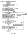
- Fig. 11 is a flowchart specifically showing a process of a first data
providing unit according to the first embodiment;
- Fig. 12 is a flowchart specifically showing a process of a second data
providing unit according to the first embodiment;
- Fig. 13 is a block diagram of the principle structure of an essential part of
a product identification data management system according to a second
embodiment of the present invention;
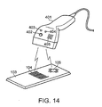
- Fig. 14 is a perspective view of an input-output device, which is reading
identification data of a product, according to the second embodiment;
- Fig. 15 is a flowchart mainly showing a process in a consistency check
mode according to the second embodiment;
- Fig. 16 is a block diagram of the principle structure of an essential part of
a product identification data management system according to a third
embodiment of the present invention;
- Fig. 17 is a table explaining the content of a first database at certain time
according to the third embodiment;
- Fig. 18 is a table explaining the content of the first database at time
subsequent to the certain time in Fig. 17;
- Fig. 19 is a block diagram of the principle structure of an essential part of
a product identification data management system according to a fourth
embodiment of the present invention;
- Fig. 20 is a table partially showing data stored in a second database
according to the fourth embodiment; and
- Fig. 21 is a table explaining the content of the second database at time
subsequent to time at which the database has data in Fig. 20.
-
DESCRIPTION OF THE PREFERRED EMBODIMENTS
-
Embodiments of the present invention will now be described in detail
below.
First Embodiment
-
Fig. 1 shows an overview of a product identification data management
system 100 according to a first embodiment of the present invention. The
product identification data management system 100 manages products handled
in stores of a specific sales company using a communication network 101 such
as the Internet or an Intranet. In a factory 102, each of the products 103 is
affixed with a bar code 104 indicating a manufacturer code and a product code
and an RF tag 105 with identifier whereby the corresponding product can be
uniquely identified. Then the products 103 are shipped out. The products 103
are stored in a warehouse 106 and appropriately delivered to a purchasing
department 107 of the sales company. The purchasing department 107, an
information department 108, and the store of the company 109 are connected to
the communication network 101. Although one factory 102, one warehouse 106,
one purchasing department 107, and one store 109 are shown in Fig. 1, the
arrangement is not limited to this case. For example, if the products are
purchased on a nationwide scale, the purchasing department 107 can be
dispersed. Each purchasing department 107 can purchase the products
fabricated in the corresponding area. The stores 109 can be dispersed in
various regions. Each information department 108 can be directly connected to
the corresponding purchasing department 107. Alternatively, a plurality of
information departments 108 can be connected to the communication network
101 for data backup.
-
The purchasing department 107 includes an input data terminal 111 and
an input device 112. The input data terminal 111 connects to the
communication network 101 and performs various data processings. The input
device 112 reads data of the bar code 104 and data of the RF tag 105 attached
to each product and inputs the data to the input data terminal 111. The input
data terminal 111 is a data processing unit including a personal computer or a
workstation. The input data terminal 111 has a central processing unit (CPU)
(not shown) and a storage medium in which a predetermined control program is
stored. The input data terminal 111 relates the data of the bar code 104 to that
of the RF tag 105 as described later.
-
The information department 108 has a data management device 114
including a personal computer, and first and second databases 115 and 116
connected to the device 114. The data management device 114 having a
communication function is connected to the communication network 101. The
first database 115 relates to the bar code 104. The second database 116
relates to the RF tag 105.
-
The store 109 includes a personal computer and has an in-store
processor 117 for controlling data processing in the store. The in-store
processor 117 connects to a plurality of product data terminals 118 provided for,
e.g., respective cash registers via communication means such as local area
network (LAN) cables. Each product data terminal 118 also includes a personal
computer or a simplified data processor. The throughput of the product data
terminal 118 can be lower than that of the in-store processor 117. Each product
data terminal 118 connects to either or both of a bar code reader 119 and an RF
tag reader 120.
-
Fig. 2 shows that the input device 112 is reading the identification data of
the product 103. The input device 112 has a bar code reader (not shown) and
an RF tag reader (not shown). The bar code reader scans the bar code 104 of
the products 103 optically. The RF tag reader reads data by receiving radio
waves generated from the RF tag 105. Accordingly, when the input device 112
is moved close to the product 103, the input device 112 can read bar code data
of the bar code 104 and RF tag data recorded in the RF tag 105 at the same
time.
-
Fig. 3 shows the principle structure of the product identification data
management system including the above-mentioned components. In Fig. 3, the
same components as those in Fig. 1 are designated by the same reference
numerals. As shown in Fig. 2, the input device 112 simultaneously reads bar
code data 121 and RF tag data 122 and supplies both the data 121 and 122 to
a relating unit 123. The relating unit 123 executes a relating program
functioning as a part of the control program stored in the input data terminal 111
in Fig. 1, thus relating two identification data systems with each other. The
relating program is stored as one part of the control program in the input data
terminal 111 shown in Fig. 1. In the present specification, an explanation will be
made on the assumption that an identification data system using bar code data
121 is a first identification data system and that using RF tag data 122 is a
second identification data system.
-
The relating unit 123 in the input data terminal 111 is connected to a data
updating unit 124 in the data management device 114 via the communication
network 101 shown in Fig. 1. The data updating unit 124 updates the first
database 115 concerned with bar code data 121 and executes update
processing according to a data update program. When receiving bar code data
121 related with RF tag data 122 from the input data terminal 111, the data
updating unit 124 updates the first database 115. A first data providing unit 126
provides the contents of the first database 115 to outsiders of the data
management department 108 by executing a first data providing program in the
data management device 114. A second data providing unit 127 provides the
contents of the second database 116 to outsiders of the data management
department 108 by executing a second data providing program in the data
management device 114.
-
Fig. 4 shows an example of the content of the first database 115. Unique
code data "A1-1", "A1-2", "A1-3", ... are assigned as EPCs to products, respectively.
The first database 115 has records including an EPC, a bar code and three time
values. As for an EPC "Ai-J", "i" indicates the value of a class field and "j"
indicates the value of an instance field. As for a bar code "Bi", "i" identify the
value thereof. Each of the time values signifies the time when the input device
112 scans an EPC and a bar code. These time values are recorded in the
factory 102, the warehouse 106 and the store 109 shown in Fig. 1.
-
As shown by broken lines in Fig. 1, the factory 102 and the warehouse
106 can be connected to the communication network 101 as needed. The
factory 102, the warehouse 106 and the store 109 can have same input device
as the input device 112 shown in Fig. 1.
-
Fig. 5 shows an example of the content of the second database 116. The
second database 116 has records including a bar code, the description of a
product, and the size thereof.
-
Again referring to Fig. 3, a data acquiring unit 128 is included in the in-store
processor 117 shown in Fig. 1. When the data acquiring unit 128 receives
the identification data from a product data terminal 118, it acquires the data
correspond to the identification data from the first data providing unit 126, the
second data providing unit 127. Then the data acquiring unit 128 can acquire
additional data based on the already acquired data if it is necessary. For
example, if the data acquiring unit 128 can not acquire the description and the
size of the product, which is needed to be acquired, from the first data providing
unit 126, it then acquires the data from the second data providing unit 127. A
CPU (not shown) in the in-store processor 117 executes a data acquisition
program to realize the data acquiring unit 128. The product data terminal 118
serving as a user terminal includes a display (not shown) for visually displaying
acquired data and a printer (not shown) for printing out acquired data.
-
The operation of the product identification data management system
according to the present embodiment will now be described in detail. The
description consists of two parts, the ID relating process and the data
acquisition process. In the ID relating process, the relating unit 123 relates the
bar code data 121 and the RF tag data 122 with each other. In the data
acquisition process, the data acquisition unit 128 acquires the data from the
databases 115 and 116 and provides them to the product data terminal 118.
ID Relating Process
-
An explanation will now be made in the case where the input device 112
shown in Fig. 3 reads an EPC (RF tag) "A2-1" and a bar code "B2".
-
Fig. 6 shows a flowchart of a process of the relating unit 123. After
receiving the bar code and the EPC, the relating unit 123 (fig. 3) extracts the
class field "2" of the EPC "A2-1" (step S201). Then, the relating unit 123
requests the data updating unit 124 to write "B2" as a data item "BAR CODE" of
the records having the class field "2" of the EPC (step S202).
-
Fig. 7 shows a flowchart of a process of the data updating unit 124. If the
first database 115 has the data shown in Fig. 4, the data updating unit 124
writes "B2" as the data item "BAR CODE" which corresponds to the records of
"A2-1" and "A2-2" as the data item "EPC" in the first database 115 (step S221).
-
Fig. 8 shows the content of the first database 115 after the step S221.
Data Acquisition by Terminal User
-
Fig. 9 shows a flowchart of a process of the product data terminal 118
when a terminal user issues a request to acquire data concerned with a product.
Fig. 10 shows a flowchart of a process of the in-store processor 117 for the
request. In other words, when a request to acquire data concerned with a
product is sent from an arbitrary product data terminal 118, the data
management device 114 shown in Fig. 1 is accessed through the in-store
processor 117, so that necessary data is obtained from the first data providing
unit 126 (Fig. 3) or the second data providing unit 127 (Fig. 3).
-
It is assumed that the product data terminal 118 includes, for example,
only the bar code reader 119 (Fig. 1) and the terminal user sends a request to
check predetermined data on the basis of bar code data, which is obtained by
reading a bar code affixed on a product. In the store 109 (Fig. 1), the terminal
user operates the product data terminal 118 to specify ID data obtained from the
bar code data and a data item the user wants to check (step S241). In this
instance, for the purpose of selection, the CPU allows the display (not shown) to
display, for example, data items to be checked. The CPU is in standby mode
until the user selects a desired data item from the displayed items. It is
assumed that the user selects the description of the corresponding product as a
desired data item. Assuming that the EPC "A2-1" and "DESCRIPTION" are used
as arguments and data of the data item corresponding to ID data or an error
notification in the event of an error is used as a returned value, the data
acquiring unit 128 requests the first data providing unit 126 shown in Fig. 3 to
acquire data (step S242). The data acquiring unit 128 is in standby mode until
data acquired from the first database 115 is transmitted from the first data
providing unit 126 (step S243). If data is acquired (YES in step S243), a result
(including the error notification) is displayed in the display of the product data
terminal 118 (step S244).
-
Referring to Fig. 10, the in-store processor 117 receives the request for
data acquisition to the first data providing unit 126 from the product data
terminal 118 according to the processing step in S242 of Fig. 9 (step S261).
Then, the in-store processor 117 starts the first data providing program to
activate the first data providing unit 126 (step S262). ID data of the first
identification data system and data of a data item the user wants to check are
used as arguments. Data of the data item corresponding to the ID data, ID data
of the second identification data system, or an error notification in the event of
an error is used as a returned value.
-
Fig. 11 specifically shows a process of the first data providing unit 126.
The process corresponds to the processing step in S262. The first data
providing unit 126, realized by the first data providing program, acquires ID data
of the first identification data system and a data item to be checked from the
data acquiring unit 128 (Fig. 3) (step S281). The first data providing unit 126
refers to the first database 115 concerned with the first identification data
system to retrieve data corresponding to the ID data and the data item
therefrom (step S282). Specifically, data of the data item "DESCRIPTION"
corresponding to the EPC "A2-1" is retrieved from the first database 115 shown
in Fig. 8.
-
However, the first database 115 has no data item "DESCRIPTION" (NO
in step S283). In this case, ID data of the second identification data system
corresponding to the ID data of the first identification data system is retrieved
with reference to the first database 115 concerned with the first identification
data system (step S284). Then, data "B2" of the data item "BAR CODE"
corresponding to the EPC "A2-1" exists in the first database 115 (YES in step
S285). Thus, the first data providing unit 126 acquires the data "B2" and returns
this data of the data item "BAR CODE" to the data acquiring unit 128 (Fig. 3)
(step S286). The process terminates (END).
-
If there is no ID data of the corresponding second identification data
system in step S285 (NO in step S285), an error message is returned to the
data acquiring unit 128 as a caller (step S287). The process terminates (END).
If the first database 115 in Fig. 8 has data of the data item "DESCRIPTION" in
step S283, acquired data is returned to the data acquiring unit 128 as a caller
(step S288). The process terminates (END).
-
Again referring to Fig. 10, when data requested in step S262 described
above with reference to Fig. 11 is sent from the first data providing unit 126,
whether the acquired data is data as the requested data item is determined
(step S263). In this case, the description of the corresponding product is
requested. When the description thereof is transmitted from the first data
providing unit 126 (YES in step S263), the data is displayed on the display of
the product data terminal 118 (step S264). The process terminates (END). In
other words, when the description of the product is returned as acquired data in
step S288 of Fig. 11, the acquired data is displayed on the display. When the
printer (not shown) is connected to the product data terminal 118, the result can
be printed out.
-
On the other hand, if acquired data of a data item different from the
requested data item is transmitted (NO in step S263), whether the acquired
data is ID data of the second identification data system is determined (step
S265). In this case described here, the first database 115 includes no data item
"DESCRIPTION" (NO in step S283 of Fig. 11). The first data providing unit 126
returns the data "B2" as data of the data item "BAR CODE" to the data acquiring
unit 128 (Fig. 3) (step S286 in Fig. 11). Therefore, the acquired data is ID data
of the second identification data system which is different from the first
identification data system (YES in step S265 in Fig. 10). The process proceeds
to step S266. The second data providing program is started, thus operating the
second data providing unit 127 (Fig. 3). ID data of the second identification data
system and a data item to be checked are used as arguments. In other words,
the program is called with the bar code data "B2" and "DESCRIPTION" as
arguments. Data of the data item corresponding to the ID data or an error
notification in the event of an error is used as a returned value. This will be
described below. In other cases (NO in step S265), the description of the
product is not known. Thus, an error message is displayed on the display (step
S267). If the printer is connected to the product data terminal 118 as mentioned
above, the result can be printed out.
-
Fig. 12 shows a flowchart of a process of the second data providing unit
127. This process corresponds to the processing step in S266. The second
data providing unit 127 is realized by the second data providing program. First,
the second data providing unit 127 acquires ID data of the second identification
data system and a data item the user wants to check from the data acquiring
unit 128 (Fig. 3) (step S301). Subsequently, the second data providing unit 127
refers to the second database 116 concerned with the second identification data
system to retrieve data corresponding to the ID data and the data time
therefrom (step S302). Specifically, data of the data item "DESCRIPTION"
corresponding to the bar code data "B2" is retrieved from the second database
116 in Fig. 5.
-
In the second database 116, data indicating "CHOCOLATE" is written as
the corresponding data item "DESCRIPTION". Therefore, the corresponding
data exists (YES in step S303). The second data providing unit 127 returns the
data "CHOCOLATE" to the data acquiring unit 128 (Fig. 3) as a caller (step
S304). The process terminates (END). If the corresponding data is not
acquired (NO in step S303), the second data providing unit 127 returns an error
message to the data acquiring unit 128 (step S305). The process terminates
(END).
-
Again referring to Fig. 10, when data requested in step S266 described
above with reference to Fig. 12 is sent from the second data providing unit 127,
whether the acquired data is data as the requested data item is determined
(step S268). In this case, the data "CHOCOLATE" corresponding to the product
is acquired (YES in S268). The acquired data is displayed on the display of the
product data terminal 118 (step S264). The process terminates (END). In other
words, "CHOCOLATE" is displayed as the description of the product on the
display. If the printer is connected to the product data terminal 118, the result
can be printed out. As mentioned above, the user of the product data terminal
118 serving as the user terminal can acquire data of the second database 116
concerned with the second identification data system. The acquired data is not
directly obtained from the bar code 104.
-
On the other hand, if it is determined in step S268 that data of the
requested data item is not acquired (NO in step S268), the process proceeds to
step S267. An error message is displayed on the display of the product data
terminal 118. When the printer is connected to the product data terminal 118,
the result can also be printed out.
-
As mentioned above, in the product identification data management
system according to the first embodiment, ID data of an RF tag is independent
of that of a bar code until they are related with each other. Therefore, bar codes
attached to products can be managed independently of RF tags. In other words,
in manufacturing RF tags while an EPC is written into each RF tag, it is
unnecessary to consider relationship with bar codes.
Second Embodiment
-
Fig. 13 shows the principle structure of an essential part of a product
identification data management system 400 according to a second embodiment
of the present invention. In Fig. 13, the same components as those in Fig. 3 are
designated by the same reference numerals and the description thereof is
omitted as appropriate. The entire structure of the product identification data
management system 400 according to the second embodiment will be
described using Fig. 1 relating to the first embodiment as needed.
-
An input-output device 401 has a function for simultaneously reading a
bar code and an RF tag and a notifying function for checking the consistency
between the class of an EPC, obtained from the read RF tag, and that of bar
code data and making an error notification only when a wrong combination of
the bar code and the RF tag is affixed on the product.
-
Fig. 14 shows the input-output device 401 which is reading identification
data of a product 103. The input-output device 401 includes a selector switch
402, first and second indicators 403 and 404, and a built-in speaker 405 in the
head thereof. The selector switch 402 functions as a push-button switch.
When being pushed, the selector switch 402 enters a consistency check mode,
so that the first indicator 403 lights up. In this mode, the input-output device
401 checks the consistency between the class of a bar code 104 and that of an
RF tag 105. While the selector switch 402 is being released (projected), the
second indicator 404 lights up. In this mode, similar to the first embodiment, bar
code data is related with RF tag data on the assumption that the consistency
between the bar code and the RF tag is obtained. The latter mode will be called
a relation register mode. When it is determined that there is no consistency
between the class of an EPC and that of the bar code, the built-in speaker 405
sounds an alarm.
-
Again referring to Fig. 13, bar code data 121 and RF tag data 122
obtained by reading the bar code 104 and the RF tag 105 are supplied to a
relating unit 123A. A relating program as a part of a control program stored in
an input data terminal 111 shown in Fig. 1 is executed, thus realizing the relating
unit 123A for relating two identification data systems with each other. The
relating program is stored as one part of the control program in the input data
terminal 111 shown in Fig. 1.
-
When the input-output device 401 is in the consistency check mode, the
relating unit 123A is connected to a consistency checking unit 411. The
consistency checking unit 411 and a first data providing unit 126A are arranged
in a data management device 114. A CPU in the data management device 114
executes a consistency checking program, thus realizing the consistency
checking unit 411. Similarly, the CPU in the data management device 114
executes a first data providing program, thus realizing the first data providing
unit 126A.
-
Similar to the first embodiment, a first data updating program is executed,
thus realizing a first data updating unit 124A. The first data updating unit 124A
updates a first database 115. Only when the input-output device 401 is in the
relation register mode, the first data updating unit 124A operates. According to
the present embodiment, the content of the first database 115 is as shown in
Fig. 8.
-
Fig. 15 shows a flowchart of a process in the consistency check mode
according to the present embodiment. The data management device 114 in Fig.
1 checks data concerned with the selector switch 402 transmitted from the
input-output device 401 to determine whether the input-output device 401 is in
the consistency check mode (step S451). If it is determined that the device 401
is in the relation register mode (NO in step S451), the data updating process is
performed in a manner similar to the first embodiment (step S452).
-
On the other hand, if it is determined that the device 401 is in the
consistency check mode (YES in step S451), the bar code data 121 transmitted
from the input-output device 401 is paired with and the RF tag data (EPC) 122
similarly sent therefrom and the combination is stored in a predetermined
working storage area (not shown) (step S453). Bar code data corresponding to
the EPC is acquired from the first database 115 through the first data providing
unit 126A (step S454). Subsequently, whether the bar code data 121
transmitted from the input-output device 401 is identical to the acquired bar
code data is checked (step S455). If both the data are identical to each other
(YES in step S455), the consistency between the class of the bar code 104 and
that of the RF tag 105 attached on the product 103 is obtained. In this case, a
reply indicating a normal state, i.e., the correct combination is returned to the
input-output device 401 (step S456). The built-in speaker 405 of the input-output
device 401 sounds a tone indicating the normal state.
-
On the other hand, if the bar code data 121 read through the input-output
device 401 is different from the bar code data acquired from the first database
115 with respect to the same RF tag data (NO in step S455), the data
management device 114 generates a reply indicating an abnormal sate, i.e., the
wrong combination to the input-output device 401 (step S457). When the input-output
device 401 receives the reply, the built-in speaker 405 sounds an alarm
such as a beep indicating the abnormal state. Therefore, a user of the input-output
device 401 can easily check the consistency between the class of an
EPC and that of an RF tag in combination affixed on each product 103.
Third Embodiment
-
Fig. 16 shows the principle structure of an essential part of a product
identification data management system 500 according to a third embodiment of
the present invention. In Fig. 16, the same components as those in Fig. 3 are
designated by the same reference numerals and the description thereof is
omitted as appropriate. The entire structure of the product identification data
management system 500 according to the third embodiment will be described
using Figs. 1 and 2 relating to the first embodiment as needed.
-
In the product identification data management system 500, each input
device 112 simultaneously reads a bar code and an RF tag as shown in Fig. 2
and supplies bar code data 121 and RF tag data 122 to a relating unit 123B.
According to the present embodiment, actually, the input devices 112 are
arranged in a factory 102, a warehouse 106, and a purchasing department 107
shown in Fig. 1, respectively. The relating unit 123B allows a first data updating
unit 124B to update a first database 115 with reference to a second database
116 on the basis of bar code data each time each product passes through the
corresponding location. Accordingly, a user terminal 118B such as a product
data terminal 118 in Fig. 1 can acquire necessary data from the first database
115 which is updated overtime. The user terminal 118B includes a display (not
shown) for displaying a result concerned with data requested by a user.
-
Fig. 17 shows the content of the first database 115 at some point. In the
first database 115, data of a data item "DESCRIPTION" and data of a data item
"SIZE" are recorded in correspondence with respective EPCs "A1-1" to "A1-3".
Regarding each of data items "FACTORY", "WAREHOUSE", and "STORE",
date and time at which each product passes through the corresponding location
is recorded. Fig. 5 shows the content of the second database 116
corresponding to that of the first database 115 shown in Fig. 17.
-
In the product identification data management system 500 with the
above-mentioned structure according to the third embodiment, a database
concerned with EPCs (EPC database) can be constructed with reference to a
database concerned with bar code data (bar code database) and the user can
refer to the constructed database using the user terminal 1188. This case will
now be described. When an EPC and bar code data to be related with each
other are determined, the user of the user terminal 118B acquires data
regarding the bar code data from the bar code database and then writes the
acquired data in a format of the EPC database. This process will now be
described below such that the process is divided into an ID relating process and
data acquisition by the terminal user.
ID Relating Process
-
An explanation will now be made with respect to a case where "A2-2" as
an EPC (RF tag) and bar code data "B2" to be related with each other are
supplied from the input device 112 in Fig. 16 to the relating unit 123B. As
mentioned above, a bar code and an RF tag are simultaneously read using the
input device 112 as shown in Fig. 2, so that bar code data and RF tag data can
be easily used as combination data. To acquire data corresponding to the bar
code data "B2", the relating unit 123B calls a second data providing program
according to the relating program, thus realizing a second data providing unit
127B.
-
The second data providing unit 127B acquires data corresponding to the
bar code data "B2" from the second database 116 concerned with the second
identification data system. The second database 116 stores data shown in Fig.
5. Specifically, the second data providing unit 127B acquires data indicating
"CHOCOLATE" as the description of a product and data indicating "S" as the
size thereof, which correspond to the bar code data "B2". The second data
providing unit 127B returns the acquired data to the relating unit 123B.
-
Since the class field of the EPC "A2-2" indicates "2", the relating unit 123B
instructs the first data updating unit 124B to write the data "CHOCOLATE" and
the data "S" as the data items "DESCRIPTION" and "SIZE" corresponding to
each EPC having a class field "2". When receiving such an instruction, the first
data updating unit 124B writes the data "CHOCOLATE" and the data "S" as the
data items "DESCRIPTION" and "SIZE" corresponding to each of EPCs "A2-1"
and "A2-2", respectively.
-
Fig. 18 shows the content of the first database 115 as a result of update
by the first data updating unit 124B. "CHOCOLATE" and "S" are newly
recorded as the data items "DESCRIPTION" and "SIZE" corresponding to the
EPCs "A2-1" and "A2-2".
Data Acquisition by Terminal User
-
An explanation will now be made with respect to a case where the user
retrieves data of the data item "DESCRIPTION" corresponding to the EPC "A2-2"
using the user terminal 118B. Data currently stored in the first database 115
concerned with the first identification data system is as shown in Fig. 18.
Accordingly, a first data providing unit 126B retrieves the EPC "A2-2" from the
first database 115, thus acquiring data "CHOCOLATE" as the data item
"DESCRIPTION". The first data providing unit 126B returns a result of the
retrieval to the user terminal 118B. The user terminal 118B allows the display to
display the result.
Fourth Embodiment
-
Fig. 19 shows the principle structure of an essential part of a product
identification data management system 600 according to a fourth embodiment.
In Fig. 19, the same components as those in Fig. 3 are designated by the same
reference numerals and the description thereof is omitted as appropriate. The
entire structure of the product identification data management system 600
according to the fourth embodiment will be described using Fig. 1 relating to the
first embodiment as needed.
-
An input device 112 simultaneously reads a bar code and an RF tag as
shown in Fig. 2 and supplies bar code data 121 and RF tag data 122 to a
relating unit 123C. A relating program as a part of a control program stored in
an input data terminal 111 shown in Fig. 1 is executed, thus realizing the relating
unit 123C for relating two identification data systems with each other. The
relating program is stored as one part of the control program in the input data
terminal 111 shown in Fig. 1.
-
The relating unit 123C in the input data terminal 111 is connected to each
of a first data updating unit 124C and a second data updating unit 601 in a data
management device 114 through a communication network 101. The first data
updating unit 124C updates a first database 115 concerned with the bar code
data 121 according to a first data update program. When receiving bar code
data 121A related with the RF tag data 122 from the input data terminal 111, the
first data updating unit 124C updates the first database 115. A first data
providing program is executed, thus realizing a first data providing unit 126C in
the data management device 114. The first data providing unit 126C makes
data stored in the first database 115 available to outsiders of a information
department 108.
-
The second data updating unit 601 updates a second database 116
concerned with the RF tag data 122 according to a second data update program.
When receiving RF tag data 122A related with the bar code data 121 from the
input data terminal 111, the second data updating unit 601 updates the second
database 116. A second data providing program is executed, thus realizing a
second data providing unit 127C. The second data providing unit 127C makes
data stored in the second database 116 available to the outsiders of the
information department 108.
-
An in-store processor 117 in a store 109 shown in Fig. 1 includes a data
acquiring unit 128C for acquiring data regarding identification data. On the
basis of product data read by a bar code reader 119 or an RF tag reader 120 of
a product data terminal 118C, or data similarly obtained by other means, the
data acquiring unit 128C acquires necessary data from the first data providing
unit 126C or the second data providing unit 127C when it is necessary to further
acquire data. For example, when the specific description and size of a product
cannot be known from bar code data and it is necessary to acquire data
regarding the description and size thereof, the data acquiring unit 128C can
acquire the data on the basis of the bar code data from the second database
116 through the second data providing unit 127C. A CPU (not shown) in the
product data terminal 118C executes a data acquisition program, thus realizing
the data acquiring unit 128C. The product data terminal 118C as a user
terminal may include a display (not shown) for visually displaying acquired data
and a printer (not shown) for printing out the acquired data.
-
According to the fourth embodiment, the first database 115 concerned
with the first identification data system stores data shown in Fig. 4 and the
second database 116 concerned with the second identification data system
stores data shown in Figs. 5 and 20. Referring to Fig. 20, in the second
database 116, different EPCs "A1-1", "A1-2", and "A1-3" are recorded in
correspondence with one bar code data "B1". In this case, one bar code data
corresponds to a plurality of EPCs. For the correlation between bar code data
and EPCs, two kinds of correlations therebetween in Figs. 5 and 20 are
managed separately from each other. Thus, data can be easily handled.
-
According to the present embodiment, an explanation will now be made
with respect to a case where each bar code data and each EPC (RF tag) are
mutually related with each other and a user refers to a database concerned with
EPCs as data corresponding to bar code data. To retrieve bar code data, the
useRFirst refers to the first database 115 as a bar code database. In some
cases, the first database 115 does not include data to be retrieved. In this case,
according to the present embodiment, the user refers to the second database
116 as a database concerned with related RF tag data. A process of the system
according to the present embodiment will now be described below such that the
process is divided into an ID relating process and data acquisition by a terminal
user.
ID Relating Process
-
An explanation will be made with respect to a case where the input
device 112 shown in Fig. 19 supplies "A2-1" as an EPC (RF tag) and bar code
data "B2" to be related with each other to the relating unit 123C. In the use of
the input device 112 as shown in Fig. 2, as mentioned above, a bar code and an
RF tag can be simultaneously read and be easily used as combination data.
Relating includes first to third patterns. According to the first pattern, the bar
code data "B2" is related with the EPC "A2-1". According to the second pattern,
the EPC "A2-1" is related with the bar code data "B2". According to the third
pattern, the EPC "A2-1" and the bar code data "B2" are mutually related with
each other.
-
Relating methods include a first method for determining a relating pattern
based on the order of ID data supplied from the input device 112 and a second
method for mutually relating an EPC and bar code data independently of input
order. As a first example, to relate the bar code data "B2" with the EPC "A2-1",
the relating unit 123C calls the first data update program to activate the first
data updating unit 124C. As a second example, to relate the EPC "A2-1" with
the bar code data "B2", the relating unit 123C calls the second data update
program to activate the second data updating unit 601. As a third example, to
mutually relate the EPC "A2-1" and the bar code data "B2" with each other, the
relating unit 123C calls the first and second data update programs to activate
both of the first data updating unit 124C and the second data updating unit 601.
-
The third example will now be described in detail. In this example, the
relating unit 123C first calls the first data update program to activate the first
data updating unit 124C. Subsequently, the bar code data "B2" is written as the
data item "BAR CODE" corresponding to each of the EPCs "A2-1" and "A2-2" in
the first database 115 concerned with the first identification data system in the
same way as the ID relating process according to the first embodiment.
Consequently, the content of the first database 115 shown in Fig. 4 is updated
to that shown in Fig. 8.
-
After that, the first data updating unit 124C acquires all EPCs
corresponding to the bar code data "B2" from the first database 115 of the first
identification data system and transmits the acquired EPCs to the relating unit
123C. The EPCs transmitted to the relating unit 123C are "A2-1" and "A2-2".
-
The relating unit 123C instructs the second data updating unit 601 to
register the EPCs "A2-1" and "A2-2" so as to correspond to the bar code data "B2".
In response to the instruction, the second data updating unit 601 updates the
second database 116 of the second identification data system.
-
Fig. 21 shows the updated content of the second database 116. As
compared to the content shown in Fig. 20, it is obviously understood that the
EPCs "A2-1" and "A2-2" are added in correspondence with the bar code data "B2",
As mentioned above, the process of mutually relating an EPC and bar code
data with each other is completed.
Data Acquisition
-
An explanation will now be described with respect to a case where the
user transmits a request to check time at which a product with bar code data
"B1" passed through the factory 102, using the product data terminal 118C.
When receiving the request from the product data terminal 118C, the data
acquiring unit 128C calls the second data providing program using the bar code
data "B1" and a data item "FACTORY" as arguments, thus activating the second
data providing unit 127C. The second data providing unit 127C retrieves the
bar code data "B1" and data of the data item "FACTORY" from the second
database 116 of the second identification data system.
-
Fig. 20 shows the second database 116. The second database 116
includes the bar code data "B1" but does not include the data item "FACTORY".
Therefore, the EPCs "A1-1", "A1-2", and "A1-3" corresponding to the bar code data
"B1" are acquired and are then returned to the data acquiring unit 128C.
-
The data acquiring unit 128C determines that the acquired data is not
data of the requested data item "FACTORY" and the data is data of the other ID
data system, i.e., data of the data item "EPC". Consequently, to refer to the first
database 115 of the first identification data system in which data related with
EPCs are stored, the first data providing program is called using the EPCs "A1-1",
"A1-2", and "A1-3" and the data item "FACTORY" as arguments, thus activating
the first data providing unit 126C. To acquire data of the data item "FACTORY"
corresponding to the EPCs "A1-1", "A1-2", and "A1-3", the first data providing unit
126C refers to the first database 115 of the first identification data system
shown in Fig. 8. Data concerned with the data item "FACTORY", each of which
the EPCs "A1-1", "A1-2", and "A1-3" correspond to, indicates "2003/10/2 13:24" as
passage time. The data indicating "2003/10/2 13:24" as the data item
"FACTORY" corresponding to each of the EPCs "A1-1", "A1-2", and "A1-3" is
returned to the data acquiring unit 128C.
-
The data acquiring unit 128C notifies the product data terminal 118C that
three products corresponding to the bar code data "B1" passed through the
factory 102 at "2003/10/2 13:24", i.e., they were shipped from the factory 102 at
that time. When receiving the notification, the product data terminal 118C
permits the display to display the fact.
-
According to the first, second, and fourth embodiments as mentioned
above, the product data terminal is used as a user terminal. The terminal is not
limited to the product data terminal. For example, general user terminals can
also be used as described in the third embodiment. In Fig. 1, the data
management device 114 is connected to the input data terminal 111 via the
communication network 101. The data management device 114 may also
function as the input data terminal 111. For the in-store processor 117, similarly,
the in-store processor 117 may also function as the data management device
114 or the input data terminal 111. It is essential only that various programs
described in the above embodiments be executed in the system to manage two
identification data systems mentioned above.
-
In the above embodiments, the input device capable of scanning a bar
code and an RF tag as shown in Fig. 2 is used. The input device is not limited
to this type. Two kinds of input devices can be used to separately input a bar
code and an RF tag. Further, in inputting identification data of two identification
data systems in correspondence with a product such that the identification data
of the two identification data systems are related with each other, it is
unnecessary to always add identification data of the two identification data
systems to each product. Identification data of the two identification data
systems can be input such that they are related with each other by any means.
-
In addition, in the above embodiments, bar code data and RF tag data
have been described as identification data of two identification data systems.
Obviously, the present invention can be applied to identification data of two
identification data systems which are generally different from each other.