EP1554996B1 - Food intake restriction device - Google Patents
Food intake restriction device Download PDFInfo
- Publication number
- EP1554996B1 EP1554996B1 EP05075710A EP05075710A EP1554996B1 EP 1554996 B1 EP1554996 B1 EP 1554996B1 EP 05075710 A EP05075710 A EP 05075710A EP 05075710 A EP05075710 A EP 05075710A EP 1554996 B1 EP1554996 B1 EP 1554996B1
- Authority
- EP
- European Patent Office
- Prior art keywords
- energy
- restriction
- restriction member
- motor
- signals
- Prior art date
- Legal status (The legal status is an assumption and is not a legal conclusion. Google has not performed a legal analysis and makes no representation as to the accuracy of the status listed.)
- Expired - Lifetime
Links
Images


Classifications
-
- A—HUMAN NECESSITIES
- A61—MEDICAL OR VETERINARY SCIENCE; HYGIENE
- A61F—FILTERS IMPLANTABLE INTO BLOOD VESSELS; PROSTHESES; DEVICES PROVIDING PATENCY TO, OR PREVENTING COLLAPSING OF, TUBULAR STRUCTURES OF THE BODY, e.g. STENTS; ORTHOPAEDIC, NURSING OR CONTRACEPTIVE DEVICES; FOMENTATION; TREATMENT OR PROTECTION OF EYES OR EARS; BANDAGES, DRESSINGS OR ABSORBENT PADS; FIRST-AID KITS
- A61F5/00—Orthopaedic methods or devices for non-surgical treatment of bones or joints; Nursing devices; Anti-rape devices
- A61F5/0003—Apparatus for the treatment of obesity; Anti-eating devices
- A61F5/0013—Implantable devices or invasive measures
- A61F5/005—Gastric bands
- A61F5/0066—Closing devices for gastric bands
-
- A—HUMAN NECESSITIES
- A61—MEDICAL OR VETERINARY SCIENCE; HYGIENE
- A61F—FILTERS IMPLANTABLE INTO BLOOD VESSELS; PROSTHESES; DEVICES PROVIDING PATENCY TO, OR PREVENTING COLLAPSING OF, TUBULAR STRUCTURES OF THE BODY, e.g. STENTS; ORTHOPAEDIC, NURSING OR CONTRACEPTIVE DEVICES; FOMENTATION; TREATMENT OR PROTECTION OF EYES OR EARS; BANDAGES, DRESSINGS OR ABSORBENT PADS; FIRST-AID KITS
- A61F5/00—Orthopaedic methods or devices for non-surgical treatment of bones or joints; Nursing devices; Anti-rape devices
- A61F5/0003—Apparatus for the treatment of obesity; Anti-eating devices
- A61F5/0013—Implantable devices or invasive measures
- A61F5/005—Gastric bands
- A61F5/0053—Gastric bands remotely adjustable
-
- A—HUMAN NECESSITIES
- A61—MEDICAL OR VETERINARY SCIENCE; HYGIENE
- A61B—DIAGNOSIS; SURGERY; IDENTIFICATION
- A61B17/00—Surgical instruments, devices or methods, e.g. tourniquets
- A61B17/12—Surgical instruments, devices or methods, e.g. tourniquets for ligaturing or otherwise compressing tubular parts of the body, e.g. blood vessels, umbilical cord
- A61B17/12009—Implements for ligaturing other than by clamps or clips, e.g. using a loop with a slip knot
-
- A—HUMAN NECESSITIES
- A61—MEDICAL OR VETERINARY SCIENCE; HYGIENE
- A61B—DIAGNOSIS; SURGERY; IDENTIFICATION
- A61B17/00—Surgical instruments, devices or methods, e.g. tourniquets
- A61B2017/00535—Surgical instruments, devices or methods, e.g. tourniquets pneumatically or hydraulically operated
- A61B2017/00539—Surgical instruments, devices or methods, e.g. tourniquets pneumatically or hydraulically operated hydraulically
-
- A—HUMAN NECESSITIES
- A61—MEDICAL OR VETERINARY SCIENCE; HYGIENE
- A61B—DIAGNOSIS; SURGERY; IDENTIFICATION
- A61B17/00—Surgical instruments, devices or methods, e.g. tourniquets
- A61B2017/00535—Surgical instruments, devices or methods, e.g. tourniquets pneumatically or hydraulically operated
- A61B2017/00557—Surgical instruments, devices or methods, e.g. tourniquets pneumatically or hydraulically operated inflatable
Definitions
- the present invention relates to a food intake restriction device for forming a stoma opening in the stomach or esophagus of a patient, the device comprising an elongated restriction member, forming means for forming the elongated restriction member into at least a substantially closed loop around the stomach or esophagus, said loop defining a restriction opening, and an adjustment means for adjusting the restriction member in said loop to change the size of said restriction opening.
- patient includes an animal or a human being.
- a device according to the preamble of claim 1 is disclosed in WO-A-99/63907 .
- Food intake restriction devices in the form of gastric banding devices, in which a band encircles a portion of a patient's stomach to restrict the food intake of the patient, have been used in surgery for morbid obesity to form a small gastric pouch above the band and a reduced stoma opening in the stomach. Although such a band is applied around the stomach to obtain an optimal stoma opening during surgery, some prior gastric banding devices are provided with an adjustment means enabling a minor post-operation adjustment of the size of the stoma opening. In all such prior art devices such as disclosed in U.S. Patent No. 4,592,339 , European Patent No.
- the adjustment means typically comprises an inflatable cavity in the band and an injection port in fluid connection with the inflatable cavity.
- the injection port is subcutaneously implanted to allow the addition of fluid to or withdrawal of fluid from the cavity by an injection needle penetrating the patient's skin into the injection port.
- the band is made of silicone rubber which is a material approved for implantation and the fluid is a liquid such as an isotonic salt solution.
- the bands of this type of prior art devices used for forming a stoma opening in a patient's stomach may eventually dislocate downwardly on the stomach and there is an increased risk of stoma stenosis due to a small range of adjustment of the band.
- the volume of the gastric pouch above the band increases in size up to ten times after operation. Therefore the pouch volume during surgery needs to be very small, approximately 7 ml.
- the stoma initially needs to be relatively large and later needs to be substantially reduced, as the pouch volume increases.
- the cavity in the band has to be relatively large and is defined by a thin flexible wall, normally made of silicone material.
- the size of the stoma opening has to be gradually reduced during the first year after surgery as the gastric pouch increases in size. As indicated above, the reduction of the stoma opening using the prior art devices is achieved by adding liquid to the cavity of the band via the injection port to expand the band radially inwardly.
- a great disadvantage of repeatedly injecting liquid via the injection port is the increased risk of the patient getting an infection in the body area surrounding the injection port. If such an infection occurs the injection port has to be surgically removed from the patient. Moreover, such an infection might be spread along the tube interconnecting the injection port and the band to the stomach, causing even more serious complications. Thus, the stomach might be infected where it is in contact with the band, which might result in the band migrating through the wall of the stomach. Also, it is uncomfortable for the patient when the necessary, often many, post-operation adjustments of the stoma opening are carried out using an injection needle penetrating the skin of the patient into the injection port.
- isotonic salt solution can diffuse from the inflatatle cavity of the band through the surrounding band walls of silicone rubber when there is a slight overpressure prevailing in the cavity.
- isotonic salt solution can diffuse from the inflatatle cavity of the band through the surrounding band walls of silicone rubber when there is a slight overpressure prevailing in the cavity.
- An object of the present invention is to provide a food intake restriction device in which the risk of liquid leaking from the device within the patient's body is substantially reduced or eliminated.
- Another object of the invention is to provide a food intake restriction device which does not require the use of an injection needle for accomplishing post-operation adjustments of the stoma opening.
- Yet another object of the invention is to provide a food intake restriction device which permits post-operation adjustments that are comfortable for the patient.
- a food intake restriction device of the kind stated initially which is characterised in that the adjustment means is designed to mechanically adjust the restriction member in a non-invasive manner to allow post-operation non-invasive adjustments of the restriction member.
- the adjustment means may be incorporated in the restriction member as well as being controlled by hydraulic means.
- post-operation non-invasive adjustment means means that the adjustment means is capable of adjusting the restriction member after the operation without the need for invasive measures, such as penetration of the skin for example by injection needles or surgery, or by any other means that penetrate the skin.
- an injection port could be used in embodiments using hydraulic means, the port preferably would be for enabling a single, once and for all, calibration of the amount of liquid contained by the hydraulic means.
- the adjustment means is adapted to adjust the longitudinal extension of the elongated restriction member in a loop form.
- the restriction member comprises a main portion and two elongated end portions, and the adjustment means is adapted to establish longitudinal relative displacement between the end portions of the restriction member, so that the size of the restriction opening is adjusted.
- the forming means may comprise any suitable known or conventional device capable of practicing the desired function, such as a spring material forming the elongated restriction member into the loop, so that the restriction opening has a predetermined size, and the adjustment means may be adapted to adjust the restriction member against the spring action of the spring material.
- the restriction member may comprise a spring clip.
- the spring material may be integrated in the restriction member.
- the adjustment means comprises a movement transferring member, suitably a drive wheel, in engagement with at least one of the end portions of the restriction member and operable to displace said one end portion relative to the other end portion of the restriction member.
- the drive wheel may advantageously be in engagement with both of the end portions of the restriction member and be operable to displace said end portions relative to each other.
- An elongated flexible drive shaft may be operatively connected to the drive wheel, for transferring manual or motor generated power from a location remote from the restriction member.
- the drive wheel may comprise a pulley in frictional engagement with the restriction member.
- a gear rack may be formed on at least one of the end portions of the restriction member and the drive wheel may comprise a gear wheel in mesh with the gear rack.
- Other suitable known or conventional mechanisms may also or alternatively be used as the adjustment means.
- the movement transferring member may alternatively comprise at least one cylinder and a piston, which is movable therein and is connected to one of the end portions of the restriction member, the piston being operable to longitudinally displace said one end portion of the restriction member relative to the other end portion of the restriction member.
- the movement transferring means may comprise two interconnected cylinders and two pistons in the respective cylinders connected to said end portions, respectively, of the restriction member, the pistons being operable to longitudinally displace the end portions of the restriction member relative to each other.
- Other known or conventional devices also or alternatively can be used as the movement transferring member.
- a motor which is fixed relative to the main portion of the restriction member and has a rotating drive shaft operatively connected to the movement transferring member, may be positioned relative to the elongated restriction member such that the drive shaft extends transverse thereto.
- the motor may be positioned relative to the elongated restriction member such that the drive shaft extends substantially tangentially to the loop of the restriction member.
- the adjustment means is conveniently operated by any suitable motor, preferably an electric motor, which may be fixed directly to or be placed in association with the restriction member, or alternatively be located remote from the restriction member, advantageously in the abdomen or subcutaneously.
- the motor is advantageously connected to the adjustment means by a flexible power transmission conduit to permit a suitable positioning of the motor in the abdomen of the patient.
- the motor may be manually activatable, for example by an implanted switch.
- All solutions may be controlled by a wireless remote control means for non-invasively controlling the adjustment means.
- the remote control means may advantageously be capable of obtaining information on the size of the restriction opening and to command the adjustment means to adjust the restriction member in response to obtained information.
- the remote control means comprises means for wireless transfer of energy from outside the patient's body to energy consuming implantable components of the device.
- An implantable motor may suitably be provided for operating the adjustment means and said means for wireless transfer of energy may be adapted to directly power the motor with transferred energy.
- the energy transferred by said means for transfer of energy may comprise wave signals, an electric field or a magnetic field.
- the wireless remote control means comprises separate signal transmitting means and implantable signal receiving means.
- the signal transmitting and signal receiving means may be adapted to transmit and receive signals in the form of digital pulses, which may comprise a magnetic or electric field.
- the signal transmitting and signal receiving means may be adapted to transmit and receive signals, which may comprise electromagnetic waves, sound waves or carrier waves for remote control signals.
- the receiving means may comprise a control unit adapted to control the adjustment means in response to signals from the signal transmitting means.
- the food intake restriction device may further comprise an implantable energizer unit for providing energy to energy consuming components of the device to be implanted in the patient, such as electronic circuits and/or a motor for operating the adjustment means.
- the control unit may be adapted to power such an implanted motor with energy provided by the energizer unit in response to signals received from the signal transmitting means.
- Any known or conventional signal transmitting or signal receiving device that is suitable for use with a human or mammal patient may be provided as the signal transmitting or signal receiving means.
- the signals may comprise electromagnetic waves, such as infrared light, visible light, laser light, micro waves, or sound waves, such as ultrasonic waves or infrasonic waves, or any other type of wave signals.
- the signals may also comprise electric or magnetic fields, or pulses. All of the above-mentioned signals may comprise digital signals.
- the motor may be any type of motor, such as a pneumatic, hydraulic or electric motor and the energizer unit may be adapted to power the motor with pressurized gas or liquid, or electrical energy, depending on the type of motor. Where the motor is an electric motor, it may power pneumatic or hydraulic equipment.
- the energizer unit may comprise a power supply and the control unit may be adapted to power the motor with energy from the power supply.
- the power supply is an electric power supply, such as a battery
- the motor is an electric motor.
- the battery also continuously powers the circuitry of the signal receiving means between the adjustment operations, in order to keep the signal receiving means prepared for receiving signals transmitted from the signal transmitting means.
- Ihe energizer unit may be adapted to transfer energy from the signals, as they are transmitted to the signal receiving means, into electric energy for powering the implanted electronic components.
- the energizer unit may be adapted to transfer the energy from the signals into direct or alternating current.
- the energizer unit may also power the motor with the transferred energy.
- the control unit is adapted to directly power the electric motor with electric energy, as the energizer unit transfers the signal energy into the electric energy.
- the energizer unit may comprise a rechargeable electric power supply for storing the electric energy obtained and the control unit be adapted to power the electric motor with energy from the rechargeable electric power supply in response to signals received from the signal transmitting means.
- the rechargeable power supply can be charged over a relatively long time (e.g. a few seconds up to a half hour) without powering the electric motor.
- the control unit powers the electric motor with energy from the charged power supply to operate the adjustment means, so that a desired change of the patient's stoma opening is achieved. If the capacity of the power supply is insignificant to achieve the necessary adjustment in one single operating step, the above steps may conveniently be repeated until the desired adjustment is achieved.
- the electric power supply suitably comprises an inexpensive simple capacitor.
- the electric motor may be a stepping motor.
- the signal transmitting means may be adapted to transmit electromagnetic signals and the energizer unit be adapted to draw radiant energy from the electromagnetic wave signals, as they are transmitted to the signal receiving means, and transfer the radiant energy into electric energy.
- the energizer unit may comprise a battery, an electrically operable switch adapted to connect the battery to the signal receiving means in an "on" mode when the switch is powered and to keep the battery disconnected from the signal receiving means in a "standby” mode when the switch is unpowered, and a rechargeable electric power supply for powering the switch.
- the control unit may be adapted to power the electric motor with energy from the battery in response to signals received from the signal transmitting means, when the switch is in its "on” mode.
- the energizer unit may be adapted to transfer wave energy from the signals, as they are transmitted to the signal receiving means, into a current for charging the rechargeable electric power supply, which suitably is a capacitor.
- This embodiment is suited for adjustment means of the type that require relatively high power for their operation and has the advantage that the electronic circuitry of the signal receiving means does not have to be powered by the battery between adjustment operations. As a result, the life-time of the battery can be significantly prolonged.
- the signal transmitting means may be adapted to transmit electromagnetic wave signals and the energizer unit be adapted to draw radiant energy from the electromagnetic wave signals, as they are transmitted to the signal receiving means, and to transfer the radiant energy into said current.
- the energizer unit suitably comprises a coil of the signal receiving means for inducing an alternating current as electromagnetic wave signals are transmitted through the coil and a rectifier for rectifying the alternating current. The rectified current is used for charging the rechargeable power source.
- the signal transmitting and receiving means may solely be used for control signals and further signal transmitting and receiving means be provided for transferring signal energy to implanted components.
- the advantage is obtained that the two systems can be designed optimally for their respective purposes, namely to transmit control signals and to transfer energy from signals.
- the adjustment means may be operated by control means or manual manipulation means implanted under the skin of the patient, such as a pump, an electrical switch or a mechanical movement transferring means.
- control means or manual manipulation means implanted under the skin of the patient, such as a pump, an electrical switch or a mechanical movement transferring means.
- manual embodiment it is not necessary to use a motor for operating the adjustment means.
- an injection port connected to the hydraulic means may be provided for enabling, normally single, once-and-for-all, calibration of the amount of fluid in the hydraulic system.
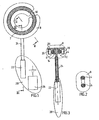
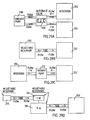
- Figs. 1-3 show a preferred embodiment of the food intake restriction device of the invention comprising a restriction member in the form of a circular resilient core 2 with two overlapping end portions 4,6.
- the core 2 defines a substantially circular restriction opening and is enclosed in an elastic soft hose 8 except at a releasable and lockable joint 10 of the core 2, which when released enables application of the core 2 with its hose 8 around the esophagus or the stomach of a patient.
- the materials of all of these elements are bio-compatible so that the patient's body will not reject them.
- a post-operation mechanical adjustment means 12 for mechanically adjusting the longitudinal extension of the core 2 to change the size of the restriction opening comprises a drive wheel 14 in frictional engagement with the overlapping end portions 4,6 of the core 2.
- the drive wheel 14 is journalled on a holder 16 placed in the hose 8 and provided with two counter pressure rollers 18,20 pressing the respective end portions 4, 6 of the core 2 against the drive wheel 14 to increase the frictional engagement therebetween.
- An electric motor 22 is connected to the drive wheel 14 via a long flexible drive shaft 24 and is moulded together with a remote controlled power supply unit 26 in a body 28 of silicone rubber.
- the length of the flexible drive shaft 34 is selected so that the body 28 can be placed in a desired position in the patient's body, suitably in the abdomen.
- the power supply unit 26 is controlled to power the electric motor 22 either to turn the drive wheel 14 in one direction to reduce the diameter of the core 2 or to turn the drive wheel 14 in the opposite direction to increase the diameter of the core 2.
- a rack gear may be formed on one of the end portions 4,6 of the core 2 and the drive wheel 14 may be replaced by a drive gear wheel connected to the other end portion of the core 2 and in mesh with the rack gear.
- Fig.4 shows an embodiment of the invention which is identical to the embodiment of Figs. 1-3, except that the motor 22 is encapsulated in a lateral protrusion 30 of the hose 8 so that it is fixed to the core 2 and has a short drive shaft 32 onto which the drive wheel 14 is mounted, the motor 22 being positioned relative to the circular core 2 such that the drive shaft 32 extends radially thereto.
- Fig. 5 shows an embodiment of the invention which likewise is identical to the embodiment of Figs. 1-3, except that the motor 22 is encapsulated in the hose 8 so that it is fixed to the core 2 and has a short drive shaft 32, the motor 22 being positioned relative to the core 2 such that the drive shaft 32 extends substantially tangentially to the circular core 2. There is an angular gearing 34 connecting the drive shaft 32 to the drive wheel 14.
- Fig. 6 shows a suitable arrangement for the motor 22 in the embodiment of Fig. 5, comprising a first clamping member 36 secured to one end portion of the core 2 and a second clamping member 38 secured to the other end portion 6 of the core 2.
- the motor 22 is secured to the first clamping member 36 and is operatively connected to a worm 40 via a gear transmission 42.
- the worm 40 is journalled at its opposite ends on holders 44 and 46, which are rigidly secured to the clamping member 36 and the motor 22, respectively.
- the second clamping member 38 has a pinion in mesh with the worm 40.
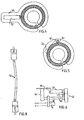
- Fig. 7 shows another device in which a restriction member comprises an elongated core 48 and a helical spring 50.
- a spring contracting means in the form of a flexible pulling member 52 i.e. a string, wire or cable, is connected to the core 48 at one end thereof and extends through the helical spring 50.
- a hydralic motor in the form of a cylinder/piston unit 54 is adapted to pull the flexible pulling member 52 to contract the helical spring 50 against an arresting member 56, which is fixed relative to the core 48.
- FIG. 8 shows a similar embodiment in which a hydraulic transmission conduit 59 is provided between two piston-cylinder assemblies 54, for use as the hydraulic motor/device in Fig. 7.
- Fig. 9 shows another device in which the restriction member comprises two elongated helical springs 60 and 62 having free ends, and a body 64 to which the springs 60,62 are nonrotatably secured at their opposite ends.
- the body 64 comprises two separate parts secured to opposite end portions of the enclosing elastic hose 8 and is designed with a releasable and lockable joint between the separate parts.
- An adjustment means in the form of a drive shaft 66 has two opposite end portions connected to the helical springs 60,62, respectively, at their free ends.
- the coils of the springs 60,62 form left and right hand helices, respectively.
- a motor 68 is adapted to rotate the drive shaft 66 in one direction to enlarge the coils of the helical springs 60,62 to longitudinally contract the springs 60,62 and to rotate the drive shaft 66 in the opposite direction to reduce the size of the coils of the springs 60,62 to longitudinally extend the springs 60,62.
- the elongated helical springs 60,62 defines a restriction opening, the size of which is increased when the springs 60,62 are extended and decreased when the springs 60.62 are contracted.
- Fig. 10 shows a device which is identical to the device of Fig.9, except that the adjustment means comprises a gearing having an input shaft 72 and two opposite aligned output shafts 74 and 76 connected to the helical springs 60 and 62, respectively, at their free ends.
- the input shaft 72 is connected to the output shafts 74,76 such that they rotate at opposite directions upon rotation of the input shaft 72.
- the coils of the springs 60, 62 form the same helices.
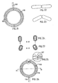
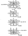
- Figs. 11-14 show a device in which a hydraulic motor comprises two interconnected cylinders 78 and 80 and two pistons 82 and 84 in the respective cylinders 78,80.
- the cylinders 78,80 have a common fluid supply inlet member 86, which together with the cylinders 78,80 takes the shape of a Y-pipe.
- the restriction member comprises an elongated resilient arcuate core 88.
- the adjustment means comprises two bars 90 and 92 secured to opposite ends of the core 88 and connected to the pistons 82 and 84, respectively.
- the core 88 defines a restriction opening and is provided with a releasable and lockable joint 94 (Fig. 13) to permit application of the core 88 around the esophagus or stomach.
- the core 88 and the cylinders 90,92 are enclosed by a soft elastic hose 96 except at the joint 94 and the inlet member 86.
- the hose 96 has an outer tubular wall 98 and a central coaxial inner tubular wall 100, which is fixed to the outer wall 98 by spoke members 102 (Fig. 14).
- the core 88. is loosely fit in the inner tubular wall 100.
- Figs. 15-17 show a device which is identical to the device of Figs. 11-14, except that the adjustment means comprises an elongated voltage responsive element 104 secured to the opposite ends of the core 88, so that the core 88 and the element 104 form the restriction member.
- the element 104 is capable of bending inwardly into a bow in response to a voltage applied across the element 104.
- the radius of curvature of said bow is adjustable by changing the level of the voltage applied to element 104.
- Fig. 18 shows a device comprising a loop forming means in the form of a substantially rigid outer circular element 106 with a releasable and lockable joint 108 to enable application of the device around the esophagus or stomach.
- the restriction member comprises an elastic inner circular element 110 formed by the innermost wall portion of an elastic hose 112 extending along the outer element 106.
- the inner circular element 110 is disposed concentrically within the outer circular element 106.
- the adjustment means comprises a plurality of threads 114 secured to the elastic inner element 110 along the circumference thereof and running from the inner element 110 via guide members 116 attached to the outer element 106. By pulling all the threads 114 the inner elastic element 110 is pulled under expansion radially outwardly towards the outer element 106.
- Fig. 19 shows a device which is identical to the device of Fig, 9, except that it comprises a loop forming means in the form of a substantially rigid outer circular element 118 supporting the helical springs 60,62, and a soft elastic inner wall 120 extending along the springs 60,62.
- the motor 68 rotates the helical springs 60, 62 in a direction that enlarges the coils of the springs 60,62, the coils are forced by the rigid outer element 118 to expand radially inwardly thereby reducing the size of the restriction opening formed by the circumferential confinement surface of the restriction member (springs 60, 62 and body 64).
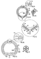
- Fig. 20 shows a further device in which a restriction member comprises a plurality of arcuate lamellae 122 arranged like the conventional adjustable aperture mechanism of a camera.
- the adjustment means is conventional and is operated by a motor 124 to adjust the lamellae 122 to change the size of an restriction opening defined by the lamellae 122.
- Figs. 21-23 show a device in which a restriction member comprises two semi-circular elements 126 and 128 which are hinged together such that the semi-circular elements 126,128 are swingable relative to each other between a fully open state in which they substantially form a circle, illustrated in Fig, 22 and an angular state, in which the size of the restriction opening defined by the semi-circular elements 126,128 is reduced, illustrated in Fig. 23.
- the adjustment means is conventional and is operated by a motor 130 to swing the semi-circular elements 126,128 relative to each other.
- Figs. 24-27 show a device in which the restriction member comprises an elastic belt 130 forming a circle and having a substantially oval cross-section.
- the restriction member 130 is provided with a releasable and lockable joint 132.
- An elastic double walled hose 134 encloses the belt 130 except at the joint 132.
- the adjustment means is conventional and is operated by a motor 136 to turn the belt 130 around the longitudinal extension thereof between a fully open state, in which the inner broader side of the belt 130 forms a substantially cylindrical surface, illustrated in Fig. 26, and a reduced open state, in which the inner broader side of the belt 130 forms a substantially conical surface, illustrated in Fig. 27.
- Fig. 28 schematically illustrates a cushion arrangement for protecting the esophagus or stomach, comprising a plurality of cushions 138 disposed in series along a substantially circular holding member 140.
- This cushion arrangement may be utilized in any of the above described devices.
- Figs. 29A-D provide a block diagram of four different hydraulic transmission configurations.
- Fig. 29A shows an adjustment means 202 of the restriction member, a separate reservoir 204, a one way pump 206 and an alternate valve 208.
- Fig. 29B shows the adjustment means 202 and an adjustable reservoir 210.
- Fig. 29C shows the adjustment means 202, a two way pump 212 and the reservoir 204.
- Fig. 30D shows a servo system with a first closed system controlling a second system.
- the servo system comprises the adjustable reservoir 210 and a passive adjustable reservoir 214. Any of the reservoirs can be the active reservoir, either the servo reservoir 210 or the fluid supply reservoir 214.
- the reservoir 214 controls a larger adjustable reservoir 216 which is used for the operation of the adjustment means 202 for changing the restriction opening of the restriction member.
- Figs. 30A-D are cross-sectional views of a pump mechanism adapted to pump fluid in both directions only by mechanically pushing a separate sealing wall portion 218 in one direction.
- Fig 30A shows a piston 220 pushed forwards against a spring 222 towards the wall portion 218 and located in a pump housing 224 conducting fluid from a right upper fluid passage 226 of the housing 224 to a left fluid passage 228 of the housing 224.
- a main valve 230 is open and a nonreturn valve 232 is closed.
- Fig. 30B illustrates the first pump movement in which the piston 220 has moved forwards and reaches the wall portion 218.
- Fig. 30C illustrates how the piston 220 moves backwards by the action of the spring 222.
- Fig. 30D illustrates how the piston 220 is moved further downwards from its position according to Fig. 30B while pushing the wall portion 218 downwards against a second spring 234 that is stronger than spring 222, so that fluid escapes from a right lower fluid passage 236.
- a second spring 234 that is stronger than spring 222
- Fig 31 is a cross-sectional view of a reservoir 240 defining a chamber 242, the size of which is variable and is controlled by a remote controlled motor 244, in accordance with Fig. 29B or 29D.
- the reservoir 240 and the motor 244 are placed in a housing 246.
- the chamber 242 is varied by moving a large wall 248.
- the wall 248 is secured to a nut 250, which is threaded on a rotatable spindle 252.
- the spindle 252 is rotated by the motor 244 via an angular gearing, which comprises two conical gear wheels 254 and 256 in mesh with each other.
- the motor 244 is powered by a battery 258 placed in the housing 246.
- a signal receiving means 260 for controlling the motor 244 is also placed in the housing 246.
- the battery 258 and the signal receiving means 260 may be mounted in a separate place.
- the signal receiving means may comprise any known or conventional device which is capable of receiving a control signal and then operating the motor 244.
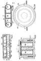
- Fig. 32 is a cross-sectional view of a reservoir 262 defining a chamber 264, the size of which is variable and is controlled by manual manipulation.
- a gable wall portion 266 of an open ended inner cylindrical housing 68 is adapted to be pushed downwards to fit in a desired locking groove 270 of a plurality of locking grooves 270 on the mantle wall of the cylindrical housing 268, to reduce the size of the chamber 64.
- the inner cylindrical housing 268 is suspended by springs 272 and is telescopically applied on an outer cylindrical housing 274. When pushing the inner cylindrical housing 268 it moves downwards relative to the outer cylindrical housing 274 causing the gable wall portion 266 to release from the locking groove 270 and move upwards relative to the inner cylindrical housing 268.
- the inner housing 268 is moved upwardly by the action of the springs 272 the size of the chamber 264 is increased.
- Fig. 33A and 33B show a servo means comprising a main ring-shaped fluid reservoir 276 defining a chamber 278, the size of which is variable. Centrally positioned in the main ring-shaped reservoir 276 there is a servo fluid reservoir 280 defining a chamber 282, the size of which is variable.
- the chamber 282 of the servo reservoir 280 is significantly smaller than the chamber 278 of the main reservoir 276.
- the two reservoirs 276 and 280 are situated between two opposite separate walls 284 and 286, and are secured thereto. When changing the amount of fluid in the servo reservoir 280, the two opposite walls 284,286 are moved towards or away from each other, whereby the size of the chamber 278 of the main reservoir 276 is changed.
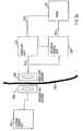
- Fig. 34 shows the basic parts of a remote control system of the implantable device of the invention including a motor, for instance the electric motor 22.
- the remote control system is based on the transmission of electromagnetic wave signals, often of high frequencies in the order of 100 kHz - 1 gHz, through the skin 330 of the patient.
- all parts placed to the left of the skin 330 are located outside the patient's body and all parts placed to the right of the skin 330 are implanted in the patient's body.
- An external signal transmitting antenna 332 is to be positioned close to a signal receiving antenna 334 implanted in the patient's body close to the skin 330.
- the receiving antenna 334 may be placed for example inside the abdomen of the patient.
- the receiving antenna 334 comprises a coil, approximately 1-100 mm, preferably 25 mm in diameter, wound with a very thin wire and tuned with a capacitor to a specific high frequency.
- a small coil is chosen if it is to be implanted under the skin of the patient and a large coil is chosen if it is to be implanted in the abdomen of the patient.
- the transmitting antenna 332 comprises a coil having about the same size as the coil of the receiving antenna 334 but wound with a thick wire that can handle the larger currents that is necessary.
- the coil of the transmitting antenna 332 is tuned to the same specific high frequency as the coil of the receiving antenna 334.
- An external control unit 336 comprises a microprocessor, a high frequency electromagnetic signal generator and a power amplifier.
- the microprocessor of the control unit 336 is adapted to switch on/off the generator and to modulate signals generated by the generator to send digital information via the power amplifier and the antennas 332,334 to an implanted control unit 338.
- digital signal codes are used.
- a keypad placed on the external control unit 336 is connected to the microprocessor thereof. The keypad is used to order the microprocessor to send digital signals to either increase or decrease the size of the restriction opening defined by the loop of the restriction member (e.g. as described above).
- the microprocessor starts a command by applying a high frequency signal on the antenna 332.
- commands are sent to increase or decrease the size of the restriction opening of the restriction member in predefined steps.
- the commands are sent as digital packets in the form illustrated below. Start pattern, 8 bits Command, 8 bits Count, 8 bits Checksum, 8 bits
- the commands are sent continuously during a rather long time period (e.g. 30 seconds or more).
- a rather long time period e.g. 30 seconds or more.
- an implanted energizer unit 326 draws energy from the high frequency electromagnetic wave signals received by the receiving antenna 334.
- the energizer unit 326 stores the energy in a power supply, such as a large capacitor, powers the control unit 338 and powers the electric motor 22 via a line 342.
- the control unit 338 comprises a demodulator and a microprocessor.
- the demodulator demodulates digital signals sent from the external control unit 336.
- the microprocessor of the control unit 338 receives the digital packet, decodes it and, provided that the power supply of the energizer unit 326 has sufficient energy stored, sends a signal via a signal line 344 to the motor 22 to either increase or decrease the size of the restriction opening of the restriction member depending on the received command code.
- the energy stored in the power supply of the energizer unit may only be used for powering a switch, and the energy for powering the motor 22 may be obtained from another implanted power source of relatively high capacity, for example a battery.
- the switch is adapted to connect the battery to the control unit 338 in an "on" mode when said switch is powered by said power supply and to keep said battery disconnected from the control unit in a "standby" mode when the switch is unpowered.
- the external control unit 336 comprises a microprocessor 346, a signal generator 348 and a power amplifier 350 connected thereto.
- the microprocessor 346 is adapted to switch the signal generator 348 on/off and to modulate signals generated by the signal generator 348 with digital commands that are sent to implanted components of the device of the invention.
- the power amplifier 350 amplifies the signals and sends them to the external signal transmitting antenna 332.
- the antenna 332 is connected in parallel with a capacitor 352 to form a resonant circuit tuned to the frequency generated by the signal generator 348.
- the implanted signal receiving antenna coil 334 forms together with a capacitor 354 a resonant circuit that is tuned to the same frequency as the transmitting antenna 332.
- the signal receiving antenna coil 334 induces a current from the received high frequency electromagnetic waves and a rectifying diode 360 rectifies the induced current, which charges a storage capacitor 358.
- a coil 356 connected between the antenna coil 334 and the diode 360 prevents the capacitor 358 and the diode 360 from loading the circuit of the signal receiving antenna 334 at higher frequencies.
- the coil 356 makes it possible to charge the capacitor 358 and to transmit digital information using amplitude modulation.
- a capacitor 362 and a resistor 364 connected in parallel and a diode 366 forms a detector used to detect amplitude modulated digital information.
- a filter circuit is formed by a resistor 368 connected in series with a resistor 370 connected in series with a capacitor 372 connected in series with the resistor 368 via ground, and a capacitor 374, one terminal of which is connected between the resistors 368,370 and the other terminal of which is connected between the diode 366 and the circuit formed by the capacitor 362 and resistor 364.
- the filter circuit is used to filter out undesired low and high frequencies.
- the detected and filtered signals are fed to an implanted microprocessor 376 that decodes the digital information and controls the motor 22 via an H-bridge 378 comprising transistors 380,382,384 and 386.
- the motor 22 can be driven in two opposite directions by the H-bridge 378.
- the microprocessor 376 also monitors the amount of stored energy in the storage capacitor 358. Before sending signals to activate the motor 22, the microprocessor 376 checks whether the energy stored in the storage capacitor 358 is enough. If the stored energy is not enough to perform the requested operation, the microprocessor 376 waits for the received signals to charge the storage capacitor 358 before activating the motor 22.
- control unit may be replaced by discrete components.
- the power amplifier of the external control unit may be omitted if the signals generated by the signal generator are strong enough. Therefore the invention is to be accorded the broadest interpretation of the appended claims to encompass all equivalent structures and assemblies.
- One further advantage with this invention is that there may be a night button on the remote control setting the adjustment means in a position with a larger stoma diameter during the night, thus avoiding vomiting or nausa.
Abstract
Description
- The present invention relates to a food intake restriction device for forming a stoma opening in the stomach or esophagus of a patient, the device comprising an elongated restriction member, forming means for forming the elongated restriction member into at least a substantially closed loop around the stomach or esophagus, said loop defining a restriction opening, and an adjustment means for adjusting the restriction member in said loop to change the size of said restriction opening. The term "patient" includes an animal or a human being. A device according to the preamble of
claim 1 is disclosed inWO-A-99/63907 - Food intake restriction devices in the form of gastric banding devices, in which a band encircles a portion of a patient's stomach to restrict the food intake of the patient, have been used in surgery for morbid obesity to form a small gastric pouch above the band and a reduced stoma opening in the stomach. Although such a band is applied around the stomach to obtain an optimal stoma opening during surgery, some prior gastric banding devices are provided with an adjustment means enabling a minor post-operation adjustment of the size of the stoma opening. In all such prior art devices such as disclosed in
U.S. Patent No. 4,592,339 ,European Patent No. 0611561 andInternational Patent Application WO 94/27504 - It has been found, however, that the bands of this type of prior art devices used for forming a stoma opening in a patient's stomach may eventually dislocate downwardly on the stomach and there is an increased risk of stoma stenosis due to a small range of adjustment of the band. It has also been found that the volume of the gastric pouch above the band increases in size up to ten times after operation. Therefore the pouch volume during surgery needs to be very small, approximately 7 ml. To enable the patient to feed the stomach with sufficient nutrition immediately after an operation considering such a small gastric pouch, the stoma initially needs to be relatively large and later needs to be substantially reduced, as the pouch volume increases. To be able to achieve a significant range of adjustment of the band, the cavity in the band has to be relatively large and is defined by a thin flexible wall, normally made of silicone material. Furthermore, the size of the stoma opening has to be gradually reduced during the first year after surgery as the gastric pouch increases in size. As indicated above, the reduction of the stoma opening using the prior art devices is achieved by adding liquid to the cavity of the band via the injection port to expand the band radially inwardly.
- A great disadvantage of repeatedly injecting liquid via the injection port is the increased risk of the patient getting an infection in the body area surrounding the injection port. If such an infection occurs the injection port has to be surgically removed from the patient. Moreover, such an infection might be spread along the tube interconnecting the injection port and the band to the stomach, causing even more serious complications. Thus, the stomach might be infected where it is in contact with the band, which might result in the band migrating through the wall of the stomach. Also, it is uncomfortable for the patient when the necessary, often many, post-operation adjustments of the stoma opening are carried out using an injection needle penetrating the skin of the patient into the injection port.
- It may happen that the patient swallows pieces of food too large to pass through the restricted stoma opening. If that occurs the patient has to visit a doctor who can remove the food pieces, if the band design so permits, by withdrawing some liquid from the band to enlarge the stoma opening to allow the food pieces to pass the stoma. Then, the doctor has to add liquid to the band in order to regain the restricted stoma opening. Again, these measures require the use of an injection needle penetrating the skin of the patient, which is uncomfortable for the patient.
- Another problem with known adjustable gastric banding devices is that isotonic salt solution can diffuse from the inflatatle cavity of the band through the surrounding band walls of silicone rubber when there is a slight overpressure prevailing in the cavity. There is also a risk some time after the operation of liquid leakage from the injection port, from the tube between the latter and the band, and from the band itself. Most critical is the inflatable balloon cavity.
- An object of the present invention is to provide a food intake restriction device in which the risk of liquid leaking from the device within the patient's body is substantially reduced or eliminated.
- Another object of the invention is to provide a food intake restriction device which does not require the use of an injection needle for accomplishing post-operation adjustments of the stoma opening.
- Yet another object of the invention is to provide a food intake restriction device which permits post-operation adjustments that are comfortable for the patient.
- These objects are obtained by a food intake restriction device of the kind stated initially, which is characterised in that the adjustment means is designed to mechanically adjust the restriction member in a non-invasive manner to allow post-operation non-invasive adjustments of the restriction member. As a result, there is no liquid directly involved in the elongated restriction member itself for providing inflation thereof, enabling post-operation adjustments of the device of the invention to change the stoma opening of the patient. The adjustment means may be incorporated in the restriction member as well as being controlled by hydraulic means. The expression "post-operation non-invasive adjustment means" means that the adjustment means is capable of adjusting the restriction member after the operation without the need for invasive measures, such as penetration of the skin for example by injection needles or surgery, or by any other means that penetrate the skin. Though an injection port could be used in embodiments using hydraulic means, the port preferably would be for enabling a single, once and for all, calibration of the amount of liquid contained by the hydraulic means.
- In accordance with a preferred first adjustment principle, the adjustment means is adapted to adjust the longitudinal extension of the elongated restriction member in a loop form.
- In a preferred embodiment of the invention utilizing the first adjustment principle, the restriction member comprises a main portion and two elongated end portions, and the adjustment means is adapted to establish longitudinal relative displacement between the end portions of the restriction member, so that the size of the restriction opening is adjusted. The forming means may comprise any suitable known or conventional device capable of practicing the desired function, such as a spring material forming the elongated restriction member into the loop, so that the restriction opening has a predetermined size, and the adjustment means may be adapted to adjust the restriction member against the spring action of the spring material. In other words, the restriction member may comprise a spring clip. The spring material may be integrated in the restriction member.
- Preferably, the adjustment means comprises a movement transferring member, suitably a drive wheel, in engagement with at least one of the end portions of the restriction member and operable to displace said one end portion relative to the other end portion of the restriction member. The drive wheel may advantageously be in engagement with both of the end portions of the restriction member and be operable to displace said end portions relative to each other. An elongated flexible drive shaft may be operatively connected to the drive wheel, for transferring manual or motor generated power from a location remote from the restriction member. In its simplest embodiment, the drive wheel may comprise a pulley in frictional engagement with the restriction member. As an alternative, a gear rack may be formed on at least one of the end portions of the restriction member and the drive wheel may comprise a gear wheel in mesh with the gear rack. Other suitable known or conventional mechanisms may also or alternatively be used as the adjustment means.
- The movement transferring member may alternatively comprise at least one cylinder and a piston, which is movable therein and is connected to one of the end portions of the restriction member, the piston being operable to longitudinally displace said one end portion of the restriction member relative to the other end portion of the restriction member. Alternatively, the movement transferring means may comprise two interconnected cylinders and two pistons in the respective cylinders connected to said end portions, respectively, of the restriction member, the pistons being operable to longitudinally displace the end portions of the restriction member relative to each other. Other known or conventional devices also or alternatively can be used as the movement transferring member.
- A motor, which is fixed relative to the main portion of the restriction member and has a rotating drive shaft operatively connected to the movement transferring member, may be positioned relative to the elongated restriction member such that the drive shaft extends transverse thereto. Alternatively, the motor may be positioned relative to the elongated restriction member such that the drive shaft extends substantially tangentially to the loop of the restriction member.
- In all of the above-described embodiments of the invention the adjustment means is conveniently operated by any suitable motor, preferably an electric motor, which may be fixed directly to or be placed in association with the restriction member, or alternatively be located remote from the restriction member, advantageously in the abdomen or subcutaneously. In the latter alternative the motor is advantageously connected to the adjustment means by a flexible power transmission conduit to permit a suitable positioning of the motor in the abdomen of the patient. The motor may be manually activatable, for example by an implanted switch.
- All solutions may be controlled by a wireless remote control means for non-invasively controlling the adjustment means. The remote control means may advantageously be capable of obtaining information on the size of the restriction opening and to command the adjustment means to adjust the restriction member in response to obtained information.
- The remote control means comprises means for wireless transfer of energy from outside the patient's body to energy consuming implantable components of the device. An implantable motor may suitably be provided for operating the adjustment means and said means for wireless transfer of energy may be adapted to directly power the motor with transferred energy. The energy transferred by said means for transfer of energy may comprise wave signals, an electric field or a magnetic field.
- Preferably, the wireless remote control means comprises separate signal transmitting means and implantable signal receiving means. For example, the signal transmitting and signal receiving means may be adapted to transmit and receive signals in the form of digital pulses, which may comprise a magnetic or electric field. Alternatively, which is preferred, the signal transmitting and signal receiving means may be adapted to transmit and receive signals, which may comprise electromagnetic waves, sound waves or carrier waves for remote control signals. The receiving means may comprise a control unit adapted to control the adjustment means in response to signals from the signal transmitting means.
- The food intake restriction device may further comprise an implantable energizer unit for providing energy to energy consuming components of the device to be implanted in the patient, such as electronic circuits and/or a motor for operating the adjustment means. The control unit may be adapted to power such an implanted motor with energy provided by the energizer unit in response to signals received from the signal transmitting means. Any known or conventional signal transmitting or signal receiving device that is suitable for use with a human or mammal patient may be provided as the signal transmitting or signal receiving means. The signals may comprise electromagnetic waves, such as infrared light, visible light, laser light, micro waves, or sound waves, such as ultrasonic waves or infrasonic waves, or any other type of wave signals. The signals may also comprise electric or magnetic fields, or pulses. All of the above-mentioned signals may comprise digital signals.
- The motor may be any type of motor, such as a pneumatic, hydraulic or electric motor and the energizer unit may be adapted to power the motor with pressurized gas or liquid, or electrical energy, depending on the type of motor. Where the motor is an electric motor, it may power pneumatic or hydraulic equipment.
- The energizer unit may comprise a power supply and the control unit may be adapted to power the motor with energy from the power supply. Preferably, the power supply is an electric power supply, such as a battery, and the motor is an electric motor. In this case, the battery also continuously powers the circuitry of the signal receiving means between the adjustment operations, in order to keep the signal receiving means prepared for receiving signals transmitted from the signal transmitting means.
- Ihe energizer unit may be adapted to transfer energy from the signals, as they are transmitted to the signal receiving means, into electric energy for powering the implanted electronic components. For example, the energizer unit may be adapted to transfer the energy from the signals into direct or alternating current.
- In case there is an implanted electric motor for operating the adjustment means the energizer unit may also power the motor with the transferred energy. Advantageously, the control unit is adapted to directly power the electric motor with electric energy, as the energizer unit transfers the signal energy into the electric energy. This embodiment is particularly simple and does not require any recurrent invasive measures for exchanging empty power supplies, such as batteries, that is required in the first embodiment described above.
- For adjustment means of the type that requires more, but still relatively low, power for its operation, the energizer unit may comprise a rechargeable electric power supply for storing the electric energy obtained and the control unit be adapted to power the electric motor with energy from the rechargeable electric power supply in response to signals received from the signal transmitting means. In an initial charging step the rechargeable power supply can be charged over a relatively long time (e.g. a few seconds up to a half hour) without powering the electric motor. In a following operating step, when the power supply has been charged with sufficient energy, the control unit powers the electric motor with energy from the charged power supply to operate the adjustment means, so that a desired change of the patient's stoma opening is achieved. If the capacity of the power supply is insignificant to achieve the necessary adjustment in one single operating step, the above steps may conveniently be repeated until the desired adjustment is achieved.
- The electric power supply suitably comprises an inexpensive simple capacitor. In this case, the electric motor may be a stepping motor.
- The signal transmitting means may be adapted to transmit electromagnetic signals and the energizer unit be adapted to draw radiant energy from the electromagnetic wave signals, as they are transmitted to the signal receiving means, and transfer the radiant energy into electric energy.
- Alternatively, the energizer unit may comprise a battery, an electrically operable switch adapted to connect the battery to the signal receiving means in an "on" mode when the switch is powered and to keep the battery disconnected from the signal receiving means in a "standby" mode when the switch is unpowered, and a rechargeable electric power supply for powering the switch. The control unit may be adapted to power the electric motor with energy from the battery in response to signals received from the signal transmitting means, when the switch is in its "on" mode. Advantageously, the energizer unit may be adapted to transfer wave energy from the signals, as they are transmitted to the signal receiving means, into a current for charging the rechargeable electric power supply, which suitably is a capacitor. Energy from the power supply is then used to change the switch from "off" (standby mode) to "on". This embodiment is suited for adjustment means of the type that require relatively high power for their operation and has the advantage that the electronic circuitry of the signal receiving means does not have to be powered by the battery between adjustment operations. As a result, the life-time of the battery can be significantly prolonged.
- As an example, the signal transmitting means may be adapted to transmit electromagnetic wave signals and the energizer unit be adapted to draw radiant energy from the electromagnetic wave signals, as they are transmitted to the signal receiving means, and to transfer the radiant energy into said current. The energizer unit suitably comprises a coil of the signal receiving means for inducing an alternating current as electromagnetic wave signals are transmitted through the coil and a rectifier for rectifying the alternating current. The rectified current is used for charging the rechargeable power source.
- Alternatively, the signal transmitting and receiving means may solely be used for control signals and further signal transmitting and receiving means be provided for transferring signal energy to implanted components. By such a double system of signal transmitting and receiving means the advantage is obtained that the two systems can be designed optimally for their respective purposes, namely to transmit control signals and to transfer energy from signals.
- As should be realized by a skilled person, in many of the above-described embodiments of the invention the adjustment means may be operated by control means or manual manipulation means implanted under the skin of the patient, such as a pump, an electrical switch or a mechanical movement transferring means. In the manual embodiment it is not necessary to use a motor for operating the adjustment means.
- In embodiments including hydraulic transmission means, an injection port connected to the hydraulic means may be provided for enabling, normally single, once-and-for-all, calibration of the amount of fluid in the hydraulic system.
- The invention will now be described in more detail with reference to the accompanying drawings, in which:
- Fig. 1 is a schematic sectional view of a preferred first embodiment of the food intake restriction device in accordance with the invention;
- Figs. 2 and 3 are cross-sectional views taken along the lines II-II and III-III, respectively, of Fig. 1;
- Figs. 4 and 5 schematically show two alternative designs of the embodiment of Fig.1;
- Fig. 6 schematically illustrates a motor arrangement for the design according to Fig. 5;
- Fig. 7 is a schematic sectional view of another device;
- Fig. 8 schematically illustrates a hydraulic transmision conduit for the device of Fig. 7;
- Fig. 9 is a schematic sectional view of a further device
- Fig. 10 is a modification of the device of Fig. 9;
- Fig. 11 is a schematic view of a further device;
- Figs. 12 and 13 are enlarged details of the device of Fig. 11;
- Fig. 14 is a cross-section along the line XIV-XIV of Fig. 11;
- Fig. 15 is a schematic view of another device;
- Fig. 16 is an enlarged detail of Fig. 15;
- Fig. 17 is a cross-section along the line XVII-XVII of Fig. 15;
- Figs. 18 to 21 are schematic sectional views of further devices;
- Figs. 22 and 23 illustrate a fully open and a reduced restriction opening, respectively, of the device of Fig. 21;
- Fig. 24 is a schematic view of a further device;
- Fig. 25 is an enlarged detail of the device of Fig. 24;
- Figs. 26 and 27 illustrate a fully open and a reduced restriction opening, respectively, of the device of Fig. 24;
- Fig. 28 schematically illustrates a cushion arrangement for protecting the stomach or esophagus of the patient;
- Fig. 29A-D is a block diagram of four different principal devices;
- Fig. 30A-D are cross-sectional views of a pump mechanism according to Fig. 29C, which pumps fluid in opposite directions by mechanically pushing a wall portion in only one direction;
- Fig. 31 is a cross-sectional view of a reservoir having a variable volume controlled by a remote control motor, in accordance with a device shown in Fig. 29B or 30B;
- Fig. 32 is a cross-sectional view of a a reservoir having a variable volume adjustable by manual manipulation, in accordance with a device shown in Fig. 29B or 29D;
- Fig. 33A is a front view of a hydraulic, pneumatic or mechanical servo system in accordance with a device shown in Fig. 29D;
- Fig 33B is a cross-sectional view taken along line VB-VB of Fig 33A;
- Fig. 34 is a block diagram illustrating remote control components and
- Fig. 35 is a schematic view of a circuitry used for the system of the block diagram of Fig.34.
- Referring to the drawing figures, like reference numerals designate identical or corresponding elements throughout the several figures.
- Figs. 1-3 show a preferred embodiment of the food intake restriction device of the invention comprising a restriction member in the form of a circular
resilient core 2 with two overlapping end portions 4,6. Thecore 2 defines a substantially circular restriction opening and is enclosed in an elasticsoft hose 8 except at a releasable and lockable joint 10 of thecore 2, which when released enables application of thecore 2 with itshose 8 around the esophagus or the stomach of a patient. The materials of all of these elements are bio-compatible so that the patient's body will not reject them. A post-operation mechanical adjustment means 12 for mechanically adjusting the longitudinal extension of thecore 2 to change the size of the restriction opening comprises adrive wheel 14 in frictional engagement with the overlapping end portions 4,6 of thecore 2. Thedrive wheel 14 is journalled on aholder 16 placed in thehose 8 and provided with twocounter pressure rollers core 2 against thedrive wheel 14 to increase the frictional engagement therebetween. Anelectric motor 22 is connected to thedrive wheel 14 via a longflexible drive shaft 24 and is moulded together with a remote controlledpower supply unit 26 in abody 28 of silicone rubber. The length of theflexible drive shaft 34 is selected so that thebody 28 can be placed in a desired position in the patient's body, suitably in the abdomen. - If some time after the operation the patient needs an adjustment of the restriction opening of the
core 2, thepower supply unit 26 is controlled to power theelectric motor 22 either to turn thedrive wheel 14 in one direction to reduce the diameter of thecore 2 or to turn thedrive wheel 14 in the opposite direction to increase the diameter of thecore 2. - Alternatively, a rack gear may be formed on one of the end portions 4,6 of the
core 2 and thedrive wheel 14 may be replaced by a drive gear wheel connected to the other end portion of thecore 2 and in mesh with the rack gear. - Fig.4 shows an embodiment of the invention which is identical to the embodiment of Figs. 1-3, except that the
motor 22 is encapsulated in alateral protrusion 30 of thehose 8 so that it is fixed to thecore 2 and has ashort drive shaft 32 onto which thedrive wheel 14 is mounted, themotor 22 being positioned relative to thecircular core 2 such that thedrive shaft 32 extends radially thereto. - Fig. 5 shows an embodiment of the invention which likewise is identical to the embodiment of Figs. 1-3, except that the
motor 22 is encapsulated in thehose 8 so that it is fixed to thecore 2 and has ashort drive shaft 32, themotor 22 being positioned relative to thecore 2 such that thedrive shaft 32 extends substantially tangentially to thecircular core 2. There is anangular gearing 34 connecting thedrive shaft 32 to thedrive wheel 14. - Fig. 6 shows a suitable arrangement for the
motor 22 in the embodiment of Fig. 5, comprising a first clamping member 36 secured to one end portion of thecore 2 and asecond clamping member 38 secured to the other end portion 6 of thecore 2. Themotor 22 is secured to the first clamping member 36 and is operatively connected to aworm 40 via agear transmission 42. Theworm 40 is journalled at its opposite ends onholders motor 22, respectively. Thesecond clamping member 38 has a pinion in mesh with theworm 40. When themotor 22 is powered theworm 40 rotates and will thereby pull the end portion 6 of thecore 2 in one or the opposite longitudinal direction, so that the diameter of the substantiallycircular core 2 is either increased or decreased. - Fig. 7 shows another device in which a restriction member comprises an
elongated core 48 and ahelical spring 50. A spring contracting means in the form of a flexible pullingmember 52, i.e. a string, wire or cable, is connected to the core 48 at one end thereof and extends through thehelical spring 50. A hydralic motor in the form of a cylinder/piston unit 54 is adapted to pull the flexible pullingmember 52 to contract thehelical spring 50 against an arrestingmember 56, which is fixed relative to thecore 48. Atube 58 hinged to the arrestingmember 56 extends between the cylinder/piston unit 54 and the arrestingmember 56, the flexible pullingmember 52 running through thetube 58 and being connected to the piston of the cylinder/piston unit 54. Fig. 8 shows a similar embodiment in which a hydraulic transmission conduit 59 is provided between two piston-cylinder assemblies 54, for use as the hydraulic motor/device in Fig. 7. - Fig. 9 shows another device in which the restriction member comprises two elongated
helical springs body 64 to which thesprings body 64 comprises two separate parts secured to opposite end portions of the enclosingelastic hose 8 and is designed with a releasable and lockable joint between the separate parts. An adjustment means in the form of adrive shaft 66 has two opposite end portions connected to thehelical springs springs motor 68 is adapted to rotate thedrive shaft 66 in one direction to enlarge the coils of thehelical springs springs drive shaft 66 in the opposite direction to reduce the size of the coils of thesprings springs helical springs springs - Fig. 10 shows a device which is identical to the device of Fig.9, except that the adjustment means comprises a gearing having an
input shaft 72 and two opposite alignedoutput shafts helical springs input shaft 72 is connected to theoutput shafts input shaft 72. The coils of thesprings - Figs. 11-14 show a device in which a hydraulic motor comprises two
interconnected cylinders pistons respective cylinders cylinders supply inlet member 86, which together with thecylinders arcuate core 88. The adjustment means comprises twobars core 88 and connected to thepistons core 88 defines a restriction opening and is provided with a releasable and lockable joint 94 (Fig. 13) to permit application of thecore 88 around the esophagus or stomach. Thecore 88 and thecylinders elastic hose 96 except at the joint 94 and theinlet member 86. Thehose 96 has an outertubular wall 98 and a central coaxial inner tubular wall 100, which is fixed to theouter wall 98 by spoke members 102 (Fig. 14). Thecore 88. is loosely fit in the inner tubular wall 100. By supplying fluid to or withdrawing fluid from theinlet 86 thepistons core 88 is changed by the longitudinal displacement of thebars - Figs. 15-17 show a device which is identical to the device of Figs. 11-14, except that the adjustment means comprises an elongated voltage responsive element 104 secured to the opposite ends of the core 88, so that the
core 88 and the element 104 form the restriction member. The element 104 is capable of bending inwardly into a bow in response to a voltage applied across the element 104. The radius of curvature of said bow is adjustable by changing the level of the voltage applied to element 104. - Fig. 18 shows a device comprising a loop forming means in the form of a substantially rigid outer
circular element 106 with a releasable and lockable joint 108 to enable application of the device around the esophagus or stomach. In this embodiment the restriction member comprises an elastic innercircular element 110 formed by the innermost wall portion of anelastic hose 112 extending along theouter element 106. The innercircular element 110 is disposed concentrically within the outercircular element 106. The adjustment means comprises a plurality ofthreads 114 secured to the elasticinner element 110 along the circumference thereof and running from theinner element 110 via guide members 116 attached to theouter element 106. By pulling all thethreads 114 the innerelastic element 110 is pulled under expansion radially outwardly towards theouter element 106. - Fig. 19 shows a device which is identical to the device of Fig, 9, except that it comprises a loop forming means in the form of a substantially rigid outer
circular element 118 supporting thehelical springs inner wall 120 extending along thesprings motor 68 rotates thehelical springs springs outer element 118 to expand radially inwardly thereby reducing the size of the restriction opening formed by the circumferential confinement surface of the restriction member (springs 60, 62 and body 64). - Fig. 20 shows a further device in which a restriction member comprises a plurality of
arcuate lamellae 122 arranged like the conventional adjustable aperture mechanism of a camera. The adjustment means, not shown, is conventional and is operated by amotor 124 to adjust thelamellae 122 to change the size of an restriction opening defined by thelamellae 122. - Figs. 21-23 show a device in which a restriction member comprises two
semi-circular elements motor 130 to swing the semi-circular elements 126,128 relative to each other. - Figs. 24-27 show a device in which the restriction member comprises an
elastic belt 130 forming a circle and having a substantially oval cross-section. Therestriction member 130 is provided with a releasable and lockable joint 132. An elastic doublewalled hose 134 encloses thebelt 130 except at the joint 132. The adjustment means, not shown, is conventional and is operated by amotor 136 to turn thebelt 130 around the longitudinal extension thereof between a fully open state, in which the inner broader side of thebelt 130 forms a substantially cylindrical surface, illustrated in Fig. 26, and a reduced open state, in which the inner broader side of thebelt 130 forms a substantially conical surface, illustrated in Fig. 27. - Fig. 28 schematically illustrates a cushion arrangement for protecting the esophagus or stomach, comprising a plurality of
cushions 138 disposed in series along a substantially circular holdingmember 140. This cushion arrangement may be utilized in any of the above described devices. - Figs. 29A-D provide a block diagram of four different hydraulic transmission configurations. Fig. 29A shows an adjustment means 202 of the restriction member, a
separate reservoir 204, a oneway pump 206 and analternate valve 208. Fig. 29B shows the adjustment means 202 and anadjustable reservoir 210. Fig. 29C shows the adjustment means 202, a twoway pump 212 and thereservoir 204. Fig. 30D shows a servo system with a first closed system controlling a second system. The servo system comprises theadjustable reservoir 210 and a passiveadjustable reservoir 214. Any of the reservoirs can be the active reservoir, either theservo reservoir 210 or thefluid supply reservoir 214. Thereservoir 214 controls a largeradjustable reservoir 216 which is used for the operation of the adjustment means 202 for changing the restriction opening of the restriction member. - Figs. 30A-D are cross-sectional views of a pump mechanism adapted to pump fluid in both directions only by mechanically pushing a separate
sealing wall portion 218 in one direction. Fig 30A shows apiston 220 pushed forwards against aspring 222 towards thewall portion 218 and located in apump housing 224 conducting fluid from a rightupper fluid passage 226 of thehousing 224 to aleft fluid passage 228 of thehousing 224. Amain valve 230 is open and anonreturn valve 232 is closed. Fig. 30B illustrates the first pump movement in which thepiston 220 has moved forwards and reaches thewall portion 218. Fig. 30C illustrates how thepiston 220 moves backwards by the action of thespring 222. Themain valve 230 is now closed and thenonreturn valve 232 is open for fluid from the rightupper passage 226. Fig. 30D illustrates how thepiston 220 is moved further downwards from its position according to Fig. 30B while pushing thewall portion 218 downwards against asecond spring 234 that is stronger thanspring 222, so that fluid escapes from a rightlower fluid passage 236. When moving thepiston 220 backwards from the position of Fig. 30D, fluid enters theleft fluid passage 228 and avalve 238 in the lowerright fluid passage 236 closes. - Fig 31 is a cross-sectional view of a
reservoir 240 defining achamber 242, the size of which is variable and is controlled by a remote controlledmotor 244, in accordance with Fig. 29B or 29D. Thereservoir 240 and themotor 244 are placed in ahousing 246. Thechamber 242 is varied by moving alarge wall 248. Thewall 248 is secured to a nut 250, which is threaded on arotatable spindle 252. Thespindle 252 is rotated by themotor 244 via an angular gearing, which comprises twoconical gear wheels motor 244 is powered by abattery 258 placed in thehousing 246. A signal receiving means 260 for controlling themotor 244 is also placed in thehousing 246. Alternatively, thebattery 258 and the signal receiving means 260 may be mounted in a separate place. The signal receiving means may comprise any known or conventional device which is capable of receiving a control signal and then operating themotor 244. - Fig. 32 is a cross-sectional view of a
reservoir 262 defining achamber 264, the size of which is variable and is controlled by manual manipulation. Agable wall portion 266 of an open ended innercylindrical housing 68 is adapted to be pushed downwards to fit in a desiredlocking groove 270 of a plurality of lockinggrooves 270 on the mantle wall of thecylindrical housing 268, to reduce the size of thechamber 64. The innercylindrical housing 268 is suspended bysprings 272 and is telescopically applied on an outercylindrical housing 274. When pushing the innercylindrical housing 268 it moves downwards relative to the outercylindrical housing 274 causing thegable wall portion 266 to release from the lockinggroove 270 and move upwards relative to the innercylindrical housing 268. When theinner housing 268 is moved upwardly by the action of thesprings 272 the size of thechamber 264 is increased. - Fig. 33A and 33B show a servo means comprising a main ring-shaped
fluid reservoir 276 defining achamber 278, the size of which is variable. Centrally positioned in the main ring-shapedreservoir 276 there is a servo fluid reservoir 280 defining achamber 282, the size of which is variable. Thechamber 282 of the servo reservoir 280 is significantly smaller than thechamber 278 of themain reservoir 276. The tworeservoirs 276 and 280 are situated between two oppositeseparate walls chamber 278 of themain reservoir 276 is changed. - Fig. 34 shows the basic parts of a remote control system of the implantable device of the invention including a motor, for instance the
electric motor 22. In this case, the remote control system is based on the transmission of electromagnetic wave signals, often of high frequencies in the order of 100 kHz - 1 gHz, through theskin 330 of the patient. In Fig. 34, all parts placed to the left of theskin 330 are located outside the patient's body and all parts placed to the right of theskin 330 are implanted in the patient's body. - An external
signal transmitting antenna 332 is to be positioned close to asignal receiving antenna 334 implanted in the patient's body close to theskin 330. As an alternative, the receivingantenna 334 may be placed for example inside the abdomen of the patient. The receivingantenna 334 comprises a coil, approximately 1-100 mm, preferably 25 mm in diameter, wound with a very thin wire and tuned with a capacitor to a specific high frequency. A small coil is chosen if it is to be implanted under the skin of the patient and a large coil is chosen if it is to be implanted in the abdomen of the patient. The transmittingantenna 332 comprises a coil having about the same size as the coil of the receivingantenna 334 but wound with a thick wire that can handle the larger currents that is necessary. The coil of the transmittingantenna 332 is tuned to the same specific high frequency as the coil of the receivingantenna 334. - An
external control unit 336 comprises a microprocessor, a high frequency electromagnetic signal generator and a power amplifier. The microprocessor of thecontrol unit 336 is adapted to switch on/off the generator and to modulate signals generated by the generator to send digital information via the power amplifier and the antennas 332,334 to an implantedcontrol unit 338. To avoid that accidental random high frequency fields trigger control commands, digital signal codes are used. A keypad placed on theexternal control unit 336 is connected to the microprocessor thereof. The keypad is used to order the microprocessor to send digital signals to either increase or decrease the size of the restriction opening defined by the loop of the restriction member (e.g. as described above). The microprocessor starts a command by applying a high frequency signal on theantenna 332. After a short time, when the signal has energized the implanted parts of the control system, commands are sent to increase or decrease the size of the restriction opening of the restriction member in predefined steps. The commands are sent as digital packets in the form illustrated below.Start pattern, 8 bits Command, 8 bits Count, 8 bits Checksum, 8 bits - The commands are sent continuously during a rather long time period (e.g. 30 seconds or more). When a new increase or decrease step is desired the Count byte is increased by one to allow the implanted
control unit 338 to decode and understand that another step is demanded by theexternal control unit 336. If any part of the digital packet is erroneous, its content is simply ignored. - Through a
line 340, an implantedenergizer unit 326 draws energy from the high frequency electromagnetic wave signals received by the receivingantenna 334. Theenergizer unit 326 stores the energy in a power supply, such as a large capacitor, powers thecontrol unit 338 and powers theelectric motor 22 via aline 342. - The
control unit 338 comprises a demodulator and a microprocessor. The demodulator demodulates digital signals sent from theexternal control unit 336. The microprocessor of thecontrol unit 338 receives the digital packet, decodes it and, provided that the power supply of theenergizer unit 326 has sufficient energy stored, sends a signal via asignal line 344 to themotor 22 to either increase or decrease the size of the restriction opening of the restriction member depending on the received command code. - Alternatively, the energy stored in the power supply of the energizer unit may only be used for powering a switch, and the energy for powering the
motor 22 may be obtained from another implanted power source of relatively high capacity, for example a battery. In this case the switch is adapted to connect the battery to thecontrol unit 338 in an "on" mode when said switch is powered by said power supply and to keep said battery disconnected from the control unit in a "standby" mode when the switch is unpowered. - With reference to Fig. 35, the remote control system schematically described above will now be described in accordance with a more detailed embodiment. The
external control unit 336 comprises amicroprocessor 346, asignal generator 348 and apower amplifier 350 connected thereto. Themicroprocessor 346 is adapted to switch thesignal generator 348 on/off and to modulate signals generated by thesignal generator 348 with digital commands that are sent to implanted components of the device of the invention. Thepower amplifier 350 amplifies the signals and sends them to the externalsignal transmitting antenna 332. Theantenna 332 is connected in parallel with acapacitor 352 to form a resonant circuit tuned to the frequency generated by thesignal generator 348. - The implanted signal receiving
antenna coil 334 forms together with a capacitor 354 a resonant circuit that is tuned to the same frequency as the transmittingantenna 332. The signal receivingantenna coil 334 induces a current from the received high frequency electromagnetic waves and a rectifyingdiode 360 rectifies the induced current, which charges astorage capacitor 358. Acoil 356 connected between theantenna coil 334 and thediode 360 prevents thecapacitor 358 and thediode 360 from loading the circuit of thesignal receiving antenna 334 at higher frequencies. Thus, thecoil 356 makes it possible to charge thecapacitor 358 and to transmit digital information using amplitude modulation. - A
capacitor 362 and aresistor 364 connected in parallel and adiode 366 forms a detector used to detect amplitude modulated digital information. A filter circuit is formed by aresistor 368 connected in series with aresistor 370 connected in series with acapacitor 372 connected in series with theresistor 368 via ground, and acapacitor 374, one terminal of which is connected between the resistors 368,370 and the other terminal of which is connected between thediode 366 and the circuit formed by thecapacitor 362 andresistor 364. The filter circuit is used to filter out undesired low and high frequencies. The detected and filtered signals are fed to an implantedmicroprocessor 376 that decodes the digital information and controls themotor 22 via an H-bridge 378 comprising transistors 380,382,384 and 386. Themotor 22 can be driven in two opposite directions by the H-bridge 378. - The
microprocessor 376 also monitors the amount of stored energy in thestorage capacitor 358. Before sending signals to activate themotor 22, themicroprocessor 376 checks whether the energy stored in thestorage capacitor 358 is enough. If the stored energy is not enough to perform the requested operation, themicroprocessor 376 waits for the received signals to charge thestorage capacitor 358 before activating themotor 22. - There are a number of other conceivable alternative embodiments of the invention that give the same result as the above-described embodiments. For example, the microprocessor of the external and implanted, respectively, control unit may be replaced by discrete components. The power amplifier of the external control unit may be omitted if the signals generated by the signal generator are strong enough. Therefore the invention is to be accorded the broadest interpretation of the appended claims to encompass all equivalent structures and assemblies.
- One further advantage with this invention is that there may be a night button on the remote control setting the adjustment means in a position with a larger stoma diameter during the night, thus avoiding vomiting or nausa.
Claims (23)
- A food intake restriction device for forming a stoma opening in the stomach or esophagus of a patient, the device comprising:an elongated restriction member (2, 8) adapted to form an at least substantially closed loop, said loop defining a restriction opening (3) and having a releasable and lockable joint (10), which when released enables application of the restriction member (2, 8) around the esophagus or the stomach of a patient; characterized byan adjustment means for mechanically adjusting the longitudinal extension of the restriction member (2, 8) in said loop in a non-invasive manner, to allow non-invasive postoperative change in the size of the restriction opening (3); andwherein the restriction member comprises a core (2) enclosed in an elastic hose (8), the adjustment means comprises a first member (36) secured to one end portion of the core (2), a second member (38) secured to the other end portion (6) of the core (2) and a motor (22) secured relative to the first member (36) and operatively connected to a spirally threaded component (40) that engages with the second member (38) so that, when the motor (22) is powered the spirally threaded component rotates, thereby pulling the said other end portion (6) of the core (2), so that the diameter of the restriction member is increased or decreased.
- The device according to claim 1, wherein the restriction member (2, 8) comprises a middle portion and two elongated end portions (4, 6), and the adjustment means (36, 38, 40, 22) is adapted to establish longitudinal relative displacement between the end portions of the restriction member, such that the size of said restriction opening (3) is adjusted.
- The device according to claim 2, wherein the adjustment means (36, 38, 40, 22) comprises a movement transferring member (38, 40) in engagement with at least one of the end portions (4, 6) of the restriction member and operable to displace said one end portion (4) relative to the other end portion (6) of the restriction member (2, 8).
- The device according to any preceding claim, further comprising a wireless remote control means (22, 326, 332-344) for non-invasively controlling the adjustment means (36, 38, 40, 22).
- The device according to claim 4, wherein the remote control means (22, 326, 332-344) comprises a separate signal transmitting means (332, 336) and an implantable signal receiving means (334, 338).
- The device according to claim 5, wherein the signal receiving means (334, 338) comprises a control unit (338) adapted to control the adjustment means in response to signals received from the signal transmitting means (332, 336).
- The device according to claim 6, further comprising an implantable energizer unit (336) for providing energy to energy consuming components of the device to be implanted in the patient.
- The device according to claim 7, wherein the control unit (338) is adapted to power the motor (22) with energy provided by the energizer unit (336) in response to signals received from the signal transmitting means (332, 336).
- The device according to any preceding claim, wherein the motor (22) is an electric motor.
- The device according to claim 8, wherein the energizer unit (336) is adapted to transfer energy from the signals, as they are transmitted to the signal receiving means (334, 338), into electric energy.
- The device according to claim 10, wherein the energizer unit (336) comprises a rechargeable electric power supply (58) for storing the electric energy and the control unit (338) is adapted to power the electric motor (22) with energy from the rechargeable electric power supply (58) in response to signals received from the signal transmitting means (332, 336).
- The device according to claim 8, wherein the energizer unit (336) comprises a battery, an electrically operable switch adapted to connect the battery to the signal receiving means (334, 338) in an "on" mode when the switch is powered and to keep the battery disconnected from the signal receiving means (334, 338) in a "standby" mode when the switch is unpowered, and a rechargeable electric power supply (58) for powering the switch.
- The device according to claim 12, wherein the control unit (338) is adapted to power the electric motor (22) with energy from the battery in response to signals received from the signal transmitting means (332, 336), when the switch is in its "on" mode.
- The device according to claim 8, wherein the remote control means (22, 326, 332-344) comprises means for wireless transfer of energy from outside the patient's body to energy consuming implantable components of the device.
- The device according to claim 14, wherein said means for wireless transfer of energy is adapted to directly power the motor (22) with transferred energy.
- The device according to claim 14 or claim 15, wherein the energy transferred by said means for transfer of energy comprises wave signals.
- The device according to any one of claims 14-16, wherein the energy transferred by said means for transfer of energy comprises an electric field or a magnetic field.
- The device according to any one of claims 5-8, wherein the signal transmitting means (332, 336) and signal receiving means (334, 338) are adapted to transmit and receive signals in the form of digital pulses.
- The device according to claim 18, wherein the digital pulses comprise a magnetic field or an electric field.
- The device according to any one of claims 5-8, wherein the signal transmitting means (332, 336) and signal receiving means (334, 338) are adapted to transmit and receive wave signals.
- The device according to claim 20, wherein the wave signals comprise electromagnetic waves, sound waves or carrier waves for remote control signals.
- The device according to claim 7 or claim 8, wherein the energizer unit (336) is adapted to transfer the energy from the signals into direct or alternating current.
- The device according to any one of claims 4-8, wherein the remote control means (22, 326, 332-344) is capable of obtaining information on the size of the restriction opening and to command the adjustment means (36, 38, 40, 22) to adjust the restriction member (2, 8) in response to obtained information.
Applications Claiming Priority (3)
| Application Number | Priority Date | Filing Date | Title |
|---|---|---|---|
| US09/133,320 US6067991A (en) | 1998-08-13 | 1998-08-13 | Mechanical food intake restriction device |
| US133320 | 1998-08-13 | ||
| EP99943570.4A EP1105073B2 (en) | 1998-08-13 | 1999-08-12 | Food intake restriction device |
Related Parent Applications (1)
| Application Number | Title | Priority Date | Filing Date |
|---|---|---|---|
| EP99943570.4A Division EP1105073B2 (en) | 1998-08-13 | 1999-08-12 | Food intake restriction device |
Publications (2)
| Publication Number | Publication Date |
|---|---|
| EP1554996A1 EP1554996A1 (en) | 2005-07-20 |
| EP1554996B1 true EP1554996B1 (en) | 2008-01-16 |
Family
ID=22458030
Family Applications (2)
| Application Number | Title | Priority Date | Filing Date |
|---|---|---|---|
| EP99943570.4A Expired - Lifetime EP1105073B2 (en) | 1998-08-13 | 1999-08-12 | Food intake restriction device |
| EP05075710A Expired - Lifetime EP1554996B1 (en) | 1998-08-13 | 1999-08-12 | Food intake restriction device |
Family Applications Before (1)
| Application Number | Title | Priority Date | Filing Date |
|---|---|---|---|
| EP99943570.4A Expired - Lifetime EP1105073B2 (en) | 1998-08-13 | 1999-08-12 | Food intake restriction device |
Country Status (11)
| Country | Link |
|---|---|
| US (1) | US6067991A (en) |
| EP (2) | EP1105073B2 (en) |
| AT (2) | ATE383834T1 (en) |
| AU (1) | AU746408B2 (en) |
| BR (1) | BR9912791A (en) |
| CA (1) | CA2338200C (en) |
| DE (2) | DE69925130T3 (en) |
| DK (1) | DK1105073T4 (en) |
| ES (2) | ES2298923T3 (en) |
| MX (1) | MXPA01000602A (en) |
| WO (1) | WO2000009047A1 (en) |
Families Citing this family (297)
| Publication number | Priority date | Publication date | Assignee | Title |
|---|---|---|---|---|
| AU5909399A (en) * | 1998-09-15 | 2000-04-03 | Infinite Biomedical Technologies, Incorporated | Intraurethral continent prothesis |
| US9101765B2 (en) | 1999-03-05 | 2015-08-11 | Metacure Limited | Non-immediate effects of therapy |
| US8666495B2 (en) | 1999-03-05 | 2014-03-04 | Metacure Limited | Gastrointestinal methods and apparatus for use in treating disorders and controlling blood sugar |
| WO2000072912A1 (en) * | 1999-05-26 | 2000-12-07 | Impulse Dynamics Nv | Local cardiac motion control using applied electrical signals and mechanical force |
| US20050192629A1 (en) * | 1999-06-25 | 2005-09-01 | Usgi Medical Inc. | Methods and apparatus for creating and regulating a gastric stoma |
| EP1072282A1 (en) * | 1999-07-19 | 2001-01-31 | EndoArt S.A. | Flow control device |
| US6464628B1 (en) * | 1999-08-12 | 2002-10-15 | Obtech Medical Ag | Mechanical anal incontinence |
| US6482145B1 (en) | 2000-02-14 | 2002-11-19 | Obtech Medical Ag | Hydraulic anal incontinence treatment |
| US6471635B1 (en) | 2000-02-10 | 2002-10-29 | Obtech Medical Ag | Anal incontinence disease treatment with controlled wireless energy supply |
| US6450173B1 (en) | 1999-08-12 | 2002-09-17 | Obtech Medical Ag | Heartburn and reflux disease treatment with controlled wireless energy supply |
| FR2799118B1 (en) * | 1999-10-01 | 2002-07-12 | Medical Innovation Dev | ADJUSTABLE GASTRIC IMPLANT |
| US6600953B2 (en) | 2000-12-11 | 2003-07-29 | Impulse Dynamics N.V. | Acute and chronic electrical signal therapy for obesity |
| US6470892B1 (en) * | 2000-02-10 | 2002-10-29 | Obtech Medical Ag | Mechanical heartburn and reflux treatment |
| EP1253879B1 (en) | 2000-02-10 | 2005-10-12 | Potencia Medical AG | Urinary incontinence treatment with wireless energy supply |
| EP1253877B1 (en) | 2000-02-10 | 2005-05-11 | Potencia Medical AG | Mechanical impotence treatment apparatus |
| AU759363B2 (en) | 2000-02-10 | 2003-04-10 | Implantica Patent Ltd. | Controlled urinary incontinence treatment |
| AU778406B2 (en) * | 2000-02-11 | 2004-12-02 | Potentica Ag | Controlled impotence treatment |
| US20030125768A1 (en) | 2000-02-11 | 2003-07-03 | Forsell Peter | Impotence treatment apparatus with energy transforming means |
| US20030100929A1 (en) | 2000-02-14 | 2003-05-29 | Peter Forsell | Controlled penile prosthesis |
| DE60111019T2 (en) | 2000-02-14 | 2006-05-11 | Potencia Medical Ag | PROSTHESIS |
| EP1255514B1 (en) | 2000-02-14 | 2006-04-26 | Potencia Medical AG | Male impotence prosthesis apparatus with wireless energy supply |
| US6527701B1 (en) * | 2000-09-29 | 2003-03-04 | Precision Medical Devices, Inc. | Body fluid flow control device |
| DE60018072T2 (en) * | 2000-10-27 | 2005-12-29 | Invensys Systems, Inc., Foxboro | Field device with a transmitter and / or receiver for wireless data transmission |
| US7033373B2 (en) | 2000-11-03 | 2006-04-25 | Satiety, Inc. | Method and device for use in minimally invasive placement of space-occupying intragastric devices |
| EP1357971B1 (en) * | 2001-01-05 | 2015-05-20 | Metacure Limited | Regulation of eating habits |
| WO2002082968A2 (en) * | 2001-04-18 | 2002-10-24 | Impulse Dynamics Nv | Analysis of eating habits |
| US6558400B2 (en) | 2001-05-30 | 2003-05-06 | Satiety, Inc. | Obesity treatment tools and methods |
| US7083629B2 (en) * | 2001-05-30 | 2006-08-01 | Satiety, Inc. | Overtube apparatus for insertion into a body |
| US6551235B2 (en) * | 2001-06-28 | 2003-04-22 | Potencia Medical Ag | Implantable pump |
| WO2003075256A1 (en) * | 2002-03-05 | 2003-09-12 | Nec Corporation | Image display and its control method |
| EP1343112A1 (en) * | 2002-03-08 | 2003-09-10 | EndoArt S.A. | Implantable device |
| US7011688B2 (en) * | 2002-05-10 | 2006-03-14 | C.R. Bard, Inc. | Prosthetic repair fabric |
| US6736854B2 (en) | 2002-05-10 | 2004-05-18 | C. R. Bard, Inc. | Prosthetic repair fabric with erosion resistant edge |
| US6736823B2 (en) | 2002-05-10 | 2004-05-18 | C.R. Bard, Inc. | Prosthetic repair fabric |
| US20050165440A1 (en) * | 2002-06-13 | 2005-07-28 | Richard Cancel | System for treating obesity and implant for a system of this type |
| US6773440B2 (en) | 2002-07-02 | 2004-08-10 | Satiety, Inc. | Method and device for use in tissue approximation and fixation |
| US20040034275A1 (en) * | 2002-07-29 | 2004-02-19 | Peter Forsell | Multi-material incontinence treatment constriction device |
| US20040133219A1 (en) * | 2002-07-29 | 2004-07-08 | Peter Forsell | Multi-material constriction device for forming stoma opening |
| DE60330359D1 (en) * | 2002-07-29 | 2010-01-14 | Potentica Ag | PENIS CONSTRUCTION DEVICE MADE FROM SEVERAL MATERIALS |
| EP1539262A1 (en) * | 2002-07-29 | 2005-06-15 | Potencia Medical AG | Durable implant |
| US6746460B2 (en) | 2002-08-07 | 2004-06-08 | Satiety, Inc. | Intra-gastric fastening devices |
| WO2004014245A1 (en) * | 2002-08-13 | 2004-02-19 | Inamed Medical Products Corporation | Remotely adjustable gastric banding device and method |
| US7338433B2 (en) * | 2002-08-13 | 2008-03-04 | Allergan, Inc. | Remotely adjustable gastric banding method |
| ES2339009T3 (en) | 2002-08-28 | 2010-05-14 | Allergan, Inc. | FATIGUE RESISTANT GASTRIC BAND DEVICE. |
| US7297150B2 (en) * | 2002-08-29 | 2007-11-20 | Mitralsolutions, Inc. | Implantable devices for controlling the internal circumference of an anatomic orifice or lumen |
| US8758372B2 (en) | 2002-08-29 | 2014-06-24 | St. Jude Medical, Cardiology Division, Inc. | Implantable devices for controlling the size and shape of an anatomical structure or lumen |
| US7214233B2 (en) | 2002-08-30 | 2007-05-08 | Satiety, Inc. | Methods and devices for maintaining a space occupying device in a relatively fixed location within a stomach |
| US7033384B2 (en) | 2002-08-30 | 2006-04-25 | Satiety, Inc. | Stented anchoring of gastric space-occupying devices |
| US20040055610A1 (en) * | 2002-09-25 | 2004-03-25 | Peter Forsell | Detection of implanted wireless energy receiving device |
| US20040064030A1 (en) * | 2002-10-01 | 2004-04-01 | Peter Forsell | Detection of implanted injection port |
| US7220237B2 (en) | 2002-10-23 | 2007-05-22 | Satiety, Inc. | Method and device for use in endoscopic organ procedures |
| US7371208B2 (en) * | 2003-01-31 | 2008-05-13 | Potencia Medical Ag | Careful incontinence treatment apparatus |
| EP1587463B8 (en) * | 2003-01-31 | 2007-04-25 | Oblicus AG | Electrically operable incontinence treatment apparatus |
| EP1587455B8 (en) * | 2003-01-31 | 2007-05-02 | Instant Communication AG | Electrically operable impotence treatment apparatus |
| US7175638B2 (en) * | 2003-04-16 | 2007-02-13 | Satiety, Inc. | Method and devices for modifying the function of a body organ |
| AT413477B (en) * | 2003-06-04 | 2006-03-15 | Ami Gmbh | DEVICE FOR GENERATING ARTIFICIAL FENCING IN THE GASTRO-INTESTINAL TRACT |
| EP1641522B1 (en) * | 2003-06-20 | 2012-12-19 | Metacure Limited | Gastrointestinal apparatus for detecting a change in posture |
| US8792985B2 (en) | 2003-07-21 | 2014-07-29 | Metacure Limited | Gastrointestinal methods and apparatus for use in treating disorders and controlling blood sugar |
| US20070060971A1 (en) * | 2003-07-21 | 2007-03-15 | Ofer Glasberg | Hepatic device for treatment or glucose detection |
| US9498366B2 (en) * | 2003-07-28 | 2016-11-22 | Baronova, Inc. | Devices and methods for pyloric anchoring |
| US8048169B2 (en) * | 2003-07-28 | 2011-11-01 | Baronova, Inc. | Pyloric valve obstructing devices and methods |
| US9700450B2 (en) * | 2003-07-28 | 2017-07-11 | Baronova, Inc. | Devices and methods for gastrointestinal stimulation |
| US8821521B2 (en) * | 2003-07-28 | 2014-09-02 | Baronova, Inc. | Gastro-intestinal device and method for treating addiction |
| US20090259236A2 (en) * | 2003-07-28 | 2009-10-15 | Baronova, Inc. | Gastric retaining devices and methods |
| US20050113855A1 (en) * | 2003-08-11 | 2005-05-26 | Kennedy Kenneth C.Ii | Surgical implant |
| AU2004266574B2 (en) * | 2003-08-13 | 2010-11-04 | Board Of Supervisors Of Louisiana State University And Agricultural And Mechanical College | Compressive device for percutaneous treatment of obesity |
| MXPA06003005A (en) * | 2003-09-15 | 2006-06-23 | Inamed Medical Products Corp | Implantable device fastening system and methods of use. |
| US7914543B2 (en) | 2003-10-14 | 2011-03-29 | Satiety, Inc. | Single fold device for tissue fixation |
| US7097650B2 (en) * | 2003-10-14 | 2006-08-29 | Satiety, Inc. | System for tissue approximation and fixation |
| AU2004235622A1 (en) * | 2003-12-17 | 2005-07-07 | Ethicon Endo-Surgery, Inc. | Mechanically adjustable gastric band |
| ES2399951T3 (en) | 2004-01-23 | 2013-04-04 | Allergan, Inc. | Adjustable gastric band of a piece that can be fixed releasably |
| PL1670362T3 (en) * | 2004-01-23 | 2011-05-31 | Apollo Endosurgery Inc | Implantable device fastening system and methods of use |
| US20050177176A1 (en) | 2004-02-05 | 2005-08-11 | Craig Gerbi | Single-fold system for tissue approximation and fixation |
| US8828025B2 (en) | 2004-02-13 | 2014-09-09 | Ethicon Endo-Surgery, Inc. | Methods and devices for reducing hollow organ volume |
| AU2005218318A1 (en) | 2004-02-27 | 2005-09-15 | Ethicon Endo-Surgery, Inc | Methods and devices for reducing hollow organ volume |
| DE602005016901D1 (en) | 2004-03-08 | 2009-11-12 | Allergan Medical S A | CLOSING SYSTEM FOR TUBULAR ORGANS |
| US8252009B2 (en) | 2004-03-09 | 2012-08-28 | Ethicon Endo-Surgery, Inc. | Devices and methods for placement of partitions within a hollow body organ |
| US8628547B2 (en) | 2004-03-09 | 2014-01-14 | Ethicon Endo-Surgery, Inc. | Devices and methods for placement of partitions within a hollow body organ |
| US9028511B2 (en) | 2004-03-09 | 2015-05-12 | Ethicon Endo-Surgery, Inc. | Devices and methods for placement of partitions within a hollow body organ |
| US8449560B2 (en) | 2004-03-09 | 2013-05-28 | Satiety, Inc. | Devices and methods for placement of partitions within a hollow body organ |
| EP1732635B1 (en) | 2004-03-18 | 2011-07-27 | Allergan, Inc. | Apparatus for volume adjustment of intragastric balloons |
| US20070233170A1 (en) * | 2004-03-23 | 2007-10-04 | Michael Gertner | Extragastric Balloon |
| US7946976B2 (en) * | 2004-03-23 | 2011-05-24 | Michael Gertner | Methods and devices for the surgical creation of satiety and biofeedback pathways |
| US20060195139A1 (en) * | 2004-03-23 | 2006-08-31 | Michael Gertner | Extragastric devices and methods for gastroplasty |
| WO2006049725A2 (en) * | 2004-03-23 | 2006-05-11 | Minimus Surgical Systems | Surgical systems and devices to enhance gastric restriction therapies |
| US7255675B2 (en) * | 2004-03-23 | 2007-08-14 | Michael Gertner | Devices and methods to treat a patient |
| US20050228415A1 (en) * | 2004-03-23 | 2005-10-13 | Michael Gertner | Methods and devices for percutaneous, non-laparoscopic treatment of obesity |
| US20060142790A1 (en) * | 2004-03-23 | 2006-06-29 | Michael Gertner | Methods and devices to facilitate connections between body lumens |
| AU2005231323B2 (en) | 2004-03-26 | 2011-03-31 | Ethicon Endo-Surgery, Inc | Systems and methods for treating obesity |
| FR2869218B1 (en) * | 2004-04-21 | 2006-06-09 | Europlak Sa | GASTRIC CERCLING DEVICE OR MOTORIZED "GASTRIC RING" HAVING AT LEAST ONE RECEIVED ANTENNA FOR DELIVERY, REMOTE CONTROL AND DATA SENDING BY INDUCTION |
| FR2870450B1 (en) * | 2004-05-18 | 2007-04-20 | David Jean Marie Nocca | ADJUSTABLE PROSTHETIC STRIP |
| US7351198B2 (en) * | 2004-06-02 | 2008-04-01 | Ethicon Endo-Surgery, Inc. | Implantable adjustable sphincter system |
| US7803195B2 (en) * | 2004-06-03 | 2010-09-28 | Mayo Foundation For Medical Education And Research | Obesity treatment and device |
| US7955357B2 (en) | 2004-07-02 | 2011-06-07 | Ellipse Technologies, Inc. | Expandable rod system to treat scoliosis and method of using the same |
| US20060020277A1 (en) * | 2004-07-20 | 2006-01-26 | Gostout Christopher J | Gastric reshaping devices and methods |
| US8612016B2 (en) * | 2004-08-18 | 2013-12-17 | Metacure Limited | Monitoring, analysis, and regulation of eating habits |
| US20060074440A1 (en) * | 2004-09-28 | 2006-04-06 | Garner Dean L | Method for implanting a fluid adjustable band |
| US20060106288A1 (en) | 2004-11-17 | 2006-05-18 | Roth Alex T | Remote tissue retraction device |
| US7879068B2 (en) * | 2005-01-14 | 2011-02-01 | Ethicon Endo-Surgery, Inc. | Feedback sensing for a mechanical restrictive device |
| US7775966B2 (en) | 2005-02-24 | 2010-08-17 | Ethicon Endo-Surgery, Inc. | Non-invasive pressure measurement in a fluid adjustable restrictive device |
| US7601162B2 (en) * | 2005-01-14 | 2009-10-13 | Ethicon Endo-Surgery, Inc. | Actuator for an implantable band |
| US20060173472A1 (en) * | 2005-01-31 | 2006-08-03 | Starkebaum Warren L | Gastric banding device |
| US20060173238A1 (en) * | 2005-01-31 | 2006-08-03 | Starkebaum Warren L | Dynamically controlled gastric occlusion device |
| US20060252983A1 (en) * | 2005-02-11 | 2006-11-09 | Lembo Nicholas J | Dynamically adjustable gastric implants and methods of treating obesity using dynamically adjustable gastric implants |
| EP1880298B1 (en) | 2005-02-17 | 2016-07-13 | Metacure Limited | Charger with data transfer capabilities |
| US9821158B2 (en) | 2005-02-17 | 2017-11-21 | Metacure Limited | Non-immediate effects of therapy |
| US8066629B2 (en) | 2005-02-24 | 2011-11-29 | Ethicon Endo-Surgery, Inc. | Apparatus for adjustment and sensing of gastric band pressure |
| US7658196B2 (en) | 2005-02-24 | 2010-02-09 | Ethicon Endo-Surgery, Inc. | System and method for determining implanted device orientation |
| US7699770B2 (en) | 2005-02-24 | 2010-04-20 | Ethicon Endo-Surgery, Inc. | Device for non-invasive measurement of fluid pressure in an adjustable restriction device |
| US7927270B2 (en) | 2005-02-24 | 2011-04-19 | Ethicon Endo-Surgery, Inc. | External mechanical pressure sensor for gastric band pressure measurements |
| US7775215B2 (en) | 2005-02-24 | 2010-08-17 | Ethicon Endo-Surgery, Inc. | System and method for determining implanted device positioning and obtaining pressure data |
| US7909754B2 (en) * | 2005-02-24 | 2011-03-22 | Ethicon Endo-Surgery, Inc. | Non-invasive measurement of fluid pressure in an adjustable gastric band |
| US8016744B2 (en) | 2005-02-24 | 2011-09-13 | Ethicon Endo-Surgery, Inc. | External pressure-based gastric band adjustment system and method |
| US8945169B2 (en) * | 2005-03-15 | 2015-02-03 | Cook Medical Technologies Llc | Embolic protection device |
| US8463404B2 (en) * | 2005-03-24 | 2013-06-11 | Metacure Limited | Electrode assemblies, tools, and methods for gastric wall implantation |
| ATE533403T1 (en) * | 2005-03-24 | 2011-12-15 | Metacure Ltd | WIRELESS CABLES FOR GASTROINTESTINAL APPLICATIONS |
| EP1861045B1 (en) * | 2005-03-25 | 2015-03-04 | St. Jude Medical, Cardiology Division, Inc. | Apparatus for controlling the internal circumference of an anatomic orifice or lumen |
| US8864823B2 (en) * | 2005-03-25 | 2014-10-21 | StJude Medical, Cardiology Division, Inc. | Methods and apparatus for controlling the internal circumference of an anatomic orifice or lumen |
| WO2006107901A1 (en) * | 2005-04-04 | 2006-10-12 | Micardia Corporation | Dynamic reinforcement of the lower esophageal sphincter |
| US8251888B2 (en) * | 2005-04-13 | 2012-08-28 | Mitchell Steven Roslin | Artificial gastric valve |
| US20060244291A1 (en) * | 2005-04-29 | 2006-11-02 | Buell Motorcycle Company | Movable tailrack for a motorcycle |
| US7727141B2 (en) * | 2005-05-04 | 2010-06-01 | Ethicon Endo-Surgery, Inc. | Magnetic resonance imaging (MRI) safe remotely adjustable artifical sphincter |
| WO2006122019A2 (en) * | 2005-05-09 | 2006-11-16 | Wilson-Cook Medical, Inc. | Intragastric device for treating obesity |
| US8301256B2 (en) * | 2005-06-02 | 2012-10-30 | Metacure Limited | GI lead implantation |
| CA2611477C (en) | 2005-06-10 | 2012-01-17 | Wilson-Cook Medical, Inc. | Cautery catheter |
| US8298133B2 (en) * | 2005-07-15 | 2012-10-30 | Ethicon Endo-Surgery, Inc. | Gastric band composed of different hardness materials |
| US20070015955A1 (en) * | 2005-07-15 | 2007-01-18 | Mark Tsonton | Accordion-like gastric band |
| US7367937B2 (en) * | 2005-07-15 | 2008-05-06 | Ethicon Endo-Surgey, Inc. | Gastric band |
| US7618365B2 (en) * | 2005-07-15 | 2009-11-17 | Ethicon Endo-Surgery, Inc. | Method of implating a medical device using a suture tab extender |
| US7416528B2 (en) | 2005-07-15 | 2008-08-26 | Ethicon Endo-Surgery, Inc. | Latching device for gastric band |
| US8182411B2 (en) * | 2005-07-15 | 2012-05-22 | Ethicon Endo-Surgery, Inc. | Gastric band with mating end profiles |
| US7615001B2 (en) * | 2005-07-15 | 2009-11-10 | Ethicon Endo-Surgery, Inc. | Precurved gastric band |
| US7364542B2 (en) * | 2005-07-15 | 2008-04-29 | Ethicon Endo-Surgery, Inc. | Gastric band suture tab extender |
| US8442841B2 (en) | 2005-10-20 | 2013-05-14 | Matacure N.V. | Patient selection method for assisting weight loss |
| US8295932B2 (en) * | 2005-12-05 | 2012-10-23 | Metacure Limited | Ingestible capsule for appetite regulation |
| US8216268B2 (en) * | 2005-12-22 | 2012-07-10 | Cook Medical Technologies Llc | Intragastric bag for treating obesity |
| JP5021675B2 (en) * | 2005-12-22 | 2012-09-12 | クック メディカル テクノロジーズ エルエルシー | Coil-like intragastric member for the treatment of obesity |
| US8043206B2 (en) | 2006-01-04 | 2011-10-25 | Allergan, Inc. | Self-regulating gastric band with pressure data processing |
| US7798954B2 (en) | 2006-01-04 | 2010-09-21 | Allergan, Inc. | Hydraulic gastric band with collapsible reservoir |
| JP4784449B2 (en) * | 2006-01-12 | 2011-10-05 | 株式会社デンソー | Seal structure of rotating part and air conditioner using the same |
| US20070198039A1 (en) * | 2006-01-27 | 2007-08-23 | Wilson-Cook Medical, Inc. | Intragastric device for treating obesity |
| US7908700B2 (en) * | 2006-02-28 | 2011-03-22 | Dipippo Joe J | Self-cleaning hair brush |
| US20080250341A1 (en) | 2006-04-06 | 2008-10-09 | Ethicon Endo-Surgery, Inc. | Gui With Trend Analysis for an Implantable Restriction Device and a Data Logger |
| US20080249806A1 (en) | 2006-04-06 | 2008-10-09 | Ethicon Endo-Surgery, Inc | Data Analysis for an Implantable Restriction Device and a Data Logger |
| US8152710B2 (en) | 2006-04-06 | 2012-04-10 | Ethicon Endo-Surgery, Inc. | Physiological parameter analysis for an implantable restriction device and a data logger |
| US8870742B2 (en) | 2006-04-06 | 2014-10-28 | Ethicon Endo-Surgery, Inc. | GUI for an implantable restriction device and a data logger |
| US8342183B2 (en) * | 2006-04-19 | 2013-01-01 | Vibrynt, Inc. | Devices and methods for treatment of obesity |
| US20090281500A1 (en) * | 2006-04-19 | 2009-11-12 | Acosta Pablo G | Devices, system and methods for minimally invasive abdominal surgical procedures |
| US20090272388A1 (en) * | 2006-04-19 | 2009-11-05 | Shuji Uemura | Minimally-invasive methods for implanting obesity treatment devices |
| US8070768B2 (en) * | 2006-04-19 | 2011-12-06 | Vibrynt, Inc. | Devices and methods for treatment of obesity |
| US20090281498A1 (en) * | 2006-04-19 | 2009-11-12 | Acosta Pablo G | Devices, system and methods for minimally invasive abdominal surgical procedures |
| US8585733B2 (en) * | 2006-04-19 | 2013-11-19 | Vibrynt, Inc | Devices, tools and methods for performing minimally invasive abdominal surgical procedures |
| US8187297B2 (en) * | 2006-04-19 | 2012-05-29 | Vibsynt, Inc. | Devices and methods for treatment of obesity |
| US20090281563A1 (en) * | 2006-04-19 | 2009-11-12 | Newell Matthew B | Devices, tools and methods for performing minimally invasive abdominal surgical procedures |
| US20090287227A1 (en) * | 2006-04-19 | 2009-11-19 | Newell Matthew B | Minimally invasive ,methods for implanting obesity treatment devices |
| US20090275972A1 (en) * | 2006-04-19 | 2009-11-05 | Shuji Uemura | Minimally-invasive methods for implanting obesity treatment devices |
| US8398668B2 (en) | 2006-04-19 | 2013-03-19 | Vibrynt, Inc. | Devices and methods for treatment of obesity |
| US8556925B2 (en) * | 2007-10-11 | 2013-10-15 | Vibrynt, Inc. | Devices and methods for treatment of obesity |
| US7976554B2 (en) | 2006-04-19 | 2011-07-12 | Vibrynt, Inc. | Devices, tools and methods for performing minimally invasive abdominal surgical procedures |
| US7763039B2 (en) * | 2006-06-09 | 2010-07-27 | Ethicon Endo-Surgery, Inc. | Articulating blunt dissector/gastric band application device |
| US20080319435A1 (en) * | 2006-10-12 | 2008-12-25 | Boston Scientific Scimed, Inc. | Shape-changing tissue constrictor and methods of use |
| US7862502B2 (en) * | 2006-10-20 | 2011-01-04 | Ellipse Technologies, Inc. | Method and apparatus for adjusting a gastrointestinal restriction device |
| US8246533B2 (en) * | 2006-10-20 | 2012-08-21 | Ellipse Technologies, Inc. | Implant system with resonant-driven actuator |
| EP2066272A2 (en) * | 2006-12-28 | 2009-06-10 | Vibrynt, Inc. | Devices and methods for treatment of obesity |
| MX2009007289A (en) * | 2007-01-03 | 2009-09-09 | Mitralsolutions Inc | Implantable devices for controlling the size and shape of an anatomical structure or lumen. |
| WO2008097999A2 (en) * | 2007-02-05 | 2008-08-14 | Mitralsolutions, Inc. | Minimally invasive system for delivering and securing an annular implant |
| US8083665B2 (en) | 2007-03-06 | 2011-12-27 | Ethicon Endo-Surgery, Inc. | Pressure sensors for gastric band and adjacent tissue |
| US8920307B2 (en) | 2007-03-06 | 2014-12-30 | Ethicon Endo-Surgery, Inc. | Gastric band system with esophageal sensor |
| WO2008139463A2 (en) | 2007-05-09 | 2008-11-20 | Metacure Ltd. | Analysis and regulation of food intake |
| US8007507B2 (en) * | 2007-05-10 | 2011-08-30 | Cook Medical Technologies Llc | Intragastric bag apparatus and method of delivery for treating obesity |
| US8034062B2 (en) * | 2007-05-21 | 2011-10-11 | Ethicon Endo-Surgery, Inc. | Methods and devices for placement of an intra-abdominal or intra-thoracic appliance through a natural body orifice |
| US10702174B2 (en) * | 2007-06-27 | 2020-07-07 | Integra Lifesciences Corporation | Medical monitor user interface |
| WO2009005625A1 (en) * | 2007-07-03 | 2009-01-08 | Synecor, Llc | Satiation devices and methods for controlling obesity |
| WO2009033049A1 (en) * | 2007-09-07 | 2009-03-12 | Baronova, Inc. | Device for intermittently obstructing a gastric opening and method of use |
| WO2010047644A1 (en) * | 2008-10-10 | 2010-04-29 | Milux Holding S.A. | An apparatus for temporary male contraception |
| US8992409B2 (en) * | 2007-10-11 | 2015-03-31 | Peter Forsell | Method for controlling flow in a bodily organ |
| US9439745B2 (en) * | 2007-10-11 | 2016-09-13 | Peter Forsell | Method for controlling flow of intestinal contents in a patient's intestines |
| US8696543B2 (en) * | 2007-10-11 | 2014-04-15 | Kirk Promotion Ltd. | Method for controlling flow of intestinal contents in a patient's intestines |
| US8795153B2 (en) | 2007-10-11 | 2014-08-05 | Peter Forsell | Method for treating female sexual dysfunction |
| EP2211768B1 (en) * | 2007-10-11 | 2021-03-24 | Implantica Patent Ltd. | Apparatus for controlling flow in a bodily organ |
| US20090112263A1 (en) | 2007-10-30 | 2009-04-30 | Scott Pool | Skeletal manipulation system |
| US8187163B2 (en) | 2007-12-10 | 2012-05-29 | Ethicon Endo-Surgery, Inc. | Methods for implanting a gastric restriction device |
| US20090149879A1 (en) * | 2007-12-10 | 2009-06-11 | Dillon Travis E | Dynamic volume displacement weight loss device |
| US8100870B2 (en) | 2007-12-14 | 2012-01-24 | Ethicon Endo-Surgery, Inc. | Adjustable height gastric restriction devices and methods |
| US20090157113A1 (en) | 2007-12-18 | 2009-06-18 | Ethicon Endo-Surgery, Inc. | Wearable elements for implantable restriction systems |
| US7883524B2 (en) * | 2007-12-21 | 2011-02-08 | Wilson-Cook Medical Inc. | Method of delivering an intragastric device for treating obesity |
| US8016851B2 (en) * | 2007-12-27 | 2011-09-13 | Cook Medical Technologies Llc | Delivery system and method of delivery for treating obesity |
| US8142452B2 (en) | 2007-12-27 | 2012-03-27 | Ethicon Endo-Surgery, Inc. | Controlling pressure in adjustable restriction devices |
| US8377079B2 (en) | 2007-12-27 | 2013-02-19 | Ethicon Endo-Surgery, Inc. | Constant force mechanisms for regulating restriction devices |
| US20090187202A1 (en) | 2008-01-17 | 2009-07-23 | Ortiz Mark S | Optimizing the operation of a restriction system |
| US20090192541A1 (en) * | 2008-01-28 | 2009-07-30 | Ethicon Endo-Surgery, Inc. | Methods and devices for predicting performance of a gastric restriction system |
| US8591395B2 (en) | 2008-01-28 | 2013-11-26 | Ethicon Endo-Surgery, Inc. | Gastric restriction device data handling devices and methods |
| US8337389B2 (en) | 2008-01-28 | 2012-12-25 | Ethicon Endo-Surgery, Inc. | Methods and devices for diagnosing performance of a gastric restriction system |
| EP2244662B1 (en) | 2008-01-28 | 2021-09-29 | Implantica Patent Ltd. | Blood clot removal device and system |
| US8192350B2 (en) | 2008-01-28 | 2012-06-05 | Ethicon Endo-Surgery, Inc. | Methods and devices for measuring impedance in a gastric restriction system |
| US20090192534A1 (en) | 2008-01-29 | 2009-07-30 | Ethicon Endo-Surgery, Inc. | Sensor trigger |
| WO2009096861A1 (en) | 2008-01-29 | 2009-08-06 | Milux Holding Sa | Methods and instruments for treating obesity and gastroesophageal reflux disease |
| US7844342B2 (en) | 2008-02-07 | 2010-11-30 | Ethicon Endo-Surgery, Inc. | Powering implantable restriction systems using light |
| US8221439B2 (en) | 2008-02-07 | 2012-07-17 | Ethicon Endo-Surgery, Inc. | Powering implantable restriction systems using kinetic motion |
| US8114345B2 (en) | 2008-02-08 | 2012-02-14 | Ethicon Endo-Surgery, Inc. | System and method of sterilizing an implantable medical device |
| US8057492B2 (en) | 2008-02-12 | 2011-11-15 | Ethicon Endo-Surgery, Inc. | Automatically adjusting band system with MEMS pump |
| US8591532B2 (en) | 2008-02-12 | 2013-11-26 | Ethicon Endo-Sugery, Inc. | Automatically adjusting band system |
| US20090209995A1 (en) * | 2008-02-14 | 2009-08-20 | Byrum Randal T | Implantable adjustable sphincter system |
| US8034065B2 (en) | 2008-02-26 | 2011-10-11 | Ethicon Endo-Surgery, Inc. | Controlling pressure in adjustable restriction devices |
| US20090222028A1 (en) | 2008-02-29 | 2009-09-03 | Ethicon Endo-Surgery, Inc. | Methods and devices for fixing antenna orientation in a restriction system |
| US8187162B2 (en) | 2008-03-06 | 2012-05-29 | Ethicon Endo-Surgery, Inc. | Reorientation port |
| US8233995B2 (en) | 2008-03-06 | 2012-07-31 | Ethicon Endo-Surgery, Inc. | System and method of aligning an implantable antenna |
| US11202707B2 (en) | 2008-03-25 | 2021-12-21 | Nuvasive Specialized Orthopedics, Inc. | Adjustable implant system |
| US20090248148A1 (en) | 2008-03-25 | 2009-10-01 | Ellipse Technologies, Inc. | Systems and methods for adjusting an annuloplasty ring with an integrated magnetic drive |
| US8423130B2 (en) | 2008-05-09 | 2013-04-16 | Metacure Limited | Optimization of thresholds for eating detection |
| EP2320836B1 (en) * | 2008-06-11 | 2015-08-12 | Apollo Endosurgery, Inc. | Implantable pump system |
| US8317677B2 (en) | 2008-10-06 | 2012-11-27 | Allergan, Inc. | Mechanical gastric band with cushions |
| ES2962384T3 (en) | 2008-10-10 | 2024-03-18 | Implantica Patent Ltd | Device for the treatment of female sexual dysfunction |
| EP4282462A3 (en) | 2008-10-10 | 2024-02-21 | MedicalTree Patent Ltd. | Heart help device, system, and method |
| WO2010042058A1 (en) | 2008-10-10 | 2010-04-15 | Milux Holding S.A. | An improved artificial valve |
| WO2010042019A1 (en) | 2008-10-10 | 2010-04-15 | Milux Holding Sa | Heart help device, system, and method |
| EP2349078A4 (en) | 2008-10-10 | 2018-02-07 | Kirk Promotion LTD. | Fastening means for implantable medcial control assembly |
| US8874215B2 (en) | 2008-10-10 | 2014-10-28 | Peter Forsell | System, an apparatus, and a method for treating a sexual dysfunctional female patient |
| US20100185049A1 (en) | 2008-10-22 | 2010-07-22 | Allergan, Inc. | Dome and screw valves for remotely adjustable gastric banding systems |
| US20100114141A1 (en) * | 2008-10-30 | 2010-05-06 | Albrecht Thomas E | Optimizing the operation of an intra-gastric satiety creation device |
| US20100114146A1 (en) * | 2008-10-30 | 2010-05-06 | Albrecht Thomas E | Methods and devices for predicting intra-gastric satiety and satiation creation device system performance |
| US20100114143A1 (en) * | 2008-10-30 | 2010-05-06 | Albrecht Thomas E | Wearable elements for intra-gastric satiety creations systems |
| US20100114144A1 (en) * | 2008-10-30 | 2010-05-06 | Albrecht Thomas E | Intra-gastric satiety creation device with data handling devices and methods |
| US8372093B2 (en) * | 2008-11-04 | 2013-02-12 | Koletry Processing L.L.C. | Systems and processes for controlling gastric bands based on geographic location |
| US8382756B2 (en) | 2008-11-10 | 2013-02-26 | Ellipse Technologies, Inc. | External adjustment device for distraction device |
| EP3875143B1 (en) * | 2008-11-21 | 2023-06-07 | Implantica Patent Ltd. | System for supplying energy to an implantable medical device |
| US20100160995A1 (en) * | 2008-12-18 | 2010-06-24 | Jerome Dargent | Method for treating obesity |
| EP2389121B1 (en) * | 2009-01-22 | 2020-10-07 | St. Jude Medical, Cardiology Division, Inc. | Post-operative adjustment tool, minimally invasive attachment apparatus, and adjustable tricuspid ring |
| BRPI1007540A2 (en) * | 2009-01-22 | 2016-02-16 | St Jude Medical Cardiology Div | device and method for adjusting at least one of the shape and size of an anatomical or lumen orifice |
| US8197490B2 (en) | 2009-02-23 | 2012-06-12 | Ellipse Technologies, Inc. | Non-invasive adjustable distraction system |
| US9622792B2 (en) | 2009-04-29 | 2017-04-18 | Nuvasive Specialized Orthopedics, Inc. | Interspinous process device and method |
| US9949812B2 (en) | 2009-07-17 | 2018-04-24 | Peter Forsell | Vaginal operation method for the treatment of anal incontinence in women |
| US10952836B2 (en) | 2009-07-17 | 2021-03-23 | Peter Forsell | Vaginal operation method for the treatment of urinary incontinence in women |
| US8617049B2 (en) * | 2009-09-18 | 2013-12-31 | Ethicon Endo-Surgery, Inc. | Symmetrical drive system for an implantable restriction device |
| US8454494B2 (en) | 2009-12-14 | 2013-06-04 | Ethicon Endo-Surgery, Inc. | Support apparatus for gastric band system injector |
| US8968180B2 (en) * | 2009-12-14 | 2015-03-03 | Ethicon Endo-Surgery, Inc. | Apparatus for completing implantation of gastric band |
| US9060840B2 (en) * | 2009-12-16 | 2015-06-23 | Ethicon Endo-Surgery, Inc. | Needle targeting apparatus for implanted device |
| US8591459B2 (en) | 2009-12-21 | 2013-11-26 | Ethicon Endo-Surgery, Inc. | Use of biomarkers and therapeutic agents with surgical devices |
| US9443223B2 (en) * | 2010-01-07 | 2016-09-13 | Bimodal Llc | System and method for hosting a social networking website having a theme of achievement |
| US8852118B2 (en) * | 2010-01-11 | 2014-10-07 | Ethicon Endo-Surgery, Inc. | Telemetry device with software user input features |
| US8934975B2 (en) | 2010-02-01 | 2015-01-13 | Metacure Limited | Gastrointestinal electrical therapy |
| US20110201874A1 (en) * | 2010-02-12 | 2011-08-18 | Allergan, Inc. | Remotely adjustable gastric banding system |
| US8678993B2 (en) * | 2010-02-12 | 2014-03-25 | Apollo Endosurgery, Inc. | Remotely adjustable gastric banding system |
| US8758221B2 (en) | 2010-02-24 | 2014-06-24 | Apollo Endosurgery, Inc. | Source reservoir with potential energy for remotely adjustable gastric banding system |
| US8840541B2 (en) | 2010-02-25 | 2014-09-23 | Apollo Endosurgery, Inc. | Pressure sensing gastric banding system |
| US8764624B2 (en) | 2010-02-25 | 2014-07-01 | Apollo Endosurgery, Inc. | Inductively powered remotely adjustable gastric banding system |
| US8939888B2 (en) | 2010-04-28 | 2015-01-27 | Apollo Endosurgery, Inc. | Method and system for determining the pressure of a fluid in a syringe, an access port, a catheter, and a gastric band |
| US9044298B2 (en) | 2010-04-29 | 2015-06-02 | Apollo Endosurgery, Inc. | Self-adjusting gastric band |
| US9028394B2 (en) | 2010-04-29 | 2015-05-12 | Apollo Endosurgery, Inc. | Self-adjusting mechanical gastric band |
| US20110270024A1 (en) | 2010-04-29 | 2011-11-03 | Allergan, Inc. | Self-adjusting gastric band having various compliant components |
| US20110270025A1 (en) | 2010-04-30 | 2011-11-03 | Allergan, Inc. | Remotely powered remotely adjustable gastric band system |
| US8594806B2 (en) | 2010-04-30 | 2013-11-26 | Cyberonics, Inc. | Recharging and communication lead for an implantable device |
| US9226840B2 (en) | 2010-06-03 | 2016-01-05 | Apollo Endosurgery, Inc. | Magnetically coupled implantable pump system and method |
| US8517915B2 (en) | 2010-06-10 | 2013-08-27 | Allergan, Inc. | Remotely adjustable gastric banding system |
| US9248043B2 (en) | 2010-06-30 | 2016-02-02 | Ellipse Technologies, Inc. | External adjustment device for distraction device |
| WO2012021378A2 (en) | 2010-08-09 | 2012-02-16 | Ellipse Technologies, Inc. | Maintenance feature in magnetic implant |
| US8698373B2 (en) | 2010-08-18 | 2014-04-15 | Apollo Endosurgery, Inc. | Pare piezo power with energy recovery |
| US9211207B2 (en) | 2010-08-18 | 2015-12-15 | Apollo Endosurgery, Inc. | Power regulated implant |
| US20120059216A1 (en) * | 2010-09-07 | 2012-03-08 | Allergan, Inc. | Remotely adjustable gastric banding system |
| US8480560B2 (en) | 2010-11-02 | 2013-07-09 | Ethicon Endo-Surgery, Inc. | Implantable medical port with fluid conduit retention sleeve |
| US9132264B2 (en) | 2010-11-03 | 2015-09-15 | Ethicon Endo-Surgery, Inc. | Deployable and retractable member for injection port |
| US8905914B2 (en) | 2010-11-03 | 2014-12-09 | Ethicon Endo-Surgery, Inc. | Gastric band device and method |
| US8632455B2 (en) | 2010-11-12 | 2014-01-21 | Ethicon Endo-Surgery, Inc. | Gastric band with asymmetrical member |
| US8888677B2 (en) | 2010-11-12 | 2014-11-18 | Ethicon Endo-Surgery, Inc. | Pressure limiting device for gastric band adjustment |
| US8961393B2 (en) | 2010-11-15 | 2015-02-24 | Apollo Endosurgery, Inc. | Gastric band devices and drive systems |
| US9050446B2 (en) | 2010-11-16 | 2015-06-09 | Ethicon Endo-Surgery, Inc. | Port with conduit wraparound feature |
| US8852217B2 (en) | 2010-11-16 | 2014-10-07 | Ethicon Endo-Surgery, Inc. | Implantable injection port with tissue in-growth promoter |
| US9022923B2 (en) | 2010-11-16 | 2015-05-05 | Ethicon Endo-Surgery, Inc. | Implantable injection port with tissue in-growth promoter |
| WO2012112396A2 (en) | 2011-02-14 | 2012-08-23 | Ellipse Technologies, Inc. | Device and method for treating fractured bones |
| US8663255B2 (en) | 2011-08-09 | 2014-03-04 | Ethicon Endo-Surgery, Inc. | Gastric band with overmold |
| US8936582B2 (en) | 2011-08-23 | 2015-01-20 | Ethicon Endo-Surgery, Inc. | Implantable medical port with alignment feature |
| US10743794B2 (en) | 2011-10-04 | 2020-08-18 | Nuvasive Specialized Orthopedics, Inc. | Devices and methods for non-invasive implant length sensing |
| US10016220B2 (en) | 2011-11-01 | 2018-07-10 | Nuvasive Specialized Orthopedics, Inc. | Adjustable magnetic devices and methods of using same |
| US8876694B2 (en) | 2011-12-07 | 2014-11-04 | Apollo Endosurgery, Inc. | Tube connector with a guiding tip |
| US8961394B2 (en) | 2011-12-20 | 2015-02-24 | Apollo Endosurgery, Inc. | Self-sealing fluid joint for use with a gastric band |
| US9314362B2 (en) | 2012-01-08 | 2016-04-19 | Vibrynt, Inc. | Methods, instruments and devices for extragastric reduction of stomach volume |
| US8382775B1 (en) | 2012-01-08 | 2013-02-26 | Vibrynt, Inc. | Methods, instruments and devices for extragastric reduction of stomach volume |
| US9456916B2 (en) | 2013-03-12 | 2016-10-04 | Medibotics Llc | Device for selectively reducing absorption of unhealthy food |
| US9343923B2 (en) | 2012-08-23 | 2016-05-17 | Cyberonics, Inc. | Implantable medical device with backscatter signal based communication |
| US9935498B2 (en) | 2012-09-25 | 2018-04-03 | Cyberonics, Inc. | Communication efficiency with an implantable medical device using a circulator and a backscatter signal |
| CA2889769A1 (en) | 2012-10-29 | 2014-05-08 | Ellipse Technologies, Inc. | Adjustable devices for treating arthritis of the knee |
| US9067070B2 (en) | 2013-03-12 | 2015-06-30 | Medibotics Llc | Dysgeusia-inducing neurostimulation for modifying consumption of a selected nutrient type |
| US9011365B2 (en) | 2013-03-12 | 2015-04-21 | Medibotics Llc | Adjustable gastrointestinal bifurcation (AGB) for reduced absorption of unhealthy food |
| US9636070B2 (en) | 2013-03-14 | 2017-05-02 | DePuy Synthes Products, Inc. | Methods, systems, and devices for monitoring and displaying medical parameters for a patient |
| CA2905787C (en) | 2013-03-15 | 2019-06-18 | Baronova, Inc. | Locking gastric obstruction device and method of use |
| US10751094B2 (en) | 2013-10-10 | 2020-08-25 | Nuvasive Specialized Orthopedics, Inc. | Adjustable spinal implant |
| WO2015134747A1 (en) | 2014-03-06 | 2015-09-11 | Mayo Foundation For Medical Education And Research | Apparatus and methods of inducing weight loss using blood flow control |
| CN111345867A (en) | 2014-04-28 | 2020-06-30 | 诺威适骨科专科公司 | Remote control device |
| JP6847341B2 (en) | 2014-12-26 | 2021-03-24 | ニューベイシブ スペシャライズド オーソペディックス,インコーポレイテッド | Systems and methods for extension |
| US10238427B2 (en) | 2015-02-19 | 2019-03-26 | Nuvasive Specialized Orthopedics, Inc. | Systems and methods for vertebral adjustment |
| WO2017066774A1 (en) | 2015-10-16 | 2017-04-20 | Nuvasive Specialized Orthopedics, Inc. | Adjustable devices for treating arthritis of the knee |
| CN108601611B (en) | 2015-12-10 | 2021-11-02 | 诺威适骨科专科公司 | External adjustment device for a tensioning device |
| CN108882953B (en) | 2016-01-28 | 2021-09-03 | 诺威适骨科专科公司 | System for bone migration |
| US10182823B2 (en) | 2016-02-17 | 2019-01-22 | Atricure, Inc. | Inflatable atrial appendage occlusion apparatus and methods |
| CN106037859B (en) * | 2016-06-29 | 2018-10-16 | 王学栋 | A kind of pressure selectivity Porta blocking-up device |
| WO2018136967A1 (en) | 2017-01-23 | 2018-07-26 | Baronova, Inc. | Gastric obstruction device deployment assembly and methods of delivering and deploying a gastric obstruction device |
| EP3716907B1 (en) | 2017-12-01 | 2023-06-07 | C. R. Bard, Inc. | Adjustable vascular graft for custom inner diameter reduction and related methods |
Citations (10)
| Publication number | Priority date | Publication date | Assignee | Title |
|---|---|---|---|---|
| DE1541262A1 (en) * | 1966-06-23 | 1969-06-19 | Gruenert Dr Med Rolf Dieter | Device for closing and opening a natural or artificially created passage way in human or animal bodies |
| GB1174814A (en) * | 1966-02-10 | 1969-12-17 | Rolf Dieter Grunert | Device for Occlusion and Release of Natural or Artificially Constructed Ducts in the Human or Animal Body |
| US3749098A (en) * | 1970-04-07 | 1973-07-31 | Anvar | Apparatus for intracorporeal control,in particular of the cross-section of an organic vessel or duct |
| US3750194A (en) * | 1971-03-16 | 1973-08-07 | Fairchild Industries | Apparatus and method for reversibly closing a natural or implanted body passage |
| US3810259A (en) * | 1971-01-25 | 1974-05-14 | Fairchild Industries | Implantable urinary control apparatus |
| US4118805A (en) * | 1977-02-28 | 1978-10-10 | Codman & Shurtleff, Inc. | Artificial sphincter |
| US4256094A (en) * | 1979-06-18 | 1981-03-17 | Kapp John P | Arterial pressure control system |
| WO1996001597A2 (en) * | 1994-07-11 | 1996-01-25 | Dacomed Corporation | Vessel occlusive prosthesis ___________________________ |
| US5769877A (en) * | 1995-01-04 | 1998-06-23 | Plexus, Inc. | High value capacitive, replenishable power source |
| WO1999063907A1 (en) * | 1998-06-09 | 1999-12-16 | Timm Medical Technologies, Inc. | Vessel occlusive apparatus and method |
Family Cites Families (13)
| Publication number | Priority date | Publication date | Assignee | Title |
|---|---|---|---|---|
| IL67773A (en) * | 1983-01-28 | 1985-02-28 | Antebi E | Tie for tying live tissue and an instrument for performing said tying operation |
| US4592339A (en) * | 1985-06-12 | 1986-06-03 | Mentor Corporation | Gastric banding device |
| US4696288A (en) * | 1985-08-14 | 1987-09-29 | Kuzmak Lubomyr I | Calibrating apparatus and method of using same for gastric banding surgery |
| SE464558B (en) * | 1990-03-22 | 1991-05-13 | Hepar Ab | IMPLANTABLE DEVICE FOR SUSPENSION OF A CHANNEL IN THE BODY OF A LIVE BEING |
| US5074868A (en) * | 1990-08-03 | 1991-12-24 | Inamed Development Company | Reversible stoma-adjustable gastric band |
| US5226429A (en) * | 1991-06-20 | 1993-07-13 | Inamed Development Co. | Laparoscopic gastric band and method |
| ATE173909T1 (en) * | 1993-02-18 | 1998-12-15 | Lubomyr Ihor Kuzmak | LAPAROSCOPIC ADJUSTABLE GASTRIC BAND |
| US5601604A (en) * | 1993-05-27 | 1997-02-11 | Inamed Development Co. | Universal gastric band |
| US5509888A (en) * | 1994-07-26 | 1996-04-23 | Conceptek Corporation | Controller valve device and method |
| US5771903A (en) * | 1995-09-22 | 1998-06-30 | Kirk Promotions Limited | Surgical method for reducing the food intake of a patient |
| WO1997041799A1 (en) * | 1996-05-05 | 1997-11-13 | Influence Medical Technologies Ltd. | Implantable pump and prosthetic devices |
| US5735887A (en) * | 1996-12-10 | 1998-04-07 | Exonix Corporation | Closed-loop, RF-coupled implanted medical device |
| US5938669A (en) * | 1997-05-07 | 1999-08-17 | Klasamed S.A. | Adjustable gastric banding device for contracting a patient's stomach |
-
1998
- 1998-08-13 US US09/133,320 patent/US6067991A/en not_active Expired - Lifetime
-
1999
- 1999-08-12 WO PCT/SE1999/001365 patent/WO2000009047A1/en active IP Right Grant
- 1999-08-12 EP EP99943570.4A patent/EP1105073B2/en not_active Expired - Lifetime
- 1999-08-12 AT AT05075710T patent/ATE383834T1/en active
- 1999-08-12 EP EP05075710A patent/EP1554996B1/en not_active Expired - Lifetime
- 1999-08-12 ES ES05075710T patent/ES2298923T3/en not_active Expired - Lifetime
- 1999-08-12 CA CA002338200A patent/CA2338200C/en not_active Expired - Lifetime
- 1999-08-12 AU AU56639/99A patent/AU746408B2/en not_active Expired
- 1999-08-12 MX MXPA01000602A patent/MXPA01000602A/en unknown
- 1999-08-12 BR BR9912791-1A patent/BR9912791A/en not_active IP Right Cessation
- 1999-08-12 AT AT99943570T patent/ATE294553T1/en active
- 1999-08-12 DE DE69925130.3T patent/DE69925130T3/en not_active Expired - Lifetime
- 1999-08-12 ES ES99943570T patent/ES2242417T5/en not_active Expired - Lifetime
- 1999-08-12 DK DK99943570.4T patent/DK1105073T4/en active
- 1999-08-12 DE DE69938014T patent/DE69938014T2/en not_active Expired - Lifetime
Patent Citations (10)
| Publication number | Priority date | Publication date | Assignee | Title |
|---|---|---|---|---|
| GB1174814A (en) * | 1966-02-10 | 1969-12-17 | Rolf Dieter Grunert | Device for Occlusion and Release of Natural or Artificially Constructed Ducts in the Human or Animal Body |
| DE1541262A1 (en) * | 1966-06-23 | 1969-06-19 | Gruenert Dr Med Rolf Dieter | Device for closing and opening a natural or artificially created passage way in human or animal bodies |
| US3749098A (en) * | 1970-04-07 | 1973-07-31 | Anvar | Apparatus for intracorporeal control,in particular of the cross-section of an organic vessel or duct |
| US3810259A (en) * | 1971-01-25 | 1974-05-14 | Fairchild Industries | Implantable urinary control apparatus |
| US3750194A (en) * | 1971-03-16 | 1973-08-07 | Fairchild Industries | Apparatus and method for reversibly closing a natural or implanted body passage |
| US4118805A (en) * | 1977-02-28 | 1978-10-10 | Codman & Shurtleff, Inc. | Artificial sphincter |
| US4256094A (en) * | 1979-06-18 | 1981-03-17 | Kapp John P | Arterial pressure control system |
| WO1996001597A2 (en) * | 1994-07-11 | 1996-01-25 | Dacomed Corporation | Vessel occlusive prosthesis ___________________________ |
| US5769877A (en) * | 1995-01-04 | 1998-06-23 | Plexus, Inc. | High value capacitive, replenishable power source |
| WO1999063907A1 (en) * | 1998-06-09 | 1999-12-16 | Timm Medical Technologies, Inc. | Vessel occlusive apparatus and method |
Also Published As
| Publication number | Publication date |
|---|---|
| EP1105073A1 (en) | 2001-06-13 |
| DE69938014D1 (en) | 2008-03-06 |
| AU746408B2 (en) | 2002-05-02 |
| ATE383834T1 (en) | 2008-02-15 |
| DE69925130D1 (en) | 2005-06-09 |
| CA2338200C (en) | 2009-05-19 |
| EP1554996A1 (en) | 2005-07-20 |
| DE69925130T2 (en) | 2006-03-02 |
| ES2242417T3 (en) | 2005-11-01 |
| DE69938014T2 (en) | 2009-01-08 |
| US6067991A (en) | 2000-05-30 |
| DK1105073T4 (en) | 2014-01-13 |
| ES2298923T3 (en) | 2008-05-16 |
| AU5663999A (en) | 2000-03-06 |
| CA2338200A1 (en) | 2000-02-24 |
| ATE294553T1 (en) | 2005-05-15 |
| DE69925130T3 (en) | 2014-05-22 |
| DK1105073T3 (en) | 2005-08-08 |
| BR9912791A (en) | 2001-05-02 |
| EP1105073B2 (en) | 2013-09-18 |
| WO2000009047A1 (en) | 2000-02-24 |
| MXPA01000602A (en) | 2002-04-08 |
| ES2242417T5 (en) | 2013-12-26 |
| EP1105073B1 (en) | 2005-05-04 |
Similar Documents
| Publication | Publication Date | Title |
|---|---|---|
| EP1554996B1 (en) | Food intake restriction device | |
| US20180250113A1 (en) | Mechanical anal incontinence | |
| US20190183650A1 (en) | Mechanical impotence treatment apparatus | |
| EP1586283B1 (en) | Urinary incontinence treatment apparatus | |
| EP1284691B1 (en) | Urinary incontinence treatment apparatus | |
| EP1582176B1 (en) | Mechanical impotence treatment apparatus | |
| EP2295010B1 (en) | Food intake restriction device |
Legal Events
| Date | Code | Title | Description |
|---|---|---|---|
| PUAI | Public reference made under article 153(3) epc to a published international application that has entered the european phase |
Free format text: ORIGINAL CODE: 0009012 |
|
| AC | Divisional application: reference to earlier application |
Ref document number: 1105073 Country of ref document: EP Kind code of ref document: P |
|
| AK | Designated contracting states |
Kind code of ref document: A1 Designated state(s): AT BE CH CY DE DK ES FI FR GB GR IE IT LI LU MC NL PT SE |
|
| 17P | Request for examination filed |
Effective date: 20060111 |
|
| AKX | Designation fees paid |
Designated state(s): AT BE CH CY DE DK ES FI FR GB GR IE IT LI LU MC NL PT SE |
|
| GRAP | Despatch of communication of intention to grant a patent |
Free format text: ORIGINAL CODE: EPIDOSNIGR1 |
|
| GRAS | Grant fee paid |
Free format text: ORIGINAL CODE: EPIDOSNIGR3 |
|
| GRAL | Information related to payment of fee for publishing/printing deleted |
Free format text: ORIGINAL CODE: EPIDOSDIGR3 |
|
| GRAS | Grant fee paid |
Free format text: ORIGINAL CODE: EPIDOSNIGR3 |
|
| GRAA | (expected) grant |
Free format text: ORIGINAL CODE: 0009210 |
|
| AC | Divisional application: reference to earlier application |
Ref document number: 1105073 Country of ref document: EP Kind code of ref document: P |
|
| AK | Designated contracting states |
Kind code of ref document: B1 Designated state(s): AT BE CH CY DE DK ES FI FR GB GR IE IT LI LU MC NL PT SE |
|
| REG | Reference to a national code |
Ref country code: GB Ref legal event code: FG4D |
|
| REG | Reference to a national code |
Ref country code: CH Ref legal event code: EP |
|
| REG | Reference to a national code |
Ref country code: IE Ref legal event code: FG4D |
|
| REF | Corresponds to: |
Ref document number: 69938014 Country of ref document: DE Date of ref document: 20080306 Kind code of ref document: P |
|
| REG | Reference to a national code |
Ref country code: CH Ref legal event code: NV Representative=s name: E. BLUM & CO. AG PATENT- UND MARKENANWAELTE VSP |
|
| REG | Reference to a national code |
Ref country code: SE Ref legal event code: TRGR |
|
| REG | Reference to a national code |
Ref country code: ES Ref legal event code: FG2A Ref document number: 2298923 Country of ref document: ES Kind code of ref document: T3 |
|
| PG25 | Lapsed in a contracting state [announced via postgrant information from national office to epo] |
Ref country code: FI Free format text: LAPSE BECAUSE OF FAILURE TO SUBMIT A TRANSLATION OF THE DESCRIPTION OR TO PAY THE FEE WITHIN THE PRESCRIBED TIME-LIMIT Effective date: 20080116 |
|
| ET | Fr: translation filed | ||
| PG25 | Lapsed in a contracting state [announced via postgrant information from national office to epo] |
Ref country code: PT Free format text: LAPSE BECAUSE OF FAILURE TO SUBMIT A TRANSLATION OF THE DESCRIPTION OR TO PAY THE FEE WITHIN THE PRESCRIBED TIME-LIMIT Effective date: 20080616 |
|
| PG25 | Lapsed in a contracting state [announced via postgrant information from national office to epo] |
Ref country code: DK Free format text: LAPSE BECAUSE OF FAILURE TO SUBMIT A TRANSLATION OF THE DESCRIPTION OR TO PAY THE FEE WITHIN THE PRESCRIBED TIME-LIMIT Effective date: 20080116 |
|
| PLBE | No opposition filed within time limit |
Free format text: ORIGINAL CODE: 0009261 |
|
| STAA | Information on the status of an ep patent application or granted ep patent |
Free format text: STATUS: NO OPPOSITION FILED WITHIN TIME LIMIT |
|
| 26N | No opposition filed |
Effective date: 20081017 |
|
| PG25 | Lapsed in a contracting state [announced via postgrant information from national office to epo] |
Ref country code: MC Free format text: LAPSE BECAUSE OF NON-PAYMENT OF DUE FEES Effective date: 20080831 |
|
| PG25 | Lapsed in a contracting state [announced via postgrant information from national office to epo] |
Ref country code: CY Free format text: LAPSE BECAUSE OF FAILURE TO SUBMIT A TRANSLATION OF THE DESCRIPTION OR TO PAY THE FEE WITHIN THE PRESCRIBED TIME-LIMIT Effective date: 20080116 Ref country code: IE Free format text: LAPSE BECAUSE OF NON-PAYMENT OF DUE FEES Effective date: 20080812 |
|
| PG25 | Lapsed in a contracting state [announced via postgrant information from national office to epo] |
Ref country code: LU Free format text: LAPSE BECAUSE OF NON-PAYMENT OF DUE FEES Effective date: 20080812 |
|
| PG25 | Lapsed in a contracting state [announced via postgrant information from national office to epo] |
Ref country code: GR Free format text: LAPSE BECAUSE OF FAILURE TO SUBMIT A TRANSLATION OF THE DESCRIPTION OR TO PAY THE FEE WITHIN THE PRESCRIBED TIME-LIMIT Effective date: 20080417 |
|
| REG | Reference to a national code |
Ref country code: FR Ref legal event code: PLFP Year of fee payment: 18 |
|
| REG | Reference to a national code |
Ref country code: FR Ref legal event code: PLFP Year of fee payment: 19 |
|
| REG | Reference to a national code |
Ref country code: FR Ref legal event code: PLFP Year of fee payment: 20 |
|
| PGFP | Annual fee paid to national office [announced via postgrant information from national office to epo] |
Ref country code: ES Payment date: 20180903 Year of fee payment: 20 Ref country code: DE Payment date: 20180731 Year of fee payment: 20 Ref country code: IT Payment date: 20180823 Year of fee payment: 20 Ref country code: FR Payment date: 20180712 Year of fee payment: 20 Ref country code: NL Payment date: 20180815 Year of fee payment: 20 |
|
| PGFP | Annual fee paid to national office [announced via postgrant information from national office to epo] |
Ref country code: SE Payment date: 20180810 Year of fee payment: 20 Ref country code: CH Payment date: 20180817 Year of fee payment: 20 Ref country code: AT Payment date: 20180725 Year of fee payment: 20 Ref country code: BE Payment date: 20180717 Year of fee payment: 20 Ref country code: GB Payment date: 20180808 Year of fee payment: 20 |
|
| REG | Reference to a national code |
Ref country code: DE Ref legal event code: R071 Ref document number: 69938014 Country of ref document: DE |
|
| REG | Reference to a national code |
Ref country code: NL Ref legal event code: MK Effective date: 20190811 |
|
| REG | Reference to a national code |
Ref country code: CH Ref legal event code: PL |
|
| REG | Reference to a national code |
Ref country code: GB Ref legal event code: PE20 Expiry date: 20190811 |
|
| REG | Reference to a national code |
Ref country code: SE Ref legal event code: EUG |
|
| REG | Reference to a national code |
Ref country code: BE Ref legal event code: MK Effective date: 20190812 |
|
| REG | Reference to a national code |
Ref country code: AT Ref legal event code: MK07 Ref document number: 383834 Country of ref document: AT Kind code of ref document: T Effective date: 20190812 |
|
| PG25 | Lapsed in a contracting state [announced via postgrant information from national office to epo] |
Ref country code: GB Free format text: LAPSE BECAUSE OF EXPIRATION OF PROTECTION Effective date: 20190811 |
|
| REG | Reference to a national code |
Ref country code: ES Ref legal event code: FD2A Effective date: 20200903 |
|
| PG25 | Lapsed in a contracting state [announced via postgrant information from national office to epo] |
Ref country code: ES Free format text: LAPSE BECAUSE OF EXPIRATION OF PROTECTION Effective date: 20190813 |