EP1555178A1 - Support device - Google Patents
Support device Download PDFInfo
- Publication number
- EP1555178A1 EP1555178A1 EP04000915A EP04000915A EP1555178A1 EP 1555178 A1 EP1555178 A1 EP 1555178A1 EP 04000915 A EP04000915 A EP 04000915A EP 04000915 A EP04000915 A EP 04000915A EP 1555178 A1 EP1555178 A1 EP 1555178A1
- Authority
- EP
- European Patent Office
- Prior art keywords
- support device
- trailer
- steering
- coupling
- wheels
- Prior art date
- Legal status (The legal status is an assumption and is not a legal conclusion. Google has not performed a legal analysis and makes no representation as to the accuracy of the status listed.)
- Withdrawn
Links
Images
Classifications
-
- B—PERFORMING OPERATIONS; TRANSPORTING
- B60—VEHICLES IN GENERAL
- B60D—VEHICLE CONNECTIONS
- B60D1/00—Traction couplings; Hitches; Draw-gear; Towing devices
- B60D1/01—Traction couplings or hitches characterised by their type
- B60D1/07—Multi-hitch devices, i.e. comprising several hitches of the same or of a different type; Hitch-adaptors, i.e. for converting hitches from one type to another
- B60D1/075—Hitch-adaptors
-
- B—PERFORMING OPERATIONS; TRANSPORTING
- B60—VEHICLES IN GENERAL
- B60D—VEHICLE CONNECTIONS
- B60D1/00—Traction couplings; Hitches; Draw-gear; Towing devices
-
- B—PERFORMING OPERATIONS; TRANSPORTING
- B60—VEHICLES IN GENERAL
- B60D—VEHICLE CONNECTIONS
- B60D1/00—Traction couplings; Hitches; Draw-gear; Towing devices
- B60D1/58—Auxiliary devices
- B60D1/66—Props
-
- B—PERFORMING OPERATIONS; TRANSPORTING
- B60—VEHICLES IN GENERAL
- B60D—VEHICLE CONNECTIONS
- B60D1/00—Traction couplings; Hitches; Draw-gear; Towing devices
- B60D1/58—Auxiliary devices
- B60D1/66—Props
- B60D1/665—Props comprising supporting wheels, e.g. dollies
-
- B—PERFORMING OPERATIONS; TRANSPORTING
- B60—VEHICLES IN GENERAL
- B60S—SERVICING, CLEANING, REPAIRING, SUPPORTING, LIFTING, OR MANOEUVRING OF VEHICLES, NOT OTHERWISE PROVIDED FOR
- B60S13/00—Vehicle-manoeuvring devices separate from the vehicle
-
- B—PERFORMING OPERATIONS; TRANSPORTING
- B62—LAND VEHICLES FOR TRAVELLING OTHERWISE THAN ON RAILS
- B62D—MOTOR VEHICLES; TRAILERS
- B62D53/00—Tractor-trailer combinations; Road trains
- B62D53/04—Tractor-trailer combinations; Road trains comprising a vehicle carrying an essential part of the other vehicle's load by having supporting means for the front or rear part of the other vehicle
- B62D53/08—Fifth wheel traction couplings
- B62D53/0857—Auxiliary semi-trailer handling or loading equipment, e.g. ramps, rigs, coupling supports
- B62D53/0864—Dollies for fifth wheel coupling
Definitions
- the invention relates to a supporting device for supporting a Vehicle trailer, in particular a trailer, with a wheel assembly on which the trailer at least partially auflastet.
- Such a support device is for example by a Support wheel formed, which is arranged on a drawbar of the trailer is.
- the jockey wheel In driving position of the trailer is the jockey wheel moved away from the ground, for example, by swinging away, Cranks or the like.
- the jockey wheel In turn off the trailer, but also for shunting purposes, the jockey wheel is down adjusted, for example, pivoted down so that the tiller of the trailer is supported by the support wheel.
- the trailer for example, from Hand ranked.
- this is uncomfortable and exhausting.
- On sloping terrain is such a maneuvering even dangerous by hand, as the or the ranked Person (s) may be the ones to hold the trailer necessary forces and from the trailer be rolled over.
- the support device of the beginning mentioned type a coupling device for coupling a trailer coupling device of the trailer on and includes a drive for driving the wheel assembly.
- the driving forces required during maneuvering is the Drive, for example, an electric or hydraulic Drive, ready so that a user of the support device only Steering forces on the support device or the trailer must exercise. Thus, maneuvering is greatly facilitated.
- the coupling device With the help of the coupling device, the support device coupled to the trailer and later uncoupled again become.
- the support device is also for different Trailer usable, although on the part of Trailer with the coupling device of the support device corresponding trailer coupling devices required are.
- the support device has, for example a frame whose height is substantially equal to the height of Wheels of the wheel assembly corresponds.
- the support device a steering device with which it is steerable.
- the steering device is preferably graspable by a user who is located away from the support device.
- the steering device contains, for example, a rod-like steering member.
- the Position of the rod-like steering member corresponds for example with the position of steered wheels of the support device.
- the rod-like steering member is dependent from the respective steering position, for example forward or laterally in front of the support device.
- other steering handles are possible, e.g. a steering wheel with a suitably large diameter, so that the outer circumference the steering wheel laterally in front of the invention Support device protrudes.
- Operating means for operating the drive available for example switches for switching the drive on and off, for specifying the direction of travel and / or driving speed or similar.
- the steering device can be a servomotor to have steering assistance.
- a biaxial construction For example are arranged on a front axle one or two front wheels and on a rear axle two rear wheels.
- the front axle is advantageously steerable. To improve the Steerability contributes when the gauge of the front wheels smaller than the track width of the rear wheels.
- the coupling device is advantageously in the longitudinal direction the support device between the front and the rear axle or substantially near the rear axle arranged. Particularly preferred is an arrangement between the two axes. In any case, these measures that the support device even with auflastendem trailer does not tip.
- the coupling device is height-adjustable, for example, manually or by motor.
- the height adjustment improves the operability of the support device.
- the coupling device is first adjusted to a lower position before the support device is positioned so that the coupling devices facing the trailer and supporting device. thereupon the coupling device of the trailer is moved upwards, so that they can with the trailer coupling device in Intervention arrived.
- the support device in the support device one or several bearing surfaces for attaching one or more weights available.
- the weights are the driving characteristics the support device improved.
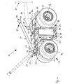
- a generally designated 10 support device is used for Supports a schematically indicated vehicle trailer 11, for example, a trailer or trailer. Of the Trailer 11 is present in particular for a passenger car intended. In principle, it would also be possible a support device according to the invention for supporting a for Truck designed trailer to design.
- the Supporting device 10 has a wheel assembly 12 with steerable Front wheels 13 on a front axle 14 and in this case non-steerable rear wheels 15 on a rear axle 16.
- the wheels 13, 15 are for example solid rubber wheels, with air filled wheels or the like.
- the front axle 14 is in the present case by means of a steering device 17 steerable.
- the axes 14, 16 are suitably continuous axles, but also an independent suspension is possible.
- the rear wheels 15 are e.g. rigid or suspended mounted on a frame 22 of the support device 10.
- the front wheels 13 are rotatable with respect to the frame 22 Bogie 23 arranged.
- the track width of the front wheels 13th is smaller than the track width of the rear wheels 15.
- the bogie 23 is advantageously rotatable by 360 °.
- the trailer 11 can be connected to a coupling device 18 of Support device 10 are coupled.
- the coupling device 18 includes, for example, a coupling head 19 in the Type of ball head, which is oriented upwards.
- the coupling device In this case, 18 stands up in front of the frame 22 ago.
- On the coupling head 19 is a trailer coupling device 20 of the trailer 11 can be placed so that the coupling device 18 and thus the supporting device 10 supports the trailer 11.
- the trailer coupling device 20 is located, for example, on a drawbar 21, which after projecting forward in front of the trailer 11.
- the trailer coupling device 20 is usually used for coupling the Trailer 11 to a towing vehicle, in particular to a passenger car. In the present case, however, it is to the support device 10 coupled.
- the coupling device 18 may be configured differently, for example for coupling truck trailers or like, wherein the coupling means 18, for example may have a kind of coupling jaw.
- the coupling device 18 is located in the support device 10 in an optimal center of gravity, namely in Longitudinal direction 34 of the support device 10 between the two axes 14 and 16.
- charged on the Support device 10 charging trailer 11 preferably the Rear wheels 15. This is caused by the fact that the Clutch device 18 is located near the rear axle 16.
- the steering device is influenced 17 the rotational position of the bogie 23.
- the steering device 17 has a handlebar 24.
- the handlebar 24 acts on the bogie 23.
- the handlebar 24 can from a user located away from the support device 10 become.
- the handlebar 24 is vertically pivotable a pivot bearing 25 of the bogie 23 hinged.
- the Handlebar 24 can be pivoted, for example in a rest position or be folded, in which they on the frame 22 rests. In the upturned state, for example in the position shown in dashed lines, the handlebar serves 24 for steering the support device 10, in particular horizontal steering forces on the bogie 23 transferable are.
- the recordings 27 are for example in the longitudinal direction of the handlebar 24 oriented longitudinal slots. It is also possible, instead of the bearing pin 26 a To provide pivot axis, which has a corresponding passage opening, for example, as the photographs 27 oriented Long hole, passes through the lower end of the handlebar 24.
- a handle 30 for example in the form of a ball head, the of a user of the support device 10 for steering the support device 10 can be taken.
- the transmission 32 is preferably designed so that a relatively high torque on the rear wheels 15th acts.
- a battery assembly 33 supplies the drive 31 with electrical energy.
- the battery assembly 33 is in the longitudinal direction 34 between the front axle 14 and the Rear axle 16 is arranged.
- the battery assembly 33 has present a low center of gravity.
- the battery arrangement 33 is, for example, vertically approximately at height the wheels 13, 15.
- the drive 31 is controllable by control means 35.
- the operating means 35 are located on the steering device 17, expediently in the upper end portion 29 of the handlebar 24.
- Die Operating means 35 include, for example, buttons, operating lever or the like, with which the drive 31 on and off is the direction of rotation and / or the speed of rotation of the drive 31 is adjustable.
- the support device 10 is extremely compact. For example it is about 30 to 40 cm high.
- the distance between the axes 14, 16 is suitably about 35 to 60 cm, with a length of 40 to 50 cm being particularly preferred is. Accordingly, the support 10 can be easily stowed and be taken along, for example in a storage space of the trailer 11.
- the frame 22 is upwardly only slightly before the wheels 13, 15, the embodiment different diameters have, before.
- the height of the frame 22 corresponds to Essentially the diameter of the wheels 13, 15.
- the frame 22nd consists for example of metal and / or plastic.
- the frame 22 for reasons of weight saving also recesses on. Appropriately, is the frame 22 made of aluminum.
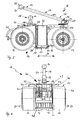
- support surfaces 36 are in the embodiment laterally on Frame 22 and are, for example, by folding elements 37th formed, which protrude sideways in front of the frame 22 sideways.
- the folding elements 37 (it can also rigid bearing surfaces be provided) are about pivot axes 38 between an upwardly pivoted non-use position and a swung down pivoted position of use. In the position of use, the folding elements 37 are located Support struts 39, which like the pivot axes 38 laterally protrude in front of the frame 22.
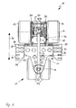
- the coupling device 18 is in the embodiment upwards in front of the frame 22. It is by means of an adjusting device 40 height adjustable.
- the adjusting device 40 includes, for example, electrical and / or hydraulic and / or pneumatic linear drives, spindle drives or like. It is understood that even a manually operated Adjustment device for the coupling device 18 in principle is possible, for example, a hand crank or the like.
- the adjusting device 40 contains vertically oriented, e.g. hydraulic piston actuators 41, on whose upper ends a support plate 42 is arranged, the Coupling head 19 carries.
- the piston drives 41 contain pistons 43, the upward in front of the drive housing 44 of the piston drives 41 project. Depending on a pressurization the piston drives 41 are the piston 43 upwards or down, so that the top of the piston 43 sitting Support plate 42 and thus the coupling head 19 upwards or are movable down.
- the support device 10 may have various types of covers have, for example, the rear and / or the front Cover part of the support device 10.
- the safety can also provide a cover of the wheels be, for example, the driven rear wheels 15. Zur Attachment of such a cover has the support device 20 one or more support points, for example are formed by the frame 22. Additionally is at the supporting device 10 a rearwardly projecting bracket 45th for supporting a cover, not shown in the figure the support device 10 is present. This cover is covered expediently the drive 31 and the gear 33 as well
- a bottom cover 46 at the bottom of the support device 10 protects the drive 31 and the transmission 32 from damage from underneath.
- the support device 10 is not for operation by a Driver thought. Rather, there is an operator of the support device 10 next to this. Accordingly, no seat for a driver present, so that the support device 10th also as a seatless or driverless support device or Shunting device could designate.
- the transmission 32 could be more manoeuvrable.
- a chain drive could be present.
- a chain drive is a combination of steerable wheels with chain driven wheels, e.g. a three-axis arrangement arises.
Abstract
Description
Die Erfindung betrifft eine Stützvorrichtung zum Stützen eines Fahrzeug-Anhängers, insbesondere eines Wohnanhängers, mit einer Radanordnung, auf der der Anhänger zumindest teilweise auflastet.The invention relates to a supporting device for supporting a Vehicle trailer, in particular a trailer, with a wheel assembly on which the trailer at least partially auflastet.
Eine derartige Stützvorrichtung wird beispielsweise durch ein Stützrad gebildet, das an einer Deichsel des Anhängers angeordnet ist. In Fahrstellung des Anhängers ist das Stützrad vom Untergrund weg verstellt, beispielsweise durch Wegschwenken, Hochkurbeln oder dergleichen. Zum Abstellen des Anhängers, aber auch zu Rangierzwecken, wird das Stützrad nach unten verstellt, beispielsweise nach unten verschwenkt, sodass die Deichsel des Anhängers durch das Stützrad gestützt ist. In dieser Stützstellung kann der Anhänger beispielsweise von Hand rangiert werden. Dies ist allerdings unbequem und anstrengend. Auf abschüssigem Gelände ist ein derartiges Rangieren von Hand sogar gefährlich, da der oder die rangierende(n) Person(en) möglicherweise die zum Halten des Anhängers notwendigen Kräfte nicht aufbringen können und vom Anhänger überrollt werden. Such a support device is for example by a Support wheel formed, which is arranged on a drawbar of the trailer is. In driving position of the trailer is the jockey wheel moved away from the ground, for example, by swinging away, Cranks or the like. To turn off the trailer, but also for shunting purposes, the jockey wheel is down adjusted, for example, pivoted down so that the tiller of the trailer is supported by the support wheel. In this support position, the trailer, for example, from Hand ranked. However, this is uncomfortable and exhausting. On sloping terrain is such a maneuvering even dangerous by hand, as the or the ranked Person (s) may be the ones to hold the trailer necessary forces and from the trailer be rolled over.
Andererseits ist das Rangieren des Anhängers mit einem Zugfahrzeug, beispielsweise mit einem Personenkraftwagen, aufgrund beengter Platzverhältnisse oft nicht möglich. Zudem ist ein erhebliches Geschick des Fahrers des Rangier-Zugfahrzeuges gefordert.On the other hand, maneuvering the trailer with a towing vehicle, for example, with a passenger car, due cramped space often not possible. In addition is a considerable skill of the driver of the shunting tractor required.
Es ist daher die Aufgabe der vorliegenden Erfindung, eine Stützvorrichtung der eingangs genannten Art derart weiterzubilden, dass sie ein bequemes Rangieren ermöglicht.It is therefore the object of the present invention to provide a Support device of the type mentioned in such a way, that it allows comfortable maneuvering.
Zur Lösung der Aufgabe weist die Stützvorrichtung der eingangs genannten Art eine Kupplungseinrichtung zum Ankuppeln einer Anhänger-Kupplungseinrichtung des Anhängers auf und enthält einen Antrieb zum Antreiben der Radanordnung.To solve the problem, the support device of the beginning mentioned type a coupling device for coupling a trailer coupling device of the trailer on and includes a drive for driving the wheel assembly.
Die beim Rangieren erforderlichen Antriebskräfte stellt der Antrieb, beispielsweise ein elektrischer oder hydraulischer Antrieb, bereit, sodass ein Nutzer der Stützvorrichtung lediglich Lenkkräfte auf die Stützvorrichtung bzw. den Anhänger ausüben muss. Somit wird das Rangieren erheblich erleichtert. Mit Hilfe der Kupplungseinrichtung kann die Stützvorrichtung an den Anhänger angekuppelt und später wieder abgekuppelt werden. Somit ist die Stützvorrichtung auch für unterschiedliche Anhänger verwendbar, wobei allerdings auf Seiten der Anhänger mit der Kupplungseinrichtung der Stützvorrichtung korrespondierende Anhänger-Kupplungseinrichtungen erforderlich sind. The driving forces required during maneuvering is the Drive, for example, an electric or hydraulic Drive, ready so that a user of the support device only Steering forces on the support device or the trailer must exercise. Thus, maneuvering is greatly facilitated. With the help of the coupling device, the support device coupled to the trailer and later uncoupled again become. Thus, the support device is also for different Trailer usable, although on the part of Trailer with the coupling device of the support device corresponding trailer coupling devices required are.
Besonders bevorzugt ist eine niedrige Bauhöhe der Stützvorrichtung, die dann eine Art Unterflurfahrzeug oder Niederflurfahrzeug bildet. Die Stützvorrichtung weist beispielsweise einen Rahmen auf, dessen Höhe im Wesentlichen der Höhe der Räder der Radanordnung entspricht.Particularly preferred is a low overall height of the supporting device, then a kind of underground vehicle or low-floor vehicle forms. The support device has, for example a frame whose height is substantially equal to the height of Wheels of the wheel assembly corresponds.
Vorteilhafte Ausgestaltungen der Erfindung finden sich in den abhängigen Ansprüchen und der Beschreibung.Advantageous embodiments of the invention can be found in the dependent claims and the description.
Zweckmäßigerweise weist die erfindungsgemäße Stützvorrichtung eine Lenkeinrichtung auf, mit der sie lenkbar ist. Die Lenkeinrichtung ist vorzugsweise von einem Nutzer ergreifbar, der sich abseits der Stützvorrichtung befindet. Die Lenkeinrichtung enthält beispielsweise ein stangenartiges Lenkglied. Die Stellung des stangenartigen Lenkgliedes korrespondiert beispielsweise mit der Stellung gelenkter Räder der Stützvorrichtung. Das stangenartige Lenkglied steht in Abhängigkeit von der jeweiligen Lenkstellung beispielsweise nach vorn oder seitlich vor die Stützvorrichtung vor. Es versteht sich, dass auch andere Lenkhandhaben möglich sind, z.B. ein Lenkrad mit einem zweckmäßigerweise großen Durchmesser, so dass der Außenumfang des Lenkrades seitlich vor die erfindungsgemäße Stützvorrichtung vorsteht. An der Lenkeinrichtung sind zweckmäßigerweise Bedienmittel zur Bedienung des Antriebs vorhanden, beispielsweise Schalter zum Ein- und Ausschalten des Antriebs, zur Vorgabe der Fahrtrichtung und/oder Fahrgeschwindigkeit oder dergleichen. Die Lenkeinrichtung kann einen Servomotor zur Lenkunterstützung aufweisen.Conveniently, the support device according to the invention a steering device with which it is steerable. The steering device is preferably graspable by a user who is located away from the support device. The steering device contains, for example, a rod-like steering member. The Position of the rod-like steering member corresponds for example with the position of steered wheels of the support device. The rod-like steering member is dependent from the respective steering position, for example forward or laterally in front of the support device. It is understood that also other steering handles are possible, e.g. a steering wheel with a suitably large diameter, so that the outer circumference the steering wheel laterally in front of the invention Support device protrudes. At the steering device are expediently Operating means for operating the drive available, for example switches for switching the drive on and off, for specifying the direction of travel and / or driving speed or similar. The steering device can be a servomotor to have steering assistance.
Besonders bevorzugt ist eine zweiachsige Bauweise. Beispielsweise sind an einer Vorderachse ein oder zwei Vorderräder angeordnet und an einer Hinterachse zwei Hinterräder. Die Vorderachse ist vorteilhafterweise lenkbar. Zur Verbesserung der Lenkbarkeit trägt bei, wenn die Spurweite der Vorderräder kleiner ist als die Spurweite der Hinterräder.Particularly preferred is a biaxial construction. For example are arranged on a front axle one or two front wheels and on a rear axle two rear wheels. The front axle is advantageously steerable. To improve the Steerability contributes when the gauge of the front wheels smaller than the track width of the rear wheels.
Die Kupplungseinrichtung ist vorteilhafterweise in Längserstreckungsrichtung der Stützvorrichtung zwischen der Vorder- und der Hinterachse oder im Wesentlichen nahe der Hinterachse angeordnet. Besonders bevorzugt ist eine Anordnung zwischen den beiden Achsen. Jedenfalls bewirken diese Maßnahmen, dass die Stützvorrichtung auch bei auflastendem Anhänger nicht kippt.The coupling device is advantageously in the longitudinal direction the support device between the front and the rear axle or substantially near the rear axle arranged. Particularly preferred is an arrangement between the two axes. In any case, these measures that the support device even with auflastendem trailer does not tip.
Zweckmäßigerweise ist die Kupplungseinrichtung höhenverstellbar, beispielsweise manuell oder motorisch. Die Höhenverstellbarkeit verbessert die Bedienbarkeit der Stützvorrichtung. Beispielsweise wird die Kupplungseinrichtung zunächst in eine untere Stellung verstellt, bevor die Stützvorrichtung so positioniert wird, dass sich die Kupplungseinrichtungen von Anhänger und Stützvorrichtung gegenüberstehen. Sodann wird die Kupplungseinrichtung des Anhängers nach oben verstellt, sodass sie mit der Anhänger-Kupplungseinrichtung in Eingriff gelangt.Conveniently, the coupling device is height-adjustable, for example, manually or by motor. The height adjustment improves the operability of the support device. For example, the coupling device is first adjusted to a lower position before the support device is positioned so that the coupling devices facing the trailer and supporting device. thereupon the coupling device of the trailer is moved upwards, so that they can with the trailer coupling device in Intervention arrived.
Zweckmäßigerweise sind bei der Stützvorrichtung eine oder mehrere Auflageflächen zur Anbringung eines oder mehrerer Gewichte vorhanden. Durch die Gewichte werden die Antriebseigenschaften der Stützvorrichtung verbessert.Conveniently, in the support device one or several bearing surfaces for attaching one or more weights available. The weights are the driving characteristics the support device improved.
Nachfolgend wird ein Ausführungsbeispiel der Erfindung anhand der Zeichnung näher erläutert. Es zeigen:
Figur 1- eine perspektivische Ansicht einer erfindungsgemäßen Stützvorrichtung mit einem schematisch dargestellten angekuppelten Fahrzeug-Anhänger,
Figur 2- die Stützvorrichtung gemäß Fig. 1 von oben, jedoch ohne angekuppelten Anhänger,
- Figur 3
- eine Seitenansicht der Stützvorrichtung gemäß Fig. 2 und
- Figur 4
- eine hintere Ansicht der Stützvorrichtung gemäß
Figuren 2 und 3.
- FIG. 1
- a perspective view of a support device according to the invention with a schematically illustrated coupled vehicle trailer,
- FIG. 2
- the support device according to FIG. 1 from above, but without a coupled trailer,
- FIG. 3
- a side view of the support device of FIG. 2 and
- FIG. 4
- a rear view of the support device according to Figures 2 and 3.
Eine insgesamt mit 10 bezeichnete Stützvorrichtung dient zum
Stützen eines schematisch angedeuteten Fahrzeug-Anhängers 11,
beispielsweise eines Wohnanhängers oder Lastanhängers. Der
Anhänger 11 ist vorliegend insbesondere für einen Personenkraftwagen
vorgesehen. Prinzipiell wäre es aber auch möglich,
eine erfindungsgemäße Stützvorrichtung zum Stützen eines für
Lastfahrzeuge vorgesehenen Anhängers auszugestalten. Die
Stützvorrichtung 10 weist eine Radanordnung 12 mit lenkbaren
Vorderrädern 13 an einer Vorderachse 14 sowie vorliegend
nicht lenkbare Hinterräder 15 an einer Hinterachse 16 auf.
Die Räder 13, 15 sind beispielsweise Vollgummiräder, mit Luft
befüllte Räder oder dergleichen.A generally designated 10 support device is used for
Supports a schematically indicated vehicle trailer 11,
for example, a trailer or trailer. Of the
Trailer 11 is present in particular for a passenger car
intended. In principle, it would also be possible
a support device according to the invention for supporting a for
Truck designed trailer to design. The
Die Vorderachse 14 ist vorliegend mittels einer Lenkeinrichtung
17 lenkbar. Die Achsen 14, 16 sind zweckmäßigerweise
durchgehende Achsen, wobei aber auch eine Einzelradaufhängung
möglich ist. Die Hinterräder 15 sind z.B. starr oder gefedert
an einem Rahmen 22 der Stützvorrichtung 10 gelagert. Die Vorderräder
13 sind an einem bezüglich des Rahmens 22 drehbaren
Drehgestell 23 angeordnet. Die Spurweite der Vorderräder 13
ist kleiner als die Spurweite der Hinterräder 15. Das Drehgestell
23 ist vorteilhafterweise um 360° drehbar.The
Der Anhänger 11 kann an eine Kupplungseinrichtung 18 der
Stützvorrichtung 10 angekuppelt werden. Die Kupplungseinrichtung
18 enthält beispielsweise einen Kupplungskopf 19 in der
Art eines Kugelkopfs, der nach oben orientiert ist. Die Kupplungseinrichtung
18 steht vorliegend nach oben vor den Rahmen
22 vor. Auf dem Kupplungskopf 19 ist eine Anhänger-Kupplungseinrichtung
20 des Anhängers 11 auflegbar, sodass
die Kupplungseinrichtung 18 und somit die Stützvorrichtung 10
den Anhänger 11 stützt. Die Anhänger-Kupplungseinrichtung 20
befindet sich beispielsweise an einer Deichsel 21, die nach
vorn vor den Anhänger 11 vorsteht. Die Anhänger-Kupplungseinrichtung
20 dient üblicherweise zum Ankuppeln des
Anhängers 11 an ein Zugfahrzeug, insbesondere an einen Personenkraftwagen.
Vorliegend ist sie jedoch an die Stützvorrichtung
10 angekuppelt. Es versteht sich, dass die Kupplungseinrichtung
18 auch andersartig ausgestaltet sein kann, beispielsweise
zum Ankuppeln von Lastkraftwagenanhängern oder
dergleichen, wobei die Kupplungseinrichtung 18 zum Beispiel
eine Art Kupplungsmaul aufweisen kann.The trailer 11 can be connected to a
Die Kupplungseinrichtung 18 befindet sich bei der Stützvorrichtung
10 in einer optimalen Schwerpunktlage, nämlich in
Längserstreckungsrichtung 34 der Stützvorrichtung 10 zwischen
den beiden Achsen 14 und 16. Zudem belastet der auf der
Stützvorrichtung 10 auflastende Anhänger 11 vorzugsweise die
Hinterräder 15. Dies wird dadurch bewirkt, dass sich die
Kupplungseinrichtung 18 nahe der Hinterachse 16 befindet.The
Zum Lenken der Stützvorrichtung 10 beeinflusst die Lenkeinrichtung
17 die Drehposition des Drehgestells 23. Die Lenkeinrichtung
17 weist eine Lenkstange 24 auf. Die Lenkstange
24 wirkt auf das Drehgestell 23. Die Lenkstange 24 kann von
einem abseits der Stützvorrichtung 10 befindlichen Nutzer ergriffen
werden. Die Lenkstange 24 ist vertikal schwenkbar an
einem Schwenklager 25 des Drehgestells 23 angelenkt. Die
Lenkstange 24 kann beispielsweise in eine Ruheposition geschwenkt
bzw. geklappt werden, bei der sie auf dem Rahmen 22
aufliegt. Im nach oben geschwenkten Zustand, beispielsweise
in der gestrichelt dargestellten Stellung, dient die Lenkstange
24 zum Lenken der Stützvorrichtung 10, wobei insbesondere
horizontale Lenkkräfte auf das Drehgestell 23 übertragbar
sind.For steering the supporting
Horizontal orientierte Lagerbolzen 26 des Schwenklagers 25
greifen in seitliche Aufnahmen 27 am unteren Ende 28 der
Lenkeinrichtung 17 ein. Die Aufnahmen 27 sind beispielsweise
in Längsrichtung der Lenkstange 24 orientierte Längsschlitze.
Es ist auch möglich, anstelle der Lagerbolzen 26 eine
Schwenkachse vorzusehen, die eine entsprechende Durchgangsöffnung,
beispielsweise ein wie die Aufnahmen 27 orientiertes
Langloch, am unteren Ende der Lenkstange 24 durchgreift.Horizontally oriented bearing
Am oberen Ende 29 der Lenkstange 24 befindet sich eine Handhabe
30, beispielsweise in Gestalt eines Kugelkopfes, die von
einem Nutzer der Stützvorrichtung 10 zum Lenken der Stützvorrichtung
10 ergriffen werden kann.At the
Ein Antrieb 31, beispielsweise ein Elektroantrieb oder ein
Hydraulikantrieb, treibt über ein Getriebe 32 die Hinterräder
15 an. Das Getriebe 32 ist vorzugsweise so ausgelegt, dass
ein verhältnismäßig hohes Drehmoment auf die Hinterräder 15
wirkt. Eine Batterieanordnung 33 versorgt den Antrieb 31 mit
elektrischer Energie. Die Batterieanordnung 33 ist in Längserstreckungsrichtung
34 zwischen der Vorderachse 14 und der
Hinterachse 16 angeordnet. Die Batterieanordnung 33 weist
vorliegend eine tiefe Schwerpunktlage auf. Die Batterieanordnung
33 befindet sich beispielsweise vertikal etwa in Höhe
der Räder 13, 15.A
Der Antrieb 31 ist durch Bedienmittel 35 steuerbar. Die Bedienmittel
35 befinden sich an der Lenkeinrichtung 17, zweckmäßigerweise
im oberen Endbereich 29 der Lenkstange 24. Die
Bedienmittel 35 enthalten beispielsweise Tasten, Bedienhebel
oder dergleichen, mit denen der Antrieb 31 ein- und ausschaltbar
ist, die Drehrichtung und/oder die Drehgeschwindigkeit
des Antriebs 31 einstellbar ist.The
Die Stützvorrichtung 10 baut außerordentlich kompakt. Beispielsweise
ist sie etwa 30 bis 40 cm hoch. Der Abstand zwischen
den Achsen 14, 16 beträgt zweckmäßigerweise etwa 35 bis
60 cm, wobei eine Länge von 40 bis 50 cm besonders bevorzugt
ist. Dementsprechend kann die Stützvorrichtung 10 leicht verstaut
und mitgenommen werden, beispielsweise in einem Stauraum
des Anhängers 11.The
Der Rahmen 22 steht nach oben nur unwesentlich vor die Räder
13, 15, die beim Ausführungsbeispiel unterschiedliche Durchmesser
aufweisen, vor. Die Höhe des Rahmens 22 entspricht im
Wesentlichen dem Durchmesser der Räder 13, 15. Der Rahmen 22
besteht beispielsweise aus Metall und/oder Kunststoff. Beim
Ausführungsbeispiel weist der Rahmen 22 aus Gründen der Gewichtsersparnis
zudem Aussparungen auf. Zweckmäßigerweise ist
der Rahmen 22 aus Aluminium gefertigt.The
Am Rahmen 22 befinden sich Auflageflächen 36, auf die Belastungsgewichte
(nicht dargestellt) aufgelegt werden können, um
die Belastung der angetriebenen Hinterräder 15 zu erhöhen und
somit deren Antriebseigenschaften zu verbessern. Auflageflächen
36 befinden sich beim Ausführungsbeispiel seitlich am
Rahmen 22 und werden beispielsweise durch Klappelemente 37
gebildet, die trittbrettartig seitlich vor den Rahmen 22 vorstehen.
Die Klappelemente 37 (es können auch starre Auflageflächen
vorgesehen sein) sind um Schwenkachsen 38 zwischen
einer nach oben geschwenkten Nicht-Gebrauchsstellung und einer
nach unten geschwenkten Gebrauchsstellung verschwenkbar.
In der Gebrauchsstellung liegen die Klappelemente 37 auf
Stützstreben 39 auf, die wie die Schwenkachsen 38 seitlich
vor den Rahmen 22 vorstehen.On the
Die Kupplungseinrichtung 18 steht beim Ausführungsbeispiel
nach oben vor den Rahmen 22 vor. Sie ist mittels einer Verstelleinrichtung
40 höhenverstellbar. Die Verstelleinrichtung
40 enthält beispielsweise elektrische und/oder hydraulische
und/oder pneumatische Linearantriebe, Spindelantriebe oder
dergleichen. Es versteht sich, dass auch eine manuell bedienbare
Verstelleinrichtung für die Kupplungseinrichtung 18
prinzipiell möglich ist, die beispielsweise eine Handkurbel
oder dergleichen enthält. Die Verstelleinrichtung 40 enthält
vertikal orientierte, z.B. hydraulische Kolbenantriebe 41, an
deren oberen Enden eine Tragplatte 42 angeordnet ist, die den
Kupplungskopf 19 trägt. Die Kolbenantriebe 41 enthalten Kolben
43, die nach oben vor Antriebsgehäuse 44 der Kolbenantriebe
41 vorstehen. In Abhängigkeit von einer Druckbeaufschlagung
der Kolbenantriebe 41 sind die Kolben 43 nach oben
bzw. unten bewegbar, sodass die oben auf den Kolben 43 sitzende
Tragplatte 42 und somit der Kupplungskopf 19 nach oben
oder unten bewegbar sind.The
Die Stützvorrichtung 10 kann verschiedenartige Abdeckungen
aufweisen, die beispielsweise den hinteren und/oder den vorderen
Teil der Stützvorrichtung 10 überdecken. Aus Gründen
der Sicherheit kann auch eine Abdeckung der Räder vorhanden
sein, beispielsweise der angetriebenen Hinterräder 15. Zur
Anbringung einer derartigen Abdeckung weist die Stützvorrichtung
20 eine oder mehrere Stützstellen auf, die beispielsweise
durch den Rahmen 22 gebildet werden. Zusätzlich ist bei
der Stützvorrichtung 10 ein nach hinten vorstehender Bügel 45
zum Stützen einer in der Figur nicht dargestellten Abdeckung
der Stützvorrichtung 10 vorhanden. Diese Abdeckung überdeckt
zweckmäßigerweise den Antrieb 31 und das Getriebe 33 sowie
vorteilhafterweise auch die angetriebenen Hinterräder 15.The
Eine Bodenabdeckung 46 an der Unterseite der Stützvorrichtung
10 schützt den Antrieb 31 bzw. das Getriebe 32 vor Beschädigungen
von unten. A bottom cover 46 at the bottom of the
Die Stützvorrichtung 10 ist nicht für den Betrieb durch einen
Fahrer gedacht. Vielmehr steht ein Bediener der Stützvorrichtung
10 neben dieser. Dementsprechend ist auch kein Sitz für
einen Fahrer vorhanden, sodass man die Stützvorrichtung 10
auch als eine sitzlose oder fahrerlose Stützvorrichtung oder
Rangiervorrichtung bezeichnen könnte.The
Es versteht sich, dass verschiedenartige Varianten der Stützvorrichtung
10 ohne weiteres möglich sind. Beispielsweise
könnte das Getriebe 32 mehrgängig sein.It is understood that various variants of the
Ferner könnte ein Kettenantrieb vorhanden sein. Bei einem derartigen Kettenantrieb ist eine Kombination lenkbarer Räder mit durch Ketten angetriebenen Rädern bevorzugt, wobei z.B. eine dreiachsige Anordnung entsteht.Furthermore, a chain drive could be present. At a Such chain drive is a combination of steerable wheels with chain driven wheels, e.g. a three-axis arrangement arises.
Claims (10)
Priority Applications (1)
| Application Number | Priority Date | Filing Date | Title |
|---|---|---|---|
| EP04000915A EP1555178A1 (en) | 2004-01-16 | 2004-01-16 | Support device |
Applications Claiming Priority (1)
| Application Number | Priority Date | Filing Date | Title |
|---|---|---|---|
| EP04000915A EP1555178A1 (en) | 2004-01-16 | 2004-01-16 | Support device |
Publications (1)
| Publication Number | Publication Date |
|---|---|
| EP1555178A1 true EP1555178A1 (en) | 2005-07-20 |
Family
ID=34610190
Family Applications (1)
| Application Number | Title | Priority Date | Filing Date |
|---|---|---|---|
| EP04000915A Withdrawn EP1555178A1 (en) | 2004-01-16 | 2004-01-16 | Support device |
Country Status (1)
| Country | Link |
|---|---|
| EP (1) | EP1555178A1 (en) |
Cited By (5)
| Publication number | Priority date | Publication date | Assignee | Title |
|---|---|---|---|---|
| WO2008000257A1 (en) * | 2006-07-27 | 2008-01-03 | Mover Technology Aps | A drive unit for trailers and caravans |
| WO2013151417A1 (en) * | 2012-04-05 | 2013-10-10 | Peinemann Equipment B.V. | Trailer, support wheel axle and method for uncoupling and coupling a trailer |
| TWI600557B (en) * | 2013-08-23 | 2017-10-01 | 派尼曼設備公司 | Trailer, support wheel axle and method for uncoupling and coupling a trailer |
| CN108639026A (en) * | 2018-05-07 | 2018-10-12 | 芜湖博创新能源科技有限公司 | A kind of mobile device for new-energy automobile |
| USD989816S1 (en) * | 2021-11-03 | 2023-06-20 | Intradin (Shanghai) Machinery Co., Ltd. | Electric tractor |
Citations (4)
| Publication number | Priority date | Publication date | Assignee | Title |
|---|---|---|---|---|
| US3942823A (en) * | 1974-05-15 | 1976-03-09 | Shields Morton K | Towing tractor construction |
| US4629391A (en) * | 1984-10-09 | 1986-12-16 | Soyk Melvin A | Powered lifter |
| US5139102A (en) * | 1989-07-17 | 1992-08-18 | Dan Pocapalia | Trailer maneuvering dolly |
| US5259471A (en) * | 1992-07-02 | 1993-11-09 | Taylor Robert J | Trailer dolly apparatus |
-
2004
- 2004-01-16 EP EP04000915A patent/EP1555178A1/en not_active Withdrawn
Patent Citations (4)
| Publication number | Priority date | Publication date | Assignee | Title |
|---|---|---|---|---|
| US3942823A (en) * | 1974-05-15 | 1976-03-09 | Shields Morton K | Towing tractor construction |
| US4629391A (en) * | 1984-10-09 | 1986-12-16 | Soyk Melvin A | Powered lifter |
| US5139102A (en) * | 1989-07-17 | 1992-08-18 | Dan Pocapalia | Trailer maneuvering dolly |
| US5259471A (en) * | 1992-07-02 | 1993-11-09 | Taylor Robert J | Trailer dolly apparatus |
Cited By (8)
| Publication number | Priority date | Publication date | Assignee | Title |
|---|---|---|---|---|
| WO2008000257A1 (en) * | 2006-07-27 | 2008-01-03 | Mover Technology Aps | A drive unit for trailers and caravans |
| WO2013151417A1 (en) * | 2012-04-05 | 2013-10-10 | Peinemann Equipment B.V. | Trailer, support wheel axle and method for uncoupling and coupling a trailer |
| RU2602877C2 (en) * | 2012-04-05 | 2016-11-20 | Пейнеманн Эквипмент Б.В. | Trailer, support wheel axle and method for uncoupling and coupling trailer |
| US10259511B2 (en) | 2012-04-05 | 2019-04-16 | Wouter Marcel Sponselee | Trailer, support wheel axle and method for uncoupling and coupling a trailer |
| TWI600557B (en) * | 2013-08-23 | 2017-10-01 | 派尼曼設備公司 | Trailer, support wheel axle and method for uncoupling and coupling a trailer |
| CN108639026A (en) * | 2018-05-07 | 2018-10-12 | 芜湖博创新能源科技有限公司 | A kind of mobile device for new-energy automobile |
| CN108639026B (en) * | 2018-05-07 | 2021-10-15 | 兰州交通大学 | A mobile device for new energy automobile |
| USD989816S1 (en) * | 2021-11-03 | 2023-06-20 | Intradin (Shanghai) Machinery Co., Ltd. | Electric tractor |
Similar Documents
| Publication | Publication Date | Title |
|---|---|---|
| EP2582570B1 (en) | Load and/or transport scooter | |
| EP2870050A1 (en) | Motorised three-wheeled golf trolley | |
| EP3622937B1 (en) | Rollator with an electrical drive | |
| EP1970037A1 (en) | Vehicle for transporting a wheelchair | |
| DE10136369A1 (en) | Small vehicle, especially a wheelchair | |
| DE2844316A1 (en) | TWO-WAY TRACTOR | |
| EP1534574A1 (en) | Cart comprising a motorised drive mechanism | |
| DE102011010727A1 (en) | Towing vehicle for aircraft, which can turn in particular on the spot with just as freely rotatable Bugradaufnahmevorrichtung | |
| EP1555178A1 (en) | Support device | |
| DE2063469B2 (en) | LIFT LOADER WITH SWIVELING DRIVER'S SEAT AND OPERATING UNIT | |
| DE102017205080B4 (en) | Motor vehicle with a mobile vehicle seat and a mobile vehicle seat | |
| EP2623391A2 (en) | Transport device for transporting a golf bag and at least one person | |
| DE202004020831U1 (en) | Support and steering device in particular suitable for separated caravan or trailer normally pulled by car, comprising electric drive unit | |
| DE10031024B4 (en) | Combination transport train for the transport of long or short material | |
| DE102012015651A1 (en) | commercial vehicle | |
| DE620857C (en) | Three or multi-axle chassis, especially for motor vehicles | |
| DE102020000032A1 (en) | Coupling device and mobile walking aid for coupling a self-balancing vehicle | |
| DE602004004389T2 (en) | Vehicle for the disabled | |
| DE102008014641B4 (en) | tractor | |
| WO2005025972A1 (en) | Multi-functional, single-seater, motorised golf cart and golf caddy | |
| DE102006022746A1 (en) | Standing position base for e.g. low-lift forklift truck, has support fixing operating devices on rear and front faces of base in support, respectively, where one device opens and closes coupling device from drivers cab | |
| EP2216232B1 (en) | Motor coach set and corresponding train vehicle | |
| DE19914385C1 (en) | Golf buggy has foldable hitch arm rotatable mounted to fixed hitch link | |
| DE4205327A1 (en) | IC-engined road vehicle with battery-powered trailer - is boosted for additional traction by electric drive to fifth wheel on unit attachable when required | |
| AT405904B (en) | Carriage with a centrally arranged and removable drive unit |
Legal Events
| Date | Code | Title | Description |
|---|---|---|---|
| PUAI | Public reference made under article 153(3) epc to a published international application that has entered the european phase |
Free format text: ORIGINAL CODE: 0009012 |
|
| AK | Designated contracting states |
Kind code of ref document: A1 Designated state(s): AT BE BG CH CY CZ DE DK EE ES FI FR GB GR HU IE IT LI LU MC NL PT RO SE SI SK TR |
|
| AX | Request for extension of the european patent |
Extension state: AL LT LV MK |
|
| AKX | Designation fees paid |
Designated state(s): DE |
|
| STAA | Information on the status of an ep patent application or granted ep patent |
Free format text: STATUS: THE APPLICATION IS DEEMED TO BE WITHDRAWN |
|
| 18D | Application deemed to be withdrawn |
Effective date: 20060221 |