EP1562090A1 - Location based diagnostic method and apparatus - Google Patents
Location based diagnostic method and apparatus Download PDFInfo
- Publication number
- EP1562090A1 EP1562090A1 EP04026329A EP04026329A EP1562090A1 EP 1562090 A1 EP1562090 A1 EP 1562090A1 EP 04026329 A EP04026329 A EP 04026329A EP 04026329 A EP04026329 A EP 04026329A EP 1562090 A1 EP1562090 A1 EP 1562090A1
- Authority
- EP
- European Patent Office
- Prior art keywords
- user
- enterprise
- interesting
- engineer
- sub
- Prior art date
- Legal status (The legal status is an assumption and is not a legal conclusion. Google has not performed a legal analysis and makes no representation as to the accuracy of the status listed.)
- Ceased
Links
Images


Classifications
-
- G—PHYSICS
- G05—CONTROLLING; REGULATING
- G05B—CONTROL OR REGULATING SYSTEMS IN GENERAL; FUNCTIONAL ELEMENTS OF SUCH SYSTEMS; MONITORING OR TESTING ARRANGEMENTS FOR SUCH SYSTEMS OR ELEMENTS
- G05B19/00—Programme-control systems
- G05B19/02—Programme-control systems electric
- G05B19/418—Total factory control, i.e. centrally controlling a plurality of machines, e.g. direct or distributed numerical control [DNC], flexible manufacturing systems [FMS], integrated manufacturing systems [IMS], computer integrated manufacturing [CIM]
- G05B19/4184—Total factory control, i.e. centrally controlling a plurality of machines, e.g. direct or distributed numerical control [DNC], flexible manufacturing systems [FMS], integrated manufacturing systems [IMS], computer integrated manufacturing [CIM] characterised by fault tolerance, reliability of production system
-
- G—PHYSICS
- G05—CONTROLLING; REGULATING
- G05B—CONTROL OR REGULATING SYSTEMS IN GENERAL; FUNCTIONAL ELEMENTS OF SUCH SYSTEMS; MONITORING OR TESTING ARRANGEMENTS FOR SUCH SYSTEMS OR ELEMENTS
- G05B23/00—Testing or monitoring of control systems or parts thereof
-
- G—PHYSICS
- G05—CONTROLLING; REGULATING
- G05B—CONTROL OR REGULATING SYSTEMS IN GENERAL; FUNCTIONAL ELEMENTS OF SUCH SYSTEMS; MONITORING OR TESTING ARRANGEMENTS FOR SUCH SYSTEMS OR ELEMENTS
- G05B23/00—Testing or monitoring of control systems or parts thereof
- G05B23/02—Electric testing or monitoring
- G05B23/0205—Electric testing or monitoring by means of a monitoring system capable of detecting and responding to faults
- G05B23/0259—Electric testing or monitoring by means of a monitoring system capable of detecting and responding to faults characterized by the response to fault detection
- G05B23/0267—Fault communication, e.g. human machine interface [HMI]
- G05B23/027—Alarm generation, e.g. communication protocol; Forms of alarm
-
- G—PHYSICS
- G05—CONTROLLING; REGULATING
- G05B—CONTROL OR REGULATING SYSTEMS IN GENERAL; FUNCTIONAL ELEMENTS OF SUCH SYSTEMS; MONITORING OR TESTING ARRANGEMENTS FOR SUCH SYSTEMS OR ELEMENTS
- G05B2219/00—Program-control systems
- G05B2219/30—Nc systems
- G05B2219/31—From computer integrated manufacturing till monitoring
- G05B2219/31365—Send message to most appropriate operator as function of kind of error
-
- Y—GENERAL TAGGING OF NEW TECHNOLOGICAL DEVELOPMENTS; GENERAL TAGGING OF CROSS-SECTIONAL TECHNOLOGIES SPANNING OVER SEVERAL SECTIONS OF THE IPC; TECHNICAL SUBJECTS COVERED BY FORMER USPC CROSS-REFERENCE ART COLLECTIONS [XRACs] AND DIGESTS
- Y02—TECHNOLOGIES OR APPLICATIONS FOR MITIGATION OR ADAPTATION AGAINST CLIMATE CHANGE
- Y02P—CLIMATE CHANGE MITIGATION TECHNOLOGIES IN THE PRODUCTION OR PROCESSING OF GOODS
- Y02P90/00—Enabling technologies with a potential contribution to greenhouse gas [GHG] emissions mitigation
- Y02P90/02—Total factory control, e.g. smart factories, flexible manufacturing systems [FMS] or integrated manufacturing systems [IMS]
-
- Y—GENERAL TAGGING OF NEW TECHNOLOGICAL DEVELOPMENTS; GENERAL TAGGING OF CROSS-SECTIONAL TECHNOLOGIES SPANNING OVER SEVERAL SECTIONS OF THE IPC; TECHNICAL SUBJECTS COVERED BY FORMER USPC CROSS-REFERENCE ART COLLECTIONS [XRACs] AND DIGESTS
- Y02—TECHNOLOGIES OR APPLICATIONS FOR MITIGATION OR ADAPTATION AGAINST CLIMATE CHANGE
- Y02P—CLIMATE CHANGE MITIGATION TECHNOLOGIES IN THE PRODUCTION OR PROCESSING OF GOODS
- Y02P90/00—Enabling technologies with a potential contribution to greenhouse gas [GHG] emissions mitigation
- Y02P90/80—Management or planning
Definitions
- diagnostic processes have been automated. For example, where a diagnostic process must be performed every week on a resource sub-set, a controller for the resource sub-set may be programmed to automatically perform the process at 5 AM every Monday morning. Similarly, where a process has to be performed every month, the controller may be programmed to automatically perform the process at 5 AM on the first of every month. In these cases either the controller or some other processor is programmed to examine the diagnostic results and, where an interesting condition occurs, to indicate that the interesting condition occurred. In any event, the diagnostic results may be stored for processing via subsequent trend type diagnostic analysis.
- Fig. 2 is a schematic diagram illustrating one of the buildings in Fig. 1 and associated assemblies and other components according to one aspect of the present invention
- Fig. 6 is a flow chart illustrating a simple method according to one aspect of the present invention.
- First building 114 includes a rectilinear facility floor space or area 13 confined by four facility walls collectively identified by numeral 12.
- entire area 13 comprises a single room (i.e., there are no wall partitions within building 114 and all of the building resides on a single level).
- a doorway 16 is provided to allow access to area 13.
- Controller 105 may also run programs designed to facilitate interfacing with facility operators (e.g., maintenance personnel, process engineers, etc.) thereby providing control capabilities and system monitoring capabilities.
- Controller 105 may include its own input and output interfacing devices such as a display screen, a keyboard, a pointing and selecting device such as a mouse or trackball or any other types of interfacing devices known in the art.
- a separate controller 105 is located within each of the facility buildings that is programmed to run building and assembly specific diagnostic processes either routinely or periodically for assemblies that are located within the specific building.
- Proximity requirement column 178 indicates a relative juxtaposition of an employee to the assembly in column 172 that will trigger the processes in column 174 if the time range criteria in column 176 is met.
- processes P12 and P14 may be performed by or on assembly M1.
- processes P9, P10 and P11 may be performed by or on assembly M2.
- "F" indicates a facility so, for instance, F1 indicates the first facility 102 in Fig. 1.
- Qualifications column 180 indicates a specific set of qualifications that an employee must have in order for a triggering relationship to occur. In this regard, it is recognized that not all facility employees will be trained to address all interesting conditions that occur within the facility set 100. Thus, in at least some embodiments of the invention, diagnostic processes will only be triggered when a qualified employee is juxtaposed within the location specified by an associated proximity requirement in column 178.
- different sets of interesting conditions that may occur for a specific assembly are identified by different capital letters (e.g., A, B, C, etc.). Thus, for instance, for assembly M1, the set of potential interesting conditions that may occur is identified as set A. Similarly, for assembly M2, the set of potential interesting conditions that may occur is identified as set B.
- Memory 69 stores the programs performed by processor 71 and also, in at least some embodiments of the invention, stores a WID identifier (e.g., a WID number, a WID user identification number, etc.). It is contemplated that some WIDs 30 may only be configured to provide access information and, in this case, the programs stored in memory 69 may only be access type programs. Where a WID 30 is equipped with control capabilities, control programs are stored in memory 69.
- a WID identifier e.g., a WID number, a WID user identification number, etc.
- Method 182 describes a process whereby diagnostics controller 110 determines whether or not a simple triggering relationship between any of the facility set engineers and a specific automated assembly occurs and, when the triggering relationship occurs, causes diagnostic processes for the specific assembly to be performed. Thereafter, when the results of the diagnostic process are consistent with any interesting condition, the interesting condition is indicated in some fashion.
Abstract
Description
- Not applicable.
- This section of this document is intended to introduce various aspects of art that may be related to various aspects of the present invention described and/or claimed below. This section provides background information to facilitate a better understanding of the various aspects of the present invention. It should be understood that the statements in this section of this document are to be read in this light, and not as admissions of prior art.
- This invention relates generally to diagnostic systems and more specifically to diagnostic systems and methods that perform diagnostic functions at optimal times and that generate diagnostic warnings in an optimal fashion.
- Unless indicated otherwise, in order to simplify this explanation, the present invention will be described hereinafter in the context of the industrial automation industry. Nevertheless, it should be appreciated that the present invention includes various methods and apparatus that may be used in any of several different industries including, but not limited to, industrial automation and building automation as well as the medical field and other businesses where electronic and/or mechanical resource operations are analyzed to determine if tell tale signs of interesting conditions (e.g., a likely failure condition or an unexpected condition) occur.
- Many industries employ complex automated manufacturing systems that include hundreds and even thousands of different electronic and mechanical resources that are integrated into machine lines for performing manufacturing processes. Most electronic and mechanical resources and systems have an expected useful life after which some or all of the components have to be replaced or repaired. In addition, most resources may malfunction prematurely under certain operating conditions or due to imperfections in the resources when the resources themselves were manufactured.
- As with most electronic and mechanical devices, the useful lives of machine line resources can be extended via proper and routine maintenance. To this end, many large manufacturing concerns employ a number of different maintenance engineers charged with routinely maintaining resources. Here, in the case of mechanical resources maintenance may simply include keeping resources well lubricated and periodically replacing worn components. In the case of electronic components and some mechanical components, maintenance may include diagnostically analyzing operating data during normal operation of the resources. For example, for a specific set of resources there may be a range of acceptable operating parameters. A trend over several weeks toward one end or the other of the acceptable range of operating parameters may indicate a likely pending failure of certain components. When a trend is slow, prior experience may indicate that the likely time prior to failure will be relatively long and, when a trend is rapid, experience may indicate that failure is imminent. In some cases diagnostic processes may also include specific operations over and above normal resource operating procedures and analysis of resulting diagnostic data.
- Experience generally guides development of diagnostic processes. For example, in the case of a first resource sub-set, experience may indicate that trend data should be obtained and analyzed on a weekly basis to avoid malfunctions and downtime whereas, in the case of a second resource sub-set, experience may indicate that trend data should be obtained and analyzed on a monthly basis.
- As the number of manufacturing lines within facilities become greater, the number of diagnostic processes required to service facility resources increases. In addition, as the machine lines become more complex, the complexity of diagnostic processes also often increases. Moreover, as diagnostic results are examined, new diagnostic procedures are often developed that take into account new trends in diagnostic results and, in some cases, normal system operating data.
- While diagnostic processes are advantageous and necessary, unfortunately diagnostic requirements increase manufacturing costs appreciably. To this end, large manufacturing concerns often include a large number of different resource types integrated into many different machine lines where the diagnostics required for each of the lines may be unique to the specific machine line. Here, maintenance engineers have to be relatively highly skilled in order to provide services to all lines within a concern's facilities. In addition, in most cases, diagnostic results do not warrant immediate maintenance. Thus, in cases where an engineer has to be present to perform diagnostic processes, if the engineer's presence is not immediately required to address problems related to the diagnostic results, valuable engineer time is wasted.
- Many manufacturing concerns have reduced maintenance engineer or technician training requirements by training specific engineers to service specific machine lines and/or resources. For instance, a large manufacturing concern having twenty manufacturing facilities and many buildings at each facility may employ a total of ten maintenance engineers including two engineers in each of five different maintenance classes. Here each engineer need only be versed in maintaining one fifth of the entire set of resources employed by the concern. A specific engineer may routinely work at a different facility each day of a two week cycle and may be on call to address specific unforeseen interesting conditions in any of the facilities when the conditions occur.
- To reduce the amount of time engineers have to spend performing routine diagnostic processes, in some cases diagnostic processes have been automated. For example, where a diagnostic process must be performed every week on a resource sub-set, a controller for the resource sub-set may be programmed to automatically perform the process at 5 AM every Monday morning. Similarly, where a process has to be performed every month, the controller may be programmed to automatically perform the process at 5 AM on the first of every month. In these cases either the controller or some other processor is programmed to examine the diagnostic results and, where an interesting condition occurs, to indicate that the interesting condition occurred. In any event, the diagnostic results may be stored for processing via subsequent trend type diagnostic analysis.
- Automated diagnostics and multiple classes of maintenance engineers have solved many of the problems associated with maintenance programs. Nevertheless, some shortcomings still exist. For example, where an automatic diagnostic process is performed at 5 AM on the first of every month and a maintenance engineer is in a specific facility on February 27th and is not scheduled to be back in the facility until one week later, if the diagnostic process on March 1 indicates an interesting condition that requires consideration by an engineer, the engineer will have to make an additional and unforeseen trip back to the facility on March 1. In addition to wasting travel time, the additional trip may also throw off the engineer's regular schedule.
- As another example, when an interesting condition is identified, often a signal is sent to a central facility or concern monitoring or service station which then contacts an engineer to resolve the condition. Here, in most cases, a monitoring employee must assess the situation, identify a qualified engineer to address the condition and then issue a work request of some type to the engineer. This process requires that the monitoring employee be familiar with engineer qualifications which is not always the case - especially in the case of large concerns where engineer and monitoring employee turnover may be routine.
- In addition, at any given time there is usually a specific engineer within the sub-set of qualified engineers that is optimal for addressing a specific interesting condition and known systems fail to enable the monitoring employee to identify the optimal engineer. In this regard, all other things being equal, the qualified engineer that is currently least busy should address an occurring interesting condition. Similarly, all other things being equal, the qualified engineer that is currently closest to the location of the interesting condition should address the occurring interesting condition. In addition, all other things being equal, if an interesting condition occurs at a facility location where a qualified engineer is scheduled to be within a short period to perform other maintenance duties, that engineer may be the optimal engineer to address the condition. Known current systems do not enable a monitoring employee to optimally assign tasks to maintenance engineers as a function of various factors such as proximity, qualifications, availability, etc.
- One other problem that has been recognized with existing diagnostic systems is that often there are broad location related trends that cannot be appreciated at the resource level. To this end, where a rash of interesting conditions occurs within a specific area of a facility there may be some environmental cause (e.g., temperature, excess humidity, magnetic field, etc.) that is affecting resource operations. Current known systems have no way of grouping together location based interesting conditions.
- Yet one other problem with addressing diagnostically interesting conditions is related to mobile resources. One recent trend in manufacturing resources is to provide resources that are rapidly reconfigurable so that many different products can be manufactured using different integrated resource subsets or so that one resource may be used at different times with different resource sub-sets. For example, a dryer machine may be wheeled between several facility locations to be used at different times with different plastic molding resource sub-assemblies. Here, where interesting conditions are noticed to service stations, known systems fail to provide a mechanism for determining which of several different stations should receive notice of interesting conditions associated with the mobile resource.
- Certain aspects commensurate in scope with the originally claimed invention are set forth below. It should be understood that these aspects are presented merely to provide the reader with a brief summary of certain forms the invention might take and that these aspects are not intended to limit the scope of the invention. Indeed, the invention may encompass a variety of aspects that may not be set forth below.
- It has been recognized that optimal timing for performing diagnostic processes can be tied to the occurrence of triggering circumstances that periodically occur within a facility. For instance, in at least some cases it has been recognized that it is optimal to perform diagnostics when a facility employee (e.g., a maintenance engineer) is proximate an assembly such that, if an interesting condition occurs, the engineer can address the interesting condition. More specifically, in some cases it is optimal to perform diagnostics only when a maintenance engineer that is qualified to address possible interesting conditions is proximate an assembly and is available (i.e., is not performing other processes for at least some period) to address conditions that may occur. As another instance, where a schedule indicates that an engineer will be proximate an assembly at a specific future time and that the engineer will be available for at least a period, it may be optimal to perform diagnostics at that time and to therefore automatically schedule diagnostic processes for that time. Other optimal triggering circumstances or relationships are contemplated.
- Moreover, it has been recognized that where diagnostic summary processes are periodically performed (e.g., every other Monday morning at 5 A.M.), when an interesting condition occurs, information regarding engineer qualifications (i.e., the types of interesting conditions that the engineer is trained to address), locations, availability, perceived urgency of the condition, etc., can be used to identify and then, in at least some cases, notify an optimal engineer of the condition. In some cases where a condition is not urgent a system may automatically amend the schedule of an engineer to add an interesting condition thereto in an optimal fashion.
- Consistent with the above comments, at least some embodiments of the present invention include method for use with an enterprise operation and at least one processor programmed to perform at least one diagnostic process on the operation and to at least periodically perform at least one summary process on the operation, the method for commencing the at least one summary process and comprising the steps of specifying at least one triggering relationship between at least a first enterprise user and the operation that is to initiate the at least one summary process, determining when the at least one triggering relationship occurs and when the at least one triggering relationship occurs, causing the processor to perform the at least one summary process.
- In at least some embodiments the at least one triggering relationship specifies a first relative juxtaposition of the operation and the first enterprise user. Here, the method may further include the steps of monitoring a period since the last performance of the at least one summary process, performing the at least one summary process at least once every Y hours independent of the occurrence of the at least one triggering relationship and, after the at least one triggering relationship occurs, resetting the period.
- In some cases the method may further include the step of monitoring the period since the last performance of the at least one summary process wherein the at least one triggering relationship specifies that the at least one summary process should be performed when the first user and the assembly are in the first relative juxtaposition and when the period since the last performance of the at least one process exceeds X hours.
- At least some of the inventive methods include a method for use with a component assembly that forms part of an enterprise and at least one processor, the processor programmed to perform at least one diagnostic process on the assembly and to at least periodically perform at least one summary process on the assembly, the method for commencing the at least one summary process and comprising the steps of specifying at least a first relative juxtaposition of the assembly and a qualified enterprise user that is to initiate the at least one summary process wherein the qualified user is any user that is qualified to use the results of the at least first summary process, determining when at least one qualified user is in the at least first relative juxtaposition with respect to the assembly and when at least one qualified user is in the at least first relative juxtaposition with respect to the assembly, causing the processor to perform the at least one summary process.
- Some inventive methods include a method for use with a plurality of devices that are spaced out within a facility, the method for identifying when at least one interesting condition occurs within the facility and comprising the steps of specifying at least a first pattern of diagnostically interesting incidences that correspond to the at least one interesting condition where the at least a first pattern is at least in part related to relative juxtapositions of the diagnostically interesting incidences, performing diagnostic processes related to each of the devices and identifying diagnostically interesting incidences, when a diagnostically interesting incident is identified, identifying the relative juxtapositions of the identified incident with respect to at least a sub-set of previously identified diagnostically interesting incidences, comparing the relative juxtapositions to the at least a first pattern and where the relative juxtapositions match the at least a first pattern, indicating that the first pattern has occurred.
- According to one aspect of the invention some embodiments include a method for use with a component assembly that forms part of an enterprise and at least one processor linked to the assembly, the method for requesting service from a most optimal enterprise user when at least one interesting condition related to the component assembly occurs, the method comprising the steps of monitoring the assembly for at least one diagnostically interesting condition, when at least one diagnostically interesting condition is identified, identifying at least one of the enterprise users as the most optimal user to address the diagnostically interesting condition and indicate the most optimal user.
- According to one other aspect some embodiments of the invention include a method for use with an assembly to be located within an enterprise, the method for associating the assembly with an optimal service resource for reporting diagnostically interesting incidences related to the assembly, the method comprising the steps of positioning at least first and second service resources within the enterprise, positioning the assembly within the enterprise, identifying an optimal one of the at least first and second service resources for monitoring assembly operations based at least in part on the relative juxtaposition of the assembly to each of the first and second service resources, monitoring the assembly for the occurrence of at least one diagnostically interesting incident and when a diagnostically interesting incident occurs, indicating the incident to the optimal one of the first and second service resources.
- These and other objects, advantages and aspects of the invention will become apparent from the following description. In the description, reference is made to the accompanying drawings which form a part hereof, and in which there is shown a preferred embodiment of the invention. Such embodiment does not necessarily represent the full scope of the invention and reference is made therefore, to the claims herein for interpreting the scope of the invention.
- The invention will hereafter be described with reference to the accompanying drawings, wherein like reference numerals denote like elements, and:
- Fig. 1 is a schematic diagram illustrating an enterprise according to one embodiment of the present invention;
- Fig. 2 is a schematic diagram illustrating one of the buildings in Fig. 1 and associated assemblies and other components according to one aspect of the present invention;
- Fig. 3a is a perspective view of an exemplary wireless information device (WID) that may be used to facilitate some inventive methods;
- Fig. 3b is a schematic diagram illustrating various components of the WID of Fig. 3a;
- Fig. 4 is a diagram illustrating an optimal engineer database according to one aspect of the present invention;
- Fig. 5 is a diagram of a diagnostics database according to one aspect of the present invention;
- Fig. 6 is a flow chart illustrating a simple method according to one aspect of the present invention;
- Fig. 7 is similar to Fig. 6, albeit illustrating a more complex method according to the present invention;
- Fig. 8 is another flow chart illustrating yet another method according to the present invention;
- Fig. 9 is a sub-process that may be substituted for a portion of the process illustrated in Fig 8;
- Fig. 10 is a sub-process that, like Fig. 9, may be substituted for the portion of the process illustrated in Fig. 8;
- Fig. 11 is a flow chart of another method according to the present invention;
- Fig. 12 is a flow chart of another method according to the present invention; and
- Fig. 13 is a flow chart illustrating one additional sub-process that may be substituted for a portion of the process illustrated in Fig. 8.
- One or more specific embodiments of the present invention will be described below. It should be appreciated that in the development of any such actual implementation, as in any engineering or design project, numerous implementation-specific decisions must be made to achieve the developers' specific goals, such as compliance with system-related and business related constraints, which may vary from one implementation to another. Moreover, it should be appreciated that such a development effort might be complex and time consuming, but would nevertheless be a routine undertaking of design, fabrication, and manufacture for those of ordinary skill having the benefit of this disclosure.
- Referring now to the drawings wherein like reference numbers correspond to similar elements throughout the several views and, more specifically, referring to Fig. 1, the present invention will be described in the context of an exemplary, albeit simplified, set 100 of
related manufacturing facilities enterprise 100. Each facility includes a number of different buildings. For example, afirst facility 102 includes sixseparate buildings facility 102. Although no detail is shown for the other facilities 116 - 124, here it is assumed that each of the other facilities includes at least one, and in many cases, several separate buildings. In some cases it is contemplated that one or more facilities may not include buildings but, instead, may include outdoor space. - In the present example, the buildings in each facility 102 - 108 each include machines or mechanical and electrical resources that are integrated together to form various automated assemblies or machine lines for performing manufacturing processes. To this end, referring to Fig. 2, a simplified schematic plan view of
exemplary building 114 is illustrated. Here it is assumed that the plan views of each of the other buildings in Fig. 1 would be similar to the view of building 114 in Fig. 2. In the interest of simplifying this explanation only the plan view of thefirst building 114 will be described in detail. - First building 114 includes a rectilinear facility floor space or
area 13 confined by four facility walls collectively identified bynumeral 12. In theexemplary building 114,entire area 13 comprises a single room (i.e., there are no wall partitions within building 114 and all of the building resides on a single level). Adoorway 16 is provided to allow access toarea 13. -
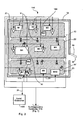
Exemplary building 114 includes ten separate automated assemblies identified by labels M1 through M10. The exemplary automated assemblies M1 through M10 may include any type of manufacturing assembly such as a mill, a drill, a transfer line, a laser cutting device, a vision system, any of several different types of robots, clamps, etc., or any combination of cooperating components. The automated assemblies M1 through M10 are shown as being different sizes to visually illustrate that the automated assemblies may have different physical footprints. For example, assembly M4 is illustrated as having a much larger physical footprint than assembly M8. In general, automated assemblies M1-M10 are spaced out withinarea 13 although, in some cases, automated assemblies may be positioned directly next to each other such as, for instance, assemblies M7 and M8. - It is contemplated that each of automated assemblies M1-M10 includes at least one and, in many cases, a plurality of sensing devices (not illustrated) that sense assembly operating characteristics and provide signals that can be used to facilitate assembly monitoring via an interface (i.e., a WID). For instance, in the case of a drilling assembly, sensors may include limit switches that are tripped when a drill slide reaches various positions along a travel path, on/off switches, speed sensing switches, motor operating characteristic sensors, etc. It is also contemplated that most if not all of assemblies M1-M10 will include a plurality of actuators for causing the assembly components to perform assembly functions.
- In addition to including sensing devices and actuators, it is contemplated that most, if not all, of automated assemblies M1-M10 will include some type of control interface to facilitate control and control adjustment. For example, again, in the case of a drilling assembly, drill slide stroke length may be altered, drill speed may be altered, the angle at which a drill bit enters a work piece may be altered, etc. In Fig. 2 human-machine interfaces are referred to by labels I1 through I8 where HMIs are shown next to assemblies that the HMIs are associated with. For instance,
HMI 11 is associated with assembly M1, HMI I2 is associated with assembly M2, and so on. - In addition to the components described above, building 114 also includes a plurality of communication sensors or access points 11 (only two numbered), a local server/
controller 105, at least one wireless information device (WID) 30, a plurality (two illustrated) ofservice stations controller 105 that form a network. -
Controller 105 may be positioned within building 114 or may be located at some remote location such as, for instance, in a separate building withinfirst facility 102 or at a completely different location such as a remote facility (e.g., 104) associated with building 114 and withinenterprise 100. In Fig. 2,controller 105 is typically linked to at least some components in each of automated assemblies M1-M 10 via two-way data bus 34 that allowscontroller 105 to monitor assembly operating characteristics as well as control assembly operation. For instance, in somecases controller 105 may be linked via anEthernet connection 34 to a proximity sensor that is part of assembly M1 and to an actuator that is part of assembly M3, and so on. -
Controller 105 is a processor based workstation capable of running various types of computer programs. For instance, some programs are assembly control programs that enablecontroller 105 to either separately control each assembly M1-M10 or, safely and precisely, sequence assembly operation thereby allowing relatively complex manufacturing processes to be performed in an efficient manner. In addition, other controller programs may allowcontroller 105 to derive various assembly operating characteristics from monitored or sensed characteristics (e.g., motor voltage and current data is useful to derive stator and rotor resistance estimates, system inductances, identify harmonics, determine system torques, etc.). - Moreover,
controller 105 is programmed to run complex diagnostic processes and algorithms to generate diagnostic data and then to identify operating trends, alarm conditions, potentially hazardous conditions, maintenance requirements, raw material requirements and so on as a function of the diagnostic data. Furthermore,controller 105 may also run programs that facilitate data management and warehousing so that subsequent diagnostic algorithms may be applied to warehoused data to identify historical operating patterns for various purposes. When potentially hazardous conditions occur,controller 105 may be programmed to cause the automated assemblies M1 - M10 to assume non-hazardous operating conditions (e.g., a reduced set of operations or, in some cases, a state in which all mechanical components are parked). -
Controller 105 may also run programs designed to facilitate interfacing with facility operators (e.g., maintenance personnel, process engineers, etc.) thereby providing control capabilities and system monitoring capabilities. To this end,Controller 105 may include its own input and output interfacing devices such as a display screen, a keyboard, a pointing and selecting device such as a mouse or trackball or any other types of interfacing devices known in the art. In the present example it is assumed that aseparate controller 105 is located within each of the facility buildings that is programmed to run building and assembly specific diagnostic processes either routinely or periodically for assemblies that are located within the specific building. - In the present example it is assumed that each of HMIs I1 -I8 also facilitates interfacing with facility operators thereby providing at least some level of control and system monitoring. To this end, HMIs I1 - I8 are linked to
controller 105 viadata bus 34 so that monitored information can be shared therebetween and so that some level of proximate control can be accessed near at least a sub-set of the assemblies. Thus, for instance,controller 105 may monitor all operating characteristics of assembly M1 and may publish data related thereto for access by HMI I1 so that interface I1 needn't separately monitor the same information. Similarly,controller 105 may perform some information analysis and publish the results for use by interface I1. In addition, because HMIs I1 -I8 are linked tocontroller 105 andcontroller 105 controls assemblies M1 - M10, each HMII1-I8 can also be used to control an associated assembly viabus 34 andcontroller 105. While at least some HMIs may be linked directly to associated assemblies M1 - M10 for monitoring and control purposes, hereinafter it will be assumed that each HMI I1 -I8 accesses data and facilitates control viacontroller 105. - Two
service stations controller 105 viadata bus 34. Eachservice station facility buildings 114 through 124. Here, the employee at a station may monitor assembly operations to identify any "interesting conditions" that may occur such as, for instance, malfunctioning assemblies, unexpected operations, depleted raw material levels, etc. - When an interesting condition is identified, it is contemplated that
facility 102 orenterprise 100 will have some specific protocol designed for dealing with the condition. For instance, in some cases the protocol may be for the monitoring employee to notify a maintenance engineer that an interesting condition has occurred. In other cases the protocol may require the monitoring employee to initiate additional diagnostic procedures to generate more information about the interesting condition. Other protocols are contemplated. - Referring still to Fig. 2, each
communication access point 11 includes a two-way wireless transceiver that, as well known in the computer arts, is capable of transmitting and receiving electromagnetic (e.g., radio or infrared) signals within an area proximate the transceiver. Wireless transceivers like access points 11 are well known in the industry and therefore, in the interest of simplifying this explanation, will not be described here in detail. For the purposes of the present invention, it should suffice to say that eachtransceiver 11 transmits information signals which decrease in strength as distance from the transceiver increases. In the illustrated example, sixseparate access points 11 are provided withinarea 13 and are generally equi-spaced withinarea 13. Typically,access points 11 will be mounted on the ceiling within anarea 13 to allow relatively unobstructed communication between anaccess point 11 and other devices that communicate therewith. While access points 11 are illustrated as being substantially equi-spaced withinarea 13, it should be appreciated that other access point arrangements are contemplated and that, in many cases, other access point arrangements may be most suitable given specific assembly layouts, the physical characteristics of each assembly and assembly zone layouts (described below). -
Controller 105 is linked to eachaccess point 11 via two-way data bus 34 that allowscontroller 105 to receive information from the access points 11 and also allowscontroller 105 to provide information to each of the access points 11 for transmission withinarea 13 to WIDs or the like. Information transmitted from eachaccess point 11 tocontroller 105 is typically tagged by the access point so thatcontroller 105 can determine whichaccess point 11 provided the received information. This tagging may either be performed by theaccess point 11 earmarking data packets with an access point identifier (e.g., an access point number) or, in the alternative, may be facilitated by simply providing separate hardwires from each of the access points 11 to thecontroller 105. In a similar fashion,controller 105 andaccess points 11 are configured such thatcontroller 105 can address information to each separate andspecific access point 11. - Referring still to Fig. 2, according to at least one embodiment of the present invention, sub-spaces within
area 13 are earmarked or identified as diagnostic zones or locations associated with different sets of automated assemblies M1-M10 wherein, when a WID 30 (i.e., a person carrying a WID) is within the zone, some diagnostic process may be performed. The exemplary different zones Z1 through Z3 in Fig. 2 are identified by hatched rectilinear blocks. For instance, a space identified by label Z1 includes approximately the upper one third ofspace 13 as illustrated in Fig. 2, a space labeled Z2 including approximately the middle one third ofspace 13 and a space Z3 including approximately the lower one third ofspace 13. In some cases, each of the assemblies that reside within a zone may be diagnostically associated therewith. For instance, in Fig. 2 assemblies M1 M2, M3 may be associated with zone Z1 while assemblies M7, M8, M9 and M10 are associated with zone Z3. - Although not illustrated, in some cases, no diagnostic zones may be specified for one or more of the facility automated assemblies. Moreover, some zones that are associated with specific automated assemblies may not be immediately adjacent the associated automated assemblies but instead may be separated from the associated automated assemblies. Some zones may include all or a part of other zones and, in fact, in some cases, a zone may include an entire building or facility (e.g., 102 in Fig. 1).
- In the example that follows, it will be assumed that assembly M1 is diagnostically associated with zone Z1, assembly M2 is diagnostically associated with entire building 114 (i.e., B1) (see again Fig. 1) and that assembly M3 is diagnostically associated with the entire first facility 102 (i.e., F1).
- Referring again to Figs. 1 and 2,
bus 34 is linked to a single communication network 112 (e.g., an Ethernet, a local area network (LAN), a wide area network (WAN), etc.) and thereby to a remotediagnostic controller 110. As its label implies,diagnostic controller 110 is programmed to manage all diagnostic processes that occur withinenterprise 100. To this end,controller 110 runs one or several algorithms to determine when diagnostic processes should be performed and, when a specific procedure should be performed for a specific assembly,controller 110 transmits commands to thelocal controller 105 associated with the specific assembly thereby causing thelocal controller 105 to perform the process. - In addition, in at least some embodiments of the invention,
diagnostic controller 110 is also programmed to manage maintenance scheduling as a function of results of diagnostic processes. To this end, once diagnostic data has been generated, either one of thelocal controllers 105 or the diagnostic controller may analyze the data to identify any interesting conditions. Where a local controller identifies an interesting condition the local controller publishes the condition vianetwork 112 anddiagnostic controller 110 receives the publication off thenetwork 112. When an interesting condition occurs,controller 110 is, in at least some embodiments, programmed to identify an optimal engineer to address the condition and then notifies the optimal engineer. - Referring still to Fig. 1, in at least some embodiments, a plurality of
access points 11 are also spaced apart throughout each of theseparate facilities network 112. Here, one of the controllers linked tonetwork 112 may be programmed to perform a WID locating process to track WID locations within each of the facilities. For instance, in some cases, one of thelocal controllers 105 may be responsible for tracking WID locations outside the buildings and within thefacilities 102 through 108. In othercases diagnostics controller 110 may be programmed to track WID locations withinenterprise 100 and outside the buildings. - To manage diagnostic processes,
controller 110 is linked to adatabase 111 that, in at least some embodiments, includes foursub-databases numerals Diagnostics database 170 includes information that specifies diagnostic processes that are to be performed for each of the automated assemblies and specific sets of circumstances that trigger when the diagnostic processes are to be performed. Herein, in at least some cases, the triggering sets of circumstances include some specific spatial relationship between a facility employee and a specific automated assembly and therefore, the circumstance sets are generally referred to as triggering relationships. For instance, an exemplary triggering relationship may specify that an associated diagnostic process for assembly M1 should be performed whenever a facility employee enters zone Z1 (see again Fig. 2) or that a process for assembly M2 should be performed whenever a facility employee enters building B1. Many other and more complex triggering relationships are contemplated, a sampling of which are described in greater detail below. - Referring still to Fig. 5,
diagnostics database 170 includes anassembly column 172, adiagnostic processes column 174, atime range column 176, aproximity requirement column 178 and aqualifications column 180.Assembly column 172 lists each of the assemblies or machines M1, M2, M3, etc. that reside withinenterprise 100. - For each assembly in
column 172,diagnostics column 174 lists a set of diagnostic processes associated therewith. For instance, for assembly M1,column 174 lists processes P12 and P14. Here, each of processes P12 and P14 may be very simple or, in some cases may be extremely complex. For instance, process P12 may require an assembly to actually halt normal operations, perform some sequence of mechanical machinations and/or measurements, perform an algorithm on the measurements, analyze the algorithm and, when an interesting condition occurs, report the interesting condition in some fashion. As another instance, diagnostics may be routinely performed by assembly M1 and, process P14 may simply include reporting the results of the diagnostic process in some fashion. Many other diagnostic processes are contemplated. - Referring still to Fig. 5,
time range column 176 specifies a time range that indicates specific time periods during which each of the diagnostic processes incolumn 174 should be performed. In column 176 a "t" indicates the beginning of a timing period and "d" indicates days. The time range for processes P12 and P14 associated with assembly M1 is between 10 and 14 days after the most recent performance of those processes (i.e., 10d<t<14d). Thus, if processes P12 and P14 were performed on May 1, processes P12 and P14 next must be performed on any one of the days between May 11 and May 15 including May 11 and May 15. Similarly, the time range for processes P9, P10 and P11 associated with assembly M2 is between 27 and 33 days after the most recent performance of those processes (i.e., 27d<t<33d). - Referring still to
column 176, while a single time range is specified for each sub-set of processes associated with each of the assemblies incolumn 172, in at least some cases different time ranges will be specified for each of the processes associated with a specific assembly. For instance, a first time range may be specified for process P12 incolumn 174 for assembly M1 while a second and different time range may be specified for process P14 incolumn 174 for assembly M1. -
Proximity requirement column 178 indicates a relative juxtaposition of an employee to the assembly incolumn 172 that will trigger the processes incolumn 174 if the time range criteria incolumn 176 is met. Thus, for instance, referring also to Fig. 2, when an employee is located within zone Z1 during the time range (10d<t<14d - see alsocolumn 176 in Fig. 5), processes P12 and P14 may be performed by or on assembly M1. Similarly, when an employee is located within building B1 during the time range (27d<t<33d -see column 176 in Fig. 5), processes P9, P10 and P11 may be performed by or on assembly M2. Incolumn 178, "F" indicates a facility so, for instance, F1 indicates thefirst facility 102 in Fig. 1. - Referring still to
column 178, while a single proximity requirement is specified for each sub-set of processes associated with each of the assemblies incolumn 172, in at least some cases different proximity requirements will be specified for each of the processes associated with a specific assembly. For instance, a first proximity requirement may be specified for process P12 incolumn 174 for assembly M1 while a second and different proximity requirement may be specified for process P14 incolumn 174 for assembly M1. -
Qualifications column 180 indicates a specific set of qualifications that an employee must have in order for a triggering relationship to occur. In this regard, it is recognized that not all facility employees will be trained to address all interesting conditions that occur within the facility set 100. Thus, in at least some embodiments of the invention, diagnostic processes will only be triggered when a qualified employee is juxtaposed within the location specified by an associated proximity requirement incolumn 178. Incolumn 180 different sets of interesting conditions that may occur for a specific assembly are identified by different capital letters (e.g., A, B, C, etc.). Thus, for instance, for assembly M1, the set of potential interesting conditions that may occur is identified as set A. Similarly, for assembly M2, the set of potential interesting conditions that may occur is identified as set B. Here, set A may include a plurality (e.g., 10, 20, etc.) of separate interesting conditions where one or a sub-set of the interesting conditions may occur at any time. In some cases the interesting conditions may be listed independently indatabase 170 and each may be separately considered when identifying an optimal engineer. - While a simplified diagnostics database is illustrated in Fig. 5, it should be appreciated that other types of diagnostic databases are contemplated, some of which may be even simpler than
database 170 and some of which may be more complex. For example, in at least some cases, it is contemplated that the only qualification for triggering a diagnostic process may be that an employee meets the proximity requirement (column 178) for a specific set of processes. In this case, a simplified version ofdatabase 170 would suffice that does not include the time range andqualifications columns column 178 within the time range specified bycolumn 176 must be "available" to address interesting conditions if they occur. Here, if the employee meeting the other criteria indatabase 170 has a completely booked schedule that cannot be altered, it may make no sense to perform a diagnostic process since, even if an interesting condition occurs, the employee would not be able to address the condition. Here, an additional column may be added todatabase 170 that indicates whether or not availability to address conditions is a factor in determining if processes should be performed. - Referring now to Fig. 4,
optimal engineer database 140 includes information related to specific engineers that are employed byenterprise 100 to address interesting conditions as they occur within theenterprise 100. More specifically, a separate sub-database is provided for each of the employed engineers, three of the sub-databases identified bynumerals -
Sub-database 142 includes two separate sections, aqualifications section 154 and a schedule/location section 156.Qualifications section 154, as the label implies, indicates one or more qualification sets that the specific engineer has that are related to addressing the results of diagnostic processes (e.g., P12, P14, etc.) and, in a fashion similar to that incolumn 180 ofdatabase 170, distinguishes qualification sets by capital letters A, B, etc. Here, as above, the capital letters indicate sets of interesting conditions that the specific engineers have been trained to address. Thus, for instance, the first engineer associated withsub-database 142 is qualified to address each of the interesting conditions in each of sets A and B. Referring also to Fig. 5, because diagnostic processes P12 and P14 require an engineer qualified to address the interesting condition set A, (seecolumn 180 in Fig. 5), the first engineer would be qualified to address the results of processes P12 and P14. However, referring still to Fig. 4, the second engineer associated withsub-database 144 is only qualified to address the interesting conditions in set B and therefore would not be qualified to address the results of processes P12 and P14. - Referring still to Fig. 4, as its label implies, schedule/
location database section 156 includes indicators related to the engineer's weekly schedule. To this end,section 156 includes a table having atime slot column 158 and a series ofday columns Time slot column 158 identifies the different hours of a work day in separate rows. Theexemplary column 158 divides a typical work day by hours from 8 AM to 5 PM. Each of the day columns is assigned to a different day of the work week from Monday through Saturday where the Monday and Tuesday columns are independently identified bynumerals - Within each of the day columns information is inserted for each of the time slots in
column 158. The information in each of the day columns is similar and therefore, unless indicated otherwise, only information incolumn 160 is described here in detail. Referring specifically to the entry incolumn 160 that is aligned with the 5 PM time slot incolumn 158, the exemplary entry includes two types of information. First, the entry includes anindication 164 of whether or not the specific engineer is available at the specific time on the specific day. Here, three separate indicators are used to indicate different levels of availability. A first indicator "F" indicates that the engineer is free or unoccupied during the specific time slot. A second indicator "N" indicates that the engineer is occupied during the time slot and that the engineer's schedule cannot be altered because the tasks assigned during that slot have to be completed during that specific time. A third indicator "O" indicates that the engineer is occupied during that time slot but that the engineer's schedule may be altered during the specific slot because the tasks assigned to the engineer during the specific slot are not time sensitive. In the 5 PM time slot for theMonday column 160 the indicator "O" 164 indicates that the first engineer is occupied but that the engineer's schedule may be altered. - Referring still to Fig. 4, second, the entry in
column 160 for the 5 PM time slot indicates the location at which the engineer is scheduled to be during the specific time slot. In the example thelocation 166 is indicated as L10 which would be a specific location withinenterprise 100. Where an engineer is free during a time slot no location information is provided - here proximity to the most recent location may be assumed in some cases. - As in the case of the
diagnostics database 170, it is contemplated that theoptimal engineer database 140 may take many other forms and may be either more complex or, in some cases, more simple than the form illustrated and described above. - Referring now to Figs. 3a and 3b, a first relatively simple
exemplary WID 30 is illustrated.Exemplary WID 30 includes, generally, a plurality of components that are mounted within a hardened plastic or metallic housing identified bynumeral 32.WID 30 components include aprocessor 71, an input device (e.g., keyboard 36), adisplay screen 34, aspeaker 51 for audio output, atransceiver 38 and amemory 69.Processor 71 is linked to each of the input device,display screen 34,speaker 51,transceiver 38 andmemory 69 for communication therewith.Processor 71 is equipped to run various programs for both displaying information viascreen 34 and for receiving control signals and communicating those control signals to access points 11 (see again Figs. 1 and 2) viatransceiver 38. - The input device may include any of several different types of input components including a typical push-
button keyboard 36,separate selection buttons type selection button 44, and/or selectable icons that may be provided viadisplay screen 34 such as, for instance,icons 45. It is contemplated that, in at least one embodiment, a pointingcursor 46 may be movable aboutscreen 34 and placed over one of the selectable icons (e.g., 45) after which a conventional type mouse clicking action may be used to select one of the icons to cause some display or control function to occur. In other embodiments display 34 may comprise a touch screen where icons are selectable via a stylus or the tip of an operators finger. -
Display screen 34 may be any type of conventional display screen suitable for a handheld device and, for example, may be equipped to display numeric information, icons, graphs such asgraph 47, bar charts, or any other type of monitoring and control information that may be associated with facility machines.Speaker 51 is a conventional small audio output speaker which may be used for any purpose such as providing an audible indication when aWID 30 is removed from a zone, providing operating characteristics in an audible manner, etc. -
Transceiver 38 is mounted proximate the top end ofhousing 32. As in the case of the transceivers that compriseaccess points 11,transceiver 38 is capable of transmitting electromagnetic signals and also receiving such signals so that information can be provided tocontroller 105 or received fromcontroller 105 via access points 11. -
Memory 69 stores the programs performed byprocessor 71 and also, in at least some embodiments of the invention, stores a WID identifier (e.g., a WID number, a WID user identification number, etc.). It is contemplated that someWIDs 30 may only be configured to provide access information and, in this case, the programs stored inmemory 69 may only be access type programs. Where aWID 30 is equipped with control capabilities, control programs are stored inmemory 69. - Hereinafter a number of different methods that are consistent with various aspects of the present invention are described. While all of the methods have some similar characteristics, each is different and each generally has its own level of complexity. In this regard, as indicated above, some of the methods may employ all of the information in the
diagnostic database 170 and theoptimal engineer database 140 and indeed may employ additional information while other methods may only employ a sub-set of the information indatabases simplified databases - Here it should be recognized that, while some
diagnostic controllers 110 in certain systems may be programmed to perform only one of the methods described hereinafter, in other systems, thediagnostic controller 110 may be programmed to perform different methods for different automated assemblies and under differing circumstances. Thus, referring to Figs. 1 and 2, whilediagnostic controller 110 may perform a relatively simple procedure to determine whether or not a diagnostic process should be performed for assembly M1,controller 110 may perform a relatively complex procedure to determine whether or not the diagnostic processes associated with assembly M2 should be commenced and may perform an even more complex process to determine if diagnostics should be performed for assembly M7. - Generally, herein, it is contemplated that the processes hereinafter may be performed in parallel for each of the assemblies (e.g., M1, M2, etc.) within
enterprise 100. To simplify this explanation, unless indicated otherwise, the methods hereinafter will be described in the context of assembly M1 and data indiagnostics database 170 related thereto. Similarly, unless indicated otherwise, the methods will be described in the context of the first engineer associated with sub-database 142 illustrated in Fig. 4. - Moreover, while many different ways for determining the locations of engineers within
enterprise 100 are contemplated, the exemplary invention will be described in the context of a system wherein each engineer is issued a handheld WID 30 (see again Figs. 3a-3b) and where theWIDs 30 andaccess points 11 generate data used by either the local controllers (e.g., 105 in Fig. 2) or bydiagnostics controller 110 in Fig. 1 to determine WID and hence engineer location. Wherecontrollers 105 determine WID locations that information is published via network 34-112 and is obtained bycontroller 110. Referring again to Fig. 2, in the present example, it is contemplated that when aWID 30 is activated within an enterprise building (e.g., 114) or, for that matter, within any of the enterprise facilities 102-108, signals will be transmitted from one of theWIDs 30 and at least a subset of the access points 11 to the other of theWID 30 and the access point subset that are then useable via any of several well known methods to determine the location of the WID within the area in questions (e.g., the facilities, the building, etc.). The location determining method may be based on signal strength or time of flight triangulation or, in some cases, a statistical analysis of received or generated data. - Referring now to Fig. 6, one
simplified method 182 that is consistent with certain aspects of the present invention is illustrated.Method 182 describes a process wherebydiagnostics controller 110 determines whether or not a simple triggering relationship between any of the facility set engineers and a specific automated assembly occurs and, when the triggering relationship occurs, causes diagnostic processes for the specific assembly to be performed. Thereafter, when the results of the diagnostic process are consistent with any interesting condition, the interesting condition is indicated in some fashion. - Referring still to Fig. 6 and to Figs. 1 and 2, at
block 184diagnostic controller 110 determines the locations of all of the engineers withinenterprise 100. Referring also to Fig. 5, the proximity requirement incolumn 178 for resource M1 incolumn 172 is that a WID be located within zone Z1. Therefore, atblock 186,controller 110 determines whether or not aWID 30 is within zone Z1. Where no WIDs are within zone Z1, control passes back up to block 184 where the process described above is repeated. Where at least one WID is located within zone Z1, control passes to block 188 wherecontroller 110 causes the diagnostic processes identified in column 174 (e.g., P12 and P14) be performed. Atblock 190,controller 110 analyzes the results of the diagnostic processes to determine if an interesting condition has occurred. Where no interesting conditions have occurred, control passes back up to block 184. Where an interesting condition has occurred atblock 190, control passes to block 192. Atblock 192,controller 110 indicates that an interesting condition has occurred. Here, blocks 190 and 192 may comprise part of the diagnostic processes. In some cases blocks 190 and 192 and other sub-processes similar thereto will be referred to as summary processes as they summarize the end diagnostic results. - Indication of an interesting condition can take any of several different forms including sending a message to one of the
service stations controller 110 may indicate an interesting condition by automatically transmitting a message to the employee within zone Z1 indicating that an interesting condition has occurred and the specific location at which the interesting condition has occurred along with additional information that may be required by or useful to the dispatched engineers. - Referring now to Fig. 7, a more
complex method 196 is illustrated where the triggering relationship includes several requirements. Specifically, in Fig. 7, the diagnostic controller 110 (see again Fig. 1) triggers diagnostic processes only when an engineer having specific qualifications required to address diagnostic results is in a juxtaposition such that his position meets the proximity requirements for a specific assembly and the engineer meets the proximity requirements within the time range specified incolumn 176 of database 170 (see again Fig. 5) for the specific assembly. Thus, referring once again to Fig. 5 and, more specifically to the row of information corresponding to assembly M1, when an engineer having qualification set A is within zone Z1 within the time range of between ten and fourteen days since the last time the diagnostic processes P12 and P14 were performed for assembly M1, the triggering relationship exists anddiagnostic controller 110 causes diagnostic processes P12 and P14 to again to be performed. - Referring still to Fig. 7 and also to Figs. 1, 2 and 5, at
block 198diagnostic controller 110 tracks the time since diagnostic processes P12 and P14 were last performed for assembly M1 via a time counter. Thus, if diagnostic processes P12 and P14 were last performed for assembly M1 eleven days ago, the time counter indicates a time of eleven days and some hours since the most recent diagnostic process performance. Atblock 200,diagnostic controller 110 compares the time tracked by the time counter with the time range specified incolumn 176 for the specific diagnostic processes. Where the time counter duration is not within the specified time range, control passes back up to block 198 and the process continues to loop. Atblock 200, when the time counter duration is within the time range specified incolumn 176, control passes to block 202. Atblock 202,diagnostic controller 110 determines the locations and identities of the engineers withinenterprise 100. Atblock 204,controller 110 access the proximity requirement information incolumn 178 corresponding to assembly M1. In the present example, the proximity requirement requires that a WID be located within zone Z1. Where no WID is located within zone Z1, control passes back up to block 198. Where at least one WID is located within zone Z1, control passes to block 206. - At
block 206,controller 110accesses column 180 indatabase 170 and determines the qualifications required of an engineer to address the diagnostic results associated with processes P12 and P14 incolumn 174. Next, atblock 206,controller 110 accessoptimal engineer database 140 and, more specifically, the sub-database ofdatabase 140 that corresponds to the engineer whose WID is currently located within zone Z1. Here it will be assumed that the first engineer corresponding to sub-database 142 is the engineer whose WID is located in zone Z1 and therefore,controller 110 accesses sub-database 142. More specifically,controller 110 accesses thequalifications section 154 ofsub-database 142 and, atblock 206, compares the qualifications insection 154 with the qualifications incolumn 180. Where the qualifications insection 154 are different than the qualifications incolumn 180, control passes back up to block 198 where the process described above is repeated. However, atblock 206, where the qualifications insection 154 are identical to the qualifications incolumn 180, control passes to block 208. In the present example, the qualifications incolumn 180 corresponding to assembly M1 include set A and at least one of the sets of qualifications insection 154 for the first engineer also includes set A and therefore, control passes to block 208. - At
block 208,controller 110 accesses the schedule/location section 156 ofsub-database 142 for the first engineer to determine whether or not the first engineer is available to address any interesting conditions that may result from performance of diagnostic processes P12 and P14 at the current time. Here, for example, if the current time is 8:00 a.m., as illustrated incolumn 160 ofsection 156, the first engineer is not available (i.e., an "N" is in column 160). Where the first engineer is not available to address possible interesting conditions, control again passes back up to block 198. However, referring again tocolumn 160 in Fig. 4, if the time is 3:00 P.M. and therefore the first engineer is free to address possible interesting conditions (i.e., an "F" is in column 160), control passes fromblock 208 to block 210 wherecontroller 110 causes diagnostic processes P12 and P14 to be performed. - After
block 210, control passes to block 212 wherecontroller 110 determines whether or not any interesting conditions have occurred. Where no interesting conditions have occurred, control passes to block 216 where the diagnostic process time counter is reset to zero after which control passes back up to block 198 and the process above is repeated. Referring once again to block 212, where an interesting condition does occur, control passes to block 214 where the interesting condition is again indicated after which control passes to block 216. - Once again, indication of the interesting condition can take any of several different forms including transmitting an indication of the interesting condition to the first engineer via the engineer's WID, transmission of some type of indication to a service station or the like, etc.
- Here, it should be appreciated that, in at least some embodiments, where no interesting condition occurs, the entire process described above will be done behind the scenes and the first engineer will have no indication that the process every occurred. However, where an interesting condition does occur and the first engineer is qualified to address the condition and has the time to address the condition, the engineer will be notified of the condition and will be able to address the condition. In some cases, even when no interesting condition occurs, some type of notice may be provided to a proximate and "triggering" engineer via the engineer's WID thereby affirmatively confirming for the engineer that the diagnostic process triggering method is operating properly.
- Referring once again to Fig. 5, it is contemplated that, in some cases, the triggering relationship specified by
database 170 may not occur within the time range specified incolumn 176. In this case, where the diagnostic processes incolumn 174 have to be performed periodically and, at least once within the longest duration specified by the time range, in at least some cases, if the longest duration specified by the time range occurs prior to the triggering relationship occurring,diagnostic controller 110 will automatically cause the diagnostic processes incolumn 174 to be performed. Thus, for instance, referring once again to the row of information correspond to assembly M1 incolumn 172, if the triggering relationship specified bycolumns controller 110 automatically performs processes P12 and P14. In this case, if at least one interesting condition is identified after processes P12 and P14 have been performed,controller 110 may perform some type of indicating process. - Referring now to Fig. 8, a
method 230 consistent with the comments above and that may run either separately or in parallel with one of the methods described above is illustrated.Method 230, is a method for, when a diagnostic process is performed and at least one interesting condition is identified, providing notification to an optimal enterprise engineer so that the interesting condition can be optimally addressed. To this end, referring also to Figs. 1 and 2, atprocess block 232,controller 110 tracks the time since the last diagnostic process was performed, again using the time counter described above. Atblock 234,controller 110 determines whether or not the time limit specified by the time range incolumn 176 has occurred. Prior to the time limit occurring, control passes back up to block 232. After the time limit is reached, control passes to block 236. In the present example, with respect to assembly M1, the maximum limit of the time range specified incolumn 176 is fourteen days. Therefore, after fourteen days since the most recent performance of diagnostic processes P12 and P14, control passes to block 236. Atblock 236,controller 110 performs the diagnostic processes P12 and P14. Atblock 238,controller 110 determines whether or not any interesting conditions have been identified in the diagnostic processes results. Where no interesting conditions have occurred, control passes to block 246 where the time counter is reset to zero and restarted. - Referring once again to block 238, where an interesting condition does occur, control passes to block 240 where
controller 110 identifies the optimal engineer to address the interesting condition. Atblock 242,controller 110 notifies the optimal engineer that the interesting condition has occurred after which control passes to block 246 and the time counter is again set to zero and restarted. Afterblock 246, control passes again to block 232 where the time counter duration is again monitored. - Many different sub-processes for identifying the optimal engineer to address identified interesting conditions are contemplated, some of which are very complex and others of which are relatively simple. Referring now to Fig. 9, one exemplary sub-process that may be used to replace process block 240 in Fig. 8 is illustrated. Referring also to Fig. 8, after an interesting condition occurs at
block 238, according to the sub-process of Fig. 9, control passes to block 250 wherecontroller 110 identifies the qualification requirement set corresponding to the expired time range incolumn 176. In the present example, qualification set A corresponds to the expired time range associated with assembly M1. Afterblock 250, control passes to block 252. - At
block 252controller 110 identifies the next closest engineer as a current engineer. In this case, for example, referring again to Fig. 2, where only two engineers using WIDs are located withinspace 13 and the first engineer is proximate assembly M4 (seeWID 30 in Fig. 2) while the second engineer is proximate assembly M10 (see WID 30' in Fig. 2),controller 110 identifies the first engineer as the current engineer because the first engineer is the closest engineer to assembly M1. Continuing, atblock 254,controller 110 determines whether or not the current engineer is qualified. In this regard,controller 110 accesses the sub-database corresponding to the current engineer and specifically the qualifications section of that sub-database and compares the qualifications of the current engineer to the qualifications fromcolumn 180. Where the current engineer is not qualified to address the interesting conditions for the specific assembly, control passes back up to block 252 andcontroller 110 identifies the next closest engineer as the current engineer. In the example above, where the first engineer is proximate assembly M4 and a second engineer is proximate assembly M10 in Fig. 2, if the first engineer is not qualified atblock 254, the next time throughblock 252controller 110 selects the second engineer proximate assembly M10 (i.e., the engineer associated with WID 30) as the current engineer and control loops back down to block 254. In the present example it will be assumed that the first engineer is qualified as consistent with the example above and therefore control passes to block 256. - Referring still to Figs. 1, 2 , 4, 5 and 9, at
block 256,controller 110 determines whether or not the current engineer is available to address the interesting condition by accessing theoptimal engineer database 140 and, more specifically schedule/location section 156 thereof. Where the current engineer is not available, control again loops back up to block 252 wherecontroller 110 again identifies the next closest engineer as the current engineer and the process described above is repeated. Eventually, atblock 256, one of the engineers will be identified as current and available and at that point, control will drop to block 258. - At
block 258, the current engineer is set equal to the optimal engineer. Afterblock 258 control passes back to block 242 in Fig. 8 where the optimal engineer is notified of the interesting condition so that the engineer can address the condition. - In some cases, an interesting condition may not be urgent and, in these cases, it may be preferable to wait until an available qualified engineer is scheduled to be within the general location in which the interesting condition occurs so that existing schedules for engineers do not have to be altered more than necessary. To this end, Fig. 10 illustrates a sub-process 240 that may be used to replace a portion of the process of Fig. 8 described above wherein, when an interesting condition occurs, when the interesting condition is urgent, the closest qualified and available engineer is notified of the condition and, when an interesting condition is not urgent, the next qualified engineer that is available and that will next meet the proximity requirement is notified via an amendment to the engineer's schedule to add an interesting condition thereto to be addressed.
- Referring to Figs. 1, 2, 4, 5, 8 and 10, after an interesting condition has been identified at
block 238 in Fig. 8 control passes to block 260 in Fig. 10. Atblock 260,controller 110 accesses database 170 (see again Fig. 5) and identifies the qualification set of an engineer that is qualified to address the interesting conditions as specified incolumn 180. Afterblock 160, control passes to block 262 wherecontroller 100 determine whether or not the interesting condition is urgent. Here, although not illustrated above,diagnostic database 170 may include another column that indicates specific instances of interesting conditions and whether or not those conditions are deemed to be urgent or not urgent. In this case,controller 110 uses the information in the additional column to determine whether or not a condition is urgent. Where a condition is urgent atdecision block 262, control passes to block 268.Blocks blocks loop including blocks block 274 control passes back to block 242 in Fig. 8 where the optimal engineer is notified as described above. - Referring still to Fig. 10, and, once again to block 262, when an interesting condition that was previously identified is not considered urgent, control passes to block 264. At
block 264controller 110 identifies the next qualified and available engineer that will meet the proximity requirement as the optimal engineer. To this end, atblock 264controller 110 accesses database 140 (see again Fig. 4) and searches the location information in the day columns for each of the engineers that is qualified to address the interesting condition that occurred. Once a location in an existing schedule that is proximate the assembly at which the interesting condition occurred is identified,controller 110 amends the optimal engineer's schedule to add the interesting condition atblock 266. For example, referring to Figs. 2 and 4, where an interesting condition corresponding assembly M1 occurs at 1:00 P.M. on Monday afternoon and location L9 is proximate assembly M1,controller 110 may amend the schedule associated with the first engineer to add the interesting condition to the engineer's schedule for the 3:00 P.M. time slot (seecolumn 160 wherein the "F" indicator in the 3:00 P.M. time slot indicates that the first engineer is free at that time). Afterblock 266, in the illustrated method, control passes back to block 242 in Fig. 8 where the optimal engineer is notified that his schedule has been amended. This notification may indicate the time and date affected as well as the nature of the interesting condition, the assembly associated with the interesting condition, the location of the interesting condition, and so on. - Referring once again to Fig. 1, according to an additional aspect of the present invention,
diagnostic controller 110 may be programmed to analyze patterns of diagnostic problems or interesting conditions that occur and, based on those patterns, to indicate when specific potentially problematic patterns are identified. For example, in Fig. 1 where a large number of interesting conditions occur in a small area withinfacility 102 such as, for example, in the first andsecond buildings facilities number 4, that pattern may be a sign that something is wrong in buildingnumber 4. - While problematic patterns are described above in the context of a facility-wide system, it should be appreciated that similar problematic or potentially problematic patterns may be specified for sub-spaces within each or any one or a sub-set of the buildings within a facility. For example, referring also to Fig. 2, within building 114, one problematic pattern to be monitored by a
diagnostic controller 110 may be whenever ten or more interesting conditions occur within 30 feet of any location withinspace 13. Many other problematic interesting condition patterns are contemplated by the present invention. - Referring now to Fig. 11, one
method 300 for identifying problematic interesting condition patterns is illustrated. Referring also to Figs. 1 and 2, atblock 302, problematic patterns are defined that correspond to separate buildings (e.g., 114), facilities and, in some cases within the entire enterprise. The problematic patterns may be stored indatabase 350 as illustrated in Fig. 1. Afterblock 302, control passes to block 304 where, during normal system operation,diagnostic controller 110 monitors for interesting conditions in any of the manners described above. Atblock 306, where no interesting condition occurs, control loops back up to block 304 where monitoring continues. Atblock 306 when an interesting condition occurs, control passes down to block 308 where the interesting condition that has recently occurred is added to an interesting condition map which may also be stored in database 111 (although not illustrated in Fig. 1). Afterblock 308, atblock 310,controller 110 compare the interesting condition map or, sections thereof, to the defined problematic patterns (i.e., the patterns that were defined at block 302). Where the interesting condition map or sections thereof do not match one of the defined patterns, control again loops back up to block 304 where the process as described above is repeated. Atblock 310, however, when the map or section thereof does match one of the defined patterns, control passes to block 312 where the defined pattern that has occurred is indicated in some manner. Here as in many of the methods as described above, indication of the occurrence of a defined pattern may include transmitting some type of a warning to a service station or, in some cases, to a qualified and available engineer within the general vicinity in which the pattern has occurred. - According to yet one other aspect of the present invention, in some cases it is contemplated that one or more of the assemblies within one of the buildings that comprise a facility may be mobile. For example, referring once again to Fig. 2, it may be that assembly M10 is mobile and therefore may be movable within building 114 or, through
doorway 16 out of building 114 and to any other location within the first facility 102 (see again Fig. 1). In this case, while assembly M10 may have various diagnostic procedures associated therewith, the association between assembly M10 and the service stations (i.e., 169 and 171 in Fig. 2) will be altered such that the optimal service station for receiving indications of interesting conditions with respect to assembly M10 may be altered. To this end, the present invention contemplates at least one method whereby, when assembly M10 is moved within a facility or, in deed within anentire enterprise 100, association between assembly M10 and the service stations may be altered to ensure optimal association under all circumstances. To this end, onemethod 320 for modifying assembly/service station association as a function of location is illustrated in Fig. 12. - Referring to Fig. 12 and also again to Figs. 1 and 2, at block 322 a rule set for selecting service stations that at least in part is based upon juxtaposition of mobile assemblies is specified. The rule set 360 may be stored in
database 111 as illustrated in Fig. 1. Atblock 324, after an assembly M10 has been moved to a location at which assembly M10 will operate,controller 110 determines the location of the assembly. Next, atblock 326,controller 110 applies the rule set to identify which station assembly M10 should be associated with for diagnostic purposes. Referring specifically to Fig. 2, where the rule set indicates that mobile assemblies should be associated with the closest service stations within the building in which the mobile assemblies are located, with assembly M10 located as illustrated, the service station selected is thesecond service station 171. Continuing, atblock 328,controller 110 forms an association or, where assembly M10 has already been associated previously with another service station, a reassociation of assembly M10 with the optimal service station based on the current location of assembly M10. Thereafter, whenever a diagnostically interesting condition occurs at assembly M10, notice thereof is sent tosecond station 171. - While the invention may be susceptible to various modifications and alternative forms, specific embodiments have been shown by way of example in the drawings and have been described in detail herein. However, it should be understood that the invention is not intended to be limited to the particular forms disclosed. For example, while a WID and
access points 11 are used to determine location of engineers in the exemplary system described above, it should be appreciated that other location determining systems are contemplated. For instance, when an engineer enters afacility 102 or a specific building (e.g., 114) within a facility, the engineer may be required to use a card key to gain access. Thus, general location may be determinable via most recent key access. Similarly, when an engineer addresses an interesting condition or otherwise interfaces with an assembly, the engineer may have to log onto one of the HMIs (e.g., I1-I8) and therefore HMI location may be used to determine engineer location. - In addition, in some cases a diagnostic process may require excessive time to perform such as, for instance, an entire hour. In these
cases controller 110 may be programmed to analyze schedules of qualified engineers in advance to determine when an engineer will be within the general vicinity of an assembly within a specified time range and will have at least some time to address possible interesting conditions. If a time and engineer are identified,controller 110 may start the diagnostic process in advance (e.g., 1.5 hours) of the time when the engineer will be proximate and available so that any interesting conditions that occur can be addressed in a manner consistent with the engineer's schedule. Here, another factor in determining if the process should be started in advance may be a determination in advance that the engineer is on schedule. For instance, in the example above where a diagnostic process requires an hour,controller 110 may determine that an engineer that is identified to address possible interesting conditions at a first assembly is located at a location consistent with the engineers schedule one hour prior to the time at which the engineer is free to address first assembly conditions. Here, in at least somecases controller 110 may not commence the diagnostics processes for the first assembly if the engineer is off schedule. - In addition, another factor when determining whether or not diagnostic processes should commence may be current status of an assembly. For instance, where a diagnostic process requires that a machine's normal operating schedule be interrupted, it may not be optimal to alter normal operations due to resulting downtime. Here, the pre-scheduling concepts described above are particularly important.
- Furthermore, it is contemplated that any facility engineer may desire to receive specific interesting condition notices associated with specific assemblies independent of whether or not the engineer is the optimal engineer at a subsequent time. For instance, if one engineer has dealt with a specific interesting condition often in the past it may be suitable for that engineer to address the condition when it occurs again or to at least be consulted regarding the next occurrence. Here, to support this concept, an exceptions field (e.g., one labeled 370 in Fig. 4) may be provided in each of the engineer sub-databases (e.g., 142 in Fig. 4) that stores data indicating exceptions selected via the specific engineer. In Fig. 4 exemplary exceptions are indicated via assembly indicators although more specific and separate interesting condition indicators are contemplated.
- In addition, while the examples above assume generally that diagnostic processes are commenced after triggering relationships occur or after a time period has expired, it is also contemplated that diagnostic processes and data gathering may be continual and that triggering relationships simply kick off summary processes or the final steps in the diagnostic processes. For instance, in some cases a triggering relationship may simply call for transmission of summary diagnostic results or current results. In other cases a triggering relationship may commence performance of an algorithm on historically collected and archived data to identify interesting conditions and then notice thereof.
- Moreover, while specific orders of process steps are described above, it should be understood that in many cases the order of steps may be altered. For example, in Fig. 7, the order of decision blocks 206 and 208 may be switched. Other step orders are contemplated.
- Furthermore, in some cases it may be that when an interesting condition occurs and notice is provided to a specific optimal engineer, affirmative acceptance of the task of addressing the condition has to be indicated by the engineer within a given accept period or else a next most optimal engineer will be identified and given notice. To this end, a sub-process 378 that may be substituted for
blocks 238 through 246 in Fig. 8 is illustrated in Fig. 13. - Referring also to Figs. 1, 2 and 8, after a diagnostic process has been performed at
block 236, control passes to block 380 in Fig. 13. Atblock 380,controller 110 determines whether or not an interesting condition has been identified. Where no interesting condition has been identified, control passes to block 392 where the diagnostic timer is reset and, also, a second timer, referred to herein as an acceptance timer, is also reset. The acceptance timer, as described hereinafter, is a timer that tracks the time since an optimal engineer has been notified of the occurrence of an interesting condition. - Referring again to block 380, where an interesting condition has been identified, control passes to block 382. At
block 382,controller 110 identifies the next optimal engineer based on whatever criteria have been specified for making that identification. Atblock 384 the optimal engineer is notified of the interesting condition and, as part of the notification, a query is provided to the optimal engineer requesting that the optimal engineer affirmatively accept responsibility for addressing the condition. Here, the task request may comprise presentation of a request to the engineer via the engineer'sWID 30 along with selectable accept and reject icons provided ondisplay 34. - Continuing, at
block 386 the acceptance timer is turned on. Atblock 388,controller 110 determines whether or not an indication has been received from the optimal engineer that the optimal engineer has accepted the task. Where the task is accepted, control passes to block 392 where, again, the diagnostic and acceptance timers are both reset. Atblock 388, where the task has not been accepted, control passes to block 390. Atblock 390,controller 110 determines whether or not the accept period has expired. Where the accept period has not expired, control passes back up to block 388 where the loop described above is repeated. Where the accept period has expired atblock 390, control loops back up to block 382 where a next optimal engineer is identified and the process above continues. Once the diagnostic and acceptance timers have been reset atblock 392, control passes back to block 232 in Fig. 8. - In the claims that follow the term "operation" is sometimes used to refer to an enterprise process where one type of enterprise process may be an operating assembly. Other enterprise processes may include monitoring of process temperatures, pressures, volumes and so on. Thus, the term "operation is used to express a broader concept than a simple mechanical and/or electronic assembly.
- Thus, the invention is to cover all modifications, equivalents, and alternatives falling within the spirit and scope of the invention as defined by the following appended claims.
- To apprise the public of the scope of this invention, the following claims are made:
- In summary, a method and apparatus for use with a component assembly are disclosed that forms part of an enterprise and at least one processor, the processor programmed to perform at least one diagnostic process on the assembly and to at least periodically perform at least one summary process on the assembly, the method for commencing the at least one summary process and comprising the steps of specifying at least one triggering relationship between at least a first enterprise user and the assembly that is to initiate the at least one summary process, determining when the at least one triggering relationship occurs and, when the at least one triggering relationship occurs, causing the processor to perform the at least one summary process.
Claims (52)
- A method for use with an enterprise operation and at least one processor programmed to perform at least one diagnostic process on the operation and to at least periodically perform at least one summary process on the operation, the method for commencing the at least one summary process and comprising the steps of:specifying at least one triggering relationship between at least a first enterprise user and the operation that is to initiate the at least one summary process;determining when the at least one triggering relationship occurs; andwhen the at least one triggering relationship occurs, causing the processor to perform the at least one summary process.
- The method of claim 1 wherein the at least one summary process includes analyzing the results of the at least one diagnostic process.
- The method of claim 2 wherein the at least one summary process also includes, when the analyzing step results in at least one interesting condition, performing another process.
- The method of claim 1 wherein the at least one summary process includes indicating at least a sub-set of the results of the at least one diagnostic process.
- The method of claim 4 wherein the step of indicating includes providing an interface to at least the first user and indicating the at least a sub-set of results to the first user via the interface.
- The method of any preceding claim wherein the triggering, relationship also initiates the at least one diagnostic process.
- The method of 6 wherein the at least one summary process includes the steps of analyzing the results of the at least one diagnostic process to identify interesting conditions.
- The method of 7 further including the step of, wherein when an interesting condition is identified, indicating that an interesting condition has occurred.
- The method of claim 1 wherein the at least one triggering relationship specifies a first relative juxtaposition of the operation and the first enterprise user.
- The method of claim 9 further including the steps of monitoring a period since the last performance of the at least one summary process, performing the at least one summary process at least once every Y hours independent of the occurrence of the at least one triggering relationship and, after the at least one triggering relationship occurs, resetting the period.
- The method of any preceding claim wherein the step of determining includes providing an information device to the at least a first user and at least one sensor for sensing location of the information device and determining location of the information device via interaction between the information device and the at least one sensor.
- The method of claim 11 wherein the step of providing an information device and at least one sensor includes providing a wireless information device (WID) and at least one access point and wherein the step of determining location includes transmitting signals from at least one of the WID and the access point to the other of the WID and the access point and using the transmitted signals to determine location.
- The method of claim 12 further including the steps of, when the at least one summary process identifies an interesting condition, performing a function.
- The method of claim 13 wherein the step of performing a function includes indicating the interesting condition to the at least one user via the WID.
- The method of claim 9 wherein a plurality of users use the enterprise, the step of determining including determining if at least one of the enterprise users is in the specified relative juxtaposition to the assembly and, where at least one of the users is in the specified relative juxtaposition, determining if the user in the specified juxtaposition is the first user and, where the user in the specified juxtaposition is the first user, determining that the triggering relationship has occurred.
- The method of claim 9 wherein a plurality of users use the enterprise and wherein the at least one triggering relationship includes relationships with at least a sub-set of the enterprise users where each sub-set user is characterized by a triggering characteristic set, the step of determining including determining if at least one of the enterprise users is in the specified relative juxtaposition to the assembly and, where at least one of the users is in the specified relative juxtaposition, determining if the user in the specified juxtaposition is characterized by the triggering characteristic set.
- The method of claim 16 wherein the triggering characteristic set includes qualification to use at least one summary process results.
- The method of claim 17 wherein the triggering characteristic set includes availability to examine summary process results and wherein the step of determining further includes accessing a schedule database that indicates the schedules of the enterprise users and determining if the user in the specified relative juxtaposition is currently unoccupied.
- A method for use with an enterprise operation and at least one processor linked to the operation, the method for requesting service from a most optimal enterprise user when at least one interesting condition related to the operation occurs, the method comprising the steps of:monitoring the operation for at least one diagnostically interesting condition;when at least one diagnostically interesting condition is identified, identifying at least one of the enterprise users as the most optimal user to address the diagnostically interesting condition; andindicating the most optimal user.
- The method of claim 19 wherein the step of identifying includes identifying the enterprise user that is most proximate the operation.
- The method of claim 20 wherein the step of identifying the most proximate user includes providing a wireless information device to each enterprise user, determining the juxtapositions with respect to the operation of at least a sub-set of the WIDs and comparing the relative juxtapositions.
- The method of claim 21 further including the step of providing at least one stationary access point within the enterprise, the step of determining the relative juxtaposition of each of the sub-set of WIDs including transmitting signals from one of the WID and the at least one access point to the other of the WID and the at least one access point, using the transmitted signals to determine the location of the WID with respect to the operation and comparing the WID locations.
- The method of claim 21 wherein the step of identifying includes identifying a sub-set of the users that is qualified to address the diagnostically interesting condition and selecting one of the qualified users as the most optimal user.
- The method of claim 19 wherein the step of identifying includes accessing a schedule database that indicates the schedules of the enterprise users.
- The method of claim 24 wherein the step of identifying further includes identifying a sub-set of the enterprise users that is currently unoccupied and selecting one of the unoccupied users as the most optimal user.
- The method of claim 24 wherein the enterprise includes sub-spaces and the operation is within a first sub-space and wherein the step of identifying further includes identifying the one of the enterprise users that is next scheduled to be within the first sub-space.
- The method of claim 26 further including the step of amending the schedule of the user that is next scheduled to be within the first sub-space to include an appointment to address the interesting condition.
- The method of claim 19 further including the step of providing notice to the optimal user that the at least one interesting condition has occurred.
- The method of claim 28 wherein the step of providing notice includes amending a schedule for the optimal user to add an appointment to address the interesting condition.
- The method of claim 29 wherein the step of amending a schedule includes requesting acceptance of the appointment from the optimal user and, when the appointment is accepted, amending the schedule.
- The method of claim 30 wherein the step of requesting acceptance includes starting a timer after requesting acceptance and, after a query period expires, identifying the next most optimal user to address the interesting condition and indicating the next most optimal user.
- The method of claim 30 wherein, when the appointment is rejected, the method further includes the step of identifying the next most optimal user to address the interesting condition and indicating the next most optimal user.
- The method of claim 19 wherein the step of identifying includes identifying the enterprise user that most recently addressed the interesting condition for the specific assembly.
- The method of any preceding claim wherein the operation includes an automated assembly.
- An apparatus for use with an enterprise operation and at least one processor programmed to perform at least one diagnostic process on the operation and to at least periodically perform at least one summary process on the operation, the method for commencing the at least one summary process, the apparatus comprising:a database specifying at least one triggering relationship between at least a first enterprise user and the operation that is to initiate the at least one summary process; anda processor programmed to perform the steps of:determining when the at least one triggering relationship occurs; andwhen the at least one triggering relationship occurs, performing the at least one summary process.
- The apparatus of claim 35 wherein the at least one diagnostic process is performed routinely and wherein the processor performs the at least one summary process by analyzing the results of the at least one diagnostic process.
- The apparatus of claim 35 wherein the processor performs the at least one summary process by indicating at least a sub-set of the results of the at least one diagnostic process.
- The apparatus of claim 37 wherein the processor indicates by providing an interface to at least the first user and indicating the at least a sub-set of results to the first user via the interface.
- The apparatus of claim 35 wherein the processor also initiates the at least one diagnostic process when the triggering relationship occurs.
- The apparatus of claim 35 wherein the at least one triggering relationship specifies a first relative juxtaposition of the operation and the first enterprise user.
- The apparatus of claim 40 wherein the processor is also programmed to monitor a period since the last performance of the at least one summary process, perform the at least one summary process at least once every Y hours independent of the occurrence of the at least one triggering relationship and, after the at least one triggering relationship occurs, reset the period.
- The apparatus of claim 40 for use with an information device used by the at least a first user, further including at least one sensor for sensing location of the information device and wherein the processor is programmed to determine location of the information device via interaction between the information device and the at least one sensor.
- The apparatus of claim 40 wherein a plurality of users use the enterprise and wherein the at least one triggering relationship includes relationships with at least a sub-set of the enterprise users where each sub-set user is characterized by a triggering characteristic set, the processor determining by determining if at least one of the enterprise users is in the specified relative juxtaposition to the operation and, where at least one of the users is in the specified relative juxtaposition, determining if the user in the specified juxtaposition is characterized by the triggering characteristic set.
- The apparatus of claim 43 wherein the triggering characteristic set includes qualification to use at least one summary process results.
- An apparatus for use with an enterprise operation and at least one processor linked to the operation, the apparatus for requesting service from a most optimal enterprise user when at least one interesting condition related to the operation occurs, the apparatus comprising:a processor programmed to perform the steps of:monitoring the operation for at least one diagnostically interesting condition;when at least one diagnostically interesting condition is identified, identifying at least one of the enterprise users as the most optimal user to address the diagnostically interesting condition; andindicating the most optimal user.
- The apparatus of claim 45 wherein the processor identifies by identifying the enterprise user that is most proximate the operation.
- The apparatus of claim 46 further including a wireless information device provided to each enterprise user wherein the processor identifies the most proximate user by determining the juxtapositions with respect to the operation of at least a sub-set of the WIDs and comparing the relative juxtapositions.
- The apparatus of claim 47 further including at least one stationary access point within the enterprise, the at least one access point and device cooperating by transmitting signals from one of the WID and the at least one access point to the other of the WID and the at least one access point, the processor identifying by using the transmitted signals to determine the location of the WID with respect to the operation and comparing the WID locations.
- The apparatus of any of claims 45 to 48 wherein the step of selecting includes selecting the one of the qualified users that is most proximate the operation.
- The apparatus of claim 45 wherein the processor also provides notice to the optimal user that the at least one interesting condition has occurred.
- The apparatus of claim 50 wherein the step of providing notice includes amending a schedule for the optimal user to add an appointment to address the interesting condition.
- The apparatus of any of claims 35 to 51 wherein the operation is an automated assembly.
Applications Claiming Priority (2)
| Application Number | Priority Date | Filing Date | Title |
|---|---|---|---|
| US774276 | 1985-09-10 | ||
| US10/774,276 US7251535B2 (en) | 2004-02-06 | 2004-02-06 | Location based diagnostics method and apparatus |
Publications (1)
| Publication Number | Publication Date |
|---|---|
| EP1562090A1 true EP1562090A1 (en) | 2005-08-10 |
Family
ID=34679407
Family Applications (1)
| Application Number | Title | Priority Date | Filing Date |
|---|---|---|---|
| EP04026329A Ceased EP1562090A1 (en) | 2004-02-06 | 2004-11-05 | Location based diagnostic method and apparatus |
Country Status (4)
| Country | Link |
|---|---|
| US (2) | US7251535B2 (en) |
| EP (1) | EP1562090A1 (en) |
| KR (1) | KR20050043718A (en) |
| CN (1) | CN100480930C (en) |
Cited By (2)
| Publication number | Priority date | Publication date | Assignee | Title |
|---|---|---|---|---|
| EP1906289A1 (en) * | 2006-09-29 | 2008-04-02 | Rockwell Automation Technologies, Inc. | Customized industrial alarms |
| EP2643802A1 (en) * | 2010-11-23 | 2013-10-02 | Yearwood, Clebert O'Bryan Ricardo | System for monitoring and deploying engineers |
Families Citing this family (42)
| Publication number | Priority date | Publication date | Assignee | Title |
|---|---|---|---|---|
| US9565275B2 (en) | 2012-02-09 | 2017-02-07 | Rockwell Automation Technologies, Inc. | Transformation of industrial data into useful cloud information |
| US7467018B1 (en) * | 2002-11-18 | 2008-12-16 | Rockwell Automation Technologies, Inc. | Embedded database systems and methods in an industrial controller environment |
| WO2005017288A2 (en) * | 2003-08-13 | 2005-02-24 | Engineered Support Systems, Inc. | Apparatus for monitoring and controlling an isolation shelter and providing diagnostic and prognostic information |
| US7251535B2 (en) * | 2004-02-06 | 2007-07-31 | Rockwell Automation Technologies, Inc. | Location based diagnostics method and apparatus |
| DE102004041740A1 (en) * | 2004-08-28 | 2006-03-02 | Daimlerchrysler Ag | Improved repair verification for electronic vehicle systems |
| US7706895B2 (en) | 2005-02-25 | 2010-04-27 | Rockwell Automation Technologies, Inc. | Reliable messaging instruction |
| US7565351B1 (en) | 2005-03-14 | 2009-07-21 | Rockwell Automation Technologies, Inc. | Automation device data interface |
| US7233830B1 (en) | 2005-05-31 | 2007-06-19 | Rockwell Automation Technologies, Inc. | Application and service management for industrial control devices |
| US9277156B2 (en) * | 2005-11-30 | 2016-03-01 | Broadcom Corporation | Universal parallel television remote control |
| US8423226B2 (en) | 2006-06-14 | 2013-04-16 | Service Solutions U.S. Llc | Dynamic decision sequencing method and apparatus for optimizing a diagnostic test plan |
| US8428813B2 (en) | 2006-06-14 | 2013-04-23 | Service Solutions Us Llc | Dynamic decision sequencing method and apparatus for optimizing a diagnostic test plan |
| US9081883B2 (en) | 2006-06-14 | 2015-07-14 | Bosch Automotive Service Solutions Inc. | Dynamic decision sequencing method and apparatus for optimizing a diagnostic test plan |
| US8762165B2 (en) | 2006-06-14 | 2014-06-24 | Bosch Automotive Service Solutions Llc | Optimizing test procedures for a subject under test |
| US7643916B2 (en) | 2006-06-14 | 2010-01-05 | Spx Corporation | Vehicle state tracking method and apparatus for diagnostic testing |
| US7958407B2 (en) * | 2006-06-30 | 2011-06-07 | Spx Corporation | Conversion of static diagnostic procedure to dynamic test plan method and apparatus |
| US8239094B2 (en) | 2008-04-23 | 2012-08-07 | Spx Corporation | Test requirement list for diagnostic tests |
| US8648700B2 (en) | 2009-06-23 | 2014-02-11 | Bosch Automotive Service Solutions Llc | Alerts issued upon component detection failure |
| US8886746B2 (en) * | 2009-09-09 | 2014-11-11 | Rockwell Automation Technologies, Inc. | Diagnostic module for distributed industrial network including industrial control devices |
| US9477936B2 (en) | 2012-02-09 | 2016-10-25 | Rockwell Automation Technologies, Inc. | Cloud-based operator interface for industrial automation |
| CN109213123A (en) * | 2012-07-26 | 2019-01-15 | 苏州宝时得电动工具有限公司 | The control method and robot system of robot |
| JP5652444B2 (en) * | 2012-08-31 | 2015-01-14 | 横河電機株式会社 | Maintenance support system and method |
| WO2014060024A1 (en) | 2012-10-16 | 2014-04-24 | Abb Research Ltd | Guiding a maintenance engineer to a process control device |
| US20140207515A1 (en) * | 2013-01-21 | 2014-07-24 | Snap-On Incorporated | Methods and systems for utilizing repair orders in determining diagnostic repairs |
| WO2014131437A1 (en) * | 2013-02-27 | 2014-09-04 | Abb Technology Ltd | Presenting field users on process graphics |
| US9703902B2 (en) | 2013-05-09 | 2017-07-11 | Rockwell Automation Technologies, Inc. | Using cloud-based data for industrial simulation |
| US9438648B2 (en) | 2013-05-09 | 2016-09-06 | Rockwell Automation Technologies, Inc. | Industrial data analytics in a cloud platform |
| US9786197B2 (en) | 2013-05-09 | 2017-10-10 | Rockwell Automation Technologies, Inc. | Using cloud-based data to facilitate enhancing performance in connection with an industrial automation system |
| US20140336791A1 (en) * | 2013-05-09 | 2014-11-13 | Rockwell Automation Technologies, Inc. | Predictive maintenance for industrial products using big data |
| US9989958B2 (en) | 2013-05-09 | 2018-06-05 | Rockwell Automation Technologies, Inc. | Using cloud-based data for virtualization of an industrial automation environment |
| US10026049B2 (en) | 2013-05-09 | 2018-07-17 | Rockwell Automation Technologies, Inc. | Risk assessment for industrial systems using big data |
| US9709978B2 (en) | 2013-05-09 | 2017-07-18 | Rockwell Automation Technologies, Inc. | Using cloud-based data for virtualization of an industrial automation environment with information overlays |
| US20150262100A1 (en) * | 2014-03-14 | 2015-09-17 | Verizon Patent And Licensing Inc. | Use of polygon loading areas for increasing efficiency of field dispatch in a telecommunications setting |
| JP2016008940A (en) * | 2014-06-26 | 2016-01-18 | 株式会社デンソー | Positional information providing device, position notification device, and program |
| CN105045212A (en) * | 2015-01-26 | 2015-11-11 | 上海精普信息技术有限公司 | Real-time monitoring system for industrial production |
| KR102317831B1 (en) * | 2015-02-13 | 2021-10-27 | 삼성전자주식회사 | Method and apparatus for batching process of multi data |
| US11243505B2 (en) | 2015-03-16 | 2022-02-08 | Rockwell Automation Technologies, Inc. | Cloud-based analytics for industrial automation |
| US11042131B2 (en) | 2015-03-16 | 2021-06-22 | Rockwell Automation Technologies, Inc. | Backup of an industrial automation plant in the cloud |
| US10496061B2 (en) | 2015-03-16 | 2019-12-03 | Rockwell Automation Technologies, Inc. | Modeling of an industrial automation environment in the cloud |
| US11513477B2 (en) | 2015-03-16 | 2022-11-29 | Rockwell Automation Technologies, Inc. | Cloud-based industrial controller |
| EP3437810B1 (en) * | 2016-03-30 | 2022-07-13 | Panasonic Intellectual Property Management Co., Ltd. | Data storage device, robot system, and data storage method |
| US10630694B1 (en) * | 2016-09-20 | 2020-04-21 | Express Scripts Strategic Development, Inc. | Systems and methods for data access control |
| JP7120325B2 (en) * | 2018-11-20 | 2022-08-17 | 日本電気株式会社 | MAINTENANCE WORK INSTRUCTION SYSTEM, MAINTENANCE WORK INSTRUCTION METHOD AND PROGRAM |
Citations (5)
| Publication number | Priority date | Publication date | Assignee | Title |
|---|---|---|---|---|
| US4803039A (en) * | 1986-02-03 | 1989-02-07 | Westinghouse Electric Corp. | On line interactive monitoring of the execution of process operating procedures |
| DE19509836A1 (en) * | 1994-03-18 | 1995-09-21 | Hitachi Ltd | Information transmitter system for factory component setting and checking |
| DE10050833A1 (en) * | 2000-10-05 | 2002-04-18 | Lesswire Ag | Method and system for transmitting information |
| EP1239434A2 (en) * | 2001-03-07 | 2002-09-11 | L'air Liquide, S.A. à Directoire et Conseil de Surveillance pour l'Etude et l'Exploitation des Procédés Georges Claude | System and method for remote management of equipment operating parameters |
| EP1298623A2 (en) * | 2001-09-28 | 2003-04-02 | Fujitsu Limited | Vehicle dispatching system and apparatus |
Family Cites Families (118)
| Publication number | Priority date | Publication date | Assignee | Title |
|---|---|---|---|---|
| US4309600A (en) * | 1967-12-15 | 1982-01-05 | Cincinnati Milacron Inc. | Machine tool |
| US3812947A (en) * | 1969-07-29 | 1974-05-28 | Texas Instruments Inc | Automatic slice processing |
| US3958111A (en) * | 1975-03-20 | 1976-05-18 | Bell Telephone Laboratories, Incorporated | Remote diagnostic apparatus |
| US5202929A (en) * | 1979-09-24 | 1993-04-13 | Lemelson Jerome H | Data system and method |
| US4518958A (en) * | 1982-02-02 | 1985-05-21 | E. I. Du Pont De Nemours And Company | Capacitively coupled machine tool safety having a self-test network |
| US4598275A (en) * | 1983-05-09 | 1986-07-01 | Marc Industries Incorporated | Movement monitor |
| US4612620A (en) * | 1983-06-06 | 1986-09-16 | Ird Mechanalysis, Inc. | Apparatus for collecting scheduled maintenance data |
| CA1239223A (en) * | 1984-07-02 | 1988-07-12 | Robert Milne | Adaptive array antenna |
| US4742470A (en) * | 1985-12-30 | 1988-05-03 | Gte Valeron Corporation | Tool identification system |
| US4728959A (en) * | 1986-08-08 | 1988-03-01 | Ventana Sciences Inc. | Direction finding localization system |
| US4973952A (en) * | 1987-09-21 | 1990-11-27 | Information Resources, Inc. | Shopping cart display system |
| US5121331A (en) * | 1988-09-23 | 1992-06-09 | El Paso Technologies | Method and apparatus for tracking a workpiece through a multi-station machine |
| US5119401A (en) * | 1989-11-17 | 1992-06-02 | Nec Corporation | Decision feedback equalizer including forward part whose signal reference point is shiftable depending on channel response |
| US5119104A (en) * | 1990-05-04 | 1992-06-02 | Heller Alan C | Location system adapted for use in multipath environments |
| US5347463A (en) * | 1990-07-03 | 1994-09-13 | Honda Giken Kogyo Kabushiki Kaisha | System and method for line production management |
| US5515378A (en) * | 1991-12-12 | 1996-05-07 | Arraycomm, Inc. | Spatial division multiple access wireless communication systems |
| US5519878A (en) * | 1992-03-18 | 1996-05-21 | Echelon Corporation | System for installing and configuring (grouping and node address assignment) household devices in an automated environment |
| US5555376A (en) * | 1993-12-03 | 1996-09-10 | Xerox Corporation | Method for granting a user request having locational and contextual attributes consistent with user policies for devices having locational attributes consistent with the user request |
| US5485634A (en) * | 1993-12-14 | 1996-01-16 | Xerox Corporation | Method and system for the dynamic selection, allocation and arbitration of control between devices within a region |
| US5467268A (en) * | 1994-02-25 | 1995-11-14 | Minnesota Mining And Manufacturing Company | Method for resource assignment and scheduling |
| US5649300A (en) * | 1994-04-13 | 1997-07-15 | Rotec, A Nevada General Partnership | Message delivery system and method therefor |
| US5552806A (en) * | 1994-04-29 | 1996-09-03 | Motorola, Inc. | Method and apparatus for positioning selectable function icons on a display |
| US5432702A (en) * | 1994-06-17 | 1995-07-11 | Advanced Micro Devices Inc. | Bar code recipe selection system using workstation controllers |
| WO1996004633A1 (en) * | 1994-07-29 | 1996-02-15 | Seiko Communications Holding N.V. | Dual channel advertising referencing vehicle location |
| CH693065A5 (en) | 1994-08-30 | 2003-02-14 | Inventio Ag | Elevator installation. |
| SE504846C2 (en) | 1994-09-28 | 1997-05-12 | Jan G Faeger | Control equipment with a movable control means |
| US5602903A (en) * | 1994-09-28 | 1997-02-11 | Us West Technologies, Inc. | Positioning system and method |
| US5825759A (en) * | 1994-10-26 | 1998-10-20 | Telefonaktiebolaget Lm Ericsson | Distributing network services and resources in a mobile communications network |
| US5751221A (en) * | 1995-01-27 | 1998-05-12 | Steelcase Inc. | Electronic system, components and method for tracking files |
| US5642303A (en) * | 1995-05-05 | 1997-06-24 | Apple Computer, Inc. | Time and location based computing |
| US5835061A (en) * | 1995-06-06 | 1998-11-10 | Wayport, Inc. | Method and apparatus for geographic-based communications service |
| GB2311697B (en) * | 1996-03-22 | 1999-07-28 | Matsushita Electric Ind Co Ltd | Wireless communication system and method and system for detection of position of radio mobile station |
| US5956465A (en) * | 1996-04-04 | 1999-09-21 | Nissan Motor Co., Ltd. | Production facility with automatic movable body for man-machine cooperation |
| US5910799A (en) * | 1996-04-09 | 1999-06-08 | International Business Machines Corporation | Location motion sensitive user interface |
| US5907491A (en) * | 1996-08-23 | 1999-05-25 | Csi Technology, Inc. | Wireless machine monitoring and communication system |
| US6011487A (en) * | 1996-09-17 | 2000-01-04 | Ncr Corporation | System and method of locating wireless devices |
| US6236335B1 (en) * | 1996-09-17 | 2001-05-22 | Ncr Corporation | System and method of tracking short range transmitters |
| US6512481B1 (en) * | 1996-10-10 | 2003-01-28 | Teratech Corporation | Communication system using geographic position data |
| US6026304A (en) * | 1997-01-08 | 2000-02-15 | U.S. Wireless Corporation | Radio transmitter location finding for wireless communication network services and management |
| US6814293B2 (en) * | 1997-02-10 | 2004-11-09 | Symbol Technologies, Inc. | Arrangement for and method of establishing a logical relationship among peripherals in a wireless local area network |
| US5991284A (en) | 1997-02-13 | 1999-11-23 | Qualcomm Inc. | Subchannel control loop |
| US5978753A (en) | 1997-03-18 | 1999-11-02 | Hewlett-Packard Company | Context parameters for establishing data communication patterns in a distributed control and measurement system |
| US5960085A (en) * | 1997-04-14 | 1999-09-28 | De La Huerga; Carlos | Security badge for automated access control and secure data gathering |
| US6211799B1 (en) * | 1997-11-06 | 2001-04-03 | Massachusetts Institute Of Technology | Method and apparatus for transbody transmission of power and information |
| US6418352B1 (en) * | 1997-12-12 | 2002-07-09 | Brooks Automation Gmbh | Integrated material management module |
| US6359711B1 (en) * | 1998-05-20 | 2002-03-19 | Steelcase Development Corporation | System and method for supporting a worker in a distributed work environment |
| DE19829366C2 (en) * | 1998-07-01 | 2000-06-29 | Stefan Gleis | Method for providing manufacturing-related data in a series production of manufacturing objects, in particular motor vehicles |
| US6453210B1 (en) * | 1998-07-23 | 2002-09-17 | Vulcan Engineering Company, Inc. | Autonomous control method and process for an investment casting shell |
| US6314337B1 (en) | 1998-08-27 | 2001-11-06 | Dell Usa, L.P. | Automated consolidation station |
| US6167464A (en) | 1998-09-23 | 2000-12-26 | Rockwell Technologies, Llc | Mobile human/machine interface for use with industrial control systems for controlling the operation of process executed on spatially separate machines |
| US6366824B1 (en) * | 1998-09-30 | 2002-04-02 | Advanced Micro Devices, Inc. | Manufacturing reference database |
| US6381502B1 (en) * | 1998-10-19 | 2002-04-30 | Rockwell Technologies, Llc | Virtual tool box for use with industrial control system |
| US6282455B1 (en) * | 1998-10-19 | 2001-08-28 | Rockwell Technologies, Llc | Walk-through human/machine interface for industrial control |
| US6321092B1 (en) | 1998-11-03 | 2001-11-20 | Signal Soft Corporation | Multiple input data management for wireless location-based applications |
| US6060993A (en) * | 1998-11-03 | 2000-05-09 | Adapt Media, Inc. | Mobile display system |
| US6377162B1 (en) * | 1998-11-25 | 2002-04-23 | Ge Medical Systems Global Technology Company, Llc | Medical diagnostic field service method and apparatus |
| JP2002531900A (en) * | 1998-11-30 | 2002-09-24 | シーベル システムズ,インコーポレイティド | Assignment manager |
| US6184829B1 (en) * | 1999-01-08 | 2001-02-06 | Trueposition, Inc. | Calibration for wireless location system |
| WO2000049471A1 (en) * | 1999-02-16 | 2000-08-24 | Brandt Powell Hott | Internet wide distributed data control system |
| US6507762B1 (en) * | 1999-03-31 | 2003-01-14 | International Business Machines Corporation | Method and system for remotely controlling an appliance using a personal digital assistant |
| AU4278600A (en) * | 1999-04-27 | 2000-11-10 | Brian De Champlain | Single receiver wireless tracking system |
| JP3672770B2 (en) * | 1999-07-08 | 2005-07-20 | 株式会社国際電気通信基礎技術研究所 | Array antenna device |
| US6453168B1 (en) * | 1999-08-02 | 2002-09-17 | Itt Manufacturing Enterprises, Inc | Method and apparatus for determining the position of a mobile communication device using low accuracy clocks |
| US6516239B1 (en) * | 1999-08-03 | 2003-02-04 | Honda Of Canada Incorporated | Assembly line control system |
| US6347229B1 (en) * | 1999-08-26 | 2002-02-12 | Intech 21, Inc. | Method for tracking the location of mobile units |
| US6252867B1 (en) * | 1999-09-30 | 2001-06-26 | Motorola, Inc. | Method and apparatus for determining remote unit location using phased array antenna elements |
| US6539393B1 (en) * | 1999-09-30 | 2003-03-25 | Hill-Rom Services, Inc. | Portable locator system |
| US6813608B1 (en) | 1999-10-11 | 2004-11-02 | Park Tours, Inc. | System and method for enhancing user experience in a wide-area facility having a distributed, bounded environment |
| US6611755B1 (en) * | 1999-12-19 | 2003-08-26 | Trimble Navigation Ltd. | Vehicle tracking, communication and fleet management system |
| US20020008621A1 (en) * | 2000-01-06 | 2002-01-24 | Isogon Corporation | Method and system for determining the inventory and location of assets |
| GB0004455D0 (en) * | 2000-02-26 | 2000-04-19 | Glaxo Group Ltd | Manufacturing method |
| US6937558B2 (en) * | 2000-02-29 | 2005-08-30 | Kabushiki Kaisha Toshiba | Transmitter apparatus and receiver apparatus and base station making use of orthogonal frequency division multiplexing and spectrum spreading |
| FI112433B (en) * | 2000-02-29 | 2003-11-28 | Nokia Corp | Location-related services |
| AU2001257578A1 (en) * | 2000-03-07 | 2001-09-17 | Wherenet Corp | Transactions and business processes executed through wireless geolocation system infrastructure |
| US7038584B2 (en) * | 2000-03-31 | 2006-05-02 | Ge Medical Systems Information Technologies, Inc. | Object location monitoring within buildings |
| US6772026B2 (en) * | 2000-04-05 | 2004-08-03 | Therics, Inc. | System and method for rapidly customizing design, manufacture and/or selection of biomedical devices |
| JP3410426B2 (en) * | 2000-04-07 | 2003-05-26 | 新東工業株式会社 | Equipment maintenance support method and system |
| ATE390655T1 (en) * | 2000-04-20 | 2008-04-15 | Cogiscan Inc | AUTOMATIC MANUFACTURING CONTROL SYSTEM |
| US6546304B2 (en) * | 2000-05-30 | 2003-04-08 | Marel Hf. | Integrated meat processing and information handling method |
| US7630721B2 (en) * | 2000-06-27 | 2009-12-08 | Ortiz & Associates Consulting, Llc | Systems, methods and apparatuses for brokering data between wireless devices and data rendering devices |
| US7103661B2 (en) * | 2000-07-12 | 2006-09-05 | John Raymond Klein | Auto configuration of portable computers for use in wireless local area networks |
| US20020016655A1 (en) * | 2000-08-01 | 2002-02-07 | Joao Raymond Anthony | Apparatus and method for processing and/or for providing vehicle information and/or vehicle maintenance information |
| US6600476B2 (en) * | 2000-08-24 | 2003-07-29 | The Boeing Company | Video aid system for automatic display of electronic manufacturing drawings |
| US6618692B2 (en) * | 2000-09-20 | 2003-09-09 | Hitachi, Ltd. | Remote diagnostic system and method for semiconductor manufacturing equipment |
| DE60107797T2 (en) * | 2000-10-31 | 2005-06-09 | Kabushiki Kaisha Toshiba | Wireless communication system, weighting control arrangement, and weight vector generation method |
| DE10055025B4 (en) * | 2000-11-07 | 2017-08-17 | Trützschler GmbH & Co Kommanditgesellschaft | Spinning preparation plant with a higher-level operating and display device |
| US6987744B2 (en) * | 2000-12-01 | 2006-01-17 | Wherenet Corp | Wireless local area network with geo-location capability |
| US6600418B2 (en) * | 2000-12-12 | 2003-07-29 | 3M Innovative Properties Company | Object tracking and management system and method using radio-frequency identification tags |
| US6496775B2 (en) | 2000-12-20 | 2002-12-17 | Tracer Net Corporation | Method and apparatus for providing automatic status information of a delivery operation |
| JP2002221570A (en) | 2001-01-26 | 2002-08-09 | Nec Corp | Track tracking device and track tracking method |
| US6446004B1 (en) * | 2001-02-28 | 2002-09-03 | International Business Machines Corporation | System and method for implementing proximity or location driven activities |
| US20020123325A1 (en) * | 2001-03-01 | 2002-09-05 | Cooper Gerald M. | Method and apparatus for increasing the security of wireless data services |
| US6574549B2 (en) | 2001-03-09 | 2003-06-03 | International Business Machines Corporation | Method and system for the visually impaired to navigate a route through a facility |
| US7080402B2 (en) * | 2001-03-12 | 2006-07-18 | International Business Machines Corporation | Access to applications of an electronic processing device solely based on geographic location |
| US6842454B2 (en) | 2001-03-14 | 2005-01-11 | Schneider Automation Inc. | Method and system for device addressing on a computer network |
| US20020161633A1 (en) * | 2001-04-27 | 2002-10-31 | Joseph Jacob | Delivery of location significant advertising |
| EP1386285A1 (en) | 2001-05-08 | 2004-02-04 | Hill-Rom Services, Inc. | Article locating and tracking system |
| EP1403437B1 (en) * | 2001-05-08 | 2013-12-11 | Hitachi Construction Machinery Co., Ltd. | Working machine failure diagnosis method and system |
| US6970097B2 (en) | 2001-05-10 | 2005-11-29 | Ge Medical Systems Information Technologies, Inc. | Location system using retransmission of identifying information |
| US7472181B2 (en) * | 2001-06-29 | 2008-12-30 | Bellsouth Intellectual Property | Automated real-time appointment control by continuously updating resources for possible rescheduling of existing appointments |
| US6944443B2 (en) * | 2001-07-11 | 2005-09-13 | International Business Machines Corporation | Method, apparatus and system for notifying a user of a portable wireless device |
| US6885362B2 (en) * | 2001-07-12 | 2005-04-26 | Nokia Corporation | System and method for accessing ubiquitous resources in an intelligent environment |
| US20030023882A1 (en) * | 2001-07-26 | 2003-01-30 | Charlie Udom | Biometric characteristic security system |
| US7143149B2 (en) * | 2001-09-21 | 2006-11-28 | Abb Ab | Dynamic operator functions based on operator position |
| US6662068B1 (en) | 2001-10-12 | 2003-12-09 | Touraj Ghaffari | Real time total asset visibility system |
| DE10163534A1 (en) * | 2001-12-21 | 2003-07-10 | Siemens Ag | Device for monitoring areas of space |
| US6841664B2 (en) * | 2002-07-25 | 2005-01-11 | Enanra Pharmaceuticals, Inc. | 6,11-4-carbon bridged ketolides |
| DE10222399B4 (en) * | 2002-05-21 | 2007-08-09 | Siemens Ag | Control method and system for automatic pre-processing of device malfunctions |
| US6895301B2 (en) * | 2002-07-15 | 2005-05-17 | Distrobot Systems, Inc. | Material handling system using autonomous mobile drive units and movable inventory trays |
| US20040044554A1 (en) * | 2002-08-27 | 2004-03-04 | Christopher Bull | Methods and systems for managing field personnel and projects through a wireless network |
| US6957073B2 (en) | 2002-09-18 | 2005-10-18 | Motorola, Inc. | Mobile location explorer and methods therefor |
| US7085576B2 (en) * | 2002-12-30 | 2006-08-01 | Motorola, Inc. | Method and apparatus for providing streaming information to a wireless mobile wireless device |
| US7010379B2 (en) * | 2003-06-25 | 2006-03-07 | Arvin Technologies, Inc. | Converter substrate verification |
| EP1501062B1 (en) * | 2003-07-22 | 2012-01-04 | Siemens Aktiengesellschaft | Method and HMI system for operating and observing a technical installation |
| CA2535356A1 (en) * | 2003-08-13 | 2005-03-03 | Cargill, Incorporated | Computer-aided modeling and manufacture of products |
| US8050900B2 (en) * | 2003-09-30 | 2011-11-01 | Tokyo Electron Limited | System and method for using first-principles simulation to provide virtual sensors that facilitate a semiconductor manufacturing process |
| US6993405B2 (en) * | 2003-11-05 | 2006-01-31 | International Business Machines Corporation | Manufacturing product carrier environment and event monitoring system |
| US7251535B2 (en) * | 2004-02-06 | 2007-07-31 | Rockwell Automation Technologies, Inc. | Location based diagnostics method and apparatus |
-
2004
- 2004-02-06 US US10/774,276 patent/US7251535B2/en active Active
- 2004-11-05 EP EP04026329A patent/EP1562090A1/en not_active Ceased
- 2004-11-06 KR KR1020040090165A patent/KR20050043718A/en not_active Application Discontinuation
- 2004-11-08 CN CNB2004100997952A patent/CN100480930C/en active Active
-
2007
- 2007-06-20 US US11/765,497 patent/US20070245169A1/en not_active Abandoned
Patent Citations (5)
| Publication number | Priority date | Publication date | Assignee | Title |
|---|---|---|---|---|
| US4803039A (en) * | 1986-02-03 | 1989-02-07 | Westinghouse Electric Corp. | On line interactive monitoring of the execution of process operating procedures |
| DE19509836A1 (en) * | 1994-03-18 | 1995-09-21 | Hitachi Ltd | Information transmitter system for factory component setting and checking |
| DE10050833A1 (en) * | 2000-10-05 | 2002-04-18 | Lesswire Ag | Method and system for transmitting information |
| EP1239434A2 (en) * | 2001-03-07 | 2002-09-11 | L'air Liquide, S.A. à Directoire et Conseil de Surveillance pour l'Etude et l'Exploitation des Procédés Georges Claude | System and method for remote management of equipment operating parameters |
| EP1298623A2 (en) * | 2001-09-28 | 2003-04-02 | Fujitsu Limited | Vehicle dispatching system and apparatus |
Cited By (3)
| Publication number | Priority date | Publication date | Assignee | Title |
|---|---|---|---|---|
| EP1906289A1 (en) * | 2006-09-29 | 2008-04-02 | Rockwell Automation Technologies, Inc. | Customized industrial alarms |
| US7538664B2 (en) | 2006-09-29 | 2009-05-26 | Rockwell Automation Technologies, Inc. | Customized industrial alarms |
| EP2643802A1 (en) * | 2010-11-23 | 2013-10-02 | Yearwood, Clebert O'Bryan Ricardo | System for monitoring and deploying engineers |
Also Published As
| Publication number | Publication date |
|---|---|
| CN1722037A (en) | 2006-01-18 |
| CN100480930C (en) | 2009-04-22 |
| US20070245169A1 (en) | 2007-10-18 |
| KR20050043718A (en) | 2005-05-11 |
| US7251535B2 (en) | 2007-07-31 |
| US20050188267A1 (en) | 2005-08-25 |
Similar Documents
| Publication | Publication Date | Title |
|---|---|---|
| US7251535B2 (en) | Location based diagnostics method and apparatus | |
| US10713307B2 (en) | Dynamic search engine for an industrial environment | |
| EP1000426B1 (en) | Dynamic maintenance management system | |
| US11721195B2 (en) | Augmented industrial management | |
| CN107026894B (en) | Apparatus and method for automatic notification through industrial asset delivery | |
| US10528021B2 (en) | Automated creation of industrial dashboards and widgets | |
| US7218974B2 (en) | Industrial process data acquisition and analysis | |
| US20060224434A1 (en) | Human data acquisition and analysis for industrial processes | |
| US6772033B2 (en) | Manufacturing network system | |
| CN101529345A (en) | Distributed database in an industrial automation environment | |
| US10444729B2 (en) | Monitoring device, machine tool, and monitoring system | |
| US10505790B2 (en) | Apparatus and method for automated event notification read receipt to support non-repudiated auditing or other functions in industrial process control and automation system | |
| US20230343206A1 (en) | Fire events pattern analysis and cross-building data analytics | |
| US10235447B2 (en) | Method and system for co-operative intelligent HMIs for effective process operations | |
| US11675347B2 (en) | Industrial machine monitoring device | |
| Urban et al. | Collaborative Operations Using Process Alarm Monitoring | |
| Brecher et al. | Production Control Technology | |
| EP4198854A1 (en) | Predictive analytics of fire systems to reduce unplanned site visits and efficient maintenance planning | |
| US20120197872A1 (en) | Method and system for planning the maintenance of an automation installation | |
| CN115730782A (en) | Method for monitoring a working system and system comprising a working system |
Legal Events
| Date | Code | Title | Description |
|---|---|---|---|
| PUAI | Public reference made under article 153(3) epc to a published international application that has entered the european phase |
Free format text: ORIGINAL CODE: 0009012 |
|
| AK | Designated contracting states |
Kind code of ref document: A1 Designated state(s): AT BE BG CH CY CZ DE DK EE ES FI FR GB GR HU IE IS IT LI LU MC NL PL PT RO SE SI SK TR |
|
| AX | Request for extension of the european patent |
Extension state: AL HR LT LV MK YU |
|
| RIN1 | Information on inventor provided before grant (corrected) |
Inventor name: THE OTHER INVENTORS HAVE AGREED TO WAIVE THEIR ENT Inventor name: NOONEN, DANIEL P. Inventor name: TUTKOVICS, SCOT ALAN Inventor name: CALLAGHAN, DAVID MICHAEL Inventor name: BATKE, BRIAN A. Inventor name: VASKO, DAVID ALAN Inventor name: FARCHMIN, DAVID W. |
|
| RIN1 | Information on inventor provided before grant (corrected) |
Inventor name: BAIER, JOHN JOSEPH Inventor name: NOONEN, DANIEL P. Inventor name: TUTKOVICS, SCOT ALAN Inventor name: CALLAGHAN, DAVID MICHAEL Inventor name: BATKE, BRIAN A. Inventor name: VASKO, DAVID ALAN Inventor name: FARCHMIN, DAVID W. |
|
| 17P | Request for examination filed |
Effective date: 20051115 |
|
| AKX | Designation fees paid |
Designated state(s): DE FR GB IT |
|
| RAP1 | Party data changed (applicant data changed or rights of an application transferred) |
Owner name: SITO PROCESSING LLC |
|
| STAA | Information on the status of an ep patent application or granted ep patent |
Free format text: STATUS: THE APPLICATION HAS BEEN REFUSED |
|
| 18R | Application refused |
Effective date: 20131107 |