EP1562655B1 - Method for compensating a pressure drop in a ventilator tube, ventilator and memory medium - Google Patents
Method for compensating a pressure drop in a ventilator tube, ventilator and memory medium Download PDFInfo
- Publication number
- EP1562655B1 EP1562655B1 EP03811335A EP03811335A EP1562655B1 EP 1562655 B1 EP1562655 B1 EP 1562655B1 EP 03811335 A EP03811335 A EP 03811335A EP 03811335 A EP03811335 A EP 03811335A EP 1562655 B1 EP1562655 B1 EP 1562655B1
- Authority
- EP
- European Patent Office
- Prior art keywords
- pressure
- ventilator
- parameter
- controller
- air flow
- Prior art date
- Legal status (The legal status is an assumption and is not a legal conclusion. Google has not performed a legal analysis and makes no representation as to the accuracy of the status listed.)
- Expired - Lifetime
Links
- 238000000034 method Methods 0.000 title description 9
- 230000000241 respiratory effect Effects 0.000 claims description 16
- 230000006870 function Effects 0.000 claims description 12
- 238000004364 calculation method Methods 0.000 claims description 2
- 230000003993 interaction Effects 0.000 claims 1
- 230000029058 respiratory gaseous exchange Effects 0.000 description 31
- 238000002560 therapeutic procedure Methods 0.000 description 12
- 238000009423 ventilation Methods 0.000 description 11
- 238000005259 measurement Methods 0.000 description 7
- 208000008784 apnea Diseases 0.000 description 5
- 230000007958 sleep Effects 0.000 description 5
- 238000003860 storage Methods 0.000 description 4
- 239000007789 gas Substances 0.000 description 3
- 230000008901 benefit Effects 0.000 description 2
- 230000008859 change Effects 0.000 description 2
- 238000001514 detection method Methods 0.000 description 2
- 239000012530 fluid Substances 0.000 description 2
- 210000004072 lung Anatomy 0.000 description 2
- 230000000414 obstructive effect Effects 0.000 description 2
- 206010038669 Respiratory arrest Diseases 0.000 description 1
- QVGXLLKOCUKJST-UHFFFAOYSA-N atomic oxygen Chemical compound [O] QVGXLLKOCUKJST-UHFFFAOYSA-N 0.000 description 1
- 230000006399 behavior Effects 0.000 description 1
- 238000009530 blood pressure measurement Methods 0.000 description 1
- 238000004140 cleaning Methods 0.000 description 1
- 230000001419 dependent effect Effects 0.000 description 1
- 208000037265 diseases, disorders, signs and symptoms Diseases 0.000 description 1
- 229940079593 drug Drugs 0.000 description 1
- 239000003814 drug Substances 0.000 description 1
- 238000004880 explosion Methods 0.000 description 1
- 230000004907 flux Effects 0.000 description 1
- 230000005484 gravity Effects 0.000 description 1
- 238000010438 heat treatment Methods 0.000 description 1
- 238000011423 initialization method Methods 0.000 description 1
- 230000007774 longterm Effects 0.000 description 1
- 210000003141 lower extremity Anatomy 0.000 description 1
- 238000004519 manufacturing process Methods 0.000 description 1
- 229910052760 oxygen Inorganic materials 0.000 description 1
- 239000001301 oxygen Substances 0.000 description 1
- 230000008569 process Effects 0.000 description 1
- 230000002040 relaxant effect Effects 0.000 description 1
- 210000002345 respiratory system Anatomy 0.000 description 1
- 208000023504 respiratory system disease Diseases 0.000 description 1
- 230000008667 sleep stage Effects 0.000 description 1
- 210000001364 upper extremity Anatomy 0.000 description 1
Images

Classifications
-
- A—HUMAN NECESSITIES
- A61—MEDICAL OR VETERINARY SCIENCE; HYGIENE
- A61M—DEVICES FOR INTRODUCING MEDIA INTO, OR ONTO, THE BODY; DEVICES FOR TRANSDUCING BODY MEDIA OR FOR TAKING MEDIA FROM THE BODY; DEVICES FOR PRODUCING OR ENDING SLEEP OR STUPOR
- A61M16/00—Devices for influencing the respiratory system of patients by gas treatment, e.g. mouth-to-mouth respiration; Tracheal tubes
- A61M16/0057—Pumps therefor
- A61M16/0066—Blowers or centrifugal pumps
- A61M16/0069—Blowers or centrifugal pumps the speed thereof being controlled by respiratory parameters, e.g. by inhalation
-
- A—HUMAN NECESSITIES
- A61—MEDICAL OR VETERINARY SCIENCE; HYGIENE
- A61M—DEVICES FOR INTRODUCING MEDIA INTO, OR ONTO, THE BODY; DEVICES FOR TRANSDUCING BODY MEDIA OR FOR TAKING MEDIA FROM THE BODY; DEVICES FOR PRODUCING OR ENDING SLEEP OR STUPOR
- A61M16/00—Devices for influencing the respiratory system of patients by gas treatment, e.g. mouth-to-mouth respiration; Tracheal tubes
- A61M16/021—Devices for influencing the respiratory system of patients by gas treatment, e.g. mouth-to-mouth respiration; Tracheal tubes operated by electrical means
- A61M16/022—Control means therefor
- A61M16/024—Control means therefor including calculation means, e.g. using a processor
-
- A—HUMAN NECESSITIES
- A61—MEDICAL OR VETERINARY SCIENCE; HYGIENE
- A61M—DEVICES FOR INTRODUCING MEDIA INTO, OR ONTO, THE BODY; DEVICES FOR TRANSDUCING BODY MEDIA OR FOR TAKING MEDIA FROM THE BODY; DEVICES FOR PRODUCING OR ENDING SLEEP OR STUPOR
- A61M16/00—Devices for influencing the respiratory system of patients by gas treatment, e.g. mouth-to-mouth respiration; Tracheal tubes
- A61M16/0003—Accessories therefor, e.g. sensors, vibrators, negative pressure
- A61M2016/0027—Accessories therefor, e.g. sensors, vibrators, negative pressure pressure meter
-
- A—HUMAN NECESSITIES
- A61—MEDICAL OR VETERINARY SCIENCE; HYGIENE
- A61M—DEVICES FOR INTRODUCING MEDIA INTO, OR ONTO, THE BODY; DEVICES FOR TRANSDUCING BODY MEDIA OR FOR TAKING MEDIA FROM THE BODY; DEVICES FOR PRODUCING OR ENDING SLEEP OR STUPOR
- A61M16/00—Devices for influencing the respiratory system of patients by gas treatment, e.g. mouth-to-mouth respiration; Tracheal tubes
- A61M16/0003—Accessories therefor, e.g. sensors, vibrators, negative pressure
- A61M2016/003—Accessories therefor, e.g. sensors, vibrators, negative pressure with a flowmeter
- A61M2016/0033—Accessories therefor, e.g. sensors, vibrators, negative pressure with a flowmeter electrical
- A61M2016/0039—Accessories therefor, e.g. sensors, vibrators, negative pressure with a flowmeter electrical in the inspiratory circuit
-
- A—HUMAN NECESSITIES
- A61—MEDICAL OR VETERINARY SCIENCE; HYGIENE
- A61M—DEVICES FOR INTRODUCING MEDIA INTO, OR ONTO, THE BODY; DEVICES FOR TRANSDUCING BODY MEDIA OR FOR TAKING MEDIA FROM THE BODY; DEVICES FOR PRODUCING OR ENDING SLEEP OR STUPOR
- A61M2205/00—General characteristics of the apparatus
- A61M2205/50—General characteristics of the apparatus with microprocessors or computers
- A61M2205/52—General characteristics of the apparatus with microprocessors or computers with memories providing a history of measured variating parameters of apparatus or patient
Definitions
- the invention relates to a ventilator which is suitable for compensating the pressure drop across a breathing tube and a storage medium for storing a corresponding program.
- Ventilators or respirators for mechanical, artificial respiration in all forms of oxygen deprivation are known. They are used inter alia for long-term ventilation.
- Roche Lexicon Medicine, 4th edition published by Hoffmann-La Roche AG and Urban & Fischer, Urban & Fischer, Kunststoff, Stuttgart, Jena, Lübeck , Ulm, cf. also US 2002/005197 A1 ).
- the WO 02/20076 A2 deals with a control problem in pressure-based ventilation via a double tube, ie the expiration air is jammed in the ventilator to generate the ventilation pressure.
- a simple model is designed, which takes into account the elasticity of the patient's lungs, the elasticity of the breathing tubes and the flow resistance between a Y piece of the breathing tubes and the distal end of an endotracheal tube.
- CPAP devices A special form of ventilator called CPAP devices is used to prevent obstructive breathing disorders during sleep. Such a device is out of the US 6,085,747 known. Unlike older ventilators, only one tube leads to the patient. Similar single-tube ventilators are now also used in hospitals for pressure-assisted ventilation. By saving a tube, the weight on the breathing mask is reduced significantly, resulting in increased patient comfort and fewer leaks. For historical reasons, this type of ventilation will be referred to below as CPAP.
- CPAP continuous positive airway pressure
- Chest. Volume No. 110, pages 1077-1088, October 1996 and Sleep, Volume No. 19, pages 184-188 is described.
- a CPAP device generates by means of a blower a positive overpressure up to about 30 mbar and applies it preferably via a humidifier, a breathing tube and a face or nose mask in the airways of the patient.
- This overpressure is intended to ensure that the upper respiratory tract remains fully open throughout the night and thus no apnea occurs ( DE 198 49 571 A1 ).
- the required overpressure is also referred to as the therapy pressure p t . It depends, among other things, on the sleep stage and the body position of the sleeping person.
- Fig. 1 shows a CPAP device 1 in therapy use.
- the CPAP device 1 includes a housing 4, a breathing tube 9 and a nose or face mask 18.
- the housing 4 includes a fan 8, which is also referred to as a compressor, fan, fan or turbine.
- a pressure sensor 11 is provided for measuring the overpressure generated by the fan relative to the ambient pressure. The measured overpressure is referred to below as the actual pressure.
- the air conveyed by the fan 8 is supplied via a breathing tube 9 of the face mask 18, which the patient 19 carries himself.
- an exhalation port 2 is provided, through which a continuous flow of air from the breathing tube into the environment takes place.
- This airflow ensures that the air exhaled by the patient is vented to the environment and prevents CO 2 from accumulating in the breathing tube.
- a microcontroller 5 controls the speed of the fan so that the measured by the pressure sensor 11 actual pressure coincides with a target pressure.
- a similar CPAP device is from the WO 01/32069 known. Breathing the patient modulates the flow of air through the tube and through the vent. This modulation provides for a variation of the overpressure in the respiratory mask of the patient.
- a pressure sensor detects the pressure of the air delivered to the patient directly in the device.
- the pressure difference is measured for a commonly used combination of breathing tube and mask at a medium flow rate. This difference value is subtracted from the pressure measured in the device and the result is interpreted as a mask pressure.
- the pressure in the face or nose mask when inhaling is less than exhaling. Therefore, especially in this form of pressure control, the patient has the feeling that he has to breathe in total against resistance.
- the pressure detection takes place in the vicinity of the end of the breathing tube in front of the mask or in the mask.
- the pressure detection is very accurate, the pressure control compensates even leaks etc.
- the pressure measurement itself can be carried out with a pressure sensor, the electrical connection wires with the breathing tube to the ventilator must be performed. Especially with devices from MAP, a separate thin tube from the measuring point to a pressure sensor located in the CPAP device.
- a disadvantage of these variants is that special hoses are needed to allow the return of the connecting wires or the hose into the CPAP device. These custom-made products are more expensive than normal breathing tubes. Furthermore, their use with other CPAP devices is limited. Finally, the cleaning is more complicated.
- An advantage of the invention is that the manufacturing costs of the CPAP device decrease, because no special ventilation hoses must be used.
- the advantage of measuring the air flow at two different pressures is that the two parameters C and a in Equation 6 are determined from measurements, so that the pressure drop determined during the therapy for a measured flow corresponds more closely to the actual pressure drop across the breathing tube.
- Adjusting parameter C or parameters C and a to a variety of pressure and flow values reduces the influence of possible outliers on the measured values and avoids the search effort for the proper interval for a sectioned function.
- Discarding pressures measured during initialization advantageously reduces memory overhead.
- parameter C or parameters C and a in Eqn. 6 at intervals where both pressure and flow were measured at the lower and upper extremities, there is a very close match between the calculated and actual pressure drops across the breathing tube.
- Outliers in pressure or flow measurement affect only the adjacent intervals.
- the criterion for a significant difference between target pressure and actual pressure to interrupt the initialization phase is advantageous because both the entire available flow range is covered by measuring points and it is avoided that several measurement points are recorded at the maximum flow. The latter leads to an unnecessarily long initialization.
- verifying that the parameter C is within a reasonable range while measuring the pressure and flow values during the initialization phase and aborting the initialization phase when the parameter C is not within a reasonable range ensures that the patient is wearing the mask not already set up during initialization.
- Using a stored parameter value is a useful fall back position if initialization can not be performed. This is e.g. then the case when the patient has already set up the mask when the device is switched off.
- the pressure drop across the breathing tube varies with the flow of air through the breathing tube.
- the air flow in turn changes during a breathing cycle. It is especially high when inhaled and low when exhaled and can even change its sign when exhaling.
- this invention remedy that the desired therapy pressure p t , which should be as equal to the mask pressure p m is corrected by the pressure drop across the hose.
- the CPAP device In order to measure the air flow, the CPAP device according to the invention is equipped with an air flow sensor 16.
- the air flow sensor 16 may determine the air flow based on the heat loss of a heating wire 17. As mentioned above, the air flow varies with the patient's breathing. The pressure drop ⁇ p should therefore be calculated more often during a breathing cycle. A breathing cycle typically lasts between 3 and 5 seconds so that the pressure drop and the set pressure should be calculated at least twice per second.
- the mask pressure p m is equal to the ambient pressure. It follows that the pressure measured at the pressure sensor 11 is equal to the pressure drop ⁇ p on the breathing tube.
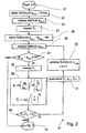
- the target pressure is increased in several stages (step 32) up to a maximum value and each stage the actual pressure ⁇ pi and the air flow V • i (Steps 26, 28, 28). After initialization, the measured pressure and flow values ⁇ p i or V • i stored for further use.
- V • the closest airflow measured during initialization
- V • i the closest airflow measured during initialization
- ⁇ p i the pressure drop
- V • i searched and ⁇ p i receives the sign of the measured flow.
- a disadvantage of this method is that during initialization very many pressure and flow values must be measured in order to determine the pressure drop sufficiently accurately.
- the pressure drop ⁇ p can be calculated between the measured flow values, for example by linear interpolation according to equation (3).
- the index i must still be determined, ie it must be the correct interval for the measured flow V • being found.
- Ap V • Ap i + Ap i + 1 - Ap i V • i + 1 - V • i ⁇ V • - V • i in which V • i ⁇ V • ⁇ V • i + 1
- the factor sign V • either the value 1 with air flow to the patient or -1 with air flow from the patient to take into account the flow direction.
- Linear interpolation is merely a mathematical process that is generally applicable but ignores the physical background of airflow through a hose.
- ⁇ p is the pressure falling on the hose
- ⁇ is a pressure loss coefficient of the hose
- ⁇ is a pipe friction value of the hose
- I is the length of the hose
- d is the diameter of the hose
- p is the density of the flowing medium, ie approx. 1.2 for CPAP devices kg / m 3 for air and v the cross-section averaged flow velocity from the CPAP device towards the mask.
- a has the value 2 for turbulent flows and 1 for laminar flows. In practice, a can also assume intermediate values because there is seldom an ideal-typical flow form. In the typical conditions with CPAP devices turbulent flows are present, so that a ⁇ 2.
- Equation (4) is also off Fluid Dynamics, JH Spurk, 4th edition, Springerverlag, Berlin, 1996 known, where ⁇ is referred to as the resistance number.
- V itself stands for an air volume.
- the dot denotes the derivative after time d / dt.
- V • is detected by the flow sensor 16.
- Equation (6) contains the two parameters C and a. Therefore, at least two measuring points at different pressures ⁇ p i and ⁇ p i + 1 and the corresponding flow values V • i such as V • i + 1 required to determine the two parameters.
- the parameters a i and C i for the interval i may be for a flow V • between V • i and V • i + 1 according to equations (7) and (8).
- the pressure drop ⁇ p then results from equation (9).
- the parameter a can be set to a value between 1 and 2. Only the parameter C i is calculated separately for each interval from equation (8). In this embodiment, only the one value a for all a i and the values C i and V • i saved for the subsequent therapy phase.
- step 27 it is checked in step 27 whether the setpoint pressure set by the microcontroller 5 and the actual pressure measured by the pressure sensor 11 differ by less than tolerance tol. If this is the case, still further pressure and flow pairs can be measured in steps 28 and 26. If this is not the case, the initialization is ended in step 33.
- the parameters a i and C i or only C i are calculated according to equations (7) and (8).
- the parameter C i for an interval i + 1 is in an allowable range between a lower value C u and an upper value C o .
- the parameter C summarizes the resistance number ⁇ , hose length I and hose diameter d together.
- C thus represents a kind of resistance of the tube. For example, if the patient sets up the mask during initialization, the calculated resistance value increases because it now results as a series connection of the tube 9 with the exhalation port 2.
- step 30 represents a plausibility check as to whether correct values are still being measured. Will the initialization in step 30
- equation (6) describes the pressure drop across a hose in a wide flow range to a good approximation, it may be sufficient that only at two different pressure values ⁇ p i the flow V • i is measured to determine the parameters a and C for the entire flow range. None of the pressures or flows may be zero, since in equation (7) must not be divided by zero and the logarithm of zero is not defined. Also, the flows must be different, otherwise their ratio is 1, the logarithm of 1 is zero, and zero can not be divided. This is the reason for steps 22 to 24 preceding the loop, in which a pressure-flux value pair is measured before the calculation of C 1 .
- the parameter a can be preset at the factory and only the flow can be determined to a single actual pressure ⁇ p. From this, only one parameter C is calculated according to equation (8).
- n pressure flow value pairs ⁇ p i and V • i are measured, where n ⁇ 3.
- the parameters C and a or only C in equation (6) can be adapted to these value pairs.
- fluctuations in the measured values due, for example, to noise are compensated.
- the measurement points can be divided into several intervals, each interval containing at least three measurement points, for each interval i, either only a parameter C i or a parameter C i and a parameter a i can be adjusted.
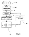
- Fig. 3 shows the behavior of a ventilator, especially a CPAP device during therapy.
- a therapy pressure p t is set in step 42. This can, as mentioned above, for example, be specified by a doctor.
- the air flow is measured by the flow sensor 16 in step 43. Is the function for calculating the pressure drop ⁇ p from the flow V • in sections as defined in equation (9), see above
- the correct interval i for the measured air flow is determined V • certainly. Crosses the river V • for example, when inhaling the highest flux value V n measured during initialization, the parameters for the highest interval n-1 are used.
- the pressure drop is determined in step 45 by means of equation (9).
- step 46 a new target pressure is calculated from equation (1) in step 46.
- the flow measurement is then repeated in step 43.
- the endless loop consisting of steps 43, 44, 45 and 46 is, as mentioned above, passed through at least twice per second so that the target pressure fluctuates according to the respiratory cycle of the patient in order to promptly close the pressure surge on the breathing tube to be able to compensate.
- there is a further pressure control loop which controls the rotational speed of the turbine so that the pressure measured by pressure sensor 11 corresponds as accurately as possible to setpoint pressure p.
- the in Fig. 2 and 3 shown steps executed by the microcontroller 5.
- the microcontroller can be connected via a data line 10 to a slot 7 into which a storage medium 6 is inserted.
- a storage medium 6 can be, for example, a memory stick or a PCMCIA card.
- slot 7 may be an IC socket for a PROM (Programmable Read Only Memory) device.
- the microcontroller 5 may include an EPROM (electrically PROM).
- the microcontroller itself is the storage medium that can be replaced.
Description
Die Erfindung betrifft ein Beatmungsgerät, das geeignet ist, den Druckabfall an einem Beatmungsschlauch zu kompensieren und ein Speichermedium zur Speicherung eines entsprechenden Programms.The invention relates to a ventilator which is suitable for compensating the pressure drop across a breathing tube and a storage medium for storing a corresponding program.
Bekannt sind Beatmungsgeräte oder Respiratoren zur maschinellen, künstlichen Beatmung bei allen Formen des Sauerstoffmangelzustands. Sie werden unter anderem für die Langzeitbeatmung eingesetzt. (
Bei frühen Beatmungsgeräten um 1950 wurden Scheibenwischermotoren als Antrieb für Blasebälge verwendet. Elektromotoren führten jedoch bei den damals verwendeten Ästhetika zu einer Explosionsgefahr. 1952 entwickelte Roger Manley vom Westminster-Krankenhaus in London ein Beatmungsgerät das ausschließlich von Gas angetrieben wurde. Dies war vier Jahrzehnte lang vor der Einführung elektronisch gesteuerte Beatmungsgeräte sehr populär. Seine Arbeitsweise war sehr einfach. Ein Gasfluss hob eine mit einem Gewicht beschwerte Blasebalgeinheit, die unter dem Einfluss der Schwerkraft immer wieder herunterfiel und dabei Beatmungsgase in die Lunge eines Patienten drückte. Der Beatmungsdruck konnte durch Verschieben des Gewichts auf den Blasebälgen eingestellt werden. Auch das Beatmungsvolumen konnte über eine Kurvenscheibe eingestellt werden, die die Auslenkung der Blasebälge begrenzte. Schließlich konnte der Restdruck nach Ende der Ausatmung eingestellt werden. Diese robuste Einheit beflügelte die Einführung von Überdruckbeatmungstechniken in Europa.In early ventilators around 1950, windshield wiper motors were used to drive bellows. Electric motors, however, led to the explosion of the aesthetics used at that time. In 1952, Roger Manley of Westminster Hospital in London developed a ventilator powered exclusively by gas. This was very popular for four decades before the introduction of electronically controlled ventilators. His way of working was very simple. A gas flow lifted a weighted bellows unit, which repeatedly fell under the influence of gravity, pushing respiratory gases into a patient's lungs. The ventilation pressure could be adjusted by shifting the weight on the bellows. Also, the ventilation volume could be adjusted via a cam, which limited the deflection of the bellows. Finally, the residual pressure could be adjusted after exhalation. This robust unit boosted the introduction of positive pressure ventilation techniques in Europe.
Volumengesteuerte Beatmung war in Europa erst 1971 mit dem SERVO 900 (Elema-Schönander) möglich.Volume-controlled ventilation was only possible in Europe in 1971 with the SERVO 900 (Elema-Schönander).
Die
Eine besondere Form von Beatmungsgeräten, so genannten CPAP-Geräte werden eingesetzt, um obstruktive Atmungsstörungen während des Schlafens zu vermeiden. Ein solches Gerät ist aus der
Obstruktive Atmungsstörungen führen zu Apnoen (Atemstillstand), durch die der Schlafende erwacht. Häufige Apnoen verhindern, dass der Schlafende in den erholsamen Tiefschlaf fällt. Menschen, die Apnoen während des Schlafens erleiden, sind deshalb tagsüber unausgeschlafen, was zu sozialen Problemen am Arbeitsplatz und im schlimmsten Fall zu tödlichen Unfällen, beispielsweise bei Berufskraftfahrern, führen kann.Obstructive respiratory disorders lead to apneas (respiratory arrest), which awakens the sleeping person. Frequent apneas prevent the sleeping person from relaxing in deep sleep. People who suffer apneas during sleep are therefore no sleep during the day, which can lead to social problems in the workplace and in the worst case to fatal accidents, for example in professional drivers.
Zur Behandlung von Apnoen wurde die CPAP (continuous positive airway pressure)-Therapie entwickelt, die in
Dieser Überdruck soll gewährleisten, dass die oberen Atemwege während der gesamten Nacht vollständig geöffnet bleiben und somit keine Apnoen auftreten (
Bei allen bekannten CPAP-Geräten und in der Patentliteratur werden bisher zwei Verfahren verwendet, um den Druck in der Gesichtsmaske von CPAP-Geräten zu bestimmen.In all known CPAP devices and in the patent literature, two methods have hitherto been used to determine the pressure in the face mask of CPAP devices.
Bei dem einen erfasst ein Drucksensor den Druck der zum Patienten geförderten Luft direkt im Gerät. Werksseitig wird für eine häufig verwendete Kombination von Beatmungsschlauch und Maske bei einem mittleren Volumenstrom die Druckdifferenz gemessen. Dieser Differenzwert wird vom im Gerät gemessenen Druck abgezogen und das Ergebnis als Maskendruck interpretiert. Zwangsläufig ergeben sich Fehler in der Druckeinstellung, weil der Luftstrom durch die Atmung ständig schwankt und damit der Druckverlust im Beatmungsschlauch variiert. Besonders lästig für die Patienten ist dabei, dass der Überdruck in der Gesichts - oder Nasenmaske beim Einatmen geringer ist als beim Ausatmen. Deshalb hat der Patient besonders bei dieser Form der Druckregelung das Gefühl, in der Summe gegen einen Widerstand atmen zu müssen.In one, a pressure sensor detects the pressure of the air delivered to the patient directly in the device. By default, the pressure difference is measured for a commonly used combination of breathing tube and mask at a medium flow rate. This difference value is subtracted from the pressure measured in the device and the result is interpreted as a mask pressure. Inevitably there are errors in the pressure setting, because the air flow fluctuates constantly through the breathing and thus varies the pressure loss in the breathing tube. Especially annoying for the patients is that the pressure in the face or nose mask when inhaling is less than exhaling. Therefore, especially in this form of pressure control, the patient has the feeling that he has to breathe in total against resistance.
Beim zweiten Verfahren wird der Druck beim Patienten über einen zusätzlichen Schlauch gemessen. Dieses Verfahren erzeugt einen stabilen Patientendruck, ist aber durch den zusätzlichen Schlauch nicht anwenderfreundlich und fehleranfällig. Beim anderen Verfahren, von denen eines in der
Es ist Aufgabe der Erfindung, ein Beatmungsgerät sowie ein Speichermedium mit einem entsprechenden Programm anzugeben, bei dem der Druckabfall am Beatmungsschlauch kompensiert wird.It is an object of the invention to provide a ventilator and a storage medium with a corresponding program in which the pressure drop is compensated on the breathing tube.
Diese Aufgabe wird durch die Lehre der unabhängigen Ansprüche gelöst.This object is achieved by the teaching of the independent claims.
Bevorzugte Ausführungsformen der Erfindung sind Gegenstand der Unteransprüche.Preferred embodiments of the invention are subject of the dependent claims.
Vorteilhaft an der Erfindung ist, dass die Herstellkosten des CPAP-Geräts sinken, weil keine speziellen Beatmungsschläuche verwendet werden müssen.An advantage of the invention is that the manufacturing costs of the CPAP device decrease, because no special ventilation hoses must be used.
Vorteilhaft am Messen des Luftflusses bei zwei unterschiedlichen Drücken ist, dass die beiden Parameter C und a in Gleichung 6 anhand von Messwerten bestimmt werden, so dass der während der Therapie für einen gemessenen Fluss bestimmte Druckabfall genauer dem tatsächlichen Druckabfall am Beatmungsschlauch entspricht.The advantage of measuring the air flow at two different pressures is that the two parameters C and a in
Bei je mehr Drücken der Fluss während der Initialisierungsphase bei abgesetzter Beatmungsmaske gemessen wird, desto genauer ist während der Therapie die Druckkompensation.The more pressure the flow is measured during the initialization phase with the respiratory mask on, the more accurate the pressure compensation during therapy.
Das Anpassen des Parameters C oder der Parameter C und a an eine Vielzahl von Druck- und Flusswerten reduziert den Einfluss möglicher Ausreißer bei den gemessenen Werten und vermeidet den Suchaufwand nach dem richtigen Intervall für eine abschnittsweise definierte Funktion.Adjusting parameter C or parameters C and a to a variety of pressure and flow values reduces the influence of possible outliers on the measured values and avoids the search effort for the proper interval for a sectioned function.
Das Verwerfen von während der Initialisierung gemessenen Drücken reduziert den Speicheraufwand in vorteilhafter Weise. Durch das abschnittsweise Anpassen des Parameters C oder der Parameter C und a in Gleichung 6 an Intervalle, an deren unteren und oberen Ende sowohl Druck als auch Fluss gemessen wurden, führt zu einer sehr genauen Übereinstimmung zwischen dem berechneten und dem tatsächlichen Druckabfall am Beatmungsschlauch. Ausreißer bei der Druck- oder Flussmessung beeinflussen nur die angrenzenden Intervalle.Discarding pressures measured during initialization advantageously reduces memory overhead. By adjusting parameter C or parameters C and a in Eqn. 6 at intervals where both pressure and flow were measured at the lower and upper extremities, there is a very close match between the calculated and actual pressure drops across the breathing tube. Outliers in pressure or flow measurement affect only the adjacent intervals.
Das Kriterium bei einer nennenswerten Differenz zwischen Solldruck und Istdruck, die Initialisierungsphase abzubrechen, ist vorteilhaft, weil hierdurch sowohl der gesamte zur Verfügung stehende Flussbereich durch Messpunkte abgedeckt wird als auch vermieden wird, dass beim maximalen Fluss mehrere Messpunkte aufgenommen werden. Letzteres führt zu einer unnötig langen Initialisierung.The criterion for a significant difference between target pressure and actual pressure to interrupt the initialization phase is advantageous because both the entire available flow range is covered by measuring points and it is avoided that several measurement points are recorded at the maximum flow. The latter leads to an unnecessarily long initialization.
Das Überprüfen, ob der Parameter C in einem vernünftigen Bereich liegt schon während des Messens der Druck- und Flusswerte während der Initialisierungsphase und dem Abbrechen der Initialisierungsphase, wenn der Parameter C nicht in einem vernünftigen Bereich liegt, stellt beispielsweise sicher, dass der Patient die Maske nicht bereits während der Initialisierung aufgesetzt hat.For example, verifying that the parameter C is within a reasonable range while measuring the pressure and flow values during the initialization phase and aborting the initialization phase when the parameter C is not within a reasonable range ensures that the patient is wearing the mask not already set up during initialization.
Die Verwendung eines gespeicherten Parameterwerts ist eine sinnvolle Rückfallposition, falls die Initialisierung nicht durchgeführt werden kann. Dies ist z.B. dann der Fall, wenn der Patient die Maske bereits bei ausgeschaltetem Gerät aufgesetzt hat.Using a stored parameter value is a useful fall back position if initialization can not be performed. This is e.g. then the case when the patient has already set up the mask when the device is switched off.
Das Verwenden von Istdruckwerten anstatt von Solldruckwerten beim erfindungsgemäßen Beatmungsgerät vermeidet Fehler bei Abweichungen zwischen Ist - und Solldruck.The use of actual pressure values instead of setpoint pressure values in the ventilator according to the invention avoids errors in the case of deviations between the actual pressure and the desired pressure.
Im Folgenden wird eine bevorzugte Ausführungsform der Erfindung unter Bezugnahme auf die beiliegenden Zeichnungen näher erläutert. Dabei zeigen:
-
Fig. 1 ein CPAP-Gerät; -
Fig. 2 ein Flussdiagramm eines erfindungsgemäßen Initialisierungsverfahrens; und -
Fig. 3 ein Flussdiagramm eines erfindungsgemäßen Verfahrens zur Druckabfallkompensation an einem Beatmungsschlauch.
-
Fig. 1 a CPAP device; -
Fig. 2 a flow chart of an initialization method according to the invention; and -
Fig. 3 a flow chart of a method according to the invention for pressure drop compensation on a breathing tube.
Wie oben erwähnt schwankt der Druckabfall am Beatmungsschlauch mit dem Luftfluss durch den Beatmungsschlauch. Der Luftfluss wiederum ändert sich während eines Atemzyklusses. Er ist insbesondere beim Einatmen hoch und beim Ausatmen niedrig und kann beim Ausatmen sogar sein Vorzeichen wechseln. Wird nun der vom Beatmungsgerät gelieferte Druck konstant gehalten, so ist der Druck in der Beatmungsmaske beim Ausatmen höher als beim Einatmen, was für den Patienten unangenehm ist. Hier schafft diese Erfindung dadurch Abhilfe, dass der gewünschte Therapiedruck pt, der möglichst gleich dem Maskendruck pm sein soll um den Druckabfall am Schlauch korrigiert wird. Als Solldruck p wird die Summe aus Therapiedruck pt und Druckabfall Δp eingestellt: 
Der Druckabfall Δp ist eine Funktion des Luftflusses: 
Um den Luftfluss zu messen, ist das erfindungsgemäße CPAP-Gerät mit einem Luftflusssensor 16 ausgerüstet. Der Luftflusssensor 16 kann den Luftfluss anhand des Wärmeverlustes eines Heizdrahts 17 bestimmen. Wie oben erwähnt schwankt der Luftfluss mit der Atmung des Patienten. Der Druckabfall Δp soll deshalb öfter während eines Atemzyklusses berechnet werden. Ein Atemzyklus dauert typischerweise zwischen 3 und 5 Sekunden, so dass der Druckabfall und der Solldruck mindestens zweimal pro Sekunde berechnet werden sollen.In order to measure the air flow, the CPAP device according to the invention is equipped with an
Gemäß der Erfindung wird nach Einschalten des Geräts und bevor der Patient 19 die Beatmungsmaske 18 aufsetzt, eine Initialisierung durchgeführt, deren Flussdiagramm in ![]()
![]()
![]()
![]()
![]()
![]()
![]()
![]()
![]()
![]()
Um mit weniger Druck- und Flusswerten auszukommen, kann zwischen den gemessenen Flusswerten beispielsweise durch lineare Interpolation gemäß Gleichung (3) der Druckabfall Δp berechnet werden. Bevor jedoch Gleichung (3) angewendet wird, muss noch der Index i bestimmt werden, d.h. es muss das richtige Intervall für den gemessenen Fluss ![]()

![]()
![]()
![]()
Dabei nimmt der Faktor sign![]()
![]()
Die lineare Interpolation ist lediglich ein mathematisches Verfahren, das zwar allgemein einsetzbar ist, jedoch die physikalischen Hintergründe des Luftflusses durch einen Schlauch ignoriert. Um die Anzahl von erforderlichen Messwerten Δpi und ![]()

![]()
Dabei ist Δp der am Schlauch abfallende Druck, ξ ein Druckverlustbeiwert des Schlauches, λ ein Rohrreibungswert des Schlauches, I die Länge des Schlauches, d der Durchmesser des Schlauches, p die Dichte des strömenden Mediums, also bei CPAP-Geräten ca. 1,2 kg/m3 für Luft und v die über den Querschnitt gemittelten Strömungsgeschwindigkeit vom CPAP-Gerät in Richtung Maske. a hat den Wert 2 für turbulente Strömungen und 1 für laminare Strömungen. In der Praxis kann a auch Zwischenwerte annehmen, weil selten eine ideal-typische Strömungsform vorliegt. Bei den typischen Verhältnissen bei CPAP-Geräten liegen turbulente Strömungen vor, so dass a ≈ 2 ist. Die Gleichung (4) ist auch aus ![]()

![]()
V selbst steht für ein Luftvolumen. Der Punkt bezeichnet die Ableitung nach der Zeit d/dt.![]()
![]()
Setzt man (2) in (1) ein, erhält man folgende quadratische Abhängigkeit des Druckabfalls Δp vom Luftstrom ![]()

![]()
Gleichung (6) enthält die zwei Parameter C und a. Deshalb sind mindestens zwei Messpunkte bei unterschiedlichen Drücken Δpi und Δpi+1 sowie die entsprechenden Flusswerte![]()
![]()
![]()
![]()
![]()


![]()
![]()
![]()
![]()
![]()
![]()
![]()
Wie man aus Gleichung (9) sieht, kommen hier die gemessenen Druckwerte des Δpi nicht mehr vor. Nach der Initialisierung müssen also lediglich die Flusswerte ![]()
![]()
In einer anderen Ausführungsform kann der Parameter a auf einen Wert zwischen 1 und 2 gesetzt werden. Nur der Parameter Ci wird für jedes Intervall getrennt aus Gleichung (8) berechnet. In dieser Ausführungsform wird nur der eine Wert a für alle ai sowie die Werte Ci und![]()
![]()
Die während der Initialisierung gemessenen Druck- und Flusswerte Δpi bzw. ![]()
![]()
Vorzugsweise werden bereits während der Initialisierung für jedes Messintervall in Schritt 29 die Parameter ai und Ci oder nur Ci nach Gleichungen (7) und (8) berechnet. So kann in Schritt 30 überprüft werden, ob der Parameter Ci für ein Intervall i+1 in einem erlaubten Bereich zwischen einem unteren Wert Cu und einem oberen Wert Co liegt. Wie oben erwähnt fasst der Parameter C die Widerstandszahl η, Schlauchlänge I sowie Schlauchdurchmesser d zusammen. C stellt somit eine Art Widerstand des Schlauches dar. Setzt beispielsweise der Patient die Maske während der Initialisierung auf, steigt der berechnete Widerstandswert an, weil er sich jetzt als Serienschaltung des Schlauchs 9 mit der Ausatemöffnung 2 ergibt. Somit stellt Schritt 30 eine Plausibilitätskontrolle dar, ob noch richtige Werte gemessen werden. Wird die Initialisierung in Schritt 30Preferably, during the initialization for each measurement interval in
abgebrochen, so werden die bis dahin gemessenen Werte![]()
![]()
Da Gleichung (6) den Druckabfall an einem Schlauch in einem weiten Flussbereich in guter Näherung beschreibt, kann es ausreichen, dass lediglich bei zwei unterschiedlichen Druckwerten Δpi der Fluss ![]()
![]()
In einer weiteren Ausführungsform kann der Parameter a werkseitig vorgegeben werden und lediglich der Fluss zu einem einzigen Istdruck Δp bestimmt werden. Hieraus wird nach Gleichung (8) lediglich ein Parameter C berechnet.In a further embodiment, the parameter a can be preset at the factory and only the flow can be determined to a single actual pressure Δp. From this, only one parameter C is calculated according to equation (8).
In einer weiteren Ausführungsform können n Druck-Flusswertepaare Δpi und ![]()
![]()
![]()
![]()
![]()
![]()
![]()
![]()
In dem erfindungsgemäßen CPAP-Gerät werden die in
Claims (11)
- Ventilator, comprising:a fan (8),a connection for a ventilator tube (9), which is pneumatically connected to the outlet of the fan (8);a flow sensor (16) for measuring the air conveyed from the fan to the connection for the ventilator tube (9); anda controller (5), which is electrically connected to the flow sensor (16) and the fan (8), wherein the controller (5) is determined and adapted to carry out the following:measuring (24, 28) a first air flow by the flow sensor (16) at a first pressure in the connection for the ventilator tube (9) and with the respiratory mask taken off;calculating (29) a parameter in a function providing the pressure drop in the ventilator tube (9) in dependence on the air flow, wherein the parameter for the first air flow and the first pressure is calculated;measuring (43) the air flow by the flow sensor (16) with the respiratory mask being put on;calculating a correction pressure (44, 45) by means of the function for the measured air flow; andsetting a target pressure (46), which was determined as sum of the selected mask pressure and the correction pressure.
- Ventilator according to claim 1, wherein the controller (5) is further determined and adapted to
determine a second air flow (28) by the flow sensor (16) at a second pressure (32) at the connection for a ventilator tube (9) unequal to the first pressure and with the respiratory mask taken off, and calculate the first parameter and a second parameter of the function, wherein both parameters are calculated from the first and second air flow and the first and second pressure. - Ventilator according to claim 2, wherein the controller (5) is further determined and adapted to
set (32) a plurality of pressures at the ventilator on connecting the ventilator tube (9), with the respiratory mask taken off; and
measure the air flow by the flow sensor (16) at each of the plurality of pressures. - Ventilator according to claim 3, wherein the controller (5) is further determined and adapted to calculate a parameter of the function such that the pressures calculated from the measured air flows by the function optimally correspond to the set pressures.
- Ventilator according to one of claims 1 to 4, wherein the controller (5) is further determined and adapted to store (31), after the calculation of the parameter or the parameters, only the parameter(s), but not the pressures set with the respiratory mask taken off.
- Ventilator according to claim 3, wherein the controller (5) is further determined and adapted to calculate (29) for each interval between two flows measured with the respiratory mask taken off the parameter for the function from the flows limiting the interval and the corresponding pressures and, when calculating the correction pressure, to search (44) at first the interval between two pressures measured with the respiratory mask taken off and use the parameter for the interval in the function.
- Ventilator according to one of claims 3 to 6, wherein the controller (5) is further determined and adapted to monotonously increase the height of the pressures during the setting of the plurality of pressures and not to set further pressures if the difference between a predefined target pressure and a measured actual pressure exceeds a predetermined value.
- Ventilator according to claim 6 or 7, in as far as claim 7 relates to claim 6, wherein the controller (5) is further determined and adapted to calculate (29) the parameters for a flow interval after the controller (5) has determined (28) the two flows at the interval boundaries in interaction with the flow sensor (16) and set (32) the corresponding pressures at the ventilator, and before the controller (5) sets (32) another pressure, wherein the controller (5) only sets (30) another pressure if the parameter is within a predefined interval.
- Ventilator according to one of claims 1 to 8, wherein the controller (5) is further determined and adapted to check whether the calculated parameter is (30) within a predefined range and, if this is not the case, a stored parameter value is used.
- Ventilator according to one of claims 1 to 9, wherein the ventilator further comprises a pressure sensor (11) which is electrically connected to the controller (5), wherein the controller (5) uses actual pressure values (26) measured by the pressure sensor (11) for calculating the parameter or the parameters.
- Memory medium for use with a ventilator, comprising a microcontroller (5) for processing the commands stored in the memory medium, wherein the microcontroller (5) performs the following during the processing of the commands stored in the memory medium in order to compensate the pressure drop in a ventilator tube (9):measuring (24, 28) a first air flow at a first pressure in the connection for the ventilator tube (9) and with the respiratory mask taken off;calculating (29) a parameter in a function providing the pressure drop in the ventilator tube (9) in dependence on the air flow, wherein the parameter for the first air flow and the first pressure is calculated;measuring the air flow (43) with the respiratory mask being put on;calculating a correction pressure (44, 45) by means of the function for the measured air flow;setting a target pressure (46), which was determined as sum of the selected mask pressure and the correction pressure.
Applications Claiming Priority (3)
| Application Number | Priority Date | Filing Date | Title |
|---|---|---|---|
| DE10253947A DE10253947C1 (en) | 2002-11-19 | 2002-11-19 | Pressure loss compensation method for respiration device with calculation of pressure loss from measured air flow |
| DE10253947 | 2002-11-19 | ||
| PCT/DE2003/003592 WO2004045670A2 (en) | 2002-11-19 | 2003-10-29 | Method for compensating a pressure drop in a ventilator tube, ventilator and memory medium |
Publications (2)
| Publication Number | Publication Date |
|---|---|
| EP1562655A1 EP1562655A1 (en) | 2005-08-17 |
| EP1562655B1 true EP1562655B1 (en) | 2012-12-19 |
Family
ID=29414354
Family Applications (1)
| Application Number | Title | Priority Date | Filing Date |
|---|---|---|---|
| EP03811335A Expired - Lifetime EP1562655B1 (en) | 2002-11-19 | 2003-10-29 | Method for compensating a pressure drop in a ventilator tube, ventilator and memory medium |
Country Status (7)
| Country | Link |
|---|---|
| US (1) | US7367338B2 (en) |
| EP (1) | EP1562655B1 (en) |
| JP (1) | JP4460456B2 (en) |
| AU (1) | AU2003302002A1 (en) |
| DE (1) | DE10253947C1 (en) |
| ES (1) | ES2400854T3 (en) |
| WO (1) | WO2004045670A2 (en) |
Cited By (1)
| Publication number | Priority date | Publication date | Assignee | Title |
|---|---|---|---|---|
| DE102015103894A1 (en) | 2015-03-17 | 2016-09-22 | Fritz Stephan Gmbh Medizintechnik | Respirators and control methods for ventilators |
Families Citing this family (25)
| Publication number | Priority date | Publication date | Assignee | Title |
|---|---|---|---|---|
| US8578937B2 (en) | 2004-09-21 | 2013-11-12 | Medtronic Xomed, Inc. | Smart mandibular repositioning system |
| US9526852B2 (en) | 2005-10-21 | 2016-12-27 | Resmed Limited | Method and apparatus for improving flow and pressure estimation in CPAP systems |
| WO2007062400A2 (en) | 2005-11-23 | 2007-05-31 | Jianguo Sun | Method and apparatus for providing positive airway pressure to a patient |
| DE102006032620B3 (en) * | 2006-07-13 | 2007-11-22 | Hoffrichter Gmbh | Respirator for treatment of obstructive sleep apnea, has controller determining loss pressure, resulting over respiratory tract resistance of tract of patient, and for proportional adjustment of therapy pressure progress |
| US9028423B2 (en) * | 2006-08-30 | 2015-05-12 | Resmed Limited | Distinguishing closed and open respiratory airway apneas by complex admittance values |
| US7788963B2 (en) * | 2006-10-31 | 2010-09-07 | Ric Investments, Llc | System and method for calibrating a determination of partial pressure of one or more gaseous analytes |
| CN101541367B (en) * | 2006-11-08 | 2014-02-26 | 雷斯梅德有限公司 | Conduit for use in a respiratory apparatus |
| US20090020122A1 (en) * | 2007-07-16 | 2009-01-22 | Helmut Hoffrichter | Respiratory device for treating obstructive sleep apnea and method for controlling said device |
| DE102008005558A1 (en) | 2008-01-22 | 2009-07-30 | Hoffrichter Gmbh | External respiration system pressure loss compensating method for lung ventilator to treat obstructive sleep apnea of patient, involves guiding measurement value of pressure difference to regulating device as control variable |
| WO2009112076A1 (en) * | 2008-03-13 | 2009-09-17 | Hoffrichter Gmbh | Respirator having variable pressure support |
| US8528554B2 (en) | 2008-09-04 | 2013-09-10 | Covidien Lp | Inverse sawtooth pressure wave train purging in medical ventilators |
| EP2329232B1 (en) * | 2008-09-30 | 2012-09-19 | Nellcor Puritan Bennett LLC | Pneumatic tilt sensor for use with respiratory flow sensing device |
| US8707954B2 (en) * | 2008-10-09 | 2014-04-29 | Daniel A. McCarthy | Air/oxygen supply system and method |
| US20100288283A1 (en) * | 2009-05-15 | 2010-11-18 | Nellcor Puritan Bennett Llc | Dynamic adjustment of tube compensation factor based on internal changes in breathing tube |
| EP2496297B1 (en) * | 2009-11-03 | 2020-09-16 | ResMed Pty Ltd | Cpap systems |
| US20110146683A1 (en) * | 2009-12-21 | 2011-06-23 | Nellcor Puritan Bennett Llc | Sensor Model |
| US8844521B2 (en) | 2010-04-09 | 2014-09-30 | Daniel A. McCarthy | Air/oxygen ventilator system and method |
| US8776792B2 (en) | 2011-04-29 | 2014-07-15 | Covidien Lp | Methods and systems for volume-targeted minimum pressure-control ventilation |
| US9327089B2 (en) | 2012-03-30 | 2016-05-03 | Covidien Lp | Methods and systems for compensation of tubing related loss effects |
| JP6678454B2 (en) | 2012-10-10 | 2020-04-08 | コーニンクレッカ フィリップス エヌ ヴェKoninklijke Philips N.V. | Adaptive patient circuit compensation by pressure sensor in mask device |
| CN103893865B (en) * | 2012-12-26 | 2017-05-31 | 北京谊安医疗系统股份有限公司 | A kind of method of lung ventilator turbine volume controlled ventilation |
| CN103893864B (en) * | 2012-12-26 | 2017-05-24 | 北京谊安医疗系统股份有限公司 | Turbine respirator pressure control ventilation method |
| DE102015003385B4 (en) * | 2015-03-17 | 2018-07-19 | Dräger Safety AG & Co. KGaA | Powered Air Purifying Respiratory System |
| US10556074B2 (en) | 2015-07-17 | 2020-02-11 | Daniel A. McCarthy | Artificial respiration system with timing control and automatic mask detection |
| US10478586B2 (en) | 2016-03-02 | 2019-11-19 | Daniel A. McCarthy | Artificial respiration system and method having automatic mask detection |
Citations (10)
| Publication number | Priority date | Publication date | Assignee | Title |
|---|---|---|---|---|
| US5551419A (en) * | 1994-12-15 | 1996-09-03 | Devilbiss Health Care, Inc. | Control for CPAP apparatus |
| US5694923A (en) * | 1996-08-30 | 1997-12-09 | Respironics, Inc. | Pressure control in a blower-based ventilator |
| WO1999022793A1 (en) * | 1997-11-03 | 1999-05-14 | Resmed Limited | A muffler for an apparatus for supplying breathable gas |
| WO2000027457A1 (en) * | 1998-11-05 | 2000-05-18 | Resmed Ltd. | Fault diagnosis in cpap and nippv devices |
| US6085747A (en) * | 1991-06-14 | 2000-07-11 | Respironics, Inc. | Method and apparatus for controlling sleep disorder breathing |
| US6105575A (en) * | 1994-06-03 | 2000-08-22 | Respironics, Inc. | Method and apparatus for providing positive airway pressure to a patient |
| WO2001032069A2 (en) * | 1999-11-01 | 2001-05-10 | Respironics, Inc. | Apparatus for controlling a medical device |
| US20020005197A1 (en) * | 1994-10-14 | 2002-01-17 | Devries Douglas F. | Portable drag compressor powered mechanical ventilator |
| US20020023644A1 (en) * | 1996-09-23 | 2002-02-28 | Michael Berthon-Jones | Assisted ventilation to match patient respiratory need |
| WO2002020076A2 (en) * | 2000-09-05 | 2002-03-14 | Mallinckrodt, Inc. | Adaptive inverse control of pressure based ventilation |
Family Cites Families (4)
| Publication number | Priority date | Publication date | Assignee | Title |
|---|---|---|---|---|
| DE19849571B4 (en) * | 1998-10-27 | 2004-12-02 | Map Medizin-Technologie Gmbh | Ventilator for supplying a breathing gas to a patient under a treatment pressure that is matched to the patient |
| FR2793145B1 (en) * | 1999-05-04 | 2003-10-24 | Map Medizintechnik Fur Arzt Un | DEVICE FOR SUPPLYING RESPIRATORY GAS TO SURPRESSION AND CONTROL ARRANGEMENT FOR CONTROLLING THE SAME |
| CA2424358A1 (en) * | 2000-10-19 | 2002-04-25 | Mallinckrodt Inc. | Ventilator with dual gas supply |
| US7168429B2 (en) * | 2001-10-12 | 2007-01-30 | Ric Investments, Llc | Auto-titration pressure support system and method of using same |
-
2002
- 2002-11-19 DE DE10253947A patent/DE10253947C1/en not_active Expired - Fee Related
-
2003
- 2003-10-29 JP JP2004552380A patent/JP4460456B2/en not_active Expired - Fee Related
- 2003-10-29 WO PCT/DE2003/003592 patent/WO2004045670A2/en active Application Filing
- 2003-10-29 EP EP03811335A patent/EP1562655B1/en not_active Expired - Lifetime
- 2003-10-29 ES ES03811335T patent/ES2400854T3/en not_active Expired - Lifetime
- 2003-10-29 AU AU2003302002A patent/AU2003302002A1/en not_active Abandoned
-
2005
- 2005-05-19 US US11/132,544 patent/US7367338B2/en not_active Expired - Fee Related
Patent Citations (10)
| Publication number | Priority date | Publication date | Assignee | Title |
|---|---|---|---|---|
| US6085747A (en) * | 1991-06-14 | 2000-07-11 | Respironics, Inc. | Method and apparatus for controlling sleep disorder breathing |
| US6105575A (en) * | 1994-06-03 | 2000-08-22 | Respironics, Inc. | Method and apparatus for providing positive airway pressure to a patient |
| US20020005197A1 (en) * | 1994-10-14 | 2002-01-17 | Devries Douglas F. | Portable drag compressor powered mechanical ventilator |
| US5551419A (en) * | 1994-12-15 | 1996-09-03 | Devilbiss Health Care, Inc. | Control for CPAP apparatus |
| US5694923A (en) * | 1996-08-30 | 1997-12-09 | Respironics, Inc. | Pressure control in a blower-based ventilator |
| US20020023644A1 (en) * | 1996-09-23 | 2002-02-28 | Michael Berthon-Jones | Assisted ventilation to match patient respiratory need |
| WO1999022793A1 (en) * | 1997-11-03 | 1999-05-14 | Resmed Limited | A muffler for an apparatus for supplying breathable gas |
| WO2000027457A1 (en) * | 1998-11-05 | 2000-05-18 | Resmed Ltd. | Fault diagnosis in cpap and nippv devices |
| WO2001032069A2 (en) * | 1999-11-01 | 2001-05-10 | Respironics, Inc. | Apparatus for controlling a medical device |
| WO2002020076A2 (en) * | 2000-09-05 | 2002-03-14 | Mallinckrodt, Inc. | Adaptive inverse control of pressure based ventilation |
Cited By (4)
| Publication number | Priority date | Publication date | Assignee | Title |
|---|---|---|---|---|
| DE102015103894A1 (en) | 2015-03-17 | 2016-09-22 | Fritz Stephan Gmbh Medizintechnik | Respirators and control methods for ventilators |
| WO2016146102A1 (en) | 2015-03-17 | 2016-09-22 | Fritz Stephan Gmbh Medizintechnik | Respirators and control methods for respirators |
| EP3653248A2 (en) | 2015-03-17 | 2020-05-20 | Fritz Stephan GmbH Medizintechnik | Respirators and control methods for respirators |
| EP4140525A2 (en) | 2015-03-17 | 2023-03-01 | Fritz Stephan GmbH | Respirators and control methods for respirators |
Also Published As
| Publication number | Publication date |
|---|---|
| JP2006506137A (en) | 2006-02-23 |
| AU2003302002A1 (en) | 2004-06-15 |
| JP4460456B2 (en) | 2010-05-12 |
| DE10253947C1 (en) | 2003-12-04 |
| US7367338B2 (en) | 2008-05-06 |
| ES2400854T3 (en) | 2013-04-12 |
| EP1562655A1 (en) | 2005-08-17 |
| WO2004045670A2 (en) | 2004-06-03 |
| US20050241640A1 (en) | 2005-11-03 |
Similar Documents
| Publication | Publication Date | Title |
|---|---|---|
| EP1562655B1 (en) | Method for compensating a pressure drop in a ventilator tube, ventilator and memory medium | |
| DE69736808T2 (en) | DETERMINATION OF LEAKAGE FLOW | |
| US8312879B2 (en) | Method and apparatus for airway compensation control | |
| DE10322964B4 (en) | Control unit for anti-snoring device and anti-snoring device | |
| DE60037636T2 (en) | Method of assessing pulmonary stress and a respiratory device | |
| EP3027252B1 (en) | Medical measuring device, ventilation device and method for operating a medical measuring device | |
| DE102005010488A1 (en) | Apparatus for administering a breathing gas and method for adjusting at least temporarily alternating breathing gas pressures | |
| DE19880497B4 (en) | Device for automated ventilation by positive air pressure on the respiratory tract | |
| EP0891199A1 (en) | Device and process for monitoring the respiration parameters of an artificial respiration system | |
| EP3270993B1 (en) | Respirators | |
| DE102010010248A1 (en) | Ventilation method and ventilator | |
| EP1878457A2 (en) | Ventilator device for treating obstructive sleep apnea and method for its control | |
| WO2003049793A2 (en) | Method for controlling the differential pressure in a cpap device and corresponding cpap device | |
| EP3858415B1 (en) | Device for humidifying respiratory gas | |
| WO2004045693A2 (en) | Method for controlling the pressure provided by a cpap device, cpap device and storage medium | |
| WO2004045669A2 (en) | Ventilator method, ventilator and memory medium | |
| EP3524306A1 (en) | Artificial respiration device and control and test method | |
| WO2003059426A2 (en) | Method for determining a mask pressure, air flow and/or air pressure in a cpap device, cpap device and corresponding test equipment | |
| EP3840812A1 (en) | Method for operating an actuator in a medical apparatus, and device therefor | |
| EP4129376A1 (en) | Device for ventilating with controlled pressure transition | |
| DE102004046991A1 (en) | Nose mask for use with respirator, has thermopile for collecting airflow caused by mouth respiration |
Legal Events
| Date | Code | Title | Description |
|---|---|---|---|
| PUAI | Public reference made under article 153(3) epc to a published international application that has entered the european phase |
Free format text: ORIGINAL CODE: 0009012 |
|
| 17P | Request for examination filed |
Effective date: 20050609 |
|
| AK | Designated contracting states |
Kind code of ref document: A1 Designated state(s): AT BE BG CH CY CZ DE DK EE ES FI FR GB GR HU IE IT LI LU MC NL PT RO SE SI SK TR |
|
| AX | Request for extension of the european patent |
Extension state: AL LT LV MK |
|
| DAX | Request for extension of the european patent (deleted) | ||
| 17Q | First examination report despatched |
Effective date: 20090804 |
|
| RAP1 | Party data changed (applicant data changed or rights of an application transferred) |
Owner name: CAREFUSION GERMANY 234 GMBH |
|
| REG | Reference to a national code |
Ref country code: DE Ref legal event code: R079 Ref document number: 50314627 Country of ref document: DE Free format text: PREVIOUS MAIN CLASS: A61M0001000000 Ipc: A61M0016000000 |
|
| RIC1 | Information provided on ipc code assigned before grant |
Ipc: A61M 16/00 20060101AFI20111221BHEP |
|
| RTI1 | Title (correction) |
Free format text: METHOD FOR COMPENSATING A PRESSURE DROP IN A VENTILATOR TUBE, VENTILATOR AND MEMORY MEDIUM |
|
| GRAP | Despatch of communication of intention to grant a patent |
Free format text: ORIGINAL CODE: EPIDOSNIGR1 |
|
| GRAS | Grant fee paid |
Free format text: ORIGINAL CODE: EPIDOSNIGR3 |
|
| GRAA | (expected) grant |
Free format text: ORIGINAL CODE: 0009210 |
|
| AK | Designated contracting states |
Kind code of ref document: B1 Designated state(s): AT BE BG CH CY CZ DE DK EE ES FI FR GB GR HU IE IT LI LU MC NL PT RO SE SI SK TR |
|
| REG | Reference to a national code |
Ref country code: GB Ref legal event code: FG4D Free format text: NOT ENGLISH |
|
| REG | Reference to a national code |
Ref country code: CH Ref legal event code: EP |
|
| REG | Reference to a national code |
Ref country code: AT Ref legal event code: REF Ref document number: 589037 Country of ref document: AT Kind code of ref document: T Effective date: 20130115 |
|
| REG | Reference to a national code |
Ref country code: DE Ref legal event code: R096 Ref document number: 50314627 Country of ref document: DE Effective date: 20130221 |
|
| REG | Reference to a national code |
Ref country code: NL Ref legal event code: T3 |
|
| REG | Reference to a national code |
Ref country code: ES Ref legal event code: FG2A Ref document number: 2400854 Country of ref document: ES Kind code of ref document: T3 Effective date: 20130412 |
|
| PG25 | Lapsed in a contracting state [announced via postgrant information from national office to epo] |
Ref country code: SE Free format text: LAPSE BECAUSE OF FAILURE TO SUBMIT A TRANSLATION OF THE DESCRIPTION OR TO PAY THE FEE WITHIN THE PRESCRIBED TIME-LIMIT Effective date: 20121219 Ref country code: FI Free format text: LAPSE BECAUSE OF FAILURE TO SUBMIT A TRANSLATION OF THE DESCRIPTION OR TO PAY THE FEE WITHIN THE PRESCRIBED TIME-LIMIT Effective date: 20121219 |
|
| PG25 | Lapsed in a contracting state [announced via postgrant information from national office to epo] |
Ref country code: SI Free format text: LAPSE BECAUSE OF FAILURE TO SUBMIT A TRANSLATION OF THE DESCRIPTION OR TO PAY THE FEE WITHIN THE PRESCRIBED TIME-LIMIT Effective date: 20121219 Ref country code: GR Free format text: LAPSE BECAUSE OF FAILURE TO SUBMIT A TRANSLATION OF THE DESCRIPTION OR TO PAY THE FEE WITHIN THE PRESCRIBED TIME-LIMIT Effective date: 20130320 |
|
| PG25 | Lapsed in a contracting state [announced via postgrant information from national office to epo] |
Ref country code: BG Free format text: LAPSE BECAUSE OF FAILURE TO SUBMIT A TRANSLATION OF THE DESCRIPTION OR TO PAY THE FEE WITHIN THE PRESCRIBED TIME-LIMIT Effective date: 20130319 Ref country code: EE Free format text: LAPSE BECAUSE OF FAILURE TO SUBMIT A TRANSLATION OF THE DESCRIPTION OR TO PAY THE FEE WITHIN THE PRESCRIBED TIME-LIMIT Effective date: 20121219 Ref country code: CY Free format text: LAPSE BECAUSE OF FAILURE TO SUBMIT A TRANSLATION OF THE DESCRIPTION OR TO PAY THE FEE WITHIN THE PRESCRIBED TIME-LIMIT Effective date: 20121219 Ref country code: SK Free format text: LAPSE BECAUSE OF FAILURE TO SUBMIT A TRANSLATION OF THE DESCRIPTION OR TO PAY THE FEE WITHIN THE PRESCRIBED TIME-LIMIT Effective date: 20121219 Ref country code: CZ Free format text: LAPSE BECAUSE OF FAILURE TO SUBMIT A TRANSLATION OF THE DESCRIPTION OR TO PAY THE FEE WITHIN THE PRESCRIBED TIME-LIMIT Effective date: 20121219 |
|
| PG25 | Lapsed in a contracting state [announced via postgrant information from national office to epo] |
Ref country code: PT Free format text: LAPSE BECAUSE OF FAILURE TO SUBMIT A TRANSLATION OF THE DESCRIPTION OR TO PAY THE FEE WITHIN THE PRESCRIBED TIME-LIMIT Effective date: 20130419 Ref country code: RO Free format text: LAPSE BECAUSE OF FAILURE TO SUBMIT A TRANSLATION OF THE DESCRIPTION OR TO PAY THE FEE WITHIN THE PRESCRIBED TIME-LIMIT Effective date: 20121219 |
|
| PLBE | No opposition filed within time limit |
Free format text: ORIGINAL CODE: 0009261 |
|
| STAA | Information on the status of an ep patent application or granted ep patent |
Free format text: STATUS: NO OPPOSITION FILED WITHIN TIME LIMIT |
|
| PG25 | Lapsed in a contracting state [announced via postgrant information from national office to epo] |
Ref country code: DK Free format text: LAPSE BECAUSE OF FAILURE TO SUBMIT A TRANSLATION OF THE DESCRIPTION OR TO PAY THE FEE WITHIN THE PRESCRIBED TIME-LIMIT Effective date: 20121219 |
|
| 26N | No opposition filed |
Effective date: 20130920 |
|
| REG | Reference to a national code |
Ref country code: DE Ref legal event code: R097 Ref document number: 50314627 Country of ref document: DE Effective date: 20130920 |
|
| BERE | Be: lapsed |
Owner name: CAREFUSION GERMANY 234 G.M.B.H. Effective date: 20131031 |
|
| PG25 | Lapsed in a contracting state [announced via postgrant information from national office to epo] |
Ref country code: MC Free format text: LAPSE BECAUSE OF FAILURE TO SUBMIT A TRANSLATION OF THE DESCRIPTION OR TO PAY THE FEE WITHIN THE PRESCRIBED TIME-LIMIT Effective date: 20121219 |
|
| REG | Reference to a national code |
Ref country code: CH Ref legal event code: PL |
|
| REG | Reference to a national code |
Ref country code: IE Ref legal event code: MM4A |
|
| PG25 | Lapsed in a contracting state [announced via postgrant information from national office to epo] |
Ref country code: CH Free format text: LAPSE BECAUSE OF NON-PAYMENT OF DUE FEES Effective date: 20131031 Ref country code: LI Free format text: LAPSE BECAUSE OF NON-PAYMENT OF DUE FEES Effective date: 20131031 |
|
| PG25 | Lapsed in a contracting state [announced via postgrant information from national office to epo] |
Ref country code: BE Free format text: LAPSE BECAUSE OF NON-PAYMENT OF DUE FEES Effective date: 20131031 |
|
| PG25 | Lapsed in a contracting state [announced via postgrant information from national office to epo] |
Ref country code: IE Free format text: LAPSE BECAUSE OF NON-PAYMENT OF DUE FEES Effective date: 20131029 |
|
| REG | Reference to a national code |
Ref country code: AT Ref legal event code: MM01 Ref document number: 589037 Country of ref document: AT Kind code of ref document: T Effective date: 20131029 |
|
| PG25 | Lapsed in a contracting state [announced via postgrant information from national office to epo] |
Ref country code: AT Free format text: LAPSE BECAUSE OF NON-PAYMENT OF DUE FEES Effective date: 20131029 |
|
| PG25 | Lapsed in a contracting state [announced via postgrant information from national office to epo] |
Ref country code: TR Free format text: LAPSE BECAUSE OF FAILURE TO SUBMIT A TRANSLATION OF THE DESCRIPTION OR TO PAY THE FEE WITHIN THE PRESCRIBED TIME-LIMIT Effective date: 20121219 |
|
| PG25 | Lapsed in a contracting state [announced via postgrant information from national office to epo] |
Ref country code: LU Free format text: LAPSE BECAUSE OF NON-PAYMENT OF DUE FEES Effective date: 20131029 Ref country code: HU Free format text: LAPSE BECAUSE OF FAILURE TO SUBMIT A TRANSLATION OF THE DESCRIPTION OR TO PAY THE FEE WITHIN THE PRESCRIBED TIME-LIMIT; INVALID AB INITIO Effective date: 20031029 |
|
| REG | Reference to a national code |
Ref country code: FR Ref legal event code: ST Effective date: 20150630 |
|
| PG25 | Lapsed in a contracting state [announced via postgrant information from national office to epo] |
Ref country code: FR Free format text: LAPSE BECAUSE OF NON-PAYMENT OF DUE FEES Effective date: 20141031 |
|
| REG | Reference to a national code |
Ref country code: FR Ref legal event code: RN Effective date: 20150717 |
|
| REG | Reference to a national code |
Ref country code: FR Ref legal event code: D3 Effective date: 20150904 |
|
| PGRI | Patent reinstated in contracting state [announced from national office to epo] |
Ref country code: FR Effective date: 20150904 |
|
| REG | Reference to a national code |
Ref country code: FR Ref legal event code: PLFP Year of fee payment: 14 |
|
| REG | Reference to a national code |
Ref country code: FR Ref legal event code: PLFP Year of fee payment: 15 |
|
| PGFP | Annual fee paid to national office [announced via postgrant information from national office to epo] |
Ref country code: GB Payment date: 20170925 Year of fee payment: 15 Ref country code: FR Payment date: 20170921 Year of fee payment: 15 Ref country code: IT Payment date: 20170921 Year of fee payment: 15 |
|
| PGFP | Annual fee paid to national office [announced via postgrant information from national office to epo] |
Ref country code: NL Payment date: 20170925 Year of fee payment: 15 |
|
| PGFP | Annual fee paid to national office [announced via postgrant information from national office to epo] |
Ref country code: DE Payment date: 20170920 Year of fee payment: 15 |
|
| PGFP | Annual fee paid to national office [announced via postgrant information from national office to epo] |
Ref country code: ES Payment date: 20171103 Year of fee payment: 15 |
|
| REG | Reference to a national code |
Ref country code: DE Ref legal event code: R119 Ref document number: 50314627 Country of ref document: DE |
|
| REG | Reference to a national code |
Ref country code: NL Ref legal event code: MM Effective date: 20181101 |
|
| GBPC | Gb: european patent ceased through non-payment of renewal fee |
Effective date: 20181029 |
|
| PG25 | Lapsed in a contracting state [announced via postgrant information from national office to epo] |
Ref country code: DE Free format text: LAPSE BECAUSE OF NON-PAYMENT OF DUE FEES Effective date: 20190501 Ref country code: NL Free format text: LAPSE BECAUSE OF NON-PAYMENT OF DUE FEES Effective date: 20181101 |
|
| PG25 | Lapsed in a contracting state [announced via postgrant information from national office to epo] |
Ref country code: FR Free format text: LAPSE BECAUSE OF NON-PAYMENT OF DUE FEES Effective date: 20181031 |
|
| PG25 | Lapsed in a contracting state [announced via postgrant information from national office to epo] |
Ref country code: IT Free format text: LAPSE BECAUSE OF NON-PAYMENT OF DUE FEES Effective date: 20181029 Ref country code: GB Free format text: LAPSE BECAUSE OF NON-PAYMENT OF DUE FEES Effective date: 20181029 |
|
| REG | Reference to a national code |
Ref country code: ES Ref legal event code: FD2A Effective date: 20191203 |
|
| PG25 | Lapsed in a contracting state [announced via postgrant information from national office to epo] |
Ref country code: ES Free format text: LAPSE BECAUSE OF NON-PAYMENT OF DUE FEES Effective date: 20181030 |