EP1580535A2 - Method and apparatus for detecting a relative displacement between a detector and a body with surface structure - Google Patents
Method and apparatus for detecting a relative displacement between a detector and a body with surface structure Download PDFInfo
- Publication number
- EP1580535A2 EP1580535A2 EP05006650A EP05006650A EP1580535A2 EP 1580535 A2 EP1580535 A2 EP 1580535A2 EP 05006650 A EP05006650 A EP 05006650A EP 05006650 A EP05006650 A EP 05006650A EP 1580535 A2 EP1580535 A2 EP 1580535A2
- Authority
- EP
- European Patent Office
- Prior art keywords
- movement
- detector
- surface structure
- detected
- speed
- Prior art date
- Legal status (The legal status is an assumption and is not a legal conclusion. Google has not performed a legal analysis and makes no representation as to the accuracy of the status listed.)
- Withdrawn
Links
- 238000000034 method Methods 0.000 title claims abstract description 21
- 238000006073 displacement reaction Methods 0.000 title 1
- 238000001514 detection method Methods 0.000 abstract description 3
- 238000005286 illumination Methods 0.000 abstract 1
- 238000006243 chemical reaction Methods 0.000 description 2
- 238000012937 correction Methods 0.000 description 2
- 238000011156 evaluation Methods 0.000 description 2
- 238000005259 measurement Methods 0.000 description 2
- 238000004519 manufacturing process Methods 0.000 description 1
- 238000012545 processing Methods 0.000 description 1
- 238000005070 sampling Methods 0.000 description 1
- 230000004304 visual acuity Effects 0.000 description 1
Images

Classifications
-
- G—PHYSICS
- G01—MEASURING; TESTING
- G01D—MEASURING NOT SPECIALLY ADAPTED FOR A SPECIFIC VARIABLE; ARRANGEMENTS FOR MEASURING TWO OR MORE VARIABLES NOT COVERED IN A SINGLE OTHER SUBCLASS; TARIFF METERING APPARATUS; MEASURING OR TESTING NOT OTHERWISE PROVIDED FOR
- G01D5/00—Mechanical means for transferring the output of a sensing member; Means for converting the output of a sensing member to another variable where the form or nature of the sensing member does not constrain the means for converting; Transducers not specially adapted for a specific variable
- G01D5/26—Mechanical means for transferring the output of a sensing member; Means for converting the output of a sensing member to another variable where the form or nature of the sensing member does not constrain the means for converting; Transducers not specially adapted for a specific variable characterised by optical transfer means, i.e. using infrared, visible, or ultraviolet light
Definitions
- the present invention relates to a method and an apparatus Detecting a relative movement between a detector and a body with a Surface structure, wherein the relative movement at a fixed detector by a Movement of the body, in the case of a body fixed by a movement of the detector or by moving both the detector and the body.
- the Angle encoder includes a light source, a light detector and a perforated disk.
- the Light detector detects the light of the light source, wherein the light of the light source the rotating perforated disc is interrupted again and again.
- the light detector generates a square wave signal.
- the pulse length corresponds to the exposure time of the light detector.
- An evaluation system receives the signal of the light detector and determines from this the position of the rotating body.
- the disadvantage of this system is that it is relatively expensive Components such as e.g. the light detector, the light source and the evaluation system connected is. This results in a corresponding complexity and error rate of the Angle encoder.
- the resolving power becomes the orientation determined by the size, the location and the number of holes in the perforated disc. Around To obtain a higher resolution accuracy in determining the position must, for. B. the Perforated disk to be replaced. This is associated with a relatively high cost because the machine, in this example the balancing machine, first has to be disassembled.
- a square wave signal is generated, which is a measure of is the distance traveled by the workpiece.
- Such pulser can the determine the distance covered in one direction only, and for a determination an angle at which the workpiece moves to the said direction must be be provided further detector.
- the object of the invention is therefore a method and an apparatus for To provide a relative movement between a detector and a Detecting body with a surface structure without resorting to mechanical means to have to fall back.
- the inventive method for detection a relative movement between a detector and a body with a Surface structure in the form of a path and / or an angle of relative movement characterized in that the movement of the surface structure of the body by means of a camera provided in the detector is detected that from the sequence of the detected Surface structures the direction of movement and the speed of movement of the Relative movement is determined, and that the distance traveled from the Movement direction and the movement speed is determined.
- An advantageous embodiment of the method according to the invention is characterized characterized in that the distance traveled in a defined number of increments, for example, 360 increments, is divided. With this incrementing is a direct Conversion into the angular unit degrees possible. A conversion into each other suitable angle unit is also possible.
- An advantageous embodiment of the method according to the invention wherein the moving bodies are a body moving in a plane and the detector is stationary is arranged, is characterized in that the surface structure at one of the rotating body provided scanning surface is detected, and that from the Direction of movement and the speed of movement of the path traveled Body is determined.
- An advantageous embodiment of the method according to the invention wherein the body is arranged stationary and the detector is moved relative to the body, is characterized in that the surface structure is detected on a scanning surface provided on the body, and that the distance traveled is determined from the direction of movement and the speed of movement of the relative movement.
- An advantageous embodiment of the method according to the invention is characterized characterized in that a reference mark in a predetermined relation to the body is provided.
- the inventive device for detecting a relative movement between a detector and a body with a Surface structure in the form of a path and / or an angle of relative movement characterized by a camera provided in the detector which controls the movement of the camera Surface structure of the body detected, and by a processor device, made of the Sequence of the detected surface structures the direction of movement and the Movement speed of the relative movement and from this the distance covered by the Relative movement determined.
- An advantageous embodiment of the device according to the invention wherein the moving bodies a rotationally symmetric, rotating body and the Detector is stationary, is characterized in that the camera designed is to provide the surface structure at one of the rotating body Scanning area to capture, and that the processor is designed to be out of the Direction of movement and the speed of movement the path covered determine and convert it into a traversed angle.
- An advantageous embodiment of the device according to the invention wherein the moving bodies are a body moving in a plane and the detector is stationary, is characterized in that the camera is designed to the surface structure on a provided on the rotating body scanning surface to capture, and the processor is configured to move from the direction of movement and the Movement speed to determine the distance traveled by the body.
- An advantageous embodiment of the device according to the invention, wherein the Body is stationary and the detector is moved relative to the body is characterized in that the surface structure on one of the body provided scanning surface is detected, and that the processor is configured to the Direction of movement and the speed of movement of the relative movement determine the distance traveled.
- An advantageous embodiment of the device according to the invention is characterized characterized in that the reference feature is a mark or a characteristic Structure is.
- An advantageous embodiment of the device according to the invention is characterized characterized in that the reference feature is a notch or a dash.
- An advantageous embodiment of the device according to the invention is characterized characterized in that the reference feature is a separate the reference mark, and that a separate sensor for detecting the reference feature is provided.
- An advantageous embodiment of the device according to the invention is characterized characterized in that the sensor is a photodiode.
- the sensor is a photodiode.
- a photodiode can be to Detection of the reference mark the production cost of the device of the present Significantly reduce the invention.
- An advantageous embodiment of the device according to the invention is characterized by a light source in the detector, with which the surface structure the body is illuminated.
- An advantageous embodiment of the device according to the invention is characterized characterized in that the light source is a light-emitting diode (LED).
- LED light-emitting diode
- An advantageous embodiment of the device according to the invention is characterized characterized in that the camera is a camera chip.
- a camera chip offers the advantage the detailed image capture with a high sampling rate. This can be a high Achieve resolution in determining the path or angle.
- An advantageous embodiment of the device according to the invention is characterized characterized in that the camera chip and the processor are integrated on a chip.
- the invention further relates to a balancing machine with a device for Detecting the relative movement between a detector and a body with a Surface structure of the type described above, wherein the angular position of a balancing rotor is determined.
- the invention further relates to an NC machine with a device for Detecting the relative movement between a detector and a body with a Surface structure of the type described above, wherein the distance of one in the NC machine is determined to moving workpiece.
- the invention further relates to a distance measuring device for the determination of Distances on a map or map with a device for capturing the Relative movement between a detector and a body with a Surface structure of the type described above, wherein the processor has a computing function and input means for inputting a number information are provided to to convert the recorded path to a scale via the input means is to enter.
- Figure 1 shows the basic structure of the device of the present invention the example of a rotationally symmetrical body 2 in sectional view.
- a detector 5 is arranged, which is a light source 4, for example a light-emitting Diode, and a camera 6, for example, a camera chip has.
- the detector 5 detects continuously the surface structure of the body 2.
- the camera 6 For processing the data of the detected surface structure, the camera 6 with connected to a processor. There is a program on the processor that comes from the As a result of the detected surface structure, the direction of movement and the speed of the moving body 2 and, as a result, the coordinates of the Moving body 2 determines that follow from the relative movement. Furthermore is located in the axial end of the body 2, a reference mark 8, whose task and Function will be described in more detail in Figure 2.
- FIG. 2 shows a side view of a rotationally symmetrical body 12 on which a reference mark 14 and a sensor 16 for detecting the reference mark 14 is provided.
- the reference mark 14 which in FIG 2 is radially attached to the body 12, detected by the sensor 16.
- the Reference mark 14 on the rotationally symmetrical body 12 is to be detected Distance, in this case the circumference of the rotationally symmetric body 12, with a Start and end point defined in the form of reference mark 14.
- a relative angular position of determine the moving body can be in a rotationally symmetrical body with the device and the method of the present invention.
- a rotation angle with the the light sensor 6 of Figure 1 detected and marked by the reference mark 8 and 14 respectively Distance divided into a defined number of increments.
- the recorded route can be divided into 360 increments, which gives the degree system 360 degrees for corresponds to the full circle. In addition to the division into 360 increments are all the others suitable increments possible.
- the increment serves to, the Position for unbalance compensation during manual or automatic screwing of rotationally symmetrical bodies to compensate for the unbalance.
- the number of wings or the radiator wings detected and for the imbalance correction on the respective wing (component) are screwed.
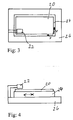
- FIGS. 3 and 4 Alternatively to the rotationally symmetrical geometry of the movable body 2 and 12 show the FIGS. 3 and 4 a schematic plan view and a side view of a Workpiece 20 in an NC machine (numerically controlled machine tool) and the Detector 22.
- the moving body in one or more Moving planes, wherein the movement of a workpiece carriage 24 with respect to a Machine base 26 in a plane x - y is shown schematically.
- the detector 22 can either directly with the workpiece 20 or with a scanning surface on the NC machine cooperate, wherein the scanning then a defined position to the workpiece 20th Has.
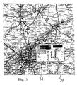
- Fig. 5 is a schematic plan view of a map 30 with a movable range finder 32 for determining distances on a map or a map with a device for detecting the relative movement between a detector and a body having a surface structure as described above Art, wherein the processor in the detector in the distance measuring a Computing function and input means 34 for inputting a number information are provided to convert the detected path to a scale that exceeds the Input means is input.
- the distance measuring device 32 also has a start-stop button 36 with which the beginning and the end of the distance measurement are entered.
- a Reference arrow 38 serves the distance measuring device 32 on the route to be measured to lead along. The measurement results can be displayed on a display 40.
- a photoelectric cell serves as a power supply of the distance measuring device 32.
Abstract
Description
Die vorliegende Erfindung bezieht sich auf ein Verfahren und eine Vorrichtung Erfassung einer Relativbewegung zwischen einem Detektor und einem Körpers mit einer Oberflächenstruktur, wobei die Relativbewegung bei ortsfestem Detektor durch eine Bewegung des Körpers, bei ortfestem Körper durch eine Bewegung des Detektors oder durch Bewegen von sowohl dem Detektor als auch des Körpers verwirklicht wird.The present invention relates to a method and an apparatus Detecting a relative movement between a detector and a body with a Surface structure, wherein the relative movement at a fixed detector by a Movement of the body, in the case of a body fixed by a movement of the detector or by moving both the detector and the body.
Bei der Bestimmung des Winkels eines sich drehenden Rotationskörpers z.B. bei Wuchtmaschinen werden im Stand der Technik Winkelkodierer eingesetzt. Der Winkelkodierer umfasst eine Lichtquelle, einen Lichtdetektor und eine Lochscheibe. Der Lichtdetektor detektiert das Licht der Lichtquelle, wobei das Licht der Lichtquelle durch die sich drehenden Lochscheibe immer wieder unterbrochen wird. Der Lichtdetektor erzeugt daraus ein Rechtecksignal. Die Impulslänge entspricht dabei der Belichtungszeit des Lichtdetektors. Ein Auswertesystem empfängt das Signal des Lichtdetektors und bestimmt daraus die Position des sich drehenden Körpers.In determining the angle of a rotating body of revolution, e.g. at Balancers are used in the prior art angle encoder. Of the Angle encoder includes a light source, a light detector and a perforated disk. Of the Light detector detects the light of the light source, wherein the light of the light source the rotating perforated disc is interrupted again and again. The light detector generates a square wave signal. The pulse length corresponds to the exposure time of the light detector. An evaluation system receives the signal of the light detector and determines from this the position of the rotating body.
Nachteilig bei diesem System ist, dass es mit einem relativ hohen Aufwand an Bauteilen, wie z.B. den Lichtdetektor, die Lichtquelle und dem Auswertesystem verbunden ist. Daraus resultiert auch eine entsprechende Komplexität und Fehleranfälligkeit des Winkelkodierers. Darüberhinaus wird das Auflösungsvermögen zur Lagebestimmung durch die Grösse, die Lage und die Anzahl der Löcher in der Lochscheibe bestimmt. Um eine höhere Auflösungsgenauigkeit bei der Lagebestimmung zu erhalten muss z. B. die Lochscheibe ausgetauscht werden. Dies ist mit einem relativ hohen Aufwand verbunden, da die Maschine, in diesem Beispiel die Wuchtmaschine, erst zerlegt werden muss.The disadvantage of this system is that it is relatively expensive Components such as e.g. the light detector, the light source and the evaluation system connected is. This results in a corresponding complexity and error rate of the Angle encoder. In addition, the resolving power becomes the orientation determined by the size, the location and the number of holes in the perforated disc. Around To obtain a higher resolution accuracy in determining the position must, for. B. the Perforated disk to be replaced. This is associated with a relatively high cost because the machine, in this example the balancing machine, first has to be disassembled.
Bei der Bestimmung des Weges eines sich bewegenden Körpers, z.B. bei der Bestimmung des Weges eines sich bewegenden Werkstücks bei NC-Maschinen, wird im Stand der Technik als Detektor ein mit der einer Antriebswelle für die Bewegung des Werkstücks gekoppelter Pulsgeber eingesetzt, ein Rechtecksignal erzeugt, das ein Maß für den zurückgelegten Weg des Werkstücks ist. Derartige Pulsgeber können die zurückgelegte Wegstrecke nur in einer Richtung bestimmen, und für eine Bestimmung eines Winkels unter dem sich das Werkstück zu der genannten Richtung bewegt, muß ein weiterer Detektor vorgesehen werden. In determining the path of a moving body, e.g. in the Determination of the path of a moving workpiece in NC machines, is in Prior art as a detector with a drive shaft for the movement of the Used workpiece coupled pulser, a square wave signal is generated, which is a measure of is the distance traveled by the workpiece. Such pulser can the determine the distance covered in one direction only, and for a determination an angle at which the workpiece moves to the said direction must be be provided further detector.
Die Aufgabe der Erfindung ist es folglich ein Verfahren und eine Vorrichtung zur Verfügung zu stellen, um einer Relativbewegung zwischen einem Detektor und einem Körpers mit einer Oberflächenstruktur zu erfassen ohne auf mechanische Mittel zurückgreifen zu müssen.The object of the invention is therefore a method and an apparatus for To provide a relative movement between a detector and a Detecting body with a surface structure without resorting to mechanical means to have to fall back.
Die oben genannte Aufgabe wird durch die unabhängigen Ansprüche der vorliegenden Erfindung gelöst. Vorteilhafte Ausgestaltungen der vorliegenden Erfindung werden in den Unteransprüchen offenbart.The above object is achieved by the independent claims of solved present invention. Advantageous embodiments of the present invention are disclosed in the subclaims.
Zur Lösung dieser Aufgabe ist das erfindungsgemäße Verfahren zur Erfassung einer Relativbewegung zwischen einem Detektor und einem Körpers mit einer Oberflächenstruktur in Form eines Weges und/oder eines Winkels der Relativbewegung dadurch gekennzeichnet, dass die Bewegung der Oberflächenstruktur des Körpers mittels einer in dem Detektor vorgesehenen Kamera erfasst wird, dass aus der Folge der erfassten Oberflächenstrukturen die Bewegungsrichtung und die Bewegungsgeschwindigkeit der Relativbewegung bestimmt wird, und dass der zurückgelegte Weg aus der Bewegungsrichtung und der Bewegungsgeschwindigkeit bestimmt wird.To solve this problem is the inventive method for detection a relative movement between a detector and a body with a Surface structure in the form of a path and / or an angle of relative movement characterized in that the movement of the surface structure of the body by means of a camera provided in the detector is detected that from the sequence of the detected Surface structures the direction of movement and the speed of movement of the Relative movement is determined, and that the distance traveled from the Movement direction and the movement speed is determined.
Eine vorteilhafte Ausgestaltung des erfindungsgemäßen Verfahrens, wobei der sich bewegende Körper ein rotationssymmetrischer, sich drehender Körper und der Detektor ortsfest angeordnet ist, ist dadurch gekennzeichnet, dass die Oberflächenstruktur an einer an dem sich drehenden Körper vorgesehenen Abtastfläche erfasst wird, und dass der aus der Bewegungsrichtung und der Bewegungsgeschwindigkeit bestimmte, zurückgelegte Weg in einen zurückgelegten Winkel umgerechnet wird.An advantageous embodiment of the method according to the invention, wherein the moving bodies a rotationally symmetric, rotating body and the detector is arranged stationary, characterized in that the surface structure at a is detected on the rotating body provided scanning surface, and that of the direction of movement and the speed of movement certain, traveled Path is converted into a covered angle.
Eine vorteilhafte Ausgestaltung des erfindungsgemäßen Verfahrens ist dadurch gekennzeichnet, dass der zurückgelegte Weg in eine definierte Anzahl von Inkrementen, beispielsweise 360 Inkremente, aufgeteilt wird. Mit dieser Inkrementierung ist eine direkte Umrechnung in die Winkeleinheit Grad möglich. Eine Umrechnung in jede andere geeignete Winkeleinheit ist darüberhinaus ebenfalls möglich.An advantageous embodiment of the method according to the invention is characterized characterized in that the distance traveled in a defined number of increments, for example, 360 increments, is divided. With this incrementing is a direct Conversion into the angular unit degrees possible. A conversion into each other suitable angle unit is also possible.
Eine vorteilhafte Ausgestaltung des erfindungsgemäßen Verfahrens, wobei der sich bewegende Körper ein sich in einer Ebene gewegender Körper und der Detektor ortsfest angeordnet ist, ist dadurch gekennzeichnet, dass die Oberflächenstruktur an einer an dem sich drehenden Körper vorgesehenen Abtastfläche erfasst wird, und dass aus der Bewegungsrichtung und der Bewegungsgeschwindigkeit der zurückgelegte Weg des Körpers bestimmt wird.An advantageous embodiment of the method according to the invention, wherein the moving bodies are a body moving in a plane and the detector is stationary is arranged, is characterized in that the surface structure at one of the rotating body provided scanning surface is detected, and that from the Direction of movement and the speed of movement of the path traveled Body is determined.
Eine vorteilhafte Ausgestaltung des erfindungsgemäßen Verfahrens, wobei der
Körper ortsfest angeordnet ist und der Detektor relativ zu dem Körper bewegt wird, ist
dadurch gekennzeichnet, dass die Oberflächenstruktur an einer an dem Körper
vorgesehenen Abtastfläche erfasst wird, und dass aus der Bewegungsrichtung und der
Bewegungsgeschwindigkeit der Relativbewegung die zurückgelegte Wegstrecke bestimmt
wird.An advantageous embodiment of the method according to the invention, wherein the body is arranged stationary and the detector is moved relative to the body, is
characterized in that the surface structure is detected on a scanning surface provided on the body, and that the distance traveled is determined from the direction of movement and the speed of movement of the relative movement.
Eine vorteilhafte Ausgestaltung des erfindungsgemäßen Verfahrens ist dadurch gekennzeichnet, dass eine Referenzmarke in vorgegebener Relation zu dem Körper vorgesehen wird.An advantageous embodiment of the method according to the invention is characterized characterized in that a reference mark in a predetermined relation to the body is provided.
Zur Lösung dieser Aufgabe ist die erfindungsgemäße Vorrichtung zur Erfassung einer Relativbewegung zwischen einem Detektor und einem Körpers mit einer Oberflächenstruktur in Form eines Weges und/oder eines Winkels der Relativbewegung gekennzeichnet durch eine in dem Detektor vorgesehene Kamera, die die Bewegung der Oberflächenstruktur des Körpers erfasst, und durch eine Prozessoreinrichtung, die aus der Folge der erfassten Oberflächenstrukturen die Bewegungsrichtung und die Bewegungsgeschwindigkeit der Relativbewegung und daraus dem zurückgelegte Weg der Relativbewegung bestimmt.To solve this problem, the inventive device for detecting a relative movement between a detector and a body with a Surface structure in the form of a path and / or an angle of relative movement characterized by a camera provided in the detector which controls the movement of the camera Surface structure of the body detected, and by a processor device, made of the Sequence of the detected surface structures the direction of movement and the Movement speed of the relative movement and from this the distance covered by the Relative movement determined.
Eine vorteilhafte Ausgestaltung der erfindungsgemäßen Vorrichtung, wobei der sich bewegende Körper ein rotationssymmetrischer, sich drehender Körper und der Detektor ortsfest angeordnet ist, ist dadurch gekennzeichnet, dass die Kamera ausgestaltet ist, um die Oberflächenstruktur an einer an dem sich drehenden Körper vorgesehenen Abtastfläche zu erfassen, und dass der Prozessor ausgestaltet ist, um aus der Bewegungsrichtung und der Bewegungsgeschwindigkeit den zurückgelegten Weg zu bestimmen und ihn in einen zurückgelegten Winkel umzurechnen.An advantageous embodiment of the device according to the invention, wherein the moving bodies a rotationally symmetric, rotating body and the Detector is stationary, is characterized in that the camera designed is to provide the surface structure at one of the rotating body Scanning area to capture, and that the processor is designed to be out of the Direction of movement and the speed of movement the path covered determine and convert it into a traversed angle.
Eine vorteilhafte Ausgestaltung der erfindungsgemäßen Vorrichtung, wobei der sich bewegende Körper ein sich in einer Ebene gewegender Körper und der Detektor ortsfest angeordnet ist, ist dadurch gekennzeichnet, dass die Kamera ausgestaltet ist, um die Oberflächenstruktur an einer an dem sich drehenden Körper vorgesehenen Abtastfläche zu erfassen, und der Prozessor ausgestaltet ist, um aus der Bewegungsrichtung und der Bewegungsgeschwindigkeit der zurückgelegte Weg des Körpers zu bestimmen.An advantageous embodiment of the device according to the invention, wherein the moving bodies are a body moving in a plane and the detector is stationary, is characterized in that the camera is designed to the surface structure on a provided on the rotating body scanning surface to capture, and the processor is configured to move from the direction of movement and the Movement speed to determine the distance traveled by the body.
Eine vorteilhafte Ausgestaltung der erfindungsgemäßen Vorrichtung, wobei der Körper ortsfest angeordnet ist und der Detektor relativ zu dem Körper bewegt wird, ist dadurch gekennzeichnet, dass die Oberflächenstruktur an einer an dem Körper vorgesehenen Abtastfläche erfasst wird, und dass der Prozessor ausgestaltet ist, um der Bewegungsrichtung und der Bewegungsgeschwindigkeit der Relativbewegung die zurückgelegte Wegstrecke zu bestimmen. An advantageous embodiment of the device according to the invention, wherein the Body is stationary and the detector is moved relative to the body is characterized in that the surface structure on one of the body provided scanning surface is detected, and that the processor is configured to the Direction of movement and the speed of movement of the relative movement determine the distance traveled.
Eine vorteilhafte Ausgestaltung der erfindungsgemäßen Vorrichtung ist dadurch gekennzeichnet, dass das Referenzmerkmal eine Markierung oder eine charakteristische Struktur ist.An advantageous embodiment of the device according to the invention is characterized characterized in that the reference feature is a mark or a characteristic Structure is.
Eine vorteilhafte Ausgestaltung der erfindungsgemäßen Vorrichtung ist dadurch gekennzeichnet, dass das Referenzmerkmal eine Kerbe oder ein Strich ist.An advantageous embodiment of the device according to the invention is characterized characterized in that the reference feature is a notch or a dash.
Eine vorteilhafte Ausgestaltung der erfindungsgemäßen Vorrichtung ist dadurch gekennzeichnet, dass das Referenzmerkmal eine separate die Refenrenzmarke ist, und dass ein separater Sensor zum Erfassen des Referenzmerkmals vorgesehen ist.An advantageous embodiment of the device according to the invention is characterized characterized in that the reference feature is a separate the reference mark, and that a separate sensor for detecting the reference feature is provided.
Eine vorteilhafte Ausgestaltung der erfindungsgemäßen Vorrichtung ist dadurch gekennzeichnet, dass der Sensor eine Fotodiode ist. Durch eine Fotodiode lassen sich zur Erfassung der Referenzmarke die Produktionskosten der Vorrichtung der vorliegenden Erfindung deutlich verringern.An advantageous embodiment of the device according to the invention is characterized characterized in that the sensor is a photodiode. Through a photodiode can be to Detection of the reference mark the production cost of the device of the present Significantly reduce the invention.
Eine vorteilhafte Ausgestaltung der erfindungsgemäßen Vorrichtung ist gekennzeichnet durch eine Lichtquelle in dem Detektor, mit der die Oberflächenstruktur des Körper angestrahlt wird.An advantageous embodiment of the device according to the invention is characterized by a light source in the detector, with which the surface structure the body is illuminated.
Eine vorteilhafte Ausgestaltung der erfindungsgemäßen Vorrichtung ist dadurch gekennzeichnet, dass die Lichtquelle eine Licht emittierende Diode (LED) ist. Durch die Verwendung einer LED kann die Baugrösse und der Energieverbrauch der Vorrichtung reduzieren, was einer Miniaturisierung der Vorrichtung zu gute kommt.An advantageous embodiment of the device according to the invention is characterized characterized in that the light source is a light-emitting diode (LED). By the Using an LED can reduce the size and power consumption of the device reduce what comes to miniaturization of the device to good.
Eine vorteilhafte Ausgestaltung der erfindungsgemäßen Vorrichtung ist dadurch gekennzeichnet, dass die Kamera ein Kamerachip ist. Ein Kamerachip bietet den Vorteil der detailgenauen Bilderfassung mit einer hohen Abtastrate. Damit lässt sich eine hohe Auflösung bei der Bestimmung des Wegs oder des Winkels erreichen.An advantageous embodiment of the device according to the invention is characterized characterized in that the camera is a camera chip. A camera chip offers the advantage the detailed image capture with a high sampling rate. This can be a high Achieve resolution in determining the path or angle.
Eine vorteilhafte Ausgestaltung der erfindungsgemäßen Vorrichtung ist dadurch gekennzeichnet, dass der Kamerachip und der Prozessor auf einem Chip integriert sind.An advantageous embodiment of the device according to the invention is characterized characterized in that the camera chip and the processor are integrated on a chip.
Die Erfindung betrifft ferner eine Wuchtmaschine mit einer Vorrichtung zum Erfassen der Relativbewegung zwischen einem Detektor und einem Körpers mit einer Oberflächenstruktur der oben beschriebenen Art, wobei die Winkellage eines zu wuchtenden Rotors bestimmt wird.The invention further relates to a balancing machine with a device for Detecting the relative movement between a detector and a body with a Surface structure of the type described above, wherein the angular position of a balancing rotor is determined.
Die Erfindung betrifft ferner eine NC-Maschine mit einer Vorrichtung zum Erfassen der Relativbewegung zwischen einem Detektor und einem Körpers mit einer Oberflächenstruktur der oben beschriebenen Art, wobei die Wegstrecke eines in der NC-Maschine zu bewegenden Werkstücks bestimmt wird. The invention further relates to an NC machine with a device for Detecting the relative movement between a detector and a body with a Surface structure of the type described above, wherein the distance of one in the NC machine is determined to moving workpiece.
Die Erfindung betrifft ferner ein Entfernungsmeßgerät zur Bestimmung von Entfernungen auf einem Plan oder einer Landkarte mit einer Vorrichtung zum Erfassen der Relativbewegung zwischen einem Detektor und einem Körpers mit einer Oberflächenstruktur der oben beschriebenen Art, wobei der Prozessor eine Rechenfunktion aufweist und Eingabemittel zum Eingeben einer Zahleninformation vorgesehen sind, um den erfassten Weg nach einem Maßstab umzurechnen, der über die Eingabemittel einzugeben ist.The invention further relates to a distance measuring device for the determination of Distances on a map or map with a device for capturing the Relative movement between a detector and a body with a Surface structure of the type described above, wherein the processor has a computing function and input means for inputting a number information are provided to to convert the recorded path to a scale via the input means is to enter.
Ausführungsbeispiele der Erfindung werden nun anhand der zeichnungen
beschrieben. Es zeigen:
Figur 1 zeigt den prinzipiellen Aufbau der Vorrichtung der vorliegenden Erfindung
am Beispiel eines rotationsymmetrischen Körpers 2 in Schnittansicht. An dem Körper 2 ist
ein Detektor 5 angeordnet, der eine Lichtquelle 4, zum Beispiel eine lichtemittierende
Diode, und eine Kamera 6, zum Beispiel ein Kamerachip, aufweist. Der Detektor 5 erfasst
kontinuierlich die Oberflächenstruktur des Körpers 2.Figure 1 shows the basic structure of the device of the present invention
the example of a rotationally
Zur Verarbeitung der Daten der erfassten Oberflächenstruktur ist die Kamera 6 mit
einem Prozessor verbunden. Auf dem Prozessor befindet sich ein Programm, das aus der
Folge der erfassten Oberflächenstruktur die Bewegungsrichtung und die Geschwindigkeit
des sich bewegenden Körpers 2 berechnet und als Ergebnis die Koordinaten des sich
bewegenden Körpers 2 bestimmt, die aus der Relativbewegung folgen. Des weiteren
befindet sich im axialen Ende des Körpers 2 eine Referenzmarke 8, deren Aufgabe und
Funktion in Figur 2 näher beschrieben wird.For processing the data of the detected surface structure, the camera 6 with
connected to a processor. There is a program on the processor that comes from the
As a result of the detected surface structure, the direction of movement and the speed
of the moving
Figur 2 zeigt eine Seitenansicht eines rotationssymmetrischen Körpers 12, an dem
eine Referenzmarke 14 und ein Sensor 16 zum Erfassen der der Referenzmarke 14
vorgesehen ist. Bei einer Drehung des Körpers 12 wird die Referenzmarke 14, die in Figur
2 am Körper 12 radial angebracht ist, von dem Sensor 16 erfasst. Mit dem Fixieren der
Referenzmarke 14 am rotationssymmetrischen Körper 12 wird die zu erfassende
Wegstrecke, in diesem Fall der Umfang des rotationssymmetrischen Körpers 12, mit einem
Anfangs- und Endpunkt in Form der Referenzmarke 14 definiert.FIG. 2 shows a side view of a rotationally
Somit lässt sich bei einem rotationssymmetrischen Körper mit der Vorrichtung und
dem Verfahren der vorliegenden Erfindung eine relative Winkelposition des sich
bewegenden Körpers bestimmen. Bei der Bestimmung eines Drehwinkels wird die mit
dem Lichtsensor 6 aus Figur 1 erfasste und durch die Referenzmarke 8 bzw. 14 markierte
Wegstrecke in eine definierte Anzahl von Inkrementen aufgeteilt. Die erfasste Wegstrecke
kann dabei in 360 Inkremente aufgeteilt werden, was dem Gradsystem mit 360 Grad für
den Vollkreis entspricht. Neben der Aufteilung in 360 Inkremente sind alle anderen
geeigneten Inkrementierungen möglich.Thus can be in a rotationally symmetrical body with the device and
the method of the present invention, a relative angular position of
determine the moving body. When determining a rotation angle with the
the light sensor 6 of Figure 1 detected and marked by the
Für die Anwendung bei Wuchtmaschinen dient die Inkrementierung dazu, die Position für eine Unwuchtkompensation beim manuellen oder automatischen Eindrehen von rotationssymmetrischen Körpern zum Ausgleich der Unwucht zu bestimmen. Zum Beispiel können bei einem Elektroanker die Anzahl der Pole (Stege) mit einem Kamerachip erfasst und für die Unwuchtkorrektur am jeweiligen Pol eingedreht werden. Bei Lüftern kann zum Beispiel die Anzahl der Flügel bzw. der Radiatorflügel erfasst und für die Unwuchtkorrektur am jeweiligen Flügel (Komponente) eingedreht werden.For the application in balancing machines, the increment serves to, the Position for unbalance compensation during manual or automatic screwing of rotationally symmetrical bodies to compensate for the unbalance. To the For example, for an electric armature, the number of poles (bars) with a Camera chip detected and screwed for the correction of imbalance at each pole. For fans, for example, the number of wings or the radiator wings detected and for the imbalance correction on the respective wing (component) are screwed.
Alternativ zur rotationssymmetrischen Geometrie des beweglichen Körpers 2 bzw.
12 zeigen die Fign. 3 und 4 eine schematische Draufsicht bzw. eine Seitenansicht eines
Werkstücks 20 in einer NC-Maschine (numerisch gesteuerten Werkzeugmaschine) und den
Detektor 22. In diesem Fall kann der sich bewegende Körper in einer oder mehreren
Ebenen bewegen, wobei die Bewegung eines Werkstückschlittens 24 gegenüber einer
Maschinenbasis 26 in einer Ebene x - y schematisch dargestellt ist. Der Detektor 22 kann
entweder direkt mit dem Werkstück 20 oder mit einer Abtastfläche an der NC-Maschine
zusammenwirken, wobei die Abtastfläche dann eine definierte Lage zu dem Werkstück 20
hat.Alternatively to the rotationally symmetrical geometry of the
Fig. 5 ist eine schematische Draufsicht auf eine Landkarte 30 mit einem
beweglichen Entfernungsmeßgerät 32 zur Bestimmung von Entfernungen auf einem Plan
oder einer Landkarte mit einer Vorrichtung zum Erfassen der Relativbewegung zwischen
einem Detektor und einem Körpers mit einer Oberflächenstruktur der oben beschriebenen
Art, wobei der Prozessor in dem Detektor in dem Entfernungsmeßgerät eine
Rechenfunktion aufweist und Eingabemittel 34 zum Eingeben einer Zahleninformation
vorgesehen sind, um den erfassten Weg nach einem Maßstab umzurechnen, der über die
Eingabemittel einzugeben ist. Das Entfernungsmeßgerät 32 hat ferner eine Start-StopTaste
36, mit der der Beginn und das Ende der Entfernungsmessung eingegeben wird. Eine
Refenrenzpfeil 38 dient dazu, das Entfernungsmeßgerät 32 an der zu vermessenden Strecke
entlang zu führen. Die Meßergebnisse können auf einem Display 40 angezeigt werden.
Eine photoelektrische Zelle dient als Stromversorgung des Entfernungsmeßgeräts 32.Fig. 5 is a schematic plan view of a
Claims (24)
Applications Claiming Priority (2)
| Application Number | Priority Date | Filing Date | Title |
|---|---|---|---|
| DE102004014994 | 2004-03-26 | ||
| DE200410014994 DE102004014994A1 (en) | 2004-03-26 | 2004-03-26 | Method and device for detecting a relative movement between a detector and a body having a surface structure |
Publications (2)
| Publication Number | Publication Date |
|---|---|
| EP1580535A2 true EP1580535A2 (en) | 2005-09-28 |
| EP1580535A3 EP1580535A3 (en) | 2006-10-18 |
Family
ID=34854076
Family Applications (1)
| Application Number | Title | Priority Date | Filing Date |
|---|---|---|---|
| EP05006650A Withdrawn EP1580535A3 (en) | 2004-03-26 | 2005-03-24 | Method and apparatus for detecting a relative displacement between a detector and a body with surface structure |
Country Status (2)
| Country | Link |
|---|---|
| EP (1) | EP1580535A3 (en) |
| DE (1) | DE102004014994A1 (en) |
Families Citing this family (1)
| Publication number | Priority date | Publication date | Assignee | Title |
|---|---|---|---|---|
| DE102006030810B4 (en) * | 2006-06-30 | 2010-06-10 | Siemens Ag | Arrangement for detecting the movement of flat items |
Citations (3)
| Publication number | Priority date | Publication date | Assignee | Title |
|---|---|---|---|---|
| US4891767A (en) * | 1988-06-02 | 1990-01-02 | Combustion Engineering, Inc. | Machine vision system for position sensing |
| US5644139A (en) * | 1995-03-02 | 1997-07-01 | Allen; Ross R. | Navigation technique for detecting movement of navigation sensors relative to an object |
| EP1037020A2 (en) * | 1999-03-08 | 2000-09-20 | Hewlett-Packard Company | Optical motion detection |
-
2004
- 2004-03-26 DE DE200410014994 patent/DE102004014994A1/en not_active Withdrawn
-
2005
- 2005-03-24 EP EP05006650A patent/EP1580535A3/en not_active Withdrawn
Patent Citations (3)
| Publication number | Priority date | Publication date | Assignee | Title |
|---|---|---|---|---|
| US4891767A (en) * | 1988-06-02 | 1990-01-02 | Combustion Engineering, Inc. | Machine vision system for position sensing |
| US5644139A (en) * | 1995-03-02 | 1997-07-01 | Allen; Ross R. | Navigation technique for detecting movement of navigation sensors relative to an object |
| EP1037020A2 (en) * | 1999-03-08 | 2000-09-20 | Hewlett-Packard Company | Optical motion detection |
Also Published As
| Publication number | Publication date |
|---|---|
| DE102004014994A1 (en) | 2005-10-13 |
| EP1580535A3 (en) | 2006-10-18 |
Similar Documents
| Publication | Publication Date | Title |
|---|---|---|
| EP3278302B1 (en) | Motion-measuring system of a machine and method for operating the motion-measuring system | |
| DE69925582T2 (en) | DEVICE AND METHOD FOR OPTICALLY MEASURING THE SURFACE CONTOUR OF AN OBJECT | |
| DE3016361A1 (en) | METHOD AND DEVICE FOR ELECTRO-OPTICALLY DETERMINING THE DIMENSIONS, POSITION OR POSITION OF AN OBJECT | |
| CN106768399A (en) | Rectangular laser spot energy distribution rapid detection system and method | |
| WO2012079734A1 (en) | Setting and/or measurement apparatus | |
| DE19828498C2 (en) | Method for measuring unbalance of rotating bodies and device for carrying out the method | |
| DE2907648C2 (en) | ||
| DE4116313C2 (en) | Method and device for measuring the elastomechanics of sediments from suspensions and emulsions | |
| EP0094481B1 (en) | Opto-electrical measuring-device | |
| DE10135960B4 (en) | Absolute position detection device for a linear actuator | |
| DE3534193A1 (en) | EDGE DETECTING DEVICE IN AN OPTICAL MEASURING INSTRUMENT | |
| EP3760981B1 (en) | Angle measuring device and method for operating an angle measuring device | |
| EP1580535A2 (en) | Method and apparatus for detecting a relative displacement between a detector and a body with surface structure | |
| DE102006015627B4 (en) | Method and device for determining and measuring shape deviations and undulations on rotationally symmetrical parts | |
| DE3417016C1 (en) | Method for determining the position and speed of objects | |
| EP0514726B1 (en) | Method for making allowance for deviation of the crank pin position of a crankshaft during balancing and device therefor | |
| DE102010001833A1 (en) | Form measuring device, shape measuring method and program | |
| CN207881736U (en) | A kind of encoder test platform | |
| DE3242984C2 (en) | Tester for dial gauges | |
| DD255583A1 (en) | METHOD AND DEVICE FOR AUTOMATED TESTING OF THE DISPLAY DEVIATION OF BALANCING SCREWS | |
| DE10146713A1 (en) | Method for measuring large components, in particular car bodies of rail vehicles | |
| DE10005852A1 (en) | Method and device for producing height images of technical surfaces in microscopic resolution | |
| DD228050A1 (en) | METHOD AND DEVICE FOR ACCURATELY COLLECTING DIVISIONS | |
| DD265684A1 (en) | AUTOMATIC OPTOELECTRONIC SCREENING DEVICE | |
| DD236379A1 (en) | EVALUATION DEVICE OF A POWDER IMAGING WITH THE HELP OF COHERENT LIGHT |
Legal Events
| Date | Code | Title | Description |
|---|---|---|---|
| PUAI | Public reference made under article 153(3) epc to a published international application that has entered the european phase |
Free format text: ORIGINAL CODE: 0009012 |
|
| AK | Designated contracting states |
Kind code of ref document: A2 Designated state(s): AT BE BG CH CY CZ DE DK EE ES FI FR GB GR HU IE IS IT LI LT LU MC NL PL PT RO SE SI SK TR |
|
| AX | Request for extension of the european patent |
Extension state: AL BA HR LV MK YU |
|
| PUAL | Search report despatched |
Free format text: ORIGINAL CODE: 0009013 |
|
| AK | Designated contracting states |
Kind code of ref document: A3 Designated state(s): AT BE BG CH CY CZ DE DK EE ES FI FR GB GR HU IE IS IT LI LT LU MC NL PL PT RO SE SI SK TR |
|
| AX | Request for extension of the european patent |
Extension state: AL BA HR LV MK YU |
|
| AKX | Designation fees paid | ||
| STAA | Information on the status of an ep patent application or granted ep patent |
Free format text: STATUS: THE APPLICATION IS DEEMED TO BE WITHDRAWN |
|
| 18D | Application deemed to be withdrawn |
Effective date: 20070419 |
|
| REG | Reference to a national code |
Ref country code: DE Ref legal event code: 8566 |