EP1582164A1 - Intramedullary nail comprising a stem whereon longitudinal portions are provided driving elements of shape-memory material - Google Patents
Intramedullary nail comprising a stem whereon longitudinal portions are provided driving elements of shape-memory material Download PDFInfo
- Publication number
- EP1582164A1 EP1582164A1 EP04007790A EP04007790A EP1582164A1 EP 1582164 A1 EP1582164 A1 EP 1582164A1 EP 04007790 A EP04007790 A EP 04007790A EP 04007790 A EP04007790 A EP 04007790A EP 1582164 A1 EP1582164 A1 EP 1582164A1
- Authority
- EP
- European Patent Office
- Prior art keywords
- intramedullary nail
- stem
- nail
- longitudinal portions
- shape
- Prior art date
- Legal status (The legal status is an assumption and is not a legal conclusion. Google has not performed a legal analysis and makes no representation as to the accuracy of the status listed.)
- Withdrawn
Links
Images


Classifications
-
- A—HUMAN NECESSITIES
- A61—MEDICAL OR VETERINARY SCIENCE; HYGIENE
- A61B—DIAGNOSIS; SURGERY; IDENTIFICATION
- A61B17/00—Surgical instruments, devices or methods, e.g. tourniquets
- A61B17/56—Surgical instruments or methods for treatment of bones or joints; Devices specially adapted therefor
- A61B17/58—Surgical instruments or methods for treatment of bones or joints; Devices specially adapted therefor for osteosynthesis, e.g. bone plates, screws, setting implements or the like
- A61B17/68—Internal fixation devices, including fasteners and spinal fixators, even if a part thereof projects from the skin
- A61B17/72—Intramedullary pins, nails or other devices
- A61B17/7233—Intramedullary pins, nails or other devices with special means of locking the nail to the bone
- A61B17/7258—Intramedullary pins, nails or other devices with special means of locking the nail to the bone with laterally expanding parts, e.g. for gripping the bone
- A61B17/7275—Intramedullary pins, nails or other devices with special means of locking the nail to the bone with laterally expanding parts, e.g. for gripping the bone with expanding cylindrical parts
-
- A—HUMAN NECESSITIES
- A61—MEDICAL OR VETERINARY SCIENCE; HYGIENE
- A61B—DIAGNOSIS; SURGERY; IDENTIFICATION
- A61B17/00—Surgical instruments, devices or methods, e.g. tourniquets
- A61B17/56—Surgical instruments or methods for treatment of bones or joints; Devices specially adapted therefor
- A61B17/58—Surgical instruments or methods for treatment of bones or joints; Devices specially adapted therefor for osteosynthesis, e.g. bone plates, screws, setting implements or the like
- A61B17/68—Internal fixation devices, including fasteners and spinal fixators, even if a part thereof projects from the skin
- A61B17/72—Intramedullary pins, nails or other devices
- A61B17/7233—Intramedullary pins, nails or other devices with special means of locking the nail to the bone
- A61B17/7258—Intramedullary pins, nails or other devices with special means of locking the nail to the bone with laterally expanding parts, e.g. for gripping the bone
- A61B17/7266—Intramedullary pins, nails or other devices with special means of locking the nail to the bone with laterally expanding parts, e.g. for gripping the bone with fingers moving radially outwardly
-
- A—HUMAN NECESSITIES
- A61—MEDICAL OR VETERINARY SCIENCE; HYGIENE
- A61B—DIAGNOSIS; SURGERY; IDENTIFICATION
- A61B17/00—Surgical instruments, devices or methods, e.g. tourniquets
- A61B2017/00831—Material properties
- A61B2017/00867—Material properties shape memory effect
Definitions
- the present invention relates in its more general aspect to an intramedullary nail suitable for insertion in a fractured elongate bone and an application method of said nail in said bone.
- the invention relates to an intramedullary nail suitable for insertion in a fractured elongate bone, such as a femur or a tibia, comprising a substantially straight stem, having a predetermined axis, extending between a proximal end and a distal end.
- Intramedullary nails are known, which, during a surgical operation, are inserted in a fractured elongate bone and fixed therein, in order to reconstruct the original bone configuration and meanwhile recover the bone solidity, so that callus regeneration mechanisms can correctly occur.
- the stems of these intramedullary nails are generally cylinder-shaped and they can be both solid and hollow.
- two offset holes are usually provided on the nail, having axes lying on parallel planes and extending diametrically across the stem, in correspondence with the nail distal end, and two offset holes having the same size, having axes not necessarily lying on parallel planes, in correspondence with the nail proximal end.
- Said holes are suitable for housing bone screws, which are inserted, after a convenient bone drilling, in the bone, with the subsequent fixation of the intramedullary nail to the bone portions.
- intramedullary nails being structured as above schematically described have known drawbacks mainly underlined when bone drillings are to be performed for bone screw insertion. This step is particularly critical since it is known that a good nail fastening essentially depends on the correct realisation of these bone drillings, obviously made in correspondence with the holes of the inserted intramedullary nail.
- the precise location of the intramedullary nail holes is made difficult by the fact that the holes are no more visible, being the nail inserted in the bone. It is then worth underlining a further location problem, i.e. the fact that the intramedullary nail can be, when being inserted, slightly bent, so that the holes at the nail distal end are no more, with respect to the proximal end, in the same position as before installing the nail.
- the problem underlying the present invention is to provide an intramedullary nail suitable for insertion in a fractured elongate bone, capable to meet the above-mentioned requirement, meanwhile overcoming, in a simple and effective way, all the drawbacks mentioned with reference to the prior art.
- an intramedullary nail suitable for insertion in a fractured elongate bone as above described and characterised in that it comprises expansion means for the nail fixation to the bone, said expansion means being operable by at least one driving element realised with a shape-memory material.
- an intramedullary nail according to the present invention is shown in a first embodiment and in three further alternative embodiments.
- the nail in the embodiment described at first, is globally indicated with 10, while in the alternative embodiments the nail of the invention is indicated with 110, 210 and 310 respectively. It is specified that, in these alternative embodiments, the elements being structurally or functionally similar to the elements of the nail 10 are indicated with the same reference number and the detailed description thereof is not repeated for short.
- the nail 10 shown in figures 1, 2 and 3, which is suitable for insertion in a fractured elongate bone 12, such as for example a femur or a tibia, comprises a substantially straight stem 14, having a predetermined axis X-X, extending between a proximal end 16 and a distal end 18.
- the nail 10 comprises expansion means 20 for the nail fixation to the bone, said expansion means 20 being operable by at least one driving element 22 realised with a shape-memory material.
- Shape memory material means a material having a given initial starting shape and taking, under predetermined external conditions (for example a temperature rise and/or drop) or undergoing a predetermined activation condition, i.e. after a so-called “material instruction” step, a given new shape.
- shape-memory materials suitable for use in the present invention are, for instance, certain nickel-titanium alloys.
- the invention is based on the following principle: subjecting an element realised in a shape memory material, having a predetermined initial shape at rest, to said so-called “material instruction” step (for example to a predetermined temperature variation), said element takes a shape being maintained as long as the "instruction” step effect persists; said shape, being different from the initial shape, can be called transient shape and it is temporary or unstable.
- the "instruction” step effect stops, the element leaves said transient shape and, coming back towards the initial shape, takes a working shape.
- said material can arrive at the initial shape or it can go further on the initial shape, arriving at a final shape. It is worth pointing out that the more this final shape is far from the initial shape, the more the available shape memory energy of the material is high.
- the invention has been reached as result of the intuition that an element realised in a shape memory material, in the passage from the transient shape towards the working shape, can create the fixing of the intramedullary nail in the bone.
- the stem 14 comprises a plurality of longitudinal portions 24 forming, close to each other, a cylindrical tubular body.
- the longitudinal portions 24 have a circular-crown-sector-shaped section.
- the longitudinal portions 24 are four and the angle at the circular crown sector centre is a right angle.
- Expansion means 20 shape in said longitudinal portions 24, which can be radially spaced apart from the axis X-X of the stem 14.
- the cross section of the cylindrical body 26 can be, for example, circular or square.
- the cylindrical body 26 is fixed, at the two opposite ends, to two longitudinal portions 24, generally in correspondence with surfaces being turned towards the axis X-X.
- recesses 28, being accessible from the axis X-X, are provided in said longitudinal portions 24.
- Said recesses 28 of the longitudinal portions 24 are conjugate to each other: in other words, when the longitudinal portions 24 are close to each other, said recesses 28 define an area 30 comprising said bent cylindrical body 26 which is connected, at two opposite ends, to the two longitudinal portions 24 being concerned.
- each end 16 and 18 of the stem 14 are provided in correspondence with each end 16 and 18 of the stem 14.
- the four cylindrical bodies 26 of each end 16 and 18 are symmetrically positioned with respect to the axis X-X, generally at a same height with respect to the axis X-X.
- the nail 110 according to the invention is shown, wherein at least one driving element 22, shaping in a X-shaped structure 126, is provided between the longitudinal portions 24.
- the structure 126 has thus four ends 126a, 126b, 126c and 126d: in correspondence with two first adjacent ends 126a and 126b, the structure 126 is fixed to two longitudinal portions 24, generally in correspondence with surfaces being turned towards the axis X-X.
- the fixation is performed for example through buckling with plastic deformation.
- grooves 128, being accessible from the axis X-X, are provided in said longitudinal portions 24.
- Said grooves 128 of the longitudinal portions 24 are conjugate to each other: in other words, when the longitudinal portions 24 are close to each other, said grooves 128 define an area 130 comprising said structure 126 when being bent, i.e. when the two first adjacent ends 126a and 126b are close to each other and when also the two remaining adjacent ends 126c and 126d are close to each other.
- the two remaining ends 126c and 126d are slideble in said grooves 128.
- the longitudinal portions 24 are four and four structures 126 are provided in correspondence with each end 16 and 18 of the stem 14.
- the four structures 126 of each end 16 and 18 are symmetrically positioned with respect to the axis X-X, generally at a same height with respect to the axis X-X.
- the X-shaped structures 126 can be alternatively obtained by joining pairs of V-or-U-bent cylindrical bodies 26, in correspondence with the bent area. It is evident that in this case, in order to achieve the same effect as structures 126, the cylindrical bodies 26 will be so instructed as to be bent in the final shape and to be substantially straight in the initial shape.
- the nail 210 according to the invention is shown, which is similar to the nail 10 and it has thus V-or-U-bent cylindrical bodies 26.
- the adjacent cylindrical bodies 26 are positioned with the bend arranged on opposite sides: in other words, in the case of four longitudinal portions 24 with four cylindrical bodies 26, the cylindrical bodies 26, which face to each other, are specular.
- the nail 310 according to the invention is shown, wherein expansion means 20 shape in a rod 332, two opposite ends 334 and 336 of said rod 332 being spaceable in a substantially radial way from the axis X-X of the stem 14.
- the rod 332 is hinged, in an intermediate position thereof, on the stem 14 by means of a pin 338.
- the rod 332 is hinged in an intermediate position of the stem 14.
- the rod 332 is rectangle-shaped and substantially as long as the stem 14.
- the rod 332 is also equipped with a groove 340, in correspondence with the area wherein the pin 338 is positioned.
- a torsion spring 342 realised with a shape-memory material is positioned around the pin 338: this is the driving element 22 of the nail 310.
- An end of the spring 342 is constrained to the stem 14, while the opposite end is positioned in front of a wall of the groove 340, or preferably it is connected thereto.
- the spring 342 is expanded, with an increase in the angle between the two ends of the spring 342 causing, through the thrust of the opposite end of the spring 342 on the wall of the groove 340, a rotation of the rod 332.
- the rod 332 is preferably equipped, at the two ends 334 and 336, with sharp portions for an improved fixation of the nail 310.
- An application method of an intramedullary nail according to the present invention in said fractured elongate bone 12 comprises:
- the nail according to the invention is positioned in said elongate bone 12, in the initial shape thereof.
- said driving element 22 realised with a shape-memory material is operated.
- the longitudinal portions 24 radially space apart up to realise an interference with the medullary canal surfaces surrounding the longitudinal portions 24.
- the ends 334 and 336 of the rod 332 space apart in a substantially radial way from the axis X-X of the stem 14.
- the main advantage achieved by the intramedullary nail suitable for insertion in a fractured elongate bone, as well as by the application method of said nail in said fractured bone, according to the present invention, is the fact of unusually simplifying the fixation step of the intramedullary nail inserted in the fractured bone.
- the nail fixation is obtained simultaneously with the insertion thereof in the bone, since the shape-memory elements, cooled at first to take the initial shape, take in the bone their final shape, due to the heat released by the patient's body.
- Another advantage of the intramedullary nail according to the present invention is to prevent undesired nail torsions or rotations in the bone during the application step.
Abstract
An intramedullary nail (10, 110, 210, 310) suitable for insertion in a fractured elongate bone (12) and for an unusually simple fixation therein comprises a substantially straight stem (14), having a predetermined axis (X-X), extending between a proximal end (16) and a distal end (18) and expansion means (20) for the nail fixation to the bone, said expansion means (20) being operable by at least one driving element (22) realised with a shape-memory material.
Description
- The present invention relates in its more general aspect to an intramedullary nail suitable for insertion in a fractured elongate bone and an application method of said nail in said bone.
- In particular, the invention relates to an intramedullary nail suitable for insertion in a fractured elongate bone, such as a femur or a tibia, comprising a substantially straight stem, having a predetermined axis, extending between a proximal end and a distal end.
- Intramedullary nails are known, which, during a surgical operation, are inserted in a fractured elongate bone and fixed therein, in order to reconstruct the original bone configuration and meanwhile recover the bone solidity, so that callus regeneration mechanisms can correctly occur.
- The stems of these intramedullary nails are generally cylinder-shaped and they can be both solid and hollow.
- In order to fix the intramedullary nail to the bone portions to be reconstructed, two offset holes are usually provided on the nail, having axes lying on parallel planes and extending diametrically across the stem, in correspondence with the nail distal end, and two offset holes having the same size, having axes not necessarily lying on parallel planes, in correspondence with the nail proximal end. Said holes are suitable for housing bone screws, which are inserted, after a convenient bone drilling, in the bone, with the subsequent fixation of the intramedullary nail to the bone portions.
- Although advantageous under different points of view, intramedullary nails being structured as above schematically described have known drawbacks mainly underlined when bone drillings are to be performed for bone screw insertion. This step is particularly critical since it is known that a good nail fastening essentially depends on the correct realisation of these bone drillings, obviously made in correspondence with the holes of the inserted intramedullary nail.
- However the precise location of the intramedullary nail holes is made difficult by the fact that the holes are no more visible, being the nail inserted in the bone. It is then worth underlining a further location problem, i.e. the fact that the intramedullary nail can be, when being inserted, slightly bent, so that the holes at the nail distal end are no more, with respect to the proximal end, in the same position as before installing the nail.
- The traditional technique for locating the holes of an inserted intramedullary nail provides the use of X rays, involving however the well known risks of cumulative exposure of the operating staff, besides being quite awkward during the surgical operation.
- Specific mechanical devices have thus been studied and realised, such as for example the one described in the European patent no. EP 772 420 in the name of the same Applicant.
- These devices do not require the use of X rays, but they have the drawback of requiring several operational steps, all to be performed quite carefully and precisely.
- The problem underlying the present invention is to provide an intramedullary nail suitable for insertion in a fractured elongate bone, capable to meet the above-mentioned requirement, meanwhile overcoming, in a simple and effective way, all the drawbacks mentioned with reference to the prior art.
- This problem is solved, according to the present invention, by an intramedullary nail suitable for insertion in a fractured elongate bone, as above described and characterised in that it comprises expansion means for the nail fixation to the bone, said expansion means being operable by at least one driving element realised with a shape-memory material.
- Further features and the advantages of the intramedullary nail suitable for insertion in a fractured elongate bone, as well as of the application method of said nail in said fractured bone, according to the present invention, will be apparent from the following description of an embodiment thereof made with reference to the attached drawings, given by way of non-limiting example.
-
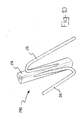
- Figure 1 is a schematic perspective exploded view of an portion of an intramedullary nail, suitable for insertion in a fractured elongate bone, according to the present invention.
- Figure 2 is a schematic side-elevation view of the nail of figure 1, in a different configuration.
- Figure 3 is a schematic plan view from above of the nail of figure 2.
- Figure 4 schematically shows a detail of the nail of figure 1.
- Figure 5 schematically shows a detail of the nail of figure 2.
- Figure 6 is a schematic plan view from above of a first alternative embodiment of a nail according to the present invention.
- Figure 7 schematically shows a cross-section of the nail of figure 6, taken according to the traced VII-VII plane of figure 6.
- Figure 8 is a schematic plan view from above of the nail of figure 6, in a different configuration.
- Figure 9 schematically shows a cross-section of the nail of figure 8, taken according to the traced IX-IX plane of figure 8.
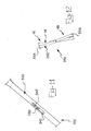
- Figure 10 is a schematic perspective view of a portion of a second alternative embodiment of the intramedullary nail according to the present invention.
- Figure 11 is a schematic perspective view of a third alternative embodiment of an intramedullary nail according to the present invention.
- Figure 12 is a schematic perspective view of the intramedullary nail of figure 12, in a different configuration.
-
- With reference to the drawings, an intramedullary nail according to the present invention is shown in a first embodiment and in three further alternative embodiments.
- The nail, in the embodiment described at first, is globally indicated with 10, while in the alternative embodiments the nail of the invention is indicated with 110, 210 and 310 respectively. It is specified that, in these alternative embodiments, the elements being structurally or functionally similar to the elements of the
nail 10 are indicated with the same reference number and the detailed description thereof is not repeated for short. - The
nail 10 shown in figures 1, 2 and 3, which is suitable for insertion in a fractured elongate bone 12, such as for example a femur or a tibia, comprises a substantiallystraight stem 14, having a predetermined axis X-X, extending between aproximal end 16 and adistal end 18. - According to an aspect of the present invention, the
nail 10 comprises expansion means 20 for the nail fixation to the bone, said expansion means 20 being operable by at least onedriving element 22 realised with a shape-memory material. - Shape memory material means a material having a given initial starting shape and taking, under predetermined external conditions (for example a temperature rise and/or drop) or undergoing a predetermined activation condition, i.e. after a so-called "material instruction" step, a given new shape.
- Known shape-memory materials suitable for use in the present invention are, for instance, certain nickel-titanium alloys.
- The invention is based on the following principle: subjecting an element realised in a shape memory material, having a predetermined initial shape at rest, to said so-called "material instruction" step (for example to a predetermined temperature variation), said element takes a shape being maintained as long as the "instruction" step effect persists; said shape, being different from the initial shape, can be called transient shape and it is temporary or unstable. When the "instruction" step effect stops, the element leaves said transient shape and, coming back towards the initial shape, takes a working shape. Depending on the type of material and on the working temperature, in the working shape, said material can arrive at the initial shape or it can go further on the initial shape, arriving at a final shape. It is worth pointing out that the more this final shape is far from the initial shape, the more the available shape memory energy of the material is high.
- The invention has been reached as result of the intuition that an element realised in a shape memory material, in the passage from the transient shape towards the working shape, can create the fixing of the intramedullary nail in the bone.
- In the example of figures 1, 2 and 3, the
stem 14 comprises a plurality oflongitudinal portions 24 forming, close to each other, a cylindrical tubular body. - In other words, the
longitudinal portions 24 have a circular-crown-sector-shaped section. In the case being shown, thelongitudinal portions 24 are four and the angle at the circular crown sector centre is a right angle. - Expansion means 20 shape in said
longitudinal portions 24, which can be radially spaced apart from the axis X-X of thestem 14. - Said at least one
driving element 22, for example in the shape of a V-or-U-bentcylindrical body 26, is provided between thelongitudinal portions 24. The cross section of thecylindrical body 26 can be, for example, circular or square. - The
cylindrical body 26 is fixed, at the two opposite ends, to twolongitudinal portions 24, generally in correspondence with surfaces being turned towards the axis X-X. - Preferably,
recesses 28, being accessible from the axis X-X, are provided in saidlongitudinal portions 24. Saidrecesses 28 of thelongitudinal portions 24 are conjugate to each other: in other words, when thelongitudinal portions 24 are close to each other, saidrecesses 28 define anarea 30 comprising said bentcylindrical body 26 which is connected, at two opposite ends, to the twolongitudinal portions 24 being concerned. - In the case of the four
longitudinal portions 24 being shown, fourcylindrical bodies 26 are provided in correspondence with eachend stem 14. Preferably, the fourcylindrical bodies 26 of eachend - In the initial shape, shown in figure 1, the
longitudinal portions 24 are close to each other and thecylindrical bodies 26 are bent. - In the final shape, shown in figures 2 and 3, i.e. when the shape-memory material of the
cylindrical bodies 26 is activated, thecylindrical bodies 26 tend to straighten, i.e. the angle between the directions of two opposite ends tends to increase, as it can be seen by comparing figures 4 and 5 showing acylindrical body 26 in the initial shape and in the final shape. As a consequence of this straightening, thelongitudinal portions 24, connected by means of thecylindrical bodies 26, are spaced apart, having moved in a substantially radial direction with respect to the axis X-X. - In the alternative embodiment of figures 6, 7, 8 and 9, the
nail 110 according to the invention is shown, wherein at least onedriving element 22, shaping in aX-shaped structure 126, is provided between thelongitudinal portions 24. - The
structure 126 has thus fourends adjacent ends structure 126 is fixed to twolongitudinal portions 24, generally in correspondence with surfaces being turned towards the axis X-X. The fixation is performed for example through buckling with plastic deformation. - Preferably,
grooves 128, being accessible from the axis X-X, are provided in saidlongitudinal portions 24. Saidgrooves 128 of thelongitudinal portions 24 are conjugate to each other: in other words, when thelongitudinal portions 24 are close to each other, saidgrooves 128 define anarea 130 comprising saidstructure 126 when being bent, i.e. when the two firstadjacent ends adjacent ends - The two remaining
ends grooves 128. - In the case being shown, the
longitudinal portions 24 are four and fourstructures 126 are provided in correspondence with eachend stem 14. Preferably, the fourstructures 126 of eachend - In the initial shape, shown in figures 6 and 7, the
longitudinal portions 24 are close to each other and thestructures 126 are bent as above described. - In the final shape, shown in figures 8 and 9, i.e. when the shape-memory material of the
structures 126 is activated, the first twoadjacent ends grooves 128, i.e. thestructures 126 become X-shaped. As a consequence of this straightening, thelongitudinal portions 24, connected by means of thestructures 126, are spaced apart, having moved in a substantially radial direction with respect to the axis X-X. - It must be noticed that the
X-shaped structures 126 can be alternatively obtained by joining pairs of V-or-U-bentcylindrical bodies 26, in correspondence with the bent area. It is evident that in this case, in order to achieve the same effect asstructures 126, thecylindrical bodies 26 will be so instructed as to be bent in the final shape and to be substantially straight in the initial shape. - In the alternative embodiment of figure 10, the
nail 210 according to the invention is shown, which is similar to thenail 10 and it has thus V-or-U-bentcylindrical bodies 26. However, in this alternative embodiment the adjacentcylindrical bodies 26 are positioned with the bend arranged on opposite sides: in other words, in the case of fourlongitudinal portions 24 with fourcylindrical bodies 26, thecylindrical bodies 26, which face to each other, are specular. - It must be noticed that the radial expansion is linked to the length of the
cylindrical bodies 26. - In the alternative embodiment of figures 11 and 12, the
nail 310 according to the invention is shown, wherein expansion means 20 shape in arod 332, twoopposite ends rod 332 being spaceable in a substantially radial way from the axis X-X of thestem 14. - More precisely, the
rod 332 is hinged, in an intermediate position thereof, on thestem 14 by means of apin 338. In particular, therod 332 is hinged in an intermediate position of thestem 14. - The
rod 332 is rectangle-shaped and substantially as long as thestem 14. Therod 332 is also equipped with agroove 340, in correspondence with the area wherein thepin 338 is positioned. Atorsion spring 342 realised with a shape-memory material is positioned around the pin 338: this is the drivingelement 22 of thenail 310. - An end of the
spring 342 is constrained to thestem 14, while the opposite end is positioned in front of a wall of thegroove 340, or preferably it is connected thereto. - In the final shape, the
spring 342 is expanded, with an increase in the angle between the two ends of thespring 342 causing, through the thrust of the opposite end of thespring 342 on the wall of thegroove 340, a rotation of therod 332. - The
rod 332 is preferably equipped, at the two ends 334 and 336, with sharp portions for an improved fixation of thenail 310. - An application method of an intramedullary nail according to the present invention in said fractured elongate bone 12 comprises:
- a positioning step of said nail in said elongate bone 12, to mend the fracture;
- an operation step of said expansion means 20 for the nail fixation to the
bone, said expansion means 20 being operated by at least one driving
element 22 realised with a shape-memory material. -
- The operation of the
intramedullary nail 10, suitable for insertion in a fractured elongate bone 12, according to the present invention, is already partially evident from the description of the above application method and it is specified hereafter. - The nail according to the invention is positioned in said elongate bone 12, in the initial shape thereof.
- Afterwards, in order to fix the nail to the bone 12, said driving
element 22 realised with a shape-memory material is operated. - In the first three embodiments, the
longitudinal portions 24 radially space apart up to realise an interference with the medullary canal surfaces surrounding thelongitudinal portions 24. - This interference practically causes a grip, solidly fixing the nail in the bone 12.
- In the forth embodiment, considering that the
stem 14 can be very long, theends rod 332 space apart in a substantially radial way from the axis X-X of thestem 14. - These ends 334 and 336 realise an interference with the bone portion surrounding them. This interference practically causes a grip, solidly fixing the nail in the bone 12.
- The main advantage achieved by the intramedullary nail suitable for insertion in a fractured elongate bone, as well as by the application method of said nail in said fractured bone, according to the present invention, is the fact of unusually simplifying the fixation step of the intramedullary nail inserted in the fractured bone. In practise, the nail fixation is obtained simultaneously with the insertion thereof in the bone, since the shape-memory elements, cooled at first to take the initial shape, take in the bone their final shape, due to the heat released by the patient's body.
- Another advantage of the intramedullary nail according to the present invention, is to prevent undesired nail torsions or rotations in the bone during the application step.
- For the first three embodiments, it must be noticed how advantageously the network formed by the
cylindrical bodies 26 or by theX-shaped structures 126 and by thelongitudinal portions 24 gives an excellent structural resistance to the nail of the invention. - In the case of the forth embodiment, it must be noticed how advantageously the
torsion spring 342 ensures a considerable rotation of therod 332. - Obviously, in order to meet specific and contingent requirements, a skilled in the art could bring several changes to the above-described intramedullary nail suitable for insertion in a fractured elongate bone and application method of said nail in said bone, all however comprised in the scope of protection of the present invention, as defined in the following claims.
Claims (39)
- Intramedullary nail (10, 110, 210, 310) suitable for insertion in a fractured elongate bone (12), comprising a substantially straight stem (14), having a predetermined axis (X-X), extending between a proximal end (16) and a distal end (18), characterised in that it comprises expansion means (20) for the nail fixation to the bone, said expansion means (20) being operable by at least one driving element (22) realised with a shape-memory material.
- Intramedullary nail (10, 110, 210) according to claim 1, characterised in that the stem (14) comprises a plurality of longitudinal portions (24) forming, close to each other, a cylindrical tubular body.
- Intramedullary nail (10, 110, 210) according to claim 2, characterised in that the longitudinal portions (24) are four.
- Intramedullary nail (10, 110, 210) according to claim 2, characterised in that expansion means (20) shape in said longitudinal portions (24), which can be radially spaced apart from the axis (X-X) of the stem (14).
- Intramedullary nail (10, 110, 210) according to claim 2, characterised in that said at least one driving element (22) is provided between the longitudinal portions (24).
- Intramedullary nail (10, 210) according to claim 5, characterised in that said at least one driving element (22) is in the shape of a V-or-U-bent cylindrical body (26).
- Intramedullary nail (10, 110, 210) according to claim 6, characterised in that the cylindrical body (26) is fixed, at the two opposite ends, to two longitudinal portions (24).
- Intramedullary nail (10, 110, 210) according to claim 7, characterised in that the cylindrical body (26) is fixed in correspondence with surfaces being turned towards the axis (X-X) of the stem (14).
- Intramedullary nail (10, 110) according to claim 8, characterised in that recesses (28), being accessible from the axis (X-X) of the stem (14), are provided in said longitudinal portions (24), said recesses (28) of the longitudinal portions (24) being conjugate to each other, so as to define, when the longitudinal portions (24) are close to each other, an area (30) comprising said bent cylindrical body (26) which is connected, at two opposite ends, to said two longitudinal portions (24).
- Intramedullary nail (10, 210) according to claims 3 and 6, characterised in that four cylindrical bodies (26) are provided in correspondence with each end (16, 18) of the stem (14).
- Intramedullary nail (10, 210) according to claim 10, characterised in that the four cylindrical bodies (26) of each end (16, 18) are symmetrically positioned with respect to the axis (X-X) of the stem (14).
- Intramedullary nail (10, 210) according to claim 11, characterised in that the four cylindrical bodies (26) of each end (16, 18) are positioned at a same height with respect to the axis (X-X) of the stem (14).
- Intramedullary nail (10, 210) according to claim 6, characterised in that, in the shape preceding the nail fixation, the longitudinal portions (24) are close to each other and the cylindrical bodies (26) are bent.
- Intramedullary nail (10, 210) according to claim 6, characterised in that, when the shape-memory material of the cylindrical bodies (26) is activated, the cylindrical bodies (26) tend to straighten.
- Intramedullary nail (110) according to claim 2, characterised in that at least one driving element (22), shaping in a X-shaped structure (126) is provided between the longitudinal portions (24).
- Intramedullary nail (110) according to claim 15, characterised in that, in correspondence with two first adjacent ends (126a, 126b) of the structure (126), the structure (126) is fixed to two longitudinal portions (24).
- Intramedullary nail (110) according to claim 16, characterised in that the structure (126) is fixed in correspondence with surfaces being turned towards the axis (X-X) of the stem (14).
- Intramedullary nail (110) according to claim 17, characterised in that the fixation of the structure (126) is performed through buckling with plastic deformation.
- Intramedullary nail (110) according to claim 16, characterised in that grooves (128), being accessible from the axis (X-X) of the stem (14), are provided in said longitudinal portions (24), said grooves (128) being conjugate to each other so as to define, when the longitudinal portions (24) are close to each other, an area (130) comprising said structure (126) when being bent, i.e. when said two first adjacent ends (126a, 126b) are close to each other and when also the two remaining adjacent ends (126c, 126d) are close to each other.
- Intramedullary nail (110) according to claim 19, characterised in that said two remaining ends (126c, 126d) are slideble in said grooves (128).
- Intramedullary nail (110) according to claim 15, characterised in that the longitudinal portions (24) are four and four structures (126) are provided in correspondence of each end (16, 18) of the stem (14).
- Intramedullary nail (110) according to claim 21, characterised in that the four structure (126) of each end (16, 18) are symmetrically positioned with respect to the axis (X-X) of the stem (14).
- Intramedullary nail (110) according to claim 22, characterised in that the four structures (126) of each end (16, 18) are positioned at a same height with respect to the axis (X-X) of the stem (14).
- Intramedullary nail (110) according to claim 15, characterised in that, in the shape preceding the nail fixation, the longitudinal portions (24) are close to each other and the structures (126) are bent.
- Intramedullary nail (110) according to claim 20, characterised in that, when the shape-memory material of the structures (126) is activated, the first two adjacent ends (126a, 126b) tend to space apart, as the remaining adjacent ends (126c, 126d) tend to space apart by sliding in the grooves (128).
- Intramedullary nail (110) according to claim 15, characterised in that the X-shaped structures (126) are obtained by joining pairs of V-or-U-bent cylindrical bodies (26), in correspondence with the bent area.
- Intramedullary nail (210) according to claim 6, characterised in that the adjacent cylindrical bodies (26) are positioned with the bend arranged on opposite sides.
- Intramedullary nail (310) according to claim 1, characterised in that expansion means (20) shape in a rod (332), two opposite ends (334, 336) of said rod (332) being spaceable in a substantially radial way from the axis (X-X) of the stem (14).
- Intramedullary nail (310) according to claim 28, characterised in that the rod (332) is hinged, in an intermediate position thereof, on the stem (14) by means of a pin (338).
- Intramedullary nail (310) according to claim 29, characterised in that the rod (332) is hinged in an intermediate position of the stem (14).
- Intramedullary nail (310) according to claim 30, characterised in that the rod (332) is rectangle-shaped and substantially as long as the stem (14).
- Intramedullary nail (310) according to claim 29, characterised in that the rod (332) is equipped with a groove (340) in correspondence with the area wherein the pin (338) is positioned (340).
- Intramedullary nail (310) according to claim 32, characterised in that a torsion spring (342), realised with a shape-memory material and being the driving element (22) of the nail (310), is positioned around the pin (338).
- Intramedullary nail (310) according to claim 33, characterised in that an end of the spring (342) is constrained to the stem (14), while the opposite end is positioned in front of a wall of the groove (340).
- Intramedullary nail (310) according to claim 33, characterised in that an end of the spring (342) is constrained to the stem (14), while the opposite end is connected to a wall of the groove (340).
- Intramedullary nail (310) according to claims 34 or 35, characterised in that, when the shape-memory material of the spring (342) is activated, the spring (342) is expanded, with an increase in the angle between the two ends of the spring (342).
- Intramedullary nail (310) according to claim 28, characterised in that the rod (332) is equipped at the two ends (334, 336) with sharp portions.
- Intramedullary nail (10, 110, 210, 310) according to claim 1, characterised in that the fractured elongate bone (12) is a femur or a tibia.
- Application method, in a fractured elongate bone (12), of an intramedullary nail (10, 110, 210, 310) according to claim 1, characterised in that it comprises:a positioning step of said nail (10, 110, 210, 310) in said elongate bone (12), to mend the fracture;an operation step of said expansion means (20) for the nail fixation to the bone, said expansion means (20) being operated by at least one driving element (22) realised with a shape-memory material.
Priority Applications (2)
| Application Number | Priority Date | Filing Date | Title |
|---|---|---|---|
| EP04007790A EP1582164A1 (en) | 2004-03-31 | 2004-03-31 | Intramedullary nail comprising a stem whereon longitudinal portions are provided driving elements of shape-memory material |
| PCT/EP2005/003392 WO2005094705A2 (en) | 2004-03-31 | 2005-03-31 | Shape memory alloy comprising intramedullary nail provided with expansion fixing means |
Applications Claiming Priority (1)
| Application Number | Priority Date | Filing Date | Title |
|---|---|---|---|
| EP04007790A EP1582164A1 (en) | 2004-03-31 | 2004-03-31 | Intramedullary nail comprising a stem whereon longitudinal portions are provided driving elements of shape-memory material |
Publications (1)
| Publication Number | Publication Date |
|---|---|
| EP1582164A1 true EP1582164A1 (en) | 2005-10-05 |
Family
ID=34878224
Family Applications (1)
| Application Number | Title | Priority Date | Filing Date |
|---|---|---|---|
| EP04007790A Withdrawn EP1582164A1 (en) | 2004-03-31 | 2004-03-31 | Intramedullary nail comprising a stem whereon longitudinal portions are provided driving elements of shape-memory material |
Country Status (1)
| Country | Link |
|---|---|
| EP (1) | EP1582164A1 (en) |
Cited By (10)
| Publication number | Priority date | Publication date | Assignee | Title |
|---|---|---|---|---|
| US8128627B2 (en) | 2007-03-22 | 2012-03-06 | Sonoma Orthopedic Products, Inc. | Segmented intramedullary system and apparatus |
| US8287538B2 (en) | 2008-01-14 | 2012-10-16 | Conventus Orthopaedics, Inc. | Apparatus and methods for fracture repair |
| US8906022B2 (en) | 2010-03-08 | 2014-12-09 | Conventus Orthopaedics, Inc. | Apparatus and methods for securing a bone implant |
| US8961518B2 (en) | 2010-01-20 | 2015-02-24 | Conventus Orthopaedics, Inc. | Apparatus and methods for bone access and cavity preparation |
| US9522022B2 (en) | 2013-11-18 | 2016-12-20 | Biomedical Enterprises, Inc. | Method and appparatus for an intramedullary implant and method of implantation therefor |
| US9636155B2 (en) | 2013-11-18 | 2017-05-02 | Biomedical Enterprises, Inc. | Method and apparatus for an intramudullary implant and method of implantation thereof |
| US9730739B2 (en) | 2010-01-15 | 2017-08-15 | Conventus Orthopaedics, Inc. | Rotary-rigid orthopaedic rod |
| US9775659B2 (en) | 2010-10-04 | 2017-10-03 | Biomedical Enterprises, Inc. | Method and system for storing and inserting an implant |
| US10022132B2 (en) | 2013-12-12 | 2018-07-17 | Conventus Orthopaedics, Inc. | Tissue displacement tools and methods |
| US10918426B2 (en) | 2017-07-04 | 2021-02-16 | Conventus Orthopaedics, Inc. | Apparatus and methods for treatment of a bone |
Citations (4)
| Publication number | Priority date | Publication date | Assignee | Title |
|---|---|---|---|---|
| EP0772420A1 (en) | 1994-07-28 | 1997-05-14 | ORTHOFIX S.r.l. | Device for mechanical alignment of bone screws in a medullary nail |
| WO1998051228A1 (en) * | 1997-05-12 | 1998-11-19 | University Of Aberdeen | Retractable intramedullary nail |
| US6127597A (en) * | 1997-03-07 | 2000-10-03 | Discotech N.V. | Systems for percutaneous bone and spinal stabilization, fixation and repair |
| WO2001028443A1 (en) * | 1999-10-22 | 2001-04-26 | Mark Levy | Expandable orthopedic device |
-
2004
- 2004-03-31 EP EP04007790A patent/EP1582164A1/en not_active Withdrawn
Patent Citations (4)
| Publication number | Priority date | Publication date | Assignee | Title |
|---|---|---|---|---|
| EP0772420A1 (en) | 1994-07-28 | 1997-05-14 | ORTHOFIX S.r.l. | Device for mechanical alignment of bone screws in a medullary nail |
| US6127597A (en) * | 1997-03-07 | 2000-10-03 | Discotech N.V. | Systems for percutaneous bone and spinal stabilization, fixation and repair |
| WO1998051228A1 (en) * | 1997-05-12 | 1998-11-19 | University Of Aberdeen | Retractable intramedullary nail |
| WO2001028443A1 (en) * | 1999-10-22 | 2001-04-26 | Mark Levy | Expandable orthopedic device |
Cited By (20)
| Publication number | Priority date | Publication date | Assignee | Title |
|---|---|---|---|---|
| US8496658B2 (en) | 2007-03-22 | 2013-07-30 | Sonoma Orthopedic Products, Inc. | Segmented intramedullary structure |
| US8128627B2 (en) | 2007-03-22 | 2012-03-06 | Sonoma Orthopedic Products, Inc. | Segmented intramedullary system and apparatus |
| US8430879B2 (en) | 2007-03-22 | 2013-04-30 | Sonoma Orthopedic Products, Inc. | Segmented intramedullary structure |
| US9517093B2 (en) | 2008-01-14 | 2016-12-13 | Conventus Orthopaedics, Inc. | Apparatus and methods for fracture repair |
| US11399878B2 (en) | 2008-01-14 | 2022-08-02 | Conventus Orthopaedics, Inc. | Apparatus and methods for fracture repair |
| US10603087B2 (en) | 2008-01-14 | 2020-03-31 | Conventus Orthopaedics, Inc. | Apparatus and methods for fracture repair |
| US8287538B2 (en) | 2008-01-14 | 2012-10-16 | Conventus Orthopaedics, Inc. | Apparatus and methods for fracture repair |
| US9788870B2 (en) | 2008-01-14 | 2017-10-17 | Conventus Orthopaedics, Inc. | Apparatus and methods for fracture repair |
| US9730739B2 (en) | 2010-01-15 | 2017-08-15 | Conventus Orthopaedics, Inc. | Rotary-rigid orthopaedic rod |
| US8961518B2 (en) | 2010-01-20 | 2015-02-24 | Conventus Orthopaedics, Inc. | Apparatus and methods for bone access and cavity preparation |
| US9848889B2 (en) | 2010-01-20 | 2017-12-26 | Conventus Orthopaedics, Inc. | Apparatus and methods for bone access and cavity preparation |
| US8906022B2 (en) | 2010-03-08 | 2014-12-09 | Conventus Orthopaedics, Inc. | Apparatus and methods for securing a bone implant |
| US9993277B2 (en) | 2010-03-08 | 2018-06-12 | Conventus Orthopaedics, Inc. | Apparatus and methods for securing a bone implant |
| US9775659B2 (en) | 2010-10-04 | 2017-10-03 | Biomedical Enterprises, Inc. | Method and system for storing and inserting an implant |
| US9775656B2 (en) | 2013-11-18 | 2017-10-03 | Biomedical Enterprises, Inc. | Method and appparatus for an intramedullary implant and method of implantation therefor |
| US9636155B2 (en) | 2013-11-18 | 2017-05-02 | Biomedical Enterprises, Inc. | Method and apparatus for an intramudullary implant and method of implantation thereof |
| US9522022B2 (en) | 2013-11-18 | 2016-12-20 | Biomedical Enterprises, Inc. | Method and appparatus for an intramedullary implant and method of implantation therefor |
| US10022132B2 (en) | 2013-12-12 | 2018-07-17 | Conventus Orthopaedics, Inc. | Tissue displacement tools and methods |
| US10076342B2 (en) | 2013-12-12 | 2018-09-18 | Conventus Orthopaedics, Inc. | Tissue displacement tools and methods |
| US10918426B2 (en) | 2017-07-04 | 2021-02-16 | Conventus Orthopaedics, Inc. | Apparatus and methods for treatment of a bone |
Similar Documents
| Publication | Publication Date | Title |
|---|---|---|
| WO2005094705A2 (en) | Shape memory alloy comprising intramedullary nail provided with expansion fixing means | |
| US11284887B2 (en) | Bone implant with means for multi directional force and means of insertion | |
| EP1740113B1 (en) | Intramedullary nail comprising elements of shape-memory material | |
| EP1582159A1 (en) | Intramedullary nail provided with expansion means for fixation to the bone | |
| US20200138433A1 (en) | Bone staple, instrument and method of use and manufacturing | |
| JP6539652B2 (en) | Tissue displacement tools and methods | |
| EP1582163A1 (en) | Intramedullary nail comprising an helical element of shape-memory material | |
| EP3166522B1 (en) | Bone implant and means of insertion | |
| US20170209193A1 (en) | Bone implant with means for multi directional force and means of insertion | |
| US20140276830A1 (en) | Bone staples and methods of use therefor and manufacturing thereof | |
| EP1582164A1 (en) | Intramedullary nail comprising a stem whereon longitudinal portions are provided driving elements of shape-memory material | |
| US20100274246A1 (en) | Expandable intramedullary nail for small bone fixation | |
| EP1582161A1 (en) | Intramedullary nail provided with expansion fixing means operated by one or more driving elements | |
| EP1582160A1 (en) | Intramedullary nail comprising elements of shape-memory material | |
| EP1582162A1 (en) | Intramedullary nail provided with expansion fixing means comprising at least one element of shape-retention material | |
| US20220061837A1 (en) | Orthopedic torsion generated compression implants and methods for using same |
Legal Events
| Date | Code | Title | Description |
|---|---|---|---|
| PUAI | Public reference made under article 153(3) epc to a published international application that has entered the european phase |
Free format text: ORIGINAL CODE: 0009012 |
|
| AK | Designated contracting states |
Kind code of ref document: A1 Designated state(s): AT BE BG CH CY CZ DE DK EE ES FI FR GB GR HU IE IT LI LU MC NL PL PT RO SE SI SK TR |
|
| AX | Request for extension of the european patent |
Extension state: AL LT LV MK |
|
| AKX | Designation fees paid | ||
| REG | Reference to a national code |
Ref country code: DE Ref legal event code: 8566 |
|
| STAA | Information on the status of an ep patent application or granted ep patent |
Free format text: STATUS: THE APPLICATION IS DEEMED TO BE WITHDRAWN |
|
| 18D | Application deemed to be withdrawn |
Effective date: 20060406 |