EP1586276B1 - Stabilising device for bones and method of fabrication of an elastic element - Google Patents
Stabilising device for bones and method of fabrication of an elastic element Download PDFInfo
- Publication number
- EP1586276B1 EP1586276B1 EP05008060A EP05008060A EP1586276B1 EP 1586276 B1 EP1586276 B1 EP 1586276B1 EP 05008060 A EP05008060 A EP 05008060A EP 05008060 A EP05008060 A EP 05008060A EP 1586276 B1 EP1586276 B1 EP 1586276B1
- Authority
- EP
- European Patent Office
- Prior art keywords
- elastic element
- elastic
- rod
- stabilization device
- bore
- Prior art date
- Legal status (The legal status is an assumption and is not a legal conclusion. Google has not performed a legal analysis and makes no representation as to the accuracy of the status listed.)
- Not-in-force
Links
Images


Classifications
-
- A—HUMAN NECESSITIES
- A61—MEDICAL OR VETERINARY SCIENCE; HYGIENE
- A61B—DIAGNOSIS; SURGERY; IDENTIFICATION
- A61B17/00—Surgical instruments, devices or methods, e.g. tourniquets
- A61B17/56—Surgical instruments or methods for treatment of bones or joints; Devices specially adapted therefor
- A61B17/58—Surgical instruments or methods for treatment of bones or joints; Devices specially adapted therefor for osteosynthesis, e.g. bone plates, screws, setting implements or the like
- A61B17/68—Internal fixation devices, including fasteners and spinal fixators, even if a part thereof projects from the skin
- A61B17/70—Spinal positioners or stabilisers ; Bone stabilisers comprising fluid filler in an implant
- A61B17/7001—Screws or hooks combined with longitudinal elements which do not contact vertebrae
- A61B17/7032—Screws or hooks with U-shaped head or back through which longitudinal rods pass
-
- F—MECHANICAL ENGINEERING; LIGHTING; HEATING; WEAPONS; BLASTING
- F21—LIGHTING
- F21K—NON-ELECTRIC LIGHT SOURCES USING LUMINESCENCE; LIGHT SOURCES USING ELECTROCHEMILUMINESCENCE; LIGHT SOURCES USING CHARGES OF COMBUSTIBLE MATERIAL; LIGHT SOURCES USING SEMICONDUCTOR DEVICES AS LIGHT-GENERATING ELEMENTS; LIGHT SOURCES NOT OTHERWISE PROVIDED FOR
- F21K9/00—Light sources using semiconductor devices as light-generating elements, e.g. using light-emitting diodes [LED] or lasers
- F21K9/20—Light sources comprising attachment means
- F21K9/23—Retrofit light sources for lighting devices with a single fitting for each light source, e.g. for substitution of incandescent lamps with bayonet or threaded fittings
- F21K9/238—Arrangement or mounting of circuit elements integrated in the light source
-
- A—HUMAN NECESSITIES
- A61—MEDICAL OR VETERINARY SCIENCE; HYGIENE
- A61B—DIAGNOSIS; SURGERY; IDENTIFICATION
- A61B17/00—Surgical instruments, devices or methods, e.g. tourniquets
- A61B17/56—Surgical instruments or methods for treatment of bones or joints; Devices specially adapted therefor
- A61B17/58—Surgical instruments or methods for treatment of bones or joints; Devices specially adapted therefor for osteosynthesis, e.g. bone plates, screws, setting implements or the like
- A61B17/68—Internal fixation devices, including fasteners and spinal fixators, even if a part thereof projects from the skin
- A61B17/70—Spinal positioners or stabilisers ; Bone stabilisers comprising fluid filler in an implant
- A61B17/7001—Screws or hooks combined with longitudinal elements which do not contact vertebrae
- A61B17/7002—Longitudinal elements, e.g. rods
- A61B17/7004—Longitudinal elements, e.g. rods with a cross-section which varies along its length
-
- A—HUMAN NECESSITIES
- A61—MEDICAL OR VETERINARY SCIENCE; HYGIENE
- A61B—DIAGNOSIS; SURGERY; IDENTIFICATION
- A61B17/00—Surgical instruments, devices or methods, e.g. tourniquets
- A61B17/56—Surgical instruments or methods for treatment of bones or joints; Devices specially adapted therefor
- A61B17/58—Surgical instruments or methods for treatment of bones or joints; Devices specially adapted therefor for osteosynthesis, e.g. bone plates, screws, setting implements or the like
- A61B17/68—Internal fixation devices, including fasteners and spinal fixators, even if a part thereof projects from the skin
- A61B17/70—Spinal positioners or stabilisers ; Bone stabilisers comprising fluid filler in an implant
- A61B17/7001—Screws or hooks combined with longitudinal elements which do not contact vertebrae
- A61B17/7002—Longitudinal elements, e.g. rods
- A61B17/7019—Longitudinal elements having flexible parts, or parts connected together, such that after implantation the elements can move relative to each other
- A61B17/7026—Longitudinal elements having flexible parts, or parts connected together, such that after implantation the elements can move relative to each other with a part that is flexible due to its form
- A61B17/7028—Longitudinal elements having flexible parts, or parts connected together, such that after implantation the elements can move relative to each other with a part that is flexible due to its form the flexible part being a coil spring
-
- A—HUMAN NECESSITIES
- A61—MEDICAL OR VETERINARY SCIENCE; HYGIENE
- A61B—DIAGNOSIS; SURGERY; IDENTIFICATION
- A61B17/00—Surgical instruments, devices or methods, e.g. tourniquets
- A61B17/56—Surgical instruments or methods for treatment of bones or joints; Devices specially adapted therefor
- A61B17/58—Surgical instruments or methods for treatment of bones or joints; Devices specially adapted therefor for osteosynthesis, e.g. bone plates, screws, setting implements or the like
- A61B17/68—Internal fixation devices, including fasteners and spinal fixators, even if a part thereof projects from the skin
- A61B17/70—Spinal positioners or stabilisers ; Bone stabilisers comprising fluid filler in an implant
- A61B17/7001—Screws or hooks combined with longitudinal elements which do not contact vertebrae
- A61B17/7035—Screws or hooks, wherein a rod-clamping part and a bone-anchoring part can pivot relative to each other
- A61B17/7037—Screws or hooks, wherein a rod-clamping part and a bone-anchoring part can pivot relative to each other wherein pivoting is blocked when the rod is clamped
-
- A—HUMAN NECESSITIES
- A61—MEDICAL OR VETERINARY SCIENCE; HYGIENE
- A61B—DIAGNOSIS; SURGERY; IDENTIFICATION
- A61B17/00—Surgical instruments, devices or methods, e.g. tourniquets
- A61B17/56—Surgical instruments or methods for treatment of bones or joints; Devices specially adapted therefor
- A61B17/58—Surgical instruments or methods for treatment of bones or joints; Devices specially adapted therefor for osteosynthesis, e.g. bone plates, screws, setting implements or the like
- A61B17/68—Internal fixation devices, including fasteners and spinal fixators, even if a part thereof projects from the skin
- A61B17/70—Spinal positioners or stabilisers ; Bone stabilisers comprising fluid filler in an implant
- A61B17/7059—Cortical plates
-
- A—HUMAN NECESSITIES
- A61—MEDICAL OR VETERINARY SCIENCE; HYGIENE
- A61B—DIAGNOSIS; SURGERY; IDENTIFICATION
- A61B17/00—Surgical instruments, devices or methods, e.g. tourniquets
- A61B17/56—Surgical instruments or methods for treatment of bones or joints; Devices specially adapted therefor
- A61B17/58—Surgical instruments or methods for treatment of bones or joints; Devices specially adapted therefor for osteosynthesis, e.g. bone plates, screws, setting implements or the like
- A61B17/68—Internal fixation devices, including fasteners and spinal fixators, even if a part thereof projects from the skin
- A61B17/84—Fasteners therefor or fasteners being internal fixation devices
- A61B17/86—Pins or screws or threaded wires; nuts therefor
- A61B17/8625—Shanks, i.e. parts contacting bone tissue
-
- B—PERFORMING OPERATIONS; TRANSPORTING
- B23—MACHINE TOOLS; METAL-WORKING NOT OTHERWISE PROVIDED FOR
- B23C—MILLING
- B23C3/00—Milling particular work; Special milling operations; Machines therefor
- B23C3/28—Grooving workpieces
- B23C3/32—Milling helical grooves, e.g. in making twist-drills
-
- B—PERFORMING OPERATIONS; TRANSPORTING
- B23—MACHINE TOOLS; METAL-WORKING NOT OTHERWISE PROVIDED FOR
- B23H—WORKING OF METAL BY THE ACTION OF A HIGH CONCENTRATION OF ELECTRIC CURRENT ON A WORKPIECE USING AN ELECTRODE WHICH TAKES THE PLACE OF A TOOL; SUCH WORKING COMBINED WITH OTHER FORMS OF WORKING OF METAL
- B23H7/00—Processes or apparatus applicable to both electrical discharge machining and electrochemical machining
- B23H7/02—Wire-cutting
-
- B—PERFORMING OPERATIONS; TRANSPORTING
- B23—MACHINE TOOLS; METAL-WORKING NOT OTHERWISE PROVIDED FOR
- B23P—METAL-WORKING NOT OTHERWISE PROVIDED FOR; COMBINED OPERATIONS; UNIVERSAL MACHINE TOOLS
- B23P13/00—Making metal objects by operations essentially involving machining but not covered by a single other subclass
- B23P13/02—Making metal objects by operations essentially involving machining but not covered by a single other subclass in which only the machining operations are important
-
- F—MECHANICAL ENGINEERING; LIGHTING; HEATING; WEAPONS; BLASTING
- F16—ENGINEERING ELEMENTS AND UNITS; GENERAL MEASURES FOR PRODUCING AND MAINTAINING EFFECTIVE FUNCTIONING OF MACHINES OR INSTALLATIONS; THERMAL INSULATION IN GENERAL
- F16F—SPRINGS; SHOCK-ABSORBERS; MEANS FOR DAMPING VIBRATION
- F16F1/00—Springs
- F16F1/02—Springs made of steel or other material having low internal friction; Wound, torsion, leaf, cup, ring or the like springs, the material of the spring not being relevant
- F16F1/04—Wound springs
-
- F—MECHANICAL ENGINEERING; LIGHTING; HEATING; WEAPONS; BLASTING
- F21—LIGHTING
- F21V—FUNCTIONAL FEATURES OR DETAILS OF LIGHTING DEVICES OR SYSTEMS THEREOF; STRUCTURAL COMBINATIONS OF LIGHTING DEVICES WITH OTHER ARTICLES, NOT OTHERWISE PROVIDED FOR
- F21V17/00—Fastening of component parts of lighting devices, e.g. shades, globes, refractors, reflectors, filters, screens, grids or protective cages
- F21V17/10—Fastening of component parts of lighting devices, e.g. shades, globes, refractors, reflectors, filters, screens, grids or protective cages characterised by specific fastening means or way of fastening
- F21V17/104—Fastening of component parts of lighting devices, e.g. shades, globes, refractors, reflectors, filters, screens, grids or protective cages characterised by specific fastening means or way of fastening using feather joints, e.g. tongues and grooves, with or without friction
-
- A—HUMAN NECESSITIES
- A61—MEDICAL OR VETERINARY SCIENCE; HYGIENE
- A61B—DIAGNOSIS; SURGERY; IDENTIFICATION
- A61B17/00—Surgical instruments, devices or methods, e.g. tourniquets
- A61B17/56—Surgical instruments or methods for treatment of bones or joints; Devices specially adapted therefor
- A61B17/58—Surgical instruments or methods for treatment of bones or joints; Devices specially adapted therefor for osteosynthesis, e.g. bone plates, screws, setting implements or the like
- A61B17/68—Internal fixation devices, including fasteners and spinal fixators, even if a part thereof projects from the skin
- A61B17/70—Spinal positioners or stabilisers ; Bone stabilisers comprising fluid filler in an implant
- A61B17/7062—Devices acting on, attached to, or simulating the effect of, vertebral processes, vertebral facets or ribs ; Tools for such devices
-
- A—HUMAN NECESSITIES
- A61—MEDICAL OR VETERINARY SCIENCE; HYGIENE
- A61B—DIAGNOSIS; SURGERY; IDENTIFICATION
- A61B17/00—Surgical instruments, devices or methods, e.g. tourniquets
- A61B17/56—Surgical instruments or methods for treatment of bones or joints; Devices specially adapted therefor
- A61B17/58—Surgical instruments or methods for treatment of bones or joints; Devices specially adapted therefor for osteosynthesis, e.g. bone plates, screws, setting implements or the like
- A61B17/68—Internal fixation devices, including fasteners and spinal fixators, even if a part thereof projects from the skin
- A61B17/84—Fasteners therefor or fasteners being internal fixation devices
- A61B17/86—Pins or screws or threaded wires; nuts therefor
- A61B17/866—Material or manufacture
-
- A—HUMAN NECESSITIES
- A61—MEDICAL OR VETERINARY SCIENCE; HYGIENE
- A61B—DIAGNOSIS; SURGERY; IDENTIFICATION
- A61B17/00—Surgical instruments, devices or methods, e.g. tourniquets
- A61B2017/00526—Methods of manufacturing
-
- A—HUMAN NECESSITIES
- A61—MEDICAL OR VETERINARY SCIENCE; HYGIENE
- A61B—DIAGNOSIS; SURGERY; IDENTIFICATION
- A61B17/00—Surgical instruments, devices or methods, e.g. tourniquets
- A61B2017/00831—Material properties
- A61B2017/00862—Material properties elastic or resilient
-
- A—HUMAN NECESSITIES
- A61—MEDICAL OR VETERINARY SCIENCE; HYGIENE
- A61F—FILTERS IMPLANTABLE INTO BLOOD VESSELS; PROSTHESES; DEVICES PROVIDING PATENCY TO, OR PREVENTING COLLAPSING OF, TUBULAR STRUCTURES OF THE BODY, e.g. STENTS; ORTHOPAEDIC, NURSING OR CONTRACEPTIVE DEVICES; FOMENTATION; TREATMENT OR PROTECTION OF EYES OR EARS; BANDAGES, DRESSINGS OR ABSORBENT PADS; FIRST-AID KITS
- A61F2/00—Filters implantable into blood vessels; Prostheses, i.e. artificial substitutes or replacements for parts of the body; Appliances for connecting them with the body; Devices providing patency to, or preventing collapsing of, tubular structures of the body, e.g. stents
- A61F2/02—Prostheses implantable into the body
- A61F2/30—Joints
- A61F2/44—Joints for the spine, e.g. vertebrae, spinal discs
- A61F2/4455—Joints for the spine, e.g. vertebrae, spinal discs for the fusion of spinal bodies, e.g. intervertebral fusion of adjacent spinal bodies, e.g. fusion cages
-
- F—MECHANICAL ENGINEERING; LIGHTING; HEATING; WEAPONS; BLASTING
- F16—ENGINEERING ELEMENTS AND UNITS; GENERAL MEASURES FOR PRODUCING AND MAINTAINING EFFECTIVE FUNCTIONING OF MACHINES OR INSTALLATIONS; THERMAL INSULATION IN GENERAL
- F16F—SPRINGS; SHOCK-ABSORBERS; MEANS FOR DAMPING VIBRATION
- F16F1/00—Springs
- F16F1/02—Springs made of steel or other material having low internal friction; Wound, torsion, leaf, cup, ring or the like springs, the material of the spring not being relevant
- F16F1/04—Wound springs
- F16F1/042—Wound springs characterised by the cross-section of the wire
- F16F1/043—Wound springs characterised by the cross-section of the wire the cross-section varying with the wire length
-
- F—MECHANICAL ENGINEERING; LIGHTING; HEATING; WEAPONS; BLASTING
- F21—LIGHTING
- F21Y—INDEXING SCHEME ASSOCIATED WITH SUBCLASSES F21K, F21L, F21S and F21V, RELATING TO THE FORM OR THE KIND OF THE LIGHT SOURCES OR OF THE COLOUR OF THE LIGHT EMITTED
- F21Y2113/00—Combination of light sources
- F21Y2113/10—Combination of light sources of different colours
- F21Y2113/13—Combination of light sources of different colours comprising an assembly of point-like light sources
-
- F—MECHANICAL ENGINEERING; LIGHTING; HEATING; WEAPONS; BLASTING
- F21—LIGHTING
- F21Y—INDEXING SCHEME ASSOCIATED WITH SUBCLASSES F21K, F21L, F21S and F21V, RELATING TO THE FORM OR THE KIND OF THE LIGHT SOURCES OR OF THE COLOUR OF THE LIGHT EMITTED
- F21Y2115/00—Light-generating elements of semiconductor light sources
- F21Y2115/10—Light-emitting diodes [LED]
-
- Y—GENERAL TAGGING OF NEW TECHNOLOGICAL DEVELOPMENTS; GENERAL TAGGING OF CROSS-SECTIONAL TECHNOLOGIES SPANNING OVER SEVERAL SECTIONS OF THE IPC; TECHNICAL SUBJECTS COVERED BY FORMER USPC CROSS-REFERENCE ART COLLECTIONS [XRACs] AND DIGESTS
- Y10—TECHNICAL SUBJECTS COVERED BY FORMER USPC
- Y10T—TECHNICAL SUBJECTS COVERED BY FORMER US CLASSIFICATION
- Y10T29/00—Metal working
- Y10T29/49—Method of mechanical manufacture
- Y10T29/49995—Shaping one-piece blank by removing material
-
- Y—GENERAL TAGGING OF NEW TECHNOLOGICAL DEVELOPMENTS; GENERAL TAGGING OF CROSS-SECTIONAL TECHNOLOGIES SPANNING OVER SEVERAL SECTIONS OF THE IPC; TECHNICAL SUBJECTS COVERED BY FORMER USPC CROSS-REFERENCE ART COLLECTIONS [XRACs] AND DIGESTS
- Y10—TECHNICAL SUBJECTS COVERED BY FORMER USPC
- Y10T—TECHNICAL SUBJECTS COVERED BY FORMER US CLASSIFICATION
- Y10T409/00—Gear cutting, milling, or planing
- Y10T409/30—Milling
- Y10T409/303752—Process
Definitions
- the invention relates to a stabilizing device for bones or vertebrae with an elastic element
- fixation and stabilization devices consist of at least two anchored in the bone or vertebrae and connected via a plate or a rod bone screws.
- Such rigid systems do not allow movement of the relatively fixed bone parts or vertebrae.
- dynamic stabilization is desirable in which the bone parts and vertebrae to be stabilized can perform a controlled limited movement towards each other.
- One possibility for the realization of the dynamic stabilization device is the use of an elastic element instead of a rigid rod connecting the bone anchoring elements.
- a dynamic stabilizing device for vertebrae which has a first and a second screw to be anchored in the vertebrae, each with a receiving part for inserting a spring connecting the screws and such a spring.
- the spring itself is formed as a whole in the form of a coil spring with closely adjacent turns in the manner of a tension spring and is fixed by clamping screws in the receiving parts.
- Another disadvantage of the device is that the elasticity of the spring with otherwise identical spring properties depends on the length of the spring. Furthermore, the bending stiffness of the spring is relatively low, especially for short lengths.
- fixation device for a joint, for example for a wrist or a knee joint, known in which a connected at its ends with bone anchoring elements fixation rod is formed in two parts, wherein the two parts of the fixation rod are connected to each other via a flexible coupling part and wherein the fixation rods to the Coupling part are mounted outside of the body.
- the two parts of the fixation rod are not fixedly connected to the coupling part, but can move freely along a bore in the coupling part.
- the diameter of the coupling part is always larger than the diameter of the fixation rod due to the nature of the connection with the two-part fixation rod.
- This known fixation device is not suitable because of its complicated and voluminous structure for internal use on the spine or other bones.
- the realization of such a flexible coupling part with high bending stiffness requires a large volume of construction
- US 5,423,816 discloses an intervertebral locking device having a helical elastic body, two fastening tabs and two locking elements. Bone chips surround the elastic element and the chambers of the elastic element.
- US 6,197,065 describes a bone fastener assembly for the remaining portion of a long bone diaphysis.
- the assembly includes a main body, an anchor for anchoring the device with respect to the remaining bone portion, and a mounting portion for securing the main body to the anchor.
- the attachment portion has an elastic portion formed as a coil spring.
- the older registration WO 2004/105577 A2 describes a vertebral column stabilization system having one or more flexible members with an opening or a slot.
- the flexible element is integrally formed in a rod having ends that can receive mounting screws.
- two slots or recesses are formed in the rod similar to a double helix. This dockument is state of the art under Article 54 (3) EPC.
- the object is achieved by an e stabilization device according to claim 1.
- the invention has the advantage that an elastic element is formed at the same time compact and with high bending stiffness. This is particularly important for applications on the spinal column and there especially on the cervical spine, where the available space is significantly lower compared to applications on the lumbar spine.
- an elastic element can optionally be combined with rigid rod-shaped elements of different lengths to form an elastic rod-shaped element or combined with different shafts and / or heads to form a bone screw with elastic properties.
- the elastic rod-shaped element or the bone screw then have, depending on the elastic element used predetermined elastic properties such as a certain compression and extension ability in the axial direction, and a certain bending and torsional rigidity.
- the elastic element can be connected with rod-shaped components of different thickness or with plates of different shape and length to be used in spinal and / or trauma surgery.
- FIGS. 4 . 8b . 8c . 8d and 10a-c and 11 are for technical explanation only.
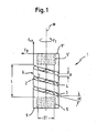
- Fig. 1 an elastic element 1 according to a first embodiment is shown.
- the elastic element 1 is formed as a hollow cylindrical member having a continuous coaxial bore 2 and a first recess 3 running helically with a predetermined pitch and over a predetermined length in the direction of the cylinder axis in the wall, which opens into the bore 2 in the radial direction. Further, a second recess 4 is provided spirally with the same pitch as the first recess 3 over the same length in the direction of the cylinder axis M in the wall between the turns of the first recess 3, which opens into the bore 2 in the radial direction.
- a double helical spring is formed from two helical springs, wherein the turns of the one helical spring extend between the turns of the second helical spring.
- the turns of a coil spring are rotated relative to the turns of the other coil spring about its common center axis by 180 °, so that the first and the second recess are exactly opposite.
- the length L of the spiral recesses 3, 4 in the direction of the cylinder axis, the height H of the recesses, the pitch ⁇ of the helical lines, along which the recesses 3, 4 are formed, and the diameter D1 of the coaxial bore 2 are chosen such that a desired stiffness of the elastic Element against axial forces F ax , bending forces F B and torsional forces F T , which act on the elastic member is given.
- the elastic element 1 Adjacent to its two free ends, the elastic element 1 in each case has a section with an inner thread 5, 5 'extending over a predetermined length. The internal thread portions do not overlap in the axial direction with the portion in which the recesses are formed in the wall.
- the outer diameter of the elastic element 1 is selected according to the respective application.
- the elastic element is formed of a body-friendly material such as titanium.
- Fig. 2 illustrates the construction of a double helical spring 6 as shown by the recesses 3, 4 in the elastic element in Fig. 1 is formed.
- the twin coil spring 6 is composed of two coil springs 7 and 8.
- the two coil springs 7 and 8 are identical and in particular have an identical pitch ⁇ , but the first coil spring 7 in the double helical spring 6 relative to the second coil spring 8 about their common center axis Turned 180 °.
- the turns of the first coil spring 7 extend in the double helical spring 6 therefore in the middle between the turns of the second coil spring 8 and vice versa.
- the pitch of the coil spring is limited by the fact that at least one entire turn must be present in order to obtain good elasticity properties.
- a twin coil spring less than a full turn is required for each of the coil springs to obtain good elasticity properties. Therefore, with the same length, the slope of the Helical spring can be increased compared to a single helical spring.
- An increase in the pitch of the coil spring results in the same length and the same other properties increase the flexural rigidity. Therefore, it is possible with a twin helical spring compared to a single helical spring with the same dimensions to achieve a higher bending stiffness.
- Fig. 3 is shown an elastic element 11 according to a second embodiment.
- the elastic member 11 according to a second embodiment differs from the elastic member 1 according to a first embodiment in that instead of extending from the first to the second end 17 'of the elastic member bore 2 a to the first end 17 of the elastic member adjacent blind bore 12 is provided.
- the blind bore extends over the entire length L of the double helical spring, which is formed as in the first embodiment by a first and a second recess 13 and 14 in the wall of a hollow cylindrical portion. Adjacent to the first end 17, an internal thread 15 is provided in the blind bore.
- the elastic element has a cylindrical projection 16 with an external thread.
- Fig. 4 is shown an elastic element according to a third embodiment.
- the elastic member 20 according to the third embodiment differs from the other embodiments in that no hole coaxial with the center axis M of the elastic member 20 is provided. Furthermore, both to the first end 22, as well as to the second end 22 'adjacent a cylindrical projection 23, 23' provided with an external thread. As in the embodiments described above, two coil springs 26, 27 are formed by two recesses 24, 25.
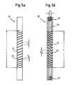
- Fig. 5a is shown an elastic element according to a fourth embodiment.
- Fig. 5b is a sectional view of the elastic element Fig. 5a ,
- the elastic member 30 according to the fourth embodiment differs from that according to the first embodiment in that the pitch ⁇ of the double helical spring forming recesses 31, 32 is not constant but varies along the length L of the double helical spring of the elastic member 30.
- the pitch ⁇ varies such that the distance .DELTA.L of the recesses 31, 32 increases from the free ends of the elastic element 30 toward the center.
- the flexural rigidity of the elastic element 30, which increases as the distance ⁇ L of the recesses 31, 32 increases also varies.
- On the slope of the recesses along the center axis of the elastic element can thus be set specifically a specific location-dependent bending stiffness.
- the elastic member 30 has adjacent each of its two free ends a portion having a predetermined length extending internal thread 33, 33 'and a continuous coaxial bore 34 having an inner diameter D1.
- Fig. 6 is a sectional view of an elastic member according to a fifth embodiment.
- the elastic member 40 according to the fifth embodiment is different from the elastic member 30 according to the fourth embodiment in that the inner diameter D1 of the continuous coaxial bore 42 is not constant but varies along the length L 'of the elastic member 40.
- the inner diameter D1 of the bore 42 varies in such a way that, viewed from the free ends, it decreases toward the middle of the elastic element 40. Accordingly, the flexural rigidity of the elastic member 40, which increases as the inner diameter D1 decreases, also varies. On the inner diameter of the coaxial bore thus a specific location-dependent bending stiffness of the elastic member 40 can be adjusted specifically.
- the elastic member 40 has adjacent each of its two free ends a portion with an inner thread 41, 41 'extending over a predetermined length.
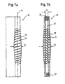
- FIG. 7a an elastic element according to a sixth embodiment is shown.
- Fig. 7b is a sectional view of the elastic element Fig. 7a ,
- the elastic member 35 according to the sixth embodiment differs from that according to the fifth embodiment in that the outer diameter D2 of the elastic member 35 is not constant but varies over the length L 'de of the elastic member 35.
- the outer diameter D2 varies in such a way that, viewed from the free ends, it increases towards the middle of the elastic element 35.
- the flexural rigidity of the elastic member 35 which increases with increasing outer diameter of the elastic member, varies. On the outer diameter of the elastic element can thus be set specifically a specific location-dependent flexural rigidity.
- the elastic member 35 has adjacent each of its two free ends a portion having a predetermined length extending internal thread 36, 36 ', a continuous coaxial bore 37 having an inner diameter D1 and two recesses 38 and 39 in the mold a coil spring through which a double helical spring is formed.
- the elastic element may include more than two coil springs, wherein the turns of a coil spring each extend between the turns of the other coil springs.
- a bore extending over the entire length of the elastic element is provided whose diameter is smaller than the outer diameter of the cylindrical projection 16.
- the fourth to sixth embodiments have each been described so that the flexural rigidity of the elastic member over the length L of the double helical spring increases from the free ends toward the center of the elastic member.
- the pitch ⁇ of the two recesses, the outer diameter D2 of the elastic Element and the inner diameter D1 of the coaxial bore the flexural rigidity with any other location dependence over the length L of the double helical spring or the length L 'of the elastic element can be adjusted.
- the elastic member 51 part of an elastic rod-shaped element 50.
- the elastic rod-shaped element 50 is composed of the spring element 1 and two cylindrical bar sections 51, 51 ', each having at their end a non-illustrated cylindrical projection with an external thread , which cooperates with an internal thread 5 and 5 'of the spring element 1, respectively.
- the rod sections 51, 51 'and the spring element 1 in this embodiment have substantially the same outer diameter.
- the length of the rod sections 51, 51 'and the spring element 1 are independently selectable with regard to a desired application.
- the elastic rod-shaped element 50 serves, for example, for connecting pedicle screws to the spinal column.
- the thus formed rod-shaped element 30 absorbs by the elastic properties of the spring element 1 to a predetermined extent compression, extension, bending and torsional forces.
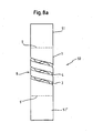
- Fig. 8b shows a second example of the elastic element 1.
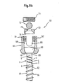
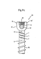
- the elastic element 1 is here Component of a bone anchoring element, which is designed as a polyaxial bone screw 60.
- the polyaxial bone screw 60 has a screw element 61, which consists of the elastic element 1, a threaded shaft 62 in this embodiment with a tip, not shown, and a screw head 63.
- the threaded shaft 62 has a bone thread 64 for screwing into the bone and a cylindrical, not shown Approach with an external thread, which cooperates with the internal thread 5 of the spring element 1.
- the screw head 63 has a cylindrical portion 65 and, adjacent thereto, like the threaded shaft 62 has a cylindrical projection, not shown, with an external thread, which cooperates with the internal thread 5 'of the spring element 1.
- the screw member 61 is pivotally supported in a receiving part 66 in the unloaded state.
- the receiving part 66 is formed substantially cylindrical and has at its one end an axially symmetrical aligned first bore 67, whose diameter is larger than that of the threaded shaft 62 and smaller than that of the screw head 63. Further, the receiving part 66 has a coaxial second bore 68 which is open on the opposite end of the first bore 67 and whose diameter is so large that the screw member 61 can be passed through the open end with the threaded shaft 62 through the first bore 67, until the screw head 63 abuts the edge of the first bore 67.
- the receiving part 66 has a U-shaped recess 69 extending from the free end in the direction of the first bore 67, through which two free legs 70, 70 'are formed. In a region adjacent to their free end, the legs 70, 70 'on an internal thread, which with a corresponding external thread an internal screw 71 for fixing a rod 72 cooperates.
- a pressure element 73 for fixing the screw head 63 in the receiving part 66 which is formed on its side facing the screw head 63 having a spherical recess 74 whose radius is substantially equal to the radius of the spherical segment-shaped portion of the screw head 63 ,
- the outer diameter of the pressure element 73 is selected such that it is displaceable in the receiving part 66 towards the screw head 63.
- the pressure member 73 further includes a coaxial bore 75 for accessing a recess (not shown) in the screw head 63 for engagement with a screwing tool.
- the screw member 61 In operation, in the internal thread 5 of the elastic element 1 of the threaded shaft 62 is screwed with its cylindrical projection not shown and into the internal thread 5 'of the screw head 63 with its cylindrical neck, not shown, to form the screw member 61. Thereafter, the screw member 61 thus formed with the threaded shaft 62 is first inserted through the second bore 68 in the receiving part 66 until the screw head 63 abuts the edge of the first bore 67. Subsequently, the pressure element 73 is introduced with the spherical recess ahead through the second bore 68 in the receiving part 66. Then, the screw member 61 is screwed into the bone or vertebra.
- the rod 72 is inserted into the receiving part 66 between the two free legs 70, 70 ', the angular position of the receiving part is adjusted relative to the screw member and fixed with the inner screw 71.
- the elastic element movements are made possible around the rest position in a limited way.
- the spring element 1 can absorb bending forces, and tensile and compressive forces. If the elastic element, with its elastic portion formed by the coil springs, does not protrude beyond the bone surface, the screw element 61 can nevertheless yield somewhat during a movement of the bone or vertebra. This prevents unfavorable voltages from occurring.
- the polyaxial screw is not limited to the above-described embodiment, but may be any other polyaxial screw having a three-piece screw member as described above.
- the rod fixation is not on the in Fig. 8b shown limited internal screw, but it may additionally be provided an outer nut, or any known type of rod fixing can be used.
- a bone anchoring element is shown, which is designed as a monoaxial screw 80.
- the screw head is formed as a receiving part 81.
- a U-shaped recess 83 is provided adjacent to the first free end of the receiving part 81.
- the free legs 84, 84 'formed by the U-shaped recess have on their inside an internal thread into which the external thread of an internal screw 85 engages.
- the rod 82 is assembled in State of the monoaxial screw between the bottom of the U-shaped recess 83 and the inner screw 85 is clamped.
- a non-illustrated cylindrical projection is provided with an external thread, which engages in the adjacent to the first end of the elastic member 1 internal thread 5.
- the monoaxial screw Adjacent to the first end of the elastic portion 1 opposite end, the monoaxial screw has a threaded shaft 86 which is formed as the above-described threaded shaft 62 of the polyaxial bone screw 60 and with a non-illustrated cylindrical projection with an external thread in the internal thread 5 'of the elastic member 1 engages.
- the threaded shaft 86 and the receiving part are screwed into the two internal threads 5, 5 'of the elastic element 1. Subsequently, the monoaxial screw 80 is screwed into the bone or the vertebra. Then, the U-shaped recess 83 is aligned and the rod 82 is inserted. Finally, the rod 82 is fixed with the inner screw 85.
- FIG. 8d As another example of the elastic member 1 is shown in FIG Fig. 8d to see a plan view of a connecting element 90, which consists of a rod-shaped portion 91, a spring element 1 and a plate 92.
- the rod-shaped portion 91 has a cylindrical projection, not shown, with an external thread for screwing into the adjacent to the one end of the spring element 1 internal thread 5.
- the plate 92 has a cylindrical projection, not shown, with an external thread to Screwing into the adjacent to the other end of the spring element 1 internal thread 5 'on.
- the plate consists of two circular in plan view sections 93, 93 ', which are interconnected via a web portion 94.
- the width B of the web portion 94 is smaller than the diameter D of the circular portions 93, 93 '.
- Coaxial with the circular sections are provided two bores 95, 95 'for countersunk screws through the plate.
- the first side 96 of the plate has a convex curvature while the second side 97 of the plate has a concave curvature for abutment of this side of a bone. Due to the different radii of curvature of the two sides 96, 97 of the plate 92, the plate 92 tapers to the lateral edges 98, 98 'out. This allows the plate to be stable and at the same time space-saving.
- the rod-shaped element 50, the polyaxial bone screw 60, the monoaxial screw 80 and the connecting element 90 has been described so that the elastic element 1 is formed as a separate part and is screwed to the other parts.
- the elastic member is formed as a portion of a one-piece screw member, a one-piece monoaxial screw and a one-piece connecting member having a rod and a plate portion. It is also possible to smoothly connect the elastic member to the other members such as the threaded shaft 62, the rod portion 51, 51 ', the plate 92, or the screw head 63.
- a stabilization device 100 is shown for the spine, wherein two bone anchoring elements 101, 101 'and an elastic rod-shaped element 103 connecting them is provided.
- the screw elements 102, 102 'of the bone anchoring elements 101 and 101' and the elastic rod-shaped element 103 each have an elastic element 1 according to the invention.
- the two screw elements 102, 102 ' are screwed into vertebrae 103, 103', so that a dynamic stabilization is produced between these vertebrae via the stabilization device 100.
- the stabilizing device need not necessarily include bone anchoring elements with a resilient element and a rod-shaped element with the resilient element. Depending on the field of application, it is also possible to provide only a rod-shaped element with an elastic element and bone anchoring elements without an elastic element with rigid screw elements.
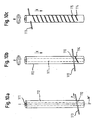
- an elastic element 1 by means of wire EDM is in a solid cylinder from a body-true material, such as. As titanium, perpendicular to the center axis of the cylinder through the entire cylinder extending first bore 110 is generated. Then, a second bore 111 is formed coaxially with the center axis of the cylinder over its entire length, so that a hollow cylinder 112 is formed. The order of forming the first and second bores is arbitrary and may be reversed. Subsequently, a wire 113 is made through the first wire eroding hole 110.
- Fig. 10a indicates this process step by an arrow P.
- wire EDM 113 is performed while the hollow cylinder 112 is displaced along the center axis in the direction X at a constant feed rate relative to the wire and simultaneously rotated at a constant angular velocity about its center axis.
- the rotation is in Fig. 10b indicated by an arrow D. It depends solely on a relative movement between the wire and the hollow cylinder. So either the wire can be fixed in space and the hollow cylinder to be moved or vice versa.
- Fig. 10c shows the elastic element just before the end of the wire EDM step. After the recesses are formed in the axial direction over a predetermined length, the feed and the rotation of the hollow cylinder is stopped.
- a semi-circular outlet 120, 120 'formed As in Fig. 11 shown at the beginning of the wire erosion and at the end of the wire erosion in each case a semi-circular outlet 120, 120 'formed.
- the shape of the spout 120 or 120 'does not necessarily have the shape of a semicircle, but may also have any other arbitrary shape, such as that of another circular section, through the load spikes in the material at the transition from the flexible section to the fixed section during operation being held.
- the advantage of the wire EDM method described above for producing the spout is that the outlets of the two coil springs can each be made in a single operation, an additional switch between the axes of the wire EDM machine is not in this embodiment compared to the production of a single coil spring necessary.
- an internal thread 5, 5 ' is formed in the two end sections of the coaxial bore adjoining the two ends along the center axis.
- the elastic element 1 can also be produced by means of milling. This is again based on a cylinder with a predetermined outer diameter of a biocompatible material, such as titanium, and milled with a thin disc cutter along a first helix, the main axis collinear to the main axis of the cylinder is a first recess. Then, in a second step, a further recess is formed along a second helix whose turns run between the turns of the first helix. Subsequently, along the main axis of the cylinder over the entire length of the cylinder, a bore is formed such that the recesses in this bore lead.
- a biocompatible material such as titanium
- the outlet of the spiral at the transition between the spiral portion and the end portion of the elastic member has a great influence on the stability of the elastic element 1. Therefore, with a router bit the spout of the spiral at both ends of the spiral is post-processed such that the sharp edge the inside of the hole is removed. For this purpose, the spout is milled with an end mill at an angle tangential to the spiral contour. Subsequently, the component is deburred inside and outside.
- an internal thread 5, 5 ' is respectively formed in the two end sections of the coaxial bore along the center axis.
- a cylindrical projection with an external thread is formed by turning.
- the diameter of the bore 111 must be smaller than the diameter of the cylindrical neck.
- the spring element according to the second and third embodiments is produced without a through hole 111.
Description
Die Erfindung betrifft eine Stabilisierungseinrichtung für Knochen oder Wirbel mit einem elastischen ElementThe invention relates to a stabilizing device for bones or vertebrae with an elastic element
Zur Fixierung von Knochenfrakturen oder zur Stabilisierung der Wirbelsäule sind Fixations- und Stabilisierungseinrichtungen bekannt, die aus wenigstens zwei im Knochen bzw. Wirbel verankerten und über eine Platte oder über einem Stab verbundenen Knochenschrauben bestehen. Derartige starre Systeme erlauben keine Bewegung der relativ zueinander fixierten Knochenteile oder Wirbel.For fixation of bone fractures or for stabilization of the spine fixation and stabilization devices are known, which consist of at least two anchored in the bone or vertebrae and connected via a plate or a rod bone screws. Such rigid systems do not allow movement of the relatively fixed bone parts or vertebrae.
Für bestimmte Indikationen ist jedoch eine dynamische Stabilisierung wünschenswert, bei der die zu stabilisierenden Knochenteile und Wirbel eine kontrollierte begrenzte Bewegung zu einander ausführen können. Eine Möglichkeit für die Realisierung der dynamischen Stabilisierungseinrichtung besteht in der Verwendung eines elastischen Elementes anstelle eines die Knochenverankerungselemente verbindenden starren Stabes.However, for certain indications dynamic stabilization is desirable in which the bone parts and vertebrae to be stabilized can perform a controlled limited movement towards each other. One possibility for the realization of the dynamic stabilization device is the use of an elastic element instead of a rigid rod connecting the bone anchoring elements.
Aus der
Aus der
Die altere An-meldung
Es ist Aufgabe der Erfindung, eine Stabilisierungsvorrichtug für Knochen oder Wirbel mit einem elastischen Element bereit zu stellen, das eine hohe Biegesteifigkeit bei geringer Baulänge hat, sowie leicht zu handhaben ist bei gleichzeitig hoher Sicherheit im Einsatz, und welches mit anderen Elementen in möglichst vielfältiger Weise zu einer dynamischen Stabilisierungseinrichtung für Wirbel oder Knochen kombiniert werden kann.It is an object of the invention to provide a Stabilisierungsvorrichtug for bones or vertebrae with an em elastic n element which has a high rigidity with small overall length, as well as easy to handle, is at the same time, high safety in use and which with other elements in as various ways to a dynamic stabilizing device for vertebrae or bone can be combined.
Die Aufgabe wird gelöst durch eine Stabilisierungsvorrichtung nach dem Patentanspruch 1.The object is achieved by an e stabilization device according to
Weiterbildungen der Erfindung sind in den Unteransprüchen angegeben.Further developments of the invention are specified in the subclaims.
Die Erfindung weist den Vorteil auf, dass ein elastisches Element zugleich kompakt und mit hoher Biegesteifigkeit ausgebildet ist. Dies ist insbesondere für Anwendungen an der Wirbelsäule und dort insbesondere an der Halswirbelsäule von Bedeutung, wo der zu Verfügung stehende Platz im Vergleich zu Anwendungen an der Lendenwirbelsäule deutlich geringer ist.The invention has the advantage that an elastic element is formed at the same time compact and with high bending stiffness. This is particularly important for applications on the spinal column and there especially on the cervical spine, where the available space is significantly lower compared to applications on the lumbar spine.
Ferner weist die Erfindung den Vorteil auf, dass ein elastisches Element wahlweise mit starren stabförmigen Elementen verschiedener Länge zu einem elastischen stabförmigen Element kombinierbar ist oder mit verschiedenen Schäften und/oder Köpfen zu einer Knochenschraube mit elastischen Eigenschaften kombinierbar ist. Das elastische stabförmige Element bzw. die Knochenschraube weisen dann in Abhängigkeit von dem verwendetem elastischen Element vorgegebene elastische Eigenschaften wie eine bestimmte Kompressions- und Extensionsfähigkeit in axialer Richtung, sowie eine bestimmte Biege- und Torsionssteifigkeit auf.Furthermore, the invention has the advantage that an elastic element can optionally be combined with rigid rod-shaped elements of different lengths to form an elastic rod-shaped element or combined with different shafts and / or heads to form a bone screw with elastic properties. The elastic rod-shaped element or the bone screw then have, depending on the elastic element used predetermined elastic properties such as a certain compression and extension ability in the axial direction, and a certain bending and torsional rigidity.
Insbesondere kann das elastisches Element mit stabförmigen Bauteilen verschiedener Dicke oder mit in der Wirbelsäulenund/oder Unfallchirurgie zu verwendenden Platten unterschiedlicher Form und Länge verbunden werden.In particular, the elastic element can be connected with rod-shaped components of different thickness or with plates of different shape and length to be used in spinal and / or trauma surgery.
Weitere Merkmale und Zweckmäßigkeiten ergeben sich aus der Beschreibung von Ausführungsbeispielen anhand der Figuren.Further features and expediencies will become apparent from the description of embodiments with reference to FIGS.
Von den Figuren zeigen:
- Fig. 1
- ein elastisches Element mit einer Doppelschraubenfeder nach einer ersten Ausführungsform der Erfindung;
- Fig. 2
- eine schematische Darstellung der Doppelschraubenfeder des elastischen Elements aus
Fig. 1 einmal als Ganzes (Fig. 2a ) und in Explosionsdarstellung (Fig. 2b ); - Fig. 3
- ein elastisches Element mit einer Doppelschraubenfeder nach einer zweiten Ausführungsform der Erfindung;
- Fig. 4a, 4b
- ein elastisches Element mit einer Doppelschraubenfeder nach einer dritten Ausführungsform, einmal als Ganzes (
Fig. 4a ) und einmal in Explosionsdarstellung (Fig. 4b ); - Fig. 5a
- ein elastisches Element mit einer Doppelschraubenfeder nach einer vierten Ausführungsform der Erfindung;
- Fig. 5b
- eine Schnittdarstellung des elastischen Elements aus
Fig. 5a ; - Fig. 6
- eine Schnittdarstellung eines elastischen Elements mit einer Doppelschraubenfeder nach einer fünften Ausführungsform der Erfindung;
- Fig. 7a
- ein elastisches Element mit einer Doppelschraubenfeder nach einer sechsten Ausführungsform der Erfindung;
- Fig. 7b
- eine Schnittdarstellung des elastischen Elements aus
Fig. 7a ; - Fig. 8a
- ein stabförmiges Element mit dem erfindungsgemäßen elastischen Element;
- Fig. 8b
- eine teilgeschnittene Explosionsdarstellung einer Polyxialknochenschraube mit dem elastischen Element;
- Fig. 8c
- eine teilgeschnittene Darstellung einer Monoaxialschraube mit dem elastischen Element;
- Fig. 8d
- eine Ansicht von oben auf einen aus einer Platte, dem elastischen Element und einen Stababschnitt bestehenden Teil einer Stabilisierungsvorrichtung für Knochen oder Wirbel, sowie einen Querschnitt durch die Platte;
- Fig. 9
- eine erfindungsgemäß Stabilisierungseinrichtung für die Wirbelsäule;
- Fig. 10a-c
- Schritte einer Ausführungsform eines Verfahrens zur Herstellung des elastischen Elementes; und
- Fig. 11
- ein erfindungsgemäßes elastisches Element mit einem halbkreisförmigen Auslauf an beiden Enden der Doppelschraubenfeder.
- Fig. 1
- an elastic member having a double helical spring according to a first embodiment of the invention;
- Fig. 2
- a schematic representation of the double helical spring of the elastic element
Fig. 1 once as a whole (Fig. 2a ) and in exploded view (Fig. 2b ); - Fig. 3
- an elastic member with a double helical spring according to a second embodiment of the invention ;
- Fig. 4a, 4b
- an elastic element with a double helical spring according to a third embodiment, once as a whole (
Fig. 4a ) and once in exploded view (Fig. 4b ); - Fig. 5a
- an elastic member having a double helical spring according to a fourth embodiment of the invention;
- Fig. 5b
- a sectional view of the elastic element
Fig. 5a ; - Fig. 6
- a sectional view of an elastic member with a double helical spring according to a fifth embodiment of the invention;
- Fig. 7a
- an elastic member having a double helical spring according to a sixth embodiment of the invention;
- Fig. 7b
- a sectional view of the elastic element
Fig. 7a ; - Fig. 8a
- a rod-shaped element with the elastic element according to the invention;
- Fig. 8b
- a partially sectioned exploded view of a polyxal bone screw with the elastic member;
- Fig. 8c
- a partially sectioned view of a monoaxial screw with the elastic element;
- Fig. 8d
- a top view of a consisting of a plate, the elastic member and a rod portion part of a stabilizing device for bone or vertebrae, and a cross section through the plate;
- Fig. 9
- an inventive stabilization device for the spine;
- Fig. 10a-c
- Steps of an embodiment of a method for producing the elastic element; and
- Fig. 11
- an inventive elastic element with a semicircular spout at both ends of the double helical spring.
DieThe
In
Das elastische Element 1 ist als hohlzylindrisches Element mit einer durchgehenden koaxialen Bohrung 2 und einer spiralförmig mit einer vorbestimmten Steigung und über eine vorbestimmte Länge in Richtung der Zylinderachse in der Wandung verlaufenden ersten Ausnehmung 3, die in radialer Richtung in die Bohrung 2 mündet, ausgebildet. Weiter ist spiralförmig mit der gleichen Steigung wie die erste Ausnehmung 3 über die gleiche Länge in Richtung der Zylinderachse M in der Wandung zwischen den Windungen der ersten Ausnehmung 3 eine zweite Ausnehmung 4 vorgesehen, die in radialer Richtung in die Bohrung 2 mündet. Dadurch ist eine Doppelschraubenfeder aus zwei Schraubenfedern gebildet, wobei die Windungen der einen Schraubenfeder zwischen den Windungen der zweiten Schraubenfeder verlaufen. Bevorzugt sind die Windungen der einen Schraubenfeder relativ zu den Windungen der anderen Schraubenfeder um ihre gemeinsame Mittenachse um 180° gedreht, sodass sich die erste und die zweite Ausnehmung genau gegenüberliegen.The
Die Länge L der spiralförmigen Ausnehmungen 3, 4 in Richtung der Zylinderachse, die Höhe H der Ausnehmungen, die Steigung α der Schraubenlinien, entlang denen die Ausnehmungen 3, 4 ausgebildet sind, und der Durchmesser D1 der koaxialen Bohrung 2 sind so gewählt, dass eine gewünschte Steifigkeit des elastischen Elements gegenüber axialen Kräften Fax, Biegekräften FB und Torsionskräften FT, die auf das elastische Element wirken, gegeben ist. Angrenzend an seine beiden freien Enden weist das elastische Element 1 jeweils einen Abschnitt mit einem sich über eine vorbestimmte Länge erstreckenden Innengewinde 5, 5' auf. Die Innengewindeabschnitte überlappen in axialer Richtung nicht mit dem Abschnitt, in dem die Ausnehmungen in der Wandung ausgebildet sind. Der Außendurchmesser des elastischen Elements 1 ist der jeweiligen Anwendung entsprechend gewählt. Das elastische Element ist aus einem körperfreundlichen Material wie z.B. Titan ausgebildet.The length L of the spiral recesses 3, 4 in the direction of the cylinder axis, the height H of the recesses, the pitch α of the helical lines, along which the
Die Doppelschraubenfeder 6 setzt sich zusammen aus zwei Schraubenfedern 7 und 8. Die beiden Schraubenfedern 7 und 8 sind identisch ausgebildet und besitzen insbesondere eine identische Steigung α, jedoch ist die erste Schraubenfeder 7 in der Doppelschraubenfeder 6 gegenüber der zweiten Schraubenfeder 8 um ihre gemeinsame Mittenachse um 180° gedreht. Die Windungen der ersten Schraubenfeder 7 verlaufen bei der Doppelschraubenfeder 6 daher in der Mitte zwischen den Windungen der zweiten Schraubenfeder 8 und umgekehrt.The
Bei einer vorgegebenen Baulänge eines elastischen Elementes ist die Steigung der Schraubenfeder dadurch begrenzt, dass mindestens eine ganze Windung vorhanden sein muss, um gute Elastizitätseigenschaften zu erhalten. Bei einer Doppelschraubenfeder ist für jeden der Schraubenfedern weniger als eine ganze Windung notwendig, um gute Elastizitätseigenschaften zu erhalten. Daher kann bei gleicher Baulänge die Steigung der Schraubenfeder im Vergleich zu einer Einfachschraubenfeder erhöht werden. Eine Erhöhung der Steigung der Schraubenfeder ergibt bei gleicher Baulänge und gleichen sonstigen Eigenschaften eine Erhöhung der Biegesteifigkeit. Daher ist es mit einer Doppelschraubenfeder gegenüber einer Einfachschraubenfeder möglich bei gleichen Abmessungen eine höhere Biegesteifigkeit zu erreichen.For a given length of an elastic element, the pitch of the coil spring is limited by the fact that at least one entire turn must be present in order to obtain good elasticity properties. With a twin coil spring, less than a full turn is required for each of the coil springs to obtain good elasticity properties. Therefore, with the same length, the slope of the Helical spring can be increased compared to a single helical spring. An increase in the pitch of the coil spring results in the same length and the same other properties increase the flexural rigidity. Therefore, it is possible with a twin helical spring compared to a single helical spring with the same dimensions to achieve a higher bending stiffness.
In
Das elastische Element 11 nach einer zweiten Ausführungsform unterscheidet sich von dem elastischen Element 1 nach einer ersten Ausführungsform dadurch, dass anstelle einer sich von dem ersten bis zu dem zweiten Ende 17' des elastischen Elementes erstreckenden Bohrung 2 eine an das erste Ende 17 des elastischen Elements angrenzende Sackbohrung 12 vorgesehen ist. Die Sackbohrung erstreckt sich dabei über die gesamte Länge L der Doppelschraubenfeder, die wie bei der ersten Ausführungsform durch eine erste und eine zweite Ausnehmung 13 und 14 in der Wandung eines hohlzylindrischen Abschnittes gebildet wird. An das erste Ende 17 angrenzend ist in der Sackbohrung ein Innengewinde 15 vorgesehen. An dem dem ersten Ende 17 gegenüberliegenden zweiten Ende 17' weist das elastische Element einen zylinderförmigen Ansatz 16 mit einem Außengewinde auf.The
In
Das elastische Element 20 nach der dritten Ausführungsform unterscheidet sich dadurch von den anderen Ausführungsformen, dass keine Bohrung koaxial zur Mittenachse M des elastischen Elementes 20 vorgesehen ist. Des weiteren ist sowohl an das erste Ende 22, als auch an das zweite Ende 22' angrenzend ein zylindrischer Ansatz 23, 23' mit einem Außengewinde vorgesehen. Wie bei den zuvor beschriebenen Ausführungsformen werden durch zwei Ausnehmungen 24, 25 zwei Schraubenfedern 26, 27 gebildet .The
In
Das elastische Element 30 nach der vierten Ausführungsform unterscheidet sich von dem nach der ersten Ausführungsform dadurch, dass die Steigung α der die Doppelschraubenfeder bildenden Ausnehmungen 31, 32 nicht konstant ist, sondern über die Länge L der Doppelschraubenfeder des elastischen Elements 30 variiert. Dabei variiert die Steigung α derart, dass der Abstand ΔL der Ausnehmungen 31, 32 von den freien Enden des elastischen Elements 30 aus gesehen zur Mitte hin zunimmt. Dementsprechend variiert auch die Biegesteifigkeit des elastische Elements 30, die mit zunehmendem Abstand ΔL der Ausnehmungen 31, 32 zunimmt. Über die Steigung der Ausnehmungen entlang der Mittenachse des elastischen Elements kann somit gezielt eine bestimmte ortsabhängige Biegesteifigkeit eingestellt werden.The
Wie die erste Ausführungsform weist das elastische Element 30 nach der vierten Ausführungsform angrenzend an seine beiden freien Enden jeweils einen Abschnitt mit einem sich über eine vorbestimmte Länge erstreckenden Innengewinde 33, 33' und eine durchgehende koaxiale Bohrung 34 mit einem Innendurchmesser D1 auf.Like the first embodiment, the
Das elastische Element 40 nach der fünften Ausführungsform unterscheidet sich von dem elastischen Element 30 nach der vierten Ausführungsform dadurch, dass der Innendurchmesser D1 der durchgehenden koaxialen Bohrung 42 nicht konstant ist, sondern über die Länge L' des elastischen Elements 40 variiert. Der Innendurchmesser D1 der Bohrung 42 variiert dabei derart, dass er von den freien Enden aus gesehen zur Mitte des elastischen Elements 40 hin abnimmt. Dementsprechend variiert auch die Biegesteifigkeit des elastischen Elements 40, die mit abnehmendem Innendurchmesser D1 zunimmt. Über den Innendurchmesser der koaxialen Bohrung kann somit gezielt eine bestimmte ortsabhängige Biegesteifigkeit des elastischen Elements 40 eingestellt werden.The
Wie die vierte Ausführungsform weist das elastische Element 40 angrenzend an seine beiden freien Enden jeweils einen Abschnitt mit einem sich über eine vorbestimmte Länge erstreckenden Innengewinde 41, 41'.Like the fourth embodiment, the
In
Das elastische Element 35 nach der sechsten Ausführungsform unterscheidet sich von dem nach der fünften Ausführungsform dadurch, dass der Außendurchmesser D2 des elastischen Elements 35 nicht konstant ist, sondern über die Länge L' de des elastischen Elements 35 variiert. Dabei variiert der Außendurchmesser D2 derart, dass er von den freien Enden aus gesehen zur Mitte des elastischen Elements 35 hin zunimmt. Dementsprechend variiert auch die Biegesteifigkeit des elastischen Elements 35, die mit zunehmendem Außendurchmesser des elastischen Elements zunimmt. Über den Außendurchmesser des elastischen Elements kann somit gezielt eine bestimmte ortsabhängige Biegesteifigkeit eingestellt werden.The
Wie die vierte Ausführungsform weist das elastische Element 35 angrenzend an seine beiden freien Enden jeweils einen Abschnitt mit einem sich über eine vorbestimmte Länge erstreckenden Innengewinde 36, 36', eine durchgehende koaxiale Bohrung 37 mit einem Innendurchmesser D1 sowie zwei Ausnehmungen 38 und 39 in der Form einer Schraubenfeder auf, durch die eine Doppelschraubenfeder gebildet wird.Like the fourth embodiment, the
Abwandlungen des elastischen Elementes von den zuvor beschriebenen Ausführungsformen sind möglich.Modifications of the elastic member of the above-described embodiments are possible.
So kann das elastische Element mehr als zwei Schraubenfedern beinhalten, wobei die Windungen einer Schraubenfeder jeweils zwischen den Windungen der anderen Schraubenfedern verlaufen.Thus, the elastic element may include more than two coil springs, wherein the turns of a coil spring each extend between the turns of the other coil springs.
In einer weiteren Abwandlung der zweiten Ausführungsform ist anstelle der Sackbohrung 12 eine sich über die gesamte Länge des elastischen Elementes erstreckende Bohrung vorgesehen, deren Durchmesser kleiner als der Außendurchmesser des zylindrischen Ansatzes 16 ist.In a further modification of the second embodiment, instead of the blind bore 12, a bore extending over the entire length of the elastic element is provided whose diameter is smaller than the outer diameter of the
Die vierte bis sechste Ausführungsform wurde jeweils so beschrieben, dass die Biegesteifigkeit des elastische Elements über die Länge L der Doppelschraubenfeder von den freien Enden aus gesehen zur Mitte des elastischen Elements hin zunimmt. Jedoch kann durch entsprechende Gestaltung der Steigung α der beiden Ausnehmungen, des Außendurchmessers D2 des elastischen Elements und des Innendurchmesser D1 der koaxialen Bohrung die Biegesteifigkeit mit einer beliebigen andere Ortsabhängigkeit über die Länge L der Doppelschraubenfeder bzw. die Lange L' des elastischen Elements eingestellt werden.The fourth to sixth embodiments have each been described so that the flexural rigidity of the elastic member over the length L of the double helical spring increases from the free ends toward the center of the elastic member. However, by appropriate design of the pitch α of the two recesses, the outer diameter D2 of the elastic Element and the inner diameter D1 of the coaxial bore, the flexural rigidity with any other location dependence over the length L of the double helical spring or the length L 'of the elastic element can be adjusted.
Alle Ausführungsformen wurden so beschrieben, dass das elastische Element die Form eines Zylinders bzw. Hohlzylinders aufweist, jedoch kann die äußere Form auch von der exakten Form eines Zylinders abweichen und z.B. eine ovale Querschnittsfläche haben oder tailliert ausgebildet sein. Das elastische Element hat damit eine richtungsabhängige Biegeelastizität.All embodiments have been described as having the elastic member in the form of a cylinder, but the outer shape may also deviate from the exact shape of a cylinder, e.g. have an oval cross-sectional area or be formed waisted. The elastic element thus has a direction-dependent bending elasticity.
In einem ersten, in
Die Polyaxialknochenschraube 60 weist ein Schraubenelement 61 auf, welches aus dem elastischen Element 1, einem Gewindeschaft 62 in diesem Ausführungsbeispiel mit einer nicht dargestellten Spitze und einem Schraubenkopf 63 besteht.Der Gewindeschaft 62 weist ein Knochengewinde 64 zum Einschrauben in den Knochen und einen nicht dargestellten zylinderförmigen Ansatz mit einem Außengewinde auf, das mit dem Innengewinde 5 des Federelementes 1 zusammenwirkt. Der Schraubenkopf 63 weist einen zylinderförmigen Abschnitt 65 und daran angrenzend wie der Gewindeschaft 62 einen nicht dargestellten zylinderförmigen Ansatz mit einem Außengewinde auf, das mit dem Innengewinde 5' des Federelementes 1 zusammenwirkt.The
Das Schraubenelement 61 ist in einem Aufnahmeteil 66 in unbelastetem Zustand schwenkbar gehalten. Das Aufnahmeteil 66 ist im wesentlichen zylindrisch ausgebildet und weist an seinem einen Ende eine axialsymmetrisch ausgerichtete erste Bohrung 67 auf, deren Durchmesser größer als der des Gewindeschafts 62 und kleiner als der des Schraubenkopfs 63 ist. Ferner weist das Aufnahmeteil 66 eine koaxiale zweite Bohrung 68 auf, die auf dem der ersten Bohrung 67 gegenüberliegenden Ende offen ist und deren Durchmesser so groß ist, dass das Schraubenelement 61 durch das offene Ende mit dem Gewindeschaft 62 durch die erste Bohrung 67 hindurchführbar ist, bis der Schraubenkopf 63 am Rand der ersten Bohrung 67 anliegt. Das Aufnahmeteil 66 weist eine sich vom freien Ende in Richtung der ersten Bohrung 67 erstreckende U-förmige Ausnehmung 69 auf, durch die zwei freie Schenkel 70, 70' gebildet sind. In einem Bereich angrenzend an ihr freies Ende weisen die Schenkel 70, 70' ein Innengewinde auf, welches mit einem entsprechenden Außengewinde einer Innenschraube 71 zum Fixieren eines Stabs 72 zusammenwirkt.The
Es ist ferner ein Druckelement 73 zum Fixieren des Schraubenkopfs 63 in dem Aufnahmeteil 66 vorgesehen, das so ausgebildet ist, dass es an seiner dem Schraubenkopf 63 zugewandten Seite eine sphärische Ausnehmung 74 aufweist, deren Radius im wesentlichen gleich dem Radius des kugelsegmentförmigenAbschnitts des Schraubenkopfes 63 ist. Der Außendurchmesser des Druckelements 73 ist so gewählt, dass es in dem Aufnahmeteil 66 zu dem Schraubenkopf 63 hin verschiebbar ist. Das Druckelement 73 weist ferner eine koaxiale Bohrung 75 für den Zugriff auf eine nicht dargestellte Ausnehmung in dem Schraubenkopf 63 zum Ineingriffbringen mit einem Einschraubwerkzeug auf.There is further provided a pressure element 73 for fixing the
Im Betrieb wird in das Innengewinde 5 des elastischen Elementes 1 der Gewindeschaft 62 mit seinem nicht dargestellten zylinderförmigen Ansatz und in das Innengewinde 5' der Schraubenkopf 63 mit seinem nicht dargestellten zylinderförmigen Ansatz eingeschraubt, um das Schraubenelement 61 zu bilden. Danach wird das so gebildete Schraubenelement 61 mit dem Gewindeschaft 62 voran durch die zweite Bohrung 68 in das Aufnahmeteil 66 eingeführt, bis der Schraubenkopf 63 am Rand der ersten Bohrung 67 anliegt. Anschließend wird das Druckelement 73 mit der sphärischen Ausnehmung voran durch die zweite Bohrung 68 in das Aufnahmeteil 66 eingeführt. Dann wird das Schraubenelement 61 in den Knochen bzw. Wirbel eingeschraubt. Schließlich wird der Stab 72 in das Aufnahmeteil 66 zwischen die beiden freien Schenkel 70, 70' eingelegt, die Winkelstellung des Aufnahmeteils relativ zu dem Schraubenelement justiert und mit der Innenschraube 71 fixiert. Durch das elastische Element werden Bewegungen um die Ruhelage in begrenzter Weise ermöglicht.In operation, in the
Wenn das elastische Element 1 wenigstens teilweise mit seinem durch die Schraubenfedern gebildeten elastischen Abschnitt über die Knochenoberfläche hervorsteht kann das Federelement 1 Biegekräfte, sowie Zug- und Druckkräfte aufnehmen. Steht das elastische Element mit seinem durch die Schraubenfedern gebildeten elastischen Abschnitt nicht mehr über die Knochenoberfläche hervor, kann das Schraubenelement 61 trotzdem bei einer Bewegung des Knochens bzw. Wirbels etwas nachgeben. Damit wird verhindert, dass ungünstige Spannungen auftreten.If the
Die Polyaxialschraube ist nicht auf die zuvor beschriebene Ausführungsform beschränkt, sondern kann auch jede beliebige andere Polyaxialschraube mit einem wie oben beschriebenen dreiteiligen Schraubenelement sein.The polyaxial screw is not limited to the above-described embodiment, but may be any other polyaxial screw having a three-piece screw member as described above.
Die Stabfixierung ist nicht auf die in
Als ein drittes Beispiel des elastischen Elements ist in
Bei der Monoaxialschraube 80 ist der Schraubenkopf als Aufnahmeteil 81 ausgebildet. Zur Aufnahme des Stabes 82 ist an das erste freie Ende des Aufnahmeteils 81 angrenzend eine U-förmige Ausnehmung 83 vorgesehen. Die durch die U-förmige Ausnehmung gebildeten freien Schenkel 84, 84'.weisen auf ihrer Innenseite ein Innengewinde auf, in das das Aussengewinde einer Innenschraube 85 eingreift. Der Stab 82 wird im zusammengebauten Zustand der Monoaxialschraube zwischen dem Boden der U-förmigen Ausnehmung 83 und der Innenschraube 85 festgeklemmt. Angrenzend an ein dem ersten freien Ende gegenüberliegenden zweiten Ende des Aufnahmeteils 81 ist ein nicht dargestellter zylindrischer Ansatz mit einem Außengewinde vorgesehen, der in das an das erste Ende des elastischen Elementes 1 angrenzende Innengewinde 5 eingreift. Angrenzend an das dem ersten Ende des elastischen Abschnittes 1 gegenüberliegende Ende weist die Monoaxialschraube einen Gewindeschaft 86 auf, der wie der oben beschriebene Gewindeschaft 62 der Polyaxialknochenschraube 60 ausgebildet ist und mit einem nicht dargestellten zylindrischen Ansatz mit einem Außengewinde in das Innengewinde 5' des elastischen Elements 1 eingreift.In the
Im Betrieb werden zunächst der Gewindeschaft 86 und das Aufnahmeteil in die beiden Innengewinde 5, 5' des elastischen Elements 1 eingeschraubt. Anschließend wird die Monoaxialschraube 80 in den Knochen oder den Wirbel eingeschraubt. Dann wird die U-förmige Ausnehmung 83 ausgerichtet und der Stab 82 eingelegt. Schließlich wird der Stab 82 mit der Innenschraube 85 fixiert.In operation, first the threaded
Als weiteres Beispiel für das elastische Element 1 ist in
Der stabförmige Abschnitt 91 weist einen nicht dargestellten zylindrischen Ansatz mit einem Außengewinde zum Einschrauben in das an das eine Ende des Federelementes 1 angrenzende Innengewinde 5 auf. Ebenso weist die Platte 92 einen nicht dargestellten zylindrischen Ansatz mit einem Außengewinde zum Einschrauben in das an das andere Ende des Federelementes 1 angrenzende Innengewinde 5' auf.The rod-shaped
Die Platte besteht aus zwei in der Draufsicht kreisförmigen Abschnitten 93, 93', die über einen Stegabschnitt 94 miteinander verbunden sind. Die Breite B des Stegabschnittes 94 ist geringer als der Durchmesser D der kreisförmigen Abschnitte 93, 93'. Koaxial zu den kreisförmigen Abschnitten sind zwei Bohrungen 95, 95' für Senkschrauben durch die Platte vorgesehen.The plate consists of two circular in
Wie in
Abwandlungen der mit den
In
Durch die Mehrteiligkeit des elastischen stabförmigen Elementes und der Schraubenelemente ist es möglich, durch die Kombination von nur wenigen Grundelementen Stabilisierungsvorrichtungen 100 mit verschiedenen Eigenschaften zu erhalten. Die Stabilisierungsvorrichtung muß nicht notwendigerweise Knochenverankerungselemente mit einem elastischen Element und ein stabförmiges Element mit dem elastischen Element beinhalten. Je nach Anwendungsgebiet ist es auch möglich, nur ein stabförmiges Element mit einem elastischem Element und Knochenverankerungselemente ohne elastisches Element mit starren Schraubenelementen vorzusehen.Due to the multi-part of the elastic rod-shaped element and the screw elements, it is possible to obtain by the combination of only a few basic
Die Herstellung eines elastischen Elementes 1 nach der ersten Ausführungsform ist in den
Zur Herstellung eines elastischen Elements 1 mittels Drahterodieren wird in einem Vollzylinder aus einem körpervertreglichen Material, wie z. B. Titan, senkrecht durch die Mittenachse des Zylinders eine sich durch den gesamten Zylinder erstreckende erste Bohrung 110 erzeugt. Dann wird eine zweite Bohrung 111 koaxial zu der Mittenachse des Zylinders über dessen gesamte Länge gebildet, sodass ein Hohlzylinder 112 entsteht. Die Reihenfolge des Bildens der ersten und der zweiten Bohrung ist beliebig und kann auch umgekehrt sein. Anschließend wird durch die erste Bohrung 110 zum Drahterodieren ein Draht 113 durchgeführt.
Im nächsten Schritt wird mit dem Draht 113 Drahterodieren durchgeführt, während der Hohlzylinder 112 entlang der Mittenachse in Richtung X mit konstanter Vorschubgeschwindigkeit relativ zum Draht verschoben und gleichzeitig mit konstanter Winkelgeschwindigkeit um seine Mittenachse gedreht wird. Die Drehung ist in
Wie in
Der Vorteil des oben beschriebenen Verfahrens mit Drahterodieren liegt für die Erzeugung des Auslaufs darin, dass die Ausläufe der beiden Schraubenfedern jeweils in einem gemeinsamen Arbeitsschritt hergestellt werden können, ein zusätzliches Umschalten zwischen den Achsen der Drahterodiermaschine ist bei dieser Ausführungsform im Vergleich zur Herstellung einer Einfachschraubenfeder nicht notwendig.The advantage of the wire EDM method described above for producing the spout is that the outlets of the two coil springs can each be made in a single operation, an additional switch between the axes of the wire EDM machine is not in this embodiment compared to the production of a single coil spring necessary.
Schließlich wird in den zwei an die beiden Enden angrenzenden Endabschnitten der koaxialen Bohrung entlang der Mittenachse jeweils ein Innengewinde 5, 5' gebildet.Finally, in each case an
Alternativ kann das elastische Element 1 auch mittels Fräsen hergestellt werde. Dabei geht man wiederum von einem Zylinder mit einem vorbestimmten Außendurchmesser aus einem körperverträglichen Material, wie z.B. Titan, aus und fräst mit einem dünnen Scheibenfräser entlang einer ersten Schraubenlinie, deren Hauptachse kollinear zu der Hauptachse des Zylinders ist eine erste Ausnehmung. Dann wird in einem zweiten Schritt entlang einer zweiten Schraubenlinie, deren Windungen zwischen den Windungen der ersten Schraubenlinie verlaufen eine weitere Ausnehmung gebildet. Anschließend wird entlang der Hauptachse des Zylinders über die gesamte Länge des Zylinders eine Bohrung derart gebildet, dass die Ausnehmungen in diese Bohrung münden. Der Auslauf der Spirale am Übergang zwischen dem Spiralabschnitt und dem endseitigen Abschnitt des elastischen Elementes hat einen großen Einfluss auf die Stabilität des elastischen Elements 1. Daher wird mit einem Fingerfräser der Auslauf der Spirale an beiden Enden der Spirale derart nachbearbeitet, dass die scharfe Kante an der Innenseite der Bohrung entfernt wird. Dazu wird der Auslauf mit einem Fingerfräser in einem Winkel tangential zur Spiralkontur gefräst. Im Anschluss daran wird das Bauteil innen und außen entgratet.Alternatively, the
Schließlich wird wie bei dem zuvor beschriebenen Verfahren in den zwei Endabschnitten der koaxialen Bohrung entlang der Mittenachse jeweils ein Innengewinde 5, 5' gebildet.Finally, as in the method described above, an
Weitere alternative Herstellungsverfahren für das elastische Element sind die Laserbearbeitung oder die Wasserstrahlbearbeitung, wobei die Herstellung analog dem Drahterodieren erfolgt, jedoch anstelle des gleichzeitigen Bildens von zwei Ausnehmungen durch einen durch die erste Bohrung durchgeführten Draht durch einen durch die erste Bohrung geführten Laserstrahl oder Wasserstrahl erfolgt.Other alternative methods of making the elastic member are laser machining or water jet machining, which is analogous to wire eroding, but instead of simultaneously forming two recesses through a wire through the first bore through a laser beam or water jet passing through the first bore.
In einer Abwandlung wird bei den obigen Verfahren anstelle zumindest eines der Innengewinde 5, 5' zu Beginn des Verfahrens durch Drehen ein zylinderförmiger Ansatz mit einem Außengewinde gebildet. In diesem Fall muss der Durchmesser der Bohrung 111 kleiner als der Durchmesser des zylinderförmigen Ansatzes sein.In a modification, in the above methods, instead of at least one of the
In einer weiteren Abwandlung des Herstellungsverfahrens wird das Federelement entsprechend der zweiten und dritten Ausführungsform ohne eine durchgehende Bohrung 111 hergestellt.In a further modification of the production method, the spring element according to the second and third embodiments is produced without a through
Claims (9)
- Stabilization device for the dynamic stabilization of the vertebral column including:at least two bone anchoring elements to be screwed into vertebrae,a rod-shaped element (103), which connects the bone anchoring elements,wherein a section of the rod-shaped element is formed as an elastic element, which is formed as a substantially cylindrical body having a first end (9, 17, 22) and a second end (9', 17', 22') opposite the first end and having an elastic section between the first and the second end, and wherein in the elastic element a continuous bore (2, 34, 37, 42) which is coaxial to the centre axis (M) and extends from the first end (9) to the second end (9') of the cylindrical body, or a blind hole disposed adjacent to the first end, is provided,
the elastic section is formed by at least two helical springs, which extend coaxially, such that the windings of one helical spring (7) are at least in a portion of the helical spring extend between the windings of the other helical spring (8), and wherein each of the two substantially similar helical springs (7, 8) are rotated with respect to each other about the common centre axis by 180°, and
wherein the helical springs are formed by a recess (3) extending helically in the wall of the cylindrical body and a second helical recess (4), which open in radial direction into the bore (2),
wherein the rod-shaped element is formed as a multi piece and has at least a rigid rod section and the elastic element as a separate member, which is connected with the rigid rod section at its one end. - Stabilization device according to claim 1, wherein the helical springs have a same outer diameter.
- Stabilization device according to claim 1 or 2, wherein the helical springs (7, 8) have a same cross section of a winding (3, 4) in a plane, which comprises the centre axis of the helical springs (7, 8).
- Stabilization device according to claims 1 to 3, wherein the diameter (D1) of the continuous bore (37, 42) varies along the centre axis (M).
- Stabilization device according to claims 1 to 4, wherein
the elastic element contains a body compatible material , in particular titanium. - Stabilization device according to claims 1 to 5, wherein the outer diameter (D2) of the elastic element varies along the centre axis (M).
- Stabilization device according to claims 1 to 6, wherein the lead (α) of the at least two helical springs (31, 32) varies along the centre axis (M).
- Stabilization device according to claims 1 to 7, wherein the elastic element has adjacent its first end a first cylindrical boss (16, 23, 23') having an outer thread or a first bore having an inner thread (5, 15, 33, 36, 41) for connection with a rod section (51).
- Stabilization device according to one of claim 1 to 7, wherein the elastic element has adjacent its first end (9) and its second end (9') an inner thread (5', 15', 33', 36', 41') for connection with a rod section (51').
Priority Applications (1)
| Application Number | Priority Date | Filing Date | Title |
|---|---|---|---|
| EP09014615A EP2151207B1 (en) | 2004-04-16 | 2005-04-13 | Elastic element for use in a stabilising device for bones and method of fabrication of such an elastic element |
Applications Claiming Priority (4)
| Application Number | Priority Date | Filing Date | Title |
|---|---|---|---|
| US56324104P | 2004-04-16 | 2004-04-16 | |
| US563241P | 2004-04-16 | ||
| DE200410018621 DE102004018621B4 (en) | 2004-04-16 | 2004-04-16 | Elastic element e.g. for stabilizing device for bones and method of fabrication of such an elastic element, has a cylindrical body with two ends and flexible section between ends and section is made from two coil springs |
| DE102004018621 | 2004-04-16 |
Related Child Applications (1)
| Application Number | Title | Priority Date | Filing Date |
|---|---|---|---|
| EP09014615A Division EP2151207B1 (en) | 2004-04-16 | 2005-04-13 | Elastic element for use in a stabilising device for bones and method of fabrication of such an elastic element |
Publications (2)
| Publication Number | Publication Date |
|---|---|
| EP1586276A1 EP1586276A1 (en) | 2005-10-19 |
| EP1586276B1 true EP1586276B1 (en) | 2009-11-25 |
Family
ID=34935100
Family Applications (2)
| Application Number | Title | Priority Date | Filing Date |
|---|---|---|---|
| EP05008060A Not-in-force EP1586276B1 (en) | 2004-04-16 | 2005-04-13 | Stabilising device for bones and method of fabrication of an elastic element |
| EP09014615A Not-in-force EP2151207B1 (en) | 2004-04-16 | 2005-04-13 | Elastic element for use in a stabilising device for bones and method of fabrication of such an elastic element |
Family Applications After (1)
| Application Number | Title | Priority Date | Filing Date |
|---|---|---|---|
| EP09014615A Not-in-force EP2151207B1 (en) | 2004-04-16 | 2005-04-13 | Elastic element for use in a stabilising device for bones and method of fabrication of such an elastic element |
Country Status (6)
| Country | Link |
|---|---|
| US (4) | US7833256B2 (en) |
| EP (2) | EP1586276B1 (en) |
| JP (1) | JP4444151B2 (en) |
| KR (1) | KR100847329B1 (en) |
| DE (1) | DE502005008576D1 (en) |
| ES (2) | ES2383851T3 (en) |
Cited By (3)
| Publication number | Priority date | Publication date | Assignee | Title |
|---|---|---|---|---|
| US8012182B2 (en) | 2000-07-25 | 2011-09-06 | Zimmer Spine S.A.S. | Semi-rigid linking piece for stabilizing the spine |
| US8641734B2 (en) | 2009-02-13 | 2014-02-04 | DePuy Synthes Products, LLC | Dual spring posterior dynamic stabilization device with elongation limiting elastomers |
| US9232968B2 (en) | 2007-12-19 | 2016-01-12 | DePuy Synthes Products, Inc. | Polymeric pedicle rods and methods of manufacturing |
Families Citing this family (215)
| Publication number | Priority date | Publication date | Assignee | Title |
|---|---|---|---|---|
| US7938836B2 (en) | 2003-10-23 | 2011-05-10 | Trans1, Inc. | Driver assembly for simultaneous axial delivery of spinal implants |
| US7833250B2 (en) | 2004-11-10 | 2010-11-16 | Jackson Roger P | Polyaxial bone screw with helically wound capture connection |
| US10258382B2 (en) | 2007-01-18 | 2019-04-16 | Roger P. Jackson | Rod-cord dynamic connection assemblies with slidable bone anchor attachment members along the cord |
| US7862587B2 (en) | 2004-02-27 | 2011-01-04 | Jackson Roger P | Dynamic stabilization assemblies, tool set and method |
| US8292926B2 (en) | 2005-09-30 | 2012-10-23 | Jackson Roger P | Dynamic stabilization connecting member with elastic core and outer sleeve |
| US10729469B2 (en) | 2006-01-09 | 2020-08-04 | Roger P. Jackson | Flexible spinal stabilization assembly with spacer having off-axis core member |
| US8353932B2 (en) * | 2005-09-30 | 2013-01-15 | Jackson Roger P | Polyaxial bone anchor assembly with one-piece closure, pressure insert and plastic elongate member |
| US8876868B2 (en) | 2002-09-06 | 2014-11-04 | Roger P. Jackson | Helical guide and advancement flange with radially loaded lip |
| US6716214B1 (en) | 2003-06-18 | 2004-04-06 | Roger P. Jackson | Polyaxial bone screw with spline capture connection |
| US7621918B2 (en) | 2004-11-23 | 2009-11-24 | Jackson Roger P | Spinal fixation tool set and method |
| US7713287B2 (en) * | 2003-05-02 | 2010-05-11 | Applied Spine Technologies, Inc. | Dynamic spine stabilizer |
| US7029475B2 (en) | 2003-05-02 | 2006-04-18 | Yale University | Spinal stabilization method |
| US7377923B2 (en) | 2003-05-22 | 2008-05-27 | Alphatec Spine, Inc. | Variable angle spinal screw assembly |
| US8398682B2 (en) | 2003-06-18 | 2013-03-19 | Roger P. Jackson | Polyaxial bone screw assembly |
| US7776067B2 (en) | 2005-05-27 | 2010-08-17 | Jackson Roger P | Polyaxial bone screw with shank articulation pressure insert and method |
| US8377102B2 (en) | 2003-06-18 | 2013-02-19 | Roger P. Jackson | Polyaxial bone anchor with spline capture connection and lower pressure insert |
| US8137386B2 (en) | 2003-08-28 | 2012-03-20 | Jackson Roger P | Polyaxial bone screw apparatus |
| US7967850B2 (en) | 2003-06-18 | 2011-06-28 | Jackson Roger P | Polyaxial bone anchor with helical capture connection, insert and dual locking assembly |
| US8926670B2 (en) | 2003-06-18 | 2015-01-06 | Roger P. Jackson | Polyaxial bone screw assembly |
| US8257398B2 (en) | 2003-06-18 | 2012-09-04 | Jackson Roger P | Polyaxial bone screw with cam capture |
| US7766915B2 (en) | 2004-02-27 | 2010-08-03 | Jackson Roger P | Dynamic fixation assemblies with inner core and outer coil-like member |
| US7815665B2 (en) * | 2003-09-24 | 2010-10-19 | N Spine, Inc. | Adjustable spinal stabilization system |
| US7763052B2 (en) * | 2003-12-05 | 2010-07-27 | N Spine, Inc. | Method and apparatus for flexible fixation of a spine |
| US20050203513A1 (en) * | 2003-09-24 | 2005-09-15 | Tae-Ahn Jahng | Spinal stabilization device |
| US7137985B2 (en) * | 2003-09-24 | 2006-11-21 | N Spine, Inc. | Marking and guidance method and system for flexible fixation of a spine |
| US8979900B2 (en) | 2003-09-24 | 2015-03-17 | DePuy Synthes Products, LLC | Spinal stabilization device |
| DE102004021861A1 (en) * | 2004-05-04 | 2005-11-24 | Biedermann Motech Gmbh | Implant for temporary or permanent replacement of vertebra or intervertebral disk, comprising solid central element and outer elements with openings |
| EP1694228B1 (en) * | 2003-10-23 | 2011-08-31 | TRANS1, Inc. | Spinal mobility preservation apparatus |
| US7527638B2 (en) | 2003-12-16 | 2009-05-05 | Depuy Spine, Inc. | Methods and devices for minimally invasive spinal fixation element placement |
| US11419642B2 (en) | 2003-12-16 | 2022-08-23 | Medos International Sarl | Percutaneous access devices and bone anchor assemblies |
| US7179261B2 (en) | 2003-12-16 | 2007-02-20 | Depuy Spine, Inc. | Percutaneous access devices and bone anchor assemblies |
| US7160300B2 (en) | 2004-02-27 | 2007-01-09 | Jackson Roger P | Orthopedic implant rod reduction tool set and method |
| US11241261B2 (en) | 2005-09-30 | 2022-02-08 | Roger P Jackson | Apparatus and method for soft spinal stabilization using a tensionable cord and releasable end structure |
| US8152810B2 (en) | 2004-11-23 | 2012-04-10 | Jackson Roger P | Spinal fixation tool set and method |
| WO2005092218A1 (en) | 2004-02-27 | 2005-10-06 | Jackson Roger P | Orthopedic implant rod reduction tool set and method |
| CN1860609A (en) * | 2004-07-22 | 2006-11-08 | 日本电信电话株式会社 | Bistable resistance value acquisition device, manufacturing method thereof, metal oxide thin film, and manufacturing method thereof |
| US7651502B2 (en) | 2004-09-24 | 2010-01-26 | Jackson Roger P | Spinal fixation tool set and method for rod reduction and fastener insertion |
| DE102004048938B4 (en) * | 2004-10-07 | 2015-04-02 | Synthes Gmbh | Device for the dynamic stabilization of vertebral bodies |
| WO2006047711A2 (en) | 2004-10-25 | 2006-05-04 | Alphaspine, Inc. | Pedicle screw systems and methods |
| US7604655B2 (en) | 2004-10-25 | 2009-10-20 | X-Spine Systems, Inc. | Bone fixation system and method for using the same |
| WO2006050493A2 (en) * | 2004-11-03 | 2006-05-11 | The Regents Of The University Of Michigan | Biodegradable implant for intertransverse process fusion |
| JP2008519656A (en) | 2004-11-10 | 2008-06-12 | ロジャー・ピー・ジャクソン | Helical guide and forward flange with break extension |
| US8926672B2 (en) | 2004-11-10 | 2015-01-06 | Roger P. Jackson | Splay control closure for open bone anchor |
| US9980753B2 (en) | 2009-06-15 | 2018-05-29 | Roger P Jackson | pivotal anchor with snap-in-place insert having rotation blocking extensions |
| US9216041B2 (en) | 2009-06-15 | 2015-12-22 | Roger P. Jackson | Spinal connecting members with tensioned cords and rigid sleeves for engaging compression inserts |
| US8308782B2 (en) | 2004-11-23 | 2012-11-13 | Jackson Roger P | Bone anchors with longitudinal connecting member engaging inserts and closures for fixation and optional angulation |
| US8556938B2 (en) | 2009-06-15 | 2013-10-15 | Roger P. Jackson | Polyaxial bone anchor with non-pivotable retainer and pop-on shank, some with friction fit |
| US7875065B2 (en) | 2004-11-23 | 2011-01-25 | Jackson Roger P | Polyaxial bone screw with multi-part shank retainer and pressure insert |
| US9393047B2 (en) | 2009-06-15 | 2016-07-19 | Roger P. Jackson | Polyaxial bone anchor with pop-on shank and friction fit retainer with low profile edge lock |
| US9168069B2 (en) | 2009-06-15 | 2015-10-27 | Roger P. Jackson | Polyaxial bone anchor with pop-on shank and winged insert with lower skirt for engaging a friction fit retainer |
| US8444681B2 (en) | 2009-06-15 | 2013-05-21 | Roger P. Jackson | Polyaxial bone anchor with pop-on shank, friction fit retainer and winged insert |
| WO2006057837A1 (en) | 2004-11-23 | 2006-06-01 | Jackson Roger P | Spinal fixation tool attachment structure |
| EP1814474B1 (en) | 2004-11-24 | 2011-09-14 | Samy Abdou | Devices for inter-vertebral orthopedic device placement |
| US8197523B2 (en) * | 2005-02-15 | 2012-06-12 | Apex Biomedical Company, Llc | Bone screw for positive locking but flexible engagement to a bone |
| US8740955B2 (en) | 2005-02-15 | 2014-06-03 | Zimmer, Inc. | Bone screw with multiple thread profiles for far cortical locking and flexible engagement to a bone |
| US10076361B2 (en) | 2005-02-22 | 2018-09-18 | Roger P. Jackson | Polyaxial bone screw with spherical capture, compression and alignment and retention structures |
| US7901437B2 (en) | 2007-01-26 | 2011-03-08 | Jackson Roger P | Dynamic stabilization member with molded connection |
| US20060282080A1 (en) * | 2005-06-08 | 2006-12-14 | Accin Corporation | Vertebral facet stabilizer |
| EP1919385B1 (en) * | 2005-07-25 | 2014-08-20 | Smith & Nephew, Inc. | Polyaxial plates |
| US7811309B2 (en) * | 2005-07-26 | 2010-10-12 | Applied Spine Technologies, Inc. | Dynamic spine stabilization device with travel-limiting functionality |
| US7717943B2 (en) | 2005-07-29 | 2010-05-18 | X-Spine Systems, Inc. | Capless multiaxial screw and spinal fixation assembly and method |
| DE502006002049D1 (en) * | 2005-09-13 | 2008-12-24 | Bird Biedermann Ag | Dynamic clamping device for spinal implant |
| US8105368B2 (en) | 2005-09-30 | 2012-01-31 | Jackson Roger P | Dynamic stabilization connecting member with slitted core and outer sleeve |
| WO2007041702A2 (en) | 2005-10-04 | 2007-04-12 | Alphaspine, Inc. | Pedicle screw system with provisional locking aspects |
| US20070093815A1 (en) * | 2005-10-11 | 2007-04-26 | Callahan Ronald Ii | Dynamic spinal stabilizer |
| US20070093813A1 (en) * | 2005-10-11 | 2007-04-26 | Callahan Ronald Ii | Dynamic spinal stabilizer |
| US20070093814A1 (en) * | 2005-10-11 | 2007-04-26 | Callahan Ronald Ii | Dynamic spinal stabilization systems |
| US7704271B2 (en) | 2005-12-19 | 2010-04-27 | Abdou M Samy | Devices and methods for inter-vertebral orthopedic device placement |
| US8518084B2 (en) * | 2006-01-24 | 2013-08-27 | Biedermann Technologies Gmbh & Co. Kg | Connecting rod with external flexible element |
| DE102006003374A1 (en) * | 2006-01-24 | 2007-07-26 | Biedermann Motech Gmbh | Connecting rod with outer flexible element |
| US20070270821A1 (en) * | 2006-04-28 | 2007-11-22 | Sdgi Holdings, Inc. | Vertebral stabilizer |
| US20080058808A1 (en) | 2006-06-14 | 2008-03-06 | Spartek Medical, Inc. | Implant system and method to treat degenerative disorders of the spine |
| US7666211B2 (en) * | 2006-12-28 | 2010-02-23 | Mi4Spine, Llc | Vertebral disc annular fibrosis tensioning and lengthening device |
| US8449576B2 (en) * | 2006-06-28 | 2013-05-28 | DePuy Synthes Products, LLC | Dynamic fixation system |
| US7766942B2 (en) | 2006-08-31 | 2010-08-03 | Warsaw Orthopedic, Inc. | Polymer rods for spinal applications |
| WO2008034130A2 (en) * | 2006-09-15 | 2008-03-20 | Alpinespine Llc | Dynamic pedicle screw system |
| ES2328841T3 (en) * | 2006-11-10 | 2009-11-18 | Biedermann Motech Gmbh | OSEO ANCHORAGE NAIL. |
| KR100797755B1 (en) * | 2006-11-28 | 2008-01-23 | (주)메디쎄이 | Rod connecting peidcle screws |
| CA2670988C (en) | 2006-12-08 | 2014-03-25 | Roger P. Jackson | Tool system for dynamic spinal implants |
| US8475498B2 (en) | 2007-01-18 | 2013-07-02 | Roger P. Jackson | Dynamic stabilization connecting member with cord connection |
| US7875059B2 (en) | 2007-01-18 | 2011-01-25 | Warsaw Orthopedic, Inc. | Variable stiffness support members |
| US8366745B2 (en) | 2007-05-01 | 2013-02-05 | Jackson Roger P | Dynamic stabilization assembly having pre-compressed spacers with differential displacements |
| US10792074B2 (en) | 2007-01-22 | 2020-10-06 | Roger P. Jackson | Pivotal bone anchor assemly with twist-in-place friction fit insert |
| US8398690B2 (en) * | 2007-02-07 | 2013-03-19 | Apex Biomedical Company, Llc | Rotationally asymmetric bone screw |
| US8926667B2 (en) * | 2007-02-09 | 2015-01-06 | Transcendental Spine, Llc | Connector |
| WO2008098206A1 (en) | 2007-02-09 | 2008-08-14 | Altiva Corporation | Dynamic stabilization device |
| US8740944B2 (en) | 2007-02-28 | 2014-06-03 | Warsaw Orthopedic, Inc. | Vertebral stabilizer |
| EP2146654A4 (en) | 2007-03-27 | 2011-09-28 | X Spine Systems Inc | Pedicle screw system configured to receive a straight or a curved rod |
| US8053068B2 (en) * | 2007-03-29 | 2011-11-08 | Kazak Composites, Incorporated | Shape memory alloy composite material shock and vibration isolator devices |
| US10383660B2 (en) | 2007-05-01 | 2019-08-20 | Roger P. Jackson | Soft stabilization assemblies with pretensioned cords |
| US8083772B2 (en) | 2007-06-05 | 2011-12-27 | Spartek Medical, Inc. | Dynamic spinal rod assembly and method for dynamic stabilization of the spine |
| US8021396B2 (en) | 2007-06-05 | 2011-09-20 | Spartek Medical, Inc. | Configurable dynamic spinal rod and method for dynamic stabilization of the spine |
| US8092501B2 (en) | 2007-06-05 | 2012-01-10 | Spartek Medical, Inc. | Dynamic spinal rod and method for dynamic stabilization of the spine |
| US7635380B2 (en) | 2007-06-05 | 2009-12-22 | Spartek Medical, Inc. | Bone anchor with a compressor element for receiving a rod for a dynamic stabilization and motion preservation spinal implantation system and method |
| US8114134B2 (en) * | 2007-06-05 | 2012-02-14 | Spartek Medical, Inc. | Spinal prosthesis having a three bar linkage for motion preservation and dynamic stabilization of the spine |
| US7985243B2 (en) | 2007-06-05 | 2011-07-26 | Spartek Medical, Inc. | Deflection rod system with mount for a dynamic stabilization and motion preservation spinal implantation system and method |
| US8048121B2 (en) | 2007-06-05 | 2011-11-01 | Spartek Medical, Inc. | Spine implant with a defelction rod system anchored to a bone anchor and method |
| US8048115B2 (en) | 2007-06-05 | 2011-11-01 | Spartek Medical, Inc. | Surgical tool and method for implantation of a dynamic bone anchor |
| US7993372B2 (en) | 2007-06-05 | 2011-08-09 | Spartek Medical, Inc. | Dynamic stabilization and motion preservation spinal implantation system with a shielded deflection rod system and method |
| US8043333B2 (en) * | 2007-06-08 | 2011-10-25 | Synthes Usa, Llc | Dynamic stabilization system |
| JP2010535593A (en) * | 2007-08-07 | 2010-11-25 | ジンテス ゲゼルシャフト ミット ベシュレンクテル ハフツング | Dynamic cable system |
| US8080038B2 (en) | 2007-08-17 | 2011-12-20 | Jmea Corporation | Dynamic stabilization device for spine |
| EP2047810B1 (en) * | 2007-10-11 | 2011-09-28 | BIEDERMANN MOTECH GmbH | Modular rod system for spinal stabilization |
| US8097024B2 (en) * | 2008-02-26 | 2012-01-17 | Spartek Medical, Inc. | Load-sharing bone anchor having a deflectable post and method for stabilization of the spine |
| US8211155B2 (en) | 2008-02-26 | 2012-07-03 | Spartek Medical, Inc. | Load-sharing bone anchor having a durable compliant member and method for dynamic stabilization of the spine |
| US8057515B2 (en) | 2008-02-26 | 2011-11-15 | Spartek Medical, Inc. | Load-sharing anchor having a deflectable post and centering spring and method for dynamic stabilization of the spine |
| US8083775B2 (en) | 2008-02-26 | 2011-12-27 | Spartek Medical, Inc. | Load-sharing bone anchor having a natural center of rotation and method for dynamic stabilization of the spine |
| US8267979B2 (en) | 2008-02-26 | 2012-09-18 | Spartek Medical, Inc. | Load-sharing bone anchor having a deflectable post and axial spring and method for dynamic stabilization of the spine |
| US8337536B2 (en) * | 2008-02-26 | 2012-12-25 | Spartek Medical, Inc. | Load-sharing bone anchor having a deflectable post with a compliant ring and method for stabilization of the spine |
| US8016861B2 (en) | 2008-02-26 | 2011-09-13 | Spartek Medical, Inc. | Versatile polyaxial connector assembly and method for dynamic stabilization of the spine |
| US8333792B2 (en) | 2008-02-26 | 2012-12-18 | Spartek Medical, Inc. | Load-sharing bone anchor having a deflectable post and method for dynamic stabilization of the spine |
| US8007518B2 (en) | 2008-02-26 | 2011-08-30 | Spartek Medical, Inc. | Load-sharing component having a deflectable post and method for dynamic stabilization of the spine |
| EP2116205B1 (en) * | 2008-05-06 | 2010-12-29 | BIEDERMANN MOTECH GmbH | Rod-shaped implant, in particular for the dynamic stabilization of the spine |
| US9017384B2 (en) * | 2008-05-13 | 2015-04-28 | Stryker Spine | Composite spinal rod |
| EP2135574B1 (en) * | 2008-06-19 | 2011-10-12 | BIEDERMANN MOTECH GmbH | Bone anchoring assembly |
| US20090326584A1 (en) * | 2008-06-27 | 2009-12-31 | Michael Andrew Slivka | Spinal Dynamic Stabilization Rods Having Interior Bumpers |
| JP2012529969A (en) | 2008-08-01 | 2012-11-29 | ロジャー・ピー・ジャクソン | Longitudinal connecting member with tensioning cord with sleeve |
| US9339320B2 (en) * | 2008-09-02 | 2016-05-17 | Bhdl Holdings, Llc | Modular pedicle screw system with tap and screw driver device |
| US8137384B2 (en) * | 2008-09-02 | 2012-03-20 | Bhdl Holdings, Llc | Modular pedicle screw system |
| US9408649B2 (en) * | 2008-09-11 | 2016-08-09 | Innovasis, Inc. | Radiolucent screw with radiopaque marker |
| US8292934B2 (en) | 2008-10-17 | 2012-10-23 | Warsaw Orthopedic, Inc. | Dynamic anchor assembly for connecting elements in spinal surgical procedures |
| US8591559B2 (en) * | 2008-10-27 | 2013-11-26 | The University Of Toledo | Fixation assembly having an expandable insert |
| WO2010078029A1 (en) | 2008-12-17 | 2010-07-08 | Synthes Usa, Llc | Posterior spine dynamic stabilizer |
| US20100211113A1 (en) * | 2009-02-17 | 2010-08-19 | Jon Olson | Bone Screw With Channels |
| CA2756748A1 (en) * | 2009-04-02 | 2010-10-07 | Synthes Usa, Llc | Locking spiral anchoring means |
| US9204886B2 (en) * | 2009-05-15 | 2015-12-08 | Zimmer, Inc. | Threaded, flexible implant and method for threading a curved hole |
| US11229457B2 (en) | 2009-06-15 | 2022-01-25 | Roger P. Jackson | Pivotal bone anchor assembly with insert tool deployment |
| US8998959B2 (en) | 2009-06-15 | 2015-04-07 | Roger P Jackson | Polyaxial bone anchors with pop-on shank, fully constrained friction fit retainer and lock and release insert |
| EP2757988A4 (en) | 2009-06-15 | 2015-08-19 | Jackson Roger P | Polyaxial bone anchor with pop-on shank and winged insert with friction fit compressive collet |
| US9668771B2 (en) | 2009-06-15 | 2017-06-06 | Roger P Jackson | Soft stabilization assemblies with off-set connector |
| US9320543B2 (en) | 2009-06-25 | 2016-04-26 | DePuy Synthes Products, Inc. | Posterior dynamic stabilization device having a mobile anchor |
| US8105360B1 (en) | 2009-07-16 | 2012-01-31 | Orthonex LLC | Device for dynamic stabilization of the spine |
| US9433439B2 (en) * | 2009-09-10 | 2016-09-06 | Innovasis, Inc. | Radiolucent stabilizing rod with radiopaque marker |
| US8378218B2 (en) * | 2009-11-13 | 2013-02-19 | Carleton Life Support Systems, Inc. | Spring with multiple conducting coils |
| CN102695465A (en) | 2009-12-02 | 2012-09-26 | 斯帕泰克医疗股份有限公司 | Low profile spinal prosthesis incorporating a bone anchor having a deflectable post and a compound spinal rod |
| US8764806B2 (en) | 2009-12-07 | 2014-07-01 | Samy Abdou | Devices and methods for minimally invasive spinal stabilization and instrumentation |
| WO2011077436A1 (en) * | 2009-12-24 | 2011-06-30 | Mobius Protection Systems Ltd. | Energy absorbing elements |
| US9445844B2 (en) | 2010-03-24 | 2016-09-20 | DePuy Synthes Products, Inc. | Composite material posterior dynamic stabilization spring rod |
| US8518085B2 (en) | 2010-06-10 | 2013-08-27 | Spartek Medical, Inc. | Adaptive spinal rod and methods for stabilization of the spine |
| EP3639775A1 (en) | 2010-06-23 | 2020-04-22 | Zimmer, Inc. | Flexible plate fixation of bone fractures |
| US8790379B2 (en) | 2010-06-23 | 2014-07-29 | Zimmer, Inc. | Flexible plate fixation of bone fractures |
| JP2013540468A (en) | 2010-09-08 | 2013-11-07 | ロジャー・ピー・ジャクソン | Dynamic fixing member having an elastic part and an inelastic part |
| DE102010060112A1 (en) | 2010-09-20 | 2012-03-22 | Aesculap Ag | Spinal stabilization system, spinal stabilization system connector, and method of making such a connector |
| JP2013545527A (en) | 2010-11-02 | 2013-12-26 | ロジャー・ピー・ジャクソン | Multi-axis bone anchor with pop-on shank and pivotable retainer |
| US20120116458A1 (en) * | 2010-11-08 | 2012-05-10 | Warsaw Orthopedic, Inc. | Modular pivotable screw assembly and method |
| US8721566B2 (en) | 2010-11-12 | 2014-05-13 | Robert A. Connor | Spinal motion measurement device |
| US9168076B2 (en) | 2011-01-25 | 2015-10-27 | Bridging Medical, Llc | Bone compression screw |
| CN103040510B (en) * | 2011-02-17 | 2015-01-21 | 上海微创骨科医疗科技有限公司 | Dynamic spine connecting rod |
| WO2012128825A1 (en) | 2011-03-24 | 2012-09-27 | Jackson Roger P | Polyaxial bone anchor with compound articulation and pop-on shank |
| US20140222088A1 (en) * | 2011-05-08 | 2014-08-07 | Spinal Ventures, Llc | Implant and Fastener Fixation Devices and Delivery Instrumentation |
| WO2012174526A1 (en) * | 2011-06-17 | 2012-12-20 | Mcafee Paul C | Expandable spinal implant and flexible driver |
| WO2013018062A1 (en) * | 2011-08-02 | 2013-02-07 | Nlt Spine Ltd. | Bone screw with deflectable portion |
| US20130041412A1 (en) * | 2011-08-09 | 2013-02-14 | Depuy Spine, Inc. | Flexible pedicle screws |
| US9144506B2 (en) * | 2011-08-11 | 2015-09-29 | Jeff Phelps | Interbody axis cage |
| US8845728B1 (en) | 2011-09-23 | 2014-09-30 | Samy Abdou | Spinal fixation devices and methods of use |
| US20130090690A1 (en) * | 2011-10-06 | 2013-04-11 | David A. Walsh | Dynamic Rod Assembly |
| TWI452993B (en) * | 2011-11-17 | 2014-09-21 | Metal Ind Res & Dev Ct | Bone screw, method for manufacturing the bone screw, and tool for mounting and removing the bone screw |
| WO2013106217A1 (en) | 2012-01-10 | 2013-07-18 | Jackson, Roger, P. | Multi-start closures for open implants |
| US9295508B2 (en) | 2012-02-03 | 2016-03-29 | Zimmer, Inc. | Bone plate for elastic osteosynthesis |
| US8430916B1 (en) | 2012-02-07 | 2013-04-30 | Spartek Medical, Inc. | Spinal rod connectors, methods of use, and spinal prosthesis incorporating spinal rod connectors |
| US9294014B2 (en) | 2012-02-10 | 2016-03-22 | Genziko Incorporated | Power generator |
| US20130226240A1 (en) | 2012-02-22 | 2013-08-29 | Samy Abdou | Spinous process fixation devices and methods of use |
| WO2014029032A1 (en) * | 2012-08-21 | 2014-02-27 | Montavon Lorraine | Spring and device for stabilizing human or animal bones |
| US9198767B2 (en) | 2012-08-28 | 2015-12-01 | Samy Abdou | Devices and methods for spinal stabilization and instrumentation |
| US9101426B2 (en) | 2012-10-11 | 2015-08-11 | Stryker Trauma Sa | Cable plug |
| US9320617B2 (en) | 2012-10-22 | 2016-04-26 | Cogent Spine, LLC | Devices and methods for spinal stabilization and instrumentation |
| US8911478B2 (en) | 2012-11-21 | 2014-12-16 | Roger P. Jackson | Splay control closure for open bone anchor |
| US10058354B2 (en) | 2013-01-28 | 2018-08-28 | Roger P. Jackson | Pivotal bone anchor assembly with frictional shank head seating surfaces |
| US8852239B2 (en) | 2013-02-15 | 2014-10-07 | Roger P Jackson | Sagittal angle screw with integral shank and receiver |
| US9211193B2 (en) | 2013-08-30 | 2015-12-15 | Aesculap Implant Systems, Llc | Prosthesis, system and method |
| US9421051B2 (en) * | 2013-09-06 | 2016-08-23 | Biomet Manufacturing, Llc | Implant fixation assembly |
| US9566092B2 (en) | 2013-10-29 | 2017-02-14 | Roger P. Jackson | Cervical bone anchor with collet retainer and outer locking sleeve |
| US9999454B2 (en) | 2013-12-05 | 2018-06-19 | A&E Advanced Closure Systems, Llc | Bone plate system and method |
| US9717533B2 (en) | 2013-12-12 | 2017-08-01 | Roger P. Jackson | Bone anchor closure pivot-splay control flange form guide and advancement structure |
| US9451993B2 (en) | 2014-01-09 | 2016-09-27 | Roger P. Jackson | Bi-radial pop-on cervical bone anchor |
| US10758274B1 (en) | 2014-05-02 | 2020-09-01 | Nuvasive, Inc. | Spinal fixation constructs and related methods |
| US10064658B2 (en) | 2014-06-04 | 2018-09-04 | Roger P. Jackson | Polyaxial bone anchor with insert guides |
| US9597119B2 (en) | 2014-06-04 | 2017-03-21 | Roger P. Jackson | Polyaxial bone anchor with polymer sleeve |
| US10499968B2 (en) | 2014-08-08 | 2019-12-10 | Stryker European Holdings I, Llc | Cable plugs for bone plates |
| WO2016081528A1 (en) | 2014-11-17 | 2016-05-26 | Bridging Medical, Llc | Bone compression systems |
| EP3226787A4 (en) | 2014-12-02 | 2018-08-15 | Activortho, Inc. | Active compression devices, methods of assembly and methods of use |
| CN107205739B (en) | 2015-01-26 | 2021-12-21 | 潘瑟骨科治疗公司 | Active tensioning bone and joint stabilization device |
| US10123831B2 (en) | 2015-03-03 | 2018-11-13 | Pioneer Surgical Technology, Inc. | Bone compression device and method |
| EP3097877B1 (en) * | 2015-05-29 | 2019-04-17 | Mega Spine Medical Co., Ltd. | Spring elastic device that links fixed components on more than two levels of bone |
| US10154863B2 (en) | 2015-07-13 | 2018-12-18 | IntraFuse, LLC | Flexible bone screw |
| US10499960B2 (en) | 2015-07-13 | 2019-12-10 | IntraFuse, LLC | Method of bone fixation |
| US10136929B2 (en) | 2015-07-13 | 2018-11-27 | IntraFuse, LLC | Flexible bone implant |
| US10485595B2 (en) | 2015-07-13 | 2019-11-26 | IntraFuse, LLC | Flexible bone screw |
| KR101836983B1 (en) * | 2015-07-16 | 2018-04-19 | 김형우 | Spring structure having a plurality of unit coil type springs and Manufacturing method thereof |
| US10857003B1 (en) | 2015-10-14 | 2020-12-08 | Samy Abdou | Devices and methods for vertebral stabilization |
| US10639078B2 (en) * | 2015-11-17 | 2020-05-05 | Warsaw Orthopedic, Inc. | Spinal implant system and method |
| US10034699B2 (en) * | 2016-01-14 | 2018-07-31 | DePuy Synthes Products, Inc. | Stand-alone fusion implant secured by in-line fixation |
| IL261289B2 (en) | 2016-02-26 | 2023-04-01 | Activortho Inc | Active compression apparatus, methods of assembly and methods of use |
| US11224467B2 (en) | 2016-02-26 | 2022-01-18 | Activortho, Inc. | Active compression apparatus, methods of assembly and methods of use |
| TWI649923B (en) * | 2016-06-17 | 2019-02-01 | 日商阿爾普士電氣股份有限公司 | Crimp type joint and manufacturing method thereof |
| US10744000B1 (en) | 2016-10-25 | 2020-08-18 | Samy Abdou | Devices and methods for vertebral bone realignment |
| US10973648B1 (en) | 2016-10-25 | 2021-04-13 | Samy Abdou | Devices and methods for vertebral bone realignment |
| US10987143B2 (en) * | 2017-06-05 | 2021-04-27 | Conmed Corporation | Flexible screw |
| EP3664733A4 (en) | 2017-08-09 | 2021-04-07 | Panther Orthopedics, Inc. | Bone and joint stabilization device attachment features |
| WO2019227005A1 (en) * | 2018-05-25 | 2019-11-28 | Northwestern University | Circumferentially constrictive annuloplasty ring |
| JP7382976B2 (en) | 2018-06-29 | 2023-11-17 | パイオニア サージカル テクノロジー インコーポレイテッド | bone plate system |
| US11179248B2 (en) | 2018-10-02 | 2021-11-23 | Samy Abdou | Devices and methods for spinal implantation |
| EP3897414A4 (en) | 2018-12-21 | 2022-09-28 | Paradigm Spine, LLC. | Modular spine stabilization system and associated instruments |
| CN110251220A (en) * | 2019-03-06 | 2019-09-20 | 董谢平 | A kind of pedicle screw-rod fixed system for following closely stick double-flexibility |
| WO2020198508A1 (en) * | 2019-03-27 | 2020-10-01 | Helix Fixation, Inc. | Dynamic compression fixation devices |
| US20220218400A1 (en) * | 2019-03-27 | 2022-07-14 | John F. Krumme | Dynamic compression fixation devices |
| WO2020219538A1 (en) | 2019-04-23 | 2020-10-29 | Panther Orthopedics, Inc. | Strength and fatigue life improvements for active bone and joint stabilization devices |
| US11813010B2 (en) | 2019-09-09 | 2023-11-14 | Medeon Biodesign, Inc. | Anchors and tensioner and anchor loading systems for active bone and joint stabilization devices |
| CN110756927B (en) * | 2019-11-13 | 2021-04-06 | 中国航发动力股份有限公司 | Swirler clamp and method for machining spiral groove based on swirler clamp |
| US11324538B2 (en) | 2019-12-04 | 2022-05-10 | Biomet Manufacturing, Llc | Active bone plate |
| US11877779B2 (en) | 2020-03-26 | 2024-01-23 | Xtant Medical Holdings, Inc. | Bone plate system |
| KR102589248B1 (en) * | 2020-06-19 | 2023-10-16 | 주식회사 제일메디칼코퍼레이션 | Metal fixed support in bone marrow steel with rotation and anti-breakage of fractured bones |
| CN111772761B (en) * | 2020-06-22 | 2021-11-19 | 河北瑞鹤医疗器械有限公司 | Self-adaptive screw |
| CN114571015B (en) * | 2022-03-17 | 2023-08-11 | 江苏江航智飞机发动机部件研究院有限公司 | Precise electrolytic machining method for titanium-aluminum alloy spinal cord fixing nail |
| CN114905232A (en) * | 2022-05-14 | 2022-08-16 | 江苏江航智飞机发动机部件研究院有限公司 | Precise electrolytic machining process of titanium alloy connecting piece |
Citations (3)
| Publication number | Priority date | Publication date | Assignee | Title |
|---|---|---|---|---|
| US5500122A (en) * | 1994-05-11 | 1996-03-19 | Uop | Stacked fluid-separation membrane disk module assemblies |
| US5944302A (en) * | 1993-04-13 | 1999-08-31 | Raytheon Company | Linear compressor including reciprocating piston and machined double-helix piston spring |
| WO2003047442A1 (en) * | 2001-12-07 | 2003-06-12 | Mathys Medizinaltechnik Ag | Damping element and device for stabilisation of adjacent vertebral bodies |
Family Cites Families (33)
| Publication number | Priority date | Publication date | Assignee | Title |
|---|---|---|---|---|
| US2397545A (en) * | 1945-02-13 | 1946-04-02 | Mervyn G Hardinge | Self-adjusting fracture reducing device |
| US3435526A (en) * | 1967-02-13 | 1969-04-01 | Heli Coil Corp | Device for securing an artificial tooth to the bone structure of a human jaw |
| US4959064A (en) * | 1988-10-07 | 1990-09-25 | Boehringer Mannheim Corporation | Dynamic tension bone screw |
| US4947502A (en) * | 1988-10-07 | 1990-08-14 | Boehringer Mannheim Corporation | Method of making a dynamic tension bone screw |
| DE4118303A1 (en) | 1991-06-04 | 1992-01-16 | Wolfgang Dr Med Fitz | Bone fracture therapeutical instrument - is external frame with variable and measurable pressure and traction forces |
| US5236169A (en) * | 1991-08-12 | 1993-08-17 | T.J.S.W. Inc. | Adjustable height shock absorbing bicycle seat mounting post assembly |
| DE4128332A1 (en) | 1991-08-27 | 1993-03-04 | Man Ceramics Gmbh | SPINE BONE REPLACEMENT |
| JPH0775424B2 (en) * | 1992-12-24 | 1995-08-09 | 八重洲無線株式会社 | Call trigger pager method |
| DE4307576C1 (en) * | 1993-03-10 | 1994-04-21 | Biedermann Motech Gmbh | Bone screw esp. for spinal column correction - has U=shaped holder section for receiving straight or bent rod |
| US5423817A (en) * | 1993-07-29 | 1995-06-13 | Lin; Chih-I | Intervertebral fusing device |
| US5423816A (en) * | 1993-07-29 | 1995-06-13 | Lin; Chih I. | Intervertebral locking device |
| US7141073B2 (en) * | 1993-11-01 | 2006-11-28 | Biomet, Inc. | Compliant fixation of external prosthesis |
| US6197065B1 (en) | 1993-11-01 | 2001-03-06 | Biomet, Inc. | Method and apparatus for segmental bone replacement |
| US5551674A (en) * | 1994-07-06 | 1996-09-03 | Johnsen; Thore K. | Adjustable resilient support device |
| US5488761A (en) * | 1994-07-28 | 1996-02-06 | Leone; Ronald P. | Flexible shaft and method for manufacturing same |
| US6129728A (en) * | 1998-02-18 | 2000-10-10 | Walter Lorenz Surgical, Inc. | Method and apparatus for mandibular osteosynthesis |
| EP1109502B1 (en) * | 1998-09-11 | 2006-03-15 | Synthes AG Chur | Variable angle spinal fixation system |
| US6162223A (en) | 1999-04-09 | 2000-12-19 | Smith & Nephew, Inc. | Dynamic wrist fixation apparatus for early joint motion in distal radius fractures |
| FR2812188B1 (en) * | 2000-07-31 | 2003-06-13 | Spinevision Sa | RACHIS IMMOBILIZATION CAGE AND OSTEOSYNTHESIS, METHOD FOR MANUFACTURING THE CAGE AND DRILLING EQUIPMENT FOR THE LAYOUT OF THE CAGE |
| US6488683B2 (en) * | 2000-11-08 | 2002-12-03 | Cleveland Clinic Foundation | Method and apparatus for correcting spinal deformity |
| US6471707B1 (en) * | 2001-05-11 | 2002-10-29 | Biomet | Bone screw having bioresorbable proximal shaft portion |
| JP4755781B2 (en) | 2001-08-01 | 2011-08-24 | 昭和医科工業株式会社 | Jointing member for osteosynthesis |
| US6676118B2 (en) * | 2001-08-13 | 2004-01-13 | Cheng-Ming Chou | Adjustable casing for helical spring |
| GB2382304A (en) | 2001-10-10 | 2003-05-28 | Dilip Kumar Sengupta | An assembly for soft stabilisation of vertebral bodies of the spine |
| US6656184B1 (en) * | 2002-01-09 | 2003-12-02 | Biomet, Inc. | Bone screw with helical spring |
| US6966910B2 (en) | 2002-04-05 | 2005-11-22 | Stephen Ritland | Dynamic fixation device and method of use |
| US20030220643A1 (en) | 2002-05-24 | 2003-11-27 | Ferree Bret A. | Devices to prevent spinal extension |
| US6955677B2 (en) * | 2002-10-15 | 2005-10-18 | The University Of North Carolina At Chapel Hill | Multi-angular fastening apparatus and method for surgical bone screw/plate systems |
| DE10260222B4 (en) * | 2002-12-20 | 2008-01-03 | Biedermann Motech Gmbh | Tubular element for an implant and implant to be used in spine or bone surgery with such an element |
| EP1628563B1 (en) | 2003-05-23 | 2009-09-23 | Globus Medical, Inc. | Spine stabilization system |
| US6986771B2 (en) * | 2003-05-23 | 2006-01-17 | Globus Medical, Inc. | Spine stabilization system |
| US8632570B2 (en) * | 2003-11-07 | 2014-01-21 | Biedermann Technologies Gmbh & Co. Kg | Stabilization device for bones comprising a spring element and manufacturing method for said spring element |
| US7175626B2 (en) * | 2004-06-15 | 2007-02-13 | Board Of Regents Of The University Of Nebraska | Dynamic compression device and driving tool |
-
2005
- 2005-04-08 US US11/102,247 patent/US7833256B2/en not_active Expired - Fee Related
- 2005-04-13 DE DE502005008576T patent/DE502005008576D1/en active Active
- 2005-04-13 ES ES09014615T patent/ES2383851T3/en active Active
- 2005-04-13 ES ES05008060T patent/ES2337364T3/en active Active
- 2005-04-13 EP EP05008060A patent/EP1586276B1/en not_active Not-in-force
- 2005-04-13 EP EP09014615A patent/EP2151207B1/en not_active Not-in-force
- 2005-04-15 KR KR1020050031352A patent/KR100847329B1/en not_active IP Right Cessation
- 2005-04-15 JP JP2005118573A patent/JP4444151B2/en not_active Expired - Fee Related
-
2010
- 2010-09-15 US US12/882,392 patent/US8449574B2/en not_active Expired - Fee Related
-
2013
- 2013-04-04 US US13/856,987 patent/US20130228554A1/en not_active Abandoned
-
2015
- 2015-03-02 US US14/635,633 patent/US20150238232A1/en not_active Abandoned
Patent Citations (3)
| Publication number | Priority date | Publication date | Assignee | Title |
|---|---|---|---|---|
| US5944302A (en) * | 1993-04-13 | 1999-08-31 | Raytheon Company | Linear compressor including reciprocating piston and machined double-helix piston spring |
| US5500122A (en) * | 1994-05-11 | 1996-03-19 | Uop | Stacked fluid-separation membrane disk module assemblies |
| WO2003047442A1 (en) * | 2001-12-07 | 2003-06-12 | Mathys Medizinaltechnik Ag | Damping element and device for stabilisation of adjacent vertebral bodies |
Cited By (3)
| Publication number | Priority date | Publication date | Assignee | Title |
|---|---|---|---|---|
| US8012182B2 (en) | 2000-07-25 | 2011-09-06 | Zimmer Spine S.A.S. | Semi-rigid linking piece for stabilizing the spine |
| US9232968B2 (en) | 2007-12-19 | 2016-01-12 | DePuy Synthes Products, Inc. | Polymeric pedicle rods and methods of manufacturing |
| US8641734B2 (en) | 2009-02-13 | 2014-02-04 | DePuy Synthes Products, LLC | Dual spring posterior dynamic stabilization device with elongation limiting elastomers |
Also Published As
| Publication number | Publication date |
|---|---|
| ES2337364T3 (en) | 2010-04-23 |
| EP2151207B1 (en) | 2012-03-07 |
| KR100847329B1 (en) | 2008-07-21 |
| JP2005305156A (en) | 2005-11-04 |
| ES2383851T3 (en) | 2012-06-26 |
| JP4444151B2 (en) | 2010-03-31 |
| DE502005008576D1 (en) | 2010-01-07 |
| US8449574B2 (en) | 2013-05-28 |
| EP2151207A3 (en) | 2010-03-31 |
| EP2151207A2 (en) | 2010-02-10 |
| US20150238232A1 (en) | 2015-08-27 |
| US20110054534A1 (en) | 2011-03-03 |
| US20130228554A1 (en) | 2013-09-05 |
| US20060129147A1 (en) | 2006-06-15 |
| US7833256B2 (en) | 2010-11-16 |
| EP1586276A1 (en) | 2005-10-19 |
| KR20060045749A (en) | 2006-05-17 |
Similar Documents
| Publication | Publication Date | Title |
|---|---|---|
| EP1586276B1 (en) | Stabilising device for bones and method of fabrication of an elastic element | |
| EP1696809B1 (en) | Spring element for a bone stabilizing device | |
| DE10348329B3 (en) | Rod-shaped element used in spinal column and accident surgery for connecting two bone-anchoring elements comprises a rigid section and an elastic section that are made in one piece | |
| EP1570795B1 (en) | Apparatus for dynamic stabilisation of the spine or bones and rod-like element for same | |
| EP1865862B1 (en) | Pedicle screw | |
| WO2005044123A1 (en) | Bone fixing element and stabilising device comprising one such bone fixing element | |
| DE10310540B3 (en) | Anchoring element for bone or spinal column surgery has threaded shaft and cylindrical reception part for coupling with rod having U-shaped seating with screw threads at ends of its arms | |
| EP1450707B1 (en) | Damping element for the spine | |
| EP1574173B1 (en) | Elastic rod-shaped element for use in spinal or accident surgery and stabilising device comprising such an element | |
| EP1488751A1 (en) | Implant for stabilisation and correction of the spine | |
| DE102004009429A1 (en) | Bone anchoring element | |
| EP1667591A1 (en) | Device for elastically stabilising vertebral bodies | |
| DE102006003374A1 (en) | Connecting rod with outer flexible element | |
| DE102004018621B4 (en) | Elastic element e.g. for stabilizing device for bones and method of fabrication of such an elastic element, has a cylindrical body with two ends and flexible section between ends and section is made from two coil springs | |
| EP1792577B1 (en) | Surgical stabilisation device with a rod-shaped element | |
| DE102007029090A1 (en) | Device for osteosynthesis, particularly bone fracture near joint, has pin for implantation into abarticular bone, and proximal longitudinal ring element provided for implantation into bone fragment near joint | |
| DE102018101843A1 (en) | Screw for vertebral or bone stabilization | |
| DE10351978A1 (en) | Bone fixing unit e.g. bone screw, for stabilizing device, has shaft provided with elastic sections, and head formed to connect rod with unit that receives axial force due to elastic sections toward shaft axis and bending and torsion forces | |
| EP4326178A1 (en) | Olecranon bone plate | |
| WO2009100931A2 (en) | Dynamic stabilizing device |
Legal Events
| Date | Code | Title | Description |
|---|---|---|---|
| PUAI | Public reference made under article 153(3) epc to a published international application that has entered the european phase |
Free format text: ORIGINAL CODE: 0009012 |
|
| AK | Designated contracting states |
Kind code of ref document: A1 Designated state(s): AT BE BG CH CY CZ DE DK EE ES FI FR GB GR HU IE IS IT LI LT LU MC NL PL PT RO SE SI SK TR |
|
| AX | Request for extension of the european patent |
Extension state: AL BA HR LV MK YU |
|
| 17P | Request for examination filed |
Effective date: 20050930 |
|
| AKX | Designation fees paid |
Designated state(s): CH DE ES FR GB IT LI |
|
| RTI1 | Title (correction) |
Free format text: STABILISING DEVICE FOR BONES AND METHOD OF FABRICATION OF AN ELASTIC ELEMENT |
|
| GRAP | Despatch of communication of intention to grant a patent |
Free format text: ORIGINAL CODE: EPIDOSNIGR1 |
|
| GRAS | Grant fee paid |
Free format text: ORIGINAL CODE: EPIDOSNIGR3 |
|
| GRAA | (expected) grant |
Free format text: ORIGINAL CODE: 0009210 |
|
| RAP1 | Party data changed (applicant data changed or rights of an application transferred) |
Owner name: BIEDERMANN MOTECH GMBH |
|
| AK | Designated contracting states |
Kind code of ref document: B1 Designated state(s): CH DE ES FR GB IT LI |
|
| REG | Reference to a national code |
Ref country code: GB Ref legal event code: FG4D Free format text: NOT ENGLISH |
|
| REG | Reference to a national code |
Ref country code: CH Ref legal event code: EP |
|
| REF | Corresponds to: |
Ref document number: 502005008576 Country of ref document: DE Date of ref document: 20100107 Kind code of ref document: P |
|
| REG | Reference to a national code |
Ref country code: CH Ref legal event code: NV Representative=s name: NOVAGRAAF INTERNATIONAL SA |
|
| REG | Reference to a national code |
Ref country code: ES Ref legal event code: FG2A Ref document number: 2337364 Country of ref document: ES Kind code of ref document: T3 |
|
| PLBE | No opposition filed within time limit |
Free format text: ORIGINAL CODE: 0009261 |
|
| STAA | Information on the status of an ep patent application or granted ep patent |
Free format text: STATUS: NO OPPOSITION FILED WITHIN TIME LIMIT |
|
| 26N | No opposition filed |
Effective date: 20100826 |
|
| REG | Reference to a national code |
Ref country code: CH Ref legal event code: PFA Owner name: BIEDERMANN MOTECH GMBH Free format text: BIEDERMANN MOTECH GMBH#BERTHA-VON-SUTTNER-STRASSE 23#78054 VS-SCHWENNINGEN (DE) -TRANSFER TO- BIEDERMANN MOTECH GMBH#BERTHA-VON-SUTTNER-STRASSE 23#78054 VS-SCHWENNINGEN (DE) |
|
| REG | Reference to a national code |
Ref country code: DE Ref legal event code: R082 Ref document number: 502005008576 Country of ref document: DE Representative=s name: PRUEFER & PARTNER GBR, DE |
|
| REG | Reference to a national code |
Ref country code: DE Ref legal event code: R082 Ref document number: 502005008576 Country of ref document: DE Representative=s name: PRUEFER & PARTNER GBR, DE Effective date: 20121128 Ref country code: DE Ref legal event code: R081 Ref document number: 502005008576 Country of ref document: DE Owner name: BIEDERMANN TECHNOLOGIES GMBH & CO. KG, DE Free format text: FORMER OWNER: BIEDERMANN MOTECH GMBH, 78054 VILLINGEN-SCHWENNINGEN, DE Effective date: 20121128 Ref country code: DE Ref legal event code: R082 Ref document number: 502005008576 Country of ref document: DE Representative=s name: PRUEFER & PARTNER MBB PATENTANWAELTE RECHTSANW, DE Effective date: 20121128 |
|
| REG | Reference to a national code |
Ref country code: CH Ref legal event code: PUE Owner name: BIEDERMANN TECHNOLOGIES GMBH AND CO. KG, DE Free format text: FORMER OWNER: BIEDERMANN MOTECH GMBH AND CO. KG, DE Ref country code: CH Ref legal event code: PFA Owner name: BIEDERMANN MOTECH GMBH AND CO. KG, DE Free format text: FORMER OWNER: BIEDERMANN MOTECH GMBH, DE |
|
| REG | Reference to a national code |
Ref country code: ES Ref legal event code: PC2A Owner name: BIEDERMANN MOTECH GMBH & CO.KG. Effective date: 20130205 Ref country code: CH Ref legal event code: PUE Owner name: BIEDERMANN TECHNOLOGIES GMBH AND CO. KG, DE Free format text: FORMER OWNER: BIEDERMANN MOTECH GMBH AND CO. KG, DE Ref country code: CH Ref legal event code: PFA Owner name: BIEDERMANN MOTECH GMBH AND CO. KG, DE Free format text: FORMER OWNER: BIEDERMANN MOTECH GMBH, DE |
|
| REG | Reference to a national code |
Ref country code: ES Ref legal event code: PC2A Owner name: BIEDERMANN TECHNOLOGIES GMBH & CO. KG Effective date: 20130311 |
|
| REG | Reference to a national code |
Ref country code: GB Ref legal event code: 732E Free format text: REGISTERED BETWEEN 20130307 AND 20130313 |
|
| REG | Reference to a national code |
Ref country code: FR Ref legal event code: CD Owner name: BIEDERMANN TECHNOLOGIES GMBH & CO.KG, DE Effective date: 20130329 Ref country code: FR Ref legal event code: TP Owner name: BIEDERMANN TECHNOLOGIES GMBH & CO.KG, DE Effective date: 20130329 |
|
| REG | Reference to a national code |
Ref country code: FR Ref legal event code: PLFP Year of fee payment: 12 |
|
| PGFP | Annual fee paid to national office [announced via postgrant information from national office to epo] |
Ref country code: CH Payment date: 20160422 Year of fee payment: 12 Ref country code: ES Payment date: 20160422 Year of fee payment: 12 Ref country code: DE Payment date: 20160428 Year of fee payment: 12 Ref country code: GB Payment date: 20160422 Year of fee payment: 12 |
|
| PGFP | Annual fee paid to national office [announced via postgrant information from national office to epo] |
Ref country code: FR Payment date: 20160422 Year of fee payment: 12 Ref country code: IT Payment date: 20160422 Year of fee payment: 12 |
|
| REG | Reference to a national code |
Ref country code: DE Ref legal event code: R119 Ref document number: 502005008576 Country of ref document: DE |
|
| REG | Reference to a national code |
Ref country code: CH Ref legal event code: PL |
|
| GBPC | Gb: european patent ceased through non-payment of renewal fee |
Effective date: 20170413 |
|
| REG | Reference to a national code |
Ref country code: FR Ref legal event code: ST Effective date: 20171229 |
|
| PG25 | Lapsed in a contracting state [announced via postgrant information from national office to epo] |
Ref country code: FR Free format text: LAPSE BECAUSE OF NON-PAYMENT OF DUE FEES Effective date: 20170502 Ref country code: DE Free format text: LAPSE BECAUSE OF NON-PAYMENT OF DUE FEES Effective date: 20171103 |
|
| PG25 | Lapsed in a contracting state [announced via postgrant information from national office to epo] |
Ref country code: GB Free format text: LAPSE BECAUSE OF NON-PAYMENT OF DUE FEES Effective date: 20170413 Ref country code: LI Free format text: LAPSE BECAUSE OF NON-PAYMENT OF DUE FEES Effective date: 20170430 Ref country code: CH Free format text: LAPSE BECAUSE OF NON-PAYMENT OF DUE FEES Effective date: 20170430 |
|
| PG25 | Lapsed in a contracting state [announced via postgrant information from national office to epo] |
Ref country code: IT Free format text: LAPSE BECAUSE OF NON-PAYMENT OF DUE FEES Effective date: 20170413 |
|
| REG | Reference to a national code |
Ref country code: ES Ref legal event code: FD2A Effective date: 20180706 |
|
| PG25 | Lapsed in a contracting state [announced via postgrant information from national office to epo] |
Ref country code: ES Free format text: LAPSE BECAUSE OF NON-PAYMENT OF DUE FEES Effective date: 20170414 |