TECHNICAL FIELD
-
The present invention relates to a
firewall apparatus for protecting a user connecting
to an external network such as the Internet.
BACKGROUND ART
-
There exists firewalls (to be also referred
to as FW) as means for improving security of an own
terminal or an own network.
-
The firewall is placed between the own
terminal or the own network that requires high
security and an external network. The firewall
determines whether a packet transmitted from the
external network to the own terminal or network, or
a packet transmitted from the own terminal or
network to the external network is permitted to pass
through the firewall according to a predetermined
security policy. The firewall performs a filtering
process in which, if the packet is permitted to pass
through the firewall, the packet is passed through
the firewall, and if not, the packet is discarded.
-
One rule is formed by associating address,
protocol type, port number, direction, availability
of being passed through, or other condition with
each other so that the security policy is formed by
plural rules.
-
In addition, the firewall can be
categorized into three types according to its
placement.
-
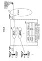
The first type is, as shown in Fig.1, a
firewall 10 (to be referred to as "terminal base
firewall" hereinafter) that is included in the own
terminal. The firewall 10 is used for protecting
the own terminal 10 against an external network (the
Internet, for example) 12.
-
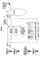
The second one is, as shown in Fig.2, a
firewall 10 (to be referred to as "CPE base
firewall" hereinafter) that is placed at an edge of
the own network 13 and is connected to the external
network 12. This firewall is used for protecting
the own network 13 against the external network 12.
-
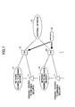
The third one is, as shown in Fig.3, a
firewall 10 (to be referred to as "NW base firewall"
hereinafter) that accommodates more than one
networks 13 or terminals 11 that are operated by
corresponding independent policies and that are
required to increase security, and the firewall is
placed at a position connecting to the external
network 12 and is used for protecting each network
13 or terminal against the external network 12.
-
As constant connection users are
increasing, necessity of security is increasing.
Under the circumstances, it is required to provide
users who do not have enough knowledge of security
with a security service for compensating for lack of
skill with low cost. In this view point, among the
above-mentioned firewalls, the NW base firewall in
which the firewall is provided in the network side
is effective.
-
That is, by using the NW base firewall,
economy by integrating accommodated users and
reduction of user activities by outsourcing can be
expected. However, since it is necessary to provide
each user with the security policy, an architecture
for constructing virtual firewalls for each user in
a physical firewall is required according to the
firewall of this method.
-
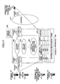
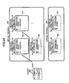
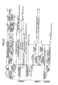
Fig.4 shows a method for constructing the
virtual firewall according to a conventional
technology. For assigning a virtual firewall to a
user's terminal, server or network, a fixed user ID
is associated with a virtual firewall ID.
-
The fixed user ID is a VLAN-ID of a
network to which the user's terminal or server
belongs, or an IP address of the user's terminal or
server. In Fig.4, an IP address [a.a.a.a] of a
sever 211 of a user #a and an IP address [b.b.b.b]
of a sever 212 of a user #b are registered in a
distribution management table 201 beforehand as
fixed user IDs in which the fixed user IDs are
associated with virtual firewall IDs 202 and 203
respectively.
-
Then, for example, in a communication
between the sever 211 and a connection partner
terminal 213 of the user #a, for a packet 221 sent
from the server 221, the distribution management
table 201 is referred to by using the source IP
address [a.a.a.a] as a search key, and the virtual
firewall ID 202 that is associated with the source
IP address [a.a.a.a] is retrieved so that the packet
221 is distributed to the virtual firewall 202. In
addition, for a packet 222 sent from the connection
partner terminal 213, the distribution management
table 201 is referred to by using the destination IP
address b.b.b.b as a search key, and the virtual
firewall ID 203 that is associated with the
destination IP address b.b.b.b is retrieved so that
the packet 222 is distributed to the virtual
firewall 203.
-
In each of the virtual firewalls 202 and
203, a filtering rule conforming to a security
policy defined by the user #a and the user #b,
respectively, is described. According to the rule,
the packet 221 and the packet 222 are passed or
discarded. Accordingly, an attacking packet from an
unauthorized access person to the server 211 can be
filtered, for example.
-
This conventional technology is mainly
applied to a data center and the like. In the data
center, since a fixed user ID is used, the user ID
can be registered in the distribution table 201
beforehand.
-
"Investigation of secure content filtering
method in a data center" (IEICE Society conference
(2002) B-6-38 2002.8.20) is a prior art document
relating to the conventional technology.
-
As another conventional technology for
setting security communications for each user, there
is a document (Japanese Laid Open Patent Application
No. 2001-298499, "Security communication method,
communication system and the apparatus). However,
the conventional technology mainly presumes IP sec
communications. Security communications for each
user defined in the document are merely for
determining the strength of an authentication
algorithm or an encryption algorithm used for
communications according to a request of a user,
which is different from a function for filtering
attacking packets due to invalid accesses.
-
In a constant connection service used by a
user, a user ID (user IP address) is assigned for
the first time when a connection between the user
terminal and a network is established. More
particularly, the user ID is assigned for the first
time when a PPP (Point to Point Protocol) session is
established. In addition, the user IP address is
generally variable.
-
Therefore, even if one tries to apply the
virtual firewall of the conventional technology to
the constant connection service, it is difficult to
apply the virtual firewall of the conventional
technology to the constant connection service since
it is impossible to register a user IP address in
the distribution management table beforehand.
-
In addition, as to the constant connection
service, since the number of accommodated users is
much larger than a case for applying the firewall to
a data center and the like, it is required to
increase the number of users to be accommodated
simultaneously by the NW based firewall apparatus.
-
Other than the viewpoint of a placement
location of a firewall, the firewall can be
classified to two types as follows from a viewpoint
of a holding method of the security policy.
-
A first firewall is one that includes the
security policy inside of the firewall. Regular
firewalls adopt this method.
-
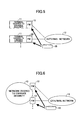
Another firewall is one, as shown in Fig.5,
6 and 7, that has the security policy outside of the
firewall 10. The security policy is distributed to
plural firewalls 10.
-
For each type of before-mentioned
firewalls (terminal base firewall, CPE base firewall,
or NW base firewall), many of the firewalls include
the security policy in the inside.
-
However, as to the firewall that uses the
method for distributing the security policy,
Japanese Laid-Open Patent Application No. 2002-544607
discloses applying such method to the
terminal base firewall. In addition, a document
(┌Distributed Firewalls┘ (Nov.1999, Special issue
on Security, ISSN 1044-63971)) discloses applying
the method to the CPE base firewall.
-
In addition, also as to the NW base
firewall, when an accommodated network or terminal
is statically connected, the same situation as the
CPE base firewall applies to the NW base firewall.
-
However, as to the NW base firewall, in a
case where the accommodated network or the terminal
is dynamically connected and disconnected, or the
accommodating NW base firewall is changed, the
method of holding the security policy in the inside
of the firewall is not useful since all security
policies relating to the networks or the terminals
that the firewall may accommodate should be held
regardless of the connection and disconnection of
the network or the terminal.
-
Therefore, in such an environment, a NW
base firewall apparatus having means for keeping an
optimum capacity of the security policies according
to connection or disconnection of the network or the
terminal becomes necessary.
-
In addition, as to the NW base firewall
having means for loading security policies in
response to connection of networks or terminals,
since plural networks or terminals are connected to
the NW base firewall, the NW base firewall may load
many security policies. In this case, processes in
the CPU of the NW base firewall for loading security
policies becomes large, so that processes of
filtering and transferring cannot be performed.
Thus, the filtering and transferring performance is
affected.
-
In addition, the apparatus that delivers
the security policy cannot distribute the security
policy when the distributing amount exceeds the
apparatus's performance.
-
Further, as to a line used for
distributing the security policy, when the
distributing amount exceeds the circuit capacity,
discard or delay may occur in distributing the
security policy.
-
Therefore, a NW base firewall apparatus
including means for reducing the security policy
amount to be delivered is necessary.
DISCLOSURE OF THE INVENTION
-
A first object of the present invention is
to provide a firewall apparatus that can provide a
service even in a communication environment in which
the user ID cannot be associated with the virtual
firewall ID beforehand.
-
In addition, a second object of the
present invention is to provide a firewall apparatus
that can increase the number of multiple users.
-
Further, a third object of the present
invention is to provide a firewall apparatus that
can hold or discard necessary security policies
according to connection or disconnection of an
accommodating network or terminal, and that can
reduce the security policy amount to be loaded.
-
The first object is achieved by a firewall
apparatus including plural virtual firewalls, each
virtual firewall including a dependent firewall
policy, the firewall apparatus including:
- a distribution management table for
managing a user name and a virtual firewall ID;
- a part configured to receive
authentication information for network connection
from a user terminal, and hold a user name included
in the authentication information;
- a part configured to report the
authentication information to the authentication
server; and
- a part configured to receive an
authentication response from the authentication
server, and hold a user ID, included in the
authentication response, to be provided to the user
terminal;
wherein the firewall apparatus registers
the user ID in the distribution management table
associating the user ID with the user name.-
-
According to the present invention, by
using the authentication information for network
connection from the user terminal, the user ID can
be dynamically associated with the virtual firewall
ID even in the communication environment in which
the user ID cannot be associated with the virtual
firewall ID beforehand. Then, the filtering rule
complying with the security policy corresponding to
the user terminal can be applied to a packet
transmitted or received by the user terminal of the
user ID.
-
The second object of the present invention
can be achieved by a firewall apparatus including:
- a distribution management table for
managing a user name, a user ID, and a filtering ID
associating them with each other;
- a filtering table, being specified by the
filtering ID, including a dependent filtering
policy;
- a part configured to receive
authentication information, issued by a user
terminal when starting network connection, so as to
hold the user name;
- a part configured to report the
authentication information to an authentication
server;
- a part configured to receive an
authentication response from the authentication
server so as to hold a user ID, included in the
authentication response, to be provided to the user
terminal,
wherein the firewall apparatus registers
the user ID in the distribution management table
associating the user ID with the user name.-
-
According to the present invention, since
the filtering ID is introduced so that the filtering
policy is identified by the filtering ID for each
user, plural independent filtering policies can be
managed in each virtual firewall so that the number
of multiple users can be increased.
-
In addition, since the search area for a
packet for each user is restricted only to a table
corresponding to a filtering ID provided to the
packet, it can be avoided that the search process
time unnecessarily increases.
-
In addition, in the present invention, the
filtering ID is divided into an individual filtering
ID and a common filtering ID so that a filtering
policy specific to each user is written in the
individual filtering table and a filtering policy
commonly used for plural users is written in the
common filtering table.
-
Accordingly, for example, in a case where
10 users use two identical filtering rules, if a
conventional technology is applied, 20 rules are
written in the filtering table. On the other hand,
according to the present invention, only two rules
need to be written in the filtering table. Thus, it
becomes possible to efficiently manage the filtering
policy.
-
The third object of the present invention
can be achieved by a firewall apparatus provided
between plural user terminals and a network and
performing filtering for the plural user terminals,
the firewall apparatus including:
- an individual filtering table holding
security policies for each user;
- a common filtering table holding a
security policy common to plural users;
- a distribution management table for
managing user terminal information, a common
filtering table ID, and an individual filtering
table ID;
- a communication part configured to
communicate with an authentication server
determining whether the user terminal is
connectable;
- a communication part configured to
communicate with an identifier management server
managing the common filtering table ID and the
individual filtering ID associated with a user;
- a communication part configured to
communicate with a security policy management server
managing correspondence between a user-specific
security policy to be written into the individual
filtering table and the user, wherein, the filtering
apparatus:
- receives a connection request with
authentication information including a user name
from the terminal when starting network connection,
holds the user name, and reports the user name to
the authentication server,
- holds user terminal information
accompanied by an authentication response received
from the authentication server,
- reports the user name to the identifier
management server and to the security policy server,
- writes the common filtering table ID, the
individual filtering table ID, and the user terminal
information received from the identifier management
server into the distribution management table
associating them with each other, and
- writes policy information received from
the security server and the individual filtering
table ID into the individual filtering table.
-
-
According to the present invention, a
necessary security policy can be loaded
simultaneously with a start of connection of the
network or the terminal.
-
In addition, an identifier indicating an
area to which the security policy is written at the
start of network connection is associated with user
terminal information provided to the network or the
terminal to start connection by authentication, so
that the identifier is determined based on the user
terminal information of the network or terminal at
the time of disconnection so as to discard the
security policy in the area indicated by the
identifier. Therefore, the security policy can be
discarded simultaneously with disconnection of the
network or the terminal.
-
In addition, according to the firewall
apparatus of the present invention, by dividing the
security policy into an individual security policy
and a common security policy, the common security
policy can be always held in the firewall apparatus
and only the individual security policy needs to be
loaded at the time of start of connection by the
network or the terminal. Therefore, the security
policy amount to be loaded can be decreased.
-
In addition, according to the firewall
apparatus of the present invention, all firewall
apparatuses can be connected to an apparatus for
distributing the security policy and an apparatus
that can check the identifier so that the firewall
apparatuses can load the security policy. Therefore,
even when the network or the terminal changes an
accommodating firewall apparatus to start network
connection or to perform disconnection, the firewall
apparatus can properly load the security policy.
BRIEF DESCRIPTION OF THE DRAWINGS
-
- Fig.1 is a block diagram showing an
example of a conventional firewall apparatus;
- Fig.2 is a block diagram showing another
example of a conventional firewall apparatus;
- Fig.3 is a block diagram showing another
example of a conventional firewall apparatus;
- Fig.4 is a diagram showing a virtual
firewall establishing method according to a
conventional technology;
- Fig.5 is a diagram showing an example of a
conventional firewall apparatus in which a security
policy is provided in its outside;
- Fig.6 is a diagram showing another example
of a conventional firewall apparatus in which a
security policy is provided in its outside;
- Fig.7 is a diagram showing another example
of a conventional firewall apparatus in which a
security policy is provided in its outside;
- Fig.8 is a diagram showing a configuration
of a firewall apparatus in an embodiment 1-1 of the
present invention;
- Fig.9 is a sequence diagram showing
operations of the firewall apparatus in the
embodiment 1-1;
- Fig.10 is a sequence diagram showing
operations of the firewall apparatus in the
embodiment 1-2;
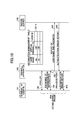
- Fig.11 is a diagram showing an example of
a distribution management table in an embodiment 1-3;
- Fig.12 is a sequence diagram showing
operations of the firewall apparatus in the
embodiment 1-3;
- Fig.13 is a diagram showing an example of
a distribution management table in the embodiment 1-4;
- Fig.14 is a sequence diagram showing
operations of the firewall apparatus in the
embodiment 1-4;
- Fig.15 is a sequence diagram showing
operations of the firewall apparatus in the
embodiment 1-5;
- Fig.16 is a diagram showing an example of
the distribution management table in the embodiment
1-5;
- Fig.17 is a block diagram showing an
outline configuration of a firewall apparatus in an
embodiment 2-1 of the present invention;
- Fig.18 is a diagram showing a
configuration of a filtering table in a virtual
firewall in the firewall apparatus in the embodiment
2-1;
- Fig.19 is a sequence diagram showing
operations of the firewall apparatus in the
embodiment 2-1;
- Fig.20 is a block diagram showing an
outline configuration of a firewall apparatus in an
embodiment 2-2 of the present invention;
- Fig.21 is a sequence diagram showing
operations of the firewall apparatus in the
embodiment 2-2;
- Fig.22 is a diagram showing an initial
state of the distribution management table in an
embodiment 2-3;
- Fig.23 is a diagram showing a state in
which an IP address is registered in the
distribution management table in an embodiment 2-3;
- Fig.24 is a diagram showing a
configuration of a filtering table in a virtual
firewall in the firewall apparatus in the embodiment
2-3;
- Fig.25 is a sequence diagram showing
operations of the firewall apparatus in the
embodiment 2-4;
- Fig.26 is a diagram showing information in
the distribution management table in the embodiment
2-5;
- Fig.27 is a sequence diagram showing
operations of the firewall apparatus in the
embodiment 2-5;
- Fig.28 is a diagram showing information in
the distribution management table in an embodiment
2-6;
- Fig.29 is a sequence diagram showing
operations of the firewall apparatus in the
embodiment 2-6;
- Fig.30 is a diagram showing information in
the distribution management table in an embodiment
2-7;
- Fig.31 is a sequence diagram showing
operations of the firewall apparatus in the
embodiment 2-7;
- Fig.32 is a diagram showing contents in a
filtering table;
- Fig.33 is a diagram showing contents in an
individual filtering table;
- Fig.34 is a block diagram showing an
outline configuration of a firewall apparatus and a
network model in which the firewall apparatus is
used according to embodiment 3-1 of the present
invention;
- Fig.35 is a diagram showing detail of
authentication information in an authentication
server shown in Fig.34;
- Fig.36 is a diagram showing detail of a
pool table held in a user terminal information part
in the authentication server shown in Fig.34;
- Fig.37 is a diagram showing detail of an
identifier management table in the identifier
management server shown in Fig.34;
- Fig.38 is a diagram showing detail of a
security policy table in the security policy server
shown in Fig.34;
- Fig.39 is a diagram showing detail of the
distribution management table, in an initial state,
in the firewall apparatus shown in Fig.34;
- Fig.40 is a diagram showing an example of
a sequence of operations of the network model shown
in Fig.34;
- Fig.41 is a diagram showing an example of
a sequence of operations of the network model shown
in Fig.34;
- Fig.42 is a block diagram showing an
outline configuration of a firewall apparatus and a
network model in which the firewall apparatus is
used according to an embodiment 3-2;
- Fig.43 is a diagram showing an example of
a sequence of operations of the network model shown
in Fig.42;
- Fig.44 is a block diagram showing an
outline configuration of a firewall apparatus and a
network model in which the firewall apparatus is
used according to an embodiment 3-3;
- Fig.45 is a diagram showing an example of
a sequence of operations of the network model shown
in Fig.44;
- Fig.46 is a block diagram showing an
outline configuration of a firewall apparatus and a
network model in which the firewall apparatus is
used according to an embodiment 3-4;
- Fig.47 is a diagram showing an example of
a sequence of operations of the network model shown
in Fig.46;
- Fig.48 is a block diagram showing an
outline configuration of a firewall apparatus and a
network model in which the firewall apparatus is
used according to an embodiment 3-5;
- Fig.49 is a diagram showing an example of
a sequence of operations of the network model shown
in Fig.48;
- Fig.50 is a block diagram showing an
outline configuration of a firewall apparatus and a
network model in which the firewall apparatus is
used according to an embodiment 3-6;
- Fig.51 is a diagram showing details of
authentication information in an authentication
server 1 shown in Fig.50;
- Fig.52 is a diagram showing details of a
pool table held in a user terminal information part
in the authentication server 1 shown in Fig.50;
- Fig.53 is a diagram showing details of
authentication information in an authentication
server 2 shown in Fig.50;
- Fig.54 is a diagram showing details of a
pool table held in a user terminal information part
in the authentication server 2 shown in Fig.50;
- Fig.55 is a diagram showing a user name
sent to the firewall apparatus via the user terminal
(2002-1) by the user (2015-1);
- Fig.56 is a diagram showing a user name
sent to the firewall apparatus via the user terminal
(2002-2) by the user (2015-2);
- Fig.57 is a diagram showing details of
a identifier management table 2012 in the identifier
management server shown in Fig.50;
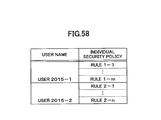
- Fig.58 is a diagram showing details of a
security policy table in the security policy server
shown in Fig.50;
- Fig.59 is a diagram showing one example of
a sequence of operations of the network model shown
in Fig.50;
- Fig.60 is a diagram showing another
example of a sequence of operations of the network
model shown in Fig.50;
- Fig.61 is a diagram showing a
configuration example of a computer system.
-
PREFERRED EMBODIMENTS FOR CARRYING OUT THE INVENTION
-
In the following, embodiments of the
present invention are described with reference to
figures.
(Embodiment 1-1 - embodiment 1-5)
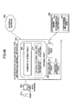
[Embodiment 1-1]
-
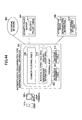
First, an embodiment 1-1 of the present
invention is described with reference to Figs.8 and
9. In this embodiment, it is assumed that the
method of connecting to the network from the user is
PPP, and the authentication communication method is
RADIUS.
-
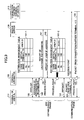
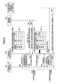
The firewall apparatus 100 includes a
virtual firewall for each user. For example, the
firewall apparatus 100 includes a virtual firewall
102 to which a security policy of the user #a is
applied for protecting a terminal 111 of the user #a,
and a virtual firewall 103 to which a security
policy of the user #b is applied for protecting a
terminal 112 of the user #b.
-
In a distribution management table 101,
user names and virtual firewall IDs that can be set
beforehand are registered. That is, the
distribution management table 101 registers
associations between a user name #a and a virtual
firewall ID 102, and a user name #b and a virtual
firewall ID 103. However, since each user IP
address that is a user ID for each user terminal has
not been determined, it cannot be registered at this
time (in a state of the distribution management
table 101-1).
-
In this example, it is assumed that the
terminal 111 of the user #a connects to the Internet
110, and, after that, the terminal 111 performs IP
communications with a connection partner terminal
113. First, as a network connection request from
the user terminal 111, information of LPC (Link
Control Protocol) is exchanged between the user
terminal 111 and the firewall apparatus 100 (139).
After that, by exchanging authentication information
(140), the firewall apparatus 100 extracts the user
name #a sent from the user terminal 111 and holds
the user name #a (process point 150).
-
Then, the authentication information (user
name and password) are sent to the RADIUS server 130
(141). The authentication is performed by the
RADIUS server 130, and the firewall apparatus 100
receives the response 142 so that the firewall
apparatus 100 holds a user IP address, included in
the response 142, to be supplied to the user
terminal. Assume that the user IP address is
[a.a.a.a]. Then, by using the user name #a as a
search key, the firewall apparatus registers the
user IP address [a.a.a.a] in a line including #a as
the user name (process point 151, a state of the
distribution management table 101-2).
-
At the same time, while information of NCP
(Network Control Protocol) is exchanged between the
user terminal 111 and the firewall apparatus 100
(143), the firewall apparatus 100 sends the user IP
address [a.a.a.a] to the user terminal 111 so that
the user terminal 111 recognizes that the own IP
address is [a.a.a.a].
-
After completing NCP, a PPP connection is
established between the user terminal and the
network. After that, when the firewall apparatus
100 receives a packet 121 that is sent from the user
terminal 111 to the connection partner terminal 113,
the firewall apparatus 100 refers to the
distribution management table 101 by using [a.a.a.a],
as a search key, included in the packet as the
source IP address so as to extract the virtual
firewall ID=102 and distribute the packet 121 to the
virtual firewall 102 (process point 152).
Accordingly, a pass or discard process is applied to
the packet 121 according to a filtering rule
according to the security policy determined by the
user #a.
-
In addition, when the firewall apparatus 100
receives a packet 122 that is sent from the
connection partner terminal 113 to the user terminal
111, the firewall apparatus 100 refers to the
distribution management table 101 by using [a.a.a.a],
as a search key, included in the packet as the
destination IP address so as to extract the virtual
firewall ID=102 included in the line of [a.a.a.a],
and distributes the packet 122 to the virtual
firewall 102 (process point 153). Accordingly, the
pass or discard process is applied to the packet 122
according to a filtering rule according to the
security policy determined by the user #a.
-
A similar procedure is applied to a case
where the terminal 112 of the user #b connects to
the Internet 110 and the terminal 112 performs IP
communications with a connection partner terminal
113. That is, the packet sent and received by the
terminal 112 is distributed to the virtual firewall
103, so that the pass or discard process is applied
to the packet according to a filtering rule
according to a security policy determined by the
user #b.
[Embodiment 1-2]
-
The embodiment 1-2 of the present
invention is described with reference to Fig.10.
This embodiment shows a case where the combination
of the user name and the password sent by the report
141 of the user name and the password in the
embodiment 1-1 is not the same as the combination of
the user name and the password registered in the
RADIUS server 130 for the reason that the user name
or the password sent from the user #a is not correct.
-
Since the process of the report 141 of the
user name and the password from the LCP 139 is the
same as that of the embodiment 1-1, the process is
not described in this embodiment.
-
When an authentication error report 642 is
sent from the RADIUS server 130 due to the above-mentioned
reason, the firewall apparatus 100 sends
an authentication error report 643 to the user
terminal 111, and terminates the PPP establishment
process. In this case, the firewall apparatus 100
does not perform any process for the distribution
management table 101.
[Embodiment 1-3]
-
The embodiment 1-3 of the present
invention is described with reference to Figs.8, 11
and 12. This embodiment shows a case where a
terminal 114 of a firewall-service-unregistered user
#c connects to the Internet 110, and, after that,
the terminal 114 performs IP communications with a
connection partner terminal 113. As to the
firewall-service-unregistered user #c, the user name
and the virtual firewall are not registered in the
distribution management table 101-3. But the user
#c receives a communication service to the Internet
110 via the terminal 114, and the user name and the
password are registered in the RADIUS server 130.
-
In Fig.12, operations from the start to
the report 142 of the use IP address are the same as
those of the embodiment 1-1.
-
When the firewall apparatus 100 receives
the report 142 of the user IP address, the firewall
apparatus 100 holds a user IP address [c.c.c.c],
included in the report 142 of the user IP address,
to be provided to the user terminal. Then, the
firewall apparatus 100 searches the distribution
management table 101-3 for the user name #c. But,
since the user name #c does not exist, the firewall
apparatus 100 does not register the user IP address
[c.c.c.c] in the distribution management table 101-3.
-
In addition, at the same time, while the
firewall apparatus 100 exchanges information of NCP
with the user terminal 114 in (143), the firewall
apparatus 100 sends the user IP address [c.c.c.c] to
the user terminal 114, and the user terminal 114
recognizes that the own user IP address is [c.c.c.c].
-
After completing NCP, a PPP connection is
established between the user terminal and the
network. After that, the firewall apparatus 100
receives a packet 121 that is sent from the user
terminal 114 to the connection partner terminal 113,
and the firewall apparatus 100 refers to the
distribution management table 101 by using [c.c.c.c],
as a search key, included in the packet 121 as a
source IP address, so that it is determined that the
source IP address is not registered.
-
When the source IP address is not
registered, since a virtual firewall to which the
packet is to be distributed is written as a virtual
firewall 104 in a last line in the distribution
management table 101-3 as shown in Fig.11, the
packet 121 is distributed to the virtual firewall
104 for the unregistered user (process point 152).
-
In the same way, also as for a packet 122
sent from the communication partner terminal 113,
when the firewall apparatus 100 refers to the
distribution management table 101 by using the
destination user IP address [c.c.c.c] as a search
key, it is determined that the destination IP
address is not registered, so that the packet 122 is
distributed to the virtual firewall 104 for the
unregistered user (process point 153).
-
The virtual firewall 104 for the
unregistered user does not include a filtering rule
to unconditionally pass all packets, or includes a
filtering rule common for all unregistered users.
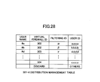
[Embodiment 1-4]
-
The embodiment 1-4 of the present
invention is described with reference to Figs.8, 13
and 14. This embodiment shows a case where the
terminal 114 of the firewall-service-unregistered
user #c connects to the Internet 110, and, after
that, the terminal 114 performs IP communications
with the connection partner terminal 113 in the same
way as the embodiment 1-3. As to the firewall-service-unregistered
user #c, the user name and the
virtual firewall are not registered in the
distribution management table 101-4. But, the user
#c receives a communication service to the Internet
110 via the terminal 114, and the user name and the
password are registered in the RADIUS server 130.
-
In Fig.14, operations from the start to
the notification 142 of the use IP address are the
same as those of the embodiment 1-1.
-
When the firewall apparatus 100 receives
the report 142 of the user IP address, the firewall
apparatus 100 holds the user IP address [c.c.c.c],
included in the report 142 of the user IP address,
to be provided to the user terminal. Then, the
firewall apparatus 100 searches the distribution
management table 101-4 for the user name #c. But,
the user name #c does not exist. In this case, the
firewall apparatus 100 registers the user IP address
[c.c.c.c] and ID=104 of the virtual firewall 104 for
unregistered users in the distribution management
table 101-4.
-
In addition, at the same time, while the
firewall apparatus 100 exchanges information of NCP
with the user terminal 114 in (143), the firewall
apparatus 100 sends the user IP address [c.c.c.c] to
the user terminal 114, and the user terminal 114
recognizes that the own user IP address is [c.c.c.c].
-
After completing NCP, a PPP connection is
established between the user terminal and the
network. After that, the firewall apparatus 100
receives a packet 121 that is sent from the user
terminal 114 to the connection partner terminal 113,
and the firewall apparatus 100 refers to the
distribution management table 101 by using [c.c.c.c],
as a search key, included in the packet 121 as a
source IP address, so that the firewall apparatus
100 retrieves the virtual firewall ID = 104 that is
associated with the source IP address so as to
distribute the packet 121 to the virtual firewall
104 (process point 152).
-
In the same way, also as for a packet 122
sent from the communication partner terminal 113,
the firewall apparatus 100 refers to the
distribution management table 101-4 by using
[c.c.c.c] as a search key, included in the packet
121 as a destination IP address, so that the
firewall apparatus 100 retrieves the virtual
firewall ID = 104 that is associated with the
destination IP address so as to distribute the
packet 121 to the virtual firewall 104 (process
point 153).
-
In the same way as the embodiment 1-3, the
virtual firewall 104 for the unregistered users does
not include a filtering rule to unconditionally pass
all packets, or includes a filtering rule common for
all unregistered users.
-
In addition, when the source IP address is
not registered, the packet is discarded as shown in
the last line of the distribution management table
101-4 in Fig.13. Accordingly, when a malicious user
sends, in an IP Spoofing attack and the like, a
large amount of packets having an IP address that is
not assigned to any user, the firewall apparatus 100
can discard the packets.
[Embodiment 1-5]
-
The embodiment 1-5 of the present
invention is described with reference to Figs.8, 15
and 16. This embodiment shows a case where a
terminal 115 of a firewall-service-unregistered user
#d connects to the Internet 110, and, after that,
the terminal 115 performs IP communications with a
connection partner terminal 113. The user #d is a
user who should be registered in the firewall
service. But, in this case, the user name #d is not
correctly registered in the distribution management
table 101-5 for the reason that the manager of the
firewall apparatus 100 forgot about registering the
user name #d in the distribution management table
101-5 or erroneously registered the user name.
However, the user name #d and the password are
correctly registered in the RADIUS server 130.
-
In Fig.15, operations from the start to
the report 142 of the user IP address are the same
as those of the embodiment 1-1, and the description
is not presented here.
-
When the firewall apparatus 100 receives
the report 142 of the user IP address, the firewall
apparatus 100 holds the user IP address [d.d.d.d],
included in the report 142 of the user IP address,
to be provided to the user terminal. Then, the
firewall apparatus 100 searches the distribution
management table 101-5 for the user name #d. The
user name #d does not exist. When the user name
does not exist, the firewall apparatus sends an
authentication error report 943 to the user terminal
115, and ends the PPP establishment process.
(Effects of the embodiments 1-1 ~ 1-5)
-
The firewall apparatus in the embodiment
1-1 includes means for dynamically registering the
user IP address in the distribution management table
for a case where a user IP address is assigned for
the first time when the connection between the user
terminal and the network is established and the
value of the user IP address is variable like the
constant connection service. In addition, the
firewall apparatus supporting dynamic user
identifier of the present invention includes virtual
firewalls for each user.
-
Accordingly, in a communication
environment in which associating the user IP address
with the virtual firewall ID cannot be performed
beforehand, authentication information from the user
terminal for network connection can be used so that
the user IP address is dynamically associated with
the virtual firewall ID so as to apply a filtering
rule complying with security policy that the user
defines to packets that the user terminal transmits
or receives. In addition, savings due to
integration of accommodating users and reduction of
user workload due to outsourcing become possible.
-
As to the firewall apparatus of the
embodiment 1-2, when the user name or the password
sent from the user includes an error and an
authentication error report from the RADIUS server
is sent, the authentication error report is
transmitted to the user terminal without any
processing on the distribution management table.
Accordingly, distribution management table search
and registration processes are prevented when
network connection is refused, so that a surplus of
processing ability can be used for other processes.
-
The firewall apparatuses of the embodiment
1-3 and the embodiment 1-4 can accommodate a user
terminal of a user who does not use the firewall
service, so that inconvenience for changing physical
connections can be eliminated which inconvenience
occurs each time when each user who does not use the
firewall service uses a service.
-
In addition, as to the means in the
embodiment 1-3, the unregistered user is not
registered in the distribution management table, so
that transmit/receive packet of the unregistered
user is automatically distributed to the virtual
firewall for unregistered users. Thus, the number
of entries registered in the distribution management
table can be limited to registered users who are
currently establishing a network connection, so that
search time can be decreased.
-
On the other hand, as to the means of the
embodiment 1-4, the unregistered user is registered
in the distribution management table, and the
transmission/receive packet of the unregistered user
is distributed to a virtual firewall for
unregistered users. In addition, when a user is not
registered in the distribution management table, the
packet of the user is discarded. Thus, when a
malicious user transmits large amount of packets
having an IP address that is not assigned to any
user for the purpose of IP Spoofing attack and the
like, the firewall apparatus can discard these
packets.
-
As mentioned above, each means of the
embodiment 1-3 and the embodiment 1-4 can be used
differently according to usage.
-
As to the firewall apparatus of the
embodiment 1-5, when a manager of the firewall
apparatus forgets about registering the user name in
the distribution management table or erroneously
registers the user name, communication that should
not be established can be forced to terminate from
the viewpoint of security.
(Embodiment 2-1 ~ embodiment 2-7)
-
Next, the embodiment 2-1 ~ the embodiment
2-7 are described.
-
According to the operation shown in the
embodiment 1-1 and the like, in a communication
environment in which associating the user IP address
with the virtual firewall ID cannot be performed
beforehand, authentication information for network
connection from the user terminal can be used so
that the user IP address is dynamically associated
with the virtual firewall ID so as to apply a
filtering rule complying with security policy that
the user defines to packets that the user terminal
transmits or receives.
-
However, in the case of the constant
connection service, the number of accommodated users
is much larger than the number of users in a data
center.
-
In the case of the data center, an
estimated number of accommodated users is several
hundreds to several thousands. On the other hand,
in the case of the constant connection service, the
number of accommodated users is several tens of
thousands to several hundreds of thousands.
-
Currently, many of implemented reliable
virtual firewall apparatuses introduced in a service
have been developed for the data center, so that the
number of users that can be actually accommodated is
several hundreds to several thousands as mentioned
above.
-
Although the number of the accommodated
users is different for developing the virtual
firewall apparatus for the constant connection
service, diverting development and adding
development based on the virtual firewall apparatus
for the data center is very effective from the
viewpoint of efficiency of development and
utilization of existing technology.
-
Therefore, the problem of providing the
virtual firewall apparatus for the constant
connection service is increasing the multiple number
of users.
-
In addition, the number of multiple users
is large in the constant connection service, the
number of sum of filtering rules increases in
proportion to the number of multiple users for
keeping serviceability for providing independent
security policy for each user.
-
However, in actuality, there are many
filtering rules commonly used for users so that the
rules overlap in view of the firewall apparatus as a
whole, which is inefficient. As a result, it leads
to an increase in the amount of filtering tables.
-
As mentioned above, for developing the
virtual firewall apparatus for the constant
connection service, increase of the number of
multiple users and efficiency of the filtering
tables are problems to be solved.
-
In embodiments 2-1 ~ 2-7, a firewall
apparatus that increases the multiple number of
users and that increases efficiency of the filtering
tables is described.
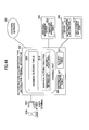
[Embodiment 2-1]
-
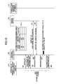
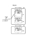
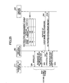
Fig.17 is a block diagram showing an
outline configuration of a firewall apparatus of the
embodiment 2-1 of the present invention. Fig.18 is
a diagram showing a configuration of a filtering
table in the virtual firewall in the present
embodiment.
-
In this embodiment, it is assumed that the
method for network connection from the user is PPP
(Point to point Protocol), and communication for
authentication is RADIUS.
-
The firewall apparatus 300 includes plural
virtual firewalls (302, 303, ..., 304).
-
Further, as shown in Fig.18, each firewall
(302, 303) includes plural filtering tables (561,
562, 563) each being identified by a corresponding
filtering ID, and each filtering table (561, 562,
563) includes one or more filtering policies
independent of each user.
-
In the present embodiment, security
policies defined by the user #a and the user #b are
stored in the virtual firewall 302, and a security
policy defined by the user #d is stored in the
virtual firewall 303.
-
Further, in the virtual firewall 302, the
security policy of the user #a is written in the
filtering table 561 whose filtering ID is α, the
security policy of the user #b is written in the
filtering table 562 whose filtering ID is β. In
addition, the security policy of the user #d is
written in the filtering table 563 whose filtering
ID is γ in the virtual firewall 303.
-
The reason why the user #a and the user #b
are accommodated in the same virtual firewall 302 is
that, for example, common filtering policies for the
user #a and the user #b are the same, or the virtual
firewall is established for each Internet provider
and the user #a and the user #b belong to the same
Internet provider.
-
In the distribution management table 301,
user names, virtual firewall IDs and filtering IDs
that can be set beforehand are registered.
-
That is, in the distribution management
table 301, correspondence among the user #a, the
virtual firewall ID (302) and the filtering ID (α),
correspondence among the user #b, the virtual
firewall ID (302) and the filtering ID (β), and
correspondence between the virtual firewall ID (303)
and the filtering ID (γ) are registered.
-
However, the user IP address that is a
user ID of each user terminal is not decided so that
it cannot be registered at this time (state of
distribution management table 301-1 in Fig.19).
-
Unless the user IP address is registered
in the distribution management table 301, it cannot
be performed to distribute packets from each user to
a corresponding virtual firewall and to assign a
filtering ID.
-
In the present embodiment, the terminal
311 of the user #a connects to the Internet 310, and
after that, the terminal 311 performs IP
communications with a connection partner terminal
313.
-
In the following, by using Fig.19, the
operation of the firewall apparatus of the present
embodiment is described. Fig.19 is a sequence
diagram indicating operations of the firewall
apparatus of the present embodiment.
-
First, as a network connection request
from the user terminal 311, information of LCP is
exchanged between the user terminal 311 and the
firewall apparatus 300 (839 in Fig.19).
-
Based on the exchange of authentication
information that is performed after that (840 in
Fig.19), the firewall apparatus 300 extracts the
user name #a sent from the user terminal 311 so as
to hold the user name #a (process point 850 in
Fig.19).
-
Then, the authentication information
(user name and password) is reported to the RADIUS
server 330 (841 in Fig.19).
-
The RADIUS server 330 performs
authentication. When the firewall apparatus
receives the response (842 in Fig.19), the firewall
apparatus 300 holds a user IP address to be assigned
to the user terminal included in the response. It
is assumed that the user IP address is [a. a. a. a].
-
Then, by using the user name #a as a
search key, the firewall apparatus 300 registers the
user IP address [a. a. a. a] into a line that
includes #a as a user name in the distribution
management table (process point 851 in Fig.19 state
of distribution management table 301-2 in Fig.19).
-
In addition, at the same time, the
firewall apparatus 300 sends the user IP address [a.
a. a. a] to the user terminal 311 so that the user
terminal ascertains that the own user IP address is
[a. a. a. a] while exchanging information of NCP
(Network Control Protocol) between the user
terminal 311 and the firewall apparatus 300.
-
After exchanging NCP, a PPP connection is
established between the user terminal 311 and the
Internet 320.
-
After that, when the firewall apparatus
300 receives a packet 321 sent from the user
terminal 311 to the connection partner terminal 313,
the firewall apparatus 300 searches the distribution
management table (301-2 in Fig.19) by using, as a
search key, [a. a. a. a] included in the packet as
the source IP address so as to extract a virtual
firewall ID (ID=302) and a filtering ID (ID=α),
distribute the packet 321 to the virtual firewall
302 and assign the filtering ID α to the packet 321
(process point 852 in Fig.19).
-
As shown in Fig.18, a "pass" or "discard"
process is applied to the packet 322 to which the
filtering ID has been assigned according to a
filtering rule complying with the security policy of
the user #a included in the filtering table 561
having filtering ID α.
-
In addition, when the firewall apparatus 300
receives a packet 323 sent from the communication
partner terminal 313 to the user terminal 311, the
firewall apparatus 300 searches the distribution
management table (301-2 in Fig.19) by using, as a
search key, [a. a. a. a] included in the packet as
the destination IP address so as to extract the
virtual firewall ID (ID=302) and the filtering ID
(ID=α) included in a line of [a. a. a. a] and
assign filtering ID α to the packet 323 (process
point 853 in Fig.19).
-
In the virtual firewall 302 to which the
packet 324, to which the filtering ID is assigned,
is distributed, the passing or discarding process is
applied to the packet 324 according to a filtering
rule complying with a security policy of the user #a
written in the filtering table 561 corresponding to
the filtering ID α.
-
Also in a case where the terminal 312 of
the user #b connects to the Internet 310 via a
network, and after that, performs IP communications
with the connection partner terminal 313, a similar
procedure is applied. That is, a packet
sent/received by the terminal 312 is distributed to
the virtual firewall 302; after that, the passing or
discarding process is applied to the packet
according to a filtering rule complying with a
security policy of the user #b in the filtering
table 562.
-
As described above, in this embodiment, by
introducing the filtering ID (α,β,γ), plural
independent filtering policies can be managed by
each virtual firewall (302, 303, 304) so that the
number of multiple users can be increased.
-
In addition, as to a search region for a
packet for each user, only a table having the same
filtering ID assigned to the packet is searched, so
it can be avoided that search process time becomes
unnecessarily long.
[Embodiment 2-2]
-
The firewall apparatus of the embodiment
2-2 of the present invention is different from the
firewall apparatus in the before-mentioned
embodiment 2-1 in that the firewall apparatus of the
embodiment 2-2 does not include the virtual firewall.
-
In the following, as for the firewall
apparatus of this embodiment, features different
from the firewall apparatus of the embodiment 2-1
are mainly described.
-
Also in this embodiment, it is assumed
that the network connection method from the user is
PPP and authentication communication is RADIUS.
-
Fig.20 is a block diagram showing an
outline configuration of the firewall apparatus of
the embodiment 2-2 of the present invention.
-
As shown in Fig.20, the firewall apparatus
300 of this embodiment includes plural filtering
tables (561, 562) each being identified by a
corresponding filtering ID, and each filtering table
includes an independent filtering policy for each
user.
-
In this embodiment, a security policy of
the user #a is written in the filtering table 561 to
which α is assigned as the filtering ID, and a
security policy of the user #b is written in the
filtering table 562 to which β is assigned as the
filtering ID.
-
In the distribution management table 301,
user names and filtering IDs that can be set
beforehand are registered.
-
That is, in the distribution management
table 301, correspondence between the user name #a,
and the filtering ID (α), and correspondence
between the user name #b and the filtering ID (β)
are registered.
-
However, the user IP address that becomes
a user ID of each user terminal is not decided so
that it cannot be registered at this time (state of
distribution management table 301-1 in Fig.21).
-
Unless the user IP address is registered
in the distribution management table 301, it cannot
be performed to assign a filtering ID to a packet
from each user.
-
In the present embodiment, it is assumed
that the terminal 311 of the user #a connects to the
Internet 310 via a network, and after that, the
terminal 311 performs IP communications with a
connection partner terminal 313.
-
In the following, by using Fig.21, the
operations of the firewall apparatus of the present
embodiment are described. Fig.21 is a sequence
diagram indicating operations of the firewall
apparatus of the present embodiment.
-
Operations from exchange (839 in Fig.21)
of information of LCP between the user terminal 311
and the firewall apparatus 300 to exchange (843 in
Fig.21) of information of NCP between the user
terminal 311 and the firewall apparatus 300 are the
same as those in the embodiment 2-1. Thus, the
description for the operations are not provided.
-
After NCP ends, PPP connection is
established between the user terminal 311 and the
Internet 320. After that, when the firewall
apparatus 300 receives a packet 321 sent from the
user terminal 311 to the connection partner terminal
313, the firewall apparatus 300 searches the
distribution management table (301-2 in Fig.21) by
using, as a search key, [a. a. a. a] included in the
packet as a source IP address so as to extract a
filtering ID (ID=α), and assign the filtering ID α
to the packet 321 (process point 852 in Fig.21).
-
A passing or discarding process is applied
to the packet 323 to which the filtering ID has been
assigned according to a filtering rule complying
with the security policy of the user #a included in
the filtering table 561 having filtering ID α.
-
In addition, when the firewall apparatus 300
receives the packet 323 sent from the communication
partner terminal 313 to the user terminal 311, the
firewall apparatus 300 searches the distribution
management table (301-2 in Fig.21) by using, as a
search key, [a. a. a. a] included in the packet as
the destination IP address so as to extract the
filtering ID (ID=α) included in a line of [a. a. a.
a] and assign filtering ID α to the packet 323
(process point 853 in Fig.21).
-
The passing or discarding process is
applied to the packet 324 to which the filtering ID
has been assigned according to a filtering rule
complying with a security policy of the user #a
written in the filtering table 561 corresponding to
the filtering ID α.
-
Also in a case where the terminal 312 of
the user #b connects to the Internet 310 via a
network, and after that, performs IP communications
with the connection partner terminal 313, a similar
procedure is applied. That is, the passing or
discarding process is applied to the packet
sent/received by the terminal 312, according to a
filtering rule complying with a security policy of
the user #b in the filtering table 562.
[Embodiment 2-3]
-
The firewall apparatus of the embodiment
2-3 of the present invention is different from the
firewall apparatus in the above-mentioned embodiment
2-1 in that the filtering ID is classified into two
types: individual filtering ID and common filtering
ID.
-
In the following, as for the firewall
apparatus of this embodiment, features different
from the firewall apparatus of the embodiment 2-1
are mainly described.
-
An outline configuration of the firewall
apparatus of this embodiment 2-3 is the same as that
shown in Fig.17. Also in this embodiment, it is
assumed that the network connection method from the
user is PPP and authentication communication is
RADIUS.
-
In the firewall apparatus of this
embodiment, the filtering ID of the embodiment 2-1
is divided to an individual filtering ID and a
common filtering ID, so that filtering policies
specific for each user are included in corresponding
individual filtering tables, and a filtering policy
that can be commonly used for plural users is
included in the common filtering table.
-
Therefore, in this embodiment, each of the
distribution management table 301 in Fig.17 and the
distribution management table (301-1) in Fig.19 is
replaced by a distribution management table 601
shown in Fig.22, and the distribution management
table (301-2) shown in Fig.19 is replaced by a
distribution management table shown in Fig.23.
-
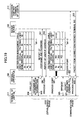
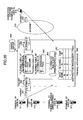
Fig.24 is a diagram showing a
configuration of a filtering table in the virtual
firewall in the firewall apparatus of this
embodiment.
-
The firewall apparatus 300 of this
embodiment includes plural virtual firewalls (302,
303, ..., 304).
-
In addition, as shown in Fig.24, each
virtual firewall (302, 303) includes plural
filtering tables (561, 562, 563) identified by
corresponding individual filtering IDs and plural
filtering tables (571, 572) identified by the common
filtering ID.
-
Filtering policies specific for each user
are written in corresponding individual filtering
tables (561, 562, 563), and filtering policies
commonly used plural users are written in the common
filtering tables (571, 572).
-
Being associated with that, as shown in
Fig.22, the distribution management table 601
manages user name, virtual firewall ID, individual
filtering ID and common filtering ID.
-
In this embodiment, security policies
defined by the user #a and the user #b are stored in
the virtual firewall 302, security policies defined
by the user #d are stored in the virtual firewall
303, and further, individual filtering policies of
the user #a are written in the individual filtering
table 561 to which α is assigned as the filtering
ID in the virtual firewall 302, individual filtering
policies of the user #b are written in the
individual filtering table 562 to which β is
assigned as the filtering ID in the virtual firewall
302, individual filtering policies of the user #d
are written in the individual filtering table 563 to
which γ is assigned as the filtering ID in the
virtual firewall 303.
-
Filtering policies written in a common
filtering table 571 to which "I" is assigned as the
filtering ID are also applied to the user #a and the
user #b.
-
In the same way, filtering policies
written in a common filtering table 572 to which
"II" is assigned as the filtering ID are also
applied to the user #d.
-
In the distribution management table 601,
user names, virtual firewall IDs, individual
filtering IDs and common filtering IDs that can be
set beforehand are registered.
-
That is, the distribution management table
601 registers correspondence among the user name #a,
the virtual firewall ID (302), the individual
filtering ID (α), and the common firewall ID (I);
correspondence between the individual filtering ID
(β) and the common filtering ID (I); and
correspondence among the user name #b, the virtual
firewall ID (303), the individual filtering ID (γ),
and the common firewall ID (II).
-
However, the user IP address that is a
user ID of each user terminal is not decided so that
it cannot be registered at this time (state of
distribution management table 601-1 in Fig.22).
-
Unless the user IP address is registered
in the distribution management table 601, it cannot
be performed to distribute packets from each user to
a corresponding virtual firewall and to assign an
individual filtering ID and a common filtering ID.
-
In the present embodiment, it is assumed
that the terminal 311 of the user #a is connected to
the Internet 310, and after that, the terminal 311
performs IP communications with a connection partner
terminal 313.
-
In the following, by using Fig.19, the
operation of the firewall apparatus of the present
embodiment is described.
-
Operations from exchange of information of
LCP between the user terminal 311 and the firewall
apparatus 300 to exchange of information of NCP
between the user terminal 311 and the firewall
apparatus 300 are the same as those in the
embodiment 2-1. Thus, the description for the
operations are not provided.
-
After NCP ends, PPP connection is
established between the user terminal 311 and the
Internet 320. After that, as shown in Fig.17, when
the firewall apparatus 300 receives a packet 321
sent from the user terminal 311 to the connection
partner terminal 313, the firewall apparatus 300
searches a distribution management table 1101 by
using, as a search key, [a. a. a. a] included in the
packet as the source IP address so as to extract the
virtual firewall ID (ID=302), the individual
filtering ID (ID=α) and the common filtering ID
(ID=I), distribute the packet 321 to the virtual
firewall 302 and assign the individual filtering ID
α and the common filtering ID I to the packet 321
(process point 852 in Fig.19).
-
As shown in Fig.24, as for the packet 322
to which the individual filtering ID and the common
filtering ID are assigned, a passing or discarding
process is applied to the packet 322 according to a
filtering rule complying with the security policy of
the user #a written in the individual filtering
table 561 having α as the filtering ID.
-
If any rule to be applied does not exist
in the filtering policy written in the individual
filtering table 561, the passing or discarding
process is performed for the packet according to the
filtering policy written in the common filtering
table 571 to which I is assigned as the common
filtering ID.
-
In addition, when the firewall apparatus
300 receives the packet 323 sent from the
communication partner terminal 313 to the user
terminal 311, the firewall apparatus 300 searches
the distribution management table 1101 by using, as
a search key, [a. a. a. a] included in the packet as
the destination IP address so as to extract the
virtual firewall ID (ID=302), the individual
filtering ID (ID=α) and the common filtering ID
(ID=I) included in a line of [a. a. a. a], and
distributes the packet 323 to the virtual firewall
302 and assigns the filtering ID α and the common
filtering ID I to the packet 323 (process point 853
in Fig.19).
-
As for the packet 324 to which the
individual filtering ID and the common filtering ID
are assigned, the passing or discarding process is
applied to the packet 324 according to a filtering
rule complying with the security policy of the user
#a written in the individual filtering table 561
having α as the filtering ID.
-
If any rule to be applied does not exist
in the filtering policy written in the individual
filtering table 561, the passing or discarding
process is performed for the packet according to the
filtering policy written in the common filtering
table 571 to which I is assigned as the common
filtering ID.
-
As described above, according to the
present embodiment, when 10 users similarly use two
filtering rules, for example, 20 rules are written
in the filtering table by applying a conventional
technology. In contrast, according to the present
embodiment, only two rules need to be written in the
filtering table.
-
That is, by introducing the common
filtering ID and the common filtering table, the
filtering policies can be efficiently managed.
-
Also in the embodiment 2-2 in which the
virtual firewall is not used, the individual
filtering table and the common filtering table in
this embodiment can be introduced. In such a case,
in the embodiment 2-2, the distribution management
table is provided with the individual filtering ID
and the common filtering ID similar to those of this
embodiment instead of the filtering ID, and is
provided with the individual filtering table and the
common filtering table similar to those of this
embodiment instead of the filtering table.
[Embodiment 2-4]
-
This embodiment of the firewall apparatus
is an embodiment in which, in the firewall apparatus
of the embodiments 2-1 or 2-2, the combination of
the user name and the password sent by the report of
the user name and the password is not the same as
the combination of the user name and the password
registered in the RADIUS server 330 for the reason
that the user name or the password sent from the
user #a is not correct, for example.
-
Operations of the firewall apparatus of
the embodiment 2-4 are described with reference to
Fig.25. Fig.25 is a sequence chart showing the
operations of the firewall apparatus of the
embodiment 2-4.
-
Since the processes from the LCP (339 in
Fig.25) to the report (341 in Fig.25) of the user
name and the password are the same as those of the
embodiment 2-1, the processes are not described in
this embodiment.
-
When an authentication error report is
sent from the RADIUS server 330 due to the above-mentioned
reason (1242 in Fig.25), the firewall
apparatus 300 sends an authentication error report
to the user terminal 311 (1243 in Fig.25), and
terminates the PPP establishment process. In this
case, the firewall apparatus 300 does not perform
any process on the distribution management table 301.
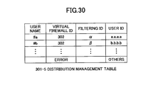
[Embodiment 2-5]
-
This embodiment of the firewall apparatus
is an embodiment in which, in the firewall apparatus
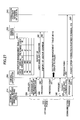
of the embodiment 2-1, a terminal 314 of a firewall-service-unregistered
user #c connects to the
Internet 310, and, after that, the terminal 314
performs IP communications with a connection partner
terminal 313.
-
An outline configuration of the firewall
apparatus of this embodiment 2-5 is the same as that
of Fig.17, and Fig.26 is a diagram showing
information of the distribution management table of
this embodiment.
-
As to the firewall-service-unregistered
user #c, the user name and the virtual firewall are
not registered in the distribution management table
301-3. But, the user #c receives a communication
service to the Internet 310 via the terminal 314,
and the user name and the password are registered in
the RADIUS server 330.
-
Operations of the firewall apparatus of
this embodiment are described with reference to
Fig.27. Fig.27 is a sequence diagram showing the
operations of the firewall apparatus of this
embodiment.
-
In Fig.27, since the processes from the
LCP (339 in Fig.27) to the notification (342 in
Fig.27) of the user name and the password are the
same as those of the embodiment 2-1, the processes
are not described in this embodiment.
-
When the firewall apparatus 300 receives
the report (342 in Fig.27) of the user IP address,
the firewall apparatus 300 holds a user IP address
[c.c.c.c] included in the report of the user IP
address, to be provided to the user terminal.
-
Then, the firewall apparatus 300 searches
the distribution management table (301-3) for the
user name #c. But, since the user name #c does not
exist, the firewall apparatus does not register the
user IP address [c.c.c.c] in the distribution
management table (301-3).
-
In addition, at the same time, while the
firewall apparatus 300 exchanges information of NCP
with the user terminal 314 in (343 in Fig.27), the
firewall apparatus 300 sends the user IP address
[c.c.c.c] to the user terminal 314, and the user
terminal 314 ascertains that the own user IP address
is [c.c.c.c].
-
After completing NCP, a PPP connection is
established between the user terminal and the
network. After that, when the firewall apparatus
300 receives a packet 321 that is sent from the user
terminal 314 to the connection partner terminal 313,
the firewall apparatus 300 searches the distribution
management table (301-3) by using [c.c.c.c] as a
search key, included in the packet 321 as a source
IP address, so that it is determined that the source
IP address is not registered.
-
When the source IP address is not
registered, since a virtual firewall to which the
packet is to be distributed is written to be a
virtual firewall 304 as shown in a last line in the
distribution management table (301-3) as shown in
Fig.26, the packet 321 is distributed to the virtual
firewall 304 for unregistered users (process point
352 in Fig.27).
-
In the same way, also as for a packet 323
sent from the communication partner terminal 313,
when it is determined that the destination IP
address is not registered as a result of searching
of the distribution management table (301-3) by
using the destination user IP address [c.c.c.c] as a
search key, the packet 323 is distributed to a
virtual firewall 304 for unregistered users (process
point 353 in Fig.27).
-
The virtual firewall 304 for the
unregistered users does not include a filtering rule
to unconditionally pass all packets, or includes a
filtering rule common for all unregistered users.
-
The firewall apparatus of this embodiment
can be applied to the before-mentioned embodiment 2-2.
In such as case, a packet from the terminal 314
of the firewall service-unregistered user #c and a
packet to the terminal 314 of the firewall service-unregistered
user #c pass through an alternative
route 305 shown in Fig.20
[Embodiment 2-6]
-
This embodiment of the firewall apparatus
is an embodiment in which, conditions are the same
as those of the firewall apparatus in the embodiment
2-5, wherein the terminal 314 of the firewall-service-unregistered
user #c connects to the
Internet 310, and, after that, the terminal 314
performs IP communications with the connection
partner terminal 313.
-
An outline configuration of the firewall
apparatus of this embodiment is the same as that of
Fig.17, and Fig.28 is a diagram showing information
of the distribution management table of this
embodiment.
-
As to the firewall-service-unregistered
user #c, the user name and the virtual firewall are
not registered in the distribution management table
301-4. But, the user #c receives a communication
service to the Internet 310 via the terminal 314,
and the user name and the password are registered in
the RADIUS server 330.
-
Operations of the firewall apparatus of
this embodiment are described with reference to
Fig.29. Fig.29 is a sequence chart showing the
operations of the firewall apparatus of this
embodiment.
-
In Fig.29, since the processes from the
LCP (339 in Fig.29) to the notification (342 in
Fig.29) of the user name and the password are the
same as those of the embodiment 2-1, the processes
are not described in this embodiment.
-
When the firewall apparatus 300 receives
the report (342 in Fig.29) of the user IP address,
the firewall apparatus 300 holds a user IP address
[c.c.c.c], included in the notification of the user
IP address, to be provided to the user terminal.
-
Then, the firewall apparatus 300 searches
the distribution management table (301-4) for the
user name #c. But, the user name #c does not exist.
-
In this case, as shown in Fig.28, the
firewall apparatus 300 registers the user IP address
[c.c.c.c] and ID=304 of the virtual firewall 304 for
unregistered users in the distribution management
table (301-4).
-
In addition, at the same time, while the
firewall apparatus 100 exchanges information of NCP
with the user terminal 314 in (343 in Fig.29), the
firewall apparatus 300 sends the user IP address
[c.c.c.c] to the user terminal 314, and the user
terminal 314 ascertains that the own user IP address
is [c.c.c.c].
-
After completing NCP, a PPP connection is
established between the user terminal and the
network. After that, when the firewall apparatus
300 receives a packet 321 that is sent from the user
terminal 314 to the connection partner terminal 313,
and the firewall apparatus 300 searches the
distribution management table (301-4) by using
[c.c.c.c] as a search key, included in the packet
321 as a source IP address, so that the firewall
apparatus 300 extracts the virtual firewall ID = 304
that is associated with the source IP address so as
to distribute the packet 321 to the virtual firewall
304 for the unregistered user (process point 352 in
Fig.29).
-
In the same way, also as for a packet 323
sent from the communication partner terminal 313,
the firewall apparatus 300 searches the distribution
management table (301-4) by using [c.c.c.c] as a
search key, included in the packet 323 as a
destination IP address, so that the firewall
apparatus 300 extracts the virtual firewall ID = 304
that is associated with the destination IP address
so as to distribute the packet 323 to the virtual
firewall 304 for the unregistered user (process
point 353 in Fig.29).
-
In the same way as the embodiment 2-5, the
virtual firewall 304 for the unregistered user does
not include a filtering rule so as to
unconditionally pass all packets, or includes a
filtering rule common for all unregistered users.
-
In addition, when the source IP address is
not registered, the packet is discarded as shown in
the last line of the distribution management table
301-4 in Fig.28.
-
Accordingly, when a malicious user sends a
large amount of packets having an IP address that is
not assigned to any user in an IP Spoofing attack
and the like, the firewall apparatus 300 can discard
the packet.
-
The firewall apparatus of this embodiment
can be also applied to the before-mentioned
embodiment 2-2.
-
In this case, the user IP address [c. c. c.
c] and the filtering ID for the unregistered users
are registered in the distribution table (301-4).
Then, a packet from the terminal 314 of the firewall
service-unregistered user #c and a packet to the
terminal 314 of the firewall service-unregistered
user #c pass through an alternative route 305 shown
in Fig.20.
[Embodiment 2-7]
-
This embodiment of the firewall apparatus
is an embodiment in which, as in the embodiment 2-1,
the terminal 315 of the firewall-service-unregistered
user #d connects to the Internet 310,
and, after that, the terminal 315 performs IP
communications with the connection partner terminal
313.
-
An outline configuration of the firewall
apparatus of this embodiment is the same as that of
Fig.17, and Fig.30 is a diagram showing information
of the distribution management table of this
embodiment.
-
The user #d is a user who should be
registered in the firewall service. But, in this
embodiment, the user name #d is not correctly
registered in the distribution management table
(301-5) for the reason that the manager of the
firewall apparatus 300 forgot about registering the
user name #d in the distribution management table
(301-5) or erroneously registered the user name.
However, the user name #d and the password are
correctly registered in the RADIUS server 330.
-
Operations of the firewall apparatus of
this embodiment are described with reference to
Fig.31. Fig.31 is a sequence chart showing the
operations of the firewall apparatus of this
embodiment.
-
In Fig.31, since the processes from the
LCP (339 in Fig.31) to the report (342 in Fig.31) of
the user IP address are the same as those of the
embodiment 2-1, the processes are not described in
this embodiment.
-
When the firewall apparatus 300 receives
the report (342 in Fig.31) of the user IP address,
the firewall apparatus 300 holds the user IP address
[d. d. d. d], included in the report 342 of the user
IP address, to be provided to the user terminal.
-
Then, the firewall apparatus 300 searches
the distribution management table (301-5) for the
user name #d by using the user name as a key. But,
the user name #d does not exist.
-
When the user name does not exist, the
firewall apparatus 300 sends an authentication error
report (1743 in Fig.31) to the user terminal 315,
and ends the PPP establishment process.
-
The firewall apparatus of this embodiment
can be also applied to the before-mentioned
embodiment 2-2.
-
Generally, as shown in Fig.32, the
filtering table is generated based on IP addresses
of the user terminal side and the connection partner
terminal side, port numbers of the user terminal
side and the connection partner terminal side, and
the like.
-
As mentioned above, in the case of the
constant connection service, the user terminal side
IP address changes each time when PPP connection is
established.
-
Therefore, the user terminal side IP
address to be registered on the filtering table 1961
in Fig.32 needs to be dynamically set for each PPP
connection, and the setting process amount increases
in proportion to the number of rules.
-
On the other hand, as for the individual
filtering table based on the present invention shown
in Fig.33, an individual filtering ID is assigned to
a packet in the distributing management table 2001,
and the individual filtering ID instead of the user
terminal side IP address is used in the individual
filtering table 2061.
-
Since the individual filtering ID is a
fixed value irrespective of a value of the user
terminal side IP address, there is no effect on the
individual filtering table 2061 however repeatedly
PPP connection is performed.
-
Only a part for associating the user
terminal side IP address with the individual
filtering ID in the individual management table 2001
is affected by the change of the user terminal side
IP address for each PPP connection, so that only one
line needs to be changed irrespective of the number
of the rules in the individual filtering table 2061.
-
As mentioned above, introduction of the
filtering ID contributes to a decreasing process
amount in the inside of the filtering apparatus.
-
In addition, by introducing the common
filtering ID of the present invention, filtering
policies that can be commonly used for plural users
can be integrated to one so that a filtering table
can be commonly provided to all users. Thus, this
contributes to decreasing the filtering table amount
in the whole firewall apparatus.
(Effects of embodiments 2-1 ~ 2-7)
-
According to the filtering apparatus of
the embodiments 2-1 ~ 2-7, the multiple number of
users can be increased and the efficiency of the
filtering table can be increased.
(Embodiments 3-1 ~ 3-6)
-
In the following, embodiments 3-1 ~ 3-6
are described in detail with reference to figures.
[Embodiment 3-1]
-
Fig.34 is a block diagram showing an
outline configuration of an authentication
collaboration type distribution firewall apparatus
of the embodiment 3-1 of the present invention, and
a network model in which the authentication
collaboration type distribution firewall apparatus
of the embodiment 3-1 of the present invention is
used.
-
The authentication collaboration type
distribution firewall apparatus (to be simply
referred to as "firewall apparatus" hereinafter) 501
accommodates a user terminal (502-1) used by a user
(515-1) and a user terminal (502-2) used by a user
(515-2) wherein each terminal starts communication
by authentication, and the firewall apparatus is
connected to an external network (the Internet, for
example) 503.
-
In addition, the firewall apparatus 501 is
connected to a security policy server 504 that
includes a security policy table 511 holding
security policies specific for users, and is
connected to an identifier management server 505
that includes an identifier management table 512
holding identifiers to be distributed to the
firewall apparatus 501.
-
Further, the firewall apparatus 501 is
connected to an authentication server 506 that
includes authentication information 513 of users,
and a user terminal information part 514 holding a
pool table including user terminal information to be
provided to a user terminal when authenticating.
-
A RADIUS (Remote Authentication Dial-in
User Service) server, for example, can be used as
the authentication server. In addition, an IP
address to be provided to a user terminal can be
used as the user terminal information stored in the
user terminal information part 514.
-
In addition, PPP (Point to Point Protocol)
is used by the user terminal (502-1, 502-2) to
connect to the network, and PAP (Password
Authentication Protocol) or CHAP (Challenge
Handshake Authentication Protocol) can be used for
authentication.
-
In addition, the firewall apparatus 501
includes a distribution management table 507 for
associating user terminal information included in a
received packet with an identifier that indicates a
filtering table for filtering the received packet,
and a firewall part 508 that actually performs
filtering.
-
Further, the firewall part 508 includes a
common filtering table 509 holding security policies
common to the user (515-1) and the user (515-2), and
an individual filtering table area for holding an
individual security policy of the user (515-1) or
the user (515-2).
-
The individual filtering table area is
divided to an area in which identification
information is written, and an area, associated with
the area in which identification information are
written, in which security policy is written.
-
Fig.35 is a diagram showing details of the
authentication information in the authentication
server shown in Fig.34. Fig.36 is a diagram showing
details of the pool table held in the user terminal
information part 514 in the authentication server
shown in Fig.34.
-
In addition, Fig.37 is a diagram showing
details of the identifier management table 512 in
the identifier management server shown in Fig.34,
Fig.38 is a diagram showing details of the security
policy table 511 in the security policy server shown
in Fig.34, and Fig.39 is a diagram showing detail of
the distribution management table, in its initial
state, in the firewall apparatus shown in Fig.34.
-
Figs.40 and 41 show one example of a
sequence of operations of the network model shown in
Fig.34, and Figs.40 and 41 show a sequence in which,
after the user (515-1) connects to the external
network 503, the user (515-1) disconnects; after
that, the user (515-2) connects to the external
network 503, and after that, the user (515-2)
disconnects.
-
In the beginning, a connection start
sequence of the user (515-1) is described.
-
First, the user (515-1) sends a user name
(user 515-1) and a password (α) to the firewall
apparatus 501 using the user terminal (11-1, 11-2 in
Fig.40).
-
The firewall apparatus 501 that receives
the user name (user 515-1) and the password (α)
holds the user name (user 515-1) (11-3 in Fig.40),
and sends the user name (user 515-1) and the
password (α) to the authentication server 506 (11-4
in Fig.40).
-
The authentication server 506 retrieves
authentication information 513 using the received
user name (user 515-1) and the password (α) so as
to determine that authentication is possible (11-5
in Fig.40).
-
In addition, the authentication server 506
extracts, from the pool table of the user terminal
information part 514, usable user terminal
information (IP_1) in which the in-use flag is "0",
changes the extracted in-use flag to "1", and
reports the extracted user terminal information
(IP_1) to the firewall apparatus 501 with an
authentication approval report (11-6, 11-7 in
Fig.40).
-
The firewall apparatus 501 holds the
received user terminal information (IP_1), and
associates the user terminal information with a line
to which the user connects (11-8 in Fig.40), and
sends the held user name (user 515-1) to the
identifier management server 505 (11-9 in Fig.40).
-
The identifier management server 505
searches the identifier management table 512 based
on the received user name (user 515-2) so as to
extract a common filtering table ID (common 509) and
an individual filtering table ID (individual 510-1)
that are associated with the user name, and sends
the identifiers (common 509, individual 510-1) to
the firewall apparatus 501 (11-10, 11-11 in Fig.40).
-
The firewall apparatus 501 holds the
received individual filtering table ID (individual
510-1), and writes the received common filtering
table ID (common 509), the individual filtering
table ID (individual 510-1) and the holding user
terminal information (IP_1) into the distribution
management table 507 shown in Fig.39 (11-12 in
Fig.40).
-
In addition, the firewall apparatus 501
sends the holding user name (user 515-1) to the
security policy server 504 (11-13 in Fig.40).
-
The security policy server 504 searches
the holding security policy table 512 based on the
received user name (user 515-1) so as to extract
individual security policies (rule 1-1 ~ rule 1-m)
associated with the user name (11-4 in Fig.40) and
sends them to the firewall apparatus 501 (11-15 in
Fig.40).
-
The firewall apparatus 501 writes the
holding individual filtering table ID (individual
510-1) into the identification information of the
individual filtering table area 510, and writes the
received individual security policies (rule 1-1 ~
rule 1-m) into the security policy area (11-16 in
Fig.40).
-
After performing this series of processes,
the firewall apparatus 501 sends an authentication
success report including the holding user terminal
information (IP_1) to the user terminal (502-1) (11-17
in Fig.40).
-
Then, the connection start sequence ends,
so that the user (515-1) can connect to the external
network 503 via the user terminal (502-1).
-
Next, a communication sequence between the
user terminal (502-1) and the external network 503
is described.
-
When the user terminal (502-1) transfers a
packet to the external network 503, the user
terminal (502-1) determines its own address as the
user terminal information (IP_1) finally received in
the connection start sequence, and adds the address
to a packet to transfer the packet to the firewall
apparatus 501 (11-18 in Fig.40).
-
The firewall apparatus 501 extracts the
user terminal information (IP_1) from the received
packet, searches the distribution management table
507 using the user terminal information (IP_1) as a
key so as to extract the common filtering table ID
(common 509) and the individual filtering table ID
(individual 510-1) (11-19 in Fig.40).
-
Next, the firewall part 508 performs
packet filtering using filtering tables indicated by
the extracted common filtering table ID (common 509)
and the individual filtering table ID (individual
510-1) (11-20, 11-21 in Fig.40). After that, the
packet is transferred to the external network 503
(11-22 in Fig.40).
-
In a case when the firewall apparatus 501
receives a packet for the user terminal (502-1) from
the external network 503 (11-23 in Fig.40) and
transfers the packet to the user terminal (502-1),
since the packet received from the external network
503 includes the user terminal information (IP_1) as
a destination address, the firewall apparatus 501
extracts the user terminal information (IP_1) from
the received packet (11-24 in Fig.40). Then, the
firewall apparatus 501 transfers the packet to the
user terminal (502-1) (11-27 in Fig.40) after
filtering the packet according to a sequence the
same as that for transferring a packet from the user
terminal (502-1) to the external network 503 (11-25,
11-26 in Fig.40).
-
Based on the above-mentioned processes,
the firewall apparatus 501 of the present embodiment
performs a filtering process for packets sent from
both directions of the user terminal side and the
external network side so as to transfer the packet.
-
Next, a disconnection sequence from the
user (515-1) is described.
-
When disconnecting, a disconnection
request is reported to the firewall apparatus 501
(11-28, 11-29 in Fig.40) from the user (515-1) via
the user terminal (502-1).
-
When the firewall apparatus 501 receives
the disconnection request, the firewall apparatus
501 checks a line via which the request is received,
and derives the user terminal information (IP-1)
associated with the line in the connection start
sequence.
-
Based on the user terminal information,
the firewall apparatus 501 extracts the individual
filtering table ID (individual 510-1) from an entry
associated with the user terminal information (IP-1)
in the distribution management table 507, and
deletes the entry (11-30 in Fig.40).
-
In addition, the firewall apparatus 501
sends the derived user terminal information (IP-1)
to the authentication server 506 (11-32 in Fig.40).
The authentication server 5-6 restores, to "0", the
in-use flag in an entry associated with the received
user terminal information in the pool table in the
user terminal information part 514 (11-33 in Fig.40).
-
In this way, information in various tables
changed in the connection sequence are restored to a
state before the connection, so that the
disconnection sequence ends.
-
Next, a connection start sequence, a
communication sequence and a disconnection sequence
are performed for the user (515-2) in the same way
for the user (515-1) (11-34 ~ 11-66 in Fig.41).
-
Characteristics of sequences for the user
(515-2) are as follows. Since the disconnection
sequence is performed for the user (515-1),
information on the user (515-1) does not exist in
the distribution management table 507 and in the
individual filtering table area 510 in the firewall
apparatus 501. Thus, information on user (515-2)
can be written into the same areas, and the user
terminal information (IP_1) used by the user
terminal (515-1) can be used, so that filtering can
be performed by using the security policy for the
user (515-2) even though the user terminal
information for the user (515-2) is the same as the
user terminal information (IP_1) for the user (515-2).
-
Accordingly, using the individual
filtering table area 510 and the common filtering
table 509, only security policies to be written into
the individual filtering table area 510 are loaded
so that loading workload can be reduced, which is a
problem to be solved by the present invention.
-
In addition, the user terminal uses the
individual filtering table area 510 and the area of
the distribution management table 507 only while the
user terminal is connecting to the network, and
these areas are not used when the user terminal is
disconnected. Thus, information in the individual
filtering table area 510 and the distribution
management table 507 in the firewall apparatus 501
need to be held only for the number of the user
terminals that connect simultaneously, so that
capacity of the security policies to be held can be
reduced.
-
In addition, by associating the user
terminal information provided for each connection
with the security policies, filtering corresponding
to a current user can be performed even though the
user terminal information is the same as that of a
past different user terminal.
[Embodiment 3-2]
-
Fig.42 is a block diagram showing an
outline configuration of a firewall apparatus of the
embodiment 3-2 of the present invention, and a
network model in which the firewall apparatus of the
embodiment 3-2 of the present invention is used.
-
In the network model shown in Fig.42, a
firewall apparatus 1201 and a user terminal 1202
connected to the firewall apparatus 1201 are newly
added to the network model shown in Fig.34.
-
In addition, the user (515-1) can connect
to the firewall apparatus 1201, and the firewall
apparatus 1201 is connected to the external network
503, the security policy server 504, the identifier
management server 505 and the authentication server
506.
-
The firewall apparatus 1201 includes a
distribution management table 1207 including
information for associating user terminal
information included in a received packet with an
identifier that indicates a filtering table for
filtering the received packet, and a firewall part
1208 that actually performs filtering.
-
Further, the firewall part 1208 includes a
common filtering table 1209 holding security
policies common to plural users including the user
(515-1) and an individual filtering table area 1210
for holding individual security policies of the user
(515-1).
-
The individual filtering table area 1210
is divided to an area in which identification
information is written, and an area in which
security policies are written.
-
Fig.43 is a diagram showing an example of
a sequence of operations in the network model in
Fig.42. Fig.43 shows a sequence in which, after the
sequence shown in Fig.40 is performed, the user
(515-1) connects to the external network 503 again
from the user terminal 1202 connected to the
firewall apparatus 1201, performs communications and
disconnects.
-
A connection sequence in which the user
(515-1) moves to the user terminal 1202 to perform
re-connection, a sequence for performing
communication and a sequence for disconnection,
shown in 12-1 ~ 12-33 in Fig.43, are the same as
the sequences performed using the firewall apparatus
501 shown in Fig.40. Thus, the description is not
provided.
-
In addition, individual security policies
for the user (515-1) sent to the firewall apparatus
1201 from the security policy server 504 and each
identifier sent from the identifier management
server 505 are the same as information sent to the
firewall apparatus 501 in Fig.40.
-
Accordingly, in the present embodiment,
security policies corresponding to a user can be
applied even though the user changes the firewall
apparatus that accommodates the user.
[Embodiment 3-3]
-
Fig.44 is a block diagram showing an
outline configuration of a firewall apparatus of the
embodiment 3-3 of the present invention, and a
network model in which the firewall apparatus of the
embodiment 3-3 of the present invention is used.
-
This embodiment is different from the
before-mentioned embodiment 3-1 in that firewall
apparatus 501 holds, in its inside, the identifier
management table 512 associating user names with
various identifiers held in the identifier
management server 505.
-
Fig.45 is a diagram showing an example of
a sequence showing operations of the network model
shown in Fig.44. The sequence is different from the
sequence shown in Fig.40 in that communication with
the identifier management server 505 is deleted, and
a sequence for the identifier management table 512
held in the inside of the firewall apparatus 501 is
newly added.
-
In the sequence changed from the sequence
in Fig.40, the firewall apparatus 501 holds user
information received from the authentication server
506 in 11-8 in Fig.45, and associates a connection
line of the user terminal (502-1) with the user
information. After that, the firewall apparatus 501
searches the identifier management table 512 using
the user name held in 11-3 in Fig.45 as a search key
to extract the common filtering table ID and the
individual filtering table ID (15-19, 15-10, 15-11
in Fig.45).
-
In this embodiment, since the firewall
apparatus 501 needs to hold the identifier
management table 512 including various identifiers
for all users who may be accommodated, more memory
capacity of the firewall apparatus 501 becomes
necessary or the number of the users that can be
accommodated decreases. However, operations can be
performed without performing communication with the
identifier management server.
[Embodiment 3-4]
-
Fig.46 is a block diagram showing an
outline configuration of a firewall apparatus of the
embodiment 3-4 of the present invention, and a
network model in which the firewall apparatus of the
embodiment 3-4 of the present invention is used.
-
This embodiment is different from the
before-mentioned embodiment 3-1 in that firewall
apparatus 501 holds, in its inside, the security
policy table 511 associating user names with various
individual security policies held in the security
policy server 504.
-
Fig.47 is a diagram showing an example of
a sequence showing operations of the network model
shown in Fig.46. The sequence is different from the
sequence shown in Fig.40 in that communication with
the security policy server 504 is deleted, and a
sequence for the security policy table 511 held in
the inside of the firewall apparatus 501 is newly
added.
-
In the sequence changed from the sequence
in Fig.40, after the firewall apparatus 501 writes
various identifiers in the distribution management
table 507 in the 11-12 in Fig.47, the firewall
apparatus 501 searches the security policy table 511
using the user name held in 11-3 in Fig.47 as a
search key to extract security policies
corresponding to the user name (17-13, 17-14, 17-15
in Fig.47).
-
In this embodiment, since the firewall
apparatus 501 needs to hold the security policy
table 511 including individual security policies for
all users who may be accommodated, more memory
capacity of the firewall apparatus becomes necessary
or the number of the users that may be accommodated
decreased. However, operations can be performed
without performing communication with the security
policy server.
[Embodiment 3-5]
-
Fig.48 is a block diagram showing an
outline configuration of a firewall apparatus of the
embodiment 3-5 of the present invention, and a
network model in which the firewall apparatus of the
embodiment 3-5 of the present invention is used.
-
This embodiment is different from the
before-mentioned embodiment 3-1 in that firewall
apparatus 501 holds, in its inside, the security
policy table 511 associating user names with various
individual security policies held in the security
policy server 504 and the identifier management
table 512 associating user names with various
identifies held in the identifier management server
505.
-
Fig.49 is a diagram showing an example of
a sequence showing operations of the network model
shown in Fig.48. The sequence is different from the
sequence shown in Fig.40 in that communication parts
with the security policy server 504 and
communication parts with the identifier management
server 505 are deleted, and a sequence for the
security policy table 511 and a sequence for the
identifier management table 512 held in the inside
of the firewall apparatus 501 are newly added.
-
In sequences changed from the sequence in
Fig.40, after the firewall apparatus 501 holds user
information received from the authentication server
506, and associates a connection line of the user
terminal (502-1) with the user information in 11-8
in Fig.49, the firewall apparatus 501 searches the
identifier management table 512 using the user name
held in 11-3 in Fig.49 as a search key to extract
the common filtering table ID and the individual
filtering table ID (19-9, 19-10, 19-11 in Fig.49).
In addition to that, after the firewall apparatus
501 writes various identifiers in the distribution
management table 507 in the 11-12 in Fig.47, the
firewall apparatus 501 searches the security policy
table 511 using the user name held in 11-3 in Fig.47
as a search key to extract security policies
corresponding to the user name (19-13, 19-14, 19-15
in Fig.49).
-
In this embodiment, since the firewall
apparatus 501 needs to hold the security policy
table 511 including individual security policies for
all users who may be accommodated, more memory
capacity of the firewall apparatus becomes necessary
or the number of the users that can be accommodated
further decreases, and since the firewall apparatus
501 needs to hold the identifier management table
512 including various identifies for all users who
may be accommodated, more memory capacity of the
firewall apparatus becomes necessary or the number
of the users that can be accommodated further
decreases. However, operations can be performed
without performing communications with the security
policy server and the identifier management server.
[Embodiment 3-6]
-
Fig.50 is a block diagram showing an
outline configuration of a firewall apparatus of the
embodiment 3-6 of the present invention, and a
network model in which the firewall apparatus of the
embodiment 3-6 of the present invention is used.
-
The firewall apparatus 2001 accommodates a
user terminal (2002-1), used by a user (2015-1),
that starts to connect to an external network 2003
via a contract network 1 (ISP : Internet Service
Provider, for example) (2016-1) by authentication,
and a user terminal (2002-2), used by a user (2015-2),
that starts to connect to the external network
2003 via a contract network 2 (2016-2) by
authentication.
-
In addition, the firewall apparatus 2001
is connected to a security policy server 2004 that
includes a security policy table 2011 holding
security policies specific for users, and connected
to an identifier management server 2005 that
includes an identifier management table 2012 holding
identifiers to be distributed to the firewall
apparatus 2001.
-
Further, the firewall apparatus 2001 is
connected to an authentication server 1 (2006-1)
that includes authentication information (2013-1) of
users, and a user terminal information part (2014-1)
holding a pool table including user terminal
information to be provided to a user terminal when
performing authentication, wherein the
authentication server 1 authenticates a user to
connect to an external network via the contract
network 1.
-
Further, the firewall apparatus 2001 is
also connected to an authentication server 2 (2006-2)
that includes authentication information (2013-2)
of users, and a user terminal information part
(2014-2) holding a pool table including user
terminal information to be provided to a user
terminal when performing authentication, wherein the
authentication server 1 authenticates a user to
connect to an external network via the contract
network 2.
-
In addition, the firewall apparatus 2001
includes a distribution management table 2007 for
linking user terminal information attached to a
received packet, virtual firewalls (2014-1, 2014-2)
for filtering the received packet and an identifier
to indicate a filtering table with each other.
-
Further, the firewall apparatus 2001
includes a firewall part 2008 that actually performs
filtering. The firewall part 2008 includes a
virtual firewall 1 (2014-1) for performing filtering
for a packet related to a user terminal connected to
the external network 2003 via the contract network 1
(2016-1), and a virtual firewall 2 (2014-2) for
performing filtering for a packet related to a user
terminal connected to the external network 2003 via
the contract network 2 (2016-2).
-
The virtual firewall 1 (2014-1) includes a
common filtering table (2009-1) holding security
policies common to plural users for performing
filtering by the virtual firewall 1 (2014-1), and an
individual filtering table area (2010-1) for holding
individual security policies for each user.
-
The individual filtering table area (2010-1)
is divided into an area in which identification
information is written, and an area, associated with
the area in which identification information is
written, in which security policy is written.
-
Like the virtual firewall 1 (2014-1), the
virtual firewall 2 (2014-2) also includes a common
filtering table (2009-2) and an individual filtering
table area (2010-2), where the individual filtering
table area (2010-2) is divided into an area in which
identification information is written, and an area
associated with the area in which identification
information is written, in which security policy is
written.
-
Fig.51 is a diagram showing details of the
authentication information (2013-1) in the
authentication server 1 shown in Fig.50. Fig.52 is
a diagram showing details of the pool table held in
the user terminal information part (2014-1) in the
authentication server 1 shown in Fig.50.
-
Similarly, Fig.53 is a diagram showing
details of the authentication information (2013-2)
in the authentication server 2 shown in Fig.50.
Fig.54 is a diagram showing details of the pool
table held in the user terminal information part
(2014-2) in the authentication server 2 shown in
Fig.50.
-
Fig.55 is a diagram showing a user name
sent to the firewall apparatus 2001 via the user
terminal (2002-1) by the user (2015-1), and Fig.56
is a diagram showing a user name sent to the
firewall apparatus 2001 via the user terminal (2002-2)
by the user (2015-2).
-
Fig.57 is a diagram showing details of the
identifier management table 2012 in the identifier
management server shown in Fig.50, Fig.58 is a
diagram showing details of the security policy table
2011 in the security policy server shown in Fig.50.
-
Figs.59 and 60 show one example of a
sequence of operations of the network model shown in
Fig.50, and Figs. 59 and 60 show a sequence in which,
after the user (2015-1) connects to the external
network 2003 via the contract network 1 (2016-1),
the user (2015-1) disconnects, and, a sequence in
which, after the user (2015-2) connects to the
external network 2003 via the contract network 2
(2016-2), the user (2015-2) disconnects.
-
In the beginning, a connection start
sequence of the user (2015-1) is described.
-
First, the user (2015-1) sends a user name
(user 2015-1_2016-1) and a password (α) to the
firewall apparatus 2001 via the user terminal (2002-1)
(21-1, 21-2 in Fig.59).
-
The firewall apparatus 2001 that receives
the user name (user 2015-1_2016-1) and the password
(α) holds a first half part of the user name (user
2015-1), and determines to send authentication
information to the authentication server 1 (2006-1)
based on a second half part of the user name so as
to send the first half part of the user name (user
2015-1) and the password (α) (21-4 in Fig.59).
-
The authentication server 1 (2003-1)
retrieves authentication information (2013-1) using
the received first half part of the user name (user
2015-1) and the password (α) so as to determine
that authentication is possible (21-5 in Fig.59).
-
In addition, the authentication server 1
(2003-1) extracts, from the pool table of the user
terminal information part (2014-1), usable user
terminal information (IP_1) in which the in-use flag
is "0" (21-6 in Fig.59), changes the extracted in-use
flag to "1", and reports the extracted user
terminal information (IP_1) to the firewall
apparatus 2001 with an authentication approval
notification (21-7 in Fig.59).
-
The firewall apparatus 2001 holds the
received user terminal information (IP_1) (21-8 in
Fig.59), and associates the user terminal
information (IP_1) with a line to which the user
terminal (2002-1) connects, and sends the held first
half part of the user name (user 2015-1) to the
identifier management server 2005 (21-9 in Fig.59).
-
The identifier management server 2005
searches the identifier management table 2012 based
on the received first half part (user 2015-1) of the
user name so as to extract a virtual firewall ID
(virtual 2014-1), a common filtering table ID
(common 2009-1), and an individual filtering table
ID (individual 2010-1) that are associated with the
half part (user 2015-2) of the user name, and sends
the identifiers to the firewall apparatus 2001 (21-11
in Fig.59).
-
The firewall apparatus 2001 holds the
received individual filtering table ID (individual
2010-1), and writes the received virtual firewall ID
(virtual 2014-1), the common filtering table ID
(common 2009-1), the individual filtering table ID
(individual 2010-1) and the holding user terminal
information (IP_1) into the distribution management
table 2007 (21-12 in Fig.59).
-
In addition, the firewall apparatus 2001
sends the holding first half part (user 2015-1) of
the user name to the security policy server 2004
(21-13 in Fig.59).
-
The security policy server 2004 searches
the holding security policy table 2011 based on the
received first half part (user 2015-1) of the user
name so as to extract individual security policies
(rule 1-1 ~ rule 1-m) associated with first half
part (user 2015-1) of the user name (21-14 in
Fig.59) and sends them to the firewall apparatus
2001 (21-15 in Fig.59).
-
The firewall apparatus 2001 writes the
holding individual filtering table ID (individual
2010-1) into the identification information area of
the individual filtering table area (2010-1), and
writes the received individual security policies
into the security policy area (21-16 in Fig.59).
-
After performing this series of processes,
the firewall apparatus 2001 sends an authentication
success report including the holding user terminal
information (IP_1) to the user terminal (2002-1)
(21-17 in Fig.59).
-
Then, the connection start sequence ends,
so that the user (2015-1) can connect to the
external network 2003 via the user terminal (2002-1).
-
Next, a communication sequence between the
user terminal (2002-1) and the external network 2003
is described.
-
When the user terminal (2002-1) transfers
a packet to the external network 2003, the user
terminal (2002-1) determines its own address as the
user terminal information (IP_1) finally received in
the connection start sequence, and adds the address
to a packet to transfer the packet to the firewall
apparatus 2001 (21-18 in Fig.59).
-
The firewall apparatus 2001 extracts the
user terminal information (IP_1) from the received
packet, searches the distribution management table
2007 using the user terminal information (IP_1) as a
key so as to extract the virtual firewall ID
(virtual 2014-1), the common filtering table ID
(common 2009-1), and the individual filtering table
ID (individual 2010-1) (21-19 in Fig.59).
-
Next, the firewall apparatus 2001
distributes the received packet to the virtual
firewall (2014-1) indicated by the extracted virtual
firewall ID (virtual 2014-1), and performs packet
filtering using filtering tables indicated by the
extracted common filtering table ID (common 2009-1)
and the individual filtering table ID (individual
2010-1) in the virtual firewall (2014-1) indicated
by the extracted virtual firewall ID (virtual 2014-1)
(21-20, 21-21 in Fig.59). After that, the packet
is transferred to the external network 2003 via the
contract network 1 (2016-1) (21-22 in Fig.59).
-
In a case when the firewall apparatus
2001 receives a packet for the user terminal (2002-1)
from the external network 2003 via the contract
network 1 (2016-1) (21-23 in Fig.59) and transfers
the packet to the user terminal (2002-1), since the
packet received from the external network 2003
includes the user terminal information (IP_1) as a
destination address, the firewall apparatus 2001
extracts the user terminal information (IP_1) from
the received packet (21-24 in Fig.59). Then, the
firewall apparatus 2001 transfers the packet to the
user terminal (2002-1) (21-27 in Fig.59) after
filtering the packet according to a sequence the
same as that for transferring a packet from the user
terminal (2002-1) to the external network 2003 (21-25,
21-26 in Fig.59).
-
Based on the above-mentioned processes,
the firewall apparatus 2001 of the present
embodiment performs filtering process for packets
sent from both directions of the user terminal side
and the external network side so as to transfer the
packet.
-
Next, a disconnection sequence from the
user (2015-1) is described.
-
When disconnecting, a disconnection
request is sent to the firewall apparatus 2001 (21-28,
21-29 in Fig.59) from the user (2015-1) via the
user terminal (2002-1).
-
When the firewall apparatus 2001 receives
the disconnection request, the firewall apparatus
2001 checks a line via which the request is received,
and derives the user terminal information (IP-1)
that is associated with the line in the connection
start sequence.
-
Based on the user terminal information
(IP_1), the firewall apparatus 2001 extracts the
virtual firewall ID (virtual 2014-1) and the
individual filtering table ID (individual 2010-1)
from an entry associated with the user terminal
information (IP-1) in the distribution management
table 2007, and deletes the entry (21-30 in Fig.59).
-
Next, the firewall apparatus 2001 deletes
identification information in which the extracted
individual filtering table ID (individual 2010-1) is
written and deletes the security policy area
associated with the identification information in
the individual filtering table area (2010-1) in the
virtual firewall 1 (2014-1) indicated by the
extracted virtual firewall ID (virtual 2014-1) (21-31
in Fig.59).
-
In addition, the firewall apparatus sends
the derived user terminal information (IP-1) to the
authentication server 1 (2006-1) (21-32 in Fig.59).
-
The authentication server 1 (2006-1)
restores, to "0", the in-use flag in an entry
associated with the received user terminal
information (IP_1) in the pool table in the user
terminal information part (2014-1) (21-33 in Fig.59).
-
In this way, information in various tables
changed in the connection sequence is restored to an
state before the connection, so that the
disconnection sequence ends.
-
A connection start sequence, a
communication sequence and a disconnection sequence
are performed for the user (2015-2) in the same way
for the user (2015-1) (21-34 ~ 21-66 in Fig.60).
-
As mentioned above, in the present
embodiment, the firewall apparatus 2001 operates as
plural firewalls, so that a user can be
authenticated for each firewall by the individual
authentication server (2006-1, 2006-2), the user can
connect to the external network 2003 via the
contract network (2016-1, 2016-2) for each firewall,
and security policies can be loaded for each user.
-
In the above-mentioned description,
although a case is described where each of the
security server (504, 2004) and the identifier
management server (505, 2005) is one machine, each
firewall apparatus in this embodiment can be
connected to two security servers having the same
security table, or can be connected to two security
policy servers having the same identifier management
table.
(Effects of the embodiments 3-1 ~ 3-6)
-
According to the firewall apparatus of the
embodiments 3-1 ~ 3-6, when an accommodating
network or terminal dynamically performs connection
and disconnection, or when the firewall apparatus by
which the network or the terminal is accommodated is
changed, it becomes possible to keep the optimal
security policy capacity, so that the security
policy amount to be loaded into the firewall
apparatus can be reduced.
-
The firewall apparatus described so far in
each embodiment can be realized by loading a program
performing processes described in each embodiment
into a computer system including a communication
apparatus, for example. The computer system
includes a CPU 600, a memory 601, a hard disk 601,
and input-output apparatus 603 and a communication
apparatus 604 as illustrated in Fig.61, for example.
Data held in processes in each embodiment are held
in the memory 601, for example. In addition, the
communication apparatus 604 is used as communication
means with other servers. A router and the like are
included in the computer system.
-
The present invention is not limited to
the specifically disclosed embodiments, and
variations and modifications may be made without
departing from the scope of the invention.