EP1596124A1 - Peripherical auxiliary light for vehicular lamps - Google Patents
Peripherical auxiliary light for vehicular lamps Download PDFInfo
- Publication number
- EP1596124A1 EP1596124A1 EP04011452A EP04011452A EP1596124A1 EP 1596124 A1 EP1596124 A1 EP 1596124A1 EP 04011452 A EP04011452 A EP 04011452A EP 04011452 A EP04011452 A EP 04011452A EP 1596124 A1 EP1596124 A1 EP 1596124A1
- Authority
- EP
- European Patent Office
- Prior art keywords
- lamp
- light
- light source
- auxiliary
- bordering
- Prior art date
- Legal status (The legal status is an assumption and is not a legal conclusion. Google has not performed a legal analysis and makes no representation as to the accuracy of the status listed.)
- Withdrawn
Links
Images


Classifications
-
- B—PERFORMING OPERATIONS; TRANSPORTING
- B60—VEHICLES IN GENERAL
- B60Q—ARRANGEMENT OF SIGNALLING OR LIGHTING DEVICES, THE MOUNTING OR SUPPORTING THEREOF OR CIRCUITS THEREFOR, FOR VEHICLES IN GENERAL
- B60Q1/00—Arrangement of optical signalling or lighting devices, the mounting or supporting thereof or circuits therefor
- B60Q1/0029—Spatial arrangement
- B60Q1/0041—Spatial arrangement of several lamps in relation to each other
- B60Q1/0052—Spatial arrangement of several lamps in relation to each other concentric
Definitions
- the invention relates to a border auxiliary light of the lamps Motor vehicle, the same on a border surrounding a lamp is arranged to increase its warning effect, with at least one own light source, a front-side annular translucent Border disc and a border recording of the lamp, after the preamble of claim 1.
- the border recording 411 has a number (three in Figure 8) of rotationally symmetric Snap hook 412 to its holder on the circumference of the lamp 44, and a Opening 412 for the wires 431 for the electrical connection of LED's on.
- To scatter the light from the LED's 43 over the Umrandungsscale 42 has this at its the Umrandungsability 41st facing inside a toothed structure, whereby the Light rays of the punctiform light source a ring-shaped light Outline image on the front side of the rim 42 represents.
- the invention is therefore based on the object Umreitungsoslicht the o.g., to create genus with which the above-described disadvantages are avoided or eliminated.
- the task is with a lamp or a lamp set of a Motor vehicle according to the prior art, the or each of which lamp each a surrounding auxiliary light from an annular Edging reception with a central opening for the lamp, one on the front side of the same held transparent bordering disc with a light-scattering structuring, and at least one of its own Has light source, according to the invention by the characterizing Characteristics of claim 1 achieved in that the lamp or the Lamp set is held on a lamp holder on which the Border mount for or for each lamp is molded and the in an interior is taken by a the lamp holder downstream housing and a lamp holder upstream enclosed translucent cover, with the housing attached molded sockets and the Umrandungsability attached thereto Slots each for the light sources.
- a further embodiment of the invention provides that to the parallel Focusing the light beam emitted by a light source through this a cap is enclosed, which at its front end a Fresnel lens forms, in the focal point of the light source.
- the invention provides that the Heat dissipation of heat accumulating in the cap a window on it is provided.
- FIG. 1 illustrates a lamp set with three lamps, from each with a surrounding invention Auxiliary warning light is provided.
- Each auxiliary warning light is as in the case of The prior art, an annular Umrandungsage 12 with a central opening 11 for a lamp, one at the front of the Umrandungsage 12 held bordering disk 2 with a Structuring 22, and a number (here four) own light sources 3 in Shape of a LED on.
- the invention differs from the prior art Kunststoffsingn 12 at a common lamp holder 1 are formed, which in an interior recorded by a transparent upstream Cover 15 and a subordinate housing 3 is limited, wherein the housing 13 at its the lamp holder 1 facing inner Side each having four sockets 131 for the four LEDs 3 of a lamp, while each border recording 12 accordingly four each broken slots 122 for the passage of light sources having emitted light rays.
- the former two diametrically opposed barb-shaped locking hooks 21, the each in a mounted on the border recording 12 locking hole 121 are engaged.
- the light emitted from the light source 3 passes through the slits 122 through and becomes a bright through the structuring 22 annular outline image on the front side of the peripheral disk. 2 scattered.
- To improve the uniformity of the brightness is According to the structuring by a variety of hemispherical elevations 22 formed on the of Umrandungsage 12 facing away from the edge of the rim 2 are arranged at the same distance from each other.
- FIGS. 3 and 4 illustrate on an enlarged scale two possible embodiments of such Structuring 22.
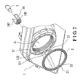
- a translucent Cap 14 is provided for each light source 3, which at its front end in known manner, a Fresnel lens or unit 141 having such is formed and arranged that the light source 3 just in focus the Fresnel lens 141 is located. This ensures that all of the Light source 3 emitted light rays nacu their passage through the Fresnel lens 141 are focused parallel to each other.
- this has a window 142.
Abstract
Description
Die Erfindung betrifft ein Umrandungshilfslicht der Lampen eines
Kraftwagens, das an einer eine Lampe umgebenden Umrandung derselben
zur Erhöhung ihrer Warnungswirkung angeordnet ist, mit mindestens einer
eigenen Lichtquelle, einer stirnseitigen ringförmigen lichtdurchlässigen
Umrandungsscheibe und einer Umrandungsaufnahme der Lampe, nach
dem Oberbegriff des Anspruchs 1.The invention relates to a border auxiliary light of the lamps
Motor vehicle, the same on a border surrounding a lamp
is arranged to increase its warning effect, with at least one
own light source, a front-side annular translucent
Border disc and a border recording of the lamp, after
the preamble of
Zur Erhöhung der Warnungswirkung einer Signallampe eines
Kraftwagens, bei der es sich um ein Standlicht, ein Bremslicht, einen
Blinker, ein Rücklicht usw. handeln kann, ist darum ein Hilfslicht
vorgesehen, das wie in Figuren 8 und 9 gezeigt eine ringförmige
Umrandungsaufnahme 41 für die Lampe 44, die in der zentraler Öffnung
derselben aufgenommen ist, eine in einer Aufnahmenut 411 der
Umrandungsaufnahme 41 aufgenommene lichtdurchlässige ringförmige
Umrandungsscheibe 42, und mindesten eine eigene Lichtquelle 43 in Form
von LED's 43 aufweist, die durch eine Gußmasse in der
Umrandungsaufnahme 41 festgelegt werden. Die Umrandungsaufnahme
411 weist eine Anzahl(in Figur 8 drei) von rotationssymmetrischen
Rasthaken 412 zu ihrer Halterung am Umfang der Lampe 44, und einen
Durchbruch 412 für die Drähte 431 für den elektrischen Anschluß der
LED's auf. Zur Streuung des Lichts aus den LED's 43 über die
Umrandungsscheibe 42 weist diese an ihrer der Umrandungsaufnahme 41
zugewandten Innenseite eine verzahnte Strukturierung auf, wodurch die
Lichtstrahlen der punktförmige Lichtquelle ein ringförmiges helliges
Umrandungsbild auf der Stirnseite der Umrandungsscheibe 42 darstellt.To increase the warning effect of a signal lamp of a
Motor vehicle, which is a parking light, a brake light, a
Turn signal, a tail light, etc., is therefore an auxiliary light
provided, as shown in Figures 8 and 9 an
Ein derartiges Umrandungshilfslicht hat die folgenden Nachteile:
Die Erfindung liegt daher die Aufgabe zugrunde, ein Umrandungshilfslicht der o.g., Gattung zu schaffen, mit dem die vorbeschriebenen Nachteile vermieden oder beseitigt werden.The invention is therefore based on the object Umreitungshilfslicht the o.g., to create genus with which the above-described disadvantages are avoided or eliminated.
Die Aufgabe wird bei einer Lampe oder einem Lampensatz eines
Kraftwagens nach dem Stand der Technik, die oder deren jede Lampe
jeweils ein sie umgebendes Hilfslicht aus einer ringförmigen
Umrandungsaufnahme mit einer zentralen Öffnung für die Lampe, einer an
der Stirnseite derselben gehaltenen lichtdurchlässigen Umrandungsscheibe
mit einer lichtstreuenden Strukturierung, und mindestens einer eigenen
Lichtquelle aufweist, erfindungsgemäß durch die kennzeichenden
Merkmale des Anspruchs 1 dadurch gelöst, daß die Lampe oder der
Lampensatz an einem Lampenhalter gehalten ist, an dem die
Umrandungsaufnahme für die oder für jede Lampe angeformt ist und der in
einem Innenraum aufgenommen ist, der durch ein dem Lampenhalter
nachgeordnetes Gehäuse und eine dem Lampenhalter vorgeordnete
lichtdurchlässige Abdeckung umschlossen ist, wobei das Gehäuse daran
angeformte Fassungen und die Umrandungsaufnahme daran angebrachte
Schlitzen jeweils für die Lichtquellen aufweist.The task is with a lamp or a lamp set of a
Motor vehicle according to the prior art, the or each of which lamp
each a surrounding auxiliary light from an annular
Edging reception with a central opening for the lamp, one on
the front side of the same held transparent bordering disc
with a light-scattering structuring, and at least one of its own
Has light source, according to the invention by the characterizing
Characteristics of
Gemäß einer vorteilhafte Weiterbildung der Erfindung ist die Stukturierung durch eine Vielzahl von halbkugelförmigen Erhebungen gebildet, die auf der der Umrandungsaufnahme abgewandten Stirnseite der Umrandungsscheibe mit gleichem Abstand voneinander angeordnet sind.According to an advantageous embodiment of the invention is the Structured by a variety of hemispherical elevations formed on the edge of the border facing away from the Umrandungsscheibe are arranged at the same distance from each other.
Eine weitere Ausgestaltung der Erfindung sieht vor, daß zur parallene Fokusierung des von einer Lichtquelle emittierten Lichtstrahls diese durch eine Kappe umschlossen wird, die an ihrem vorderen Ende eine Fresnel-linse bildet, in deren Brennpunkt die Lichtquelle liegt.A further embodiment of the invention provides that to the parallel Focusing the light beam emitted by a light source through this a cap is enclosed, which at its front end a Fresnel lens forms, in the focal point of the light source.
Schließlich ist erfindungsgemäß vorgesehen, daß zur Wärmeableitung der in der Kappe ansammelnde Wärme eine Fenster daran vorgesehen ist. Finally, the invention provides that the Heat dissipation of heat accumulating in the cap a window on it is provided.
Die Erfindung wird anhand von in der Zeichnung dargestellten Ausführungsformen näher erläutert. Es zeigen:The invention is illustrated by means of in the drawing Embodiments explained in more detail. Show it:
Figur 1 veranschaulicht einen Lampensatz mit drei Lampen, von
denen jede mit einem sie umgebenden erfindungsgemäßen
Hilfswarnungslicht versehen ist. Jedes Hilfswarnungslicht weist wie beim
Stand der Technik eine ringförmige Umrandungsaufnahme 12 mit einer
zentralen Öffnung 11 für eine Lampe, eine an der Stirnseite der
Ümrandungsaufnahme 12 gehaltene Umrandungsscheibe 2 mit einer
Strukturierung 22, und eine Anzahl (hier vier) eigene Lichtquellen 3 in
Form eines LED's auf. Die Erfindung unterscheidet sich vom Stand der
Techniki im wesentlichen darin, daß die Umrandungsaufnahmen 12 an
einem gemeinen Lampenhalter 1 angeformt sind, der in einem Innenraum
aufgenommen ist, der durch eine ihm vorgeordnete transparente
Abdeckung 15 und einem ihm nachgeordneten Gehäuse 3 begrenzt wird,
wobei das Gehäuse 13 an seiner dem Lampenhalter 1 zugewandten inneren
Seite jeweils vier Fassungen 131 für die vier LED's 3 einer Lampe aufweist,
während jede Umrandungsaufnahme 12 dementsprechend jeweils vier
durchgebrochene Schlitze 122 für den Durchtritt der von Lichtquellen
emittierten Lichtstrahlen aufweist. Zur Befestigung der
Umrandungsscheibe 2 auf der Umrandungsaufnahme 12 weist die erstere
zwei diametral gegenüberliegenden widerhakenförmige Rasthaken 21, die
jeweils in einem an der Umrandungsaufnahme 12 angebrachten Rastloch
121 eingerastet werden.Figure 1 illustrates a lamp set with three lamps, from
each with a surrounding invention
Auxiliary warning light is provided. Each auxiliary warning light is as in the case of
The prior art, an
Das von der Lichtquelle 3 emittierte Licht tritt durch die Schlitze 122
hindurch und wird durch die Strukturierung 22 zu einem helligen
ringförmigen Umrandungsbild über die Stirnseite der Umfangsscheibe 2
gestreut. Zur Verbesserung der Gleichmäßigkeit der Helligkeit ist
erfindungsgemäß die Strukturierung durch eine Vielzahl von
halbkugelförmigen Erhebungen 22 gebildet, die auf der der
Umrandungsaufnahme 12 abgewandten Stirnseite der Umrandungsscheibe
2 mit gleichem Abstand zueinander angeordnet sind. Figuren 3 und 4
illustrieren in vergrößertem Maßstab zwei mögliche Ausbildungen solcher
Strukturierung 22.The light emitted from the
Um die von einer Lichtquelle 3 emittierten Lichtstrahlen parallel zur
Lichtachse der Lampe zu fokusieren, ist jeweils eine lichtdurchlässige
Kappe 14 für jede Lichtquelle 3 vorgesehen, die an ihrem Stirnende in
bekannter Weise eine Fresnel-linse oder -einheit 141 aufweist, die derart
ausgebildet und angeordnet ist, daß die Lichtquelle 3 gerade im Brennpunkt
der Fresnel-linse 141 liegt. Hierdurch wird erreicht, daß die allen von der
Lichtquelle 3 emittierten Lichtstrahlen nacu ihrem Durchtritt durch die
Fresnel-linse 141 parallel zueinander fokusiert werden.To the light emitted from a
Um die Wärme der Lichtquelle 3 vom Inneren der Kappe 14 schnell
abzuführen, weist diese ein Fenster 142 auf.To the heat of the
Di Erfindung hat gegenüber dem Stand der Technik die folgenden
Vorteile:
Claims (4)
Priority Applications (1)
| Application Number | Priority Date | Filing Date | Title |
|---|---|---|---|
| EP04011452A EP1596124A1 (en) | 2004-05-13 | 2004-05-13 | Peripherical auxiliary light for vehicular lamps |
Applications Claiming Priority (1)
| Application Number | Priority Date | Filing Date | Title |
|---|---|---|---|
| EP04011452A EP1596124A1 (en) | 2004-05-13 | 2004-05-13 | Peripherical auxiliary light for vehicular lamps |
Publications (1)
| Publication Number | Publication Date |
|---|---|
| EP1596124A1 true EP1596124A1 (en) | 2005-11-16 |
Family
ID=34924997
Family Applications (1)
| Application Number | Title | Priority Date | Filing Date |
|---|---|---|---|
| EP04011452A Withdrawn EP1596124A1 (en) | 2004-05-13 | 2004-05-13 | Peripherical auxiliary light for vehicular lamps |
Country Status (1)
| Country | Link |
|---|---|
| EP (1) | EP1596124A1 (en) |
Cited By (1)
| Publication number | Priority date | Publication date | Assignee | Title |
|---|---|---|---|---|
| US8333493B2 (en) | 2009-04-03 | 2012-12-18 | North American Lighting, Inc. | Dual-direction light pipe for automotive lighting |
Citations (5)
| Publication number | Priority date | Publication date | Assignee | Title |
|---|---|---|---|---|
| US4949226A (en) * | 1988-06-24 | 1990-08-14 | Koito Seisakusko Co., Ltd. | Projector-type lighting device of expanded outline appearance for use as a vehicular headlamp or the like |
| US5984494A (en) * | 1995-09-08 | 1999-11-16 | Jimmy G. Cook | Light shield for an illumination system |
| DE20212478U1 (en) * | 2002-08-13 | 2002-11-21 | Der Chao Ind Co | Vehicle headlight lamp with halo effect |
| US6641295B1 (en) * | 2002-05-24 | 2003-11-04 | Wendell Ng-Sell-Quan | Fog light device |
| US6650058B1 (en) * | 2002-10-28 | 2003-11-18 | Calvin Wang | Vehicle head light or auxiliary light assembly |
-
2004
- 2004-05-13 EP EP04011452A patent/EP1596124A1/en not_active Withdrawn
Patent Citations (5)
| Publication number | Priority date | Publication date | Assignee | Title |
|---|---|---|---|---|
| US4949226A (en) * | 1988-06-24 | 1990-08-14 | Koito Seisakusko Co., Ltd. | Projector-type lighting device of expanded outline appearance for use as a vehicular headlamp or the like |
| US5984494A (en) * | 1995-09-08 | 1999-11-16 | Jimmy G. Cook | Light shield for an illumination system |
| US6641295B1 (en) * | 2002-05-24 | 2003-11-04 | Wendell Ng-Sell-Quan | Fog light device |
| DE20212478U1 (en) * | 2002-08-13 | 2002-11-21 | Der Chao Ind Co | Vehicle headlight lamp with halo effect |
| US6650058B1 (en) * | 2002-10-28 | 2003-11-18 | Calvin Wang | Vehicle head light or auxiliary light assembly |
Cited By (1)
| Publication number | Priority date | Publication date | Assignee | Title |
|---|---|---|---|---|
| US8333493B2 (en) | 2009-04-03 | 2012-12-18 | North American Lighting, Inc. | Dual-direction light pipe for automotive lighting |
Similar Documents
| Publication | Publication Date | Title |
|---|---|---|
| DE10249113B4 (en) | Vehicle lamp, in particular tail lamp, preferably for motor vehicles | |
| DE102008003929B4 (en) | vehicle light | |
| DE60130546T2 (en) | OPTIMIZED SYMBOLOGY LIGHTING DEVICE AND METHOD | |
| EP1392999B1 (en) | Pocket lamp | |
| EP1574779B1 (en) | Reflex reflector for tail-lights of vehicles | |
| DE102016119326A1 (en) | Lighting device for a vehicle | |
| EP1523431B1 (en) | Lights for motor vehicles | |
| DE2941227A1 (en) | LAMP FOR MOTOR VEHICLES | |
| DE102005036018A1 (en) | Illumination device for vehicle comprises light-conducting unit with two separate light coupling surfaces for feeding light emission of first light source to first coupling surface and second light source to second coupling surface | |
| EP1757857A1 (en) | Vehicle lamp | |
| DE19646042B4 (en) | Vehicle lighting device | |
| EP1750054B1 (en) | Lighting device for a vehicle | |
| DE102007033706A1 (en) | Vehicle lighting device consists of lighting device that has housing with chamber in which light source is located with colour changing light disc | |
| DE10124539B4 (en) | Tail light for vehicles, especially for motor vehicles | |
| EP1201497A2 (en) | Motor vehicle lighting assembly | |
| DE19758551B4 (en) | Bicycle tail light with at least two LEDs | |
| DE102004001052A1 (en) | Indication/signaling device has light source(s), focusing, transparent body(ies) for total reflection of light into horizontal plane; incident sunlight passed through surface(s) is absorbed in signal | |
| EP1702793B1 (en) | Lamp arrangement | |
| EP1596124A1 (en) | Peripherical auxiliary light for vehicular lamps | |
| DE19916843B4 (en) | vehicle light | |
| DE102013210257A1 (en) | Attachment optics for a light source | |
| DE10241023A1 (en) | Rear light for road vehicle has incandescent lamp in center of mirror behind lens with multiple refracting elements producing appearance of array of LED's | |
| EP1762777B1 (en) | Vehicule lighting unit | |
| DE102013210856B4 (en) | Light for a motor vehicle | |
| DE19838911B4 (en) | Lighting device of a vehicle |
Legal Events
| Date | Code | Title | Description |
|---|---|---|---|
| PUAI | Public reference made under article 153(3) epc to a published international application that has entered the european phase |
Free format text: ORIGINAL CODE: 0009012 |
|
| 17P | Request for examination filed |
Effective date: 20040513 |
|
| AK | Designated contracting states |
Kind code of ref document: A1 Designated state(s): AT BE BG CH CY CZ DE DK EE ES FI FR GB GR HU IE IT LI LU MC NL PL PT RO SE SI SK TR |
|
| AX | Request for extension of the european patent |
Extension state: AL HR LT LV MK |
|
| AKX | Designation fees paid |
Designated state(s): AT BE BG CH CY CZ DE DK EE ES FI FR GB GR HU IE IT LI LU MC NL PL PT RO SE SI SK TR |
|
| STAA | Information on the status of an ep patent application or granted ep patent |
Free format text: STATUS: THE APPLICATION IS DEEMED TO BE WITHDRAWN |
|
| 18D | Application deemed to be withdrawn |
Effective date: 20060829 |