The present invention relates to a body-fluid inspection device which draws
body fluids (especially, blood) by sticking a needle into the surface of a living body,
such as a finger tip, and carries out an inspection, upon inspecting body fluids such as,
for example, blood and inter-organ fluids.
Recently, along with an increase in the number of diabetics, it has been
proposed that self blood-sugar measurements be carried out by the patients so as to
monitor the every-day fluctuation of the blood-sugar value for themselves. At present,
in most of the measurements of the blood-sugar value, blood-sugar measuring devices
are used in which test paper which changes colors in accordance with the amount of
glucose in the blood is prepared, blood is supplied to the test paper so as to be
developed therein, and the blood-sugar value is estimated by optically measuring the
level of the color that has been developed (measurement of colors). Prior to this type
of measurements, the patient has to stick the skin of his or her finger tip by using a
sticking tool equipped with a needle or a small knife in order to draw and sample his or
her blood; and then the patient has to squeeze blood out by pressing the surrounding
area of the stuck portion with the fingers, etc. However, since the sticking tool and the
blood-sugar measuring device are separately provided, the patient has to replace the
sticking tool in his or her hand with the blood-sugar measuring device while the finger
is bleeding; this causes degradation in the operability, and is not preferable from the
sanitary point of view.
Here, US. Patent No. 5,279,294 discloses a system in which conventional
sticking tool and blood-sugar measuring device are provided as an integral part. In this
system, the following means are installed in a housing: a sticking means, a means for
transporting blood to a chemical reagent for use in blood and a means for carrying out
optical measurements on the chemical reagent for use in blood and for displaying the
results thereof. However, in this system, since the amount of blood is not sufficient
even if the sticking operation is carried out, the patient has to squeeze blood out by
pressing the stuck portion with the fingers, etc. after the sticking operation; this fails to
make any improvements in the operability as compared with the conventional devices.
Moreover, another blood-sugar measuring device has been disclosed in Jpn.
Pat. Appln. KOKAI Publication No. 276235 in 1997. In this blood-sugar measuring
device, a sticking means, a pressure band for pressing the finger and a means for
measuring and displaying the blood ingredients are placed in a housing. However,
although this blood-sugar measuring device makes it possible to draw a sufficient
amount of blood required by the function of the pressure band, remaining blood on the
finger tip tends to adhere to the pressure band at the time of withdrawing the finger
from the pressure band after use; this causes the possibility of contagion, etc.
Accordingly, an object of the present invention is to provide a body-fluid
inspection device which can successively carry out sticking, body-fluid (blood)
sampling and measuring processes by using simple operations.
Another object of the present invention is to provide a sticking tool which can be
suitably used also in a body-fluid inspection device of the present invention.
According to the present invention, there is provided a body-fluid inspection
device, which sticks a skin so as to obtain a fine amount of body fluids and measures
ingredients of the body fluids, comprising:
wherein the sticking means, the suction means and the measuring means are
installed inside the casing.
In the present invention, a body-fluid inspection device of the present invention
may comprise:
Also in the present invention, a body-fluid inspection device of the present
invention may comprise:
Further, in the present invention, a body-fluid inspection device of the present
invention may comprise:
wherein: an engaging section is provided in the inner face of the housing;
a stopping section is formed in at least one of the lancet, the plunger and the
stopper, the stopping section being allowed to engage the engaging section so as to
stop the lancet, the plunger and the stopper at a first position; and after the lancet, the
plunger and the stopper have shifted toward the tip end from the first position by the
spring that is released from the engagement between the engaging section and the
stopping section, the stopper comes into contact with the adjustment mechanism so
that the shift of the lancet, the plunger and the stopper is stopped at a second position.
This summary of the invention does not necessarily describe all necessary
features so that the invention may also be a sub-combination of these described
features.
The invention can be more fully understood from the following detailed
description when taken in conjunction with the accompanying drawings, in which:
Referring to Figures, the following description will discuss several preferred
embodiments of the body-fluid inspection device of the present invention.
FIG. 1 is a front view that shows one example of the body-fluid inspection
device of the present invention, FIG. 2 is a cross-sectional view of the body-fluid
inspection device shown in FIG. 1, FIG. 3 is a cross-sectional view that shows a state
in which reduced pressure is maintained in a casing in the structural examples of the
reduced-pressure releasing means and evacuation means, FIG. 4 is a cross-sectional
view that shows a state in which the reduced-pressure releasing means and the
evacuation means in the structural examples are being released from the reduced-pressure
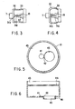
state, FIG. 5 is a plan view that shows a blood-sampling chip when viewed
from the opening section coupled to a blood-sampling chip connecting section, and
FIG. 6 is a cross-sectional view of the blood-sampling chip shown in FIG. 5. The
following explanation will be given, supposing that a body-fluid inspection device 1
measures the blood-sugar value as one ingredient of body fluids.
As illustrated in FIG. 1, the body-fluid inspection device 1 is shown as being
provided with a casing 2, a plunger cover 3, a reduced-pressure releasing button 7 for
releasing a reduced pressure state, a blood-sampling chip 10 (coupled to a blood-sampling
chip connecting section 8 in FIG. 2), a blood-sampling chip connecting
section 8 for securing the blood-sampling chip 10, a blood-sampling chip releasing
lever 6 for removing the blood-sampling chip 10, a power switch 4, a display 5 for
displaying the results of measurements, and an elastic member 9 for allowing the
blood-sampling chip 10 to be engaged and stopped by the connecting section 8 in a
vacuumed state.
As illustrated in FIG. 2, inside the casing 2 are disposed a suction sticking
mechanism consisting of a lancet 11 having a sticking needle 11a, a lancet holder 12,
a first spring 14, a plunger 15, a second spring 16, a gasket 17a, and other members,
a measuring mechanism (of which only a photoemmisive means 20 and a photoelectric
means 21 are shown), and a display mechanism (not shown).
The suction/sticking mechanism is constituted by a sticking mechanism and a
suction mechanism. As illustrated in FIG. 2, the sticking mechanism is constituted by
the lancet 11 having the sticking needle 11a, the lancet holder 12 for holding the lancet
11, an engaging member 13 that is integral with the lancet holder 12 and has an
engaging section 13a at its end, and the first spring 14 for pressing the lancet holder
12 from its rear end face, and these members 11, 12, 13 and 14 are accommodated in
a sticking-device housing 22. One end of the first spring 14 is secured to the rear end
of the lancet holder 12, while the other end is secured to a wall surface inside the
sticking-device housing 22. Here, instead of the first spring 14, an elastic member that
can push the lancet holder 12 out, such as a rubber member, may be adopted.
As illustrated in FIG. 2, the suction mechanism is, on the other hand,
constituted by the plunger 15 and the gasket 17a that is used for allowing the inside
wall of the suction housing 23 to slide along the tip end of the plunger 15 in an air-sealed
manner, and these members 15 and 17a are accommodated in the suction
housing 23.
In the body-fluid inspection device 1 as shown in the Figures, the sticking-device
housing 22 and the suction housing 23 are installed side by side, and are
designed so that the respective inner spaces communicate with each other through a
side hole 18. The tip end of the sticking-device housing 22 is in an open state, and the
blood-sampling chip connecting section 8 is placed along the tip end. The rear end
thereof is in a closed state, and the first spring 14 connecting to the lancet holder 12 is
secured to its inner surface. Here, in the present body-fluid inspection device 1, the
first spring 14 is fixed between the rear-end face of the sticking-device housing 22 and
the lancet holder 12, as shown in FIG. 2. so as to form a structure for pushing the
lancet holder 12 out; however, it may be fixed between the tip end of the sticking
housing 22 and the lancet holder 12 so as to form a structure for drawing the lancet
holder 12 out.
The suction housing 23 has a communicating hole 19 in its tip end, and the
gasket 17a, which slides along the inner wall in an air-sealed state, is sealed inside
thereof. A non-return valve 32 is installed on the outside section of the suction housing
23 so as to form an evacuation means which, upon a high pressure state inside the
sticking-device housing 22 and the suction housing 23, releases air corresponding to
the excessive pressure. Here, the communicating hole 19 and the non-return valve 32
may be installed on the side face of the suction housing 23. The plunger 15, which
extends toward the rear end of the suction housing 23, is attached to the gasket 17a.
Moreover, an O ring 17b is preferably installed along the circumferential surface of the
gasket 17a so as to enhance its sliding property and air-sealing property.
In the body-fluid inspection device 1 as shown in the Figures, the sticking-device
housing 22 and the suction housing 23 are installed in parallel with each other;
however, they may be installed in series with each other. In this case, a hole, which
corresponds to the side hole 18, is formed from the rear end of the sticking-device
housing 22 to the tip end of the suction housing 23, and the engaging section 13 is
engaged and stopped by this hole, and is released from its engagement by contacting
the gasket 17a, with the communicating hole being formed in the side face of the
housing. Additionally, when the sticking-device housing and the suction housing are
installed in series with each other, the body-fluid inspection device tends to become
longer in its entire length; however, it is possible to shorten the entire length by making
both or either of the sticking-device housing 22 and the suction housing 23 thicker and
shorter, and adjusting the respective components to be housed in the respective
housings to corresponding sizes.
Although not shown in the Figures, a rod-shaped member is installed in parallel
with the sticking-device housing 22 between the outer surface of the sticking-device
housing 22 and the inner surface of the casing 2 in such a manner that its one end is
secured to the inside of a blood-sampling chip release lever 6 on the surface of the
casing 2, while the other end is allowed to stick out by shifting the blood-sampling chip
release lever 6, and is further allowed to contact the blood-sampling chip 10 in such a
sticking-out state, so as to separate it from the blood-sampling chip connecting section
8.
Additionally, the cross-sectional shapes of the sticking-device housing 22 and
the suction housing 23 are not specifically limited, and may be formed into round,
square, or other polygon shapes. The gasket 17a is preferably formed into the same
shape as the inner-surface shape of the suction housing.
The blood-sampling chip connecting section 8 is installed in the body-fluid
inspection device 1. In FIG. 2, the blood-sampling chip connecting section 8 sticks out
from the casing 2 as a cylinder so as to surround the opening of the tip end of the
sticking-device housing 22 in the form of double circles, and the blood-sampling chip
10 is fitted thereto in a covering manner. Moreover, inside the cylindrical blood-sampling
chip connecting section 8 are installed a photoemmissive device 20 and a
photoelectric device 21 that serve as a measuring mechanism in addition to the tip end
of the sticking-device housing 22.
Moreover, as shown in FIG. 1, a ring-shaped elastic member 9 is installed
along the outer surface of the blood-sampling chip connecting section 8 in contact
therewith so as to positively engage and stop the blood-sampling chip 10 in an air-sealed
state.
The blood-sampling chip connecting section 8 is not intended to be limited to
the above-mentioned embodiment. For example, it may have a structure
that continuously extend from the tip end without surrounding the tip end of the
sticking-device housing 22, or is not necessarily provided as a structure that protrudes
from the casing 2. In other words, any structure is adopted as long as it can be fitted
to the blood-sampling chip 10 in an air-sealed state, and as long as, when reduced
pressure is applied to the sticking-device housing 22 and the suction housing 23 with
the skin of a subject being put on a suction opening 43 (see FIG. 5) of the blood-sampling
chip 10, the reduced pressure state is maintained. In this case, the shape of
the blood-sampling chip 10 is not intended to be limited to the shape as shown in
FIG. 4 or FIG. 5.
In the body-fluid inspection device 1, the photoemmissive device 20 and the
photoelectric device 21 are installed as a measuring mechanism so that the sugar
ingredient in the blood is allowed to develop colors by a color reaction through a
method that will be described later, and so that the blood-sugar value is calculated by
measuring the degree of light absorption and displayed. Here, although no specific
means for calculating the blood-sugar value and for displaying the value are shown in
the Figures, a conventional blood-sugar calculating means for calculating the blood-sugar
value by using a similar means and a conventional display means can be
adopted. Moreover, in the present invention, the measuring means is not intended to
be limited to a means for allowing the sugar ingredient in the blood to develop colors
by a color reaction as will be described later and for measuring the degree of light
absorption; and other means for making a direct contact of the sample or for
measuring the blood-sugar value by allowing light with a predetermined wavelength to
pass through the sample may be adopted. In these cases, a sensor, etc., which is
suitable for the means may be used in lieu of the photoemmissive device 20 and the
photoelectric device 21.
Referring to FIGS. 5 and 6, the following description will discuss the blood-sampling
chip 10 used in the body-fluid inspection device 1 in detail. FIG. 5 is a plan
view that shows the blood-sampling chip 10 that is viewed from an opening 45 that fits
to the blood-sampling chip connecting section 8 of the blood-sampling chip 10, and
FIG. 6 is a cross-sectional view of the blood-sampling chip 10 shown in FIG. 5.
The blood-sampling chip 10, which has a cylindrical shape, is provided with a
bottom face on its one end in which the suction opening 43 for sucking the skin upon
contact with the skin and upon reduced pressure of the sticking-device housing 22 and
the suction housing 23 is installed, and an opening 45 on the other end that fits to the
blood-sampling chip connecting section 8. Test paper 41 used for absorbing body
fluids serving as a sample is placed by the side of the suction opening 43 (in the
vicinity of the center of the bottom surface), and a groove 42 serving as a body-fluid
(blood) guiding means for guiding body fluids from the suction opening 43 to the test
paper 41 through the surface tension is also formed. In this manner, even based upon
a small amount of sampled body fluids, it becomes possible to carry out an effective
inspection. The shape, size and length of the groove 42 are not specifically limited;
and they are appropriately selected in accordance with the size and shape of the test
paper 41 and the suction opening 43. Here, in the present invention, the blood-sampling
chip 10 is not intended to be limited to the cylinder shape, and may be
provided as a square shape in its cross-section, a cylinder having a polygonal shape in
its cross-section or a conical shape whose diameter narrows toward its one end.
The diameter of the suction opening 43 is not particularly limited, and may be
set at any size as long as it is larger than a minimum size that allows the sucked skin
to form an appropriate mound shape from which blood is absorbed. Further, the shape
is not particularly limited, and may be provided as a square or another polygonal
shape. Specifically, the suction opening is preferably set so as to have an opening
diameter of 4 to 10 mm so as to come into contact with the surface of a living body,
such as the finger tip, upper arm, abdomen, thigh, and an ear-lobe and to allow a
desired blood absorbing process independent of individual differences such as sex,
age, etc. and differences in portions to be stuck; and in particular, if the portion to be
stuck is an ear-lobe, it is preferably set in the range of 4 to 6 mm. It is also preferably
formed into a shape, such as a pipe shape, which can stimulate the periphery of the
portion to be stuck when pressed onto the surface (skin) of a living body. This is
because the stimulation on the periphery of the portion to be stuck makes it possible to
alleviate pain at the time of sticking.
More specifically, as illustrated in FIG. 6, a cylinder member 46 is preferably
attached to the circumferential edge of the suction opening 43. Moreover, this cylinder
member 46 makes it possible to prevent air from flowing into the sticking-device
housing 22 and the suction housing 23 through the gap between the blood-sampling
chip 10 and the skin when the sticking-device housing 22 and the suction housing 23
are maintained in a reduced pressure state. In order to maintain visibility of the inside
of the blood-sampling chip 10, that is, in order to allow visual confirmation of the
bleeding state after the sticking operation, the blood-sampling chip 10 is preferably
constituted by a transparent or translucent material.
The shape and size of the opening 45 are not particularly limited, and any
shape and size thereof are used as long as the opening 45 is fitted to the blood-sampling
chip connecting section 8 in an air-sealed state. Additionally, it is preferable
to form a ring-shaped protrusion 44 along the inner circumferential face of the opening
45; this makes it possible to connect the blood-sampling chip 10 and the blood-sampling
chip connecting section 8 more firmly in an air-sealed state by an interactive
function with the elastic member 9 installed in the blood-sampling chip connecting
section 8.
The shape and size (including the thickness) of the test paper 41 are not
particularly limited; however, when it is too large, there may be a possibility that
measurements become inoperative in the case of a small amount of absorbed sample,
or when it is too small, the sample might not be absorbed appropriately. Taking these
into consideration, the test paper 41 is appropriately selected. The position of the test
paper 41 is not particularly limited, as long as it is close to the suction opening 43 and
allows the measuring mechanism to sense the test paper. In FIGS. 5 and 6, the test
paper 41 is located in the vicinity of the center of the bottom face with the suction
opening 43 being located on its side; however, the layout may be reversed, or the
centers of the test paper 41 and the suction opening 43 may be located in the vicinity
of the center of the bottom face.
The material and mode of the test paper 41 are not particularly limited, and
nonwoven fabric, etc. which have been conventionally used as body-fluid testing
materials may be utilized. Moreover, since the body-fluid inspection device 1 is
designed to measure the blood-sugar value (glucose concentration) by the use of a
color reaction, a reagent for allowing an enzyme such as glucose oxidase and/or its
decomposed products to develop colors is fixed to the test paper 41. In the present
invention, the measuring method is not intended to be limited to the measurements of
the degree of light absorption by the use of the color reaction, and when another
measuring method is used, the measuring mechanism may be provided with another
appropriate device, such as a sensor, instead of the above-mentioned photoemmissive
device 20 and the photoelectric device 21.
In the body-fluid inspection device 1, the communicating hole 19 is formed in
the suction housing 23 as one element of the reduced-pressure releasing means for
releasing the reduced-pressure state after a reduced pressure has been applied to the
sticking-device housing 22 and the suction housing 23 in order to suck the skin and
also to suck body fluids. Moreover, the communicating hole 19 also serves as one
element of the evacuation means which, in the case of a pressurized state of the
sticking-device housing 22 and the suction housing 23 at the time of the sticking
process, releases air corresponding to the excessive pressure.
The following description will discuss the reduced-pressure releasing means
and the evacuation means of the body-fluid inspection device 1 more specifically.
As illustrated in FIGS. 3 and 4, the reduced-pressure releasing means and the
evacuation means are integrally formed in the body-fluid inspection device 1. FIG. 3
shows a cross-sectional view of the suction housing 23 when it is in a normal state or
in a reduced-pressure state, and FIG. 4 is a cross-sectional view showing a state in
which the suction housing 23 is releasing the reduced-pressure state.
The reduced-pressure releasing means and the evacuation means are
respectively installed in a flexible housing 30. The housing 30 is provided with a
reduced-pressure releasing button 7 and a vent hole 33.
The reduced-pressure releasing means is constituted by the communicating
hole 19, a driver 31 a having a shape like the tip end of a minus screwdriver and a
wedge member 31 b attached to the base end thereof. The evacuation means is
constituted by the communicating hole 19 and the non-return valve 32. The driver 31 a
has a needle shape, and the wedge member 31 b consists of several sheets of
triangular plates. The non-return valve 32 has an opening at the top of its flexible
conical body. Here, in the present invention, the driver 31 a, the wedge member 31 b
and the non-return valve 32 are not intended to be limited to these shapes, and the
reduced-pressure releasing means and the evacuation means may be provided as
independent parts.
In the normal state or the reduced-pressure state (FIG. 3) of the suction
housing 23, the reduced-pressure releasing means is maintained in a reduced-pressure
state since the reversal stopping valve and its opening are sealed with the
driver 31 a. Thereafter, when the suction process of the skin becomes unnecessary,
the reduced-pressure releasing button 7 is depressed. This allows the driver 31 a and
the wedge member 31 b to open the non-return valve 32 in a reverse direction, with the
result that air flows into the sticking-device housing 22 and the suction housing 23 from
the vent hole 33 via the communicating hole 19, thereby releasing the reduced-pressure
state.
The evacuation means is arranged so that when the sticking-device housing 22
and the suction housing 23 are brought into a pressurized state by sliding the gasket
17a inside the suction housing 23 at the time of sticking, the non-return valve 32 is
allowed to open by the pressure so that air corresponding to the excessive pressure is
released from the communicating hole 19 via the vent hole 33.
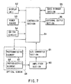
FIG. 7 shows one example of the body-fluid ingredient measuring circuit of the
body-fluid inspection device of the present invention. The measuring circuit is provided
with a control device 51 such as a CPU, and to the control device 51 are connected a
display device 52 (corresponding to the display 5 in FIG. 1), a power-source section 53
(which is connected to the power switch in FIG. 1), a switching circuit 54, a data
storage section 55 and an external output section 56. Moreover, an optical sensor 59
constituted by a photoemmissive element 57 (corresponding to the photoemmissive
means 20 in FIG. 2) and a photoelectric element 58 (corresponding to the photoelectric
means 21 in FIG. 2) is connected to the control device 51. The photoemmissive
element 57, when driven by a signal from the control device, projects light having a
given wavelength onto test paper (not shown) which has absorbed blood, and reflected
light is received by the photoelectric element 58. The received light is amplified by an
amplifier 60, and inputted to the control device through an A/D converter 61; thus, the
control device 51 calculates the blood-sugar value from the input signal based upon
data stored in the data storage section 55, and allows the display device 52 to display
the results.
The following description will discuss a method for using the body-fluid
inspection device 1.
After the lancet 11 has been attached to the lancet holder 12, the lancet holder
12 is pushed into the sticking-device housing 22 until the engaging section 13 is
engaged by the side hole 18. At this time, the first spring 24 is maintained in a
compressed state. Next, the blood-sampling chip 10 is attached to the blood-sampling
chip connecting section 8 in the main body casing 2. Then, the power switch 4 of the
body-fluid inspection device 1 is turned on. Here, the power switch may be turned on
before the blood-sampling chip 10 has been attached. Moreover, a switch may be
designed so as to automatically turn on the power upon attaching the blood-sampling
chip 10, and in this case, the power switch 4 is not required.
Next, the suction opening 43 at the tip of the blood-sampling chip is pressed
onto the skin of the subject at a portion to be stuck, and upon pressing the plunger
cover 3, the gasket 17a is shifted inside the suction housing 23 in an air-sealed state
through the plunger 15 that moves in cooperation with the plunger cover 3. When it is
pushed to reach the farthest position, the gasket 17a or the O ring 17b pushes the
engaging section 13, thereby removing the engagement; thus, the first spring 14,
which has been in a compressed state, is released so that the lancet 11 and the lancet
holder 12 is allowed to advance toward the suction opening of the blood-sampling chip
10 and carry out a sticking operation. In this case, when the sticking-device housing
22 and the suction housing 23 are brought into a pressurized state by the slide of the
gasket 17a inside the suction housing 23 in an air-sealed state, the non-return valve 32
is opened by the pressure so that air corresponding to the excessive pressure is
released from the communicating hole 19 via the vent hole 33. After the sticking
operation, the lancet holder 12 to which the lancet 11 is attached is allowed to return to
its original position corresponding to the natural length of the spring by the damping
function of the spring. In this case, it is preferable to select a spring having an
appropriate spring constant so as to prevent double sticking.
Lastly, when the pressing force is removed from the plunger cover 3 with the
suction opening 43 of the tip of the blood-sampling chip being pressed onto the skin,
the gasket 17a is allowed to retreat by the function of the second spring 16 through the
plunger 3 that moves in cooperation with the plunger cover 3, thereby bringing the
sticking-device housing 22 and suction housing 23 into a reduced-pressure state so
that body fluids are sucked from the stuck portion. Here, the minimum pressure inside
the space in the reduced-pressure state is preferably set at approximately -300 mmHg
with respect to the atmospheric pressure. This makes it possible to suck a required
amount of body fluids in a short time. Then, the body fluids sucked onto the skin are
transmitted through the guiding groove 42 formed in the inner wall of the blood-sampling
chip 10 by the capillary phenomenon, and absorbed into the test paper 41.
Thereafter, light having a given wavelength is projected from the
photoemmissive means 20 onto the blood absorbed in the test paper 41, the reflected
light is sensed by the photoelectric means 21, the blood-sugar value is measured, and
the results are displayed on the display 5. Additionally, after the blood has been
absorbed in the test paper 41, the reduced-pressure releasing button 7 is pressed so
that external air is introduced into the sticking-device housing 22 and the suction
housing 23, and the body-fluid inspection device 1 is removed when the sense of being
sucked disappears from the skin.
As described above, the present invention provides a body-fluid inspection
device in which a sticking tool and a measuring device for a body-fluid ingredient (for
example, blood-sugar value) are formed into an integral device. As compared with the
application of conventional sticking tool and body-fluid measuring device, the body-fluid
inspection device of the present invention provides an efficient operation and is
superior in sanitation. Moreover, the body-fluid inspection device of the present
invention carries out a suction operation on the periphery of a portion to be stuck on
the skin of the subject, with the inside of the device being maintained in a reduced-pressure
state so as to accelerate the flow of body fluids; therefore, even with
superficial sticking with less pain, an amount of body fluids required for an inspection,
etc., can be readily obtained, and measured.
Next, referring to FIGS. 8 through 13, an explanation will be given of one
example of a sticking tool that is preferably used in the body-fluid inspection device of
the present invention. FIGS. 8, 9, 10 and 11 are cross-sectional side views that show
the sticking tool of the present invention in respectively different states; and FIG. 12
and FIG. 13 are cross-sectional views that show a structural example of the air-releasing
means. Here, upon explanation, in FIGS. 8 through 11, the upper side is
referred to as "base end" and the lower side is referred to as "tip end".
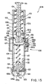
As illustrated in FIGS. 8 through 13, the present sticking tool (blood-sampling
sticking tool) 101 A is provided with a housing 102, a sticking plunger 103, a coil spring
(first pressing means) 104 for pressing the sticking plunger 103 in the tip-end direction,
a suction plunger 105, a coil spring (second pressing means) 106 for pressing the
suction plunger 105 in the base-end direction, an air-releasing valve (air-releasing
means) 107 and an operation means 108.
The housing 102 is constituted by a cylinder-shaped housing main body 121
and a cap 122 that is attached to the tip end of the housing main body 121 so as to be
freely detached. The housing main body 121 and the cap 122 are made of a material
that virtually does not transmit air.
Moreover, a seal ring 123, made of an elastic material, is inserted and
sandwiched between the housing main body 121 and the cap 122 so that the cap 122
is attached to the housing main body 121 in an air-sealed state.
The housing main body 121 is designed to house the sticking plunger 103
which will be described later in detail, the coil spring 104, the suction plunger 105 and
the coil spring 106, and also serves as a holding portion when the sticking tool 101 A is
used.
The cap 122, which is a tube-shaped member, has a taper section 122b that
narrows its inner and outer diameters toward the tip end.
The tip end of the cap 122 is a portion that is to come into contact with the
surface of a living body, such as, for example, the finger tip, upper arm, abdomen,
thigh or ear-lobe, and is provided with a tip opening 122a. This tip opening 122a has
its opening diameter (opening area) properly adjusted so that a desired suction blood
sampling can be carried out independent of individual differences such as sex, age,
etc. and differences in portions to be stuck. Specifically, the opening diameter of the
tip opening 122a is preferably set in the range of 4 to 10 mm, and is more preferably
set in the range of 4 to 6 mm in the case when the finger or ear-lobe is used as the
portion to be stuck.
The outer edge of the tip end of the cap 122 is formed into a shape that is
suitable for stimulating the periphery of the portion to be stuck and for alleviating pain
at the time of sticking when it is pressed onto the surface of a living body (the skin).
The shape is also suitable for preventing air from flowing into the housing 102 between
the cap 122 and the surface of a living body when the housing 102 is in a reduced-pressure
state.
In order to maintain visibility of the inside, more specifically, in order to allow
visual confirmation of the bleeding state after the sticking operation, the cap 122 is
preferably made of a transparent or translucent material.
An opening 124 through which the suction plunger 105 is inserted is formed at
the base end of the housing main body 121. Moreover, side holes 125 and 126, which
respectively correspond to a sticking- and suction-use operation button 184 and an air-releasing-use
operation button 186 that will be described later, are formed in the side
wall of the housing main body 121.
Furthermore, a partition plate 127 is placed inside the housing main body 121.
The partition plate 127 is fixedly secured to the side wall of the housing main body 121,
or is integrally formed therewith.
A guide groove 128 is formed in the side-wall inner surface of the housing main
body 121 in the length direction of the housing main body 121. A stopper 129 with
which a protruding portion 134 comes into contact is formed at the tip end of the guide
groove 128 (see FIG. 9).
A sticking mechanism, constituted by the sticking plunger 103 and the coil
spring 104 for pressing the sticking plunger 103 toward the tip end, is placed inside the
housing main body 121.
The sticking plunger 103 is constituted by a needle holder (lancet holder) 131 to
which the lancet 111 having the sticking needle 112 is detachably attached, an elastic
member 132 that is integrally formed with the needle holder 131 with a first engaging
section 133 provided at its end (on the base-end side), and a protruding portion 134
that is integrally formed with the needle holder 131.
The first engaging section 133 is pressed to the right in FIG. 8 by the elastic
force of the elastic member 132, and is engaged by the edge of the side hole 125;
thus, the sticking plunger 103 is restricted in its shift toward the tip end.
When the sticking tool 101 A is not used (in a state prior to sticking), the coil
spring 104 is in a compressed state, and its respective ends are secured to the
partition plate 127 and the base-end face of the needle holder 131 so that the sticking
plunger 103 is pressed toward the tip end.
The protruding portion 134 is inserted into the guide groove 128, and allowed to
slide in the length directions of the guide groove 128. Thus, the sticking plunger 103 is
shifted inside the housing 102. In this case, the protruding portion 134 comes into
contact with the stopper 129, thereby restricting the sticking plunger 103 in its shift
toward the tip end. In other words, the setting position of the stopper 129 makes it
possible to adjust the sticking depth on the surface of a living body by the sticking
needle 112 (= maximum protruding length of the sticking needle 112 from the tip
opening 221) (see FIG. 9).
Additionally, the coil spring 104 is properly set so as to have an appropriate
elastic coefficient (spring constant) so as not to again stick the surface of a living body
during its damping movements after the sticking needle 112 has stuck the surface of
the living body.
Moreover, a suction mechanism (negative-pressure generation mechanism),
which is constituted by the suction plunger 105 and the coil spring 106 for pressing the
suction plunger 105 toward the base end, is installed in the housing main body 121.
The suction plunger 105 is a rod-shaped member, and provided with a handling
section 151 on its base end and a gasket 152 on its tip end. The gasket 152 has a
seal ring (sealing member) 153 made of an elastic material along its peripheral portion.
The seal ring 153 contacts the inner circumferential face of the housing main
body 121 in an air-sealed state, and when the suction plunger 105 is shifted in a length
direction of the housing main body 121, the seal ring 153 also shifts in the same
direction along the inner circumferential face of the housing main body 121 in an air-sealed
state. In this case, the seal ring 153 is preferably set to exhibit a sliding
resistance to a degree not to disturb the expansion and shrinkage of the coil spring
106.
An elastic member 154, which is elastically deformable, is formed on the side
face of the gasket 152 in a protruding manner, and a second engaging section 155 is
formed on its tip end. The second engaging section 155 is pressed to the right in
FIG. 8 by the elastic force of the elastic member 154, and is engaged by the edge of
the side hole 125; thus, the suction plunger 105 is restricted in its shift toward the base
end.
The respective ends of the coil spring 106 are fixed to the base end of the
housing main body 121 and the gasket 152. When the sticking tool 101 A is not used
(in a state prior to sticking), the coil spring 106 is in an extended state so that the
suction plunger 105 is pressed toward the base end by its elastic force.
In the suction plunger 105, the seal ring 153 of the gasket 152 contacts the
inner circumferential face of the housing main body 121 in an air-sealed state, and the
side holes 125 and 126 are also sealed in an air-sealed state; therefore, when the
suction plunger 105 is shifted toward the base end with the tip opening 122a being
sealed on the surface of a living body, a space 110 inside the housing 102, surrounded
by the housing 102 and the gasket 152, is brought to a reduced-pressure state
(negative-pressure state).
The air-releasing means is used for releasing the space 110 inside the housing
102 kept in the reduced-pressure state to the atmospheric pressure, and in the present
embodiment, it is provided as an air-releasing valve 107 that is manually opened and
closed.
As illustrated in FIG. 12 and FIG. 13, the air-releasing valve 107 is constituted
by a disc-shaped valve member 171 that is connected to or integrally formed with the
shaft 186a of the operation button 186, an elastic member 172 which has a C-lefter
shape (a shape of a ring with a cut-out in its one portion) and presses the operation
button 186 and the valve member 171 to the right in FIG. 1, and a ring-shaped seal
pad (seal member) 173 which is secured to the valve member 171 and made of an
elastic material.
As illustrated in FIGS. 8 and 12, in a state where the operation button 186 is left
untouched, the operation button 186 and the valve member 171 are pressed to the
right in FIG. 8 and FIG. 12 by the elastic force of the elastic member 172; thus, the
seal pad 173 is pressed and comes into contact with the inner face of the housing
main body 121 located on the periphery of the side hole (vent opening) 126 so that the
side hole 126 is sealed in an air-sealed state.
As illustrated in FIG. 11 and FIG. 13, when the operation button 186 is pressed
to the left in FIG. 11 and FIG. 13 by the finger, etc. against the elastic force of the
elastic member 172, the operation button 186 and the valve member 171 are shifted in
the same direction, and the seal pad 173 is separated from the peripheral portion of
the side hole 126 so that a gap is formed. Consequently, the space 110 is allowed to
communicate with the outside air through the side hole 126, the cut-out of the elastic
member 172 and the button-inserting holes 182 and 183, thereby allowing the air to
flow therein.
In this case, the elastic member 172 is set so as to have an appropriate
elasticity (rubber hardness) so that it is hardly deformed when the space 110 is
brought to a reduced-pressure state by the operation of the suction plunger 105 and a
force is exerted on the valve 171 to the left in FIG. 8 due to the pressure difference
over the atmospheric pressure, and so that upon depression of the operation button
186 by the finger, etc., a predetermined amount of deformation is made, thereby
allowing the seal pad 173 to separate from the inner face of the housing main body
121 on the periphery of the side hole 126 and to form the gap.
With respect to the constituent material of the elastic member 172, for example,
the following materials are listed: various rubber materials, such as natural rubber,
isoprene rubber, butadiene rubber, styrene-butadiene rubber, nitril rubber, chloroprene
rubber, butyl rubber, acrylic rubber, ethylene-propylene rubber, hydrine rubber,
urethane rubber, silicone rubber and fluorine-containing rubber, and various elastmers,
such as styrene, polyolefin, polyvinyl-chloride, polyurethane, polyester, polyamide,
polybutadiene and fluorinated elastmers. Further, various springs such as coil springs
may be used as the elastic member 172.
The operation means 108 carries out the following operations: (1) a sticking
operation which is made by the sticking needle 112 on the surface of a living body
through the operation of the sticking plunger 103; (2) a pressure-reducing operation
applied to the space 110 by the operation of the suction plunger 105; and (3) a
releasing operation applied to the space 110 so as to release the reduced-pressure
state to the atmospheric pressure. It is constituted by a cover (case) 181 for housing
the housing main body 121, the sticking- and suction-use operation button 184, the
pressing member 185 and the air-releasing operation button 186.
The above-mentioned operations (1) and (2) are carried out simultaneously, or
successively in this order by the pressing of the operation button 184, and the above-mentioned
operation (3) is carried out by the pressing of the operation button 186
independently from the operations.
The cover 181 also has a function for housing and maintaining the operation
buttons 184 and 186. In other words, button-inserting holes 182 and 183 are formed in
the cover 181 so that the operation button 184 and the operation button 186 are
respectively inserted through the button-inserting hole 182 and the button-inserting
hole 183.
The pressing member 185, placed on the backside of the operation button 184,
is constituted by a plate-shape member made of an elastic material such as a rubber
material, and is fixedly bonded from the outside of the housing 121 in a manner so as
to seal the side hole 125 in an air-sealed manner. Therefore, the pressing member
185 also has a function as a sealing member.
Inside the pressing member 185 are formed a first protruding portion 185a and
a second protruding portion 185b that protrude toward the inside of the side hole 125.
The first protruding portion 185a contacts the first engaging section 133, and the
second protruding portion 185b contacts the second engaging section 155. In this
case, the height (the length of protrusion) of the first protruding portion 185a is set to
be greater than the height (the length of protrusion) of the second protruding portion
185b.
The pressing member 185 is deformed in cooperation with the pressing
operation of the operation button 184 in a lateral direction in FIG. 8. More specifically,
when the operation button 184 is pressed to the left in FIG. 8 by the finger, etc., with
the first engaging section 133 and the second engaging section 155 being engaged by
the edge of the side hole 125 (see FIG. 8), the pressing member 185 is also
depressed in the same direction so that the first protruding portion 185a and the
second protruding portion 185b are deformed so as to protrude further into the side
hole 125 (see FIGS. 9 and 10). Consequently, the first engaging section 133 and the
second engaging section 155 are pressed to the left in FIGS. 9 and 10 against the
elastic force of the elastic members 132 and 154, and thereby shifted. At this time,
since there is a difference between the heights of the first protruding portion 185a and
the second protruding portion 185b, the first engaging section 133 is first disengaged
from the edge of the side hole 125, and the second engaging section 155 is then
disengaged from the edge of the side hole 125, in accordance with the pressing
operation of the operation button 184.
When the finger is removed from the operation button 184, the pressing
member 185 and the operation button 184 are returned to their original states (states
shown in FIG. 8) by the restoring force of the pressing member 185.
In the sticking tool 101A, the pressing direction of the operation button 184, that
is, the operation direction in which the sticking plunger 103 is operated and allowed to
stick, and the shifting direction (the sticking direction) of the sticking plunger 103 are
set in different directions (directions virtually orthogonal to each other). This makes it
possible to alleviate fear of the sticking operation, and also to keep unchanged the
contact pressure of the tip end of the cap 122 onto the surface of a living body applied
by the pressing force of the operation button 184, thereby ensuring a predetermined
depth of the sticking operation.
Next, an explanation will be given of the operation of each of the parts carried
out in the sticking operation of the
sticking tool 101 A.
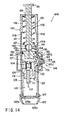
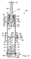
FIGS. 14 through 17 are cross-sectional side views that respectively show
another embodiment of the sticking tool of the present invention, and FIGS. 18 through
21 are cross-sectional views that respectively show a structural example of an air-releasing
means.
The following description will discuss a sticking tool 101 B shown in these
drawings based upon distinctions from the above-mentioned sticking tool 1 01 A, and
with respect to the same operations, the description thereof is omitted. Here, in
FIGS. 14 through 17, upon explanation, the upper side is referred to as "base end",
and the lower side is referred to as "tip end".
The sticking tool 101 B is provided with an air-releasing means which is
automatically operated in accordance with the shift of the suction plunger 105 toward
the base end.
The plunger 105 in the sticking tool 101 B is provided with an inner space (vent
path) 156 that penetrates from its base end to its tip end. Moreover, a flange 157 is
formed at a position on the base end side from the air-releasing valve 109 of the
suction plunger 105, and the tip end of the coil spring 106 is secured to the flange 157.
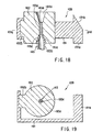
The air-releasing valve (air-releasing means) 109 is installed in the suction
plunger 105. As illustrated in FIGS. 18 through 21, the air-releasing valve 109 is
constituted by an operation member 191 having an inverted letter C-shape when
viewed from the top, a seal member 192 secured to one end of the operation member
191 and a tube body 193 having a vent inlet 193d. A head portion 191 a is attached to
the other end of the operation member 191, and a slanting slope 191 b is formed in the
head portion 191 a.
The seal member 192 is made of an elastic material as described earlier, and a
vent path 192a having a narrow-diameter section is formed in the center thereof. As
illustrated in FIG. 18, the upper end of the vent path 192a communicates with an inner
space 156 formed in the suction plunger 105 on the base-end side from the flange
157.
Furthermore, a fitting section 192b is formed in the seal member 192, and the
fitting section 192b is fitted to one end of the operation member 191 and fixedly
bonded thereto. The portion of the seal member 192, which is opposite to the fitting
section 192b with the vent path 192a located in between, is secured to the suction
plunger 105, and is maintained in an immovable state against the shift of the operation
member 191.
The tube body 193, which is inserted into the vent path 192a, is provided with a
small-diameter section 193a and a large-diameter section 193b, and a taper section
193c that connects these sections. A vent opening 193d which allows the inside and
outside of the tube body 193 to communicate with each other is formed in the taper
section 193c. The small-diameter section 193a and the taper section 193c of the tube
body 193 closely contact the inner face of the vent path 192a with the seal member
192 sandwiched along all circumferential area thereof (see FIG. 18 and FIG. 19).
The end of the large-diameter section 193b of the tube body 193 is inserted into
the inner space 156 formed inside the gasket 152 so that the inside of the tube body
193 and the inner space 156 are allowed to communicate with each other.
A fine flow-path 193e for ensuring a fine amount of ventilation is formed inside
the small-diameter section 193a of the tube body 193. The fine flow-path 193e
communicates with the vent path 192a.
Here, with respect to the constituent material of the tube body 193, any of hard
materials such as a hard resin and a metal material, soft materials such as a soft resin
and elastic materials as described earlier, may be applied; however, it is preferable to
use hard or soft resin materials.
Next, an explanation will be given of the operation of the air-releasing valve
109.
As illustrated in FIG. 18 and FIG. 19, in a state in which the head section 191 a
is not subjected to a pressing force, the small-diameter section 193a and the taper
section 193c of the tube body 193 closely contact the inner face of the vent path 192a
with the seal member 192 sandwiched along all the circumferential area thereof. This
blocks the vent opening 193d, making a state in which the inner spaces 56 are virtually
shielded from the air flow (a state in which the air-releasing valve 109 has been
closed). Here, although the inner spaces 156 at the respective ends of the air-releasing
valve 109 communicate with each other through the fine flow-path 193e, this
hardly gives any effect in bringing the space 110 to a reduced-pressure state since the
amount of air allowed to pass through it is very small.
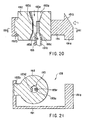
As illustrated in FIG. 20 and FIG. 21, when a pressing force is applied to the
head section 191a to the left in the drawing, the seal member 192 is pulled in the same
direction at its fitting section 192b, and deformed so that the vent path 193a is
expanded. Thus, a gap is formed between the small-diameter section 193a and the
taper section 193c of the tube body 193 and the inner face of the vent path 192a,
thereby making a state in which the vent opening 193d is opened (a state in which the
air-releasing valve 109 is opened). Thus, the inner spaces 156 at the respective ends
of the air-releasing valve 109 are allowed to communicate with each other through the
vent path 193a, the vent opening 193d and the inside of the tube body 193 so that air
flow is available. When the air-releasing valve 109 is opened in a reduced-pressure
state of the space 110, air flows into the space 110 through paths indicated by arrows
in FIG. 20.
When the pressing force, applied to the head section 191a, is removed, the
seal member 192 is returned to its original shape as shown in FIG. 18 and FIG. 19 by
its restoring force, resulting in a state in which the air-releasing valve 109 is again
closed.
The air-releasing valve 109 also serves as a relief valve which, upon having a
pressurized state in the space 110 due to the shifting operation of the suction plunger
105 toward the tip end, releases air corresponding to the excessive pressure. In other
words, when the space 110 is brought into a pressurized state with the air-releasing
valve 109 being closed (a state shown in FIG. 18 and FIG. 19), the air inside the space
110 is externally released through the fine flow-path 193e of the tube body 193 little by
little.
A slanting face (cam face) 121 a, which engages the slanting face 191 b of the
head section 191 a, is formed in the inner face on the base-end side of the housing
main body 121. When the suction plunger 105 is shifted toward the base end and the
slanting face 191 b of the head section 191 a comes into contact with the slanting face
121 a, and slides thereon (see FIG. 16), the slanting face 191 b is pushed toward the
center axis (to the left in FIG. 16) of the suction plunger 105, the operation member
191 is shifted in the same direction, and the air-releasing valve 109 is opened based
upon the operational principle as described earlier.
Moreover, a step-gap section 121 b is formed in the inner face on the base-end
side of the housing main body 121, which is the side opposite to the slanting face
121 a. The step-gap section 121 b engages the outer circumferential portion on the
base-end side of the gasket 152 so as to restrict the shift of the suction plunger 105
toward the base end.
The opening of the air-releasing valve 109, which is made when the slanting
face 191 b passes through the slanting face 121 a, takes place immediately before the
gasket 152 is engaged by the step-gap section 121 b, that is, immediately before the
suction plunger 105 has arrived at the limit position of shift on the base-end side.
The time that is taken from the release of the engaging section 155 from the
edge of the side hole 125 to the opening of the air-releasing valve 109 is set as a time
period that sufficiently allows an amount of blood required to be sucked through the
portion that has been stuck by the sticking needle 112; and, for example, this is
preferably set in the range of 3 to 10 seconds. This time can be set appropriately by
selecting factors, such as the spring elasticity of the coil spring 106, the sliding
resistance of the seal ring 153 against the inner face of the housing main body 121,
the shift stroke of the suction plunger 105 and the installation position of the slanting
face 121 a. For example, the time can also be adjusted by exchanging the coil spring
106 and/or the seal ring 153.
A stopper 129a with which the tip face of the needle holder 131 comes into
contact is formed in the inner face of the tip end of the housing main body 121. The
stopper 129a is secured to the inner surface of the housing main body 121, for
example, by means of threads, and can be adjusted in its position in the length
direction with respect to the housing main body 121 by the amount of revolutions of the
threads. In this manner, the amount of protrusion of the sticking needle 112, that is,
the depth of sticking into the surface of a living body, can be adjusted depending on
individual differences in the person whose blood is to be sampled (the subject) and
differences in the portion to be stuck.
Here, with respect to the threading structure (not shown) of the stopper 129a to
the housing main body 121, for example, the gear structure of a micrometer may be
adopted. Moreover, it is preferable to adjust the depth of sticking of the sticking needle
112 by the unit of 0.1 mm or in a stepless manner.
Next, an explanation will be given of the operation of each of the parts in
carrying out the sticking operation by using the
sticking tool 101 B.
In the sticking tool 101 B, after the suction process, the pressure inside the
housing 102 is automatically returned to the atmospheric pressure, without the need
for the operation of the person whose blood is to be sampled (the subject), etc.;
therefore, it is possible to reduce dispersions in the amount of sampled blood resulting
from an erroneous judgement on the timing for the return to the atmospheric pressure,
and also to prevent scattering of blood due to the fact that the operator forgot to return
the pressure to the atmospheric pressure. Consequently, a more appropriate blood
inspection is available.
FIGS. 22 through 25 are cross-sectional side views that respectively show
another embodiment of the sticking tool of the present invention.
The following description will discuss a sticking tool 101C shown in these
drawings based upon distinctions from the above-mentioned sticking tool 101 A, and
with respect to the same operations, the description thereof is omitted. Here, in
FIGS. 22 through 25, upon explanation, the upper side is referred to as "base end",
and the lower side is referred to as "tip end".
Merely by pressing the operation button 184, the sticking tool 101C makes it
possible to carry out the sticking operation by the use of the sticking needle 112, the
suction operation (reduction of the pressure in the space 110) and the releasing
operation of the space 110 to the atmospheric pressure in this order.
A branch path 194, which communicates with the space 110, is formed in the
side of the housing main body 121. The branch path 194 is housed in the cover 181.
The air-releasing valve (air-releasing means) 109 which is the same as that of the
sticking tool 101 B is installed at the end of the branch path 194 in a manner so as to
seal (shield) the inside of the branch path 194.
Moreover, a lever 184a is attached to the operation button 184 in a manner so
as to stick in a direction orthogonal to the shifting direction of the operation button 184.
When the operation button 184 is pressed and shifted to the left in FIG. 22, the
engagements of the first engaging section 133 and the second engaging section 155
are successively removed, and the lever 184a is then allowed to contact the head
section 191 a, thereby pressing the pressing member 191 in the same direction so that
the air-releasing valve 109 is opened based on the operational principle as described
earlier (see FIG. 25).
Furthermore, the sticking tool 101C is provided with the same stopper 129a as
described earlier on the inside of the tip end of the housing main body 121.
Next, an explanation will be given of the operation of each of the parts in
carrying out the sticking operation by using the
sticking tool 101C.
In the sticking tool 101C, merely by pressing the operation button 184, it is
possible to carry out the sticking operation by the use of the sticking needle 112, the
suction operation and reduction of the pressure in the space 110 and the releasing
operation of the space 110 to the atmospheric pressure in this order; this ensures
superior operability.
The above descriptions have discussed the sticking tools of the present
invention based upon the respective embodiments illustrated by the drawings,
however, the present invention is not intended to be limited by these, and, for example,
the structure of each part may be replaced by any structure capable of achieving the
same functions.
Moreover, the above descriptions have discussed the case in which blood is
sampled; however, the sticking tools of the present invention are not intended to be
limited thereby. For example, they may be used for sampling body fluids other than
blood, such as inter-organ fluids, and the application is not particularly limited.
In accordance with the sticking tools of the present invention that have been
discussed referring to FIGS. 8 through 25, the suction process is carried out on the
periphery of the portion that has been stuck so as to accelerate the flow of body fluids
(bleeding); therefore, it is possible to ensure to obtain an amount of body fluids
required for an inspection, etc. quickly, even if only a shallow sticking is made so as to
reduce pain.
Moreover, the mechanism for releasing the inside of the housing so as to return
the pressure to the atmospheric pressure after the suction process is provided;
therefore, it is possible to prevent scattering of the body fluids due to a rapid air flow
occurring in the proximity of the portion that has been stuck. In particular, since such
an air-releasing operation is carried out without the need for the shift of the sticking
needle (coming close to the surface of a living body), it is possible to prevent an
erroneous sticking recurring on the surface of the living body, and consequently to
provide a highly safe device.
Furthermore, the sticking operation and the suction operation are carried out in
this order or at the same time, and the air-releasing operation is then carried out
successively. These operations are extremely simple, and it is possible to provide an
appropriate depth of sticking by the sticking needle, and consequently to ensure an
amount of body fluids required merely by giving a minimum pain.
In particular, in the case when the mechanism for adjusting the depth of
sticking is installed, the depth of sticking can be appropriately adjusted depending on
various conditions, such as individual differences and differences in the portion to be
stuck, and every time a body-fluid sampling (blood sampling) operation is performed, a
constant depth of sticking is provided.
Moreover, preparation operations prior to use, that is, operations for setting the
sticking plunger and suction plunger in an operative state, are simple and easy; this is
advantageous when the device is used regularly or repeatedly.
Furthermore, since the sticking needle is designed not to protrude from the tip
opening except for the sticking operation, it is possible to prevent accidents such as an
erroneous sticking; this ensures a highly safe device. In addition, since the sticking
needle is not directly visible, it is possible to alleviate fear of sticking.
In the case when the sticking direction of the sticking needle and the operation
direction of the sticking operation are made different from each other, the force applied
by the operation upon sticking is not exerted on the surface of a living body; therefore,
it is possible to ensure a more stable sticking operation, to achieve a depth of sticking
as has been preset, and also to alleviate fear of sticking.
As described above, the sticking tool of the present invention is suitable for
cases in which the patient measures his or her own blood-sugar value, etc.
Moreover, the sticking tool of the present invention has a simple structure and
is suitable for mass production.
Referring to FIGS. 26 through 39, the following description will discuss still
another embodiment of the sticking tool of the present invention in detail.
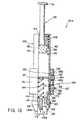
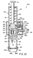
A sticking tool 201 whose cross-section is shown in FIG. 26 is mainly used for
sampling a fine amount of body fluids, such as blood, from the surface of a living body.
The sticking tool 201 is constituted by a housing 202, a plunger 203 which slides inside
the housing 202, a lancet 204 which is attached to the tip end of the plunger 203 and
has a sticking needle 241 that extends toward the tip end, a stopper 205 connected to
the rear end of the plunger 203, an adjusting mechanism 210 that contacts the stopper
205, and a sticking-use spring 206 used for shifting the plunger 203, the lancet 204
and the stopper 205 toward the tip. An engaging section 8 is installed on the inner
face of the housing 202, and a stopping section 207, which engages the engaging
section 208 so as to stop the plunger 203, the lancet 204 and the stopper 205 at a first
position, is installed in the plunger 203.
Here, the first position refers to a state prior to the sticking operation onto the
surface of a living body, and is shown in FIG. 26 more specifically.
The shape of the housing 202 is not particularly limited as long as it has a
cylindrical shape as shown in FIG. 26; however, from the viewpoint of ease of gripping,
it is preferable to provide it as a cylinder. Moreover, it is more preferable to provide a
flat section 221 shown in a plan view of FIG. 29 on the periphery of the engaging
section 208, because the engagement between the stopping section 207 and the
engaging section 208 can be easily released without the need for observing it, merely
by sliding the finger along the flat section 221.
The sticking-use spring 206, one end of which is connected to the plunger 203
and the other end of which is connected to a sticking-use spring fixing base 209
installed inside the housing, is inserted in a compressed state. However, the present
invention is not intended to be limited to this structure, and one end may be connected
to the lancet 204 or the stopper 205, while the other end may be directly connected to
the inner face of the housing 202. Moreover, with respect to the sticking-use spring
206, any spring may be used as long as it allows the plunger 203, lancet 204 and
stopper 205 to shift to the first position to the second position, and the shape thereof is
not particularly limited; for example, in addition to a coil-shape spring as shown in the
drawing, a plate-shape spring, etc. may be adopted, and the material thereof is not
particularly limited. Here, at the first position, the sticking-use spring 206 is in a
compressed state.
Here, the second position refers to a position at which the sticking needle 241
sticks the surface of a living body, and in this case, the state is not limited to a state in
which the sticking needle protrudes from the tip end of the sticking tool 201 and, for
example, it includes a state in which the tip end of the sticking tool 201 is pressed onto
the surface of a living body so as to be ready for sticking, with the surface of the living
body swells inside the tip end.
The stopping section 207 is installed in the plunger 203; however, the present
invention is not intended to be limited to this structure, and it may be installed in the
lancet 204 or the stopper 205. With respect to the shape thereof, instead of securing
one end to the plunger 203, etc., a shape, such as a U-letter shape or a V-letter shape,
for allowing both of the ends to be secured to the plunger 203, etc. may be adopted.
In other words, any shape may be adopted as long as the plunger 203, the lancet 204
and the stopper 205 are stopped at the first position by the engagement with the
engaging section 208 and the engagement with the engaging section 8 can be
released by a movement. Moreover, in the case of the engaging section 208 that
penetrates the housing 202 from the inner face to the outer face, which will be
described later, it is preferable to design the stopping section 207 so that one portion
thereof protrudes from the outer face of the housing 202 through the engaging section
208, from the viewpoint of the operation for releasing the engagement.
The engaging section 208 is not particularly limited as long as it engages the
stopping section 207 installed on the inner face of the housing 202; however, it is
preferable to provide it as a hole penetrating the housing 202 from the inner face to the
outer face as is shown in the present embodiment. With this structure, it is possible to
ensure the engagement with the stopping section 207, and also to easily release the
engagement by pushing the stopping section 207.
The stopper 205 is connected to the rear end of the plunger 203 and provided
with a stopper-side shift restriction mechanism 251. The stopper-side shift restriction
mechanism 251 engages an adjustment-mechanism-side shift restriction mechanism
210a so that the plunger 203, the lancet 204 and the stopper 205, which have shifted
from the first position, are stopped at the second position. Here, in the present
embodiment, the stopper-side shift restriction mechanism 251 and the adjustment-mechanism-side
shift restriction mechanism 101 are both provided as protrusions;
however, the structures are not particularly limited, and another structure may be
adopted in which one is provided as a protrusion and the other is provided as a recess,
or in which the inner diameter or the outer diameter is gradually changed in the axial
direction in both of the mechanisms so that they make a taper-shape engagement.
Moreover, the stopper 205 is not necessarily provided as a member separated from
the plunger 203 as described in the present embodiment, and it may be provided as an
integral part of the plunger 203.
Since the lancet 204 is placed apart from the stopper 205, a shock, which is
transmitted to the lancet when the plunger 203, the lancet 204 and the stopper 205
have been stopped at the second position from the first position, can be damped by
the stopper 205. In other words, different from a conventional mechanism, since the
lancet is not directly restricted in its movement, the shock is not directly transmitted to
the lancet; therefore, it is possible to prevent an accidental separation of the sticking
tool 1 from the hand of the operator by the shock, trembling of the sticking operation
and unnecessary pain being given to the person whose body fluids are sampled.
With respect to the adjustment mechanism 210, any mechanism can be
adopted as long as it is movable in the axial direction inside the housing 202 as shown
in FIG. 26, with the stopper 205 being allowed to move inside thereof, and more
specifically, one having a cylinder shape may be adopted. The above-mentioned
adjustment-mechanism-side shift restriction mechanism 210a is installed in the
adjustment mechanism 210. Moreover, it is preferable to design the adjustment
mechanism 210 so as to have an uninserted portion 210b with respect to the housing
202, and with this arrangement, a driving force for axially rotating the adjustment
mechanism 210 can be transmitted.
The uninserted portion 210b is preferably covered with a protection cover 211
so as to prevent the adjustment mechanism 210 from being shifted from the set
position due to an erroneous operation. In this case, the protection cover 11 is
preferably designed so as to have a structure and a material property in which the
uninserted portion 210b is not rotated unless the operator intends to do so. For
example, it may be removable upon operation of the uninserted portion 210b or it may
have flexibility so as to allow the operator to pinch the uninserted portion 210b and to
axially rotate it.
In the present embodiment, the adjustment mechanism 210 has a structure
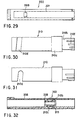
whose front view is shown in FIG. 30 and whose plan view is shown in FIG. 31.
Specifically, a helical groove 210d is formed on the peripheral portion thereof. This
groove 210d allows a protruding member 212b installed in a connecting section which
will be described later to relatively move along the inside thereof.
Moreover, in the present embodiment, as illustrated in FIG. 34 showing its
cross-section together with the housing 202 and FIG. 33 showing its enlarged cross
section, the adjustment mechanism 210 extends in the rear-end direction from the
sticking-use spring fixing base 209 installed on the inner face of the housing 202, and
is fitted to the connecting section 212 which has a cylinder shape so as to allow the
stopper 205 to slide therein.
The connecting section 212 is provided with the protruding member 212b
whose plan view is shown in FIG. 34 and whose left side view is shown in FIG. 36, and
a fixing protrusion 212c whose bottom view is shown in FIG. 35. When the adjustment
mechanism 210 is axially rotated, the protruding member 212b relatively moves inside
the groove 210d, thereby allowing the adjustment mechanism 210 to move in the axial
length direction. Thus, the second position of the plunger 203, etc. can be adjusted.
The fixing protrusion 212c can fix the state of the adjustment mechanism 210 at the
predetermined second position of the plunger, etc. by engaging the recess 210e
formed in the inner face of the adjustment mechanism 210. Here, the fixing protrusion
212c is not necessarily placed diagonally to the protruding member 212b, and not
limited to one position, it may be placed at a plurality of positions.
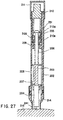
The following description will discuss the relationship between the adjustment
mechanism 210 and the stopper 205 more specifically. The shift range of the stopper
205, etc. from the first position to the second position is indicated by the position of the
adjustment mechanism 210 in the length direction and distance X (see FIG. 26) from
plane A (see FIG. 26) of the stopper-side shift restriction mechanism 51 and plane B
(see FIG. 26) of the adjustment-mechanism-side shift restriction mechanism 210a.
FIG. 37 shows a state in which the shift range from the first position to the second
position is small, and FIG. 38 shows a state in which the shift range from the first
position to the second position is large. Here, the position of the adjustment
mechanism 210 in the length direction is determined by the position of the protruding
member 212b of the connecting section 212 inside the helical groove 210d of the
adjustment mechanism 210, which is given by axially rotating the adjustment
mechanism 210. In other words, distance X is adjusted and determined by axially
rotating the adjustment mechanism 210.
Moreover, the following description will discuss the relationship between the
recess 210e formed in the inner face of the adjustment mechanism 210 and the fixing
protrusion 212c that is placed in the connecting section 212 more specifically. For
example, it is supposed that the difference in positions of the helical groove 210d in the
axial length direction of the adjustment mechanism 210 (the difference between the
state having a large range from the first position to the second position and the state
having a small range from the first position to the second position) is set at 1 mm, and
that five recesses 210e are formed in the inner face of the adjustment mechanism 210
with equal intervals (with 45-degree intervals around the central axis in the length
direction of the sticking tool 201). In this case, distance X can be adjusted by 0.25 mm
for each step. Moreover, if it is supposed that the difference in positions of the helical
groove 210d in the axial length direction of the adjustment mechanism 210 (the
difference between the state having a large range from the first position to the second
position and the state having a small range from the first position to the second
position) is set at 1 mm, and that recesses 210e are formed in the inner face of the
adjustment mechanism 210 at positions with respective angles of 0 degree, 18
degrees, 54 degrees, 108 degrees, and 180 degrees, distance X can be adjusted not
at equal intervals, but at predetermined values such as 0.1 mm, 0.2 mm, 0.3 mm and
0.4 mm.
Here, it is preferable to provide a mark 210f on the uninserted portion 210b so
as to allow visual confirmation of a set value that is to be adjusted by the adjustment
mechanism 210.
The connecting section 212 is preferably provided with one or two or more slits
212a that extend in the length direction. The installation of the slits 212a makes it
possible to accept a distortion that occurs inside the adjustment mechanism 210 when
the stopper-side shift restriction mechanism 251 and the adjustment-mechanism-side
shift restriction mechanism 210a come into contact with each other. With this
arrangement, it is possible to reduce vibration that occurs in the entire structure of the
sticking tool 201 when the stopper-side shift restriction mechanism 251 and the
adjustment-mechanism-side shift restriction mechanism 210a come into contact with
each other. Therefore, it becomes possible to prevent an accidental separation of the
sticking tool 201 from the hand of the operator by the vibration, trembling during the
sticking operation and unnecessary pain being given to the person whose body fluids
are sampled.
Moreover, the adjustment mechanism 210 is connected through the connecting
section 212 so that the connection of the adjustment mechanism 210 is made with a
space 213 between the outer face of the adjustment mechanism 210 from at least the
vicinity of the adjustment-mechanism-side shift restriction mechanism 210a to the tip
end and the inner face of the housing.
The space 213 makes it possible to accept a distortion that occurs outside the
adjustment mechanism 210 when the stopper-side shift restriction mechanism 251 and
the adjustment-mechanism-side shift restriction mechanism 210a come into contact
with each other. With this arrangement, in the same manner as the installation of the
slits 212a in the connecting section 212 as described above, it is possible to reduce
vibration that occurs in the entire structure of the sticking tool 201 when the stopper-side
shift restriction mechanism 251 and the adjustment-mechanism-side shift
restriction mechanism 210a come into contact with each other. Therefore, it becomes
possible to prevent an accidental separation of the sticking tool 201 from the hand of
the operator by the vibration, trembling during the sticking operation and unnecessary
pain being given to the person whose body fluids are sampled. Additionally, an outer
diameter section 210c which is virtually identical to the inner diameter of the housing
202 is preferably attached to the adjustment mechanism 210; thus, it becomes
possible to axially rotate the adjustment mechanism 210 stably even with the space
213.
In the present invention, the connecting section 212 is not necessarily provided,
and another structure may be provided in which a protruding member corresponding to
the protruding member 212b is attached to either one of the inner face of the housing
202 and the outer face of the adjustment mechanism 210 and a helical groove
corresponding to the helical groove 210d is formed in the other so that the position of
the adjustment mechanism 210 is adjusted by axially rotating the adjustment
mechanism.
It is preferable to install a cap 214 on the tip end of the housing 202. This
forms a structure in which the sticking needle 211 is not allowed to protrude outside
the cap when the plunger 203, etc. is located at the first position, thereby making it
possible to prevent the sticking needle 211 from erroneously hurting the hand or the
finger. The installation method of the cap 214 and the housing 202 is not particularly
limited, and a snap-in method and a screwing method by using threads are listed so as
to allow easy removal. Here, an opening 214a is formed in the contact face to the
surface of a living body of the cap 214, and its diameter is set in the range of not less
than 1 mm to not more than 10 mm, and more preferably in the range of not less than
1 mm to not more than 6 mm, so as to carry out the sticking operation without limiting
the portion to be stuck.
Moreover, the cap may have another structure as indicated by a cap 214b
whose cross-sectional view of the tip portion is shown in FIG. 39. The cap 214b
houses a lancet 204b which can slide inside thereof and to which a sticking needle
241 b is connected. The cap 214b makes it possible to connect the other end of the
lancet 204 to the plunger 203 when the cap 214b is connected to the housing 202b;
thus, the same application as described in an explanation of the application of the
present embodiment that will be given later is available.
In the present embodiment, it is preferable to respectively provide an axial
direction groove 222 in the inner face of the housing 202 and a tremble-preventing
protrusion 231 on the plunger 203. The tremble-preventing protrusion 231 shifts along
the axial direction groove 222 so that the plunger 203 is allowed to move only in the
axial direction in a stable manner without trembling in the axial rotation direction;
therefore, this allows the sticking needle 241 to stick at an accurate position.
The materials of the above-mentioned constituent parts are not particularly
limited, and they are appropriately selected from hard plastics, metals, etc. However,
with respect to at least the sliding face of the plunger 203 against the inner face of the
housing 202 or at least the sliding face of the housing 202 against the plunger 203, it is
preferable to use a material, such as a thermoplastic elastomer and rubber, which can
maintain the sliding face in an air-sealed state. By providing the air-sealed state, after
having pressed the tip end of the housing 202 onto the surface of a living body and
stuck the surface of the living body with the sticking needle 241, when the plunger 203
is returned from the second position to the first position, a space inside the housing
202, formed by the plunger 203 and the tip end sealed by the surface of a living body,
is brought to a reduced-pressure state so that the surface of the living body is sucked
and body fluids to be sampled are effectively sucked. Moreover, a suction means may
be preliminarily provided so that the space inside the housing 202, formed by the
plunger 203 and the tip end sealed by the surface of a living body, is brought to a
reduced-pressure state, thereby making the surface of the living body swell into the
housing 202. Then, the swelled surface may be stuck with the sticking needle 241 so
as to effectively suck body fluids to be sampled.
In the case when the suction process is carried out after the sticking operation
on the surface of a living body, upon movement of the plunger 203 to the second
position, the space inside the housing 202, formed by the plunger 203 and the tip end
sealed by the surface of a living body, tends to have a positive pressure, making the
sticking process inoperable. For this reason, it is preferable to install a one-directional
valve, such as a duck bill valve, in either the housing 202, the plunger 203, or the cap
214, so as to release the air inside the housing 202 causing the positive pressure out
of the housing 202, or so as not to allow the outer air to flow into the housing 202
having a reduced pressure.
Next, an explanation will be given of the application of the present embodiment.
First, the operator removes the protection cover 211, and sets the second position of
the plunger 203, the lancet 204 and the stopper 205 which allows to suck a minimum
amount of body fluids such as blood required for an inspection, that is, the shift
distance of the sticking needle 241. Thus, it becomes possible to reduce a pain
accompanying the sticking operation to a minimum level required. Once the
adjustment mechanism 210 has been set, it is not necessary to frequently reset the
setting; therefore, the use of the protection cover 11 makes it possible to prevent the
sticking needle from being stuck deeper due to an erroneous change in the depth of
sticking, erroneous blood sampling, and other misoperations.
Next, the lancet 204 having the sticking needle 241 is attached to the tip end of
the plunger 203, and the plunger 203 with the lancet 204 attached thereto is pushed
toward the rear end against the elastic force of the sticking-use spring 206 so that the
stopping section 207 is engaged by the edge of the engaging section 208. At this
time, the sticking-use spring 206 is maintained in a compressed state. Thus,
preparation for the sticking operation onto the surface of a living body is completed
(see FIG. 26).
Then, the opening 214a of the tip end of the cap 214 is pressed onto the
surface of a living body such as the finger tip, and the stopping section 207 protruding
from the engaging section 208 is pressed. This releases the engagement between the
stopping section 207 and the engaging section 208, and the sticking-use spring 206,
which has been compressed, extends with its elastic force so that the plunger 203 is
shifted toward the tip end, the sticking needle 241 protrudes from the opening 214a of
the cap 214, and carries out a sticking operation onto the surface 215 of a living body
(see FIG. 27). At this time, the stopper 205 slides inside the housing 202 together with
the plunger 203, the stopper-side shift restriction mechanism 251 of the stopper 205
comes into contact with the adjustment-mechanism-side shift restriction mechanism
210a of the adjustment mechanism 210 so that the shift of the plunger 203 toward the
tip end is restricted; thus, the depth of sticking by the sticking needle 241 of the lancet
204 onto the surface of a living body is adjusted to a predetermined depth. After the
sticking operation of the sticking needle 241 onto the surface of the living body, the
sticking-use spring 208 returns to its natural length through damping movements, and
the sticking needle is drawn from the surface of the living body and stored in the
housing 202 (see FIG. 28).
As described above, the sticking tool 201 is designed so that the lancet 204
does not protrude from the opening 214a of the tip end of the cap 214 except that it is
used for the sticking operation; therefore, it is possible to prevent the sticking needle
from erroneously hurt the skin, etc., to prevent contagion, etc., and also to provide a
highly safe device. With the stopper 205 and the adjustment mechanism, the sticking
operation can be performed onto the predetermined sticking position with high
reproducibility.
The sticking tool of the present invention is provided with the mechanism for
adjusting the depth of sticking by the lancet; this allows the operator to set the depth of
sticking suitable for obtaining a minimum amount of blood required for an inspection,
and makes it possible to reduce a pain accompanying the sticking operation to a
minimum level required.