EP1621143A2 - Surgical instrument incorporating an electrically actuated pivoting articulation mechanism - Google Patents
Surgical instrument incorporating an electrically actuated pivoting articulation mechanism Download PDFInfo
- Publication number
- EP1621143A2 EP1621143A2 EP05254694A EP05254694A EP1621143A2 EP 1621143 A2 EP1621143 A2 EP 1621143A2 EP 05254694 A EP05254694 A EP 05254694A EP 05254694 A EP05254694 A EP 05254694A EP 1621143 A2 EP1621143 A2 EP 1621143A2
- Authority
- EP
- European Patent Office
- Prior art keywords
- surgical instrument
- attached
- eap
- articulation
- frame
- Prior art date
- Legal status (The legal status is an assumption and is not a legal conclusion. Google has not performed a legal analysis and makes no representation as to the accuracy of the status listed.)
- Granted
Links
- 230000007246 mechanism Effects 0.000 title claims abstract description 40
- 239000000835 fiber Substances 0.000 claims abstract description 46
- 239000012636 effector Substances 0.000 claims abstract description 34
- 229920001746 electroactive polymer Polymers 0.000 claims description 137
- 238000010304 firing Methods 0.000 claims description 34
- 230000033001 locomotion Effects 0.000 claims description 21
- 230000004044 response Effects 0.000 claims description 3
- 238000012546 transfer Methods 0.000 claims description 3
- 229920000642 polymer Polymers 0.000 abstract description 7
- 210000001519 tissue Anatomy 0.000 description 16
- 230000000694 effects Effects 0.000 description 10
- 239000010410 layer Substances 0.000 description 9
- 239000012530 fluid Substances 0.000 description 7
- 230000008901 benefit Effects 0.000 description 4
- 210000000988 bone and bone Anatomy 0.000 description 4
- 230000008859 change Effects 0.000 description 4
- 239000002131 composite material Substances 0.000 description 4
- 230000008602 contraction Effects 0.000 description 4
- BASFCYQUMIYNBI-UHFFFAOYSA-N platinum Chemical compound [Pt] BASFCYQUMIYNBI-UHFFFAOYSA-N 0.000 description 4
- 238000003780 insertion Methods 0.000 description 3
- 230000037431 insertion Effects 0.000 description 3
- 239000000463 material Substances 0.000 description 3
- 229920005594 polymer fiber Polymers 0.000 description 3
- 238000013459 approach Methods 0.000 description 2
- 230000006835 compression Effects 0.000 description 2
- 238000007906 compression Methods 0.000 description 2
- 229920001940 conductive polymer Polymers 0.000 description 2
- 238000011161 development Methods 0.000 description 2
- 239000003814 drug Substances 0.000 description 2
- 229940079593 drug Drugs 0.000 description 2
- 238000002651 drug therapy Methods 0.000 description 2
- 238000001415 gene therapy Methods 0.000 description 2
- 210000000056 organ Anatomy 0.000 description 2
- 229910052697 platinum Inorganic materials 0.000 description 2
- 238000002360 preparation method Methods 0.000 description 2
- 238000013519 translation Methods 0.000 description 2
- 230000014616 translation Effects 0.000 description 2
- 238000002604 ultrasonography Methods 0.000 description 2
- 230000009471 action Effects 0.000 description 1
- 230000003213 activating effect Effects 0.000 description 1
- 239000012790 adhesive layer Substances 0.000 description 1
- 230000004888 barrier function Effects 0.000 description 1
- 230000009286 beneficial effect Effects 0.000 description 1
- 230000015572 biosynthetic process Effects 0.000 description 1
- 238000006243 chemical reaction Methods 0.000 description 1
- 230000008878 coupling Effects 0.000 description 1
- 238000010168 coupling process Methods 0.000 description 1
- 238000005859 coupling reaction Methods 0.000 description 1
- 230000007812 deficiency Effects 0.000 description 1
- 230000000881 depressing effect Effects 0.000 description 1
- 238000013461 design Methods 0.000 description 1
- 238000005516 engineering process Methods 0.000 description 1
- 238000010438 heat treatment Methods 0.000 description 1
- 150000002500 ions Chemical class 0.000 description 1
- 238000012986 modification Methods 0.000 description 1
- 230000004048 modification Effects 0.000 description 1
- 210000003205 muscle Anatomy 0.000 description 1
- 230000002980 postoperative effect Effects 0.000 description 1
- 238000011084 recovery Methods 0.000 description 1
- 230000000284 resting effect Effects 0.000 description 1
- 239000004753 textile Substances 0.000 description 1
- 230000001225 therapeutic effect Effects 0.000 description 1
- 239000010409 thin film Substances 0.000 description 1
Images


Classifications
-
- A—HUMAN NECESSITIES
- A61—MEDICAL OR VETERINARY SCIENCE; HYGIENE
- A61B—DIAGNOSIS; SURGERY; IDENTIFICATION
- A61B17/00—Surgical instruments, devices or methods, e.g. tourniquets
- A61B17/068—Surgical staplers, e.g. containing multiple staples or clamps
- A61B17/072—Surgical staplers, e.g. containing multiple staples or clamps for applying a row of staples in a single action, e.g. the staples being applied simultaneously
- A61B17/07207—Surgical staplers, e.g. containing multiple staples or clamps for applying a row of staples in a single action, e.g. the staples being applied simultaneously the staples being applied sequentially
-
- A—HUMAN NECESSITIES
- A61—MEDICAL OR VETERINARY SCIENCE; HYGIENE
- A61B—DIAGNOSIS; SURGERY; IDENTIFICATION
- A61B17/00—Surgical instruments, devices or methods, e.g. tourniquets
- A61B17/068—Surgical staplers, e.g. containing multiple staples or clamps
- A61B17/072—Surgical staplers, e.g. containing multiple staples or clamps for applying a row of staples in a single action, e.g. the staples being applied simultaneously
-
- A—HUMAN NECESSITIES
- A61—MEDICAL OR VETERINARY SCIENCE; HYGIENE
- A61B—DIAGNOSIS; SURGERY; IDENTIFICATION
- A61B17/00—Surgical instruments, devices or methods, e.g. tourniquets
-
- A—HUMAN NECESSITIES
- A61—MEDICAL OR VETERINARY SCIENCE; HYGIENE
- A61B—DIAGNOSIS; SURGERY; IDENTIFICATION
- A61B17/00—Surgical instruments, devices or methods, e.g. tourniquets
- A61B17/068—Surgical staplers, e.g. containing multiple staples or clamps
-
- A—HUMAN NECESSITIES
- A61—MEDICAL OR VETERINARY SCIENCE; HYGIENE
- A61B—DIAGNOSIS; SURGERY; IDENTIFICATION
- A61B17/00—Surgical instruments, devices or methods, e.g. tourniquets
- A61B2017/00017—Electrical control of surgical instruments
-
- A—HUMAN NECESSITIES
- A61—MEDICAL OR VETERINARY SCIENCE; HYGIENE
- A61B—DIAGNOSIS; SURGERY; IDENTIFICATION
- A61B17/00—Surgical instruments, devices or methods, e.g. tourniquets
- A61B2017/00367—Details of actuation of instruments, e.g. relations between pushing buttons, or the like, and activation of the tool, working tip, or the like
- A61B2017/00398—Details of actuation of instruments, e.g. relations between pushing buttons, or the like, and activation of the tool, working tip, or the like using powered actuators, e.g. stepper motors, solenoids
-
- A—HUMAN NECESSITIES
- A61—MEDICAL OR VETERINARY SCIENCE; HYGIENE
- A61B—DIAGNOSIS; SURGERY; IDENTIFICATION
- A61B17/00—Surgical instruments, devices or methods, e.g. tourniquets
- A61B2017/00831—Material properties
- A61B2017/00867—Material properties shape memory effect
- A61B2017/00871—Material properties shape memory effect polymeric
-
- A—HUMAN NECESSITIES
- A61—MEDICAL OR VETERINARY SCIENCE; HYGIENE
- A61B—DIAGNOSIS; SURGERY; IDENTIFICATION
- A61B17/00—Surgical instruments, devices or methods, e.g. tourniquets
- A61B17/28—Surgical forceps
- A61B17/29—Forceps for use in minimally invasive surgery
- A61B2017/2926—Details of heads or jaws
- A61B2017/2927—Details of heads or jaws the angular position of the head being adjustable with respect to the shaft
Definitions
- the present invention relates in general to surgical instruments that are suitable for endoscopically inserting an end effector (e.g., endocutter, grasper, cutter, staplers, clip applier, access device, drug/gene therapy delivery device, and an energy device using ultrasound, RF, laser, etc.) to a surgical site, and more particularly to such surgical instruments with an articulating shaft.
- an end effector e.g., endocutter, grasper, cutter, staplers, clip applier, access device, drug/gene therapy delivery device, and an energy device using ultrasound, RF, laser, etc.
- Endoscopic surgical instruments are often preferred over traditional open surgical devices since a smaller incision tends to reduce the post-operative recovery time and complications. Consequently, significant development has gone into a range of endoscopic surgical instruments that are suitable for precise placement of a distal end effector at a desired surgical site through a cannula of a trocar. These distal end effectors engage the tissue in a number of ways to achieve a diagnostic or therapeutic effect (e.g., endocutter, grasper, cutter, staplers, clip applier, access device, drug/gene therapy delivery device, and energy device using ultrasound, RF, laser, etc.).
- a diagnostic or therapeutic effect e.g., endocutter, grasper, cutter, staplers, clip applier, access device, drug/gene therapy delivery device, and energy device using ultrasound, RF, laser, etc.
- Positioning the end effector is constrained by the trocar.
- these endoscopic surgical instruments include a long shaft between the end effector and a handle portion manipulated by the clinician. This long shaft enables insertion to a desired depth and rotation about the longitudinal axis of the shaft, thereby positioning the end effector to a degree. With judicious placement of the trocar and use of graspers, for instance, through another trocar, often this amount of positioning is sufficient.
- Surgical stapling and severing instruments such as described in U.S. Pat. No. 5,465,895, are an example of an endoscopic surgical instrument that successfully positions an end effector by insertion and rotation.
- articulated positioning permits the clinician to more easily engage tissue in some instances, such as behind an organ.
- articulated positioning advantageously allows an endoscope to be positioned behind the end effector without being blocked by the instrument shaft.
- U.S. Pat. No. 5,865,361 that includes an articulation link offset from a camming pivot such that pushing or pulling longitudinal translation of the articulation link effects articulation to a respective side.
- U.S. Pat. No. 5,797,537 discloses a similar rod passing through the shaft to effect articulation.
- the invention overcomes the above-noted and other deficiencies of the prior art by providing a surgical instrument having an articulating shaft attached between a handle and an end effector.
- An electroactive polymer (EAP) actuator disposed in an articulation joint of the shaft is responsive to an electrical signal passed through the shaft to effect articulation.
- a distal portion of the shaft is pinned to a proximal portion of the shaft forming a pivoting articulation joint.
- the EAP actuator is connected between the distal and proximal frame portions to effect articulation.
- a surgical instrument in one aspect of the invention, includes an articulating joint attached between an end effector and a distal end of an elongate shaft.
- An electrical actuator is positioned to actuate the articulation joint in response to an electrical signal remotely produced in a handle proximally attached to the elongate shaft.
- a surgical instrument has an elongate shaft having a frame assembly and an encompassing and a longitudinally, slidingly received closure sleeve assembly.
- a staple applying assembly includes an elongate channel, a staple cartridge engaged in the elongate channel, and an anvil pivotally attached to the elongate channel presenting a staple forming surface to the staple cartridge.
- An articulation joint is formed in the frame assembly.
- a distal frame portion is attached to the elongate channel and a proximal frame portion is pivotally pinned to the distal frame portion.
- a handle attached to a proximal end of the elongate shaft selectively communicates an electrical signal to the elongate shaft to an electroactive polymer actuator connected to the articulation joint that responds thereto to perform articulation of the staple applying assembly.
- a surgical stapling and severing instrument is provided that may approach tissue from a desired angle.
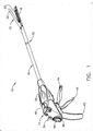
- FIGURE 1 is a rear perspective view of an endoscopic surgical stapling instrument for surgical stapling and severing in an open, unarticulated state.
- FIGURE 2 is a perspective view of a laminate Electroactive Polymer (EAP) composite.
- FIGURE 3 is a perspective view of an EAP plate actuator formed from a stack formed from an adhesively affixed plurality of laminate EAP composites of FIG. 2.
- FIGURE 4 is a perspective view of a cutaway along a longitudinal axis of a contracting EAP fiber actuator.
- FIGURE 5 is a front view in elevation taken in cross section along lines 5-5 of the contracting EAP fiber actuator of FIG. 4.
- FIGURE 6 is a front right perspective view of an EAP actuated articulation joint for the surgical instrument of FIG. 1 with a flex closure sleeve assembly, a pivoting frame assembly and a closed staple applying assembly.
- FIGURE 7 is a front right perspective view of the EAP actuated articulation joint and closed staple applying assembly of FIG. 6 with a flexible closure sleeve assembly removed and a single pivot frame assembly partially exploded.
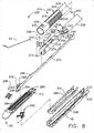
- FIGURE 8 is a front right exploded perspective view of the EAP actuated articulation joint and staple applying assembly of FIG. 6.
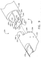
- FIGURE 9 is a detail view of the exploded single pivot frame assembly including EAP fiber actuators of FIG. 7.
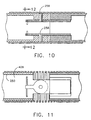
- FIGURE 10 is a right side view in elevation taken in cross section along lines 10-10 of FIG. 6 through a pivot axis of the EAP actuated articulation joint and looking right to see a pair of EAP fiber actuators.
- FIGURE 11 is top view taken in cross section along lines 11-11 of FIG. 11 through a longitudinal axis of the EAP actuated articulation joint looking down to see a lower moment arm and lower EAP fiber actuators.
- FIGURE 12 is a front view in elevation taken in cross section along lines 12-12 of FIG. 10 along the lateral EAP fiber actuators.
- FIGURE 13 is a top view of the EAP actuated articulation joint of FIG. 11 with the right upper and lower EAP fiber actuators contracted to articulate the staple applying assembly to the left.
- FIGURE 14 is front right perspective view of an additional alternative EAP actuated articulation joint that includes a double pivot closure sleeve assembly in a proximal position opening the anvil of the end effector.
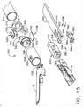
- FIGURE 15 is front right exploded view of the additional alternative EAP actuated articulation joint of FIG. 14 including the double pivot closure sleeve assembly and a single pivot frame assembly.
- FIGURE 16 is right side view in elevation of the alternative EAP actuated articulation joint taken in cross section along lines 16-16 of FIG. 14 with firing components included.
- FIGURE 17 is a top view of the alternative EAP actuated articulation joint in an unarticulated condition taken in cross section along lines 17-17 of FIG. 14.
- FIGURE 18 is a top view of the alternative EAP actuated articulation joint in a leftward articulated condition taken in cross section along lines 17-17 of FIG. 14.
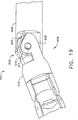
- FIGURE 19 is yet another alternative EAP actuated articulation joint in a slightly articulated condition with a contracting EAP fiber actuator positioned to straighten the joint.
- FIGURE 20 is a right front perspective view of a partially exploded single pivot articulation joint that advantageously includes an EAP articulation locking mechanism that is biased to be normally locked.
- FIGURE 21 is a right front perspective view in detail of a proximal portion of the EAP articulation locking mechanism in a proximal frame ground of the single pivot articulation joint.
- FIGURE 22 is a top view of the single pivot articulation joint of FIG. 20.
- FIGURE 23 is a right side view in elevation of the single pivot articulation joint of FIG. 22 taken in cross section along a longitudinal centerline of lines 23-23.
- FIGURE 24 is a top view of the single pivot articulation joint of FIG. 23 taken in cross section along lines 24-24 to show a gear segment on an upper pivot tang locked by the EAP articulation locking mechanism in an unarticulated condition.
- FIGURE 25 is a top view of the single pivot articulation joint of FIG. 23 taken in cross section along a centerline of lines 24-24 looking down upon a lower pivot tab of a proximal frame ground that is partially articulating an end effector to the left while the EAP articulation locking mechanism is activated to an unlocked condition.
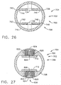
- FIGURE 26 is a front view in elevation of a distal frame ground of the single pivot articulation mechanism of FIG. 24 taken in cross section along lines 26-26 depicting attachment of EAP fiber actuators that articulate the joint.
- FIGURE 27 is a front view in elevation of the proximal frame ground of the single pivot articulation joint of FIG. 24 taken in cross section along lines 27-27 to expose EAP stack actuators and locking pins of the EAP actuated locking mechanisms.
- FIGURE 28 is a top view taken in cross section along an interface between an upper pivot tang of a distal frame ground and an upper pivot tab of a proximal frame ground of a single pivot articulation joint advantageously incorporating lengthened EAP fiber actuators acting upon rounded moment arms in combination with the EAP articulation locking mechanism.
- FIGURE 29 is a front view in elevation taken generally in cross section through the proximal frame ground and EAP articulation locking mechanism but also showing more distally viewed moment arms and lengthened EAP fiber actuators connected thereto.
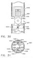
- FIGURE 30 is a top view of a single pivot articulation joint taken in cross section along a top surface of an upper pivot tab of a proximal frame ground to illustrate expansive EAP stack actuators employed against a moment arm distally attached to the upper pivot tab to effect articulation used in conjunction with the normally locked EAP articulation locking mechanism activated in preparation for articulation.
- FIGURE 31 is a front view in elevation of the single pivot articulation joint of FIG. 30 taken in cross section through upper and lower tip pins from the moment arms and through the EAP stack actuators.
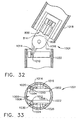
- FIGURE 32 is a top view of the single pivot articulation joint of FIG. 30 taken in cross section along a top surface of the upper pivot tab of the proximal frame ground after articulation of the distal frame ground to the left but before deenergizing the EAP articulation locking mechanism to effect articulation locking.
- FIGURE 33 is a front view in elevation of the single pivot articulation joint of FIG. 31 taken in cross section through the upper and lower tip pins from the moment arms and through the expanded left and compressed right EAP stack actuators.
- a surgical instrument depicted as a surgical severing and stapling instrument 10, has at its distal end an end effector of a staple applying assembly 12, spaced apart from a handle 14 by an elongate shaft 16.
- the staple applying assembly 12 includes a staple channel 18 for receiving a replaceable staple cartridge 20. Pivotally attached to the staple channel 18 is an anvil 22 that clamps tissue against the staple cartridge 20 for stapling and severing.
- the staple applying assembly 12 When the staple applying assembly 12 is closed, its cross sectional area, as well as the elongate shaft 16 are suitable for insertion through a small surgical opening, such as through a cannula of a trocar (not shown).
- a rotation knob 30 causes rotation of the shaft 16 about its longitudinal axis, and hence rotation of the staple applying assembly 12. Additional positioning is enabled at an articulation joint 32 in the shaft 16 that pivots the staple applying assembly 12 in an arc from the longitudinal axis of the shaft 16, thereby allowing placement behind an organ or allowing other instruments such as an endoscope (not shown) to be oriented behind the staple applying assembly 12.
- This articulation is advantageously effected by an articulation control switch 34 on the handle 14 that transmits an electrical signal to the articulation joint 32 to an Electroactive Polymer (EAP) actuator 36, powered by an EAP controller and power supply 38 contained within the handle 14.
- EAP Electroactive Polymer
- a surgeon closes the anvil 22 by drawing a closure trigger 40 proximally toward a pistol grip 42. Once clamped thus, the surgeon may grasp a more distally presented firing trigger 44, drawing it back to effect firing of the staple applying assembly 12, which in some applications is achieved in one single firing stroke and in other applications by multiple firing strokes. Firing accomplishes simultaneously stapling of at least two rows of staples while severing the tissue therebetween.
- Retraction of the firing components may be automatically initiated upon full travel.
- a retraction lever 46 may be drawn aft to effect retraction.
- the staple applying assembly 12 may be unclamped and opened by the surgeon slightly drawing the closure trigger 40 aft toward the pistol grip 42 while depressing a closure release button 48 and then releasing the closure trigger 40, thereby releasing the two stapled ends of severed tissue from the staple applying assembly 12.
- the staple applying assembly 12 accomplishes the functions of clamping onto tissue, driving staples and severing tissue by two distinct motions transferred longitudinally down the shaft 16 over a shaft frame (not shown in FIG. 1 but described below regarding FIG. 7).
- This shaft frame assembly is proximally attached to the handle 14 and coupled for rotation with the rotation knob 30.
- An illustrative multi-stroke handle 14 for the surgical stapling and severing instrument 10 of FIG. 1 is described in greater detail in the co-pending and co-owned U.S. patent applications entitled "SURGICAL STAPLING INSTRUMENT INCORPORATING A MULTISTROKE FIRING POSITION INDICATOR AND RETRACTION MECHANISM" to Jeffrey S. Swayze and Frederick E.
- a multi-stroke handle 14 advantageously supports applications with high firing forces over a long distance
- applications consistent with the present invention may incorporate a single firing stroke, such as described in co-pending and commonly owned U.S. patent application "SURGICAL STAPLING INSTRUMENT HAVING SEPARATE DISTINCT CLOSING AND FIRING SYSTEMS" to Frederick E. Shelton IV, Michael E. Setser, and Brian J. Hemmelgarn, Ser. No. 10/441,632, the disclosure of which is hereby incorporated by reference in its entirety.
- Electroactive polymers are a set of conductive doped polymers that change shape when an electrical voltage is applied.
- the conductive polymer is paired to some form of ionic fluid or gel and electrodes. Flow of the ions from the fluid/gel into or out of the conductive polymer is induced by the voltage potential applied and this flow induces the shape change of the polymer.
- the voltage potential ranges from 1V to 4kV depending on the polymer and ionic fluid used. Some of the EAPs contract when voltage is applied and some expand.
- the EAPs may be paired to mechanical means such as springs or flexible plates to change the effect that is caused when the voltage is applied.
- the two basic types are a fiber bundle and a laminate version.
- the fiber bundle consists of fibers around 30- 50 microns. These fibers may be woven into a bundle much like textiles and are often called EAP yarn because of this. This type of EAP contracts when voltage is applied.
- the electrodes are usually a central wire core and a conductive outer sheath, which also serves to contain the ionic fluid that surrounds the fiber bundles.
- An example of a commercially available fiber EAP material is manufactured by Santa Fe Science and Technology and sold as PANIONTM fiber and is described in U.S. Pat. No. 6,667,825, which is hereby incorporated by reference in its entirety.
- the other type is a laminate structure. It consists of a layer of EAP polymer, a layer of ionic gel and two flexible plates that are attached to either side of the laminate. When a voltage is applied, the square laminate plate expands in one direction and contracts in the perpendicular direction.
- EAP material is available from Artificial Muscle Inc, a division of SRI Laboratories. Plate EAP material is also available from EAMEX of Japan and is referred to as thin film EAP.
- EAPs do not change volume when energized; they merely expand or contract in one direction while doing the opposite in the transverse direction.
- the laminate version may be used in its basic form by containing one side against a rigid structure and using the other much like a piston. It may also be adhered to either side of a flexible plate. When one side of the flexible plate EAP is energized, it expands, flexing the plate in the opposite direction. This allows the plate to be flexed in either direction depending on which side is energized.
- An EAP actuator is usually numerous layers or fibers bundled together to work in cooperation.
- the mechanical configuration of the EAP determines the EAP actuator and its capabilities for motion.
- the EAP may be formed into long stands and wrapped around a single central electrode.
- a flexible exterior outer sleeve will form the other electrode for the actuator as well as contain the ionic fluid necessary for the function of the device. In this configuration when the electrical filed is applied to the electrodes, the strands of EAP shorten.
- This configuration of EAP actuator is called a fiber EAP actuator.
- the laminate configuration may be placed in numerous layers on either side of a flexible plate or merely in layers on itself to increase its capabilities. Typical fiber structures have an effective strain of 2-4% where the typical laminate version achieves 20-30% utilizing much higher voltages.
- a laminate EAP composite 100 is depicted as being formed from a positive plate electrode layer 1302 attached to an EAP layer 104, which in turn is attached to an ionic cell layer 106, which in turn is attached to a negative plate electrode layer 108.
- a plurality of five laminate EAP composites 100 are affixed in a stack by adhesive layers 110 therebetween to form an EAP plate actuator 120. It should be appreciated that opposing EAP actuators 120 may be formed that can selectively bend in either direction.
- a contracting EAP fiber actuator 140 includes a longitudinal platinum cathode wire 142 that passes through an insulative polymer proximal end cap 144 through an elongate cylindrical cavity 146 formed within a plastic cylinder wall 148 that is conductively doped to serve as a positive anode.
- a distal end of the platinum cathode wire 142 is embedded into an insulative polymer distal end cap 150.
- a plurality of contracting polymer fibers 152 are arranged parallel with and surrounding the cathode wire 142 and have their ends embedded in respective end caps 144, 150.
- the plastic cylinder wall 148 is peripherally attached around respective end caps 144, 150 to enclose the cylindrical cavity 146 to seal in ionic fluid or gel 154 that fills the space between contracting polymer fibers 152 and cathode wire 142.
- ionic fluid enters the contracting polymer fibers 152, causing their outer diameter to swell with a corresponding contraction in length, thereby drawing the end caps 144, 150 toward one another.
- a surgical severing and stapling instrument 200 includes an EAP actuated articulation joint 202 that is formed in its elongate shaft 204 proximate to the end effector, which is illustrated by the surgical stapling and severing assembly 12 that advantageously responds to separate closure and firing motions that are transferred longitudinally by the elongate shaft 204.
- the EAP actuated articulation joint 202 advantageously adds the desirable clinical flexibility of articulating to the staple applying assembly 12.
- the EAP actuated articulation joint 202 is more particularly a flexible closure and pivoting frame articulation joint 210, which in FIG. 6 is shown to include a flexible closure sleeve assembly 212 having a proximal closure tube 214 and distal closure ring 216 connected by a flexible closure tube 218.
- a flexible closure sleeve assembly 212 having a proximal closure tube 214 and distal closure ring 216 connected by a flexible closure tube 218.
- Left and right longitudinal rows of vertical slits 220, 222 formed in the flexible closure tube 218 allow flexing to the right or to the left for articulation, yet an uninterrupted top longitudinal band 224 transfers a longitudinal closure motion regardless of the amount of such flexing.
- a top portion of the distal closure ring 216 includes a horseshoe aperture 226 that engages an anvil closure feature 228 of the anvil 22.
- the anvil 22 includes laterally projecting pivot pins 230 at its proximal end that pivotally engage pivot apertures 232 formed near the proximal end of the elongate channel 18 (FIGS. 7-8).
- the slightly more distal anvil closure feature 228 thus imparts a closing motion when the flexible closure sleeve assembly 212 moves distally and imparts an opening motion when moving proximally.
- the flexible closure tube 218 may bend along the length of the left and right longitudinal rows of vertical slits 220, 222, thus accommodating an encompassed single pivot frame assembly 234 of the flexible closure and pivoting frame articulation joint 210 when articulated.
- the single pivot frame assembly 234 includes a proximal frame ground 236 with distally projecting top and bottom pivot tabs 238, 240, each having a respective top and bottom pivot pin hole 242, 244.
- the vertically aligned top pivot pin holes 242, 252 and bottom pivot pin holes 244, 254 are respectively engaged by top and bottom frame pivot pins 256, 258 (FIG.10).
- an implement portion 260 of the surgical instrument 200 formed by the elongate shaft 16 and staple applying assembly 12, further includes a firing bar 270 that longitudinally translates through the proximal frame ground 218, through the flexible closure and pivoting frame articulation joint 210, and through a firing slot 272 in the distal frame ground 250 into the staple applying assembly 12.
- Distal and proximal square apertures 274, 276, formed on top of the distal frame ground 250 define a clip bar 278 therebetween that receives a top arm 280 of a clip spring 282 whose lower, distally extended arm 284 asserts a downward pressure on a raised portion 286 along an upper portion of the firing bar 270 corresponding to the empty/missing cartridge lockout portion of firing travel.
- a distally projecting end of the firing bar 270 is attached to an E-beam 288 that assists in spacing the anvil 22 from the staple cartridge 20, severs tissue, and actuates the staple cartridge 20.
- the staple cartridge 20 includes a molded cartridge body 290 that holds a plurality of staples resting upon staple drivers 292 within respective upwardly open staple apertures 294.
- a wedge sled 296 is driven distally by the E-beam 28 21'8, sliding upon a cartridge tray 298 that holds together the various components of the replaceable staple cartridge 20. The wedge sled 296 upwardly cams the staple drivers 292 to force out the staples into deforming contact with the anvil 22 while a cutting surface 300 of the E-beam 288 severs clamped tissue.
- upper pins 302 of the E-beam 288 engage the anvil 22 during firing while middle pins 304 and a bottom foot 306 engage respective top and bottom surfaces into a longitudinal slot 308 formed in the elongate channel 18, with a corresponding longitudinal opening 310 in the cartridge tray 298 and a rearwardly open vertical slot 312 in the cartridge body 290.
- the firing bar 270 is retracted proximally, retracting as well the E-beam 288, allowing the anvil 22 to be opened to release the two stapled and severed tissue portions (not shown).
- the staple applying assembly 12 is described in greater detail in co-pending and commonly-owned U.S. Patent Application Ser. No. 10/955,042, "ARTICULATING SURGICAL STAPLING INSTRUMENT INCORPORATING A TWO-PIECE E-BEAM FIRING MECHANISM" to Frederick E. Shelton IV, et al., filed 30 September 2004, the disclosure of which is hereby incorporated by reference in its entirety.
- an EAP actuator system 400 advantageously actuates the single pivot frame assembly 234 in response to an electrical articulation signal (not shown) received from the handle 14.
- top left and top right EAP fiber actuators 402, 404 attach horizontally to each lateral side of a top distally projecting moment arm 406 attached to the top pivot tab 238.
- the outer ends of the top left and top right EAP fiber actuators 402, 404 are attached to respective upper left and right lateral attachment points 406, 408 of an inner diameter 410 of the distal frame ground 250.
- bottom left and bottom right EAP fiber actuators 412, 414 attach horizontally to each lateral side of a bottom distally projecting moment arm 416 attached to the top pivot tab 238.
- the outer ends of the bottom left and bottom right EAP fiber actuators 412, 414 are attached to respective lower left and right lateral attachment points 418, 420 of the inner diameter 410 of the distal frame ground 250.
- the attachment points 406, 408, 418, 420 are shown to pass through the distal frame ground 250 in FIG. 12 with the left attachment points 406, 418 visible on the exterior of the distal frame ground 250 in FIG. 9.
- the upper and lower right EAP fiber actuators 404, 414 cause them to contract, drawing the upper and lower moment arms 406, 416 toward the right side of the distal frame ground 250, thereby stretching the upper and lower EAP fiber actuators 402, 412, collapsing the left longitudinal row of vertical slits 220, and expanding the right longitudinal row of vertical slits 222.
- a surgical severing and stapling instrument 500 includes an alternative EAP actuated articulation joint 502 that includes a double pivot closure sleeve assembly 504 (FIG. 14-15) and a single pivot frame assembly 506 (FIG. 15-18).
- the staple applying assembly 12 is depicted with the replaceable staple cartridge 20 removed and the anvil 22 open.
- the double pivot closure sleeve assembly 504 is at its proximal position with its distal pivoting axis aligned with a pivoting axis of the frame assembly 506. It should be appreciated that with the closure sleeve assembly 504 moved distally to close the anvil 22, a proximal pivot axis of the closure sleeve assembly 504 also pivots in order to translate over an articulated frame assembly 506.
- the double pivot closure sleeve assembly 504 includes a proximal closure tube 510 whose distal end is keyed to attach to a proximal closure ring 512 having upper and lower distally projecting tangs 514, 516.
- a distal closure tube 518 which includes a horseshoe aperture 520 to engage the anvil closure feature 228 on the anvil 22, is proximally pinned to a distal closure ring 522 having upper and lower proximally projecting tangs 524, 526.
- An upper double pivot link 528 includes upwardly projecting distal and proximal pivot pins 530, 532 that engage respectively an upper distal pin hole 534 in the upper proximally projecting tang 524 and an upper proximal pin hole 536 in the upper distally projecting tang 514.
- a lower double pivot link 538 includes downwardly projecting distal and proximal pivot pins 540, 542 that engage respectively a lower distal pin hole 544 in the lower proximally projecting tang 526 and a lower proximal pin hole 546 in the lower distally projecting tang 516.
- the single pivot frame assembly 506 includes a proximal frame ground 550 whose distal end includes a pivot pin hole 552 centered and proximal to a distally open pivot recess 554 defined between left and right moment arms 556, 558.
- a dog bone link 560 includes a proximal pin 562 that upwardly engages the pivot pin hole 552 in the proximal frame ground 550 and a center bar 564 that pivots between the left and right moment arms 556, 558.
- a distal pin 566 of the dog bone link 560 is rigidly attached into a lower proximal bore 568 in a distal frame ground 570 having distal lateral guides 572 that engage proximal guides 574 in the elongate channel 18.
- An EAP actuation system 580 includes left and right EAP stack actuators 582, 584 that selectively expand to assert an articulation force on the center bar 564 of the dog bone link 560, which passively compresses the other EAP stack actuator.
- the right EAP stack actuator 582 has expanded, pivoting the dog bone link 560 and thus the staple applying assembly 12 to the left and passively compressing the left EAP stack actuator 584.
- yet another alternative EAP actuated articulation joint 600 for a surgical instrument 602 includes a single pivoting frame assembly 604 wherein a proximal frame ground 606 is engaged to a distally projecting tang 608 from a distal frame ground 610 at a pivot pin 612.
- the distally projecting tang 608 is recessed on a right lateral side to define a half teardrop shaped pulley 614 on the right side of the pivot pin 612.
- Attached to a distal point of the half teardrop shaped pulley 614 is a distal end of a contracting EAP fiber actuator 616 that follows the contour thereof and passes into the proximal frame ground 606.
- the contracting EAP fiber actuator 616 may be sufficiently long so that for even a small percentage contraction in a length a significant rotation may be achieved. It should be appreciated that a counter rotating mechanism may be incorporated on a left side of the depicted tang 608 on a similar but reversed mechanism formed on the other side of the EAP articulation joint 600. Articulation Locking Mechanism For Pivoting Articulation Mechanism.
- an EAP actuated articulation lock 700 is incorporated into a pivoting articulation joint 702 for a surgical instrument 704.
- a single pivoting frame assembly 706 is depicted with a proximal frame ground 708 having distally extended upper and lower pivot tabs 710, 712 that are pivotally engaged to proximally directed upper and lower tangs 714, 716 of a distal frame ground 718 that is attached to an end effector 720.
- An upper inner hole 722 in the upper pivot tab 710 is aligned under an upper outer hole 724 in the upper tang 714, which are pivotally pinned together by upper pivot pin 726.
- a lower inner hole 728 in the lower pivot tab 712 is aligned above a lower outer hole 730 in the lower tang 716, which are pivotally pinned together by a lower pivot pin 732.
- Upper and lower moment arms 734, 736 extend distally respectfully from the upper and lower pivot tabs 710, 712.
- the upper moment arm 734 may be urged to the left toward an upper left attachment point 738 formed in the distal frame ground 718 by a generally horizontal upper left EAP fiber actuator 740.
- the upper moment arm 734 may be urged to the right toward an upper right attachment point 742 formed in the distal frame ground 718 by a generally horizontal upper right EAP fiber actuator 744.
- the lower moment arm 736 may be urged to the left toward a lower left attachment point 746 formed in the distal frame ground 718 by a generally horizontal lower left EAP fiber actuator 748.
- the lower moment arm 736 may be urged to the right toward a lower right attachment point 750 formed in the distal frame ground 718 by a generally horizontal lower right EAP fiber actuator 752.
- Closure of the anvil 22 may occur by action of a closure mechanism that is not shown, such as an EAP actuator that acts upon the anvil pivot.
- a firing motion may first close the anvil prior to further motion effecting stapling and severing.
- a closure sleeve assembly or other longitudinally coupled mechanism may impart a closing motion to the anvil 22.
- An upper EAP actuated articulation locking mechanism 800 advantageously unlocks the pivoting articulation joint 702 to allow articulating movement.
- the EAP actuated articulation locking mechanism 800 then relaxes to a locked state, providing a stable locked position that does not require power dissipation, and thus component heating, between changes in an amount of articulation.
- An upper locking bolt assembly 802 is shown in a rectangular upper lock recess 804 formed in the proximal frame ground 708 proximal to and vertically farther from the longitudinal centerline than the upper pivoting tab 710.
- a locking bolt 806 extends a locking tip 808 out of a distal slot 810 formed in the upper lock recess 804 into engagement in a nearest tooth root 812 of a gear segment 814 formed about a proximal surface about the upper pivot tang 714 of the distal frame ground 718.
- the locking bolt 806 proximally terminates in a cross plate 816 that slides longitudinally in the rectangular upper lock recess 804 between the urging of a proximally positioned compression spring 818 and upper left and right EAP stack actuator 820, 822 that may be activated to expand longitudinally, compressing the compression spring 818 as the lock bolt 806 is moved proximally, thereby disengaging the locking tip 808 from the gear segment 814, allow the pivoting articulation joint 702 to be repositioned.
- An upper lock cover 824 closes the upper lock recess 804.
- a lower EAP actuated articulation locking mechanism 830 is identical to the upper locking mechanism 800 but acting on the opposite site against lower pivot tang 716. It should further be appreciated that a similar locking mechanism may be incorporated into a distal portion of an elongate shaft rather than a proximal end. Further, a double pivoting coupling may include a lock at each pivot.
- an unarticulated end effector 720 and pivoting articulation joint 702 (FIGS. 20-24) is inserted into a surgical site.
- EAP locking mechanisms 800, 830 typically deenergized, the locking tip 808 attached to the proximal frame ground 708 engages the gear segment 814 of the distal frame ground 718, locking the single pivot frame assembly 706.
- EAP stack actuators 820, 820 are energized to longitudinally lengthen, unlocking the EAP articulation locking mechanisms 800, 830.
- the articulation joint 702 may be articulated, such as by contracting upper and lower right EAP fiber actuators 744, 752 to pivot the end effector 720 to the left (FIG. 25), presenting a different tooth root 812 to the locking tip 808 so that when deenergized the EAP articulation locking mechanism 800 will lock to the articulation condition of the surgical instrument 704.
- FIGS. 28-29 an alternative EAP articulation system 900 for a single pivot articulation joint 901 is depicted for use in conjunction with the EAP articulation locking mechanism 800 previously described.
- Upper and lower pairs of left and right EAP fiber actuators 902, 904, 906, 908 are lengthened by incorporating upper and lower rounded moment arms 910, 912 distally respectively on upper and lower pivot tabs 914, 916 of a proximal frame ground 918.
- An upper left attachment point 920 in a distal frame ground 922 is slightly higher than an upper right attachment point 924 and a lower left attachment point 926 is also slightly higher than a lower right attachment point 928, corresponding to the upper and lower left EAP fiber actuators 902, 906 wrapping respectively around a higher portion of the corresponding upper and lower rounded moment arms 910, 912 than the upper and lower right EAP fiber actuators 904, 908 (FIG. 29).
- the lengthened EAP fiber actuators 902-908 in combination with the length and contour of the moment arms 910, 912 may be selected as a desirable performance characteristic.
- FIGS. 30-33 an additional alternative EAP articulation system 1000 for a single pivot articulation joint 1001 is depicted for use in conjunction with the EAP articulation locking mechanism 800 previously described.
- EAP fiber actuators that effect articulation
- upper and lower pairs of left and right EAP stack actuators 1002, 1004, 1006, 1008 respectively oppose and laterally move upper and lower longitudinal tracks 1010, 1012.
- a distally projecting upper moment arm 1014 attaches to an upper pivot tab 1016 of a proximal frame ground 1018.
- the EAP articulation locking mechanism 800 is activated to disengage the locking tip 808 from the gear segment 814 in preparation for articulation.
- the upper and lower left EAP stack actuators 1002, 1006 have been energized to expand, laterally moving rightward the upper and lower longitudinal tracks 1010, 1012, thereby compressing the upper and lower EAP stack actuators 1004, 1008 and moving distal frame ground 1022 correspondingly against the reaction force from the upper and lower inwardly directed tip pins 1020, 1030, which in the illustrative articulation is to the left.
Abstract
Description
- This application claims the benefit of U.S. provisional application Ser. No. 60/591,694, entitled "SURGICAL INSTRUMENT INCORPORATING AN ELECTRICALLY ACTUATED ARTICULATION MECHANISM" to Shelton IV, filed 28 July 2004.
- The present invention relates in general to surgical instruments that are suitable for endoscopically inserting an end effector (e.g., endocutter, grasper, cutter, staplers, clip applier, access device, drug/gene therapy delivery device, and an energy device using ultrasound, RF, laser, etc.) to a surgical site, and more particularly to such surgical instruments with an articulating shaft.
- Endoscopic surgical instruments are often preferred over traditional open surgical devices since a smaller incision tends to reduce the post-operative recovery time and complications. Consequently, significant development has gone into a range of endoscopic surgical instruments that are suitable for precise placement of a distal end effector at a desired surgical site through a cannula of a trocar. These distal end effectors engage the tissue in a number of ways to achieve a diagnostic or therapeutic effect (e.g., endocutter, grasper, cutter, staplers, clip applier, access device, drug/gene therapy delivery device, and energy device using ultrasound, RF, laser, etc.).
- Positioning the end effector is constrained by the trocar. Generally these endoscopic surgical instruments include a long shaft between the end effector and a handle portion manipulated by the clinician. This long shaft enables insertion to a desired depth and rotation about the longitudinal axis of the shaft, thereby positioning the end effector to a degree. With judicious placement of the trocar and use of graspers, for instance, through another trocar, often this amount of positioning is sufficient. Surgical stapling and severing instruments, such as described in U.S. Pat. No. 5,465,895, are an example of an endoscopic surgical instrument that successfully positions an end effector by insertion and rotation.
- More recently, U.S. Pat. Serial No. 10/443,617, "SURGICAL STAPLING INSTRUMENT INCORPORATING AN E-BEAM FIRING MECHANISM" to Shelton et al., filed on 20 May 2003, which is hereby incorporated by reference in its entirety, describes an improved "E-beam" firing bar for severing tissue and actuating staples. Some of the additional advantages include affirmatively spacing the jaws of the end effector, or more specifically a staple applying assembly, even if slightly too much or too little tissue is clamped for optimal staple formation. Moreover, the E-beam firing bar engages the end effector and staple cartridge in a way that enables several beneficial lockouts to be incorporated.
- Depending upon the nature of the operation, it may be desirable to further adjust the positioning of the end effector of an endoscopic surgical instrument. In particular, it is often desirable to orient the end effector at an axis transverse to the longitudinal axis of the shaft of the instrument. The transverse movement of the end effector relative to the instrument shaft is conventionally referred to as "articulation". This is typically accomplished by a pivot (or articulation) joint being placed in the extended shaft just proximal to the staple applying assembly. This allows the surgeon to articulate the staple applying assembly remotely to either side for better surgical placement of the staple lines and easier tissue manipulation and orientation. This articulated positioning permits the clinician to more easily engage tissue in some instances, such as behind an organ. In addition, articulated positioning advantageously allows an endoscope to be positioned behind the end effector without being blocked by the instrument shaft.
- Approaches to articulating a surgical stapling and severing instrument tend to be complicated by integrating control of the articulation along with the control of closing the end effector to clamp tissue and fire the end effector (i.e., stapling and severing) within the small diameter constraints of an endoscopic instrument. Generally, the three control motions are all transferred through the shaft as longitudinal translations. For instance, U.S. Pat. No. 5,673,840 discloses an accordion-like articulation mechanism ("flex-neck") that is articulated by selectively drawing back one of two connecting rods through the implement shaft, each rod offset respectively on opposite sides of the shaft centerline. The connecting rods ratchet through a series of discrete positions.
- Another example of longitudinal control of an articulation mechanism is U.S. Pat. No. 5,865,361 that includes an articulation link offset from a camming pivot such that pushing or pulling longitudinal translation of the articulation link effects articulation to a respective side. Similarly, U.S. Pat. No. 5,797,537 discloses a similar rod passing through the shaft to effect articulation.
- In co-pending and commonly owned U.S. Patent Application Ser. No. 10/615,973 "SURGICAL INSTRUMENT INCORPORATING AN ARTICULATION MECHANISM HAVING ROTATION ABOUT THE LONGITUDINAL AXIS" to Frederick E. Shelton IV et al, the disclosure of which is hereby incorporated by reference in its entirety, a rotational motion is used to transfer articulation motion as an alternative to a longitudinal motion.
- While these mechanically communicated articulation motions have successfully enabled an endoscopic surgical stapling and severing instrument to articulate, development trends pose numerous challenges and barriers to entry into the market. Conflicting design objects include a shaft of as small a diameter as possible to reduce the size of the surgical opening yet with sufficient strength to perform the several motions (e.g., closing, firing, articulation, rotation, etc.)
- Consequently, a significant need exists for an articulating surgical instrument that incorporates an articulation mechanism that requires less mechanical mechanisms passing through the shaft of the instrument.
- The invention overcomes the above-noted and other deficiencies of the prior art by providing a surgical instrument having an articulating shaft attached between a handle and an end effector. An electroactive polymer (EAP) actuator disposed in an articulation joint of the shaft is responsive to an electrical signal passed through the shaft to effect articulation. A distal portion of the shaft is pinned to a proximal portion of the shaft forming a pivoting articulation joint. The EAP actuator is connected between the distal and proximal frame portions to effect articulation. Thereby a shaft of an advantageously small diameter may be achieved yet have the functionality of remotely controllable actuation.
- In one aspect of the invention, a surgical instrument includes an articulating joint attached between an end effector and a distal end of an elongate shaft. An electrical actuator is positioned to actuate the articulation joint in response to an electrical signal remotely produced in a handle proximally attached to the elongate shaft.
- In another aspect of the invention, a surgical instrument has an elongate shaft having a frame assembly and an encompassing and a longitudinally, slidingly received closure sleeve assembly. A staple applying assembly includes an elongate channel, a staple cartridge engaged in the elongate channel, and an anvil pivotally attached to the elongate channel presenting a staple forming surface to the staple cartridge. An articulation joint is formed in the frame assembly. In particular, a distal frame portion is attached to the elongate channel and a proximal frame portion is pivotally pinned to the distal frame portion. A handle attached to a proximal end of the elongate shaft selectively communicates an electrical signal to the elongate shaft to an electroactive polymer actuator connected to the articulation joint that responds thereto to perform articulation of the staple applying assembly. Thus, a surgical stapling and severing instrument is provided that may approach tissue from a desired angle.
- These and other objects and advantages of the present invention shall be made apparent from the accompanying drawings and the description thereof.
- The accompanying drawings, which are incorporated in and constitute a part of this specification, illustrate embodiments of the invention, and, together with the general description of the invention given above, and the detailed description of the embodiments given below, serve to explain the principles of the present invention.
- FIGURE 1 is a rear perspective view of an endoscopic surgical stapling instrument for surgical stapling and severing in an open, unarticulated state.
- FIGURE 2 is a perspective view of a laminate Electroactive Polymer (EAP) composite.
- FIGURE 3 is a perspective view of an EAP plate actuator formed from a stack formed from an adhesively affixed plurality of laminate EAP composites of FIG. 2.
- FIGURE 4 is a perspective view of a cutaway along a longitudinal axis of a contracting EAP fiber actuator.
- FIGURE 5 is a front view in elevation taken in cross section along lines 5-5 of the contracting EAP fiber actuator of FIG. 4.
- FIGURE 6 is a front right perspective view of an EAP actuated articulation joint for the surgical instrument of FIG. 1 with a flex closure sleeve assembly, a pivoting frame assembly and a closed staple applying assembly.
- FIGURE 7 is a front right perspective view of the EAP actuated articulation joint and closed staple applying assembly of FIG. 6 with a flexible closure sleeve assembly removed and a single pivot frame assembly partially exploded.
- FIGURE 8 is a front right exploded perspective view of the EAP actuated articulation joint and staple applying assembly of FIG. 6.
- FIGURE 9 is a detail view of the exploded single pivot frame assembly including EAP fiber actuators of FIG. 7.
- FIGURE 10 is a right side view in elevation taken in cross section along lines 10-10 of FIG. 6 through a pivot axis of the EAP actuated articulation joint and looking right to see a pair of EAP fiber actuators.
- FIGURE 11 is top view taken in cross section along lines 11-11 of FIG. 11 through a longitudinal axis of the EAP actuated articulation joint looking down to see a lower moment arm and lower EAP fiber actuators.
- FIGURE 12 is a front view in elevation taken in cross section along lines 12-12 of FIG. 10 along the lateral EAP fiber actuators.
- FIGURE 13 is a top view of the EAP actuated articulation joint of FIG. 11 with the right upper and lower EAP fiber actuators contracted to articulate the staple applying assembly to the left.
- FIGURE 14 is front right perspective view of an additional alternative EAP actuated articulation joint that includes a double pivot closure sleeve assembly in a proximal position opening the anvil of the end effector.
- FIGURE 15 is front right exploded view of the additional alternative EAP actuated articulation joint of FIG. 14 including the double pivot closure sleeve assembly and a single pivot frame assembly.
- FIGURE 16 is right side view in elevation of the alternative EAP actuated articulation joint taken in cross section along lines 16-16 of FIG. 14 with firing components included.
- FIGURE 17 is a top view of the alternative EAP actuated articulation joint in an unarticulated condition taken in cross section along lines 17-17 of FIG. 14.
- FIGURE 18 is a top view of the alternative EAP actuated articulation joint in a leftward articulated condition taken in cross section along lines 17-17 of FIG. 14.
- FIGURE 19 is yet another alternative EAP actuated articulation joint in a slightly articulated condition with a contracting EAP fiber actuator positioned to straighten the joint.
- FIGURE 20 is a right front perspective view of a partially exploded single pivot articulation joint that advantageously includes an EAP articulation locking mechanism that is biased to be normally locked.
- FIGURE 21 is a right front perspective view in detail of a proximal portion of the EAP articulation locking mechanism in a proximal frame ground of the single pivot articulation joint.
- FIGURE 22 is a top view of the single pivot articulation joint of FIG. 20.
- FIGURE 23 is a right side view in elevation of the single pivot articulation joint of FIG. 22 taken in cross section along a longitudinal centerline of lines 23-23.
- FIGURE 24 is a top view of the single pivot articulation joint of FIG. 23 taken in cross section along lines 24-24 to show a gear segment on an upper pivot tang locked by the EAP articulation locking mechanism in an unarticulated condition.
- FIGURE 25 is a top view of the single pivot articulation joint of FIG. 23 taken in cross section along a centerline of lines 24-24 looking down upon a lower pivot tab of a proximal frame ground that is partially articulating an end effector to the left while the EAP articulation locking mechanism is activated to an unlocked condition.
- FIGURE 26 is a front view in elevation of a distal frame ground of the single pivot articulation mechanism of FIG. 24 taken in cross section along lines 26-26 depicting attachment of EAP fiber actuators that articulate the joint.
- FIGURE 27 is a front view in elevation of the proximal frame ground of the single pivot articulation joint of FIG. 24 taken in cross section along lines 27-27 to expose EAP stack actuators and locking pins of the EAP actuated locking mechanisms.
- FIGURE 28 is a top view taken in cross section along an interface between an upper pivot tang of a distal frame ground and an upper pivot tab of a proximal frame ground of a single pivot articulation joint advantageously incorporating lengthened EAP fiber actuators acting upon rounded moment arms in combination with the EAP articulation locking mechanism.
- FIGURE 29 is a front view in elevation taken generally in cross section through the proximal frame ground and EAP articulation locking mechanism but also showing more distally viewed moment arms and lengthened EAP fiber actuators connected thereto.
- FIGURE 30 is a top view of a single pivot articulation joint taken in cross section along a top surface of an upper pivot tab of a proximal frame ground to illustrate expansive EAP stack actuators employed against a moment arm distally attached to the upper pivot tab to effect articulation used in conjunction with the normally locked EAP articulation locking mechanism activated in preparation for articulation.
- FIGURE 31 is a front view in elevation of the single pivot articulation joint of FIG. 30 taken in cross section through upper and lower tip pins from the moment arms and through the EAP stack actuators.
- FIGURE 32 is a top view of the single pivot articulation joint of FIG. 30 taken in cross section along a top surface of the upper pivot tab of the proximal frame ground after articulation of the distal frame ground to the left but before deenergizing the EAP articulation locking mechanism to effect articulation locking.
- FIGURE 33 is a front view in elevation of the single pivot articulation joint of FIG. 31 taken in cross section through the upper and lower tip pins from the moment arms and through the expanded left and compressed right EAP stack actuators.
- In FIG. 1, a surgical instrument, depicted as a surgical severing and stapling
instrument 10, has at its distal end an end effector of astaple applying assembly 12, spaced apart from ahandle 14 by anelongate shaft 16. Thestaple applying assembly 12 includes astaple channel 18 for receiving areplaceable staple cartridge 20. Pivotally attached to thestaple channel 18 is ananvil 22 that clamps tissue against thestaple cartridge 20 for stapling and severing. When thestaple applying assembly 12 is closed, its cross sectional area, as well as theelongate shaft 16 are suitable for insertion through a small surgical opening, such as through a cannula of a trocar (not shown). - Correct placement and orientation of the
staple applying assembly 12 is facilitated by controls on thehandle 14. In particular, arotation knob 30 causes rotation of theshaft 16 about its longitudinal axis, and hence rotation of thestaple applying assembly 12. Additional positioning is enabled at an articulation joint 32 in theshaft 16 that pivots thestaple applying assembly 12 in an arc from the longitudinal axis of theshaft 16, thereby allowing placement behind an organ or allowing other instruments such as an endoscope (not shown) to be oriented behind thestaple applying assembly 12. This articulation is advantageously effected by anarticulation control switch 34 on thehandle 14 that transmits an electrical signal to the articulation joint 32 to an Electroactive Polymer (EAP) actuator 36, powered by an EAP controller andpower supply 38 contained within thehandle 14. - Once positioned with tissue in the
staple applying assembly 12, a surgeon closes theanvil 22 by drawing aclosure trigger 40 proximally toward apistol grip 42. Once clamped thus, the surgeon may grasp a more distally presented firingtrigger 44, drawing it back to effect firing of thestaple applying assembly 12, which in some applications is achieved in one single firing stroke and in other applications by multiple firing strokes. Firing accomplishes simultaneously stapling of at least two rows of staples while severing the tissue therebetween. - Retraction of the firing components may be automatically initiated upon full travel. Alternatively, a
retraction lever 46 may be drawn aft to effect retraction. With the firing components retracted, thestaple applying assembly 12 may be unclamped and opened by the surgeon slightly drawing theclosure trigger 40 aft toward thepistol grip 42 while depressing aclosure release button 48 and then releasing theclosure trigger 40, thereby releasing the two stapled ends of severed tissue from thestaple applying assembly 12. - It should be appreciated that herein spatial terms such as "vertical", "horizontal", etc. are given with reference to the figures, assuming that the longitudinal axis of the
surgical instrument 10 is horizontal with theanvil 22 of thestaple applying assembly 12 aligned vertically on top and thetriggers handle 14. However, in actual practice thesurgical instrument 10 may be oriented at various angles and as such these spatial terms are used relative to thesurgical instrument 10 itself. Further, "proximal" is used to denote a perspective of a clinician who is behind thehandle 14 who places theend effector 12 distal, away from himself. - In FIG. 1, the
staple applying assembly 12 accomplishes the functions of clamping onto tissue, driving staples and severing tissue by two distinct motions transferred longitudinally down theshaft 16 over a shaft frame (not shown in FIG. 1 but described below regarding FIG. 7). This shaft frame assembly is proximally attached to thehandle 14 and coupled for rotation with therotation knob 30. An illustrative multi-stroke handle 14 for the surgical stapling and severinginstrument 10 of FIG. 1 is described in greater detail in the co-pending and co-owned U.S. patent applications entitled "SURGICAL STAPLING INSTRUMENT INCORPORATING A MULTISTROKE FIRING POSITION INDICATOR AND RETRACTION MECHANISM" to Jeffrey S. Swayze and Frederick E. Shelton IV, Ser. No. 10/674,026, and entitled "SURGICAL STAPLING INSTRUMENT INCORPORATING A MULTI-STROKE FIRING MECHANISM WITH AUTOMATIC END OF FIRING TRAVEL RETRACTION", Ser. No. 11/052,632, filed on February 7, 2005 to Kevin Doll, Jeffrey S. Swayze, Frederick E. Shelton IV, and Douglas B. Hoffman, the disclosures of which are hereby incorporated by reference in their entirety, with additional features and variation as described herein. - While a
multi-stroke handle 14 advantageously supports applications with high firing forces over a long distance, applications consistent with the present invention may incorporate a single firing stroke, such as described in co-pending and commonly owned U.S. patent application "SURGICAL STAPLING INSTRUMENT HAVING SEPARATE DISTINCT CLOSING AND FIRING SYSTEMS" to Frederick E. Shelton IV, Michael E. Setser, and Brian J. Hemmelgarn, Ser. No. 10/441,632, the disclosure of which is hereby incorporated by reference in its entirety. - Electroactive polymers (EAPs) are a set of conductive doped polymers that change shape when an electrical voltage is applied. In essence the conductive polymer is paired to some form of ionic fluid or gel and electrodes. Flow of the ions from the fluid/gel into or out of the conductive polymer is induced by the voltage potential applied and this flow induces the shape change of the polymer. The voltage potential ranges from 1V to 4kV depending on the polymer and ionic fluid used. Some of the EAPs contract when voltage is applied and some expand. The EAPs may be paired to mechanical means such as springs or flexible plates to change the effect that is caused when the voltage is applied.
- There are two basic types and multiple configurations of each type. The two basic types are a fiber bundle and a laminate version. The fiber bundle consists of fibers around 30- 50 microns. These fibers may be woven into a bundle much like textiles and are often called EAP yarn because of this. This type of EAP contracts when voltage is applied. The electrodes are usually a central wire core and a conductive outer sheath, which also serves to contain the ionic fluid that surrounds the fiber bundles. An example of a commercially available fiber EAP material is manufactured by Santa Fe Science and Technology and sold as PANION™ fiber and is described in U.S. Pat. No. 6,667,825, which is hereby incorporated by reference in its entirety.
- The other type is a laminate structure. It consists of a layer of EAP polymer, a layer of ionic gel and two flexible plates that are attached to either side of the laminate. When a voltage is applied, the square laminate plate expands in one direction and contracts in the perpendicular direction. Commercially available laminate (plate) EAP material is available from Artificial Muscle Inc, a division of SRI Laboratories. Plate EAP material is also available from EAMEX of Japan and is referred to as thin film EAP.
- It should be noted that EAPs do not change volume when energized; they merely expand or contract in one direction while doing the opposite in the transverse direction. The laminate version may be used in its basic form by containing one side against a rigid structure and using the other much like a piston. It may also be adhered to either side of a flexible plate. When one side of the flexible plate EAP is energized, it expands, flexing the plate in the opposite direction. This allows the plate to be flexed in either direction depending on which side is energized.
- An EAP actuator is usually numerous layers or fibers bundled together to work in cooperation. The mechanical configuration of the EAP determines the EAP actuator and its capabilities for motion. The EAP may be formed into long stands and wrapped around a single central electrode. A flexible exterior outer sleeve will form the other electrode for the actuator as well as contain the ionic fluid necessary for the function of the device. In this configuration when the electrical filed is applied to the electrodes, the strands of EAP shorten. This configuration of EAP actuator is called a fiber EAP actuator. Likewise, the laminate configuration may be placed in numerous layers on either side of a flexible plate or merely in layers on itself to increase its capabilities. Typical fiber structures have an effective strain of 2-4% where the typical laminate version achieves 20-30% utilizing much higher voltages.
- In FIG. 2, a
laminate EAP composite 100 is depicted as being formed from a positive plate electrode layer 1302 attached to anEAP layer 104, which in turn is attached to anionic cell layer 106, which in turn is attached to a negativeplate electrode layer 108. In FIG. 3, a plurality of fivelaminate EAP composites 100 are affixed in a stack byadhesive layers 110 therebetween to form anEAP plate actuator 120. It should be appreciated that opposingEAP actuators 120 may be formed that can selectively bend in either direction. - In FIGS. 4-5, a contracting
EAP fiber actuator 140 includes a longitudinalplatinum cathode wire 142 that passes through an insulative polymerproximal end cap 144 through an elongatecylindrical cavity 146 formed within aplastic cylinder wall 148 that is conductively doped to serve as a positive anode. A distal end of theplatinum cathode wire 142 is embedded into an insulative polymerdistal end cap 150. A plurality ofcontracting polymer fibers 152 are arranged parallel with and surrounding thecathode wire 142 and have their ends embedded inrespective end caps plastic cylinder wall 148 is peripherally attached aroundrespective end caps cylindrical cavity 146 to seal in ionic fluid orgel 154 that fills the space betweencontracting polymer fibers 152 andcathode wire 142. When a voltage is applied across the plastic cylinder wall (anode) 148 andcathode wire 142, ionic fluid enters thecontracting polymer fibers 152, causing their outer diameter to swell with a corresponding contraction in length, thereby drawing the end caps 144, 150 toward one another. EAP Actuated Articulation Joint. - In FIGS. 6-13, a surgical severing and stapling
instrument 200 includes an EAP actuated articulation joint 202 that is formed in itselongate shaft 204 proximate to the end effector, which is illustrated by the surgical stapling and severingassembly 12 that advantageously responds to separate closure and firing motions that are transferred longitudinally by theelongate shaft 204. The EAP actuated articulation joint 202 advantageously adds the desirable clinical flexibility of articulating to thestaple applying assembly 12. - In the illustrative version of FIGS. 6-13, the EAP actuated articulation joint 202 is more particularly a flexible closure and pivoting frame articulation joint 210, which in FIG. 6 is shown to include a flexible
closure sleeve assembly 212 having aproximal closure tube 214 anddistal closure ring 216 connected by aflexible closure tube 218. Left and right longitudinal rows ofvertical slits flexible closure tube 218 allow flexing to the right or to the left for articulation, yet an uninterrupted toplongitudinal band 224 transfers a longitudinal closure motion regardless of the amount of such flexing. It should be appreciated that an identical uninterrupted bottom longitudinal band runs along the bottom of the flexible closure tube 218 (not shown) is opposite to and cooperates with the toplongitudinal band 224 in transferring this motion. In particular, a top portion of thedistal closure ring 216 includes ahorseshoe aperture 226 that engages an anvil closure feature 228 of theanvil 22. In FIG. 7, theanvil 22 includes laterally projecting pivot pins 230 at its proximal end that pivotally engagepivot apertures 232 formed near the proximal end of the elongate channel 18 (FIGS. 7-8). The slightly more distal anvil closure feature 228 thus imparts a closing motion when the flexibleclosure sleeve assembly 212 moves distally and imparts an opening motion when moving proximally. Theflexible closure tube 218 may bend along the length of the left and right longitudinal rows ofvertical slits pivot frame assembly 234 of the flexible closure and pivoting frame articulation joint 210 when articulated. - With particular reference to FIGS. 7-9, the single
pivot frame assembly 234 includes aproximal frame ground 236 with distally projecting top andbottom pivot tabs pivot pin hole distal frame ground 250, eachtang proximal frame ground 236. In particular, the vertically aligned top pivot pin holes 242, 252 and bottom pivot pin holes 244, 254 are respectively engaged by top and bottom frame pivot pins 256, 258 (FIG.10). - In FIG. 8, an implement portion 260 of the
surgical instrument 200, formed by theelongate shaft 16 andstaple applying assembly 12, further includes a firingbar 270 that longitudinally translates through theproximal frame ground 218, through the flexible closure and pivoting frame articulation joint 210, and through afiring slot 272 in thedistal frame ground 250 into thestaple applying assembly 12. Distal and proximalsquare apertures distal frame ground 250, define aclip bar 278 therebetween that receives atop arm 280 of aclip spring 282 whose lower, distally extendedarm 284 asserts a downward pressure on a raisedportion 286 along an upper portion of the firingbar 270 corresponding to the empty/missing cartridge lockout portion of firing travel. - With particular reference to FIG. 8, a distally projecting end of the firing
bar 270 is attached to an E-beam 288 that assists in spacing theanvil 22 from thestaple cartridge 20, severs tissue, and actuates thestaple cartridge 20. Thestaple cartridge 20 includes a moldedcartridge body 290 that holds a plurality of staples resting uponstaple drivers 292 within respective upwardly openstaple apertures 294. Awedge sled 296 is driven distally by the E-beam 28 21'8, sliding upon acartridge tray 298 that holds together the various components of thereplaceable staple cartridge 20. Thewedge sled 296 upwardly cams thestaple drivers 292 to force out the staples into deforming contact with theanvil 22 while a cuttingsurface 300 of theE-beam 288 severs clamped tissue. It should be appreciated thatupper pins 302 of theE-beam 288 engage theanvil 22 during firing whilemiddle pins 304 and abottom foot 306 engage respective top and bottom surfaces into alongitudinal slot 308 formed in theelongate channel 18, with a correspondinglongitudinal opening 310 in thecartridge tray 298 and a rearwardly openvertical slot 312 in thecartridge body 290. Thereafter, the firingbar 270 is retracted proximally, retracting as well theE-beam 288, allowing theanvil 22 to be opened to release the two stapled and severed tissue portions (not shown). - The
staple applying assembly 12 is described in greater detail in co-pending and commonly-owned U.S. Patent Application Ser. No. 10/955,042, "ARTICULATING SURGICAL STAPLING INSTRUMENT INCORPORATING A TWO-PIECE E-BEAM FIRING MECHANISM" to Frederick E. Shelton IV, et al., filed 30 September 2004, the disclosure of which is hereby incorporated by reference in its entirety. - With particular reference to FIGS. 9-13, an
EAP actuator system 400 advantageously actuates the singlepivot frame assembly 234 in response to an electrical articulation signal (not shown) received from thehandle 14. In the illustrative version of FIGS. 7-13, top left and top rightEAP fiber actuators moment arm 406 attached to thetop pivot tab 238. The outer ends of the top left and top rightEAP fiber actuators distal frame ground 250. Similar, bottom left and bottom rightEAP fiber actuators moment arm 416 attached to thetop pivot tab 238. The outer ends of the bottom left and bottom rightEAP fiber actuators distal frame ground 250. The attachment points 406, 408, 418, 420 are shown to pass through thedistal frame ground 250 in FIG. 12 with the left attachment points 406, 418 visible on the exterior of thedistal frame ground 250 in FIG. 9. When activating one pair of EAP actuators, such as in FIG. 13, the upper and lower rightEAP fiber actuators lower moment arms distal frame ground 250, thereby stretching the upper and lowerEAP fiber actuators vertical slits 220, and expanding the right longitudinal row ofvertical slits 222. - In FIGS. 14-18, a surgical severing and stapling instrument 500 includes an alternative EAP actuated articulation joint 502 that includes a double pivot closure sleeve assembly 504 (FIG. 14-15) and a single pivot frame assembly 506 (FIG. 15-18). In FIG. 14, the
staple applying assembly 12 is depicted with thereplaceable staple cartridge 20 removed and theanvil 22 open. Thus, the double pivotclosure sleeve assembly 504 is at its proximal position with its distal pivoting axis aligned with a pivoting axis of theframe assembly 506. It should be appreciated that with theclosure sleeve assembly 504 moved distally to close theanvil 22, a proximal pivot axis of theclosure sleeve assembly 504 also pivots in order to translate over an articulatedframe assembly 506. - With particular reference to FIG. 15, the double pivot
closure sleeve assembly 504 includes aproximal closure tube 510 whose distal end is keyed to attach to aproximal closure ring 512 having upper and lower distally projectingtangs distal closure tube 518, which includes ahorseshoe aperture 520 to engage the anvil closure feature 228 on theanvil 22, is proximally pinned to adistal closure ring 522 having upper and lower proximally projectingtangs double pivot link 528 includes upwardly projecting distal and proximal pivot pins 530, 532 that engage respectively an upperdistal pin hole 534 in the upperproximally projecting tang 524 and an upperproximal pin hole 536 in the upperdistally projecting tang 514. A lowerdouble pivot link 538 includes downwardly projecting distal and proximal pivot pins 540, 542 that engage respectively a lowerdistal pin hole 544 in the lower proximally projectingtang 526 and a lowerproximal pin hole 546 in the lower distally projectingtang 516. - With particular reference to FIGS. 15-18, the single
pivot frame assembly 506 includes aproximal frame ground 550 whose distal end includes apivot pin hole 552 centered and proximal to a distallyopen pivot recess 554 defined between left andright moment arms dog bone link 560 includes aproximal pin 562 that upwardly engages thepivot pin hole 552 in theproximal frame ground 550 and acenter bar 564 that pivots between the left andright moment arms distal pin 566 of thedog bone link 560 is rigidly attached into a lowerproximal bore 568 in adistal frame ground 570 having distal lateral guides 572 that engage proximal guides 574 in theelongate channel 18. - An
EAP actuation system 580 includes left and rightEAP stack actuators center bar 564 of thedog bone link 560, which passively compresses the other EAP stack actuator. In FIG. 18, the rightEAP stack actuator 582 has expanded, pivoting thedog bone link 560 and thus thestaple applying assembly 12 to the left and passively compressing the leftEAP stack actuator 584. - In FIG. 19, yet another alternative EAP actuated articulation joint 600 for a
surgical instrument 602 includes a singlepivoting frame assembly 604 wherein aproximal frame ground 606 is engaged to adistally projecting tang 608 from adistal frame ground 610 at apivot pin 612. Thedistally projecting tang 608 is recessed on a right lateral side to define a half teardrop shapedpulley 614 on the right side of thepivot pin 612. Attached to a distal point of the half teardrop shapedpulley 614 is a distal end of a contractingEAP fiber actuator 616 that follows the contour thereof and passes into theproximal frame ground 606. The contractingEAP fiber actuator 616 may be sufficiently long so that for even a small percentage contraction in a length a significant rotation may be achieved. It should be appreciated that a counter rotating mechanism may be incorporated on a left side of the depictedtang 608 on a similar but reversed mechanism formed on the other side of the EAP articulation joint 600. Articulation Locking Mechanism For Pivoting Articulation Mechanism. - In FIGS. 20-27, an EAP actuated
articulation lock 700 is incorporated into a pivoting articulation joint 702 for asurgical instrument 704. For clarity, a singlepivoting frame assembly 706 is depicted with aproximal frame ground 708 having distally extended upper andlower pivot tabs lower tangs distal frame ground 718 that is attached to anend effector 720. An upperinner hole 722 in theupper pivot tab 710 is aligned under an upperouter hole 724 in theupper tang 714, which are pivotally pinned together byupper pivot pin 726. A lowerinner hole 728 in thelower pivot tab 712 is aligned above a lowerouter hole 730 in thelower tang 716, which are pivotally pinned together by alower pivot pin 732. Upper andlower moment arms lower pivot tabs upper moment arm 734 may be urged to the left toward an upperleft attachment point 738 formed in thedistal frame ground 718 by a generally horizontal upper leftEAP fiber actuator 740. Theupper moment arm 734 may be urged to the right toward an upperright attachment point 742 formed in thedistal frame ground 718 by a generally horizontal upper rightEAP fiber actuator 744. Thelower moment arm 736 may be urged to the left toward a lowerleft attachment point 746 formed in thedistal frame ground 718 by a generally horizontal lower leftEAP fiber actuator 748. Thelower moment arm 736 may be urged to the right toward a lowerright attachment point 750 formed in thedistal frame ground 718 by a generally horizontal lower rightEAP fiber actuator 752. - Closure of the
anvil 22 may occur by action of a closure mechanism that is not shown, such as an EAP actuator that acts upon the anvil pivot. Alternatively, a firing motion may first close the anvil prior to further motion effecting stapling and severing. As a further alternative, a closure sleeve assembly or other longitudinally coupled mechanism (not shown) may impart a closing motion to theanvil 22. - An upper EAP actuated
articulation locking mechanism 800 advantageously unlocks the pivoting articulation joint 702 to allow articulating movement. The EAP actuatedarticulation locking mechanism 800 then relaxes to a locked state, providing a stable locked position that does not require power dissipation, and thus component heating, between changes in an amount of articulation. An upperlocking bolt assembly 802 is shown in a rectangularupper lock recess 804 formed in theproximal frame ground 708 proximal to and vertically farther from the longitudinal centerline than theupper pivoting tab 710. A lockingbolt 806 extends alocking tip 808 out of adistal slot 810 formed in theupper lock recess 804 into engagement in anearest tooth root 812 of agear segment 814 formed about a proximal surface about theupper pivot tang 714 of thedistal frame ground 718. Thelocking bolt 806 proximally terminates in across plate 816 that slides longitudinally in the rectangularupper lock recess 804 between the urging of a proximally positionedcompression spring 818 and upper left and rightEAP stack actuator compression spring 818 as thelock bolt 806 is moved proximally, thereby disengaging thelocking tip 808 from thegear segment 814, allow the pivoting articulation joint 702 to be repositioned. Anupper lock cover 824 closes theupper lock recess 804. - For additional locking support, in FIG. 23, a lower EAP actuated
articulation locking mechanism 830 is identical to theupper locking mechanism 800 but acting on the opposite site againstlower pivot tang 716. It should further be appreciated that a similar locking mechanism may be incorporated into a distal portion of an elongate shaft rather than a proximal end. Further, a double pivoting coupling may include a lock at each pivot. - In use, an
unarticulated end effector 720 and pivoting articulation joint 702 (FIGS. 20-24) is inserted into a surgical site. WithEAP locking mechanisms tip 808 attached to theproximal frame ground 708 engages thegear segment 814 of thedistal frame ground 718, locking the singlepivot frame assembly 706. When desired,EAP stack actuators articulation locking mechanisms EAP fiber actuators end effector 720 to the left (FIG. 25), presenting adifferent tooth root 812 to thelocking tip 808 so that when deenergized the EAParticulation locking mechanism 800 will lock to the articulation condition of thesurgical instrument 704. - In FIGS. 28-29, an alternative
EAP articulation system 900 for a single pivot articulation joint 901 is depicted for use in conjunction with the EAParticulation locking mechanism 800 previously described. Upper and lower pairs of left and rightEAP fiber actuators rounded moment arms lower pivot tabs 914, 916 of aproximal frame ground 918. An upperleft attachment point 920 in adistal frame ground 922 is slightly higher than an upperright attachment point 924 and a lowerleft attachment point 926 is also slightly higher than a lowerright attachment point 928, corresponding to the upper and lower leftEAP fiber actuators 902, 906 wrapping respectively around a higher portion of the corresponding upper and lowerrounded moment arms EAP fiber actuators 904, 908 (FIG. 29). Thereby, the lengthened EAP fiber actuators 902-908 in combination with the length and contour of themoment arms - In FIGS. 30-33, an additional alternative
EAP articulation system 1000 for a single pivot articulation joint 1001 is depicted for use in conjunction with the EAParticulation locking mechanism 800 previously described. Instead of EAP fiber actuators that effect articulation, upper and lower pairs of left and rightEAP stack actuators longitudinal tracks upper moment arm 1014 attaches to anupper pivot tab 1016 of aproximal frame ground 1018. An upper inwardly directedtip pin 1020 at a distal end of theupper moment arm 1014 longitudinally slidingly engages the upperlongitudinal track 1010, and thus responds to the differential contraction and expansion of the upper left and rightEAP stack actuators distal frame ground 1022. A distally projectinglower moment arm 1024 attaches to anupper pivot tab 1026 of theproximal frame ground 1018. A lower inwardly directedtip pin 1030 at a distal end of theupper moment arm 1024 longitudinally slidingly engages the lowerlongitudinal track 1012, and thus responds to the differential contraction and expansion of the lower left and rightEAP stack actuators distal frame ground 1022. - In FIGS. 30-31, the EAP
articulation locking mechanism 800 is activated to disengage thelocking tip 808 from thegear segment 814 in preparation for articulation. In FIGS. 32-33, the upper and lower leftEAP stack actuators longitudinal tracks EAP stack actuators distal frame ground 1022 correspondingly against the reaction force from the upper and lower inwardly directedtip pins - While the present invention has been illustrated by description of several embodiments and while the illustrative embodiments have been described in considerable detail, it is not the intention of the applicant to restrict or in any way limit the scope of the appended claims to such detail. Additional advantages and modifications may readily appear to those skilled in the art.
- What is claimed is:
Claims (13)
- A surgical instrument, comprising:an end effector;an elongate shaft;a pivoting articulation joint including a first frame member attached to a selected one of the end effector and a distal end of the elongate shaft, a second frame member attached to the other one of the end effector and the distal end of the elongate shaft, and a pivoting connection between the first and second frame members; andan electroactive polymer actuator connected between the first and second frame members.
- The surgical instrument of claim 1, wherein the first frame member includes a recess opening toward the pivoting connection and the second frame member, the second frame member including a first moment arm extending into the recess, the electroactive polymer actuator attached between the moment arm and the first frame member across the recess.
- The surgical instrument of claim 2, wherein the electroactive polymer actuator comprises an electroactive polymer fiber actuator operatively configured to contract.
- The surgical instrument of claim 1, wherein the first frame member includes an first upper tang and a lower first tang pivotally attached respectively to an upper second tang and a lower second tang of the second frame member, the upper first and second tangs being laterally spaced from the lower first and second tangs.
- The surgical instrument of claim 4, wherein the first frame member comprises a tube defining a recess that receives the second frame member, at least one of the upper and lower second tangs including a moment arm extending into the recess, the electroactive polymer actuator comprising a pair of opposing electroactive polymer actuators attached to the moment arm and respective lateral interior surfaces of the first frame member.
- The surgical instrument of claim 4, wherein at least one tang includes a circumferentially contoured portion transverse to an axis of articulation of the articulation joint, the electroactive polymer actuator comprising an electroactive polymer fiber actuator attached to and positioned upon the circumferentially contoured portion at one end and attached to the other frame member.
- The surgical instrument of claim 6, wherein at least one tang includes a counter circumferentially contoured portion transverse to the axis of articulation of the articulation joint, the surgical instrument further comprising a counter electroactive polymer fiber actuator attached to and positioned on the counter circumferential portion.
- The surgical instrument of claim 7, wherein a selected one of the upper tangs and a selected one of the lower tangs both include a rounded contour including an upper portion attached to the electroactive polymer fiber and including a lower portion attached to the counter electroactive fiber actuator.
- The surgical instrument of claim 4, wherein the end effector comprises a stapling and severing assembly actuated by a firing bar, the handle portion proximally attached to the firing bar and operably configured to impart longitudinal firing motion to the firing bar, the elongate shaft further comprising a firing bar guide supporting the firing bar through an articulated articulation joint.
- The surgical instrument of claim 9, wherein the end effector further comprises a lower channel operatively configured to receive a staple cartridge and comprises a pivotally attached upper anvil, the handle portion operatively configured to produce a longitudinal closure motion, the elongate shaft further comprising a closure sleeve assembly proximally coupled to the handle portion to transfer the closure motion to a distal connection with the anvil, the closure sleeve assembly operatively configured to pivot about an axis of articulation of the articulation joint in both a retracted position and distally extended position.
- The surgical instrument of claim 1, further comprising an articulation locking mechanism comprising:a longitudinally translating locking member attached to a selected one of the first and second frame member and biased to extend toward and engage the other one of the first and second frame member; andan electroactive polymer actuator operatively configured and positioned to overcome the bias on the longitudinally translating locking member when activated to unlock the articulation joint.
- A surgical instrument, comprising:an elongate shaft comprising a frame assembly encompassed by a longitudinally, slidingly received closure sleeve assembly;a staple applying assembly comprising an elongate channel, a staple cartridge engaged in the elongate channel, and an anvil pivotally attached to the elongate channel presenting a staple forming surface to the staple cartridge;an articulation joint formed in the frame assembly, the frame assembly comprising a distal frame portion attached to the elongate channel and a proximal frame portion pivotally pinned to the distal frame portion;a handle portion attached to a proximal end of the elongate shaft and operatively configured to selectively communicate an electrical signal to the elongate shaft; andan electroactive polymer actuator connected to the articulation joint and responsive to the electrical signal to perform articulation of the staple applying assembly.
- A surgical instrument, comprising:an end effector;an elongate shaft including a distal frame portion attached to the end effector and a proximal frame portion;a pivoting attachment between the distal and proximal frame portions; anda means for actuating the pivoting of the distal frame portion relative to the proximal frame portion about the pivoting attachment in response to an electrical signal.
Applications Claiming Priority (2)
| Application Number | Priority Date | Filing Date | Title |
|---|---|---|---|
| US59169404P | 2004-07-28 | 2004-07-28 | |
| US11/096,096 US7487899B2 (en) | 2004-07-28 | 2005-03-31 | Surgical instrument incorporating EAP complete firing system lockout mechanism |
Publications (3)
| Publication Number | Publication Date |
|---|---|
| EP1621143A2 true EP1621143A2 (en) | 2006-02-01 |
| EP1621143A3 EP1621143A3 (en) | 2006-03-01 |
| EP1621143B1 EP1621143B1 (en) | 2009-01-07 |
Family
ID=35198060
Family Applications (1)
| Application Number | Title | Priority Date | Filing Date |
|---|---|---|---|
| EP05254694A Active EP1621143B1 (en) | 2004-07-28 | 2005-07-27 | Surgical instrument incorporating an electrically actuated pivoting articulation mechanism |
Country Status (6)
| Country | Link |
|---|---|
| EP (1) | EP1621143B1 (en) |
| KR (1) | KR20060092847A (en) |
| AT (1) | ATE419795T1 (en) |
| AU (1) | AU2005203215B2 (en) |
| BR (1) | BRPI0503038A (en) |
| DE (1) | DE602005012188D1 (en) |
Cited By (184)
| Publication number | Priority date | Publication date | Assignee | Title |
|---|---|---|---|---|
| US7862579B2 (en) | 2004-07-28 | 2011-01-04 | Ethicon Endo-Surgery, Inc. | Electroactive polymer-based articulation mechanism for grasper |
| US7914551B2 (en) | 2004-07-28 | 2011-03-29 | Ethicon Endo-Surgery, Inc. | Electroactive polymer-based articulation mechanism for multi-fire surgical fastening instrument |
| US8317074B2 (en) | 2004-07-28 | 2012-11-27 | Ethicon Endo-Surgery, Inc. | Electroactive polymer-based articulation mechanism for circular stapler |
| EP2772204A3 (en) * | 2013-03-01 | 2014-12-03 | Ethicon Endo-Surgery, Inc. | Articulatable surgical instruments with conductive pathways for signal communication |
| US9517068B2 (en) | 2006-01-31 | 2016-12-13 | Ethicon Endo-Surgery, Llc | Surgical instrument with automatically-returned firing member |
| EP2486859A3 (en) * | 2008-02-14 | 2017-01-18 | Ethicon Endo-Surgery, Inc. | Surgical stapling apparatus with control features operable with one hand |
| US9549735B2 (en) | 2013-12-23 | 2017-01-24 | Ethicon Endo-Surgery, Llc | Fastener cartridge comprising a firing member including fastener transfer surfaces |
| US9561032B2 (en) | 2005-08-31 | 2017-02-07 | Ethicon Endo-Surgery, Llc | Staple cartridge comprising a staple driver arrangement |
| US9572574B2 (en) | 2010-09-30 | 2017-02-21 | Ethicon Endo-Surgery, Llc | Tissue thickness compensators comprising therapeutic agents |
| US9574644B2 (en) | 2013-05-30 | 2017-02-21 | Ethicon Endo-Surgery, Llc | Power module for use with a surgical instrument |
| US9585658B2 (en) | 2007-06-04 | 2017-03-07 | Ethicon Endo-Surgery, Llc | Stapling systems |
| US9585657B2 (en) | 2008-02-15 | 2017-03-07 | Ethicon Endo-Surgery, Llc | Actuator for releasing a layer of material from a surgical end effector |
| US9585663B2 (en) | 2004-07-28 | 2017-03-07 | Ethicon Endo-Surgery, Llc | Surgical stapling instrument configured to apply a compressive pressure to tissue |
| US9585660B2 (en) | 2010-01-07 | 2017-03-07 | Ethicon Endo-Surgery, Llc | Method for testing a surgical tool |
| US9592050B2 (en) | 2010-09-30 | 2017-03-14 | Ethicon Endo-Surgery, Llc | End effector comprising a distal tissue abutment member |
| US9592054B2 (en) | 2011-09-23 | 2017-03-14 | Ethicon Endo-Surgery, Llc | Surgical stapler with stationary staple drivers |
| US9592053B2 (en) | 2010-09-30 | 2017-03-14 | Ethicon Endo-Surgery, Llc | Staple cartridge comprising multiple regions |
| US9597075B2 (en) | 2010-07-30 | 2017-03-21 | Ethicon Endo-Surgery, Inc. | Tissue acquisition arrangements and methods for surgical stapling devices |
| US9629623B2 (en) | 2013-03-14 | 2017-04-25 | Ethicon Endo-Surgery, Llc | Drive system lockout arrangements for modular surgical instruments |
| US9629814B2 (en) | 2010-09-30 | 2017-04-25 | Ethicon Endo-Surgery, Llc | Tissue thickness compensator configured to redistribute compressive forces |
| US9629629B2 (en) | 2013-03-14 | 2017-04-25 | Ethicon Endo-Surgey, LLC | Control systems for surgical instruments |
| US9642620B2 (en) | 2013-12-23 | 2017-05-09 | Ethicon Endo-Surgery, Llc | Surgical cutting and stapling instruments with articulatable end effectors |
| US9649110B2 (en) | 2013-04-16 | 2017-05-16 | Ethicon Llc | Surgical instrument comprising a closing drive and a firing drive operated from the same rotatable output |
| US9655624B2 (en) | 2007-01-11 | 2017-05-23 | Ethicon Llc | Surgical stapling device with a curved end effector |
| US9681870B2 (en) | 2013-12-23 | 2017-06-20 | Ethicon Llc | Articulatable surgical instruments with separate and distinct closing and firing systems |
| US9687231B2 (en) | 2008-02-13 | 2017-06-27 | Ethicon Llc | Surgical stapling instrument |
| US9687237B2 (en) | 2011-09-23 | 2017-06-27 | Ethicon Endo-Surgery, Llc | Staple cartridge including collapsible deck arrangement |
| US9687236B2 (en) | 2010-10-01 | 2017-06-27 | Ethicon Endo-Surgery, Inc. | Surgical instrument having a power control circuit |
| US9690362B2 (en) | 2014-03-26 | 2017-06-27 | Ethicon Llc | Surgical instrument control circuit having a safety processor |
| US9693777B2 (en) | 2014-02-24 | 2017-07-04 | Ethicon Llc | Implantable layers comprising a pressed region |
| US9700310B2 (en) | 2013-08-23 | 2017-07-11 | Ethicon Llc | Firing member retraction devices for powered surgical instruments |
| US9706991B2 (en) | 2006-09-29 | 2017-07-18 | Ethicon Endo-Surgery, Inc. | Staple cartridge comprising staples including a lateral base |
| US9724094B2 (en) | 2014-09-05 | 2017-08-08 | Ethicon Llc | Adjunct with integrated sensors to quantify tissue compression |
| US9724098B2 (en) | 2012-03-28 | 2017-08-08 | Ethicon Endo-Surgery, Llc | Staple cartridge comprising an implantable layer |
| US9724092B2 (en) | 2013-12-23 | 2017-08-08 | Ethicon Llc | Modular surgical instruments |
| US9730697B2 (en) | 2012-02-13 | 2017-08-15 | Ethicon Endo-Surgery, Llc | Surgical cutting and fastening instrument with apparatus for determining cartridge and firing motion status |
| US9743929B2 (en) | 2014-03-26 | 2017-08-29 | Ethicon Llc | Modular powered surgical instrument with detachable shaft assemblies |
| US9757123B2 (en) | 2007-01-10 | 2017-09-12 | Ethicon Llc | Powered surgical instrument having a transmission system |
| US9775614B2 (en) | 2011-05-27 | 2017-10-03 | Ethicon Endo-Surgery, Llc | Surgical stapling instruments with rotatable staple deployment arrangements |
| US9795383B2 (en) | 2010-09-30 | 2017-10-24 | Ethicon Llc | Tissue thickness compensator comprising resilient members |
| US9801628B2 (en) | 2014-09-26 | 2017-10-31 | Ethicon Llc | Surgical staple and driver arrangements for staple cartridges |
| US9808246B2 (en) | 2015-03-06 | 2017-11-07 | Ethicon Endo-Surgery, Llc | Method of operating a powered surgical instrument |
| US9814462B2 (en) | 2010-09-30 | 2017-11-14 | Ethicon Llc | Assembly for fastening tissue comprising a compressible layer |
| US9820738B2 (en) | 2014-03-26 | 2017-11-21 | Ethicon Llc | Surgical instrument comprising interactive systems |
| US9826978B2 (en) | 2010-09-30 | 2017-11-28 | Ethicon Llc | End effectors with same side closure and firing motions |
| US9833241B2 (en) | 2014-04-16 | 2017-12-05 | Ethicon Llc | Surgical fastener cartridges with driver stabilizing arrangements |
| US9833242B2 (en) | 2010-09-30 | 2017-12-05 | Ethicon Endo-Surgery, Llc | Tissue thickness compensators |
| US9839428B2 (en) | 2013-12-23 | 2017-12-12 | Ethicon Llc | Surgical cutting and stapling instruments with independent jaw control features |
| US9844376B2 (en) | 2014-11-06 | 2017-12-19 | Ethicon Llc | Staple cartridge comprising a releasable adjunct material |
| US9844374B2 (en) | 2014-12-18 | 2017-12-19 | Ethicon Llc | Surgical instrument systems comprising an articulatable end effector and means for adjusting the firing stroke of a firing member |
| US9844375B2 (en) | 2014-12-18 | 2017-12-19 | Ethicon Llc | Drive arrangements for articulatable surgical instruments |
| US9848873B2 (en) | 2005-08-31 | 2017-12-26 | Ethicon Llc | Fastener cartridge assembly comprising a driver and staple cavity arrangement |
| US9872682B2 (en) | 2007-03-15 | 2018-01-23 | Ethicon Llc | Surgical stapling instrument having a releasable buttress material |
| US9895148B2 (en) | 2015-03-06 | 2018-02-20 | Ethicon Endo-Surgery, Llc | Monitoring speed control and precision incrementing of motor for powered surgical instruments |
| US9895147B2 (en) | 2005-11-09 | 2018-02-20 | Ethicon Llc | End effectors for surgical staplers |
| US9901346B2 (en) | 2008-02-14 | 2018-02-27 | Ethicon Llc | Stapling assembly |
| US9901342B2 (en) | 2015-03-06 | 2018-02-27 | Ethicon Endo-Surgery, Llc | Signal and power communication system positioned on a rotatable shaft |
| US9907620B2 (en) | 2012-06-28 | 2018-03-06 | Ethicon Endo-Surgery, Llc | Surgical end effectors having angled tissue-contacting surfaces |
| US9913648B2 (en) | 2011-05-27 | 2018-03-13 | Ethicon Endo-Surgery, Llc | Surgical system |
| US9913642B2 (en) | 2014-03-26 | 2018-03-13 | Ethicon Llc | Surgical instrument comprising a sensor system |
| US9924961B2 (en) | 2015-03-06 | 2018-03-27 | Ethicon Endo-Surgery, Llc | Interactive feedback system for powered surgical instruments |
| US9924944B2 (en) | 2014-10-16 | 2018-03-27 | Ethicon Llc | Staple cartridge comprising an adjunct material |
| US9931118B2 (en) | 2015-02-27 | 2018-04-03 | Ethicon Endo-Surgery, Llc | Reinforced battery for a surgical instrument |
| US9943309B2 (en) | 2014-12-18 | 2018-04-17 | Ethicon Llc | Surgical instruments with articulatable end effectors and movable firing beam support arrangements |
| US9962158B2 (en) | 2008-02-14 | 2018-05-08 | Ethicon Llc | Surgical stapling apparatuses with lockable end effector positioning systems |
| US9962161B2 (en) | 2014-02-12 | 2018-05-08 | Ethicon Llc | Deliverable surgical instrument |
| US9974538B2 (en) | 2012-03-28 | 2018-05-22 | Ethicon Llc | Staple cartridge comprising a compressible layer |
| US9987000B2 (en) | 2014-12-18 | 2018-06-05 | Ethicon Llc | Surgical instrument assembly comprising a flexible articulation system |
| US9993258B2 (en) | 2015-02-27 | 2018-06-12 | Ethicon Llc | Adaptable surgical instrument handle |
| US9993248B2 (en) | 2015-03-06 | 2018-06-12 | Ethicon Endo-Surgery, Llc | Smart sensors with local signal processing |
| US10004498B2 (en) | 2006-01-31 | 2018-06-26 | Ethicon Llc | Surgical instrument comprising a plurality of articulation joints |
| US10028744B2 (en) | 2015-08-26 | 2018-07-24 | Ethicon Llc | Staple cartridge assembly including staple guides |
| US10039529B2 (en) | 2010-09-17 | 2018-08-07 | Ethicon Llc | Power control arrangements for surgical instruments and batteries |
| US10045781B2 (en) | 2014-06-13 | 2018-08-14 | Ethicon Llc | Closure lockout systems for surgical instruments |
| US10045776B2 (en) | 2015-03-06 | 2018-08-14 | Ethicon Llc | Control techniques and sub-processor contained within modular shaft with select control processing from handle |
| US10045778B2 (en) | 2008-09-23 | 2018-08-14 | Ethicon Llc | Robotically-controlled motorized surgical instrument with an end effector |
| US10052044B2 (en) | 2015-03-06 | 2018-08-21 | Ethicon Llc | Time dependent evaluation of sensor data to determine stability, creep, and viscoelastic elements of measures |
| US10052102B2 (en) | 2015-06-18 | 2018-08-21 | Ethicon Llc | Surgical end effectors with dual cam actuated jaw closing features |
| US10058963B2 (en) | 2006-01-31 | 2018-08-28 | Ethicon Llc | Automated end effector component reloading system for use with a robotic system |
| US10064688B2 (en) | 2006-03-23 | 2018-09-04 | Ethicon Llc | Surgical system with selectively articulatable end effector |
| US10064621B2 (en) | 2012-06-15 | 2018-09-04 | Ethicon Llc | Articulatable surgical instrument comprising a firing drive |
| US10070861B2 (en) | 2006-03-23 | 2018-09-11 | Ethicon Llc | Articulatable surgical device |
| US10070863B2 (en) | 2005-08-31 | 2018-09-11 | Ethicon Llc | Fastener cartridge assembly comprising a fixed anvil |
| US10076325B2 (en) | 2014-10-13 | 2018-09-18 | Ethicon Llc | Surgical stapling apparatus comprising a tissue stop |
| US10076326B2 (en) | 2015-09-23 | 2018-09-18 | Ethicon Llc | Surgical stapler having current mirror-based motor control |
| US10085748B2 (en) | 2014-12-18 | 2018-10-02 | Ethicon Llc | Locking arrangements for detachable shaft assemblies with articulatable surgical end effectors |
| US10085751B2 (en) | 2015-09-23 | 2018-10-02 | Ethicon Llc | Surgical stapler having temperature-based motor control |
| US10105139B2 (en) | 2015-09-23 | 2018-10-23 | Ethicon Llc | Surgical stapler having downstream current-based motor control |
| US10117649B2 (en) | 2014-12-18 | 2018-11-06 | Ethicon Llc | Surgical instrument assembly comprising a lockable articulation system |
| US10117652B2 (en) | 2011-04-29 | 2018-11-06 | Ethicon Llc | End effector comprising a tissue thickness compensator and progressively released attachment members |
| US10149683B2 (en) | 2008-10-10 | 2018-12-11 | Ethicon Llc | Powered surgical cutting and stapling apparatus with manually retractable firing system |
| US10172619B2 (en) | 2015-09-02 | 2019-01-08 | Ethicon Llc | Surgical staple driver arrays |
| US10172620B2 (en) | 2015-09-30 | 2019-01-08 | Ethicon Llc | Compressible adjuncts with bonding nodes |
| US10180463B2 (en) | 2015-02-27 | 2019-01-15 | Ethicon Llc | Surgical apparatus configured to assess whether a performance parameter of the surgical apparatus is within an acceptable performance band |
| US10188393B2 (en) | 2010-09-17 | 2019-01-29 | Ethicon Llc | Surgical instrument battery comprising a plurality of cells |
| US10188385B2 (en) | 2014-12-18 | 2019-01-29 | Ethicon Llc | Surgical instrument system comprising lockable systems |
| US10201363B2 (en) | 2006-01-31 | 2019-02-12 | Ethicon Llc | Motor-driven surgical instrument |
| US10206676B2 (en) | 2008-02-14 | 2019-02-19 | Ethicon Llc | Surgical cutting and fastening instrument |
| US10211586B2 (en) | 2017-06-28 | 2019-02-19 | Ethicon Llc | Surgical shaft assemblies with watertight housings |
| US10213201B2 (en) | 2015-03-31 | 2019-02-26 | Ethicon Llc | Stapling end effector configured to compensate for an uneven gap between a first jaw and a second jaw |
| US10226249B2 (en) | 2013-03-01 | 2019-03-12 | Ethicon Llc | Articulatable surgical instruments with conductive pathways for signal communication |
| US10238386B2 (en) | 2015-09-23 | 2019-03-26 | Ethicon Llc | Surgical stapler having motor control based on an electrical parameter related to a motor current |
| US10245030B2 (en) | 2016-02-09 | 2019-04-02 | Ethicon Llc | Surgical instruments with tensioning arrangements for cable driven articulation systems |
| US10245033B2 (en) | 2015-03-06 | 2019-04-02 | Ethicon Llc | Surgical instrument comprising a lockable battery housing |
| US10258331B2 (en) | 2016-02-12 | 2019-04-16 | Ethicon Llc | Mechanisms for compensating for drivetrain failure in powered surgical instruments |
| US10258418B2 (en) | 2017-06-29 | 2019-04-16 | Ethicon Llc | System for controlling articulation forces |
| US10258333B2 (en) | 2012-06-28 | 2019-04-16 | Ethicon Llc | Surgical fastening apparatus with a rotary end effector drive shaft for selective engagement with a motorized drive system |
| US10258336B2 (en) | 2008-09-19 | 2019-04-16 | Ethicon Llc | Stapling system configured to produce different formed staple heights |
| US10265068B2 (en) | 2015-12-30 | 2019-04-23 | Ethicon Llc | Surgical instruments with separable motors and motor control circuits |
| US10271849B2 (en) | 2015-09-30 | 2019-04-30 | Ethicon Llc | Woven constructs with interlocked standing fibers |
| USD847989S1 (en) | 2016-06-24 | 2019-05-07 | Ethicon Llc | Surgical fastener cartridge |
| US10278780B2 (en) | 2007-01-10 | 2019-05-07 | Ethicon Llc | Surgical instrument for use with robotic system |
| US10292704B2 (en) | 2015-12-30 | 2019-05-21 | Ethicon Llc | Mechanisms for compensating for battery pack failure in powered surgical instruments |
| US10293100B2 (en) | 2004-07-28 | 2019-05-21 | Ethicon Llc | Surgical stapling instrument having a medical substance dispenser |
| US10299878B2 (en) | 2015-09-25 | 2019-05-28 | Ethicon Llc | Implantable adjunct systems for determining adjunct skew |
| US10307170B2 (en) | 2017-06-20 | 2019-06-04 | Ethicon Llc | Method for closed loop control of motor velocity of a surgical stapling and cutting instrument |
| USD850617S1 (en) | 2016-06-24 | 2019-06-04 | Ethicon Llc | Surgical fastener cartridge |
| US10314589B2 (en) | 2006-06-27 | 2019-06-11 | Ethicon Llc | Surgical instrument including a shifting assembly |
| USD851762S1 (en) | 2017-06-28 | 2019-06-18 | Ethicon Llc | Anvil |
| US10327767B2 (en) | 2017-06-20 | 2019-06-25 | Ethicon Llc | Control of motor velocity of a surgical stapling and cutting instrument based on angle of articulation |
| US10327769B2 (en) | 2015-09-23 | 2019-06-25 | Ethicon Llc | Surgical stapler having motor control based on a drive system component |
| US10335145B2 (en) | 2016-04-15 | 2019-07-02 | Ethicon Llc | Modular surgical instrument with configurable operating mode |
| USD854151S1 (en) | 2017-06-28 | 2019-07-16 | Ethicon Llc | Surgical instrument shaft |
| US10357247B2 (en) | 2016-04-15 | 2019-07-23 | Ethicon Llc | Surgical instrument with multiple program responses during a firing motion |
| US10363036B2 (en) | 2015-09-23 | 2019-07-30 | Ethicon Llc | Surgical stapler having force-based motor control |
| US10363031B2 (en) | 2010-09-30 | 2019-07-30 | Ethicon Llc | Tissue thickness compensators for surgical staplers |
| US10363037B2 (en) | 2016-04-18 | 2019-07-30 | Ethicon Llc | Surgical instrument system comprising a magnetic lockout |
| US10368865B2 (en) | 2015-12-30 | 2019-08-06 | Ethicon Llc | Mechanisms for compensating for drivetrain failure in powered surgical instruments |
| US10368864B2 (en) | 2017-06-20 | 2019-08-06 | Ethicon Llc | Systems and methods for controlling displaying motor velocity for a surgical instrument |
| US10376263B2 (en) | 2016-04-01 | 2019-08-13 | Ethicon Llc | Anvil modification members for surgical staplers |
| US10390841B2 (en) | 2017-06-20 | 2019-08-27 | Ethicon Llc | Control of motor velocity of a surgical stapling and cutting instrument based on angle of articulation |
| US10398434B2 (en) | 2017-06-29 | 2019-09-03 | Ethicon Llc | Closed loop velocity control of closure member for robotic surgical instrument |
| US10398433B2 (en) | 2007-03-28 | 2019-09-03 | Ethicon Llc | Laparoscopic clamp load measuring devices |
| US10405859B2 (en) | 2016-04-15 | 2019-09-10 | Ethicon Llc | Surgical instrument with adjustable stop/start control during a firing motion |
| US10413294B2 (en) | 2012-06-28 | 2019-09-17 | Ethicon Llc | Shaft assembly arrangements for surgical instruments |
| US10420550B2 (en) | 2009-02-06 | 2019-09-24 | Ethicon Llc | Motor driven surgical fastener device with switching system configured to prevent firing initiation until activated |
| US10420549B2 (en) | 2008-09-23 | 2019-09-24 | Ethicon Llc | Motorized surgical instrument |
| US10426463B2 (en) | 2006-01-31 | 2019-10-01 | Ehticon LLC | Surgical instrument having a feedback system |
| US10426467B2 (en) | 2016-04-15 | 2019-10-01 | Ethicon Llc | Surgical instrument with detection sensors |
| US10426481B2 (en) | 2014-02-24 | 2019-10-01 | Ethicon Llc | Implantable layer assemblies |
| US10426471B2 (en) | 2016-12-21 | 2019-10-01 | Ethicon Llc | Surgical instrument with multiple failure response modes |
| US10441285B2 (en) | 2012-03-28 | 2019-10-15 | Ethicon Llc | Tissue thickness compensator comprising tissue ingrowth features |
| US10448948B2 (en) | 2016-02-12 | 2019-10-22 | Ethicon Llc | Mechanisms for compensating for drivetrain failure in powered surgical instruments |
| US10448950B2 (en) | 2016-12-21 | 2019-10-22 | Ethicon Llc | Surgical staplers with independently actuatable closing and firing systems |
| US10456137B2 (en) | 2016-04-15 | 2019-10-29 | Ethicon Llc | Staple formation detection mechanisms |
| US10463370B2 (en) | 2008-02-14 | 2019-11-05 | Ethicon Llc | Motorized surgical instrument |
| US10485536B2 (en) | 2010-09-30 | 2019-11-26 | Ethicon Llc | Tissue stapler having an anti-microbial agent |
| US10492785B2 (en) | 2016-12-21 | 2019-12-03 | Ethicon Llc | Shaft assembly comprising a lockout |
| US10499890B2 (en) | 2006-01-31 | 2019-12-10 | Ethicon Llc | Endoscopic surgical instrument with a handle that can articulate with respect to the shaft |
| US10517596B2 (en) | 2016-12-21 | 2019-12-31 | Ethicon Llc | Articulatable surgical instruments with articulation stroke amplification features |
| US10517594B2 (en) | 2014-10-29 | 2019-12-31 | Ethicon Llc | Cartridge assemblies for surgical staplers |
| US10524790B2 (en) | 2011-05-27 | 2020-01-07 | Ethicon Llc | Robotically-controlled surgical stapling devices that produce formed staples having different lengths |
| US10542979B2 (en) | 2016-06-24 | 2020-01-28 | Ethicon Llc | Stamped staples and staple cartridges using the same |
| US10568625B2 (en) | 2016-12-21 | 2020-02-25 | Ethicon Llc | Staple cartridges and arrangements of staples and staple cavities therein |
| US10568652B2 (en) | 2006-09-29 | 2020-02-25 | Ethicon Llc | Surgical staples having attached drivers of different heights and stapling instruments for deploying the same |
| US10575868B2 (en) | 2013-03-01 | 2020-03-03 | Ethicon Llc | Surgical instrument with coupler assembly |
| US10617412B2 (en) | 2015-03-06 | 2020-04-14 | Ethicon Llc | System for detecting the mis-insertion of a staple cartridge into a surgical stapler |
| US10660640B2 (en) | 2008-02-14 | 2020-05-26 | Ethicon Llc | Motorized surgical cutting and fastening instrument |
| US10687806B2 (en) | 2015-03-06 | 2020-06-23 | Ethicon Llc | Adaptive tissue compression techniques to adjust closure rates for multiple tissue types |
| US10695053B2 (en) | 2006-09-29 | 2020-06-30 | Ethicon Llc | Surgical end effectors with staple cartridges |
| US10716614B2 (en) | 2017-06-28 | 2020-07-21 | Ethicon Llc | Surgical shaft assemblies with slip ring assemblies with increased contact pressure |
| US10736628B2 (en) | 2008-09-23 | 2020-08-11 | Ethicon Llc | Motor-driven surgical cutting instrument |
| US10736636B2 (en) | 2014-12-10 | 2020-08-11 | Ethicon Llc | Articulatable surgical instrument system |
| US10758233B2 (en) | 2009-02-05 | 2020-09-01 | Ethicon Llc | Articulatable surgical instrument comprising a firing drive |
| US10765429B2 (en) | 2017-09-29 | 2020-09-08 | Ethicon Llc | Systems and methods for providing alerts according to the operational state of a surgical instrument |
| US10796471B2 (en) | 2017-09-29 | 2020-10-06 | Ethicon Llc | Systems and methods of displaying a knife position for a surgical instrument |
| US10828028B2 (en) | 2016-04-15 | 2020-11-10 | Ethicon Llc | Surgical instrument with multiple program responses during a firing motion |
| US10835249B2 (en) | 2015-08-17 | 2020-11-17 | Ethicon Llc | Implantable layers for a surgical instrument |
| US10842491B2 (en) | 2006-01-31 | 2020-11-24 | Ethicon Llc | Surgical system with an actuation console |
| US10856868B2 (en) | 2016-12-21 | 2020-12-08 | Ethicon Llc | Firing member pin configurations |
| US10881396B2 (en) | 2017-06-20 | 2021-01-05 | Ethicon Llc | Surgical instrument with variable duration trigger arrangement |
| US10945727B2 (en) | 2016-12-21 | 2021-03-16 | Ethicon Llc | Staple cartridge with deformable driver retention features |
| CN112638285A (en) * | 2018-03-23 | 2021-04-09 | 爱惜康有限责任公司 | Surgical instrument with electrical contacts under membrane |
| US10973516B2 (en) | 2016-12-21 | 2021-04-13 | Ethicon Llc | Surgical end effectors and adaptable firing members therefor |
| US10980539B2 (en) | 2015-09-30 | 2021-04-20 | Ethicon Llc | Implantable adjunct comprising bonded layers |
| US11039836B2 (en) | 2007-01-11 | 2021-06-22 | Cilag Gmbh International | Staple cartridge for use with a surgical stapling instrument |
| US11141153B2 (en) | 2014-10-29 | 2021-10-12 | Cilag Gmbh International | Staple cartridges comprising driver arrangements |
| US11179150B2 (en) | 2016-04-15 | 2021-11-23 | Cilag Gmbh International | Systems and methods for controlling a surgical stapling and cutting instrument |
| US11213293B2 (en) | 2016-02-09 | 2022-01-04 | Cilag Gmbh International | Articulatable surgical instruments with single articulation link arrangements |
| US11224426B2 (en) | 2016-02-12 | 2022-01-18 | Cilag Gmbh International | Mechanisms for compensating for drivetrain failure in powered surgical instruments |
| US11272927B2 (en) | 2008-02-15 | 2022-03-15 | Cilag Gmbh International | Layer arrangements for surgical staple cartridges |
| US11517325B2 (en) | 2017-06-20 | 2022-12-06 | Cilag Gmbh International | Closed loop feedback control of motor velocity of a surgical stapling and cutting instrument based on measured displacement distance traveled over a specified time interval |
| US11564686B2 (en) | 2017-06-28 | 2023-01-31 | Cilag Gmbh International | Surgical shaft assemblies with flexible interfaces |
| US11622766B2 (en) | 2012-06-28 | 2023-04-11 | Cilag Gmbh International | Empty clip cartridge lockout |
Families Citing this family (4)
| Publication number | Priority date | Publication date | Assignee | Title |
|---|---|---|---|---|
| US7857183B2 (en) | 2004-07-28 | 2010-12-28 | Ethicon Endo-Surgery, Inc. | Surgical instrument incorporating an electrically actuated articulation mechanism |
| US8905977B2 (en) | 2004-07-28 | 2014-12-09 | Ethicon Endo-Surgery, Inc. | Surgical stapling instrument having an electroactive polymer actuated medical substance dispenser |
| US8057508B2 (en) | 2004-07-28 | 2011-11-15 | Ethicon Endo-Surgery, Inc. | Surgical instrument incorporating an electrically actuated articulation locking mechanism |
| US7784663B2 (en) | 2005-03-17 | 2010-08-31 | Ethicon Endo-Surgery, Inc. | Surgical stapling instrument having load sensing control circuitry |
Citations (5)
| Publication number | Priority date | Publication date | Assignee | Title |
|---|---|---|---|---|
| US5465895A (en) | 1994-02-03 | 1995-11-14 | Ethicon Endo-Surgery, Inc. | Surgical stapler instrument |
| US5673840A (en) | 1994-12-19 | 1997-10-07 | Ethicon Endo-Surgery, Inc. | Surgical instrument |
| US5797537A (en) | 1996-02-20 | 1998-08-25 | Richard-Allan Medical Industries, Inc. | Articulated surgical instrument with improved firing mechanism |
| US5865361A (en) | 1997-09-23 | 1999-02-02 | United States Surgical Corporation | Surgical stapling apparatus |
| US6667825B2 (en) | 2001-01-03 | 2003-12-23 | Santa Fe Science And Technology, Inc. | Stable conjugated polymer electrochromic devices incorporating ionic liquids |
Family Cites Families (2)
| Publication number | Priority date | Publication date | Assignee | Title |
|---|---|---|---|---|
| WO2003013374A1 (en) * | 2001-08-06 | 2003-02-20 | Penn State Research Foundation | Multifunctional tool and method for minimally invasive surgery |
| US6835173B2 (en) * | 2001-10-05 | 2004-12-28 | Scimed Life Systems, Inc. | Robotic endoscope |
-
2005
- 2005-07-22 AU AU2005203215A patent/AU2005203215B2/en not_active Ceased
- 2005-07-27 AT AT05254694T patent/ATE419795T1/en not_active IP Right Cessation
- 2005-07-27 EP EP05254694A patent/EP1621143B1/en active Active
- 2005-07-27 DE DE602005012188T patent/DE602005012188D1/en active Active
- 2005-07-28 BR BRPI0503038-2A patent/BRPI0503038A/en not_active IP Right Cessation
- 2005-07-28 KR KR1020050068922A patent/KR20060092847A/en not_active Application Discontinuation
Patent Citations (5)
| Publication number | Priority date | Publication date | Assignee | Title |
|---|---|---|---|---|
| US5465895A (en) | 1994-02-03 | 1995-11-14 | Ethicon Endo-Surgery, Inc. | Surgical stapler instrument |
| US5673840A (en) | 1994-12-19 | 1997-10-07 | Ethicon Endo-Surgery, Inc. | Surgical instrument |
| US5797537A (en) | 1996-02-20 | 1998-08-25 | Richard-Allan Medical Industries, Inc. | Articulated surgical instrument with improved firing mechanism |
| US5865361A (en) | 1997-09-23 | 1999-02-02 | United States Surgical Corporation | Surgical stapling apparatus |
| US6667825B2 (en) | 2001-01-03 | 2003-12-23 | Santa Fe Science And Technology, Inc. | Stable conjugated polymer electrochromic devices incorporating ionic liquids |
Cited By (438)
| Publication number | Priority date | Publication date | Assignee | Title |
|---|---|---|---|---|
| US10278702B2 (en) | 2004-07-28 | 2019-05-07 | Ethicon Llc | Stapling system comprising a firing bar and a lockout |
| US7914551B2 (en) | 2004-07-28 | 2011-03-29 | Ethicon Endo-Surgery, Inc. | Electroactive polymer-based articulation mechanism for multi-fire surgical fastening instrument |
| US10314590B2 (en) | 2004-07-28 | 2019-06-11 | Ethicon Llc | Articulating surgical stapling instrument incorporating a two-piece e-beam firing mechanism |
| US8317074B2 (en) | 2004-07-28 | 2012-11-27 | Ethicon Endo-Surgery, Inc. | Electroactive polymer-based articulation mechanism for circular stapler |
| US9585663B2 (en) | 2004-07-28 | 2017-03-07 | Ethicon Endo-Surgery, Llc | Surgical stapling instrument configured to apply a compressive pressure to tissue |
| US7862579B2 (en) | 2004-07-28 | 2011-01-04 | Ethicon Endo-Surgery, Inc. | Electroactive polymer-based articulation mechanism for grasper |
| US9737302B2 (en) | 2004-07-28 | 2017-08-22 | Ethicon Llc | Surgical stapling instrument having a restraining member |
| US10485547B2 (en) | 2004-07-28 | 2019-11-26 | Ethicon Llc | Surgical staple cartridges |
| US9737303B2 (en) | 2004-07-28 | 2017-08-22 | Ethicon Llc | Articulating surgical stapling instrument incorporating a two-piece E-beam firing mechanism |
| US10292707B2 (en) | 2004-07-28 | 2019-05-21 | Ethicon Llc | Articulating surgical stapling instrument incorporating a firing mechanism |
| US10293100B2 (en) | 2004-07-28 | 2019-05-21 | Ethicon Llc | Surgical stapling instrument having a medical substance dispenser |
| US10383634B2 (en) | 2004-07-28 | 2019-08-20 | Ethicon Llc | Stapling system incorporating a firing lockout |
| US7879070B2 (en) | 2004-07-28 | 2011-02-01 | Ethicon Endo-Surgery, Inc. | Electroactive polymer-based actuation mechanism for grasper |
| US9844379B2 (en) | 2004-07-28 | 2017-12-19 | Ethicon Llc | Surgical stapling instrument having a clearanced opening |
| US10271846B2 (en) | 2005-08-31 | 2019-04-30 | Ethicon Llc | Staple cartridge for use with a surgical stapler |
| US10245032B2 (en) | 2005-08-31 | 2019-04-02 | Ethicon Llc | Staple cartridges for forming staples having differing formed staple heights |
| US10271845B2 (en) | 2005-08-31 | 2019-04-30 | Ethicon Llc | Fastener cartridge assembly comprising a cam and driver arrangement |
| US10729436B2 (en) | 2005-08-31 | 2020-08-04 | Ethicon Llc | Robotically-controlled surgical stapling devices that produce formed staples having different lengths |
| US10420553B2 (en) | 2005-08-31 | 2019-09-24 | Ethicon Llc | Staple cartridge comprising a staple driver arrangement |
| US10278697B2 (en) | 2005-08-31 | 2019-05-07 | Ethicon Llc | Staple cartridge comprising a staple driver arrangement |
| US9848873B2 (en) | 2005-08-31 | 2017-12-26 | Ethicon Llc | Fastener cartridge assembly comprising a driver and staple cavity arrangement |
| US10842488B2 (en) | 2005-08-31 | 2020-11-24 | Ethicon Llc | Fastener cartridge assembly comprising a fixed anvil and different staple heights |
| US9561032B2 (en) | 2005-08-31 | 2017-02-07 | Ethicon Endo-Surgery, Llc | Staple cartridge comprising a staple driver arrangement |
| US10321909B2 (en) | 2005-08-31 | 2019-06-18 | Ethicon Llc | Staple cartridge comprising a staple including deformable members |
| US10842489B2 (en) | 2005-08-31 | 2020-11-24 | Ethicon Llc | Fastener cartridge assembly comprising a cam and driver arrangement |
| US10159482B2 (en) | 2005-08-31 | 2018-12-25 | Ethicon Llc | Fastener cartridge assembly comprising a fixed anvil and different staple heights |
| US10869664B2 (en) | 2005-08-31 | 2020-12-22 | Ethicon Llc | End effector for use with a surgical stapling instrument |
| US10932774B2 (en) | 2005-08-31 | 2021-03-02 | Ethicon Llc | Surgical end effector for forming staples to different heights |
| US10070863B2 (en) | 2005-08-31 | 2018-09-11 | Ethicon Llc | Fastener cartridge assembly comprising a fixed anvil |
| US10463369B2 (en) | 2005-08-31 | 2019-11-05 | Ethicon Llc | Disposable end effector for use with a surgical instrument |
| US10245035B2 (en) | 2005-08-31 | 2019-04-02 | Ethicon Llc | Stapling assembly configured to produce different formed staple heights |
| US10028742B2 (en) | 2005-11-09 | 2018-07-24 | Ethicon Llc | Staple cartridge comprising staples with different unformed heights |
| US9968356B2 (en) | 2005-11-09 | 2018-05-15 | Ethicon Llc | Surgical instrument drive systems |
| US10149679B2 (en) | 2005-11-09 | 2018-12-11 | Ethicon Llc | Surgical instrument comprising drive systems |
| US9895147B2 (en) | 2005-11-09 | 2018-02-20 | Ethicon Llc | End effectors for surgical staplers |
| US10485539B2 (en) | 2006-01-31 | 2019-11-26 | Ethicon Llc | Surgical instrument with firing lockout |
| US10426463B2 (en) | 2006-01-31 | 2019-10-01 | Ehticon LLC | Surgical instrument having a feedback system |
| US9517068B2 (en) | 2006-01-31 | 2016-12-13 | Ethicon Endo-Surgery, Llc | Surgical instrument with automatically-returned firing member |
| US10463383B2 (en) | 2006-01-31 | 2019-11-05 | Ethicon Llc | Stapling instrument including a sensing system |
| US10058963B2 (en) | 2006-01-31 | 2018-08-28 | Ethicon Llc | Automated end effector component reloading system for use with a robotic system |
| US10299817B2 (en) | 2006-01-31 | 2019-05-28 | Ethicon Llc | Motor-driven fastening assembly |
| US10993717B2 (en) | 2006-01-31 | 2021-05-04 | Ethicon Llc | Surgical stapling system comprising a control system |
| US10004498B2 (en) | 2006-01-31 | 2018-06-26 | Ethicon Llc | Surgical instrument comprising a plurality of articulation joints |
| US10463384B2 (en) | 2006-01-31 | 2019-11-05 | Ethicon Llc | Stapling assembly |
| US10098636B2 (en) | 2006-01-31 | 2018-10-16 | Ethicon Llc | Surgical instrument having force feedback capabilities |
| US10499890B2 (en) | 2006-01-31 | 2019-12-10 | Ethicon Llc | Endoscopic surgical instrument with a handle that can articulate with respect to the shaft |
| US10842491B2 (en) | 2006-01-31 | 2020-11-24 | Ethicon Llc | Surgical system with an actuation console |
| US10278722B2 (en) | 2006-01-31 | 2019-05-07 | Ethicon Llc | Motor-driven surgical cutting and fastening instrument |
| US11051811B2 (en) | 2006-01-31 | 2021-07-06 | Ethicon Llc | End effector for use with a surgical instrument |
| US10893853B2 (en) | 2006-01-31 | 2021-01-19 | Ethicon Llc | Stapling assembly including motor drive systems |
| US10743849B2 (en) | 2006-01-31 | 2020-08-18 | Ethicon Llc | Stapling system including an articulation system |
| US10052099B2 (en) | 2006-01-31 | 2018-08-21 | Ethicon Llc | Surgical instrument system comprising a firing system including a rotatable shaft and first and second actuation ramps |
| US11058420B2 (en) | 2006-01-31 | 2021-07-13 | Cilag Gmbh International | Surgical stapling apparatus comprising a lockout system |
| US10052100B2 (en) | 2006-01-31 | 2018-08-21 | Ethicon Llc | Surgical instrument system configured to detect resistive forces experienced by a tissue cutting implement |
| US10201363B2 (en) | 2006-01-31 | 2019-02-12 | Ethicon Llc | Motor-driven surgical instrument |
| US10653417B2 (en) | 2006-01-31 | 2020-05-19 | Ethicon Llc | Surgical instrument |
| US10070861B2 (en) | 2006-03-23 | 2018-09-11 | Ethicon Llc | Articulatable surgical device |
| US10213262B2 (en) | 2006-03-23 | 2019-02-26 | Ethicon Llc | Manipulatable surgical systems with selectively articulatable fastening device |
| US10064688B2 (en) | 2006-03-23 | 2018-09-04 | Ethicon Llc | Surgical system with selectively articulatable end effector |
| US10420560B2 (en) | 2006-06-27 | 2019-09-24 | Ethicon Llc | Manually driven surgical cutting and fastening instrument |
| US10314589B2 (en) | 2006-06-27 | 2019-06-11 | Ethicon Llc | Surgical instrument including a shifting assembly |
| US10595862B2 (en) | 2006-09-29 | 2020-03-24 | Ethicon Llc | Staple cartridge including a compressible member |
| US10695053B2 (en) | 2006-09-29 | 2020-06-30 | Ethicon Llc | Surgical end effectors with staple cartridges |
| US10172616B2 (en) | 2006-09-29 | 2019-01-08 | Ethicon Llc | Surgical staple cartridge |
| US11406379B2 (en) | 2006-09-29 | 2022-08-09 | Cilag Gmbh International | Surgical end effectors with staple cartridges |
| US10568652B2 (en) | 2006-09-29 | 2020-02-25 | Ethicon Llc | Surgical staples having attached drivers of different heights and stapling instruments for deploying the same |
| US10448952B2 (en) | 2006-09-29 | 2019-10-22 | Ethicon Llc | End effector for use with a surgical fastening instrument |
| US9706991B2 (en) | 2006-09-29 | 2017-07-18 | Ethicon Endo-Surgery, Inc. | Staple cartridge comprising staples including a lateral base |
| US10342541B2 (en) | 2006-10-03 | 2019-07-09 | Ethicon Llc | Surgical instruments with E-beam driver and rotary drive arrangements |
| US10441369B2 (en) | 2007-01-10 | 2019-10-15 | Ethicon Llc | Articulatable surgical instrument configured for detachable use with a robotic system |
| US11064998B2 (en) | 2007-01-10 | 2021-07-20 | Cilag Gmbh International | Surgical instrument with wireless communication between a control unit of a robotic system and remote sensor |
| US10433918B2 (en) | 2007-01-10 | 2019-10-08 | Ethicon Llc | Surgical instrument system configured to evaluate the load applied to a firing member at the initiation of a firing stroke |
| US10517590B2 (en) | 2007-01-10 | 2019-12-31 | Ethicon Llc | Powered surgical instrument having a transmission system |
| US11006951B2 (en) | 2007-01-10 | 2021-05-18 | Ethicon Llc | Surgical instrument with wireless communication between control unit and sensor transponders |
| US9757123B2 (en) | 2007-01-10 | 2017-09-12 | Ethicon Llc | Powered surgical instrument having a transmission system |
| US11000277B2 (en) | 2007-01-10 | 2021-05-11 | Ethicon Llc | Surgical instrument with wireless communication between control unit and remote sensor |
| US10517682B2 (en) | 2007-01-10 | 2019-12-31 | Ethicon Llc | Surgical instrument with wireless communication between control unit and remote sensor |
| US10751138B2 (en) | 2007-01-10 | 2020-08-25 | Ethicon Llc | Surgical instrument for use with a robotic system |
| US10278780B2 (en) | 2007-01-10 | 2019-05-07 | Ethicon Llc | Surgical instrument for use with robotic system |
| US11039836B2 (en) | 2007-01-11 | 2021-06-22 | Cilag Gmbh International | Staple cartridge for use with a surgical stapling instrument |
| US9655624B2 (en) | 2007-01-11 | 2017-05-23 | Ethicon Llc | Surgical stapling device with a curved end effector |
| US9775613B2 (en) | 2007-01-11 | 2017-10-03 | Ethicon Llc | Surgical stapling device with a curved end effector |
| US9999431B2 (en) | 2007-01-11 | 2018-06-19 | Ethicon Endo-Surgery, Llc | Surgical stapling device having supports for a flexible drive mechanism |
| US9750501B2 (en) | 2007-01-11 | 2017-09-05 | Ethicon Endo-Surgery, Llc | Surgical stapling devices having laterally movable anvils |
| US10912575B2 (en) | 2007-01-11 | 2021-02-09 | Ethicon Llc | Surgical stapling device having supports for a flexible drive mechanism |
| US9872682B2 (en) | 2007-03-15 | 2018-01-23 | Ethicon Llc | Surgical stapling instrument having a releasable buttress material |
| US10398433B2 (en) | 2007-03-28 | 2019-09-03 | Ethicon Llc | Laparoscopic clamp load measuring devices |
| US10441280B2 (en) | 2007-06-04 | 2019-10-15 | Ethicon Llc | Robotically-controlled shaft based rotary drive systems for surgical instruments |
| US9795381B2 (en) | 2007-06-04 | 2017-10-24 | Ethicon Endo-Surgery, Llc | Robotically-controlled shaft based rotary drive systems for surgical instruments |
| US10368863B2 (en) | 2007-06-04 | 2019-08-06 | Ethicon Llc | Robotically-controlled shaft based rotary drive systems for surgical instruments |
| US10327765B2 (en) | 2007-06-04 | 2019-06-25 | Ethicon Llc | Drive systems for surgical instruments |
| US10299787B2 (en) | 2007-06-04 | 2019-05-28 | Ethicon Llc | Stapling system comprising rotary inputs |
| US9585658B2 (en) | 2007-06-04 | 2017-03-07 | Ethicon Endo-Surgery, Llc | Stapling systems |
| US9987003B2 (en) | 2007-06-04 | 2018-06-05 | Ethicon Llc | Robotic actuator assembly |
| US9750498B2 (en) | 2007-06-04 | 2017-09-05 | Ethicon Endo Surgery, Llc | Drive systems for surgical instruments |
| US10363033B2 (en) | 2007-06-04 | 2019-07-30 | Ethicon Llc | Robotically-controlled surgical instruments |
| US10765424B2 (en) | 2008-02-13 | 2020-09-08 | Ethicon Llc | Surgical stapling instrument |
| US9687231B2 (en) | 2008-02-13 | 2017-06-27 | Ethicon Llc | Surgical stapling instrument |
| US10660640B2 (en) | 2008-02-14 | 2020-05-26 | Ethicon Llc | Motorized surgical cutting and fastening instrument |
| US9872684B2 (en) | 2008-02-14 | 2018-01-23 | Ethicon Llc | Surgical stapling apparatus including firing force regulation |
| US9901344B2 (en) | 2008-02-14 | 2018-02-27 | Ethicon Llc | Stapling assembly |
| US9901345B2 (en) | 2008-02-14 | 2018-02-27 | Ethicon Llc | Stapling assembly |
| US9901346B2 (en) | 2008-02-14 | 2018-02-27 | Ethicon Llc | Stapling assembly |
| EP2486859A3 (en) * | 2008-02-14 | 2017-01-18 | Ethicon Endo-Surgery, Inc. | Surgical stapling apparatus with control features operable with one hand |
| US10238385B2 (en) | 2008-02-14 | 2019-03-26 | Ethicon Llc | Surgical instrument system for evaluating tissue impedance |
| US9877723B2 (en) | 2008-02-14 | 2018-01-30 | Ethicon Llc | Surgical stapling assembly comprising a selector arrangement |
| US10004505B2 (en) | 2008-02-14 | 2018-06-26 | Ethicon Llc | Detachable motor powered surgical instrument |
| US10206676B2 (en) | 2008-02-14 | 2019-02-19 | Ethicon Llc | Surgical cutting and fastening instrument |
| US10779822B2 (en) | 2008-02-14 | 2020-09-22 | Ethicon Llc | System including a surgical cutting and fastening instrument |
| US9999426B2 (en) | 2008-02-14 | 2018-06-19 | Ethicon Llc | Detachable motor powered surgical instrument |
| US10307163B2 (en) | 2008-02-14 | 2019-06-04 | Ethicon Llc | Detachable motor powered surgical instrument |
| US9962158B2 (en) | 2008-02-14 | 2018-05-08 | Ethicon Llc | Surgical stapling apparatuses with lockable end effector positioning systems |
| US10470763B2 (en) | 2008-02-14 | 2019-11-12 | Ethicon Llc | Surgical cutting and fastening instrument including a sensing system |
| US10463370B2 (en) | 2008-02-14 | 2019-11-05 | Ethicon Llc | Motorized surgical instrument |
| US9867618B2 (en) | 2008-02-14 | 2018-01-16 | Ethicon Llc | Surgical stapling apparatus including firing force regulation |
| US10238387B2 (en) | 2008-02-14 | 2019-03-26 | Ethicon Llc | Surgical instrument comprising a control system |
| US9980729B2 (en) | 2008-02-14 | 2018-05-29 | Ethicon Endo-Surgery, Llc | Detachable motor powered surgical instrument |
| US10265067B2 (en) | 2008-02-14 | 2019-04-23 | Ethicon Llc | Surgical instrument including a regulator and a control system |
| US10390823B2 (en) | 2008-02-15 | 2019-08-27 | Ethicon Llc | End effector comprising an adjunct |
| US11058418B2 (en) | 2008-02-15 | 2021-07-13 | Cilag Gmbh International | Surgical end effector having buttress retention features |
| US10856866B2 (en) | 2008-02-15 | 2020-12-08 | Ethicon Llc | Surgical end effector having buttress retention features |
| US11272927B2 (en) | 2008-02-15 | 2022-03-15 | Cilag Gmbh International | Layer arrangements for surgical staple cartridges |
| US9585657B2 (en) | 2008-02-15 | 2017-03-07 | Ethicon Endo-Surgery, Llc | Actuator for releasing a layer of material from a surgical end effector |
| US10258336B2 (en) | 2008-09-19 | 2019-04-16 | Ethicon Llc | Stapling system configured to produce different formed staple heights |
| US10130361B2 (en) | 2008-09-23 | 2018-11-20 | Ethicon Llc | Robotically-controller motorized surgical tool with an end effector |
| US10105136B2 (en) | 2008-09-23 | 2018-10-23 | Ethicon Llc | Robotically-controlled motorized surgical instrument with an end effector |
| US10420549B2 (en) | 2008-09-23 | 2019-09-24 | Ethicon Llc | Motorized surgical instrument |
| US10045778B2 (en) | 2008-09-23 | 2018-08-14 | Ethicon Llc | Robotically-controlled motorized surgical instrument with an end effector |
| US10898184B2 (en) | 2008-09-23 | 2021-01-26 | Ethicon Llc | Motor-driven surgical cutting instrument |
| US10456133B2 (en) | 2008-09-23 | 2019-10-29 | Ethicon Llc | Motorized surgical instrument |
| US10485537B2 (en) | 2008-09-23 | 2019-11-26 | Ethicon Llc | Motorized surgical instrument |
| US10736628B2 (en) | 2008-09-23 | 2020-08-11 | Ethicon Llc | Motor-driven surgical cutting instrument |
| US11617575B2 (en) | 2008-09-23 | 2023-04-04 | Cilag Gmbh International | Motor-driven surgical cutting instrument |
| US10765425B2 (en) | 2008-09-23 | 2020-09-08 | Ethicon Llc | Robotically-controlled motorized surgical instrument with an end effector |
| US10238389B2 (en) | 2008-09-23 | 2019-03-26 | Ethicon Llc | Robotically-controlled motorized surgical instrument with an end effector |
| US10149683B2 (en) | 2008-10-10 | 2018-12-11 | Ethicon Llc | Powered surgical cutting and stapling apparatus with manually retractable firing system |
| US10758233B2 (en) | 2009-02-05 | 2020-09-01 | Ethicon Llc | Articulatable surgical instrument comprising a firing drive |
| US11129615B2 (en) | 2009-02-05 | 2021-09-28 | Cilag Gmbh International | Surgical stapling system |
| US10420550B2 (en) | 2009-02-06 | 2019-09-24 | Ethicon Llc | Motor driven surgical fastener device with switching system configured to prevent firing initiation until activated |
| US9585660B2 (en) | 2010-01-07 | 2017-03-07 | Ethicon Endo-Surgery, Llc | Method for testing a surgical tool |
| US9597075B2 (en) | 2010-07-30 | 2017-03-21 | Ethicon Endo-Surgery, Inc. | Tissue acquisition arrangements and methods for surgical stapling devices |
| US10470770B2 (en) | 2010-07-30 | 2019-11-12 | Ethicon Llc | Circular surgical fastening devices with tissue acquisition arrangements |
| US10595835B2 (en) | 2010-09-17 | 2020-03-24 | Ethicon Llc | Surgical instrument comprising a removable battery |
| US10188393B2 (en) | 2010-09-17 | 2019-01-29 | Ethicon Llc | Surgical instrument battery comprising a plurality of cells |
| US10039529B2 (en) | 2010-09-17 | 2018-08-07 | Ethicon Llc | Power control arrangements for surgical instruments and batteries |
| US9814462B2 (en) | 2010-09-30 | 2017-11-14 | Ethicon Llc | Assembly for fastening tissue comprising a compressible layer |
| US10398436B2 (en) | 2010-09-30 | 2019-09-03 | Ethicon Llc | Staple cartridge comprising staples positioned within a compressible portion thereof |
| US9833242B2 (en) | 2010-09-30 | 2017-12-05 | Ethicon Endo-Surgery, Llc | Tissue thickness compensators |
| US10265072B2 (en) | 2010-09-30 | 2019-04-23 | Ethicon Llc | Surgical stapling system comprising an end effector including an implantable layer |
| US10064624B2 (en) | 2010-09-30 | 2018-09-04 | Ethicon Llc | End effector with implantable layer |
| US9572574B2 (en) | 2010-09-30 | 2017-02-21 | Ethicon Endo-Surgery, Llc | Tissue thickness compensators comprising therapeutic agents |
| US9833238B2 (en) | 2010-09-30 | 2017-12-05 | Ethicon Endo-Surgery, Llc | Retainer assembly including a tissue thickness compensator |
| US10485536B2 (en) | 2010-09-30 | 2019-11-26 | Ethicon Llc | Tissue stapler having an anti-microbial agent |
| US9826978B2 (en) | 2010-09-30 | 2017-11-28 | Ethicon Llc | End effectors with same side closure and firing motions |
| US10265074B2 (en) | 2010-09-30 | 2019-04-23 | Ethicon Llc | Implantable layers for surgical stapling devices |
| US10258330B2 (en) | 2010-09-30 | 2019-04-16 | Ethicon Llc | End effector including an implantable arrangement |
| US9592050B2 (en) | 2010-09-30 | 2017-03-14 | Ethicon Endo-Surgery, Llc | End effector comprising a distal tissue abutment member |
| US10335150B2 (en) | 2010-09-30 | 2019-07-02 | Ethicon Llc | Staple cartridge comprising an implantable layer |
| US9592053B2 (en) | 2010-09-30 | 2017-03-14 | Ethicon Endo-Surgery, Llc | Staple cartridge comprising multiple regions |
| US10588623B2 (en) | 2010-09-30 | 2020-03-17 | Ethicon Llc | Adhesive film laminate |
| US9833236B2 (en) | 2010-09-30 | 2017-12-05 | Ethicon Llc | Tissue thickness compensator for surgical staplers |
| US9924947B2 (en) | 2010-09-30 | 2018-03-27 | Ethicon Llc | Staple cartridge comprising a compressible portion |
| US9629814B2 (en) | 2010-09-30 | 2017-04-25 | Ethicon Endo-Surgery, Llc | Tissue thickness compensator configured to redistribute compressive forces |
| US10463372B2 (en) | 2010-09-30 | 2019-11-05 | Ethicon Llc | Staple cartridge comprising multiple regions |
| US10335148B2 (en) | 2010-09-30 | 2019-07-02 | Ethicon Llc | Staple cartridge including a tissue thickness compensator for a surgical stapler |
| US10182819B2 (en) | 2010-09-30 | 2019-01-22 | Ethicon Llc | Implantable layer assemblies |
| US10194910B2 (en) | 2010-09-30 | 2019-02-05 | Ethicon Llc | Stapling assemblies comprising a layer |
| US10028743B2 (en) | 2010-09-30 | 2018-07-24 | Ethicon Llc | Staple cartridge assembly comprising an implantable layer |
| US9801634B2 (en) | 2010-09-30 | 2017-10-31 | Ethicon Llc | Tissue thickness compensator for a surgical stapler |
| US9795383B2 (en) | 2010-09-30 | 2017-10-24 | Ethicon Llc | Tissue thickness compensator comprising resilient members |
| US10136890B2 (en) | 2010-09-30 | 2018-11-27 | Ethicon Llc | Staple cartridge comprising a variable thickness compressible portion |
| US10363031B2 (en) | 2010-09-30 | 2019-07-30 | Ethicon Llc | Tissue thickness compensators for surgical staplers |
| US9788834B2 (en) | 2010-09-30 | 2017-10-17 | Ethicon Llc | Layer comprising deployable attachment members |
| US10258332B2 (en) | 2010-09-30 | 2019-04-16 | Ethicon Llc | Stapling system comprising an adjunct and a flowable adhesive |
| US10149682B2 (en) | 2010-09-30 | 2018-12-11 | Ethicon Llc | Stapling system including an actuation system |
| US9687236B2 (en) | 2010-10-01 | 2017-06-27 | Ethicon Endo-Surgery, Inc. | Surgical instrument having a power control circuit |
| US10117652B2 (en) | 2011-04-29 | 2018-11-06 | Ethicon Llc | End effector comprising a tissue thickness compensator and progressively released attachment members |
| US10524790B2 (en) | 2011-05-27 | 2020-01-07 | Ethicon Llc | Robotically-controlled surgical stapling devices that produce formed staples having different lengths |
| US10426478B2 (en) | 2011-05-27 | 2019-10-01 | Ethicon Llc | Surgical stapling systems |
| US10420561B2 (en) | 2011-05-27 | 2019-09-24 | Ethicon Llc | Robotically-driven surgical instrument |
| US9775614B2 (en) | 2011-05-27 | 2017-10-03 | Ethicon Endo-Surgery, Llc | Surgical stapling instruments with rotatable staple deployment arrangements |
| US10004506B2 (en) | 2011-05-27 | 2018-06-26 | Ethicon Llc | Surgical system |
| US9913648B2 (en) | 2011-05-27 | 2018-03-13 | Ethicon Endo-Surgery, Llc | Surgical system |
| US10071452B2 (en) | 2011-05-27 | 2018-09-11 | Ethicon Llc | Automated end effector component reloading system for use with a robotic system |
| US10485546B2 (en) | 2011-05-27 | 2019-11-26 | Ethicon Llc | Robotically-driven surgical assembly |
| US10231794B2 (en) | 2011-05-27 | 2019-03-19 | Ethicon Llc | Surgical stapling instruments with rotatable staple deployment arrangements |
| US10335151B2 (en) | 2011-05-27 | 2019-07-02 | Ethicon Llc | Robotically-driven surgical instrument |
| US10130366B2 (en) | 2011-05-27 | 2018-11-20 | Ethicon Llc | Automated reloading devices for replacing used end effectors on robotic surgical systems |
| US10383633B2 (en) | 2011-05-27 | 2019-08-20 | Ethicon Llc | Robotically-driven surgical assembly |
| US9687237B2 (en) | 2011-09-23 | 2017-06-27 | Ethicon Endo-Surgery, Llc | Staple cartridge including collapsible deck arrangement |
| US9592054B2 (en) | 2011-09-23 | 2017-03-14 | Ethicon Endo-Surgery, Llc | Surgical stapler with stationary staple drivers |
| US9730697B2 (en) | 2012-02-13 | 2017-08-15 | Ethicon Endo-Surgery, Llc | Surgical cutting and fastening instrument with apparatus for determining cartridge and firing motion status |
| US9974538B2 (en) | 2012-03-28 | 2018-05-22 | Ethicon Llc | Staple cartridge comprising a compressible layer |
| US9918716B2 (en) | 2012-03-28 | 2018-03-20 | Ethicon Llc | Staple cartridge comprising implantable layers |
| US10441285B2 (en) | 2012-03-28 | 2019-10-15 | Ethicon Llc | Tissue thickness compensator comprising tissue ingrowth features |
| US9724098B2 (en) | 2012-03-28 | 2017-08-08 | Ethicon Endo-Surgery, Llc | Staple cartridge comprising an implantable layer |
| US10064621B2 (en) | 2012-06-15 | 2018-09-04 | Ethicon Llc | Articulatable surgical instrument comprising a firing drive |
| US10874391B2 (en) | 2012-06-28 | 2020-12-29 | Ethicon Llc | Surgical instrument system including replaceable end effectors |
| US11622766B2 (en) | 2012-06-28 | 2023-04-11 | Cilag Gmbh International | Empty clip cartridge lockout |
| US10639115B2 (en) | 2012-06-28 | 2020-05-05 | Ethicon Llc | Surgical end effectors having angled tissue-contacting surfaces |
| US10383630B2 (en) | 2012-06-28 | 2019-08-20 | Ethicon Llc | Surgical stapling device with rotary driven firing member |
| US10413294B2 (en) | 2012-06-28 | 2019-09-17 | Ethicon Llc | Shaft assembly arrangements for surgical instruments |
| US10420555B2 (en) | 2012-06-28 | 2019-09-24 | Ethicon Llc | Hand held rotary powered surgical instruments with end effectors that are articulatable about multiple axes |
| US10258333B2 (en) | 2012-06-28 | 2019-04-16 | Ethicon Llc | Surgical fastening apparatus with a rotary end effector drive shaft for selective engagement with a motorized drive system |
| US10485541B2 (en) | 2012-06-28 | 2019-11-26 | Ethicon Llc | Robotically powered surgical device with manually-actuatable reversing system |
| US10687812B2 (en) | 2012-06-28 | 2020-06-23 | Ethicon Llc | Surgical instrument system including replaceable end effectors |
| US9907620B2 (en) | 2012-06-28 | 2018-03-06 | Ethicon Endo-Surgery, Llc | Surgical end effectors having angled tissue-contacting surfaces |
| US11058423B2 (en) | 2012-06-28 | 2021-07-13 | Cilag Gmbh International | Stapling system including first and second closure systems for use with a surgical robot |
| US10285695B2 (en) | 2013-03-01 | 2019-05-14 | Ethicon Llc | Articulatable surgical instruments with conductive pathways |
| US9554794B2 (en) | 2013-03-01 | 2017-01-31 | Ethicon Endo-Surgery, Llc | Multiple processor motor control for modular surgical instruments |
| WO2014134007A3 (en) * | 2013-03-01 | 2014-12-11 | Ethicon Endo-Surgery, Inc. | Articulatable surgical instruments with conductive pathways for signal communication |
| EP3685759A1 (en) * | 2013-03-01 | 2020-07-29 | Ethicon LLC | Articulatable surgical instruments with conductive pathways for signal communication |
| US10226249B2 (en) | 2013-03-01 | 2019-03-12 | Ethicon Llc | Articulatable surgical instruments with conductive pathways for signal communication |
| EP2772204A3 (en) * | 2013-03-01 | 2014-12-03 | Ethicon Endo-Surgery, Inc. | Articulatable surgical instruments with conductive pathways for signal communication |
| US10575868B2 (en) | 2013-03-01 | 2020-03-03 | Ethicon Llc | Surgical instrument with coupler assembly |
| US9700309B2 (en) | 2013-03-01 | 2017-07-11 | Ethicon Llc | Articulatable surgical instruments with conductive pathways for signal communication |
| US10470762B2 (en) | 2013-03-14 | 2019-11-12 | Ethicon Llc | Multi-function motor for a surgical instrument |
| US9883860B2 (en) | 2013-03-14 | 2018-02-06 | Ethicon Llc | Interchangeable shaft assemblies for use with a surgical instrument |
| US10238391B2 (en) | 2013-03-14 | 2019-03-26 | Ethicon Llc | Drive train control arrangements for modular surgical instruments |
| US9629629B2 (en) | 2013-03-14 | 2017-04-25 | Ethicon Endo-Surgey, LLC | Control systems for surgical instruments |
| US9629623B2 (en) | 2013-03-14 | 2017-04-25 | Ethicon Endo-Surgery, Llc | Drive system lockout arrangements for modular surgical instruments |
| US10136887B2 (en) | 2013-04-16 | 2018-11-27 | Ethicon Llc | Drive system decoupling arrangement for a surgical instrument |
| US10149680B2 (en) | 2013-04-16 | 2018-12-11 | Ethicon Llc | Surgical instrument comprising a gap setting system |
| US9801626B2 (en) | 2013-04-16 | 2017-10-31 | Ethicon Llc | Modular motor driven surgical instruments with alignment features for aligning rotary drive shafts with surgical end effector shafts |
| US9826976B2 (en) | 2013-04-16 | 2017-11-28 | Ethicon Llc | Motor driven surgical instruments with lockable dual drive shafts |
| US9844368B2 (en) | 2013-04-16 | 2017-12-19 | Ethicon Llc | Surgical system comprising first and second drive systems |
| US10405857B2 (en) | 2013-04-16 | 2019-09-10 | Ethicon Llc | Powered linear surgical stapler |
| US9814460B2 (en) | 2013-04-16 | 2017-11-14 | Ethicon Llc | Modular motor driven surgical instruments with status indication arrangements |
| US9867612B2 (en) | 2013-04-16 | 2018-01-16 | Ethicon Llc | Powered surgical stapler |
| US9649110B2 (en) | 2013-04-16 | 2017-05-16 | Ethicon Llc | Surgical instrument comprising a closing drive and a firing drive operated from the same rotatable output |
| US9574644B2 (en) | 2013-05-30 | 2017-02-21 | Ethicon Endo-Surgery, Llc | Power module for use with a surgical instrument |
| US9924942B2 (en) | 2013-08-23 | 2018-03-27 | Ethicon Llc | Motor-powered articulatable surgical instruments |
| US9987006B2 (en) | 2013-08-23 | 2018-06-05 | Ethicon Llc | Shroud retention arrangement for sterilizable surgical instruments |
| US10828032B2 (en) | 2013-08-23 | 2020-11-10 | Ethicon Llc | End effector detection systems for surgical instruments |
| US9700310B2 (en) | 2013-08-23 | 2017-07-11 | Ethicon Llc | Firing member retraction devices for powered surgical instruments |
| US9808249B2 (en) | 2013-08-23 | 2017-11-07 | Ethicon Llc | Attachment portions for surgical instrument assemblies |
| US10441281B2 (en) | 2013-08-23 | 2019-10-15 | Ethicon Llc | surgical instrument including securing and aligning features |
| US9775609B2 (en) | 2013-08-23 | 2017-10-03 | Ethicon Llc | Tamper proof circuit for surgical instrument battery pack |
| US10201349B2 (en) | 2013-08-23 | 2019-02-12 | Ethicon Llc | End effector detection and firing rate modulation systems for surgical instruments |
| US10624634B2 (en) | 2013-08-23 | 2020-04-21 | Ethicon Llc | Firing trigger lockout arrangements for surgical instruments |
| US9839428B2 (en) | 2013-12-23 | 2017-12-12 | Ethicon Llc | Surgical cutting and stapling instruments with independent jaw control features |
| US9585662B2 (en) | 2013-12-23 | 2017-03-07 | Ethicon Endo-Surgery, Llc | Fastener cartridge comprising an extendable firing member |
| US9642620B2 (en) | 2013-12-23 | 2017-05-09 | Ethicon Endo-Surgery, Llc | Surgical cutting and stapling instruments with articulatable end effectors |
| US10265065B2 (en) | 2013-12-23 | 2019-04-23 | Ethicon Llc | Surgical staples and staple cartridges |
| US9549735B2 (en) | 2013-12-23 | 2017-01-24 | Ethicon Endo-Surgery, Llc | Fastener cartridge comprising a firing member including fastener transfer surfaces |
| US9681870B2 (en) | 2013-12-23 | 2017-06-20 | Ethicon Llc | Articulatable surgical instruments with separate and distinct closing and firing systems |
| US9724092B2 (en) | 2013-12-23 | 2017-08-08 | Ethicon Llc | Modular surgical instruments |
| US9763662B2 (en) | 2013-12-23 | 2017-09-19 | Ethicon Llc | Fastener cartridge comprising a firing member configured to directly engage and eject fasteners from the fastener cartridge |
| US9962161B2 (en) | 2014-02-12 | 2018-05-08 | Ethicon Llc | Deliverable surgical instrument |
| US9775608B2 (en) | 2014-02-24 | 2017-10-03 | Ethicon Llc | Fastening system comprising a firing member lockout |
| US9884456B2 (en) | 2014-02-24 | 2018-02-06 | Ethicon Llc | Implantable layers and methods for altering one or more properties of implantable layers for use with fastening instruments |
| US9757124B2 (en) | 2014-02-24 | 2017-09-12 | Ethicon Llc | Implantable layer assemblies |
| US9693777B2 (en) | 2014-02-24 | 2017-07-04 | Ethicon Llc | Implantable layers comprising a pressed region |
| US9839422B2 (en) | 2014-02-24 | 2017-12-12 | Ethicon Llc | Implantable layers and methods for altering implantable layers for use with surgical fastening instruments |
| US10426481B2 (en) | 2014-02-24 | 2019-10-01 | Ethicon Llc | Implantable layer assemblies |
| US9839423B2 (en) | 2014-02-24 | 2017-12-12 | Ethicon Llc | Implantable layers and methods for modifying the shape of the implantable layers for use with a surgical fastening instrument |
| US9820738B2 (en) | 2014-03-26 | 2017-11-21 | Ethicon Llc | Surgical instrument comprising interactive systems |
| US10201364B2 (en) | 2014-03-26 | 2019-02-12 | Ethicon Llc | Surgical instrument comprising a rotatable shaft |
| US11497488B2 (en) | 2014-03-26 | 2022-11-15 | Cilag Gmbh International | Systems and methods for controlling a segmented circuit |
| US10028761B2 (en) | 2014-03-26 | 2018-07-24 | Ethicon Llc | Feedback algorithms for manual bailout systems for surgical instruments |
| US10013049B2 (en) | 2014-03-26 | 2018-07-03 | Ethicon Llc | Power management through sleep options of segmented circuit and wake up control |
| US10004497B2 (en) | 2014-03-26 | 2018-06-26 | Ethicon Llc | Interface systems for use with surgical instruments |
| US9826977B2 (en) | 2014-03-26 | 2017-11-28 | Ethicon Llc | Sterilization verification circuit |
| US9690362B2 (en) | 2014-03-26 | 2017-06-27 | Ethicon Llc | Surgical instrument control circuit having a safety processor |
| US9913642B2 (en) | 2014-03-26 | 2018-03-13 | Ethicon Llc | Surgical instrument comprising a sensor system |
| US9730695B2 (en) | 2014-03-26 | 2017-08-15 | Ethicon Endo-Surgery, Llc | Power management through segmented circuit |
| US10117653B2 (en) | 2014-03-26 | 2018-11-06 | Ethicon Llc | Systems and methods for controlling a segmented circuit |
| US10136889B2 (en) | 2014-03-26 | 2018-11-27 | Ethicon Llc | Systems and methods for controlling a segmented circuit |
| US9743929B2 (en) | 2014-03-26 | 2017-08-29 | Ethicon Llc | Modular powered surgical instrument with detachable shaft assemblies |
| US9750499B2 (en) | 2014-03-26 | 2017-09-05 | Ethicon Llc | Surgical stapling instrument system |
| US9844369B2 (en) | 2014-04-16 | 2017-12-19 | Ethicon Llc | Surgical end effectors with firing element monitoring arrangements |
| US9833241B2 (en) | 2014-04-16 | 2017-12-05 | Ethicon Llc | Surgical fastener cartridges with driver stabilizing arrangements |
| US10299792B2 (en) | 2014-04-16 | 2019-05-28 | Ethicon Llc | Fastener cartridge comprising non-uniform fasteners |
| US11517315B2 (en) | 2014-04-16 | 2022-12-06 | Cilag Gmbh International | Fastener cartridges including extensions having different configurations |
| US9877721B2 (en) | 2014-04-16 | 2018-01-30 | Ethicon Llc | Fastener cartridge comprising tissue control features |
| US10542988B2 (en) | 2014-04-16 | 2020-01-28 | Ethicon Llc | End effector comprising an anvil including projections extending therefrom |
| US10010324B2 (en) | 2014-04-16 | 2018-07-03 | Ethicon Llc | Fastener cartridge compromising fastener cavities including fastener control features |
| US10327776B2 (en) | 2014-04-16 | 2019-06-25 | Ethicon Llc | Surgical stapling buttresses and adjunct materials |
| US10470768B2 (en) | 2014-04-16 | 2019-11-12 | Ethicon Llc | Fastener cartridge including a layer attached thereto |
| US11185330B2 (en) | 2014-04-16 | 2021-11-30 | Cilag Gmbh International | Fastener cartridge assemblies and staple retainer cover arrangements |
| US10045781B2 (en) | 2014-06-13 | 2018-08-14 | Ethicon Llc | Closure lockout systems for surgical instruments |
| US9757128B2 (en) | 2014-09-05 | 2017-09-12 | Ethicon Llc | Multiple sensors with one sensor affecting a second sensor's output or interpretation |
| US10016199B2 (en) | 2014-09-05 | 2018-07-10 | Ethicon Llc | Polarity of hall magnet to identify cartridge type |
| US10135242B2 (en) | 2014-09-05 | 2018-11-20 | Ethicon Llc | Smart cartridge wake up operation and data retention |
| US9724094B2 (en) | 2014-09-05 | 2017-08-08 | Ethicon Llc | Adjunct with integrated sensors to quantify tissue compression |
| US9737301B2 (en) | 2014-09-05 | 2017-08-22 | Ethicon Llc | Monitoring device degradation based on component evaluation |
| US10111679B2 (en) | 2014-09-05 | 2018-10-30 | Ethicon Llc | Circuitry and sensors for powered medical device |
| US9788836B2 (en) | 2014-09-05 | 2017-10-17 | Ethicon Llc | Multiple motor control for powered medical device |
| US9801627B2 (en) | 2014-09-26 | 2017-10-31 | Ethicon Llc | Fastener cartridge for creating a flexible staple line |
| US10327764B2 (en) | 2014-09-26 | 2019-06-25 | Ethicon Llc | Method for creating a flexible staple line |
| US10426476B2 (en) | 2014-09-26 | 2019-10-01 | Ethicon Llc | Circular fastener cartridges for applying radially expandable fastener lines |
| US9801628B2 (en) | 2014-09-26 | 2017-10-31 | Ethicon Llc | Surgical staple and driver arrangements for staple cartridges |
| US10206677B2 (en) | 2014-09-26 | 2019-02-19 | Ethicon Llc | Surgical staple and driver arrangements for staple cartridges |
| US10426477B2 (en) | 2014-09-26 | 2019-10-01 | Ethicon Llc | Staple cartridge assembly including a ramp |
| US10076325B2 (en) | 2014-10-13 | 2018-09-18 | Ethicon Llc | Surgical stapling apparatus comprising a tissue stop |
| US9924944B2 (en) | 2014-10-16 | 2018-03-27 | Ethicon Llc | Staple cartridge comprising an adjunct material |
| US10052104B2 (en) | 2014-10-16 | 2018-08-21 | Ethicon Llc | Staple cartridge comprising a tissue thickness compensator |
| US10517594B2 (en) | 2014-10-29 | 2019-12-31 | Ethicon Llc | Cartridge assemblies for surgical staplers |
| US11141153B2 (en) | 2014-10-29 | 2021-10-12 | Cilag Gmbh International | Staple cartridges comprising driver arrangements |
| US9844376B2 (en) | 2014-11-06 | 2017-12-19 | Ethicon Llc | Staple cartridge comprising a releasable adjunct material |
| US10736636B2 (en) | 2014-12-10 | 2020-08-11 | Ethicon Llc | Articulatable surgical instrument system |
| US9968355B2 (en) | 2014-12-18 | 2018-05-15 | Ethicon Llc | Surgical instruments with articulatable end effectors and improved firing beam support arrangements |
| US10188385B2 (en) | 2014-12-18 | 2019-01-29 | Ethicon Llc | Surgical instrument system comprising lockable systems |
| US9844375B2 (en) | 2014-12-18 | 2017-12-19 | Ethicon Llc | Drive arrangements for articulatable surgical instruments |
| US9844374B2 (en) | 2014-12-18 | 2017-12-19 | Ethicon Llc | Surgical instrument systems comprising an articulatable end effector and means for adjusting the firing stroke of a firing member |
| US10117649B2 (en) | 2014-12-18 | 2018-11-06 | Ethicon Llc | Surgical instrument assembly comprising a lockable articulation system |
| US10245027B2 (en) | 2014-12-18 | 2019-04-02 | Ethicon Llc | Surgical instrument with an anvil that is selectively movable about a discrete non-movable axis relative to a staple cartridge |
| US10085748B2 (en) | 2014-12-18 | 2018-10-02 | Ethicon Llc | Locking arrangements for detachable shaft assemblies with articulatable surgical end effectors |
| US9987000B2 (en) | 2014-12-18 | 2018-06-05 | Ethicon Llc | Surgical instrument assembly comprising a flexible articulation system |
| US9943309B2 (en) | 2014-12-18 | 2018-04-17 | Ethicon Llc | Surgical instruments with articulatable end effectors and movable firing beam support arrangements |
| US10004501B2 (en) | 2014-12-18 | 2018-06-26 | Ethicon Llc | Surgical instruments with improved closure arrangements |
| US10045779B2 (en) | 2015-02-27 | 2018-08-14 | Ethicon Llc | Surgical instrument system comprising an inspection station |
| US9931118B2 (en) | 2015-02-27 | 2018-04-03 | Ethicon Endo-Surgery, Llc | Reinforced battery for a surgical instrument |
| US10226250B2 (en) | 2015-02-27 | 2019-03-12 | Ethicon Llc | Modular stapling assembly |
| US10180463B2 (en) | 2015-02-27 | 2019-01-15 | Ethicon Llc | Surgical apparatus configured to assess whether a performance parameter of the surgical apparatus is within an acceptable performance band |
| US10182816B2 (en) | 2015-02-27 | 2019-01-22 | Ethicon Llc | Charging system that enables emergency resolutions for charging a battery |
| US10159483B2 (en) | 2015-02-27 | 2018-12-25 | Ethicon Llc | Surgical apparatus configured to track an end-of-life parameter |
| US9993258B2 (en) | 2015-02-27 | 2018-06-12 | Ethicon Llc | Adaptable surgical instrument handle |
| US10321907B2 (en) | 2015-02-27 | 2019-06-18 | Ethicon Llc | System for monitoring whether a surgical instrument needs to be serviced |
| US10245028B2 (en) | 2015-02-27 | 2019-04-02 | Ethicon Llc | Power adapter for a surgical instrument |
| US9924961B2 (en) | 2015-03-06 | 2018-03-27 | Ethicon Endo-Surgery, Llc | Interactive feedback system for powered surgical instruments |
| US9895148B2 (en) | 2015-03-06 | 2018-02-20 | Ethicon Endo-Surgery, Llc | Monitoring speed control and precision incrementing of motor for powered surgical instruments |
| US9993248B2 (en) | 2015-03-06 | 2018-06-12 | Ethicon Endo-Surgery, Llc | Smart sensors with local signal processing |
| US10548504B2 (en) | 2015-03-06 | 2020-02-04 | Ethicon Llc | Overlaid multi sensor radio frequency (RF) electrode system to measure tissue compression |
| US10045776B2 (en) | 2015-03-06 | 2018-08-14 | Ethicon Llc | Control techniques and sub-processor contained within modular shaft with select control processing from handle |
| US10245033B2 (en) | 2015-03-06 | 2019-04-02 | Ethicon Llc | Surgical instrument comprising a lockable battery housing |
| US9901342B2 (en) | 2015-03-06 | 2018-02-27 | Ethicon Endo-Surgery, Llc | Signal and power communication system positioned on a rotatable shaft |
| US10687806B2 (en) | 2015-03-06 | 2020-06-23 | Ethicon Llc | Adaptive tissue compression techniques to adjust closure rates for multiple tissue types |
| US10206605B2 (en) | 2015-03-06 | 2019-02-19 | Ethicon Llc | Time dependent evaluation of sensor data to determine stability, creep, and viscoelastic elements of measures |
| US10617412B2 (en) | 2015-03-06 | 2020-04-14 | Ethicon Llc | System for detecting the mis-insertion of a staple cartridge into a surgical stapler |
| US10052044B2 (en) | 2015-03-06 | 2018-08-21 | Ethicon Llc | Time dependent evaluation of sensor data to determine stability, creep, and viscoelastic elements of measures |
| US9808246B2 (en) | 2015-03-06 | 2017-11-07 | Ethicon Endo-Surgery, Llc | Method of operating a powered surgical instrument |
| US10729432B2 (en) | 2015-03-06 | 2020-08-04 | Ethicon Llc | Methods for operating a powered surgical instrument |
| US10433844B2 (en) | 2015-03-31 | 2019-10-08 | Ethicon Llc | Surgical instrument with selectively disengageable threaded drive systems |
| US10390825B2 (en) | 2015-03-31 | 2019-08-27 | Ethicon Llc | Surgical instrument with progressive rotary drive systems |
| US10213201B2 (en) | 2015-03-31 | 2019-02-26 | Ethicon Llc | Stapling end effector configured to compensate for an uneven gap between a first jaw and a second jaw |
| US10052102B2 (en) | 2015-06-18 | 2018-08-21 | Ethicon Llc | Surgical end effectors with dual cam actuated jaw closing features |
| US10835249B2 (en) | 2015-08-17 | 2020-11-17 | Ethicon Llc | Implantable layers for a surgical instrument |
| US11058425B2 (en) | 2015-08-17 | 2021-07-13 | Ethicon Llc | Implantable layers for a surgical instrument |
| US10166026B2 (en) | 2015-08-26 | 2019-01-01 | Ethicon Llc | Staple cartridge assembly including features for controlling the rotation of staples when being ejected therefrom |
| US10433845B2 (en) | 2015-08-26 | 2019-10-08 | Ethicon Llc | Surgical staple strips for permitting varying staple properties and enabling easy cartridge loading |
| US10357251B2 (en) | 2015-08-26 | 2019-07-23 | Ethicon Llc | Surgical staples comprising hardness variations for improved fastening of tissue |
| US10390829B2 (en) | 2015-08-26 | 2019-08-27 | Ethicon Llc | Staples comprising a cover |
| US10213203B2 (en) | 2015-08-26 | 2019-02-26 | Ethicon Llc | Staple cartridge assembly without a bottom cover |
| US10028744B2 (en) | 2015-08-26 | 2018-07-24 | Ethicon Llc | Staple cartridge assembly including staple guides |
| US10517599B2 (en) | 2015-08-26 | 2019-12-31 | Ethicon Llc | Staple cartridge assembly comprising staple cavities for providing better staple guidance |
| US11103248B2 (en) | 2015-08-26 | 2021-08-31 | Cilag Gmbh International | Surgical staples for minimizing staple roll |
| US10098642B2 (en) | 2015-08-26 | 2018-10-16 | Ethicon Llc | Surgical staples comprising features for improved fastening of tissue |
| US10470769B2 (en) | 2015-08-26 | 2019-11-12 | Ethicon Llc | Staple cartridge assembly comprising staple alignment features on a firing member |
| US10980538B2 (en) | 2015-08-26 | 2021-04-20 | Ethicon Llc | Surgical stapling configurations for curved and circular stapling instruments |
| US10188394B2 (en) | 2015-08-26 | 2019-01-29 | Ethicon Llc | Staples configured to support an implantable adjunct |
| US11058426B2 (en) | 2015-08-26 | 2021-07-13 | Cilag Gmbh International | Staple cartridge assembly comprising various tissue compression gaps and staple forming gaps |
| US10251648B2 (en) | 2015-09-02 | 2019-04-09 | Ethicon Llc | Surgical staple cartridge staple drivers with central support features |
| US10357252B2 (en) | 2015-09-02 | 2019-07-23 | Ethicon Llc | Surgical staple configurations with camming surfaces located between portions supporting surgical staples |
| US10172619B2 (en) | 2015-09-02 | 2019-01-08 | Ethicon Llc | Surgical staple driver arrays |
| US10314587B2 (en) | 2015-09-02 | 2019-06-11 | Ethicon Llc | Surgical staple cartridge with improved staple driver configurations |
| US10238390B2 (en) | 2015-09-02 | 2019-03-26 | Ethicon Llc | Surgical staple cartridges with driver arrangements for establishing herringbone staple patterns |
| US10238386B2 (en) | 2015-09-23 | 2019-03-26 | Ethicon Llc | Surgical stapler having motor control based on an electrical parameter related to a motor current |
| US10105139B2 (en) | 2015-09-23 | 2018-10-23 | Ethicon Llc | Surgical stapler having downstream current-based motor control |
| US10085751B2 (en) | 2015-09-23 | 2018-10-02 | Ethicon Llc | Surgical stapler having temperature-based motor control |
| US10076326B2 (en) | 2015-09-23 | 2018-09-18 | Ethicon Llc | Surgical stapler having current mirror-based motor control |
| US10327769B2 (en) | 2015-09-23 | 2019-06-25 | Ethicon Llc | Surgical stapler having motor control based on a drive system component |
| US10363036B2 (en) | 2015-09-23 | 2019-07-30 | Ethicon Llc | Surgical stapler having force-based motor control |
| US10299878B2 (en) | 2015-09-25 | 2019-05-28 | Ethicon Llc | Implantable adjunct systems for determining adjunct skew |
| US10433846B2 (en) | 2015-09-30 | 2019-10-08 | Ethicon Llc | Compressible adjunct with crossing spacer fibers |
| US10478188B2 (en) | 2015-09-30 | 2019-11-19 | Ethicon Llc | Implantable layer comprising a constricted configuration |
| US10285699B2 (en) | 2015-09-30 | 2019-05-14 | Ethicon Llc | Compressible adjunct |
| US10524788B2 (en) | 2015-09-30 | 2020-01-07 | Ethicon Llc | Compressible adjunct with attachment regions |
| US10172620B2 (en) | 2015-09-30 | 2019-01-08 | Ethicon Llc | Compressible adjuncts with bonding nodes |
| US11690623B2 (en) | 2015-09-30 | 2023-07-04 | Cilag Gmbh International | Method for applying an implantable layer to a fastener cartridge |
| US10980539B2 (en) | 2015-09-30 | 2021-04-20 | Ethicon Llc | Implantable adjunct comprising bonded layers |
| US10271849B2 (en) | 2015-09-30 | 2019-04-30 | Ethicon Llc | Woven constructs with interlocked standing fibers |
| US10327777B2 (en) | 2015-09-30 | 2019-06-25 | Ethicon Llc | Implantable layer comprising plastically deformed fibers |
| US10561420B2 (en) | 2015-09-30 | 2020-02-18 | Ethicon Llc | Tubular absorbable constructs |
| US10307160B2 (en) | 2015-09-30 | 2019-06-04 | Ethicon Llc | Compressible adjunct assemblies with attachment layers |
| US10368865B2 (en) | 2015-12-30 | 2019-08-06 | Ethicon Llc | Mechanisms for compensating for drivetrain failure in powered surgical instruments |
| US10292704B2 (en) | 2015-12-30 | 2019-05-21 | Ethicon Llc | Mechanisms for compensating for battery pack failure in powered surgical instruments |
| US10265068B2 (en) | 2015-12-30 | 2019-04-23 | Ethicon Llc | Surgical instruments with separable motors and motor control circuits |
| US10433837B2 (en) | 2016-02-09 | 2019-10-08 | Ethicon Llc | Surgical instruments with multiple link articulation arrangements |
| US10413291B2 (en) | 2016-02-09 | 2019-09-17 | Ethicon Llc | Surgical instrument articulation mechanism with slotted secondary constraint |
| US10470764B2 (en) | 2016-02-09 | 2019-11-12 | Ethicon Llc | Surgical instruments with closure stroke reduction arrangements |
| US10653413B2 (en) | 2016-02-09 | 2020-05-19 | Ethicon Llc | Surgical instruments with an end effector that is highly articulatable relative to an elongate shaft assembly |
| US10245029B2 (en) | 2016-02-09 | 2019-04-02 | Ethicon Llc | Surgical instrument with articulating and axially translatable end effector |
| US11213293B2 (en) | 2016-02-09 | 2022-01-04 | Cilag Gmbh International | Articulatable surgical instruments with single articulation link arrangements |
| US10245030B2 (en) | 2016-02-09 | 2019-04-02 | Ethicon Llc | Surgical instruments with tensioning arrangements for cable driven articulation systems |
| US10448948B2 (en) | 2016-02-12 | 2019-10-22 | Ethicon Llc | Mechanisms for compensating for drivetrain failure in powered surgical instruments |
| US10258331B2 (en) | 2016-02-12 | 2019-04-16 | Ethicon Llc | Mechanisms for compensating for drivetrain failure in powered surgical instruments |
| US11224426B2 (en) | 2016-02-12 | 2022-01-18 | Cilag Gmbh International | Mechanisms for compensating for drivetrain failure in powered surgical instruments |
| US10376263B2 (en) | 2016-04-01 | 2019-08-13 | Ethicon Llc | Anvil modification members for surgical staplers |
| US11179150B2 (en) | 2016-04-15 | 2021-11-23 | Cilag Gmbh International | Systems and methods for controlling a surgical stapling and cutting instrument |
| US10828028B2 (en) | 2016-04-15 | 2020-11-10 | Ethicon Llc | Surgical instrument with multiple program responses during a firing motion |
| US10456137B2 (en) | 2016-04-15 | 2019-10-29 | Ethicon Llc | Staple formation detection mechanisms |
| US10426467B2 (en) | 2016-04-15 | 2019-10-01 | Ethicon Llc | Surgical instrument with detection sensors |
| US10405859B2 (en) | 2016-04-15 | 2019-09-10 | Ethicon Llc | Surgical instrument with adjustable stop/start control during a firing motion |
| US10335145B2 (en) | 2016-04-15 | 2019-07-02 | Ethicon Llc | Modular surgical instrument with configurable operating mode |
| US10357247B2 (en) | 2016-04-15 | 2019-07-23 | Ethicon Llc | Surgical instrument with multiple program responses during a firing motion |
| US10363037B2 (en) | 2016-04-18 | 2019-07-30 | Ethicon Llc | Surgical instrument system comprising a magnetic lockout |
| US10433840B2 (en) | 2016-04-18 | 2019-10-08 | Ethicon Llc | Surgical instrument comprising a replaceable cartridge jaw |
| US10478181B2 (en) | 2016-04-18 | 2019-11-19 | Ethicon Llc | Cartridge lockout arrangements for rotary powered surgical cutting and stapling instruments |
| US10426469B2 (en) | 2016-04-18 | 2019-10-01 | Ethicon Llc | Surgical instrument comprising a primary firing lockout and a secondary firing lockout |
| US10368867B2 (en) | 2016-04-18 | 2019-08-06 | Ethicon Llc | Surgical instrument comprising a lockout |
| US10675024B2 (en) | 2016-06-24 | 2020-06-09 | Ethicon Llc | Staple cartridge comprising overdriven staples |
| USD850617S1 (en) | 2016-06-24 | 2019-06-04 | Ethicon Llc | Surgical fastener cartridge |
| US10702270B2 (en) | 2016-06-24 | 2020-07-07 | Ethicon Llc | Stapling system for use with wire staples and stamped staples |
| USD847989S1 (en) | 2016-06-24 | 2019-05-07 | Ethicon Llc | Surgical fastener cartridge |
| US11000278B2 (en) | 2016-06-24 | 2021-05-11 | Ethicon Llc | Staple cartridge comprising wire staples and stamped staples |
| US10542979B2 (en) | 2016-06-24 | 2020-01-28 | Ethicon Llc | Stamped staples and staple cartridges using the same |
| US10973516B2 (en) | 2016-12-21 | 2021-04-13 | Ethicon Llc | Surgical end effectors and adaptable firing members therefor |
| US11160551B2 (en) | 2016-12-21 | 2021-11-02 | Cilag Gmbh International | Articulatable surgical stapling instruments |
| US10945727B2 (en) | 2016-12-21 | 2021-03-16 | Ethicon Llc | Staple cartridge with deformable driver retention features |
| US10426471B2 (en) | 2016-12-21 | 2019-10-01 | Ethicon Llc | Surgical instrument with multiple failure response modes |
| US10918385B2 (en) | 2016-12-21 | 2021-02-16 | Ethicon Llc | Surgical system comprising a firing member rotatable into an articulation state to articulate an end effector of the surgical system |
| US10893864B2 (en) | 2016-12-21 | 2021-01-19 | Ethicon | Staple cartridges and arrangements of staples and staple cavities therein |
| US10448950B2 (en) | 2016-12-21 | 2019-10-22 | Ethicon Llc | Surgical staplers with independently actuatable closing and firing systems |
| US11571210B2 (en) | 2016-12-21 | 2023-02-07 | Cilag Gmbh International | Firing assembly comprising a multiple failed-state fuse |
| US10856868B2 (en) | 2016-12-21 | 2020-12-08 | Ethicon Llc | Firing member pin configurations |
| US10492785B2 (en) | 2016-12-21 | 2019-12-03 | Ethicon Llc | Shaft assembly comprising a lockout |
| US10517596B2 (en) | 2016-12-21 | 2019-12-31 | Ethicon Llc | Articulatable surgical instruments with articulation stroke amplification features |
| US10517595B2 (en) | 2016-12-21 | 2019-12-31 | Ethicon Llc | Jaw actuated lock arrangements for preventing advancement of a firing member in a surgical end effector unless an unfired cartridge is installed in the end effector |
| US10568625B2 (en) | 2016-12-21 | 2020-02-25 | Ethicon Llc | Staple cartridges and arrangements of staples and staple cavities therein |
| US11191539B2 (en) | 2016-12-21 | 2021-12-07 | Cilag Gmbh International | Shaft assembly comprising a manually-operable retraction system for use with a motorized surgical instrument system |
| US10603036B2 (en) | 2016-12-21 | 2020-03-31 | Ethicon Llc | Articulatable surgical instrument with independent pivotable linkage distal of an articulation lock |
| US10881396B2 (en) | 2017-06-20 | 2021-01-05 | Ethicon Llc | Surgical instrument with variable duration trigger arrangement |
| US11517325B2 (en) | 2017-06-20 | 2022-12-06 | Cilag Gmbh International | Closed loop feedback control of motor velocity of a surgical stapling and cutting instrument based on measured displacement distance traveled over a specified time interval |
| US10368864B2 (en) | 2017-06-20 | 2019-08-06 | Ethicon Llc | Systems and methods for controlling displaying motor velocity for a surgical instrument |
| US10307170B2 (en) | 2017-06-20 | 2019-06-04 | Ethicon Llc | Method for closed loop control of motor velocity of a surgical stapling and cutting instrument |
| US10390841B2 (en) | 2017-06-20 | 2019-08-27 | Ethicon Llc | Control of motor velocity of a surgical stapling and cutting instrument based on angle of articulation |
| US10327767B2 (en) | 2017-06-20 | 2019-06-25 | Ethicon Llc | Control of motor velocity of a surgical stapling and cutting instrument based on angle of articulation |
| USD854151S1 (en) | 2017-06-28 | 2019-07-16 | Ethicon Llc | Surgical instrument shaft |
| USD851762S1 (en) | 2017-06-28 | 2019-06-18 | Ethicon Llc | Anvil |
| US11564686B2 (en) | 2017-06-28 | 2023-01-31 | Cilag Gmbh International | Surgical shaft assemblies with flexible interfaces |
| US10716614B2 (en) | 2017-06-28 | 2020-07-21 | Ethicon Llc | Surgical shaft assemblies with slip ring assemblies with increased contact pressure |
| US10211586B2 (en) | 2017-06-28 | 2019-02-19 | Ethicon Llc | Surgical shaft assemblies with watertight housings |
| US10398434B2 (en) | 2017-06-29 | 2019-09-03 | Ethicon Llc | Closed loop velocity control of closure member for robotic surgical instrument |
| US10258418B2 (en) | 2017-06-29 | 2019-04-16 | Ethicon Llc | System for controlling articulation forces |
| US10796471B2 (en) | 2017-09-29 | 2020-10-06 | Ethicon Llc | Systems and methods of displaying a knife position for a surgical instrument |
| US10765429B2 (en) | 2017-09-29 | 2020-09-08 | Ethicon Llc | Systems and methods for providing alerts according to the operational state of a surgical instrument |
| CN112638285A (en) * | 2018-03-23 | 2021-04-09 | 爱惜康有限责任公司 | Surgical instrument with electrical contacts under membrane |
Also Published As
| Publication number | Publication date |
|---|---|
| ATE419795T1 (en) | 2009-01-15 |
| AU2005203215A1 (en) | 2006-02-16 |
| BRPI0503038A (en) | 2006-03-14 |
| KR20060092847A (en) | 2006-08-23 |
| EP1621143B1 (en) | 2009-01-07 |
| EP1621143A3 (en) | 2006-03-01 |
| DE602005012188D1 (en) | 2009-02-26 |
| AU2005203215B2 (en) | 2011-06-09 |
Similar Documents
| Publication | Publication Date | Title |
|---|---|---|
| CA2514214C (en) | Surgical instrument incorporating an electrically actuated pivoting articulation mechanism | |
| EP1621143B1 (en) | Surgical instrument incorporating an electrically actuated pivoting articulation mechanism | |
| EP1621146B1 (en) | Surgical instrument incorporating an articulation locking mechanism | |
| US7506790B2 (en) | Surgical instrument incorporating an electrically actuated articulation mechanism | |
| AU2005203192B2 (en) | Surgical stapling instrument incorporating an electroactive polymer actuated firing bar track through an articulation joint | |
| CA2514215C (en) | Surgical instrument incorporating an electrically actuated articulation mechanism |
Legal Events
| Date | Code | Title | Description |
|---|---|---|---|
| PUAI | Public reference made under article 153(3) epc to a published international application that has entered the european phase |
Free format text: ORIGINAL CODE: 0009012 |
|
| PUAL | Search report despatched |
Free format text: ORIGINAL CODE: 0009013 |
|
| AK | Designated contracting states |
Kind code of ref document: A2 Designated state(s): AT BE BG CH CY CZ DE DK EE ES FI FR GB GR HU IE IS IT LI LT LU LV MC NL PL PT RO SE SI SK TR |
|
| AX | Request for extension of the european patent |
Extension state: AL BA HR MK YU |
|
| AK | Designated contracting states |
Kind code of ref document: A3 Designated state(s): AT BE BG CH CY CZ DE DK EE ES FI FR GB GR HU IE IS IT LI LT LU LV MC NL PL PT RO SE SI SK TR |
|
| AX | Request for extension of the european patent |
Extension state: AL BA HR MK YU |
|
| RIC1 | Information provided on ipc code assigned before grant |
Ipc: A61B 17/28 20060101ALI20060106BHEP Ipc: A61B 17/072 20060101AFI20051115BHEP |
|
| 17P | Request for examination filed |
Effective date: 20060814 |
|
| 17Q | First examination report despatched |
Effective date: 20060922 |
|
| AKX | Designation fees paid |
Designated state(s): AT BE BG CH CY CZ DE DK EE ES FI FR GB GR HU IE IS IT LI LT LU LV MC NL PL PT RO SE SI SK TR |
|
| GRAP | Despatch of communication of intention to grant a patent |
Free format text: ORIGINAL CODE: EPIDOSNIGR1 |
|
| GRAS | Grant fee paid |
Free format text: ORIGINAL CODE: EPIDOSNIGR3 |
|
| GRAA | (expected) grant |
Free format text: ORIGINAL CODE: 0009210 |
|
| AK | Designated contracting states |
Kind code of ref document: B1 Designated state(s): AT BE BG CH CY CZ DE DK EE ES FI FR GB GR HU IE IS IT LI LT LU LV MC NL PL PT RO SE SI SK TR |
|
| REG | Reference to a national code |
Ref country code: GB Ref legal event code: FG4D |
|
| REG | Reference to a national code |
Ref country code: CH Ref legal event code: EP |
|
| REG | Reference to a national code |
Ref country code: IE Ref legal event code: FG4D |
|
| REF | Corresponds to: |
Ref document number: 602005012188 Country of ref document: DE Date of ref document: 20090226 Kind code of ref document: P |
|
| PG25 | Lapsed in a contracting state [announced via postgrant information from national office to epo] |
Ref country code: NL Free format text: LAPSE BECAUSE OF FAILURE TO SUBMIT A TRANSLATION OF THE DESCRIPTION OR TO PAY THE FEE WITHIN THE PRESCRIBED TIME-LIMIT Effective date: 20090107 Ref country code: SI Free format text: LAPSE BECAUSE OF FAILURE TO SUBMIT A TRANSLATION OF THE DESCRIPTION OR TO PAY THE FEE WITHIN THE PRESCRIBED TIME-LIMIT Effective date: 20090107 |
|
| NLV1 | Nl: lapsed or annulled due to failure to fulfill the requirements of art. 29p and 29m of the patents act | ||
| PG25 | Lapsed in a contracting state [announced via postgrant information from national office to epo] |
Ref country code: ES Free format text: LAPSE BECAUSE OF FAILURE TO SUBMIT A TRANSLATION OF THE DESCRIPTION OR TO PAY THE FEE WITHIN THE PRESCRIBED TIME-LIMIT Effective date: 20090418 Ref country code: FI Free format text: LAPSE BECAUSE OF FAILURE TO SUBMIT A TRANSLATION OF THE DESCRIPTION OR TO PAY THE FEE WITHIN THE PRESCRIBED TIME-LIMIT Effective date: 20090107 Ref country code: LT Free format text: LAPSE BECAUSE OF FAILURE TO SUBMIT A TRANSLATION OF THE DESCRIPTION OR TO PAY THE FEE WITHIN THE PRESCRIBED TIME-LIMIT Effective date: 20090107 |
|
| PG25 | Lapsed in a contracting state [announced via postgrant information from national office to epo] |
Ref country code: PT Free format text: LAPSE BECAUSE OF FAILURE TO SUBMIT A TRANSLATION OF THE DESCRIPTION OR TO PAY THE FEE WITHIN THE PRESCRIBED TIME-LIMIT Effective date: 20090608 Ref country code: AT Free format text: LAPSE BECAUSE OF FAILURE TO SUBMIT A TRANSLATION OF THE DESCRIPTION OR TO PAY THE FEE WITHIN THE PRESCRIBED TIME-LIMIT Effective date: 20090107 Ref country code: IS Free format text: LAPSE BECAUSE OF FAILURE TO SUBMIT A TRANSLATION OF THE DESCRIPTION OR TO PAY THE FEE WITHIN THE PRESCRIBED TIME-LIMIT Effective date: 20090507 Ref country code: PL Free format text: LAPSE BECAUSE OF FAILURE TO SUBMIT A TRANSLATION OF THE DESCRIPTION OR TO PAY THE FEE WITHIN THE PRESCRIBED TIME-LIMIT Effective date: 20090107 Ref country code: SE Free format text: LAPSE BECAUSE OF FAILURE TO SUBMIT A TRANSLATION OF THE DESCRIPTION OR TO PAY THE FEE WITHIN THE PRESCRIBED TIME-LIMIT Effective date: 20090407 Ref country code: LV Free format text: LAPSE BECAUSE OF FAILURE TO SUBMIT A TRANSLATION OF THE DESCRIPTION OR TO PAY THE FEE WITHIN THE PRESCRIBED TIME-LIMIT Effective date: 20090107 |
|
| PG25 | Lapsed in a contracting state [announced via postgrant information from national office to epo] |
Ref country code: BE Free format text: LAPSE BECAUSE OF FAILURE TO SUBMIT A TRANSLATION OF THE DESCRIPTION OR TO PAY THE FEE WITHIN THE PRESCRIBED TIME-LIMIT Effective date: 20090107 |
|
| PG25 | Lapsed in a contracting state [announced via postgrant information from national office to epo] |
Ref country code: CZ Free format text: LAPSE BECAUSE OF FAILURE TO SUBMIT A TRANSLATION OF THE DESCRIPTION OR TO PAY THE FEE WITHIN THE PRESCRIBED TIME-LIMIT Effective date: 20090107 Ref country code: DK Free format text: LAPSE BECAUSE OF FAILURE TO SUBMIT A TRANSLATION OF THE DESCRIPTION OR TO PAY THE FEE WITHIN THE PRESCRIBED TIME-LIMIT Effective date: 20090107 Ref country code: EE Free format text: LAPSE BECAUSE OF FAILURE TO SUBMIT A TRANSLATION OF THE DESCRIPTION OR TO PAY THE FEE WITHIN THE PRESCRIBED TIME-LIMIT Effective date: 20090107 |
|
| PLBE | No opposition filed within time limit |
Free format text: ORIGINAL CODE: 0009261 |
|
| STAA | Information on the status of an ep patent application or granted ep patent |
Free format text: STATUS: NO OPPOSITION FILED WITHIN TIME LIMIT |
|
| PG25 | Lapsed in a contracting state [announced via postgrant information from national office to epo] |
Ref country code: RO Free format text: LAPSE BECAUSE OF FAILURE TO SUBMIT A TRANSLATION OF THE DESCRIPTION OR TO PAY THE FEE WITHIN THE PRESCRIBED TIME-LIMIT Effective date: 20090107 Ref country code: SK Free format text: LAPSE BECAUSE OF FAILURE TO SUBMIT A TRANSLATION OF THE DESCRIPTION OR TO PAY THE FEE WITHIN THE PRESCRIBED TIME-LIMIT Effective date: 20090107 |
|
| 26N | No opposition filed |
Effective date: 20091008 |
|
| PG25 | Lapsed in a contracting state [announced via postgrant information from national office to epo] |
Ref country code: BG Free format text: LAPSE BECAUSE OF FAILURE TO SUBMIT A TRANSLATION OF THE DESCRIPTION OR TO PAY THE FEE WITHIN THE PRESCRIBED TIME-LIMIT Effective date: 20090407 |
|
| PG25 | Lapsed in a contracting state [announced via postgrant information from national office to epo] |
Ref country code: MC Free format text: LAPSE BECAUSE OF NON-PAYMENT OF DUE FEES Effective date: 20090731 |
|
| REG | Reference to a national code |
Ref country code: CH Ref legal event code: PL |
|
| REG | Reference to a national code |
Ref country code: IE Ref legal event code: MM4A |
|
| PG25 | Lapsed in a contracting state [announced via postgrant information from national office to epo] |
Ref country code: CH Free format text: LAPSE BECAUSE OF NON-PAYMENT OF DUE FEES Effective date: 20090731 Ref country code: LI Free format text: LAPSE BECAUSE OF NON-PAYMENT OF DUE FEES Effective date: 20090731 |
|
| PG25 | Lapsed in a contracting state [announced via postgrant information from national office to epo] |
Ref country code: IE Free format text: LAPSE BECAUSE OF NON-PAYMENT OF DUE FEES Effective date: 20090727 |
|
| PG25 | Lapsed in a contracting state [announced via postgrant information from national office to epo] |
Ref country code: GR Free format text: LAPSE BECAUSE OF FAILURE TO SUBMIT A TRANSLATION OF THE DESCRIPTION OR TO PAY THE FEE WITHIN THE PRESCRIBED TIME-LIMIT Effective date: 20090408 |
|
| PG25 | Lapsed in a contracting state [announced via postgrant information from national office to epo] |
Ref country code: LU Free format text: LAPSE BECAUSE OF NON-PAYMENT OF DUE FEES Effective date: 20090727 |
|
| PG25 | Lapsed in a contracting state [announced via postgrant information from national office to epo] |
Ref country code: HU Free format text: LAPSE BECAUSE OF FAILURE TO SUBMIT A TRANSLATION OF THE DESCRIPTION OR TO PAY THE FEE WITHIN THE PRESCRIBED TIME-LIMIT Effective date: 20090708 |
|
| PG25 | Lapsed in a contracting state [announced via postgrant information from national office to epo] |
Ref country code: TR Free format text: LAPSE BECAUSE OF FAILURE TO SUBMIT A TRANSLATION OF THE DESCRIPTION OR TO PAY THE FEE WITHIN THE PRESCRIBED TIME-LIMIT Effective date: 20090107 |
|
| PG25 | Lapsed in a contracting state [announced via postgrant information from national office to epo] |
Ref country code: CY Free format text: LAPSE BECAUSE OF FAILURE TO SUBMIT A TRANSLATION OF THE DESCRIPTION OR TO PAY THE FEE WITHIN THE PRESCRIBED TIME-LIMIT Effective date: 20090107 |
|
| REG | Reference to a national code |
Ref country code: FR Ref legal event code: PLFP Year of fee payment: 12 |
|
| REG | Reference to a national code |
Ref country code: FR Ref legal event code: PLFP Year of fee payment: 13 |
|
| REG | Reference to a national code |
Ref country code: FR Ref legal event code: PLFP Year of fee payment: 14 |
|
| PGFP | Annual fee paid to national office [announced via postgrant information from national office to epo] |
Ref country code: IT Payment date: 20220613 Year of fee payment: 18 Ref country code: GB Payment date: 20220606 Year of fee payment: 18 |
|
| PGFP | Annual fee paid to national office [announced via postgrant information from national office to epo] |
Ref country code: FR Payment date: 20220609 Year of fee payment: 18 |
|
| PGFP | Annual fee paid to national office [announced via postgrant information from national office to epo] |
Ref country code: DE Payment date: 20220531 Year of fee payment: 18 |
|
| REG | Reference to a national code |
Ref country code: DE Ref legal event code: R119 Ref document number: 602005012188 Country of ref document: DE |
|
| GBPC | Gb: european patent ceased through non-payment of renewal fee |
Effective date: 20230727 |