EP1634541A1 - Catheter having anchoring and stabilizing devices - Google Patents
Catheter having anchoring and stabilizing devices Download PDFInfo
- Publication number
- EP1634541A1 EP1634541A1 EP05255489A EP05255489A EP1634541A1 EP 1634541 A1 EP1634541 A1 EP 1634541A1 EP 05255489 A EP05255489 A EP 05255489A EP 05255489 A EP05255489 A EP 05255489A EP 1634541 A1 EP1634541 A1 EP 1634541A1
- Authority
- EP
- European Patent Office
- Prior art keywords
- catheter
- distal end
- catheter body
- anchoring device
- sheath
- Prior art date
- Legal status (The legal status is an assumption and is not a legal conclusion. Google has not performed a legal analysis and makes no representation as to the accuracy of the status listed.)
- Granted
Links
Images


Classifications
-
- A—HUMAN NECESSITIES
- A61—MEDICAL OR VETERINARY SCIENCE; HYGIENE
- A61M—DEVICES FOR INTRODUCING MEDIA INTO, OR ONTO, THE BODY; DEVICES FOR TRANSDUCING BODY MEDIA OR FOR TAKING MEDIA FROM THE BODY; DEVICES FOR PRODUCING OR ENDING SLEEP OR STUPOR
- A61M25/00—Catheters; Hollow probes
- A61M25/01—Introducing, guiding, advancing, emplacing or holding catheters
- A61M25/02—Holding devices, e.g. on the body
- A61M25/04—Holding devices, e.g. on the body in the body, e.g. expansible
-
- A—HUMAN NECESSITIES
- A61—MEDICAL OR VETERINARY SCIENCE; HYGIENE
- A61B—DIAGNOSIS; SURGERY; IDENTIFICATION
- A61B18/00—Surgical instruments, devices or methods for transferring non-mechanical forms of energy to or from the body
- A61B18/04—Surgical instruments, devices or methods for transferring non-mechanical forms of energy to or from the body by heating
- A61B18/12—Surgical instruments, devices or methods for transferring non-mechanical forms of energy to or from the body by heating by passing a current through the tissue to be heated, e.g. high-frequency current
- A61B18/14—Probes or electrodes therefor
- A61B18/1492—Probes or electrodes therefor having a flexible, catheter-like structure, e.g. for heart ablation
-
- A—HUMAN NECESSITIES
- A61—MEDICAL OR VETERINARY SCIENCE; HYGIENE
- A61B—DIAGNOSIS; SURGERY; IDENTIFICATION
- A61B18/00—Surgical instruments, devices or methods for transferring non-mechanical forms of energy to or from the body
- A61B2018/00053—Mechanical features of the instrument of device
- A61B2018/00214—Expandable means emitting energy, e.g. by elements carried thereon
-
- A—HUMAN NECESSITIES
- A61—MEDICAL OR VETERINARY SCIENCE; HYGIENE
- A61B—DIAGNOSIS; SURGERY; IDENTIFICATION
- A61B18/00—Surgical instruments, devices or methods for transferring non-mechanical forms of energy to or from the body
- A61B2018/00053—Mechanical features of the instrument of device
- A61B2018/00273—Anchoring means for temporary attachment of a device to tissue
- A61B2018/00279—Anchoring means for temporary attachment of a device to tissue deployable
-
- A—HUMAN NECESSITIES
- A61—MEDICAL OR VETERINARY SCIENCE; HYGIENE
- A61B—DIAGNOSIS; SURGERY; IDENTIFICATION
- A61B18/00—Surgical instruments, devices or methods for transferring non-mechanical forms of energy to or from the body
- A61B2018/00315—Surgical instruments, devices or methods for transferring non-mechanical forms of energy to or from the body for treatment of particular body parts
- A61B2018/00345—Vascular system
- A61B2018/00351—Heart
- A61B2018/00375—Ostium, e.g. ostium of pulmonary vein or artery
-
- A—HUMAN NECESSITIES
- A61—MEDICAL OR VETERINARY SCIENCE; HYGIENE
- A61B—DIAGNOSIS; SURGERY; IDENTIFICATION
- A61B5/00—Measuring for diagnostic purposes; Identification of persons
- A61B5/24—Detecting, measuring or recording bioelectric or biomagnetic signals of the body or parts thereof
- A61B5/25—Bioelectric electrodes therefor
- A61B5/279—Bioelectric electrodes therefor specially adapted for particular uses
- A61B5/28—Bioelectric electrodes therefor specially adapted for particular uses for electrocardiography [ECG]
- A61B5/283—Invasive
- A61B5/287—Holders for multiple electrodes, e.g. electrode catheters for electrophysiological study [EPS]
Definitions
- the present invention is directed to a mapping and/or ablation catheter with a multi-spine anchoring device and, more particularly, to a mapping and/or ablation catheter with a multi-spine anchoring device for use in a tubular region in or near the heart.
- Electrode catheters have been in common use in medical practice for many years. They are used to stimulate and map electrical activity in the heart and to ablate sites of aberrant electrical activity. In use, an electrode is inserted into a major vein or artery, such as the femoral artery, and guided into the chamber of the heart which is of concern. Often, the target area of the heart is a tubular region, such as the pulmonary vein, the coronary sinus, the superior vena cava and the inferior vena cava.
- Electrode catheters are used to identify and/or ablate tissue in the region of the heart exhibiting the aberrant electrical activity. Often, electrode catheters are capable of both mapping the tissue to locate the site of aberrant electrical activity, and ablating the identified tissue. The ablation of this tissue isolates this tissue from the rest of the heart, thereby preventing the aberrant electrical pathways from extending into other areas of the heart.
- One area of the heart where such ablation is typically desirable is the pulmonary vein.
- catheters such as those described in US-6024740 and US-6117101, are designed to ablate circumferential lesions inside the pulmonary vein. These catheters comprise an ablation element, such as an ultrasound transducer, surrounded by an inflatable balloon. To ablate the desired circumferential lesion, the balloon is inflated to anchor the catheter within the pulmonary vein, and the transducer is activated to form a circumferential lesion in the tissue engaged by the balloon.
- these balloon catheters Although they are effective for creating circumferential lesions in heart tissue, these balloon catheters have several disadvantages. For example, the balloon often is situated incorrectly within the pulmonary vein and/or becomes dislodged from the anchoring site. Also, the balloon does not allow blood to flow past it, resulting in a build up of blood at the distal end of the balloon, causing the blood to clot. Accordingly, a mapping and/or ablation catheter having a stabilized anchoring mechanism that enables blood flow and prevents clots is desirable.
- the present invention is directed to a catheter having a catheter body whose distal end has an anchoring device and a stabilizing device that are adapted to respectively sit in and sit outside of an opening of a tubular region, such as an ostium of a pulmonary vein.
- a sheath covering the catheter body forms the anchoring device and the stabilizing device.
- the anchoring device comprises a plurality of slits cut into the sheath where the slits create spines of generally equal length and width in the sheath.
- the stabilizing device comprises a plurality of slits cut into the sheath at a location proximal the anchoring device. The slits create spines of generally equal length and width in the sheath, the spines of the stabilizing device being longer than the spines of the anchoring device.
- the sheath is fixed at its distal end to the distal end of the catheter body.
- the spines of the anchoring device and the stabilizing device are deployed by distal movement of the sheath relative to the catheter body. Such distal movement of the sheath causes the spines of the anchoring and stabilizing devices to bow outwardly resulting in radial expansion of the anchoring and stabilizing devices.
- the distal end of catheter body is positioned in or near the heart such that the anchoring device is inside a tubular region, such as the pulmonary vein, and the stabilizing device is proximately and proximally to the ostium outside of the same tubular region.
- the spines of the anchoring device Upon radial expansion of the anchoring device, the spines of the anchoring device exert pressure against the walls of the tubular region thereby generally anchoring the distal end of the catheter body inside the tubular region against proximal and/or radial movement relative to the tubular region.
- the spines of the stabilizing device exert pressure against the ostium of the tubular region thereby generally stabilizing the distal end of the catheter body against distal and/or radial movement relative to the tubular region. Accordingly, the pressure exerted on the walls of the tubular region by the anchoring device and on the ostium by the stabilizing device minimizes, if not prevents, the distal end of the catheter body against both translational and rotational movement.
- the pressure exerted on the ostium of the tubular region by the stabilizing device stabilizes the catheter within the heart for delivery of ablation energy to treat the desired area of the heart.
- the distal end of the catheter body has a telescoping portion with a proximal telescoping member and a distal telescoping member.
- the sheath covers the proximal and distal telescoping members by extending from a distal end of the distal telescoping member to at least a proximal end of the proximal telescoping member.
- the distal end of the sheath is affixed to the distal end of the distal telescoping member and the proximal end of the sheath is affixed to the distal end of the catheter body proximal of the proximal telescoping member.
- a puller cable is attached to the distal end of the sheath which is fixed to the distal end of the distal telescoping member for effecting radial expansion of the anchoring and stabilizing devices.
- proximal movement of the puller cable draws in the distal and proximal telescoping members for radially expanding the spines of the anchoring and stabilizing devices.
- the degree of radial expansion of both the anchoring and stabilizing devices is adjustable by adjusting the amount of relative translational movement between the sheath and the catheter body.
- the ability to adjust the degree of radial expansion of the anchoring and stabilizing devices enables the exertion of varying degrees of pressure on either the walls or the ostium of the tubular region.
- the anchoring and stabilizing devices are capable of conforming to differently shaped tubular regions.
- the stabilizing device absorbs any excess pressure inadvertently exerted on the anchoring device. To that end, stops, for example in the form of rings fixedly mounted on the catheter body or the telescoping portion limit the amount of radial expansion of the anchoring device and/or the stabilizing device.
- a catheter comprises: an elongated catheter body having proximal and distal ends and at least one lumen extending therethrough; a non-conductive sheath mounted in surrounding relation to the catheter body, wherein the non-conductive sheath is slidable relative to the catheter body; an anchoring device comprising a plurality of spines formed by cutting longitudinal slits about a circumference of the distal end of the non-conductive sheath; a stabilizing device comprising a plurality of spines formed by cutting longitudinal slits about a circumference of the distal end of the non-conductive sheath at a location proximal the anchoring device; and a control handle mounted on the proximal end of the catheter body; wherein distal movement of the non-conductive sheath relative to the catheter body results in radial expansion of the spines of the anchoring device and the spines of the stabilizing device.
- a catheter comprises: an elongated catheter body having proximal and distal ends and at least one lumen extending therethrough; a non-conductive sheath mounted in surrounding relation to the catheter body, wherein the non-conductive sheath is fixedly attached to the catheter body except at its distal end; an anchoring device comprising a plurality of spines formed by cutting longitudinal slits about a circumference of the distal end of the non-conductive sheath; a puller cable having proximal and distal ends, its distal end fixedly attached to the distal end of the non-conductive sheath; and a control handle mounted on the proximal end of the catheter body; wherein longitudinal movement of the puller cable relative to the catheter body results in radial expansion of the spines of the anchoring device.
- Each spine may have the the same length.
- Each spine may have the same width.
- the catheter may further comprises a stabilizing device comprising a plurality of spines formed by cutting longitudinal slits about a circumference of the distal end of the non-conductive sheath at a location on the sheath proximal the anchoring device, wherein longitudinal movement of the puller cable relative to the catheter body results in radial expansion of the spines of the stabilizing device.
- the spines of the stabilizing device may be longer than the spines of the anchoring device.
- the spines of the stabilizing device may have the same length.
- the spines of the stabilizing device may have the same width.
- the catheter may further comprise means for deflecting the distal end of the catheter body, the means for deflecting comprising a puller wire having a proximal end and a distal end, the proximal end of the puller wire being fixedly attached in the control handle, and the distal end of the puller wire is fixedly attached to the distal end of the catheter body, whereby longitudinal movement of puller wire results in deflection of the distal end of the catheter.
- the catheter may further comprise an electromagnetic sensor mounted in the distal end of the catheter body.
- a catheter comprises: an elongated catheter body having proximal and distal ends and at least one lumen extending therethrough; a non-conductive sheath mounted in surrounding relation to the catheter body, wherein the non-conductive sheath is fixedly attached to the catheter body except at its distal end; an anchoring device comprising a plurality of spines formed by cutting longitudinal slits about a circumference of the distal end of the non-conductive sheath; a stabilizing device comprising a plurality of spines formed by cutting longitudinal slits about a circumference of the distal end of the non-conductive sheath at a location proximal the anchoring device; a puller cable having proximal and distal ends, its distal end fixedly attached to the distal end of the non-conductive sheath; and a control handle mounted on the proximal end of the catheter body; wherein longitudinal movement of the puller cable relative to the catheter body results in radial expansion of the spines of the anchoring device.
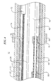
- the invention is directed to a catheter 10 having anchoring and stabilizing devices located at or near the catheter's distal end.
- the catheter comprises an elongated catheter body 12 having proximal and distal ends 13 and 15, a control handle 16 at the proximal end of the catheter body, and an anchoring device 17 located at the distal end of the catheter body 12.
- the catheter may optionally further comprise a stabilizing device 19 located at the distal end of the catheter body 12 proximal the anchoring device 17.
- the catheter body 12 comprises an elongated tubular construction having a single, axial or central lumen 18, but can optionally have multiple lumens if desired.
- the catheter body 12 is flexible, i.e., bendable, but substantially non-compressible along its length.
- the catheter body 12 can be of any suitable construction and made of any suitable material.
- a presently preferred construction comprises an outer wall 21 made of polyurethane or PEBAX (polyether block amide).
- the outer wall 21 comprises an imbedded braided mesh of stainless steel or the like to increase torsional stiffness of the catheter body 12 so that, when the control handle 16 is rotated, the distal end of the catheter body 12 will rotate in a corresponding manner.
- the outer diameter of the catheter body 12 is not critical, but is preferably no more than about 8 french, more preferably about 7 french.
- the thickness of the outer wall 21 is not critical, but is preferably thin enough so that the central lumen 18 can accommodate a puller wire, lead wires, sensor cables and any other wires, cables or tubes.
- the inner surface of the outer wall 21 is lined with a stiffening tube 27 to provide improved torsional stability.
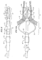
- the anchoring device 17 is located at the distal end of the catheter body 12. As shown in FIG. 2, the anchoring device 17 comprises at least two, and preferably at least four, spines 20 extending generally along a longitudinal axis of the catheter body, in radial symmetry about the catheter body. In the illustrated embodiment, the anchoring device 17 is formed by cutting slits in the circumference of a portion of a sheath 23 that generally extends the length of the catheter body and covers the catheter body 12 between the proximal and distal ends 13 and 15. In the embodiment of Fig. 2, a distal end of the sheath 23 is fixed to the distal end 15 of the catheter body 12 with the remainder of the sheath 23 proximal thereof being slidable relative to the catheter body 12.
- the slits in the sheath 23 form the spines 20 of the anchoring device 17.
- the spines 20 of the anchoring device 17 of the illustrated embodiment are generally equal in length and width and are sufficiently long such that upon compression of the anchoring device 17, the spines 20 expand radially to a degree sufficient to anchor the catheter within a tubular region 25, such as the pulmonary vein, against proximal and/or rotational movement (Fig. 2a). It is understood by one of ordinary skill in the art that the spines 20 may be formed with unequal lengths and/or unequal widths, if desired, to provide the anchoring device 17 with a nonsymmetrical radial expansion.
- the stabilizing device 19 proximal the anchoring device 17 by a non-expanding section of the sheath 27 also comprises at least two, and preferably at least four, spines 22 extending generally along a longitudinal axis of the catheter body, in radial symmetry about the catheter body 12.
- the stabilizing device 19 is constructed substantially the same as the anchoring device 17. Slits are cut about the circumference of a portion of the sheath 23 covering the catheter body 12 proximal the anchoring device 17. These slits form the spines 22 of the stabilizing device 19.
- the spines 22 of the stabilizing device 19 of the illustrated embodiment are generally equal in length and width but are generally longer than the spines 20 of the anchoring device 17 such that the spines 22 bow outwardly to a radial expansion greater than that of the spines 20. As shown in Fig. 2a, the spines 21 bow out to a greater radial expansion such that the stabilizing device 19 can be flush against an ostium 31 of the pulmonary vein to stabilize the distal end of the catheter body against distal and/or rotational movement. It is understood by one of ordinary skill in the art that the slits may be formed with unequal lengths and/or unequal widths, if desired, to provide the stabilizing device with a nonsymmetrical radial expansion.
- the sheath 23 is made of any flexible, nonconducting and noncompressible material such that upon distal movement compressing the sheath 23 toward the distal end 15 of the catheter body 12 the spines 20 of the anchoring device 17 bow outwardly to a desired degree of radial expansion, as shown in Fig 2a..
- the sheath may be made of a polymer or polymer blend or any other biocompatible material for use in a patient's body.
- the anchoring device 17 may be deployed by manually advancing the sheath 12a distally relative to the catheter body at or near the proximal end of the sheath that is outside of the patient's body, thereby advancing distally the remainder of the sheath in the patient's body which in turn compresses the anchoring device 17 at the distal end of the sheath, and radially expands the spines 20.
- the catheter body 12 comprises a stop for limiting the compression of the anchoring device.
- the catheter body may also comprise another stop for limiting the compression of the stabilizing device.
- the stops may take any suitable shape such that they limits the distal advancement of the sheath 23.
- the stops may comprise rings 30 and 32 fixedly positioned at predetermined locations on the catheter body 12.
- the ring 30 is positioned at a location between the distal end 15 of the catheter body and a proximal end of the anchoring device 17 and the ring 32 is positioned between a proximal end and a distal end of the stabilizing device 19.
- the anchoring device 17 When the proximal end of the anchoring device 17 reaches the ring 30 the anchoring device cannot compress further and is at a radial maximum; likewise, when the proximal end of the stabilizing device 19 reaches the ring 32 the stabilizing device 19 cannot compress further and is at a radial maximum. As such, radial expansion of the anchoring device 17 and/or the stabilizing device 19 is limited in accordance with the fixed positioning of the rings 30 and 32, respectively, on the catheter body 12.
- the control handle 16 may include a stopping mechanism for locking the sheath 23 in place relative to the catheter body upon reaching the desired degree of radial expansion of the anchoring device 17 and/or the stabilizing device 19, the stopping mechanism of the control handle working independently from the stop or the ring 30 of the anchoring device 17.
- the stopping mechanism of the control handle may take any suitable shape such that the sheath 23 is locked in place, preventing any further distal and/or proximal movement of the sheath 12a.
- a clamp ring 34 may be provided on a proximal end of the sheath which is adapted to releasably clamp sheath to the catheter body to prevent distal and/or proximal movement of the proximal end of the sheath.
- distal advancement of the sheath 23 relative to the catheter body 12 results in compression of the stabilizing device 19 and/or the anchoring device 17, with generally but not necessarily compression of the anchoring device 17 occurring before compression of the stabilizing device 19.
- the catheter is advanced in its atraumatic configuration (see Fig. 2) in the patient's body until it reaches the heart chamber.
- the distal end of the catheter body is placed inside the tubular region 25, e.g., the pulmonary vein, and the sheath 23 is advanced distally such that the anchoring device 17 is radially expanded to an appropriate level or until the proximal end of the anchoring device encounters the ring 30.
- the stabilizing device 19 is also radially expanded by distal advancement of the sheath to an appropriate level or until the proximal end of the stabilizing device encounters the ring 32. Accordingly, as shown in FIG. 2A, the radial expansion of the anchoring device secures the anchoring device to the inside of the pulmonary vein against rotational and/or proximal movement while the radial expansion of the stabilizing device presses the stabilizing device against the ostium 31 to prevent or at least minimize rotational and/or distal movement. With the distal end 15 of the catheter body 12 secured in this manner to the tubular region 25, the catheter is ready for ablation by means of a distal electrode 40 and/or an ultrasonic ablation member 42, as described in detail further below.
- the stabilizing device 19 absorbs any excess pressure exerted by the continued advancement of the sheath 23.
- This construction prevents the anchoring device 17 from absorbing any excess pressure, thereby preventing the anchoring device 17 from causing any undue damage to the walls of the tubular region.
- the stop such as the rings 30 and 32, may be used to prevent the anchoring device 17 and/or stabilizing device 19 from absorbing any excess pressure.
- the stopping mechanism e.g., the clamp ring 34 may also be used to lock the stabilizing device 19 in radial expansion to press on the ostium of the pulmonary vein.
- the clamp ring 34 is released and the sheath 23 is moved manually by the user in the proximal direction to minimize and reduce the radial expansion of the anchoring device 17 and the stabilizing device 19. Having returned to its atraumatic configuration, the distal end 15 can be readily removed from the tubular region and reposition in another tubular region or removed altogether from the patient's body.
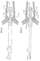
- a sheath 23a covers a distal end 15a of a catheter body 12a which is adapted with a telescoping portion 54 having two telescoping members 56 and 58.
- a sheath 23a has a shortened length, extending from a distal end 60 of the telescoping portion 54 to only proximally past a proximal end 62 of the telescoping portion 54.
- a distal end of the sheath 23a is fixed to the distal end 60 of the telescoping portion and a proximal end of the sheath is fixed to the distal end of the catheter body 15.
- An anchoring device 17a formed from a distal portion of the sheath 23a is located generally on the telescoping member 54 and a stabilizing device 19a formed from a proximal portion of the sheath is located on the telescoping member 56.
- a non-expanding section 27a of the sheath separates the devices 17a and 19a.
- slits are cut around the circumference of the sheath 23a, forming spines 20a and 22a of the anchoring device 17a and the stabilizing device 19a, which can be generally equal or generally unequal in length and width.
- the stabilizing device 19a proximal the anchoring device 17a is longer than the anchoring device 17a, but is sufficiently short to allow room on the distal end of the catheter body 12 for an ablation device to be mounted proximal the stabilizing device 19a, such as ring electrodes discussed in detail further below.
- a noncompressible and generally stiff puller cable 60 extends through a lumen in the telescoping portion and the lumen 18a of the catheter body 12a and is fixed at its distal end to the distal end of the telescoping portion 54 which in turn is fixed to the distal end of the sheath 23a.
- a proximal end of the puller cable 60 is located in the control handle 16 and connected to suitable control mechanism that moves the puller cable 60 proximally and distally. Proximal movement of the puller cable 60 results in compression of the anchoring device 17a and/or the stabilizing device 19a.
- the telescoping member 56 may include a stop, such as a ring 30a, for preventing further radial expansion of the anchoring device 17a after reaching a predetermined degree of radial expansion.
- the telescoping member 58 may include a stop, such as a ring 32a, for preventing further radial expansion of the stabilizing device 19a after reaching a predetermined degree of radial expansion.
- the rings 30a and 32a are fixedly positioned on the respective telescoping members 56 and 58 such that when the ring 32a encounters the distal end of the catheter body 12, the telescoping member 58 is prevented from further proximal movement, and/or when the ring 30a encounters a distal end of the telescoping member 58 the telescoping member 56 is prevented from further proximal movement.
- proximal movement of the puller cable 60 drawing in the distal end of the telescoping member 56 results in compression of the stabilizing device 19a and/or the anchoring device 17a, with generally but not necessarily compression of the stabilizing device 19a occurring before compression of the anchoring device 17a.
- the catheter is advanced in its atraumatic configuration (see Fig. 3) in the patient's body until it reaches the heart chamber.
- the distal end of the telescoping member 56 is placed inside the tubular region 25, e.g., the pulmonary vein, and the puller cable 60 is drawn proximally by suitable manipulation of the control handle 16 which in turn draws proximally the telescoping members 56 and 58.
- the tubular region 25 e.g., the pulmonary vein
- the stabilizing device 19a is radially expanded to an appropriate level or until the ring 32a encounters the distal end 15 of the catheter body 12 and the anchoring device 17a is radially expanded to an appropriate level or until the ring 30a encounters the proximal end of the telescoping member 58. Accordingly, the radial expansion of the anchoring device 17a secures the anchoring device to the inside of the tubular region 25, e.g., a pulmonary vein, against rotational and/or proximal movement while the radial expansion of the stabilizing device 19a presses the stabilizing device against the ostium 31 of the tubular region to prevent or at least minimize rotational and/or distal movement. With the distal end of its catheter body secured in this manner, the catheter is ready for ablation by means of a distal electrode 40a and/or an ultrasonic ablation member 42a, as described in detail further below.
- the stabilizing device 19a absorbs any excess pressure exerted by the continued advancement of the sheath 23a. This construction prevents the anchoring device 17a from absorbing any excess pressure, thereby preventing the anchoring device 17a from causing any undue damage to the walls of the tubular region.
- the stops such as the rings 30a and 32a, may be used to prevent the anchoring device 17a and/or stabilizing device 19a from absorbing any excess pressure.
- the mechanism controlling the puller cable 60 may also be adapted to lock the cable in place to prevent distal and/or proximal movement after the devices 17a and 19a have been deployed at or near the ostium of the pulmonary vein.
- the puller cable 60 attached to the distal end of the sheath 23a controls the radial expansion of both the anchoring device 17a and the stabilizing device 19a.
- Proximal movement of the puller cable 60 results in compression of both the anchoring device 17a and the stabilizing device 19a.
- This compression causes the spines 20a and 22a to bow outwardly, thereby causing the anchoring device 17a and the stabilizing device 19 to expand radially.
- the curvature of the spines 20 and 20a, and thus the degree of radial expansion of the anchoring device 17 and the stabilizing device 19, can be adjusted by controlling the proximal distance by which the puller cable 60 is pulled.
- the control handle 16 is manipulated to advance the puller wire 60 so as to minimize and reduce the radial expansion of the anchoring device 17 and the stabilizing device 19.
- the puller cable 60 has sufficient stiffness and/or is appropriately supported by its own sheath such that it can adequately support and maintain the telescoping portion 54 in its distally extended configuration from the distal end of the catheter body when the catheter body is being advanced in the patient's body and also adequately extend the telescoping members 56 and 58 to return the distal end to its atraumatic configuration. Having returned to its atraumatic configuration, the catheter body 12 can be readily removed from the tubular region and repositioned in another tubular region or removed altogether from the patient's body.
- the telescoping portion 54 may also consist of merely one telescoping member or more than two telescoping members, as desired or appropriate to vary the compression of the anchoring device and/or the stabilizing device.
- the ring 30 may be positioned on the telescoping 54 proximal of the section 27a, as desired or appropriate to limit the compression of the stabilizing device.
- the maximum distal extension of the telescoping portion regardless of the plurality of telescoping member(s) is limited by the length of the puller cable 60 and/or the provision of a lip or flange at the corresponding ends of adjacent telescoping members which prevents the telescoping members from disconnecting.
- the radial expansion of the anchoring device and the stabilizing device is adjustable.
- the ability to adjust the radial expansion of the anchoring device enables the exertion of varying degrees of pressure on the walls of the tubular region, e.g. the pulmonary vein. For example, a physician can manipulate the catheter to expand the devices until enough pressure is exerted on the walls of the tubular region to anchor the catheter within that region, and then activate the stopping mechanism to lock the devices in their position. Once locked, no more, or no less, pressure can be exerted on the walls of the tubular region and/or the ostium.
- the ability to adjust the radial expansion of the anchoring device enables the devices to conform to many different shapes within any tubular region or ostium.
- the ability to control the pressure exerted on the walls of the tubular region and the ostium enables the anchoring and stabilizing of the catheter against both translational and rotational movement. Because the stabilizing device is located proximal the anchoring device, the stabilizing device is capable of absorbing any excess pressure that may inadvertently be exerted on the anchoring device. Such a construction prevents the anchoring device from causing any undue or excessive damage to the walls of the tubular region.
- a catheter body 12c may be configured with merely an anchoring device 17c formed from a sheath 23c whose distal end is fixed to a distal end 15c of the catheter body.
- a maximum radial expansion of the device 17c is set by a ring 30c fixedly positioned on the catheter body 12c.
- a catheter body 12d may be configured with merely an anchoring device 17d formed from a sheath 23d whose distal end is fixed to a distal end of a telescoping member 56d that is moved distally and proximally by a puller cable 60d.
- a maximum radial expansion of the device 17d is set by a ring 30d fixedly positioned on the member 56d.
- an ultrasonic transducer and protective balloon may be mounted proximal of the anchoring device, if desired.
- ring electrodes 28 may optionally be mounted on the sheath of either catheter embodiment.
- ring electrodes 28 are preferably mounted on the sheath distal the anchoring device and proximal the stabilizing device.
- the ring electrodes 28 may be used for mapping and/or ablation.
- each of the ring electrodes 28 is electrically connected to an appropriate mapping or monitoring system and/or source of ablation energy by means of an electrode lead wire 29, as shown in FIGs. 4 and 5.
- Each electrode lead wire 29 extends through the control handle 16 and 16a, through a lumen in the catheter body 12 and 12a, and is connected to its corresponding ring electrode 28 (of which only one is shown in FIGS. 4 and 5).
- Each lead wire 29 is covered by a non-conductive covering and is attached to its corresponding ring electrode 28 by any suitable method.
- a preferred method for attaching a lead wire 29 to a ring electrode 28 involves first making a small hole through the wall of the sheath 23 and 23a. Such a hole can be created, for example, by inserting a needle through the sheath and heating the needle sufficiently to form a permanent hole. The lead wire 29 is then drawn through the hole by using a microhook or the like. The end of the lead wire 29 is then stripped of any coating and welded to the underside of the ring electrode 28, which is then slid into position over the hole and fixed in place with polyurethane glue or the like.
- each ring electrode 28 is formed by wrapping a lead wire 29 around the sheath 23 and 23a a number of times and stripping the lead wire 29 of its own insulated coating on its outwardly facing surfaces.
- each lead wire 29 is significantly longer than the length between the ring electrode and the connection of the lead wire 29 to the control handle.
- This extra length of the lead wires 29 allows the lead wires 29 to move with the sheath 23 distally to radially expand the spines 20 of the anchoring device 17 and/or the spines 22 of the stabilizing device 19. When the sheath is so moved, the lead wires 29 pass between the sheath 23 and the catheter body 12.
- the extra length of the lead wires 29 may be contained in the control handle 16 by a mechanism capable of deploying the extra length as needed.
- the catheter body may carry a circumferential ablation device, such as an ultrasound transducer 65 mounted within the stabilization device 19 and 19a.
- the stabilization device is covered with an expandable balloon 67 whose distal and proximal ends are fixed to the sheath 23 and 23a to seal the ultrasound transducer 65 from blood and other fluids present in the heart and the tubular region.
- An example of such an ultrasound transducer and balloon mechanism suitable for use in the present invention is disclosed in US-6780183.
- a suitable embodiment of the stabilizing device 19 preferably comprises at least two, but no more than three spines. Such a configuration allows the ultrasound transducer 65 to transmit ablation energy to the target site, but still stabilizes the catheter, e.g., about the ostium of the pulmonary vein.
- the ultrasound transducer 65 is mounted on the sheath 23 and 23a proximal the stabilizing device 19 and 19a and is covered by an inflatable balloon 67 fixedly attached at its proximal and distal ends to the sheath.
- the stabilizing device 19 and 19a preferably comprises at least two, but no more than 3 spines, to enable the transducer 31 to transmit ablation energy around the stabilizing device 19.
- the catheter optionally further comprises a means for deflecting the distal end of the catheter body 12 and 12a.
- the deflection means comprises a puller wire 40 anchored at its distal end to the distal end of the catheter body, as shown in FIGs. 4 and 5.
- the puller wire 40 is made of any suitable metal, such as stainless steel or Nitinol, and is preferably coated with Teflon or the like. The coating imparts lubricity to the puller wire 40.
- the puller wire preferably has a diameter ranging from about 0.152 to about 0.254 mm (about 0.006 to about 0.010 inches).
- a compression coil 42 is situated within the catheter body in surrounding relation to the puller wire 40.
- the compression coil extends from the proximal end of the catheter to the distal end of the catheter.
- the compression coil 42 is made of any suitable metal, preferably stainless steel.
- the compression coil 42 is tightly wound on itself to provide flexibility, i.e., bending, but to resist compression.
- the inner diameter of the compression coil 42 is preferably slightly larger than the diameter of the puller wire 40. For example, when the puller wire 42 has a diameter of about 0.178 mm (0.007 inches), the compression coil 42 preferably has an inner diameter of about 0.203 mm (0.008 inches).
- the Teflon coating on the puller wire 40 allows it to slide freely within the compression coil 42.
- the outer surface of the compression coil 42 is covered by a flexible, non-conductive sheath 44 to prevent contact between the compression coil 42 and the lead wires 29 within the catheter body 12.
- a non-conductive sheath 44 made of polyimide is presently preferred.
- the compression coil 42 is anchored at its proximal end to the proximal end of the stiffening tube 22 of the catheter body 12 by glue joint 50 and at its distal end to the distal end of the catheter body 12 by glue joint 51.
- Both glue joints 50 and 51 preferably comprise polyurethane glue or the like.
- the glue may be applied by means of a syringe or the like through a hole made between the outer surface of the catheter body 12 and the single lumen 18. Such a hole may be formed, for example, by a needle or the like that punctures the wall of the catheter body 12 and the stiffening tube 22 which is heated sufficiently to make a permanent hole.
- the glue is then introduced through the hole to the outer surface of the compression coil 42 and wicks around the outer circumference to form a glue joint about the entire circumference of the compression coil 42.
- the puller wire 40 extends through the lumen of the catheter body 12 into the distal end of the catheter body 12.
- the distal end of the puller wire 40 is anchored within the distal end of the catheter body 12.
- the puller wire 40 extends through a plastic, preferably Teflon, sheath 45, which prevents the puller wire 40 from cutting into the wall of the catheter body 12 when the distal end of the catheter body 12 is deflected.
- the puller wire 40 is deflected upon longitudinal movement of the puller wire 40 relative to the catheter body 12.
- An electromagnetic sensor 72 may be contained within the distal end of the catheter body 12.
- the electromagnetic sensor 72 may extend from the distal end of the catheter body 12 to the distal end of the anchoring device 17. Alternatively, the electromagnetic sensor 72 may extend partially into the anchoring device 17.
- the electromagnetic sensor 72 is mounted to the distal end of the catheter body 12 by any suitable means, e.g. by polyurethane glue or the like.
- the electromagnetic sensor 72 is connected to an electromagnetic sensor cable 74, which extends through the lumen in the catheter body 12, and out through the control handle 16.
- the electromagnetic sensor cable 74 comprises multiple wires encased within a plastic covered sheath.
- the sensor cable 74 is connected to a circuit board (not shown).
- the circuit board amplifies the signal received from the electromagnetic sensor 72 and transmits it to a computer in a form understandable by the computer. Because the catheter is designed for a single use only, the circuit board may contain an EPROM chip which shuts down the circuit board approximately 24 hours after the catheter has been used. This prevents the catheter, or at least the electromagnetic sensor from being used twice.
- a preferred electromagnetic sensor 72 has a length of from about 6 mm to about 7 mm and a diameter of about 1.3 mm.
- Suitable control handle mechanisms for operating the puller cable 60 and/or the puller wire 40 may be found in US-6210407, US-6171277 and US-6198974.
Abstract
Description
- The present invention is directed to a mapping and/or ablation catheter with a multi-spine anchoring device and, more particularly, to a mapping and/or ablation catheter with a multi-spine anchoring device for use in a tubular region in or near the heart.
- Electrode catheters have been in common use in medical practice for many years. They are used to stimulate and map electrical activity in the heart and to ablate sites of aberrant electrical activity. In use, an electrode is inserted into a major vein or artery, such as the femoral artery, and guided into the chamber of the heart which is of concern. Often, the target area of the heart is a tubular region, such as the pulmonary vein, the coronary sinus, the superior vena cava and the inferior vena cava.
- Electrode catheters are used to identify and/or ablate tissue in the region of the heart exhibiting the aberrant electrical activity. Often, electrode catheters are capable of both mapping the tissue to locate the site of aberrant electrical activity, and ablating the identified tissue. The ablation of this tissue isolates this tissue from the rest of the heart, thereby preventing the aberrant electrical pathways from extending into other areas of the heart. One area of the heart where such ablation is typically desirable is the pulmonary vein. Several catheters, such as those described in US-6024740 and US-6117101, are designed to ablate circumferential lesions inside the pulmonary vein. These catheters comprise an ablation element, such as an ultrasound transducer, surrounded by an inflatable balloon. To ablate the desired circumferential lesion, the balloon is inflated to anchor the catheter within the pulmonary vein, and the transducer is activated to form a circumferential lesion in the tissue engaged by the balloon.
- Although they are effective for creating circumferential lesions in heart tissue, these balloon catheters have several disadvantages. For example, the balloon often is situated incorrectly within the pulmonary vein and/or becomes dislodged from the anchoring site. Also, the balloon does not allow blood to flow past it, resulting in a build up of blood at the distal end of the balloon, causing the blood to clot. Accordingly, a mapping and/or ablation catheter having a stabilized anchoring mechanism that enables blood flow and prevents clots is desirable.
- The present invention is directed to a catheter having a catheter body whose distal end has an anchoring device and a stabilizing device that are adapted to respectively sit in and sit outside of an opening of a tubular region, such as an ostium of a pulmonary vein. A sheath covering the catheter body forms the anchoring device and the stabilizing device. In particular, the anchoring device comprises a plurality of slits cut into the sheath where the slits create spines of generally equal length and width in the sheath. Similarly, the stabilizing device comprises a plurality of slits cut into the sheath at a location proximal the anchoring device. The slits create spines of generally equal length and width in the sheath, the spines of the stabilizing device being longer than the spines of the anchoring device.
- In one embodiment, the sheath is fixed at its distal end to the distal end of the catheter body. The spines of the anchoring device and the stabilizing device are deployed by distal movement of the sheath relative to the catheter body. Such distal movement of the sheath causes the spines of the anchoring and stabilizing devices to bow outwardly resulting in radial expansion of the anchoring and stabilizing devices. The distal end of catheter body is positioned in or near the heart such that the anchoring device is inside a tubular region, such as the pulmonary vein, and the stabilizing device is proximately and proximally to the ostium outside of the same tubular region. Upon radial expansion of the anchoring device, the spines of the anchoring device exert pressure against the walls of the tubular region thereby generally anchoring the distal end of the catheter body inside the tubular region against proximal and/or radial movement relative to the tubular region. Upon radial expansion of the spines of the stabilizing assembly, the spines of the stabilizing device exert pressure against the ostium of the tubular region thereby generally stabilizing the distal end of the catheter body against distal and/or radial movement relative to the tubular region. Accordingly, the pressure exerted on the walls of the tubular region by the anchoring device and on the ostium by the stabilizing device minimizes, if not prevents, the distal end of the catheter body against both translational and rotational movement. In particular, the pressure exerted on the ostium of the tubular region by the stabilizing device stabilizes the catheter within the heart for delivery of ablation energy to treat the desired area of the heart.
- In an alternative embodiment, the distal end of the catheter body has a telescoping portion with a proximal telescoping member and a distal telescoping member. The sheath covers the proximal and distal telescoping members by extending from a distal end of the distal telescoping member to at least a proximal end of the proximal telescoping member. The distal end of the sheath is affixed to the distal end of the distal telescoping member and the proximal end of the sheath is affixed to the distal end of the catheter body proximal of the proximal telescoping member. A puller cable is attached to the distal end of the sheath which is fixed to the distal end of the distal telescoping member for effecting radial expansion of the anchoring and stabilizing devices. In particular, proximal movement of the puller cable draws in the distal and proximal telescoping members for radially expanding the spines of the anchoring and stabilizing devices.
- In either embodiment, the degree of radial expansion of both the anchoring and stabilizing devices is adjustable by adjusting the amount of relative translational movement between the sheath and the catheter body. The ability to adjust the degree of radial expansion of the anchoring and stabilizing devices enables the exertion of varying degrees of pressure on either the walls or the ostium of the tubular region. Accordingly, the anchoring and stabilizing devices are capable of conforming to differently shaped tubular regions. Also, in order to prevent undesired damage to the walls of the tubular region, the stabilizing device absorbs any excess pressure inadvertently exerted on the anchoring device. To that end, stops, for example in the form of rings fixedly mounted on the catheter body or the telescoping portion limit the amount of radial expansion of the anchoring device and/or the stabilizing device.
- In another embodiment, a catheter comprises: an elongated catheter body having proximal and distal ends and at least one lumen extending therethrough; a non-conductive sheath mounted in surrounding relation to the catheter body, wherein the non-conductive sheath is slidable relative to the catheter body; an anchoring device comprising a plurality of spines formed by cutting longitudinal slits about a circumference of the distal end of the non-conductive sheath; a stabilizing device comprising a plurality of spines formed by cutting longitudinal slits about a circumference of the distal end of the non-conductive sheath at a location proximal the anchoring device; and a control handle mounted on the proximal end of the catheter body; wherein distal movement of the non-conductive sheath relative to the catheter body results in radial expansion of the spines of the anchoring device and the spines of the stabilizing device.
- In a further embodiment, a catheter comprises: an elongated catheter body having proximal and distal ends and at least one lumen extending therethrough; a non-conductive sheath mounted in surrounding relation to the catheter body, wherein the non-conductive sheath is fixedly attached to the catheter body except at its distal end; an anchoring device comprising a plurality of spines formed by cutting longitudinal slits about a circumference of the distal end of the non-conductive sheath; a puller cable having proximal and distal ends, its distal end fixedly attached to the distal end of the non-conductive sheath; and a control handle mounted on the proximal end of the catheter body; wherein longitudinal movement of the puller cable relative to the catheter body results in radial expansion of the spines of the anchoring device. Each spine may have the the same length. Each spine may have the same width.
- The catheter may further comprises a stabilizing device comprising a plurality of spines formed by cutting longitudinal slits about a circumference of the distal end of the non-conductive sheath at a location on the sheath proximal the anchoring device, wherein longitudinal movement of the puller cable relative to the catheter body results in radial expansion of the spines of the stabilizing device. The spines of the stabilizing device may be longer than the spines of the anchoring device. The spines of the stabilizing device may have the same length. The spines of the stabilizing device may have the same width.
- The catheter may further comprise means for deflecting the distal end of the catheter body, the means for deflecting comprising a puller wire having a proximal end and a distal end, the proximal end of the puller wire being fixedly attached in the control handle, and the distal end of the puller wire is fixedly attached to the distal end of the catheter body, whereby longitudinal movement of puller wire results in deflection of the distal end of the catheter.
- The catheter may further comprise an electromagnetic sensor mounted in the distal end of the catheter body.
- According to another embodiment, a catheter comprises: an elongated catheter body having proximal and distal ends and at least one lumen extending therethrough; a non-conductive sheath mounted in surrounding relation to the catheter body, wherein the non-conductive sheath is fixedly attached to the catheter body except at its distal end; an anchoring device comprising a plurality of spines formed by cutting longitudinal slits about a circumference of the distal end of the non-conductive sheath; a stabilizing device comprising a plurality of spines formed by cutting longitudinal slits about a circumference of the distal end of the non-conductive sheath at a location proximal the anchoring device; a puller cable having proximal and distal ends, its distal end fixedly attached to the distal end of the non-conductive sheath; and a control handle mounted on the proximal end of the catheter body; wherein longitudinal movement of the puller cable relative to the catheter body results in radial expansion of the spines of the anchoring device.
- Embodiments of the invention will now be described by way of example with reference to the accompanying drawings, in which:
- FIG. 1 is a perspective view of an embodiment of a catheter according to the present invention;
- FIG. 2 is an enlarged perspective view of the distal end of the catheter body according to one embodiment of the invention;
- FIG. 2A is an enlarged perspective view of the catheter of FIG. 2, as deployed in a tubular region of a patient's heart;
- FIG. 3 is an enlarged perspective view of the distal end of the catheter body according to another embodiment of the invention;
- FIG. 3A is an enlarged perspective view of the catheter of FIG. 3, as deployed in a tubular region of a patient's heart;
- FIG. 4 is a longitudinal cross-sectional view of a portion of a catheter body of FIGS. 2 and 2A;
- FIG. 5 is a longitudinal cross-sectional view of a portion of a catheter body of FIGS. 3 and 3A;
- FIG. 6 is an enlarged perspective view of the distal end of the catheter body according to another embodiment of the invention
- FIG. 6A is an enlarged perspective view of the catheter of FIG. 6, as deployed in a tubular region of a patient's heart;
- FIG. 7 is an enlarged perspective view of the distal end of the catheter body according to another embodiment of the invention;
- FIG. 7A is an enlarged perspective view of the catheter of FIG. 7, as deployed in a tubular region of a patient's heart;
- FIG. 8 is a perspective view of another embodiment of a catheter of the present invention without a stabilizing device; and
- FIG. 9 is a perspective view of yet another embodiment of a catheter of the present invention without a stabilizing device.
- The invention is directed to a catheter 10 having anchoring and stabilizing devices located at or near the catheter's distal end. As shown in FIG. 1, the catheter comprises an
elongated catheter body 12 having proximal anddistal ends 13 and 15, acontrol handle 16 at the proximal end of the catheter body, and ananchoring device 17 located at the distal end of thecatheter body 12. The catheter may optionally further comprise a stabilizingdevice 19 located at the distal end of thecatheter body 12 proximal theanchoring device 17. - As shown in Fig. 5, the
catheter body 12 comprises an elongated tubular construction having a single, axial orcentral lumen 18, but can optionally have multiple lumens if desired. Thecatheter body 12 is flexible, i.e., bendable, but substantially non-compressible along its length. Thecatheter body 12 can be of any suitable construction and made of any suitable material. A presently preferred construction comprises anouter wall 21 made of polyurethane or PEBAX (polyether block amide). Theouter wall 21 comprises an imbedded braided mesh of stainless steel or the like to increase torsional stiffness of thecatheter body 12 so that, when the control handle 16 is rotated, the distal end of thecatheter body 12 will rotate in a corresponding manner. - The outer diameter of the
catheter body 12 is not critical, but is preferably no more than about 8 french, more preferably about 7 french. Likewise, the thickness of theouter wall 21 is not critical, but is preferably thin enough so that thecentral lumen 18 can accommodate a puller wire, lead wires, sensor cables and any other wires, cables or tubes. If desired, the inner surface of theouter wall 21 is lined with a stiffeningtube 27 to provide improved torsional stability. - The anchoring
device 17 is located at the distal end of thecatheter body 12. As shown in FIG. 2, the anchoringdevice 17 comprises at least two, and preferably at least four,spines 20 extending generally along a longitudinal axis of the catheter body, in radial symmetry about the catheter body. In the illustrated embodiment, the anchoringdevice 17 is formed by cutting slits in the circumference of a portion of asheath 23 that generally extends the length of the catheter body and covers thecatheter body 12 between the proximal anddistal ends 13 and 15. In the embodiment of Fig. 2, a distal end of thesheath 23 is fixed to thedistal end 15 of thecatheter body 12 with the remainder of thesheath 23 proximal thereof being slidable relative to thecatheter body 12. The slits in thesheath 23 form thespines 20 of theanchoring device 17. Thespines 20 of theanchoring device 17 of the illustrated embodiment are generally equal in length and width and are sufficiently long such that upon compression of theanchoring device 17, thespines 20 expand radially to a degree sufficient to anchor the catheter within atubular region 25, such as the pulmonary vein, against proximal and/or rotational movement (Fig. 2a). It is understood by one of ordinary skill in the art that thespines 20 may be formed with unequal lengths and/or unequal widths, if desired, to provide theanchoring device 17 with a nonsymmetrical radial expansion. - The stabilizing
device 19 proximal theanchoring device 17 by a non-expanding section of thesheath 27 also comprises at least two, and preferably at least four,spines 22 extending generally along a longitudinal axis of the catheter body, in radial symmetry about thecatheter body 12. The stabilizingdevice 19 is constructed substantially the same as the anchoringdevice 17. Slits are cut about the circumference of a portion of thesheath 23 covering thecatheter body 12 proximal theanchoring device 17. These slits form thespines 22 of the stabilizingdevice 19. Thespines 22 of the stabilizingdevice 19 of the illustrated embodiment are generally equal in length and width but are generally longer than thespines 20 of theanchoring device 17 such that thespines 22 bow outwardly to a radial expansion greater than that of thespines 20. As shown in Fig. 2a, thespines 21 bow out to a greater radial expansion such that the stabilizingdevice 19 can be flush against anostium 31 of the pulmonary vein to stabilize the distal end of the catheter body against distal and/or rotational movement. It is understood by one of ordinary skill in the art that the slits may be formed with unequal lengths and/or unequal widths, if desired, to provide the stabilizing device with a nonsymmetrical radial expansion. - The
sheath 23 is made of any flexible, nonconducting and noncompressible material such that upon distal movement compressing thesheath 23 toward thedistal end 15 of thecatheter body 12 thespines 20 of theanchoring device 17 bow outwardly to a desired degree of radial expansion, as shown in Fig 2a.. The sheath may be made of a polymer or polymer blend or any other biocompatible material for use in a patient's body. In the illustrated embodiment, the anchoringdevice 17 may be deployed by manually advancing thesheath 12a distally relative to the catheter body at or near the proximal end of the sheath that is outside of the patient's body, thereby advancing distally the remainder of the sheath in the patient's body which in turn compresses theanchoring device 17 at the distal end of the sheath, and radially expands thespines 20. - Preferably, the
catheter body 12 comprises a stop for limiting the compression of the anchoring device. The catheter body may also comprise another stop for limiting the compression of the stabilizing device. The stops may take any suitable shape such that they limits the distal advancement of thesheath 23. For example, as shown in FIGS 2 and 2a, the stops may compriserings catheter body 12. In particular, thering 30 is positioned at a location between thedistal end 15 of the catheter body and a proximal end of theanchoring device 17 and thering 32 is positioned between a proximal end and a distal end of the stabilizingdevice 19. When the proximal end of theanchoring device 17 reaches thering 30 the anchoring device cannot compress further and is at a radial maximum; likewise, when the proximal end of the stabilizingdevice 19 reaches thering 32 the stabilizingdevice 19 cannot compress further and is at a radial maximum. As such, radial expansion of theanchoring device 17 and/or the stabilizingdevice 19 is limited in accordance with the fixed positioning of therings catheter body 12. - Longitudinal movement of the
sheath 23 is accomplished, for example, by manual distal advancement by the user, or by suitable manipulation of the control handle 16. If desired, the control handle 16 may include a stopping mechanism for locking thesheath 23 in place relative to the catheter body upon reaching the desired degree of radial expansion of theanchoring device 17 and/or the stabilizingdevice 19, the stopping mechanism of the control handle working independently from the stop or thering 30 of theanchoring device 17. The stopping mechanism of the control handle may take any suitable shape such that thesheath 23 is locked in place, preventing any further distal and/or proximal movement of thesheath 12a. For example, a clamp ring 34 may be provided on a proximal end of the sheath which is adapted to releasably clamp sheath to the catheter body to prevent distal and/or proximal movement of the proximal end of the sheath. - In accordance with the present invention, distal advancement of the
sheath 23 relative to thecatheter body 12 results in compression of the stabilizingdevice 19 and/or theanchoring device 17, with generally but not necessarily compression of theanchoring device 17 occurring before compression of the stabilizingdevice 19. In use, the catheter is advanced in its atraumatic configuration (see Fig. 2) in the patient's body until it reaches the heart chamber. There, the distal end of the catheter body is placed inside thetubular region 25, e.g., the pulmonary vein, and thesheath 23 is advanced distally such that the anchoringdevice 17 is radially expanded to an appropriate level or until the proximal end of the anchoring device encounters thering 30. The stabilizingdevice 19 is also radially expanded by distal advancement of the sheath to an appropriate level or until the proximal end of the stabilizing device encounters thering 32. Accordingly, as shown in FIG. 2A, the radial expansion of the anchoring device secures the anchoring device to the inside of the pulmonary vein against rotational and/or proximal movement while the radial expansion of the stabilizing device presses the stabilizing device against theostium 31 to prevent or at least minimize rotational and/or distal movement. With thedistal end 15 of thecatheter body 12 secured in this manner to thetubular region 25, the catheter is ready for ablation by means of adistal electrode 40 and/or anultrasonic ablation member 42, as described in detail further below. - In accordance with the present invention, when the
anchoring device 17 reaches its maximum degree of radial expansion, the stabilizingdevice 19 absorbs any excess pressure exerted by the continued advancement of thesheath 23. This construction prevents theanchoring device 17 from absorbing any excess pressure, thereby preventing theanchoring device 17 from causing any undue damage to the walls of the tubular region. Alternatively, the stop, such as therings anchoring device 17 and/or stabilizingdevice 19 from absorbing any excess pressure. The stopping mechanism, e.g., the clamp ring 34 may also be used to lock the stabilizingdevice 19 in radial expansion to press on the ostium of the pulmonary vein. - When the
distal end 15 of thecatheter body 12 needs to be withdrawn from thetubular region 25, the clamp ring 34 is released and thesheath 23 is moved manually by the user in the proximal direction to minimize and reduce the radial expansion of theanchoring device 17 and the stabilizingdevice 19. Having returned to its atraumatic configuration, thedistal end 15 can be readily removed from the tubular region and reposition in another tubular region or removed altogether from the patient's body. - In an alternative embodiment, shown in FIG. 4, a
sheath 23a covers adistal end 15a of acatheter body 12a which is adapted with atelescoping portion 54 having two telescopingmembers sheath 23a has a shortened length, extending from adistal end 60 of thetelescoping portion 54 to only proximally past a proximal end 62 of thetelescoping portion 54. A distal end of thesheath 23a is fixed to thedistal end 60 of the telescoping portion and a proximal end of the sheath is fixed to the distal end of thecatheter body 15. Ananchoring device 17a formed from a distal portion of thesheath 23a is located generally on the telescopingmember 54 and a stabilizingdevice 19a formed from a proximal portion of the sheath is located on the telescopingmember 56. Anon-expanding section 27a of the sheath separates thedevices sheath 23a, formingspines anchoring device 17a and the stabilizingdevice 19a, which can be generally equal or generally unequal in length and width. The stabilizingdevice 19a proximal theanchoring device 17a is longer than theanchoring device 17a, but is sufficiently short to allow room on the distal end of thecatheter body 12 for an ablation device to be mounted proximal the stabilizingdevice 19a, such as ring electrodes discussed in detail further below. - For deploying the
anchoring device 17a and/or the stabilizingdevice 19a into their radially expanded configuration, a noncompressible and generallystiff puller cable 60 extends through a lumen in the telescoping portion and thelumen 18a of thecatheter body 12a and is fixed at its distal end to the distal end of thetelescoping portion 54 which in turn is fixed to the distal end of thesheath 23a. A proximal end of thepuller cable 60 is located in the control handle 16 and connected to suitable control mechanism that moves thepuller cable 60 proximally and distally. Proximal movement of thepuller cable 60 results in compression of theanchoring device 17a and/or the stabilizingdevice 19a. This compression causes thespines spines anchoring device 17a and the stabilizingdevice 19a, can be adjusted by controlling the proximal distance in which thepuller cable 60 is pulled. The telescopingmember 56 may include a stop, such as aring 30a, for preventing further radial expansion of theanchoring device 17a after reaching a predetermined degree of radial expansion. Likewise, the telescopingmember 58 may include a stop, such as aring 32a, for preventing further radial expansion of the stabilizingdevice 19a after reaching a predetermined degree of radial expansion. Therings respective telescoping members ring 32a encounters the distal end of thecatheter body 12, the telescopingmember 58 is prevented from further proximal movement, and/or when thering 30a encounters a distal end of the telescopingmember 58 thetelescoping member 56 is prevented from further proximal movement. - In accordance with the present invention, proximal movement of the
puller cable 60 drawing in the distal end of the telescopingmember 56 results in compression of the stabilizingdevice 19a and/or theanchoring device 17a, with generally but not necessarily compression of the stabilizingdevice 19a occurring before compression of theanchoring device 17a. In use, the catheter is advanced in its atraumatic configuration (see Fig. 3) in the patient's body until it reaches the heart chamber. There, the distal end of the telescopingmember 56 is placed inside thetubular region 25, e.g., the pulmonary vein, and thepuller cable 60 is drawn proximally by suitable manipulation of the control handle 16 which in turn draws proximally thetelescoping members device 19a is radially expanded to an appropriate level or until thering 32a encounters thedistal end 15 of thecatheter body 12 and theanchoring device 17a is radially expanded to an appropriate level or until thering 30a encounters the proximal end of the telescopingmember 58. Accordingly, the radial expansion of theanchoring device 17a secures the anchoring device to the inside of thetubular region 25, e.g., a pulmonary vein, against rotational and/or proximal movement while the radial expansion of the stabilizingdevice 19a presses the stabilizing device against theostium 31 of the tubular region to prevent or at least minimize rotational and/or distal movement. With the distal end of its catheter body secured in this manner, the catheter is ready for ablation by means of adistal electrode 40a and/or an ultrasonic ablation member 42a, as described in detail further below. - When the
anchoring device 17a reaches its maximum degree of radial expansion, the stabilizingdevice 19a absorbs any excess pressure exerted by the continued advancement of thesheath 23a. This construction prevents theanchoring device 17a from absorbing any excess pressure, thereby preventing theanchoring device 17a from causing any undue damage to the walls of the tubular region. Alternatively, the stops, such as therings anchoring device 17a and/or stabilizingdevice 19a from absorbing any excess pressure. The mechanism controlling thepuller cable 60 may also be adapted to lock the cable in place to prevent distal and/or proximal movement after thedevices - Accordingly, the
puller cable 60 attached to the distal end of thesheath 23a controls the radial expansion of both theanchoring device 17a and the stabilizingdevice 19a. Proximal movement of thepuller cable 60 results in compression of both theanchoring device 17a and the stabilizingdevice 19a. This compression causes thespines anchoring device 17a and the stabilizingdevice 19 to expand radially. The curvature of thespines anchoring device 17 and the stabilizingdevice 19, can be adjusted by controlling the proximal distance by which thepuller cable 60 is pulled. When thetelescoping portion 54 needs to be withdrawn from thetubular region 25, the control handle 16 is manipulated to advance thepuller wire 60 so as to minimize and reduce the radial expansion of theanchoring device 17 and the stabilizingdevice 19. It is understood by one of ordinary skill in the art that thepuller cable 60 has sufficient stiffness and/or is appropriately supported by its own sheath such that it can adequately support and maintain thetelescoping portion 54 in its distally extended configuration from the distal end of the catheter body when the catheter body is being advanced in the patient's body and also adequately extend thetelescoping members catheter body 12 can be readily removed from the tubular region and repositioned in another tubular region or removed altogether from the patient's body. - It is understood by one of ordinary skill in the art that the
telescoping portion 54 may also consist of merely one telescoping member or more than two telescoping members, as desired or appropriate to vary the compression of the anchoring device and/or the stabilizing device. Moreover, thering 30 may be positioned on thetelescoping 54 proximal of thesection 27a, as desired or appropriate to limit the compression of the stabilizing device. The maximum distal extension of the telescoping portion regardless of the plurality of telescoping member(s) is limited by the length of thepuller cable 60 and/or the provision of a lip or flange at the corresponding ends of adjacent telescoping members which prevents the telescoping members from disconnecting. - In any of the above embodiments, the radial expansion of the anchoring device and the stabilizing device is adjustable. The ability to adjust the radial expansion of the anchoring device enables the exertion of varying degrees of pressure on the walls of the tubular region, e.g. the pulmonary vein. For example, a physician can manipulate the catheter to expand the devices until enough pressure is exerted on the walls of the tubular region to anchor the catheter within that region, and then activate the stopping mechanism to lock the devices in their position. Once locked, no more, or no less, pressure can be exerted on the walls of the tubular region and/or the ostium. The ability to adjust the radial expansion of the anchoring device enables the devices to conform to many different shapes within any tubular region or ostium. This ability, therefore, is extremely advantageous, since the shapes and contours of tubular regions and ostiums vary within the heart and vary in different patients. In addition, the ability to control the pressure exerted on the walls of the tubular region and the ostium enables the anchoring and stabilizing of the catheter against both translational and rotational movement. Because the stabilizing device is located proximal the anchoring device, the stabilizing device is capable of absorbing any excess pressure that may inadvertently be exerted on the anchoring device. Such a construction prevents the anchoring device from causing any undue or excessive damage to the walls of the tubular region.
- As shown in FIG. 8, a
catheter body 12c may be configured with merely ananchoring device 17c formed from asheath 23c whose distal end is fixed to adistal end 15c of the catheter body. A maximum radial expansion of thedevice 17c is set by aring 30c fixedly positioned on thecatheter body 12c. Moreover, as shown in FIG. 9, acatheter body 12d may be configured with merely ananchoring device 17d formed from a sheath 23d whose distal end is fixed to a distal end of atelescoping member 56d that is moved distally and proximally by apuller cable 60d. A maximum radial expansion of thedevice 17d is set by aring 30d fixedly positioned on themember 56d. For either of these embodiments, an ultrasonic transducer and protective balloon may be mounted proximal of the anchoring device, if desired. - One or more ring electrodes may optionally be mounted on the sheath of either catheter embodiment. In particular, as shown in Figs. 2, 2a, 3 and 3a,
ring electrodes 28 are preferably mounted on the sheath distal the anchoring device and proximal the stabilizing device. Thering electrodes 28 may be used for mapping and/or ablation. Accordingly, each of thering electrodes 28 is electrically connected to an appropriate mapping or monitoring system and/or source of ablation energy by means of anelectrode lead wire 29, as shown in FIGs. 4 and 5. Eachelectrode lead wire 29 extends through the control handle 16 and 16a, through a lumen in thecatheter body lead wire 29 is covered by a non-conductive covering and is attached to itscorresponding ring electrode 28 by any suitable method. - A preferred method for attaching a
lead wire 29 to aring electrode 28 involves first making a small hole through the wall of thesheath lead wire 29 is then drawn through the hole by using a microhook or the like. The end of thelead wire 29 is then stripped of any coating and welded to the underside of thering electrode 28, which is then slid into position over the hole and fixed in place with polyurethane glue or the like. Alternatively, eachring electrode 28 is formed by wrapping alead wire 29 around thesheath lead wire 29 of its own insulated coating on its outwardly facing surfaces. - In the
catheter 12 of FIGs 2, 2a and 4, eachlead wire 29 is significantly longer than the length between the ring electrode and the connection of thelead wire 29 to the control handle. This extra length of thelead wires 29 allows thelead wires 29 to move with thesheath 23 distally to radially expand thespines 20 of theanchoring device 17 and/or thespines 22 of the stabilizingdevice 19. When the sheath is so moved, thelead wires 29 pass between thesheath 23 and thecatheter body 12. As would be recognized by one skilled in the art, the extra length of thelead wires 29 may be contained in the control handle 16 by a mechanism capable of deploying the extra length as needed. - Alternatively, as shown in FIGS. 2, 2A, 3 and 3A, the catheter body may carry a circumferential ablation device, such as an
ultrasound transducer 65 mounted within thestabilization device expandable balloon 67 whose distal and proximal ends are fixed to thesheath ultrasound transducer 65 from blood and other fluids present in the heart and the tubular region. An example of such an ultrasound transducer and balloon mechanism suitable for use in the present invention is disclosed in US-6780183. Because theultrasound transducer 65 cannot transmit ablation energy through the spines of the stabilizing device, a suitable embodiment of the stabilizingdevice 19 preferably comprises at least two, but no more than three spines. Such a configuration allows theultrasound transducer 65 to transmit ablation energy to the target site, but still stabilizes the catheter, e.g., about the ostium of the pulmonary vein. - In an alternative embodiment, as shown in FIGS. 6, 6A, 7 and 7A, the
ultrasound transducer 65 is mounted on thesheath device inflatable balloon 67 fixedly attached at its proximal and distal ends to the sheath. In this embodiment, the stabilizingdevice transducer 31 to transmit ablation energy around the stabilizingdevice 19. - For any of the foregoing embodiments, the catheter optionally further comprises a means for deflecting the distal end of the
catheter body puller wire 40 anchored at its distal end to the distal end of the catheter body, as shown in FIGs. 4 and 5. Thepuller wire 40 is made of any suitable metal, such as stainless steel or Nitinol, and is preferably coated with Teflon or the like. The coating imparts lubricity to thepuller wire 40. The puller wire preferably has a diameter ranging from about 0.152 to about 0.254 mm (about 0.006 to about 0.010 inches). - A
compression coil 42 is situated within the catheter body in surrounding relation to thepuller wire 40. The compression coil extends from the proximal end of the catheter to the distal end of the catheter. Thecompression coil 42 is made of any suitable metal, preferably stainless steel. Thecompression coil 42 is tightly wound on itself to provide flexibility, i.e., bending, but to resist compression. The inner diameter of thecompression coil 42 is preferably slightly larger than the diameter of thepuller wire 40. For example, when thepuller wire 42 has a diameter of about 0.178 mm (0.007 inches), thecompression coil 42 preferably has an inner diameter of about 0.203 mm (0.008 inches). The Teflon coating on thepuller wire 40 allows it to slide freely within thecompression coil 42. Along its length, the outer surface of thecompression coil 42 is covered by a flexible,non-conductive sheath 44 to prevent contact between thecompression coil 42 and thelead wires 29 within thecatheter body 12. Anon-conductive sheath 44 made of polyimide is presently preferred. - The
compression coil 42 is anchored at its proximal end to the proximal end of the stiffeningtube 22 of thecatheter body 12 by glue joint 50 and at its distal end to the distal end of thecatheter body 12 by glue joint 51. Bothglue joints catheter body 12 and thesingle lumen 18. Such a hole may be formed, for example, by a needle or the like that punctures the wall of thecatheter body 12 and the stiffeningtube 22 which is heated sufficiently to make a permanent hole. The glue is then introduced through the hole to the outer surface of thecompression coil 42 and wicks around the outer circumference to form a glue joint about the entire circumference of thecompression coil 42. - The
puller wire 40 extends through the lumen of thecatheter body 12 into the distal end of thecatheter body 12. The distal end of thepuller wire 40 is anchored within the distal end of thecatheter body 12. Thepuller wire 40 extends through a plastic, preferably Teflon, sheath 45, which prevents thepuller wire 40 from cutting into the wall of thecatheter body 12 when the distal end of thecatheter body 12 is deflected. Thepuller wire 40 is deflected upon longitudinal movement of thepuller wire 40 relative to thecatheter body 12. - An
electromagnetic sensor 72 may be contained within the distal end of thecatheter body 12. Theelectromagnetic sensor 72 may extend from the distal end of thecatheter body 12 to the distal end of theanchoring device 17. Alternatively, theelectromagnetic sensor 72 may extend partially into theanchoring device 17. Theelectromagnetic sensor 72 is mounted to the distal end of thecatheter body 12 by any suitable means, e.g. by polyurethane glue or the like. - The
electromagnetic sensor 72 is connected to anelectromagnetic sensor cable 74, which extends through the lumen in thecatheter body 12, and out through the control handle 16. Theelectromagnetic sensor cable 74 comprises multiple wires encased within a plastic covered sheath. In the control handle 16, thesensor cable 74 is connected to a circuit board (not shown). The circuit board amplifies the signal received from theelectromagnetic sensor 72 and transmits it to a computer in a form understandable by the computer. Because the catheter is designed for a single use only, the circuit board may contain an EPROM chip which shuts down the circuit board approximately 24 hours after the catheter has been used. This prevents the catheter, or at least the electromagnetic sensor from being used twice. - Suitable electromagnetic sensors for use with the present invention are described, for example, in US-5558091, US-5443489, US-5480422, US-5546951, and US-5391199. A preferred
electromagnetic sensor 72 has a length of from about 6 mm to about 7 mm and a diameter of about 1.3 mm. - Suitable control handle mechanisms for operating the
puller cable 60 and/or thepuller wire 40 may be found in US-6210407, US-6171277 and US-6198974.
Claims (26)
- A catheter adapted for use at or in a tubular region of the heart, comprising:an elongated catheter body having proximal and distal ends;an anchoring device adapted to limit rotational and proximal movement of the distal end of the catheter body relative to the tubular region when said anchoring device is radially expandeda stabilizing device proximal of the anchoring device and adapted to limit rotational and distal movement of the distal end of the catheter body relative to the tubular region when said stabilizing device is radially expanded; and
wherein the anchoring device and the stabilizing device are formed from slits cut in a sheath positioned on at least the distal end of the catheter body and adapted for distal and proximal movement relative to the catheter body to radially expand the devices. - A catheter of claim 1, wherein the anchoring device is adapted for placement inside the tubular region and to press against a circumferential wall of the tubular region when radially expanded.
- A catheter of claim 1, wherein the stabilizing device is adapted for placement at or near an ostium of the tubular region and to press against the ostium when radially expanded.
- A catheter of claim 1, wherein the anchoring device is adapted for placement inside the tubular region and to press against a circumferential wall of the tubular region when radially expanded, and further wherein the stabilizing device is adapted for placement at or near an ostium of the tubular region and to press against the ostium when radially expanded.
- A catheter according to claim 1, wherein the slits form spines extending in a longitudinal direction defined by the catheter body.
- A catheter according to claim 5, wherein each spine of the anchoring device has the same length.
- A catheter according to claim 5, wherein each spine of the stabilizing device has the same length.
- A catheter according to claim 5, wherein the spines of the anchoring device differ in length from the spines of the stabilizing device.
- A catheter of claim 1, wherein the sheath is moved distally to radially expand at least one of the devices.
- A catheter of claim 1, wherein the sheath is moved proximally to radially expand at least one of the devices.
- A catheter of claim 1, wherein the anchoring device is fixed to the distal end of the catheter body and the sheath is moved distally to radially expand at least one of the devices.
- A catheter of claim 1, wherein at least one of the anchoring device and the stabilizing device is positioned on a telescoping portion distal of the distal end of the catheter body and the telescoping portion is moved proximally to radially expand at least one of the devices.
- A catheter of claim 1, further comprising means for ablating tissue at or near the tubular region.
- A catheter of claim 1, further comprising means for deflecting the distal end of the catheter body comprising a puller wire having a proximal end and a distal end, the proximal end of the puller wire being fixedly attached in the control handle, and the distal end of the puller wire is fixedly attached to the distal end of the catheter body, whereby longitudinal movement of puller wire results in deflection of the distal end of the catheter.
- A catheter of claim 1, further comprising an electromagnetic sensor mounted in the distal end of the catheter body.
- A catheter according to claim 1, further comprising at least one ring electrode mounted on the non-conductive sheath distal the anchoring device.
- A catheter according to claim 1, further comprising at least one ring electrode mounted on the sheath proximal the anchoring device.
- A catheter according to claim 1, further comprising at least one ring electrode mounted on the non-conductive sheath distal the anchoring device.
- A catheter of claim 1, further comprising at least one ring electrode mounted on the sheath proximal the stabilizing device.
- A catheter of claim 1, further comprising a circumferential ablation device mounted within the stabilizing device.
- A catheter of claim 20, wherein the circumferential ablation device is an ultrasound transducer, and further wherein the stabilizing device is covered by an expandable balloon.
- A catheter of claim 1, further comprising a stop limiting the radial expansion of at least one of the devices.
- A catheter according to claim 1, further comprising an ablation device mounted on the sheath proximal the stabilizing device.
- A catheter according to claim 23, wherein the ablation device is an ultrasound transducer encased within an expandable balloon.
- A catheter according to claim 1, wherein the anchoring device has at least 4 spines.
- A catheter according to claim 4, wherein the stabilizing device has at least 4 spines.
Applications Claiming Priority (1)
| Application Number | Priority Date | Filing Date | Title |
|---|---|---|---|
| US10/941,643 US7753906B2 (en) | 2004-09-14 | 2004-09-14 | Catheter having anchoring and stabilizing devices |
Publications (2)
| Publication Number | Publication Date |
|---|---|
| EP1634541A1 true EP1634541A1 (en) | 2006-03-15 |
| EP1634541B1 EP1634541B1 (en) | 2009-04-22 |
Family
ID=35462265
Family Applications (1)
| Application Number | Title | Priority Date | Filing Date |
|---|---|---|---|
| EP05255489A Not-in-force EP1634541B1 (en) | 2004-09-14 | 2005-09-08 | Catheter having anchoring and stabilizing devices |
Country Status (5)
| Country | Link |
|---|---|
| US (1) | US7753906B2 (en) |
| EP (1) | EP1634541B1 (en) |
| JP (1) | JP5036992B2 (en) |
| AT (1) | ATE429183T1 (en) |
| DE (1) | DE602005014054D1 (en) |
Cited By (4)
| Publication number | Priority date | Publication date | Assignee | Title |
|---|---|---|---|---|
| EP2626022A3 (en) * | 2008-12-31 | 2013-12-18 | Ardian, Inc. | Apparatus, systems, and methods for achieving intravascular, thermally-induced renal neuromodulation |
| WO2015044313A1 (en) * | 2013-09-27 | 2015-04-02 | Olympus Winter & Ibe Gmbh | Expandable cooled electrode |
| WO2019138321A1 (en) * | 2018-01-12 | 2019-07-18 | Biosense Webster (Israel) Ltd. | Balloon catheter assisted by pulling a puller-wire |
| US10537385B2 (en) | 2008-12-31 | 2020-01-21 | Medtronic Ardian Luxembourg S.A.R.L. | Intravascular, thermally-induced renal neuromodulation for treatment of polycystic ovary syndrome or infertility |
Families Citing this family (40)
| Publication number | Priority date | Publication date | Assignee | Title |
|---|---|---|---|---|
| US8150519B2 (en) | 2002-04-08 | 2012-04-03 | Ardian, Inc. | Methods and apparatus for bilateral renal neuromodulation |
| US7653438B2 (en) | 2002-04-08 | 2010-01-26 | Ardian, Inc. | Methods and apparatus for renal neuromodulation |
| US9510732B2 (en) | 2005-10-25 | 2016-12-06 | Intuitive Surgical Operations, Inc. | Methods and apparatus for efficient purging |
| US20080015569A1 (en) | 2005-02-02 | 2008-01-17 | Voyage Medical, Inc. | Methods and apparatus for treatment of atrial fibrillation |
| US11478152B2 (en) | 2005-02-02 | 2022-10-25 | Intuitive Surgical Operations, Inc. | Electrophysiology mapping and visualization system |
| US20070135826A1 (en) | 2005-12-01 | 2007-06-14 | Steve Zaver | Method and apparatus for delivering an implant without bias to a left atrial appendage |
| EP2007466A4 (en) | 2006-03-31 | 2012-01-18 | Automated Medical Instr Inc | System and method for advancing, orienting, and immobilizing on internal body tissue a catheter or other therapeutic device |
| US9055906B2 (en) | 2006-06-14 | 2015-06-16 | Intuitive Surgical Operations, Inc. | In-vivo visualization systems |
| US20080097476A1 (en) * | 2006-09-01 | 2008-04-24 | Voyage Medical, Inc. | Precision control systems for tissue visualization and manipulation assemblies |
| US10004388B2 (en) | 2006-09-01 | 2018-06-26 | Intuitive Surgical Operations, Inc. | Coronary sinus cannulation |
| US9226648B2 (en) | 2006-12-21 | 2016-01-05 | Intuitive Surgical Operations, Inc. | Off-axis visualization systems |
| US8652022B2 (en) * | 2007-09-10 | 2014-02-18 | Boston Scientific Scimed, Inc. | Stabilizer and method for irradiating tumors |
| US20090259280A1 (en) * | 2007-10-15 | 2009-10-15 | Kevin Wilkin | Electrical stimulation lead with bioerodible anchors and anchor straps |
| US8103327B2 (en) * | 2007-12-28 | 2012-01-24 | Rhythmia Medical, Inc. | Cardiac mapping catheter |
| US20090210040A1 (en) * | 2008-02-19 | 2009-08-20 | Ochoa Francisco | Variable length medical electrical stimulation lead |
| AU2010284772A1 (en) * | 2009-08-21 | 2012-03-08 | Auckland Uniservices Limited | System and method for mapping gastro-intestinal electrical activity |
| US8870863B2 (en) | 2010-04-26 | 2014-10-28 | Medtronic Ardian Luxembourg S.A.R.L. | Catheter apparatuses, systems, and methods for renal neuromodulation |
| EP3338852B1 (en) | 2010-05-05 | 2023-01-04 | ElectroPhysiology Frontiers S.p.A. | Anchored cardiac ablation catheter |
| US9924997B2 (en) | 2010-05-05 | 2018-03-27 | Ablacor Medical Corporation | Anchored ablation catheter |
| DE102010032932A1 (en) * | 2010-07-30 | 2012-02-02 | Arne Briest | Catheter used in cryosurgery, has expandable container portion with several bars in which a pair of electrodes or one electrode is arranged, and several spacers which are moved in catheter and electrically connected with electrodes |
| US8934956B2 (en) * | 2010-08-31 | 2015-01-13 | Interventional Autonomics Corporation | Intravascular electrodes and anchoring devices for transvascular stimulation |
| US20140207136A1 (en) * | 2012-05-04 | 2014-07-24 | St. Jude Medical, Inc. | Multiple staggered electrodes connected via flexible joints |
| EP2874691A4 (en) | 2012-07-23 | 2016-04-20 | Univ Utah Res Found | Indwelling urinary catheter |
| RU2649527C2 (en) * | 2013-02-05 | 2018-04-03 | Хандок Инк. | Nerve block catheter |
| KR101522017B1 (en) * | 2013-02-20 | 2015-05-20 | 주식회사 한독 | Catheter for denervation |
| WO2015031883A1 (en) | 2013-08-30 | 2015-03-05 | Indiana University Research & Technology Corporation | Hydrodynamic method and apparatus for delivering fluids to kidney tissues |
| WO2015057533A1 (en) * | 2013-10-14 | 2015-04-23 | Adagio Medical, Inc. | Endoesophageal balloon catheter, system, and related method |
| US10463424B2 (en) * | 2014-03-11 | 2019-11-05 | Medtronic Ardian Luxembourg S.A.R.L. | Catheters with independent radial-expansion members and associated devices, systems, and methods |
| US9682216B2 (en) | 2014-12-05 | 2017-06-20 | Anchor Endovascular, Inc. | Anchor device for use with catheters |
| US9895073B2 (en) | 2015-07-29 | 2018-02-20 | Biosense Webster (Israel) Ltd. | Dual basket catheter |
| US10500373B2 (en) | 2015-12-04 | 2019-12-10 | Project Moray, Inc. | Lateral articulation anchors for catheters and other uses |
| WO2017165810A1 (en) | 2016-03-25 | 2017-09-28 | Phillip Laby | Fluid-actuated sheath displacement and articulation behavior improving systems, devices, and methods for catheters, continuum manipulators, and other uses |
| US11420021B2 (en) | 2016-03-25 | 2022-08-23 | Project Moray, Inc. | Fluid-actuated displacement for catheters, continuum manipulators, and other uses |
| EP3518806A4 (en) | 2016-09-28 | 2020-06-17 | Project Moray, Inc. | Arrhythmia diagnostic and/or therapy delivery methods and devices, and robotic systems for other uses |
| WO2018064400A1 (en) | 2016-09-28 | 2018-04-05 | Project Moray, Inc. | Base station, charging station, and/or server for robotic catheter systems and other uses, and improved articulated devices and systems |
| US20200037917A1 (en) * | 2016-10-12 | 2020-02-06 | The Brigham And Women's Hospital, Inc. | Deployable local magnetic resonance imaging coil and methods for use thereof |
| US10905861B2 (en) | 2017-04-25 | 2021-02-02 | Project Moray, Inc. | Matrix supported balloon articulation systems, devices, and methods for catheters and other uses |
| US11065461B2 (en) | 2019-07-08 | 2021-07-20 | Bioness Inc. | Implantable power adapter |
| US11712566B2 (en) | 2019-08-12 | 2023-08-01 | Alimetry Limited | Sacral nerve stimulation |
| CA3157546C (en) | 2020-12-18 | 2023-06-13 | Vesalius Cardiovascular Inc. | Device for stabilizing catheters and method of use thereof |
Citations (12)
| Publication number | Priority date | Publication date | Assignee | Title |
|---|---|---|---|---|
| US5391199A (en) | 1993-07-20 | 1995-02-21 | Biosense, Inc. | Apparatus and method for treating cardiac arrhythmias |
| US5558091A (en) | 1993-10-06 | 1996-09-24 | Biosense, Inc. | Magnetic determination of position and orientation |
| US6024740A (en) | 1997-07-08 | 2000-02-15 | The Regents Of The University Of California | Circumferential ablation device assembly |
| WO2000051511A1 (en) * | 1999-03-02 | 2000-09-08 | Atrionix, Inc. | Positioning system for a pulmonary ostium ablator |
| US6117101A (en) | 1997-07-08 | 2000-09-12 | The Regents Of The University Of California | Circumferential ablation device assembly |
| US6171277B1 (en) | 1997-12-01 | 2001-01-09 | Cordis Webster, Inc. | Bi-directional control handle for steerable catheter |
| US6198974B1 (en) | 1998-08-14 | 2001-03-06 | Cordis Webster, Inc. | Bi-directional steerable catheter |
| US6210407B1 (en) | 1998-12-03 | 2001-04-03 | Cordis Webster, Inc. | Bi-directional electrode catheter |
| WO2001037746A1 (en) * | 1999-11-22 | 2001-05-31 | Boston Scientific Limited | Apparatus for mapping and coagulating soft tissue in or around body orifices |
| US20020198521A1 (en) * | 1997-07-08 | 2002-12-26 | Maguire Mark A. | Circumferential ablation device assembly and methods of use and manufacture providing an ablative circumferential band along an expandable member |
| EP1398056A1 (en) * | 2002-09-16 | 2004-03-17 | Biosense Webster, Inc. | Ablation catheter having shape-changing balloon |
| US20040059327A1 (en) * | 1999-11-22 | 2004-03-25 | Jenkins Thomas R. | Loop structures for supporting diagnostic and therapeutic elements in contact with body tissue and expandable push devices for use with same |
Family Cites Families (27)
| Publication number | Priority date | Publication date | Assignee | Title |
|---|---|---|---|---|
| US3799172A (en) * | 1972-09-25 | 1974-03-26 | R Szpur | Retention catheter |
| US5215103A (en) * | 1986-11-14 | 1993-06-01 | Desai Jawahar M | Catheter for mapping and ablation and method therefor |
| US5231995A (en) * | 1986-11-14 | 1993-08-03 | Desai Jawahar M | Method for catheter mapping and ablation |
| US5365926A (en) * | 1986-11-14 | 1994-11-22 | Desai Jawahar M | Catheter for mapping and ablation and method therefor |
| US4808163A (en) * | 1987-07-29 | 1989-02-28 | Laub Glenn W | Percutaneous venous cannula for cardiopulmonary bypass |
| US4781682A (en) * | 1987-08-13 | 1988-11-01 | Patel Piyush V | Catheter having support flaps and method of inserting catheter |
| JPH06508769A (en) * | 1991-03-01 | 1994-10-06 | アプライド メディカル リソーセス コーポレイション | Cholangiography catheter |
| US5324284A (en) * | 1992-06-05 | 1994-06-28 | Cardiac Pathways, Inc. | Endocardial mapping and ablation system utilizing a separately controlled ablation catheter and method |
| US5702365A (en) * | 1992-09-08 | 1997-12-30 | King; Toby St. John | Daul-lumen catheter |
| JP2687846B2 (en) * | 1993-06-30 | 1997-12-08 | 日本ゼオン株式会社 | catheter |
| US5904670A (en) * | 1996-04-03 | 1999-05-18 | Xrt Corp. | Catheters and methods for guiding drugs and other agents to an intended site by deployable grooves |
| US6464697B1 (en) * | 1998-02-19 | 2002-10-15 | Curon Medical, Inc. | Stomach and adjoining tissue regions in the esophagus |
| US5855565A (en) * | 1997-02-21 | 1999-01-05 | Bar-Cohen; Yaniv | Cardiovascular mechanically expanding catheter |
| US6966908B2 (en) * | 1997-07-08 | 2005-11-22 | Atrionix, Inc. | Tissue ablation device assembly and method for electrically isolating a pulmonary vein ostium from an atrial wall |
| US6997925B2 (en) * | 1997-07-08 | 2006-02-14 | Atrionx, Inc. | Tissue ablation device assembly and method for electrically isolating a pulmonary vein ostium from an atrial wall |
| US6014579A (en) * | 1997-07-21 | 2000-01-11 | Cardiac Pathways Corp. | Endocardial mapping catheter with movable electrode |
| US5851171A (en) * | 1997-11-04 | 1998-12-22 | Advanced Cardiovascular Systems, Inc. | Catheter assembly for centering a radiation source within a body lumen |
| US6917834B2 (en) * | 1997-12-03 | 2005-07-12 | Boston Scientific Scimed, Inc. | Devices and methods for creating lesions in endocardial and surrounding tissue to isolate focal arrhythmia substrates |
| US6270490B1 (en) * | 1998-09-08 | 2001-08-07 | Embol-X, Inc. | Venous drainage catheter and method of use |
| US6152144A (en) * | 1998-11-06 | 2000-11-28 | Appriva Medical, Inc. | Method and device for left atrial appendage occlusion |
| US6325797B1 (en) * | 1999-04-05 | 2001-12-04 | Medtronic, Inc. | Ablation catheter and method for isolating a pulmonary vein |
| US6315778B1 (en) * | 1999-09-10 | 2001-11-13 | C. R. Bard, Inc. | Apparatus for creating a continuous annular lesion |
| US6685734B1 (en) * | 1999-12-17 | 2004-02-03 | Linvatec Biomaterials Oy | Urethral stent delivery system |
| JP4347486B2 (en) * | 2000-01-24 | 2009-10-21 | 辰雄 金重 | Indwelling catheter |
| AU2001273468B2 (en) * | 2000-07-13 | 2005-05-26 | Recor Medical, Inc. | Energy application with inflatable annular lens |
| JP2004529676A (en) * | 2000-11-13 | 2004-09-30 | ダブリュ アイ ティー アイ ピー コーポレーション | Treatment catheter with insulated area |
| JP2003260141A (en) * | 2002-03-08 | 2003-09-16 | Toru Shindo | Lumen dilator |
-
2004
- 2004-09-14 US US10/941,643 patent/US7753906B2/en active Active
-
2005
- 2005-09-08 DE DE602005014054T patent/DE602005014054D1/en active Active
- 2005-09-08 AT AT05255489T patent/ATE429183T1/en not_active IP Right Cessation
- 2005-09-08 EP EP05255489A patent/EP1634541B1/en not_active Not-in-force
- 2005-09-13 JP JP2005265658A patent/JP5036992B2/en not_active Expired - Fee Related
Patent Citations (16)
| Publication number | Priority date | Publication date | Assignee | Title |
|---|---|---|---|---|
| US5391199A (en) | 1993-07-20 | 1995-02-21 | Biosense, Inc. | Apparatus and method for treating cardiac arrhythmias |
| US5443489A (en) | 1993-07-20 | 1995-08-22 | Biosense, Inc. | Apparatus and method for ablation |
| US5480422A (en) | 1993-07-20 | 1996-01-02 | Biosense, Inc. | Apparatus for treating cardiac arrhythmias |
| US5546951A (en) | 1993-07-20 | 1996-08-20 | Biosense, Inc. | Method and apparatus for studying cardiac arrhythmias |
| US5558091A (en) | 1993-10-06 | 1996-09-24 | Biosense, Inc. | Magnetic determination of position and orientation |
| US20020198521A1 (en) * | 1997-07-08 | 2002-12-26 | Maguire Mark A. | Circumferential ablation device assembly and methods of use and manufacture providing an ablative circumferential band along an expandable member |
| US6117101A (en) | 1997-07-08 | 2000-09-12 | The Regents Of The University Of California | Circumferential ablation device assembly |
| US6024740A (en) | 1997-07-08 | 2000-02-15 | The Regents Of The University Of California | Circumferential ablation device assembly |
| US6171277B1 (en) | 1997-12-01 | 2001-01-09 | Cordis Webster, Inc. | Bi-directional control handle for steerable catheter |
| US6198974B1 (en) | 1998-08-14 | 2001-03-06 | Cordis Webster, Inc. | Bi-directional steerable catheter |
| US6210407B1 (en) | 1998-12-03 | 2001-04-03 | Cordis Webster, Inc. | Bi-directional electrode catheter |
| WO2000051511A1 (en) * | 1999-03-02 | 2000-09-08 | Atrionix, Inc. | Positioning system for a pulmonary ostium ablator |
| WO2001037746A1 (en) * | 1999-11-22 | 2001-05-31 | Boston Scientific Limited | Apparatus for mapping and coagulating soft tissue in or around body orifices |
| US20040059327A1 (en) * | 1999-11-22 | 2004-03-25 | Jenkins Thomas R. | Loop structures for supporting diagnostic and therapeutic elements in contact with body tissue and expandable push devices for use with same |
| EP1398056A1 (en) * | 2002-09-16 | 2004-03-17 | Biosense Webster, Inc. | Ablation catheter having shape-changing balloon |
| US6780183B2 (en) | 2002-09-16 | 2004-08-24 | Biosense Webster, Inc. | Ablation catheter having shape-changing balloon |
Cited By (8)
| Publication number | Priority date | Publication date | Assignee | Title |
|---|---|---|---|---|
| EP2626022A3 (en) * | 2008-12-31 | 2013-12-18 | Ardian, Inc. | Apparatus, systems, and methods for achieving intravascular, thermally-induced renal neuromodulation |
| US10537385B2 (en) | 2008-12-31 | 2020-01-21 | Medtronic Ardian Luxembourg S.A.R.L. | Intravascular, thermally-induced renal neuromodulation for treatment of polycystic ovary syndrome or infertility |
| US10561460B2 (en) | 2008-12-31 | 2020-02-18 | Medtronic Ardian Luxembourg S.A.R.L. | Neuromodulation systems and methods for treatment of sexual dysfunction |
| WO2015044313A1 (en) * | 2013-09-27 | 2015-04-02 | Olympus Winter & Ibe Gmbh | Expandable cooled electrode |
| WO2019138321A1 (en) * | 2018-01-12 | 2019-07-18 | Biosense Webster (Israel) Ltd. | Balloon catheter assisted by pulling a puller-wire |
| US10806911B2 (en) | 2018-01-12 | 2020-10-20 | Biosense Webster (Israel) Ltd. | Balloon catheter assisted by pulling a puller-wire |
| US20210016067A1 (en) | 2018-01-12 | 2021-01-21 | Biosense Webster (Israel) Ltd | Balloon Catheter Assisted by Pulling a Puller-Wire |
| US11826529B2 (en) | 2018-01-12 | 2023-11-28 | Biosense Webster (Israel) Ltd. | Balloon catheter assisted by pulling a puller-wire |
Also Published As
| Publication number | Publication date |
|---|---|
| EP1634541B1 (en) | 2009-04-22 |
| JP2006081907A (en) | 2006-03-30 |
| DE602005014054D1 (en) | 2009-06-04 |
| US20060058598A1 (en) | 2006-03-16 |
| US7753906B2 (en) | 2010-07-13 |
| ATE429183T1 (en) | 2009-05-15 |
| JP5036992B2 (en) | 2012-09-26 |
Similar Documents
| Publication | Publication Date | Title |
|---|---|---|
| EP1634541B1 (en) | Catheter having anchoring and stabilizing devices | |
| US8945120B2 (en) | Catheter for circumferential ablation at or near a pulmonary vein | |
| US9956378B2 (en) | Catheter assembly | |
| JP4608163B2 (en) | A device for creating continuous annular obstacles | |
| JP4377225B2 (en) | System and method for mapping and ablation of biological tissue in an internal region of the heart | |
| US8216216B2 (en) | Ablation devices with sensor structures | |
| EP1814450B1 (en) | Internal reference coronary sinus catheter | |
| US5895417A (en) | Deflectable loop design for a linear lesion ablation apparatus | |
| EP1415680B1 (en) | Multi-tip steerable catheter | |
| US10265058B2 (en) | Systems, devices, components and methods for displacing and repositioning the esophagus away from the heart during atrial ablation surgical procedures | |
| EP2777746A1 (en) | Catheter adapted for use with guide wire for accessing vessels | |
| EP2895095A2 (en) | Self-positioning electrode system and method for renal nerve modulation | |
| EP3544531B1 (en) | Endoscopic ultrasound guided access device | |
| JP2023518729A (en) | Apparatus and method for septal punch | |
| JP2005137908A (en) | Catheter | |
| US10155125B2 (en) | Reverse loop ablation device | |
| US20210196926A1 (en) | System and methods of using a catheter with an anchoring mechanism |
Legal Events
| Date | Code | Title | Description |
|---|---|---|---|
| PUAI | Public reference made under article 153(3) epc to a published international application that has entered the european phase |
Free format text: ORIGINAL CODE: 0009012 |
|
| AK | Designated contracting states |
Kind code of ref document: A1 Designated state(s): AT BE BG CH CY CZ DE DK EE ES FI FR GB GR HU IE IS IT LI LT LU LV MC NL PL PT RO SE SI SK TR |
|
| AX | Request for extension of the european patent |
Extension state: AL BA HR MK YU |
|
| RIN1 | Information on inventor provided before grant (corrected) |
Inventor name: ESPOSITO, RICHARD |
|
| 17P | Request for examination filed |
Effective date: 20060824 |
|
| 17Q | First examination report despatched |
Effective date: 20060925 |
|
| AKX | Designation fees paid |
Designated state(s): AT BE BG CH CY CZ DE DK EE ES FI FR GB GR HU IE IS IT LI LT LU LV MC NL PL PT RO SE SI SK TR |
|
| GRAP | Despatch of communication of intention to grant a patent |
Free format text: ORIGINAL CODE: EPIDOSNIGR1 |
|
| GRAP | Despatch of communication of intention to grant a patent |
Free format text: ORIGINAL CODE: EPIDOSNIGR1 |
|
| GRAS | Grant fee paid |
Free format text: ORIGINAL CODE: EPIDOSNIGR3 |
|
| GRAA | (expected) grant |
Free format text: ORIGINAL CODE: 0009210 |
|
| AK | Designated contracting states |
Kind code of ref document: B1 Designated state(s): AT BE BG CH CY CZ DE DK EE ES FI FR GB GR HU IE IS IT LI LT LU LV MC NL PL PT RO SE SI SK TR |
|
| REG | Reference to a national code |
Ref country code: GB Ref legal event code: FG4D |
|
| REG | Reference to a national code |
Ref country code: CH Ref legal event code: EP |
|
| REG | Reference to a national code |
Ref country code: IE Ref legal event code: FG4D |
|
| REF | Corresponds to: |
Ref document number: 602005014054 Country of ref document: DE Date of ref document: 20090604 Kind code of ref document: P |
|
| PG25 | Lapsed in a contracting state [announced via postgrant information from national office to epo] |
Ref country code: PT Free format text: LAPSE BECAUSE OF FAILURE TO SUBMIT A TRANSLATION OF THE DESCRIPTION OR TO PAY THE FEE WITHIN THE PRESCRIBED TIME-LIMIT Effective date: 20090822 Ref country code: AT Free format text: LAPSE BECAUSE OF FAILURE TO SUBMIT A TRANSLATION OF THE DESCRIPTION OR TO PAY THE FEE WITHIN THE PRESCRIBED TIME-LIMIT Effective date: 20090422 Ref country code: ES Free format text: LAPSE BECAUSE OF FAILURE TO SUBMIT A TRANSLATION OF THE DESCRIPTION OR TO PAY THE FEE WITHIN THE PRESCRIBED TIME-LIMIT Effective date: 20090802 Ref country code: LT Free format text: LAPSE BECAUSE OF FAILURE TO SUBMIT A TRANSLATION OF THE DESCRIPTION OR TO PAY THE FEE WITHIN THE PRESCRIBED TIME-LIMIT Effective date: 20090422 Ref country code: FI Free format text: LAPSE BECAUSE OF FAILURE TO SUBMIT A TRANSLATION OF THE DESCRIPTION OR TO PAY THE FEE WITHIN THE PRESCRIBED TIME-LIMIT Effective date: 20090422 |
|
| PG25 | Lapsed in a contracting state [announced via postgrant information from national office to epo] |
Ref country code: IS Free format text: LAPSE BECAUSE OF FAILURE TO SUBMIT A TRANSLATION OF THE DESCRIPTION OR TO PAY THE FEE WITHIN THE PRESCRIBED TIME-LIMIT Effective date: 20090822 Ref country code: LV Free format text: LAPSE BECAUSE OF FAILURE TO SUBMIT A TRANSLATION OF THE DESCRIPTION OR TO PAY THE FEE WITHIN THE PRESCRIBED TIME-LIMIT Effective date: 20090422 Ref country code: PL Free format text: LAPSE BECAUSE OF FAILURE TO SUBMIT A TRANSLATION OF THE DESCRIPTION OR TO PAY THE FEE WITHIN THE PRESCRIBED TIME-LIMIT Effective date: 20090422 Ref country code: SE Free format text: LAPSE BECAUSE OF FAILURE TO SUBMIT A TRANSLATION OF THE DESCRIPTION OR TO PAY THE FEE WITHIN THE PRESCRIBED TIME-LIMIT Effective date: 20090722 Ref country code: SI Free format text: LAPSE BECAUSE OF FAILURE TO SUBMIT A TRANSLATION OF THE DESCRIPTION OR TO PAY THE FEE WITHIN THE PRESCRIBED TIME-LIMIT Effective date: 20090422 |
|
| PG25 | Lapsed in a contracting state [announced via postgrant information from national office to epo] |
Ref country code: RO Free format text: LAPSE BECAUSE OF FAILURE TO SUBMIT A TRANSLATION OF THE DESCRIPTION OR TO PAY THE FEE WITHIN THE PRESCRIBED TIME-LIMIT Effective date: 20090422 Ref country code: EE Free format text: LAPSE BECAUSE OF FAILURE TO SUBMIT A TRANSLATION OF THE DESCRIPTION OR TO PAY THE FEE WITHIN THE PRESCRIBED TIME-LIMIT Effective date: 20090422 Ref country code: CZ Free format text: LAPSE BECAUSE OF FAILURE TO SUBMIT A TRANSLATION OF THE DESCRIPTION OR TO PAY THE FEE WITHIN THE PRESCRIBED TIME-LIMIT Effective date: 20090422 Ref country code: DK Free format text: LAPSE BECAUSE OF FAILURE TO SUBMIT A TRANSLATION OF THE DESCRIPTION OR TO PAY THE FEE WITHIN THE PRESCRIBED TIME-LIMIT Effective date: 20090422 |
|
| PG25 | Lapsed in a contracting state [announced via postgrant information from national office to epo] |
Ref country code: BE Free format text: LAPSE BECAUSE OF FAILURE TO SUBMIT A TRANSLATION OF THE DESCRIPTION OR TO PAY THE FEE WITHIN THE PRESCRIBED TIME-LIMIT Effective date: 20090422 Ref country code: SK Free format text: LAPSE BECAUSE OF FAILURE TO SUBMIT A TRANSLATION OF THE DESCRIPTION OR TO PAY THE FEE WITHIN THE PRESCRIBED TIME-LIMIT Effective date: 20090422 |
|
| PLBE | No opposition filed within time limit |
Free format text: ORIGINAL CODE: 0009261 |
|
| STAA | Information on the status of an ep patent application or granted ep patent |
Free format text: STATUS: NO OPPOSITION FILED WITHIN TIME LIMIT |
|
| 26N | No opposition filed |
Effective date: 20100125 |
|
| PG25 | Lapsed in a contracting state [announced via postgrant information from national office to epo] |
Ref country code: BG Free format text: LAPSE BECAUSE OF FAILURE TO SUBMIT A TRANSLATION OF THE DESCRIPTION OR TO PAY THE FEE WITHIN THE PRESCRIBED TIME-LIMIT Effective date: 20090722 |
|
| PG25 | Lapsed in a contracting state [announced via postgrant information from national office to epo] |
Ref country code: MC Free format text: LAPSE BECAUSE OF NON-PAYMENT OF DUE FEES Effective date: 20090930 |
|
| REG | Reference to a national code |
Ref country code: CH Ref legal event code: PL |
|
| REG | Reference to a national code |
Ref country code: FR Ref legal event code: ST Effective date: 20100531 |
|
| PG25 | Lapsed in a contracting state [announced via postgrant information from national office to epo] |
Ref country code: IE Free format text: LAPSE BECAUSE OF NON-PAYMENT OF DUE FEES Effective date: 20090908 Ref country code: FR Free format text: LAPSE BECAUSE OF NON-PAYMENT OF DUE FEES Effective date: 20090930 |
|
| PG25 | Lapsed in a contracting state [announced via postgrant information from national office to epo] |
Ref country code: CH Free format text: LAPSE BECAUSE OF NON-PAYMENT OF DUE FEES Effective date: 20090930 Ref country code: GR Free format text: LAPSE BECAUSE OF FAILURE TO SUBMIT A TRANSLATION OF THE DESCRIPTION OR TO PAY THE FEE WITHIN THE PRESCRIBED TIME-LIMIT Effective date: 20090723 Ref country code: LI Free format text: LAPSE BECAUSE OF NON-PAYMENT OF DUE FEES Effective date: 20090930 |
|
| PG25 | Lapsed in a contracting state [announced via postgrant information from national office to epo] |
Ref country code: IT Free format text: LAPSE BECAUSE OF FAILURE TO SUBMIT A TRANSLATION OF THE DESCRIPTION OR TO PAY THE FEE WITHIN THE PRESCRIBED TIME-LIMIT Effective date: 20090422 |
|
| PG25 | Lapsed in a contracting state [announced via postgrant information from national office to epo] |
Ref country code: LU Free format text: LAPSE BECAUSE OF NON-PAYMENT OF DUE FEES Effective date: 20090908 |
|
| PG25 | Lapsed in a contracting state [announced via postgrant information from national office to epo] |
Ref country code: HU Free format text: LAPSE BECAUSE OF FAILURE TO SUBMIT A TRANSLATION OF THE DESCRIPTION OR TO PAY THE FEE WITHIN THE PRESCRIBED TIME-LIMIT Effective date: 20091023 |
|
| PG25 | Lapsed in a contracting state [announced via postgrant information from national office to epo] |
Ref country code: TR Free format text: LAPSE BECAUSE OF FAILURE TO SUBMIT A TRANSLATION OF THE DESCRIPTION OR TO PAY THE FEE WITHIN THE PRESCRIBED TIME-LIMIT Effective date: 20090422 |
|
| PG25 | Lapsed in a contracting state [announced via postgrant information from national office to epo] |
Ref country code: CY Free format text: LAPSE BECAUSE OF FAILURE TO SUBMIT A TRANSLATION OF THE DESCRIPTION OR TO PAY THE FEE WITHIN THE PRESCRIBED TIME-LIMIT Effective date: 20090422 |
|
| PGFP | Annual fee paid to national office [announced via postgrant information from national office to epo] |
Ref country code: NL Payment date: 20210915 Year of fee payment: 17 |
|
| PGFP | Annual fee paid to national office [announced via postgrant information from national office to epo] |
Ref country code: DE Payment date: 20210803 Year of fee payment: 17 Ref country code: GB Payment date: 20210805 Year of fee payment: 17 |
|
| REG | Reference to a national code |
Ref country code: DE Ref legal event code: R119 Ref document number: 602005014054 Country of ref document: DE |
|
| REG | Reference to a national code |
Ref country code: NL Ref legal event code: MM Effective date: 20221001 |
|
| GBPC | Gb: european patent ceased through non-payment of renewal fee |
Effective date: 20220908 |
|
| PG25 | Lapsed in a contracting state [announced via postgrant information from national office to epo] |
Ref country code: NL Free format text: LAPSE BECAUSE OF NON-PAYMENT OF DUE FEES Effective date: 20221001 |
|
| PG25 | Lapsed in a contracting state [announced via postgrant information from national office to epo] |
Ref country code: DE Free format text: LAPSE BECAUSE OF NON-PAYMENT OF DUE FEES Effective date: 20230401 |
|
| PG25 | Lapsed in a contracting state [announced via postgrant information from national office to epo] |
Ref country code: GB Free format text: LAPSE BECAUSE OF NON-PAYMENT OF DUE FEES Effective date: 20220908 |