EP1641122A2 - Cook top control pad - Google Patents
Cook top control pad Download PDFInfo
- Publication number
- EP1641122A2 EP1641122A2 EP05020546A EP05020546A EP1641122A2 EP 1641122 A2 EP1641122 A2 EP 1641122A2 EP 05020546 A EP05020546 A EP 05020546A EP 05020546 A EP05020546 A EP 05020546A EP 1641122 A2 EP1641122 A2 EP 1641122A2
- Authority
- EP
- European Patent Office
- Prior art keywords
- pad
- touch
- cook top
- signals
- capacitive touch
- Prior art date
- Legal status (The legal status is an assumption and is not a legal conclusion. Google has not performed a legal analysis and makes no representation as to the accuracy of the status listed.)
- Granted
Links
Images

Classifications
-
- F—MECHANICAL ENGINEERING; LIGHTING; HEATING; WEAPONS; BLASTING
- F24—HEATING; RANGES; VENTILATING
- F24C—DOMESTIC STOVES OR RANGES ; DETAILS OF DOMESTIC STOVES OR RANGES, OF GENERAL APPLICATION
- F24C7/00—Stoves or ranges heated by electric energy
- F24C7/08—Arrangement or mounting of control or safety devices
- F24C7/082—Arrangement or mounting of control or safety devices on ranges, e.g. control panels, illumination
-
- H—ELECTRICITY
- H03—ELECTRONIC CIRCUITRY
- H03K—PULSE TECHNIQUE
- H03K17/00—Electronic switching or gating, i.e. not by contact-making and –breaking
- H03K17/94—Electronic switching or gating, i.e. not by contact-making and –breaking characterised by the way in which the control signals are generated
- H03K17/96—Touch switches
- H03K17/962—Capacitive touch switches
-
- H—ELECTRICITY
- H05—ELECTRIC TECHNIQUES NOT OTHERWISE PROVIDED FOR
- H05B—ELECTRIC HEATING; ELECTRIC LIGHT SOURCES NOT OTHERWISE PROVIDED FOR; CIRCUIT ARRANGEMENTS FOR ELECTRIC LIGHT SOURCES, IN GENERAL
- H05B3/00—Ohmic-resistance heating
- H05B3/68—Heating arrangements specially adapted for cooking plates or analogous hot-plates
- H05B3/74—Non-metallic plates, e.g. vitroceramic, ceramic or glassceramic hobs, also including power or control circuits
- H05B3/746—Protection, e.g. overheat cutoff, hot plate indicator
Definitions
- the present invention relates to the technical field concerning electronic devices applied to the tops for cooking dishes, e.g. by electric means, with particular reference to the devices including capacitive technology keypads.
- a cook top made of ceramic glass is a smooth surface, which has relative marks, in place of the traditional push-buttons, situated in its upper part, on one side.
- Electric heating elements are situated below the cook top, and a hardware interface is situated in zones corresponding to the tracks, for identifying the contact between an object and the above mentioned touch-"push-buttons" and for transmitting the associated information to a process and control unit.
- Each signal coming from the touch-keypad, therefore representing a relevant touch-button, is analyzed in the above mentioned unit, by a complicated software algorithm, capable of recognizing a user's voluntary action and the placing of, or contact with, any other object.
- the computation program defines the signals, which operate the power group to turn on the relative heating elements.
- the above mentioned hardware touch-pad is an optical, or capacitive technology touch-pad.
- the first solution which is expensive and complicated to apply, includes the emission of infrared beams, each of which covers the area of a relative touch-button, and the consequent recognition, by reflection, of any object touching this area.
- sensor means which receive the reflected beam, supplying an associated signal, destined to the process unit.
- the second solution recognizes the human finger as a ground conductor, allowing to identify the user's intention to interact with the touch-pad in a simpler and more effective way.
- capacitive technology touch-pads allows the relevant process and control unit to be developed by simplifying its hardware and software parts, which causes a sensible costs reduction, and consequently a wider distribution on the market.
- the capacitive touch-pads are mounted adhering strictly .to the cook top, made of ceramic glass, and in positions corresponding to the relevant marks made thereon.
- the touch-pads have a first section, which generates and sends first signals to the process and control unit, included in a suitable integrated card.
- the group formed by the touch-pad and the above process and control unit forms a control panel of non-acceptable dimensions, taking into consideration the increasing demand for smaller devices of new generation.
- the upper surface of the touch-pad must follow the glass curvature, in order to maintain the right adherence in all points.
- the object of the present invention is to propose a cook top control pad, which is compact, whose dimensions are small, and which is relatively cheap in comparison with known solutions.
- Another object of the present invention is to propose a cook top control pad, whose installation is simple, and which maintains in time a constant adherence to the cook top also when the latter bends to a bigger or smaller extent, maintaining its functionality intact.
- the reference numeral 10 indicates a so-called “touch control” system, including a support 1 fastened to a framework, not shown, a capacitive touch-pad 2, integrating a first unit for generating electric signals, not shown, a process and control unit 3, a power group 4 and a self-leveling system 5.
- the self-leveling system 5 includes a plurality of support pins 5a, 5b, 5c, 5d, 5e, 5f, oriented vertically, each of which has a defined elastic yielding, and which are carried by the support 1, to hold the capacitive touch-pad 2.
- the support pins include e.g. a casing, containing at least one spring.
- a cook top e.g. of ceramic glass, not shown, carries a plurality of marks, generally defining boxes and the like.
- the upper part of the capacitive touch-pad 2 adheres to the cook top and its lower part includes the above mentioned first unit and process and control unit 3, connected electrically.
- the power group 4 is fastened to the support 1 and connected electrically, in known and not shown way, to the process and control unit 3 and to a plurality of electric heating elements, not shown, since known.
- the cook top has a plurality of marks depicting a certain number of boxes, which represent, in equivalent terms, push-buttons, which are activated, when touched by the user.
- the activation of a touch-button generates, in the first unit, a corresponding electric signal, which is sent to the process and control unit 3 to be processed according to a prefixed calculation algorithm.
- the computation program determines the generation of second signals, which leave the process and control unit 3 and adjust the flow of current circulating through the electric heating elements by the power group 4.
- the capacitive touch-pad 2 allows to distinguish the user's action from the contact or placing of an object of any shape over a touch-button; precisely, each box defines a dielectric and an armature, which are portions of the cook top and of the upper surface of the touch-pad 2, respectively.
- a finger touching the area included in this box forms a ground conductor, changing the so defined capacity.
- This change is transformed in an electric signal by the first unit, as stated before.
- the capacitive touch-pad 2 integrates the whole hardware and software parts, which generate first signals representing operation of a button, distinguish significant signals from non- significant ones, and define second signals, which control the power group 4 and thus adjust the electric heating elements.
- control pad including, as already said in the introductory note, the touch-pad and the process and control unit, is an exclusive support, which carries the capacitive touch-pad 2, as well as the process and control unit 3.
- the self-leveling system 5, applied to the capacitive touch-pad 2, allows a complete adherence of the upper surface of the capacitive touch-pad 2 to the cook top, also when the latter is bended, in time or due to an erroneous mounting, which causes a bigger or smaller concavity.
- the support pins 5a, 5b, 5c, 5d, 5e, 5f are situated in such a way, as to exert almost equal forces in normal conditions, that is, when the cook top has a perfectly flat surface.
- each support pin is such, as not to put at risk the integrity of the touch-pad 2 in any way.
- An advantage of the present invention lies in the fact that it proposes a cook top control pad of minimum dimensions, smaller than known control pads, which results in a considerable reduction of production costs.
- Another advantage of the present invention lies in the fact that it proposes a cook top control pad, which is simple to assemble and which can maintain, in time, a constant adherence to the cook top also when the latter bends to a bigger or smaller extent, maintaining intact its functionality.
Abstract
Description
- The present invention relates to the technical field concerning electronic devices applied to the tops for cooking dishes, e.g. by electric means, with particular reference to the devices including capacitive technology keypads.
- As far as electric, and not only electric, cook tops are concerned, the so-called "touch control" systems are widespread, having a hardware part and a software part, which detects the contact of a finger with a cook top, the latter usually made of ceramic glass, and which carry out the operations determined by complicated algorithms contained therein, to control the supplying of electric heating elements by a power group.
- More in detail, a cook top made of ceramic glass is a smooth surface, which has relative marks, in place of the traditional push-buttons, situated in its upper part, on one side.
- Electric heating elements are situated below the cook top, and a hardware interface is situated in zones corresponding to the tracks, for identifying the contact between an object and the above mentioned touch-"push-buttons" and for transmitting the associated information to a process and control unit.
- Each signal coming from the touch-keypad, therefore representing a relevant touch-button, is analyzed in the above mentioned unit, by a complicated software algorithm, capable of recognizing a user's voluntary action and the placing of, or contact with, any other object.
- Finally, due to the above recognition, the computation program defines the signals, which operate the power group to turn on the relative heating elements.
- In particular, the above mentioned hardware touch-pad is an optical, or capacitive technology touch-pad.
- The first solution, which is expensive and complicated to apply, includes the emission of infrared beams, each of which covers the area of a relative touch-button, and the consequent recognition, by reflection, of any object touching this area.
- For this purpose, there are sensor means, which receive the reflected beam, supplying an associated signal, destined to the process unit.
- Otherwise, the second solution recognizes the human finger as a ground conductor, allowing to identify the user's intention to interact with the touch-pad in a simpler and more effective way.
- Therefore, the use of capacitive technology touch-pads allows the relevant process and control unit to be developed by simplifying its hardware and software parts, which causes a sensible costs reduction, and consequently a wider distribution on the market.
- At present, the capacitive touch-pads are mounted adhering strictly .to the cook top, made of ceramic glass, and in positions corresponding to the relevant marks made thereon.
- The touch-pads have a first section, which generates and sends first signals to the process and control unit, included in a suitable integrated card.
- The group formed by the touch-pad and the above process and control unit forms a control panel of non-acceptable dimensions, taking into consideration the increasing demand for smaller devices of new generation.
- It is also to be pointed out that high temperatures and pressures, to which the top of ceramic glass is subjected, e.g. during the cooking of dishes, causes its bending, which can become considerable in time.
- For functional reasons, the upper surface of the touch-pad must follow the glass curvature, in order to maintain the right adherence in all points.
- This is obtained by supporting the touch-pad with a self-leveling system, fastened to the framework and formed by "gums", that is elements of gummy material of low elastic yielding, which in most unfavorable cases do not assure the adherence of the touch-pad to the glass.
- Moreover, an incorrect installation can cause overpressures of the touch-pad on the top of ceramic glass, thus determining its premature bending.
- The object of the present invention is to propose a cook top control pad, which is compact, whose dimensions are small, and which is relatively cheap in comparison with known solutions.
- Another object of the present invention is to propose a cook top control pad, whose installation is simple, and which maintains in time a constant adherence to the cook top also when the latter bends to a bigger or smaller extent, maintaining its functionality intact.
- The above mentioned objects are obtained in accordance with the contents of the claims.
- The characteristic features of the invention, which do not result from what has just been said, will be pointed out in the following, in accordance with claims and with help of the enclosed figures, in which:
- Figure 1 is a front view of a "touch control" system;
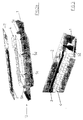
- Figures 2a, 2b are exploded views of the same system, in two different perspective views, which show the control pad proposed by the present invention;
- Figure 3 is a prospective view of a detail of the above mentioned "touch control" system.
- With reference to the enclosed Figures, the
reference numeral 10 indicates a so-called "touch control" system, including a support 1 fastened to a framework, not shown, a capacitive touch-pad 2, integrating a first unit for generating electric signals, not shown, a process andcontrol unit 3, apower group 4 and a self-leveling system 5. - The self-
leveling system 5 includes a plurality ofsupport pins pad 2. - The support pins include e.g. a casing, containing at least one spring.
- A cook top, e.g. of ceramic glass, not shown, carries a plurality of marks, generally defining boxes and the like.
- The upper part of the capacitive touch-
pad 2 adheres to the cook top and its lower part includes the above mentioned first unit and process andcontrol unit 3, connected electrically. - The
power group 4 is fastened to the support 1 and connected electrically, in known and not shown way, to the process andcontrol unit 3 and to a plurality of electric heating elements, not shown, since known. - Now the operation of the cook top control pad proposed by the present invention will be described.
- As it has been specified, the cook top has a plurality of marks depicting a certain number of boxes, which represent, in equivalent terms, push-buttons, which are activated, when touched by the user.
- The activation of a touch-button generates, in the first unit, a corresponding electric signal, which is sent to the process and
control unit 3 to be processed according to a prefixed calculation algorithm. - The computation program determines the generation of second signals, which leave the process and
control unit 3 and adjust the flow of current circulating through the electric heating elements by thepower group 4. - The capacitive touch-
pad 2 allows to distinguish the user's action from the contact or placing of an object of any shape over a touch-button; precisely, each box defines a dielectric and an armature, which are portions of the cook top and of the upper surface of the touch-pad 2, respectively. - A finger touching the area included in this box forms a ground conductor, changing the so defined capacity.
- This change is transformed in an electric signal by the first unit, as stated before.
- In this way, it is possible to place a plurality of displays on the touch-
pad 2, visible to the user through the ceramic glass, which allow setting, through the above mentioned touch-buttons, a clock, if included, a timer and the temperature, which one or more heating elements must reach. - Therefore, the capacitive touch-
pad 2 integrates the whole hardware and software parts, which generate first signals representing operation of a button, distinguish significant signals from non- significant ones, and define second signals, which control thepower group 4 and thus adjust the electric heating elements. - Consequently, the control pad, including, as already said in the introductory note, the touch-pad and the process and control unit, is an exclusive support, which carries the capacitive touch-
pad 2, as well as the process andcontrol unit 3. - All this is obtained with a considerable decrease of the dimensions with respect to known solutions, which results directly in reduction of the production costs.
- The self-
leveling system 5, applied to the capacitive touch-pad 2, allows a complete adherence of the upper surface of the capacitive touch-pad 2 to the cook top, also when the latter is bended, in time or due to an erroneous mounting, which causes a bigger or smaller concavity. - This is obtained by the elastic deformation, which the
support pins leveling system 5, can assume. - The
support pins - Consequently, in case of the cook top deformation, the self-leveling system will keep constant the adherence of the touch-
pad 2, due to the elastic yielding of each support pin. - Anyway, the elastic force performed by each support pin is such, as not to put at risk the integrity of the touch-
pad 2 in any way. - An advantage of the present invention lies in the fact that it proposes a cook top control pad of minimum dimensions, smaller than known control pads, which results in a considerable reduction of production costs.
- Another advantage of the present invention lies in the fact that it proposes a cook top control pad, which is simple to assemble and which can maintain, in time, a constant adherence to the cook top also when the latter bends to a bigger or smaller extent, maintaining intact its functionality.
Claims (5)
- Cook top control pad, of the type including a capacitive touch-pad (2), whose thickness is limited with respect to its other dimensions, and which is associated to a framework, with the upper part of the touch-pad (2) touching a related cook top, and the lower part thereof provided with a first unit for generating first electric signals, resulting from placing at least one hand finger of a user in prefixed areas of the upper surface of said cook top; a process and control unit (3), connected electrically to said first unit, which receives from the latter said first signals, which processes them, and which supplies second signals, depending on the first ones, for controlling a power group (4) for supplying electric heating elements, characterized in that said process and control unit (3) is situated in the lower side of said capacitive touch-pad (2).
- Pad, as claimed in claim 1, characterized in that it includes a self-leveling system (5), which has one side fastened to said framework and the other side supporting said capacitive touch-pad (2).
- Pad, as claimed in claim 2, characterized in that said self-leveling system (5) includes a plurality of support pins having a selected elastic yielding.
- Pad, as claimed in claim 3, characterized in that said support pins are oriented vertically.
- Pad, as claimed in claim 3, characterized in that each of said support pins includes a casing, containing at least one spring.
Applications Claiming Priority (1)
| Application Number | Priority Date | Filing Date | Title |
|---|---|---|---|
| IT000077U ITBO20040077U1 (en) | 2004-09-22 | 2004-09-22 | OPERATING PANEL FOR COOKING HOBS |
Publications (3)
| Publication Number | Publication Date |
|---|---|
| EP1641122A2 true EP1641122A2 (en) | 2006-03-29 |
| EP1641122A3 EP1641122A3 (en) | 2007-04-25 |
| EP1641122B1 EP1641122B1 (en) | 2009-08-05 |
Family
ID=35502495
Family Applications (1)
| Application Number | Title | Priority Date | Filing Date |
|---|---|---|---|
| EP05020546A Revoked EP1641122B1 (en) | 2004-09-22 | 2005-09-21 | Cook top control pad |
Country Status (5)
| Country | Link |
|---|---|
| EP (1) | EP1641122B1 (en) |
| AT (1) | ATE438955T1 (en) |
| DE (1) | DE602005015800D1 (en) |
| ES (1) | ES2330855T3 (en) |
| IT (1) | ITBO20040077U1 (en) |
Cited By (3)
| Publication number | Priority date | Publication date | Assignee | Title |
|---|---|---|---|---|
| DE102007054778A1 (en) * | 2007-11-16 | 2009-05-20 | Diehl Ako Stiftung & Co. Kg | Operating device with at least one pressure switch |
| EP2068085A2 (en) * | 2007-12-04 | 2009-06-10 | Gorenje Gospodinjski aparati d.d. | Electronic control unit for household appliances, in particular for cooking ranges and ovens |
| DE102008062216A1 (en) * | 2008-12-13 | 2010-06-17 | Diehl Ako Stiftung & Co. Kg | Operating device with at least one pressure switch |
Families Citing this family (1)
| Publication number | Priority date | Publication date | Assignee | Title |
|---|---|---|---|---|
| ES2531302B1 (en) * | 2013-09-11 | 2015-12-22 | Bsh Electrodomésticos España, S.A. | Home appliance device for fixing a control unit and home appliance with said device |
Citations (4)
| Publication number | Priority date | Publication date | Assignee | Title |
|---|---|---|---|---|
| EP0443924A1 (en) * | 1990-02-19 | 1991-08-28 | Société SCHOLTES | Means for controlling the heat sources of a cooking appliance by sensory buttons |
| US5867111A (en) * | 1993-03-29 | 1999-02-02 | Donnelly Technology, Inc. | Touch control system |
| DE19817195C1 (en) * | 1998-04-17 | 1999-09-09 | Bosch Siemens Hausgeraete | Ceramic cooking hob with touch-control operation |
| EP1273851A2 (en) * | 2001-07-07 | 2003-01-08 | Therma Grossküchen Produktion AG | Control device for cooking appliance |
-
2004
- 2004-09-22 IT IT000077U patent/ITBO20040077U1/en unknown
-
2005
- 2005-09-21 ES ES05020546T patent/ES2330855T3/en active Active
- 2005-09-21 EP EP05020546A patent/EP1641122B1/en not_active Revoked
- 2005-09-21 AT AT05020546T patent/ATE438955T1/en not_active IP Right Cessation
- 2005-09-21 DE DE602005015800T patent/DE602005015800D1/en not_active Revoked
Patent Citations (4)
| Publication number | Priority date | Publication date | Assignee | Title |
|---|---|---|---|---|
| EP0443924A1 (en) * | 1990-02-19 | 1991-08-28 | Société SCHOLTES | Means for controlling the heat sources of a cooking appliance by sensory buttons |
| US5867111A (en) * | 1993-03-29 | 1999-02-02 | Donnelly Technology, Inc. | Touch control system |
| DE19817195C1 (en) * | 1998-04-17 | 1999-09-09 | Bosch Siemens Hausgeraete | Ceramic cooking hob with touch-control operation |
| EP1273851A2 (en) * | 2001-07-07 | 2003-01-08 | Therma Grossküchen Produktion AG | Control device for cooking appliance |
Cited By (4)
| Publication number | Priority date | Publication date | Assignee | Title |
|---|---|---|---|---|
| DE102007054778A1 (en) * | 2007-11-16 | 2009-05-20 | Diehl Ako Stiftung & Co. Kg | Operating device with at least one pressure switch |
| EP2068085A2 (en) * | 2007-12-04 | 2009-06-10 | Gorenje Gospodinjski aparati d.d. | Electronic control unit for household appliances, in particular for cooking ranges and ovens |
| DE102008062216A1 (en) * | 2008-12-13 | 2010-06-17 | Diehl Ako Stiftung & Co. Kg | Operating device with at least one pressure switch |
| DE102008062216B4 (en) * | 2008-12-13 | 2010-09-23 | Diehl Ako Stiftung & Co. Kg | Operating device with at least one pressure switch |
Also Published As
| Publication number | Publication date |
|---|---|
| ES2330855T3 (en) | 2009-12-16 |
| ITBO20040077U1 (en) | 2004-12-22 |
| EP1641122A3 (en) | 2007-04-25 |
| ATE438955T1 (en) | 2009-08-15 |
| DE602005015800D1 (en) | 2009-09-17 |
| EP1641122B1 (en) | 2009-08-05 |
Similar Documents
| Publication | Publication Date | Title |
|---|---|---|
| US6492978B1 (en) | Keyscreen | |
| US10452166B2 (en) | Touch device and method for performing fingerprint detection on touch device | |
| US7786400B2 (en) | Operating device with an operating field and a sensor element for an electrical appliance and method for operating the operating device | |
| US20060181515A1 (en) | Transaction terminal and adaptor therefor | |
| AU2014380483B2 (en) | Fingerprint recognition device, manufacturing method therefor and electronic device | |
| US20070285872A1 (en) | Capacitive switch of electric/electronic device | |
| EP1641122B1 (en) | Cook top control pad | |
| CN104049803A (en) | Mobile terminal | |
| KR20150105999A (en) | Electronic gaming and/or entertainment device | |
| CN105787328A (en) | Method for increasing unlocking speed and mobile terminal | |
| WO2003088202A1 (en) | Symbol encoding apparatus and method | |
| WO2007009251A1 (en) | Illuminated touch control interface | |
| WO2016192641A1 (en) | Key device manipulation and control method, key device and terminal | |
| US10697645B2 (en) | Cooking apparatus and touch sensor assembly for cooking apparatus | |
| US20100039375A1 (en) | Signal Processing Method of Multi-Finger Touch Supported Touch Apparatus having Hidden Physical Button | |
| JP3741667B2 (en) | Cooker | |
| CN114631672A (en) | Intelligent ring and control method thereof | |
| JP2014041441A (en) | Device and method of back face tactile information presentation type information input | |
| EP2911300A1 (en) | Touch sensitive electrical control device with a haptic feedback | |
| KR101357797B1 (en) | Super slim touch keyboard | |
| JP2002203211A (en) | Card reader | |
| US20150185863A1 (en) | Entry device and paper sheets handling device | |
| CN107113942B (en) | Switch controlling device | |
| CN112817224A (en) | Wearable device | |
| CN109419320B (en) | Rice cooker |
Legal Events
| Date | Code | Title | Description |
|---|---|---|---|
| PUAI | Public reference made under article 153(3) epc to a published international application that has entered the european phase |
Free format text: ORIGINAL CODE: 0009012 |
|
| AK | Designated contracting states |
Kind code of ref document: A2 Designated state(s): AT BE BG CH CY CZ DE DK EE ES FI FR GB GR HU IE IS IT LI LT LU LV MC NL PL PT RO SE SI SK TR |
|
| AX | Request for extension of the european patent |
Extension state: AL BA HR MK YU |
|
| PUAL | Search report despatched |
Free format text: ORIGINAL CODE: 0009013 |
|
| AK | Designated contracting states |
Kind code of ref document: A3 Designated state(s): AT BE BG CH CY CZ DE DK EE ES FI FR GB GR HU IE IS IT LI LT LU LV MC NL PL PT RO SE SI SK TR |
|
| AX | Request for extension of the european patent |
Extension state: AL BA HR MK YU |
|
| 17P | Request for examination filed |
Effective date: 20071018 |
|
| 17Q | First examination report despatched |
Effective date: 20071115 |
|
| AKX | Designation fees paid |
Designated state(s): AT BE BG CH CY CZ DE DK EE ES FI FR GB GR HU IE IS IT LI LT LU LV MC NL PL PT RO SE SI SK TR |
|
| GRAP | Despatch of communication of intention to grant a patent |
Free format text: ORIGINAL CODE: EPIDOSNIGR1 |
|
| GRAS | Grant fee paid |
Free format text: ORIGINAL CODE: EPIDOSNIGR3 |
|
| GRAA | (expected) grant |
Free format text: ORIGINAL CODE: 0009210 |
|
| AK | Designated contracting states |
Kind code of ref document: B1 Designated state(s): AT BE BG CH CY CZ DE DK EE ES FI FR GB GR HU IE IS IT LI LT LU LV MC NL PL PT RO SE SI SK TR |
|
| REG | Reference to a national code |
Ref country code: GB Ref legal event code: FG4D |
|
| REG | Reference to a national code |
Ref country code: CH Ref legal event code: EP |
|
| REG | Reference to a national code |
Ref country code: IE Ref legal event code: FG4D |
|
| REF | Corresponds to: |
Ref document number: 602005015800 Country of ref document: DE Date of ref document: 20090917 Kind code of ref document: P |
|
| REG | Reference to a national code |
Ref country code: ES Ref legal event code: FG2A Ref document number: 2330855 Country of ref document: ES Kind code of ref document: T3 |
|
| LTIE | Lt: invalidation of european patent or patent extension |
Effective date: 20090805 |
|
| PG25 | Lapsed in a contracting state [announced via postgrant information from national office to epo] |
Ref country code: SE Free format text: LAPSE BECAUSE OF FAILURE TO SUBMIT A TRANSLATION OF THE DESCRIPTION OR TO PAY THE FEE WITHIN THE PRESCRIBED TIME-LIMIT Effective date: 20090805 Ref country code: AT Free format text: LAPSE BECAUSE OF FAILURE TO SUBMIT A TRANSLATION OF THE DESCRIPTION OR TO PAY THE FEE WITHIN THE PRESCRIBED TIME-LIMIT Effective date: 20090805 Ref country code: FI Free format text: LAPSE BECAUSE OF FAILURE TO SUBMIT A TRANSLATION OF THE DESCRIPTION OR TO PAY THE FEE WITHIN THE PRESCRIBED TIME-LIMIT Effective date: 20090805 Ref country code: IS Free format text: LAPSE BECAUSE OF FAILURE TO SUBMIT A TRANSLATION OF THE DESCRIPTION OR TO PAY THE FEE WITHIN THE PRESCRIBED TIME-LIMIT Effective date: 20091205 Ref country code: LT Free format text: LAPSE BECAUSE OF FAILURE TO SUBMIT A TRANSLATION OF THE DESCRIPTION OR TO PAY THE FEE WITHIN THE PRESCRIBED TIME-LIMIT Effective date: 20090805 |
|
| NLV1 | Nl: lapsed or annulled due to failure to fulfill the requirements of art. 29p and 29m of the patents act | ||
| PG25 | Lapsed in a contracting state [announced via postgrant information from national office to epo] |
Ref country code: NL Free format text: LAPSE BECAUSE OF FAILURE TO SUBMIT A TRANSLATION OF THE DESCRIPTION OR TO PAY THE FEE WITHIN THE PRESCRIBED TIME-LIMIT Effective date: 20090805 Ref country code: LV Free format text: LAPSE BECAUSE OF FAILURE TO SUBMIT A TRANSLATION OF THE DESCRIPTION OR TO PAY THE FEE WITHIN THE PRESCRIBED TIME-LIMIT Effective date: 20090805 Ref country code: PL Free format text: LAPSE BECAUSE OF FAILURE TO SUBMIT A TRANSLATION OF THE DESCRIPTION OR TO PAY THE FEE WITHIN THE PRESCRIBED TIME-LIMIT Effective date: 20090805 Ref country code: SI Free format text: LAPSE BECAUSE OF FAILURE TO SUBMIT A TRANSLATION OF THE DESCRIPTION OR TO PAY THE FEE WITHIN THE PRESCRIBED TIME-LIMIT Effective date: 20090805 |
|
| PG25 | Lapsed in a contracting state [announced via postgrant information from national office to epo] |
Ref country code: PT Free format text: LAPSE BECAUSE OF FAILURE TO SUBMIT A TRANSLATION OF THE DESCRIPTION OR TO PAY THE FEE WITHIN THE PRESCRIBED TIME-LIMIT Effective date: 20091205 Ref country code: BG Free format text: LAPSE BECAUSE OF FAILURE TO SUBMIT A TRANSLATION OF THE DESCRIPTION OR TO PAY THE FEE WITHIN THE PRESCRIBED TIME-LIMIT Effective date: 20091105 |
|
| PG25 | Lapsed in a contracting state [announced via postgrant information from national office to epo] |
Ref country code: DK Free format text: LAPSE BECAUSE OF FAILURE TO SUBMIT A TRANSLATION OF THE DESCRIPTION OR TO PAY THE FEE WITHIN THE PRESCRIBED TIME-LIMIT Effective date: 20090805 Ref country code: RO Free format text: LAPSE BECAUSE OF FAILURE TO SUBMIT A TRANSLATION OF THE DESCRIPTION OR TO PAY THE FEE WITHIN THE PRESCRIBED TIME-LIMIT Effective date: 20090805 Ref country code: MC Free format text: LAPSE BECAUSE OF NON-PAYMENT OF DUE FEES Effective date: 20090930 Ref country code: EE Free format text: LAPSE BECAUSE OF FAILURE TO SUBMIT A TRANSLATION OF THE DESCRIPTION OR TO PAY THE FEE WITHIN THE PRESCRIBED TIME-LIMIT Effective date: 20090805 Ref country code: CZ Free format text: LAPSE BECAUSE OF FAILURE TO SUBMIT A TRANSLATION OF THE DESCRIPTION OR TO PAY THE FEE WITHIN THE PRESCRIBED TIME-LIMIT Effective date: 20090805 |
|
| REG | Reference to a national code |
Ref country code: CH Ref legal event code: PL |
|
| PLBI | Opposition filed |
Free format text: ORIGINAL CODE: 0009260 |
|
| PG25 | Lapsed in a contracting state [announced via postgrant information from national office to epo] |
Ref country code: SK Free format text: LAPSE BECAUSE OF FAILURE TO SUBMIT A TRANSLATION OF THE DESCRIPTION OR TO PAY THE FEE WITHIN THE PRESCRIBED TIME-LIMIT Effective date: 20090805 |
|
| PLAX | Notice of opposition and request to file observation + time limit sent |
Free format text: ORIGINAL CODE: EPIDOSNOBS2 |
|
| 26 | Opposition filed |
Opponent name: AEG HAUSGERAETE GMBH Effective date: 20100430 |
|
| PG25 | Lapsed in a contracting state [announced via postgrant information from national office to epo] |
Ref country code: BE Free format text: LAPSE BECAUSE OF FAILURE TO SUBMIT A TRANSLATION OF THE DESCRIPTION OR TO PAY THE FEE WITHIN THE PRESCRIBED TIME-LIMIT Effective date: 20090805 |
|
| PG25 | Lapsed in a contracting state [announced via postgrant information from national office to epo] |
Ref country code: IE Free format text: LAPSE BECAUSE OF NON-PAYMENT OF DUE FEES Effective date: 20090921 |
|
| PLAF | Information modified related to communication of a notice of opposition and request to file observations + time limit |
Free format text: ORIGINAL CODE: EPIDOSCOBS2 |
|
| PG25 | Lapsed in a contracting state [announced via postgrant information from national office to epo] |
Ref country code: LI Free format text: LAPSE BECAUSE OF NON-PAYMENT OF DUE FEES Effective date: 20090930 Ref country code: CH Free format text: LAPSE BECAUSE OF NON-PAYMENT OF DUE FEES Effective date: 20090930 Ref country code: GR Free format text: LAPSE BECAUSE OF FAILURE TO SUBMIT A TRANSLATION OF THE DESCRIPTION OR TO PAY THE FEE WITHIN THE PRESCRIBED TIME-LIMIT Effective date: 20091106 |
|
| RDAF | Communication despatched that patent is revoked |
Free format text: ORIGINAL CODE: EPIDOSNREV1 |
|
| PGFP | Annual fee paid to national office [announced via postgrant information from national office to epo] |
Ref country code: IT Payment date: 20100923 Year of fee payment: 6 |
|
| PGFP | Annual fee paid to national office [announced via postgrant information from national office to epo] |
Ref country code: GB Payment date: 20100923 Year of fee payment: 6 |
|
| PGFP | Annual fee paid to national office [announced via postgrant information from national office to epo] |
Ref country code: FR Payment date: 20101008 Year of fee payment: 6 |
|
| RDAG | Patent revoked |
Free format text: ORIGINAL CODE: 0009271 |
|
| STAA | Information on the status of an ep patent application or granted ep patent |
Free format text: STATUS: PATENT REVOKED |
|
| PGFP | Annual fee paid to national office [announced via postgrant information from national office to epo] |
Ref country code: DE Payment date: 20100924 Year of fee payment: 6 |
|
| 27W | Patent revoked |
Effective date: 20101113 |
|
| GBPR | Gb: patent revoked under art. 102 of the ep convention designating the uk as contracting state |
Effective date: 20101113 |
|
| PG25 | Lapsed in a contracting state [announced via postgrant information from national office to epo] |
Ref country code: LU Free format text: LAPSE BECAUSE OF NON-PAYMENT OF DUE FEES Effective date: 20090921 |
|
| PG25 | Lapsed in a contracting state [announced via postgrant information from national office to epo] |
Ref country code: HU Free format text: LAPSE BECAUSE OF FAILURE TO SUBMIT A TRANSLATION OF THE DESCRIPTION OR TO PAY THE FEE WITHIN THE PRESCRIBED TIME-LIMIT Effective date: 20100206 |
|
| PGFP | Annual fee paid to national office [announced via postgrant information from national office to epo] |
Ref country code: ES Payment date: 20100924 Year of fee payment: 6 |
|
| PG25 | Lapsed in a contracting state [announced via postgrant information from national office to epo] |
Ref country code: TR Free format text: LAPSE BECAUSE OF FAILURE TO SUBMIT A TRANSLATION OF THE DESCRIPTION OR TO PAY THE FEE WITHIN THE PRESCRIBED TIME-LIMIT Effective date: 20090805 |
|
| PG25 | Lapsed in a contracting state [announced via postgrant information from national office to epo] |
Ref country code: CY Free format text: LAPSE BECAUSE OF FAILURE TO SUBMIT A TRANSLATION OF THE DESCRIPTION OR TO PAY THE FEE WITHIN THE PRESCRIBED TIME-LIMIT Effective date: 20090805 |