EP1666905A2 - Electric tightening device - Google Patents
Electric tightening device Download PDFInfo
- Publication number
- EP1666905A2 EP1666905A2 EP05025794A EP05025794A EP1666905A2 EP 1666905 A2 EP1666905 A2 EP 1666905A2 EP 05025794 A EP05025794 A EP 05025794A EP 05025794 A EP05025794 A EP 05025794A EP 1666905 A2 EP1666905 A2 EP 1666905A2
- Authority
- EP
- European Patent Office
- Prior art keywords
- motor
- current
- power source
- voltage
- threshold value
- Prior art date
- Legal status (The legal status is an assumption and is not a legal conclusion. Google has not performed a legal analysis and makes no representation as to the accuracy of the status listed.)
- Granted
Links
- 230000007423 decrease Effects 0.000 claims abstract description 11
- 230000007257 malfunction Effects 0.000 description 6
- 238000006243 chemical reaction Methods 0.000 description 4
- 230000007246 mechanism Effects 0.000 description 3
- 238000000034 method Methods 0.000 description 3
- 229910000831 Steel Inorganic materials 0.000 description 2
- 238000010586 diagram Methods 0.000 description 2
- 238000005070 sampling Methods 0.000 description 2
- 239000010959 steel Substances 0.000 description 2
- 230000008859 change Effects 0.000 description 1
- 238000007796 conventional method Methods 0.000 description 1
- 230000008878 coupling Effects 0.000 description 1
- 238000010168 coupling process Methods 0.000 description 1
- 238000005859 coupling reaction Methods 0.000 description 1
- 238000002474 experimental method Methods 0.000 description 1
- 230000008569 process Effects 0.000 description 1
- 230000009467 reduction Effects 0.000 description 1
Images


Classifications
-
- G—PHYSICS
- G01—MEASURING; TESTING
- G01R—MEASURING ELECTRIC VARIABLES; MEASURING MAGNETIC VARIABLES
- G01R19/00—Arrangements for measuring currents or voltages or for indicating presence or sign thereof
- G01R19/165—Indicating that current or voltage is either above or below a predetermined value or within or outside a predetermined range of values
- G01R19/16533—Indicating that current or voltage is either above or below a predetermined value or within or outside a predetermined range of values characterised by the application
- G01R19/16538—Indicating that current or voltage is either above or below a predetermined value or within or outside a predetermined range of values characterised by the application in AC or DC supplies
- G01R19/16542—Indicating that current or voltage is either above or below a predetermined value or within or outside a predetermined range of values characterised by the application in AC or DC supplies for batteries
-
- B—PERFORMING OPERATIONS; TRANSPORTING
- B25—HAND TOOLS; PORTABLE POWER-DRIVEN TOOLS; MANIPULATORS
- B25B—TOOLS OR BENCH DEVICES NOT OTHERWISE PROVIDED FOR, FOR FASTENING, CONNECTING, DISENGAGING OR HOLDING
- B25B21/00—Portable power-driven screw or nut setting or loosening tools; Attachments for drilling apparatus serving the same purpose
-
- B—PERFORMING OPERATIONS; TRANSPORTING
- B25—HAND TOOLS; PORTABLE POWER-DRIVEN TOOLS; MANIPULATORS
- B25B—TOOLS OR BENCH DEVICES NOT OTHERWISE PROVIDED FOR, FOR FASTENING, CONNECTING, DISENGAGING OR HOLDING
- B25B23/00—Details of, or accessories for, spanners, wrenches, screwdrivers
-
- B—PERFORMING OPERATIONS; TRANSPORTING
- B25—HAND TOOLS; PORTABLE POWER-DRIVEN TOOLS; MANIPULATORS
- B25B—TOOLS OR BENCH DEVICES NOT OTHERWISE PROVIDED FOR, FOR FASTENING, CONNECTING, DISENGAGING OR HOLDING
- B25B23/00—Details of, or accessories for, spanners, wrenches, screwdrivers
- B25B23/14—Arrangement of torque limiters or torque indicators in wrenches or screwdrivers
- B25B23/147—Arrangement of torque limiters or torque indicators in wrenches or screwdrivers specially adapted for electrically operated wrenches or screwdrivers
-
- G—PHYSICS
- G01—MEASURING; TESTING
- G01R—MEASURING ELECTRIC VARIABLES; MEASURING MAGNETIC VARIABLES
- G01R31/00—Arrangements for testing electric properties; Arrangements for locating electric faults; Arrangements for electrical testing characterised by what is being tested not provided for elsewhere
- G01R31/36—Arrangements for testing, measuring or monitoring the electrical condition of accumulators or electric batteries, e.g. capacity or state of charge [SoC]
- G01R31/3644—Constructional arrangements
- G01R31/3648—Constructional arrangements comprising digital calculation means, e.g. for performing an algorithm
-
- G—PHYSICS
- G01—MEASURING; TESTING
- G01R—MEASURING ELECTRIC VARIABLES; MEASURING MAGNETIC VARIABLES
- G01R31/00—Arrangements for testing electric properties; Arrangements for locating electric faults; Arrangements for electrical testing characterised by what is being tested not provided for elsewhere
- G01R31/36—Arrangements for testing, measuring or monitoring the electrical condition of accumulators or electric batteries, e.g. capacity or state of charge [SoC]
- G01R31/382—Arrangements for monitoring battery or accumulator variables, e.g. SoC
- G01R31/3828—Arrangements for monitoring battery or accumulator variables, e.g. SoC using current integration
-
- G—PHYSICS
- G01—MEASURING; TESTING
- G01R—MEASURING ELECTRIC VARIABLES; MEASURING MAGNETIC VARIABLES
- G01R31/00—Arrangements for testing electric properties; Arrangements for locating electric faults; Arrangements for electrical testing characterised by what is being tested not provided for elsewhere
- G01R31/36—Arrangements for testing, measuring or monitoring the electrical condition of accumulators or electric batteries, e.g. capacity or state of charge [SoC]
- G01R31/382—Arrangements for monitoring battery or accumulator variables, e.g. SoC
- G01R31/3842—Arrangements for monitoring battery or accumulator variables, e.g. SoC combining voltage and current measurements
-
- G—PHYSICS
- G01—MEASURING; TESTING
- G01R—MEASURING ELECTRIC VARIABLES; MEASURING MAGNETIC VARIABLES
- G01R31/00—Arrangements for testing electric properties; Arrangements for locating electric faults; Arrangements for electrical testing characterised by what is being tested not provided for elsewhere
- G01R31/40—Testing power supplies
-
- Y—GENERAL TAGGING OF NEW TECHNOLOGICAL DEVELOPMENTS; GENERAL TAGGING OF CROSS-SECTIONAL TECHNOLOGIES SPANNING OVER SEVERAL SECTIONS OF THE IPC; TECHNICAL SUBJECTS COVERED BY FORMER USPC CROSS-REFERENCE ART COLLECTIONS [XRACs] AND DIGESTS
- Y10—TECHNICAL SUBJECTS COVERED BY FORMER USPC
- Y10S—TECHNICAL SUBJECTS COVERED BY FORMER USPC CROSS-REFERENCE ART COLLECTIONS [XRACs] AND DIGESTS
- Y10S388/00—Electricity: motor control systems
- Y10S388/935—Specific application:
- Y10S388/937—Hand tool
Definitions
- the present invention relates to an electric tightening device for tightening abolt to a member as an object of tightening such as a steel frame.
- FIG. 7 is a side view showing bolts 90 and nuts 9 for building or bridge temporarily attached in a plurality of positions in a member 91 as an object of tightening such as a steel frame and a conventional electric tightening device 8 for tightening the nuts 9 to the bolts 90 one by one (refer to Japanese Patent Laid-Open No. 2000-117649).
- the electric tightening device 8 is constructed by housing a motor M and a planetary gear mechanism 82 including a reduction gear in a tightening device body 80 and coupling an outer socket 7 to the tip of the tightening device body 80.
- a handle 81 of the tightening device body 80 is provided with a switch SW for starting/stopping operation.
- the outer socket 7 integrally has a projected reaction force receiving arm 70 on its outer periphery and has therein an inner socket 6 which engages with the nut 9 and rotates the nut 9.
- the rotary shaft of the motor M is coupled to a center gear (sun gear)
- the inner socket 6 is coupled to a plurality of planetary gears engaged with the center gear
- the outer socket 7 is coupled to a revolution gear engaged with the planetary gears.
- Electric power is fed to the motor M from a battery (not shown) as a power source.
- a battery not shown
- the power source is not limited to a battery but may be a DC or AC power source from the outside. In the following, the case where a battery is used as a power source will be described. In the case of the AC power source, "shortage of the residual quantity of the battery” corresponds to "insufficient capacity of the AC power source or an electric circuit".
- a voltage drop of the battery terminal voltage upon start of the motor M is larger than that in a less-deteriorated battery.
- An object of the present invention is to accurately notify the operator of whether a nut can be tightened or not with a simple configuration that does not include the battery temperature measuring means, a data table, and the like.
- a controller 1 compares a minimum value of a power source voltage generated on start of a motor M with a threshold value in a storing unit 10 and, when the minimum value is less than the threshold value, notifies of shortage of the power source terminal voltage.
- the controller 1 compares a maximum value of starting current generated on start of the motor M with a threshold value in the storing unit 10 and, when the maximum value is less than the threshold value, notifies of shortage of the power source terminal voltage.
- the controller 1 compares a value obtained by integrating a power source voltage which decreases in association with starting current generated on start of the motor M for only predetermined time with the threshold value in the storing unit 10 and, when the integral value is less than the threshold value, notifies of shortage of the power source terminal voltage.
- the controller 1 compares a value obtained by integrating starting current generated on start of the motor M for only predetermined value with the threshold value in the storing unit 10 and, when the integral value is less than the threshold value, notifies of shortage of the power source terminal voltage.
- FIG. 1 is an internal block diagram of the electric tightening device 8 of the embodiment.
- the motor M is rotated by a motor drive circuit 5.
- a battery terminal voltage sensor 3 for detecting a terminal voltage of the battery 2
- a circuit current sensor 4 for detecting a circuit current Ic are provided.
- Signals from the sensors 3 and 4 are input to a controller 1.
- the controller 1 receives the signals from the sensors 3 and 4 and controls the motor drive circuit 5.
- a torque setting dial 12 operated by the operator at the time of setting a tightening torque is connected.
- the controller 1 stops the operation of the motor M.
- the controller 1 is connected to a storing unit 10 as a memory in which a threshold value of the battery terminal voltage is stored and a display unit 11 constructed by a group of various lamps.
- the lamp group is constructed by, concretely, an "operation lamp” indicating that the motor is operating, a “tightening lamp” indicating that the nut 9 is being tightened, a “tightening completion lamp” indicative of completion of tightening of the nut 9, and a “residual quantity shortage lamp” notifying of shortage in the battery residual quantity.
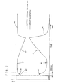
- FIG. 2 is a graph whose vertical axis indicates the battery terminal voltage Vs detected by the battery terminal voltage sensor 3 and the circuit current Ic detected by the circuit current sensor 4 and whose horizontal axis indicates elapsed time, and showing changes in the battery terminal voltage Vs and the circuit current Ic when normal tightening operation is performed.
- the revolution speed (not shown) of the motor M increases with lapse of time of hundreds milliseconds and converges to no-load speed.
- the circuit current Ic decreases synchronously with convergence of the revolution speed and converges to a current value indicated by a portion B1.
- the battery terminal voltage rises and converges to a voltage value indicated by a portion B2.
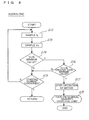
- FIG. 3 shows a control flowchart of an electric tightening device.
- the motor M can start when the battery terminal voltage Vs is 12 V or higher as a first threshold value and, further, tightening can be performed at 10 V or higher as a second threshold value.
- the first and second thresholds are not limited to the values.
- the controller 1 samples the battery terminal voltage Vs before the motor M is energized and started via the battery terminal voltage sensor 3 (S1) and compares the battery terminal voltage Vs with the first threshold value 12V stored in the storing unit 10 (S2). When the value from the battery terminal voltage sensor 3 is less than the first threshold value, the controller 1 determines that the motor M cannot be started, turns on the "residual quantity shortage lamp" in the display unit 11 (S11), and finishes the control without passing current to the motor M.
- the controller 1 starts passing current to the motor M (S3), turns on the "operation lamp” (S4), performs operation based on the subroutine of FIG. 4 (S5), and detects starting current generated immediately after the motor M starts.
- the controller 1 samples the circuit current Ic values (S12) and determines whether the starting current has converged or not (S15).
- the controller 1 samples the battery terminal voltage Vs values while the starting current converges (S13).
- the controller 1 compares the voltage at the point A3 with 10 V as the second threshold value stored in the storing unit 10 (S16).
- the controller 1 determines that normal tightening is impossible, stops passage of current to the motor M (S17), turns on the "residual quantity shortage lamp" in the display unit 11 (S18), and finishes the control.
- the controller 1 determines that normal tightening can be performed, confirms convergence of the starting current, and returns to step S5.
- the controller 1 monitors the circuit current Ic and detects the load current accompanying the tightening of the nut 9 (S6), the controller 1 turns on the "tightening lamp” (S7).
- the controller 1 stops operation of the motor M (S9), turns on the "tightening completion lamp” (S10), and completes the tightening of the nut 9.
- the starting current of the motor M is detected, the minimum value of the battery terminal voltage Vs accompanying generation of the starting current is obtained, the minimum value is compared with the threshold value in the storing unit 10, and whether the operation of the motor M can be continued or not is determined.
- the threshold value of the starting current is pre-stored in the storing unit 10. It is also possible to detect the battery terminal voltage Vs, obtain the minimum value of the battery terminal voltage Vs when the motor M is started, obtain the maximum value of the starting current when the voltage minimum value is detected, and compare the current maximum value with the threshold value, thereby determining whether the operation of the motor M can be continued or not. That is, when the current maximum value is less than the threshold value, it is determined that the operation of the motor M cannot be continued. When the current maximum value is equal to or larger than the threshold value, the operation of the motor M is continued.
- the threshold value of the starting current is pre-stored in the storing unit 10. It is also possible to detect only the starting current, obtain the maximum value of the starting current, and compare the maximum value with the threshold value in the storing unit 10, thereby determining whether the operation of the motor M can be continued or not.
- a value obtained by integrating the battery terminal voltage only for predetermined time in place of the decrease amount of the battery terminal voltage upon start of the motor is determined. The operation will be described by using the flowcharts of FIGS. 5 and 6.
- a value obtained by integrating terminal voltages of the power source is stored as a threshold value for the integral value.
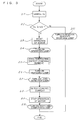
- the general operation in the second embodiment is shown in the flowchart of FIG. 5.
- the second embodiment is characterized by the subroutine of FIG. 6. Therefore, the operations in steps S19 to S22 and step S29 in the flowchart of FIG. 5 are the same as those in steps S1 to S4 and step S11 in the flowchart of FIG. 3, so that the detailed description will not be repeated.
- the operation performed at the time of detecting the starting current in step S23 will be described by using the subroutine of FIG. 6.
- the controller 1 samples the circuit current Ic values (S30) and determines whether the starting current has converged or not (S33).
- the controller 1 also samples the battery terminal voltage Vs values during convergence of the starting current (S31).
- the circuit current Ic and the battery terminal voltage Vs value are sampled every 10 msec.
- the controller 1 After sampling the battery terminal voltage Vs value, the controller 1 accumulates the battery terminal voltage Vs values sampled for 200 msec to obtain a voltage integral value, and compares the voltage integral value with the integral threshold value stored in the storing unit 10 (S32).
- the controller 1 determines that normal tightening cannot be performed, stops passage of current to the motor M (S34), turns on the "residual quantity shortage lamp" in the display unit 11 (S35), and finishes the control.
- sampling speed of 10 msec and the integral threshold value of 200 msec are examples and the invention is not limited to the values.
- the controller 1 determines that normal tightening can be performed, confirms convergence of starting current (S33), and returns to step S23.
- the operation of the motor M can be continued or not is detected from the value obtained by integrating the battery terminal voltage Vs which decreases in association with the starting current of the motor M. Consequently, there is no possibility that malfunction occurs during operation of the motor M obviously in a battery having an insufficient residual quantity but also in a deteriorated battery having a sufficient residual quantity.
- a simple configuration which does not require a sensor for measuring the temperature of the battery, means for recording the residual quantity of the battery, and the like, whether the nut 9 can be tightened or not can be accurately notified to the operator and the motor M can be stopped in advance.
- the applicant of the present invention has confirmed that the precision in the case of detecting whether the operation of the motor M can be continued or not from the value obtained by integrating the voltage values is higher than that in the case of determining whether the operation of the motor M can be continued or not from the minimum value of the battery terminal voltage upon start of the motor.
- whether the operation of the motor M can be continued or not is detected by comparing the value obtained by integrating the battery terminal voltage Vs which decreases in association with the starting current of the motor M for only predetermined time with the integral threshold value.
- the operation of the motor M is continued.
- the battery may be a primary battery or a secondary battery. Although a lamp is used to notify the operator that the residual quantity of the battery is insufficient, such as a buzzer may be also used.
Abstract
Description
- The present invention relates to an electric tightening device for tightening abolt to a member as an object of tightening such as a steel frame.
- FIG. 7 is a side
view showing bolts 90 andnuts 9 for building or bridge temporarily attached in a plurality of positions in amember 91 as an object of tightening such as a steel frame and a conventionalelectric tightening device 8 for tightening thenuts 9 to thebolts 90 one by one (refer to Japanese Patent Laid-Open No. 2000-117649). Theelectric tightening device 8 is constructed by housing a motor M and aplanetary gear mechanism 82 including a reduction gear in a tighteningdevice body 80 and coupling anouter socket 7 to the tip of the tighteningdevice body 80. Ahandle 81 of the tighteningdevice body 80 is provided with a switch SW for starting/stopping operation. - The
outer socket 7 integrally has a projected reactionforce receiving arm 70 on its outer periphery and has therein an inner socket 6 which engages with thenut 9 and rotates thenut 9. In theplanetary gear mechanism 82, the rotary shaft of the motor M is coupled to a center gear (sun gear), the inner socket 6 is coupled to a plurality of planetary gears engaged with the center gear, and theouter socket 7 is coupled to a revolution gear engaged with the planetary gears. When the inner socket 6 is engaged with thenut 9 and the motor M is rotated by turning on the power source, the reactionforce receiving arm 70 is rotated by theplanetary gear mechanism 82. From the time point when the reactionforce receiving arm 70 comes into contact with the neighboring nut 9a, the inner socket 6 rotates and thenut 9 accordingly rotates, thereby tightening thenut 9. - Electric power is fed to the motor M from a battery (not shown) as a power source. When the residual quantity of the battery is insufficient, it is indicated by a pilot lamp or the like. The power source is not limited to a battery but may be a DC or AC power source from the outside. In the following, the case where a battery is used as a power source will be described. In the case of the AC power source, "shortage of the residual quantity of the battery" corresponds to "insufficient capacity of the AC power source or an electric circuit".
- There are various means for determining whether the residual quantity of the battery is insufficient or not. When the determination is made by detecting only a terminal voltage of a battery before the motor M is started, the following problem occurs.
- Specifically, even when the terminal voltage before the motor M is started is sufficient, for example, in a deteriorated battery, a voltage drop of the battery terminal voltage upon start of the motor M is larger than that in a less-deteriorated battery.
- Therefore, in the deteriorated battery, even if the battery terminal voltage before the motor M is started is a voltage which can start the motor M, when the
nut 9 is tightened and a load increases, the battery terminal voltage largely drops, malfunction occurs during operation of the motor M, and there is the possibility that thenut 9 cannot be tightened properly. - There is another electric tightening device in which battery temperature measuring means, means for storing the residual quantity of a battery and, further, means for entering a discharge efficiency value preliminarily obtained by experiments into a data table and computing an exact battery residual quantity on the basis of a value read from the data table are assembled. However, the electric tightening device has a problem that the cost is too high.
- An object of the present invention is to accurately notify the operator of whether a nut can be tightened or not with a simple configuration that does not include the battery temperature measuring means, a data table, and the like.
- In an electric tightening device of the present invention, a
controller 1 compares a minimum value of a power source voltage generated on start of a motor M with a threshold value in astoring unit 10 and, when the minimum value is less than the threshold value, notifies of shortage of the power source terminal voltage. - Alternately, the
controller 1 compares a maximum value of starting current generated on start of the motor M with a threshold value in thestoring unit 10 and, when the maximum value is less than the threshold value, notifies of shortage of the power source terminal voltage. - Alternately, the
controller 1 compares a value obtained by integrating a power source voltage which decreases in association with starting current generated on start of the motor M for only predetermined time with the threshold value in thestoring unit 10 and, when the integral value is less than the threshold value, notifies of shortage of the power source terminal voltage. - Alternately, the
controller 1 compares a value obtained by integrating starting current generated on start of the motor M for only predetermined value with the threshold value in thestoring unit 10 and, when the integral value is less than the threshold value, notifies of shortage of the power source terminal voltage. - In the present invention, whether operation of the motor M can be continued or not is determined from the minimum value of the power source voltage or the maximum value of the starting current on start of the motor. Consequently, there is no possibility that malfunction occurs in the motor M while tightening the
nut 9, obviously in a battery having an insufficient residual quantity and also in a deteriorated battery having a sufficient residual quantity. With a simple configuration which does not require a sensor for measuring the temperature of the battery, means for recording the residual quantity of the battery, and the like, whether thenut 9 can be tightened or not can be accurately notified to the operator. - Similarly, by determining whether the operation of the motor M can be continued or not on the basis of a value obtained by integrating the power source voltage or starting current only for predetermined time, whether the
nut 9 can be tightened or not can be accurately notified to the operator. -
- FIG. 1 is an internal block diagram of an electric tightening device according to the present invention;
- FIG. 2 is a graph in which the vertical axis shows a battery terminal voltage Vs and a circuit current Ic and the horizontal axis indicates lapsed time;
- FIG. 3 is a flowchart showing operation of a first embodiment of the electric tightening device;
- FIG. 4 is a flowchart showing a subroutine of the flowchart of FIG. 3;
- FIG. 5 is a flowchart showing operation of a second embodiment of the electric tightening device;
- FIG. 6 is a flowchart showing a subroutine of the flowchart of FIG. 5; and
- FIG. 7 is a side view of a conventional electric tightening device.
- An embodiment of the present invention will be described in detail hereinbelow with reference to the drawings.
- The embodiment is similar to the conventional technique with respect to the point that the inner socket 6 and the
outer socket 7 are provided in the tighteningdevice body 80. FIG. 1 is an internal block diagram of theelectric tightening device 8 of the embodiment. The motor M is rotated by amotor drive circuit 5. Between abattery 2 and themotor drive circuit 5, a batteryterminal voltage sensor 3 for detecting a terminal voltage of thebattery 2 and acircuit current sensor 4 for detecting a circuit current Ic are provided. Signals from thesensors controller 1. Thecontroller 1 receives the signals from thesensors motor drive circuit 5. To thecontroller 1, atorque setting dial 12 operated by the operator at the time of setting a tightening torque is connected. When the circuit current Ic reaches a control current value corresponding to a set tightening torque, thecontroller 1 stops the operation of the motor M. - The
controller 1 is connected to astoring unit 10 as a memory in which a threshold value of the battery terminal voltage is stored and adisplay unit 11 constructed by a group of various lamps. The lamp group is constructed by, concretely, an "operation lamp" indicating that the motor is operating, a "tightening lamp" indicating that thenut 9 is being tightened, a "tightening completion lamp" indicative of completion of tightening of thenut 9, and a "residual quantity shortage lamp" notifying of shortage in the battery residual quantity. - FIG. 2 is a graph whose vertical axis indicates the battery terminal voltage Vs detected by the battery
terminal voltage sensor 3 and the circuit current Ic detected by thecircuit current sensor 4 and whose horizontal axis indicates elapsed time, and showing changes in the battery terminal voltage Vs and the circuit current Ic when normal tightening operation is performed. First, when the switch SW is turned on to start the motor M, as shown by a portion A1 in FIG. 2, the circuit current Ic increases due to temporary starting current. With the increase, the battery terminal voltage Vs decreases as shown by a portion A2 and becomes the minimum value as shown by a point A3. At this time, the starting current becomes the maximum value. - The revolution speed (not shown) of the motor M increases with lapse of time of hundreds milliseconds and converges to no-load speed. The circuit current Ic decreases synchronously with convergence of the revolution speed and converges to a current value indicated by a portion B1. In correspondence with the change in the current value, the battery terminal voltage rises and converges to a voltage value indicated by a portion B2.
- When the reaction
force receiving arm 70 comes into contact with the neighboring nut 9a (refer to FIG. 7) and tightening of thenut 9 to amember 91 as an object of tightening starts, load starts to be applied on the motor M and the circuit current Ic gradually increases as shown by a portion C1 in FIG. 2. With the increase, the battery terminal voltage Vs decreases as shown by a portion C2. The circuit current Ic in the portion C1 is called a load current. Thecontroller 1 monitors the load current by the circuitcurrent sensor 4. When the load current reaches a load current set by thetorque setting dial 12, thecontroller 1 stops operation of the motor M, thereby completing tightening of thenut 9. After completion of the tightening, power supply to the motor M is stopped by thecontroller 1, the circuit current Ic becomes zero, and the battery terminal voltage Vs is reset to the initial voltage. - In a battery which does not have sufficient residual quantity, the battery terminal voltage Vs before the motor M starts is low. Consequently, even if the motor M is started, the revolution speed of the motor M is not sufficiently raised, so that malfunction occurs in the motor M during operation, and normal tightening cannot be performed.
- In a deteriorated battery having sufficient residual quantity, as compared with a less-deteriorated battery, when the circuit current Ic increases, a voltage drop in the battery terminal voltage Vs is larger. Therefore, in the deteriorated battery, although the battery terminal voltage Vs before the motor M is started is a voltage which can start the motor M, when the
nut 9 is tightened and a load increases, the battery terminal voltage Vs largely drops, and malfunction occurs in the motor M during operation. It is consequently impossible to perform normal tightening. - In a first embodiment, a conventional detecting method of detecting and determining an initial battery terminal voltage before the motor M starts and a battery terminal voltage detecting method according to the invention are combined. FIG. 3 shows a control flowchart of an electric tightening device. In the following description, the motor M can start when the battery terminal voltage Vs is 12 V or higher as a first threshold value and, further, tightening can be performed at 10 V or higher as a second threshold value. The first and second thresholds are not limited to the values.
- As shown in the flowchart of FIG. 3, first, the
nut 9 is fit in the inner socket 6, and the power source is turned on by operating the switch SW. Thecontroller 1 samples the battery terminal voltage Vs before the motor M is energized and started via the battery terminal voltage sensor 3 (S1) and compares the battery terminal voltage Vs with the first threshold value 12V stored in the storing unit 10 (S2). When the value from the batteryterminal voltage sensor 3 is less than the first threshold value, thecontroller 1 determines that the motor M cannot be started, turns on the "residual quantity shortage lamp" in the display unit 11 (S11), and finishes the control without passing current to the motor M. - When the value from the battery
terminal voltage sensor 3 is equal to or larger than the first threshold value and the motor M can start, thecontroller 1 starts passing current to the motor M (S3), turns on the "operation lamp" (S4), performs operation based on the subroutine of FIG. 4 (S5), and detects starting current generated immediately after the motor M starts. - In the subroutine of FIG. 4, the
controller 1 samples the circuit current Ic values (S12) and determines whether the starting current has converged or not (S15). Thecontroller 1 samples the battery terminal voltage Vs values while the starting current converges (S13). When the battery terminal voltage Vs rises after the point A3 and thecontroller 1 detects that the point A3 is the minimum value (S14), thecontroller 1 compares the voltage at the point A3 with 10 V as the second threshold value stored in the storing unit 10 (S16). When the voltage at the point A3 as the minimum value is less than the second threshold value, thecontroller 1 determines that normal tightening is impossible, stops passage of current to the motor M (S17), turns on the "residual quantity shortage lamp" in the display unit 11 (S18), and finishes the control. - When the voltage at the point A3 is equal to or larger than the second threshold value, the
controller 1 determines that normal tightening can be performed, confirms convergence of the starting current, and returns to step S5. When thecontroller 1 monitors the circuit current Ic and detects the load current accompanying the tightening of the nut 9 (S6), thecontroller 1 turns on the "tightening lamp" (S7). When the value of the load current becomes a control current value corresponding to the set tightening torque (S8), thecontroller 1 stops operation of the motor M (S9), turns on the "tightening completion lamp" (S10), and completes the tightening of thenut 9. - In this embodiment, whether the operation of the motor M can be continued or not is determined from the minimum value of the battery terminal voltage Vs in the process of generating the starting current immediately after start of the motor M. Consequently, there is no possibility that malfunction occurs in the motor M during the operation of the motor M obviously in a battery having an insufficient residual quantity and also in a deteriorated battery having a sufficient residual quantity. With a simple configuration which does not require a sensor for measuring the temperature of the battery, means for recording the residual quantity of the battery, and the like, whether the
nut 9 can be tightened or not can be accurately notified to the operator, and the motor M can be stopped in advance. - In the above description, the starting current of the motor M is detected, the minimum value of the battery terminal voltage Vs accompanying generation of the starting current is obtained, the minimum value is compared with the threshold value in the storing
unit 10, and whether the operation of the motor M can be continued or not is determined. - Alternately, it is also possible to detect only the battery terminal voltage Vs without detecting the starting current of the motor M, obtain the minimum value of the battery terminal voltage Vs, and compare the minimum value with the threshold value in the storing
unit 10, thereby determining whether the operation of the motor M can be continued or not. That is, when the minimum value is less than the threshold value, it is determined that the operation of the motor M cannot be continued. When the minimum value is equal to or larger than the threshold value, the operation of the motor M is continued. - The threshold value of the starting current is pre-stored in the storing
unit 10. It is also possible to detect the battery terminal voltage Vs, obtain the minimum value of the battery terminal voltage Vs when the motor M is started, obtain the maximum value of the starting current when the voltage minimum value is detected, and compare the current maximum value with the threshold value, thereby determining whether the operation of the motor M can be continued or not. That is, when the current maximum value is less than the threshold value, it is determined that the operation of the motor M cannot be continued. When the current maximum value is equal to or larger than the threshold value, the operation of the motor M is continued. - Further, the threshold value of the starting current is pre-stored in the storing
unit 10. It is also possible to detect only the starting current, obtain the maximum value of the starting current, and compare the maximum value with the threshold value in the storingunit 10, thereby determining whether the operation of the motor M can be continued or not. - In a second embodiment, on the basis of a value obtained by integrating the battery terminal voltage only for predetermined time in place of the decrease amount of the battery terminal voltage upon start of the motor, whether the operation of the motor M is continued or not is determined. The operation will be described by using the flowcharts of FIGS. 5 and 6. In the storing
unit 10, a value obtained by integrating terminal voltages of the power source is stored as a threshold value for the integral value. - The general operation in the second embodiment is shown in the flowchart of FIG. 5. The second embodiment is characterized by the subroutine of FIG. 6. Therefore, the operations in steps S19 to S22 and step S29 in the flowchart of FIG. 5 are the same as those in steps S1 to S4 and step S11 in the flowchart of FIG. 3, so that the detailed description will not be repeated. In the following, the operation performed at the time of detecting the starting current in step S23 will be described by using the subroutine of FIG. 6.
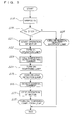
- In the subroutine of FIG. 6, the
controller 1 samples the circuit current Ic values (S30) and determines whether the starting current has converged or not (S33). Thecontroller 1 also samples the battery terminal voltage Vs values during convergence of the starting current (S31). The circuit current Ic and the battery terminal voltage Vs value are sampled every 10 msec. - After sampling the battery terminal voltage Vs value, the
controller 1 accumulates the battery terminal voltage Vs values sampled for 200 msec to obtain a voltage integral value, and compares the voltage integral value with the integral threshold value stored in the storing unit 10 (S32). - When the voltage integral value is less than the integral threshold value, the
controller 1 determines that normal tightening cannot be performed, stops passage of current to the motor M (S34), turns on the "residual quantity shortage lamp" in the display unit 11 (S35), and finishes the control. - The sampling speed of 10 msec and the integral threshold value of 200 msec are examples and the invention is not limited to the values.
- When the integral value is equal to or larger than the integral thresholdvalue, the
controller 1 determines that normal tightening can be performed, confirms convergence of starting current (S33), and returns to step S23. - The subsequent operations are shown in steps S24 to S28 in the flowchart of FIG. 5. Since the operations are the same as those in steps S6 to S10 in the flowchart of FIG. 3, the detailed description will not be repeated.
- In this embodiment, the operation of the motor M can be continued or not is detected from the value obtained by integrating the battery terminal voltage Vs which decreases in association with the starting current of the motor M. Consequently, there is no possibility that malfunction occurs during operation of the motor M obviously in a battery having an insufficient residual quantity but also in a deteriorated battery having a sufficient residual quantity. With a simple configuration which does not require a sensor for measuring the temperature of the battery, means for recording the residual quantity of the battery, and the like, whether the
nut 9 can be tightened or not can be accurately notified to the operator and the motor M can be stopped in advance. - The applicant of the present invention has confirmed that the precision in the case of detecting whether the operation of the motor M can be continued or not from the value obtained by integrating the voltage values is higher than that in the case of determining whether the operation of the motor M can be continued or not from the minimum value of the battery terminal voltage upon start of the motor.
- In the foregoing embodiment, whether the operation of the motor M can be continued or not is detected by comparing the value obtained by integrating the battery terminal voltage Vs which decreases in association with the starting current of the motor M for only predetermined time with the integral threshold value. Alternately, it is also possible to pre-store an integral threshold value obtained by integrating the starting current in the storing
unit 10 and compare a value obtained by integrating the starting current which rises with decrease in the battery terminal voltage Vs for only predetermined time with the integral threshold value, thereby detecting whether the operation of the motor M can be continued or not. - That is, if the value obtained by integrating the current values is less than the threshold value, it is determined that the operation of the motor M cannot be continued. If the integral value is equal to or larger than the threshold value, the operation of the motor M is continued.
- The battery may be a primary battery or a secondary battery. Although a lamp is used to notify the operator that the residual quantity of the battery is insufficient, such as a buzzer may be also used.
Claims (6)
- An electric tightening device comprising:a power source that passes current to a motor (M);a voltage detector that detects a terminal voltage of the power source;a storing unit (10) in which a threshold value of the terminal voltage of the power source is stored; anda controller (1) connected to the voltage detector and the storing unit (10),wherein the controller (1) detects a minimum value of the power source terminal voltage generated upon start of the motor (M) by the voltage detector,compares the voltage minimum value with the threshold value in the storing unit (10) and, when the voltage minimum value is less than the threshold value, notifies of shortage of the power source terminal voltage.
- An electric tightening device comprising:a power source that passes current to a motor (M);a voltage detector that detects a terminal voltage of the power source;a current detector that detects current flowing in the motor (M);a storing unit (10) in which a threshold value of the terminal voltage of the power source is stored; anda controller (1) connected to the voltage detector, the current detector, and the storing unit (10),wherein the controller (1) detects starting current generated upon start of the motor (M) by the current detector, detects a minimum value of the power source voltage generated when the starting current is detected by the voltage detector,compares the voltage minimum value with the threshold value in the storing unit (10) and,when the voltage minimum value is less than the threshold value, notifies of shortage of the power source terminal voltage.
- An electric tightening device comprising:a power source that passes current to a motor (M);a current detector that detects current flowing in the motor (M);a storing unit (10) in which a threshold value of the starting current is stored; anda controller (1) connected to the current detector and the storing unit (10),wherein the controller (1) detects a maximum value of the starting current generated upon start of the motor (M) by the current detector,compares the current maximum value with the threshold value in the storing unit (10) and,when the current maximum value is less than the threshold value, notifies of shortage of the power source terminal voltage.
- An electric tightening device comprising:a power source that passes current to a motor (M);a voltage detector that detects a terminal voltage of the power source;a current detector that detects current flowing in the motor (M);a storing unit (10) in which a threshold value of the starting current is stored; anda controller (1) connected to the voltage detector, the current detector, and the storing unit (10),wherein the controller (1) detects a minimum value of the power source terminal voltage generated upon start of the motor (M) by the voltage detector,detects a maximum value of the starting current obtained when the voltage minimum value is detected by the current detector and,when the current maximum value is less than a threshold value, notifies of shortage of the power source terminal voltage.
- An electric tightening device comprising:a power source that passes current to a motor (M);a voltage detector that detects a terminal voltage of the power source;a storing unit (10) in which a threshold value of a value obtained by integrating the terminal voltage of the power source is stored; anda controller (1) connected to the voltage detector and the storing unit (10),wherein the controller (1) integrates the power source terminal voltage which decreases in association with starting current generated upon start of the motor (M) for only predetermined time,compares the integral voltage value with the threshold value in the storing unit (10) and,when the integral value is less than the threshold value, notifies of shortage of the power source terminal voltage.
- An electric tightening device comprising:a power source that passes current to a motor (M);a current detector that detects current flowing in the motor (M);a storing unit (10) in which a threshold value of a value obtained by integrating the current flowing in the motor (M) is stored; anda controller (1) connected to the current detector and the storing unit (10),wherein the controller (1) integrates the starting current generated upon start of the motor (M) for only predetermined time,compares the integral current value with the threshold value in the storing unit (10) and,when the integral value is less than the threshold value, notifies of shortage of the power source terminal voltage.
Applications Claiming Priority (1)
| Application Number | Priority Date | Filing Date | Title |
|---|---|---|---|
| JP2004348019A JP4368292B2 (en) | 2004-12-01 | 2004-12-01 | Electric clamping machine |
Publications (3)
| Publication Number | Publication Date |
|---|---|
| EP1666905A2 true EP1666905A2 (en) | 2006-06-07 |
| EP1666905A3 EP1666905A3 (en) | 2011-04-27 |
| EP1666905B1 EP1666905B1 (en) | 2021-03-24 |
Family
ID=35945306
Family Applications (1)
| Application Number | Title | Priority Date | Filing Date |
|---|---|---|---|
| EP05025794.8A Active EP1666905B1 (en) | 2004-12-01 | 2005-11-25 | Electric tightening device |
Country Status (7)
| Country | Link |
|---|---|
| US (1) | US7135791B2 (en) |
| EP (1) | EP1666905B1 (en) |
| JP (1) | JP4368292B2 (en) |
| KR (1) | KR101194106B1 (en) |
| CN (1) | CN1781672A (en) |
| CA (1) | CA2528269C (en) |
| TW (1) | TWI340069B (en) |
Cited By (8)
| Publication number | Priority date | Publication date | Assignee | Title |
|---|---|---|---|---|
| US7717191B2 (en) | 2007-11-21 | 2010-05-18 | Black & Decker Inc. | Multi-mode hammer drill with shift lock |
| US7717192B2 (en) | 2007-11-21 | 2010-05-18 | Black & Decker Inc. | Multi-mode drill with mode collar |
| US7735575B2 (en) | 2007-11-21 | 2010-06-15 | Black & Decker Inc. | Hammer drill with hard hammer support structure |
| US7762349B2 (en) | 2007-11-21 | 2010-07-27 | Black & Decker Inc. | Multi-speed drill and transmission with low gear only clutch |
| US7770660B2 (en) | 2007-11-21 | 2010-08-10 | Black & Decker Inc. | Mid-handle drill construction and assembly process |
| US7798245B2 (en) | 2007-11-21 | 2010-09-21 | Black & Decker Inc. | Multi-mode drill with an electronic switching arrangement |
| US7854274B2 (en) | 2007-11-21 | 2010-12-21 | Black & Decker Inc. | Multi-mode drill and transmission sub-assembly including a gear case cover supporting biasing |
| EP2937180A1 (en) | 2014-04-24 | 2015-10-28 | Etablissements Georges Renault | System for controlling an industrial tool by modifying the control signals during usage faults |
Families Citing this family (15)
| Publication number | Priority date | Publication date | Assignee | Title |
|---|---|---|---|---|
| JP5112956B2 (en) * | 2008-05-30 | 2013-01-09 | 株式会社マキタ | Rechargeable power tool |
| JP5668290B2 (en) | 2010-01-14 | 2015-02-12 | 日立工機株式会社 | Electric working machine |
| JP5829006B2 (en) * | 2010-01-14 | 2015-12-09 | 日立工機株式会社 | Electric working machine |
| JP5381871B2 (en) | 2010-03-31 | 2014-01-08 | 日立工機株式会社 | Two-cycle engine and engine working machine equipped with the same |
| GB2481119B (en) * | 2010-06-09 | 2015-11-04 | Chervon Hk Ltd | Battery capacity display for a power tool |
| JP5520177B2 (en) * | 2010-09-22 | 2014-06-11 | パナソニック株式会社 | Battery powered power tool |
| KR101189292B1 (en) * | 2010-11-30 | 2012-10-09 | 현대자동차주식회사 | Apparatus and method for guiding deactivation of battery sensor of ISG vehicles |
| CA2800792C (en) | 2012-01-06 | 2016-10-25 | Sears Brands, Llc | Programmable portable power tool with brushless dc motor |
| CN102837283B (en) * | 2012-09-27 | 2015-03-25 | 北京科瑞思创测控科技有限公司 | Numerical-control constant-torque electric spanner |
| JP2014172163A (en) * | 2013-03-13 | 2014-09-22 | Panasonic Corp | Electric tool |
| CN104175267B (en) * | 2013-05-20 | 2016-08-03 | 南京德朔实业有限公司 | Electric tool and control method thereof |
| CN104034736A (en) * | 2014-05-27 | 2014-09-10 | 楚天科技股份有限公司 | Method for detecting breaking of light examining machine rotation bottle belt |
| DE102015211119A1 (en) * | 2014-06-20 | 2015-12-24 | Robert Bosch Gmbh | Method for controlling an electric motor of a power tool |
| TWI551027B (en) * | 2014-10-01 | 2016-09-21 | de-san Chen | Motor control circuit system |
| CN105743408B (en) * | 2014-12-12 | 2018-06-26 | 陈德三 | The control circuit system of motor |
Citations (2)
| Publication number | Priority date | Publication date | Assignee | Title |
|---|---|---|---|---|
| EP0676835A2 (en) | 1994-04-08 | 1995-10-11 | Framatome Connectors International | Hand held compression tool |
| JP2000117649A (en) | 1998-10-08 | 2000-04-25 | Maeda Metal Industries Ltd | Forward and reverse rotation switching device of motor- driven fastening tool |
Family Cites Families (11)
| Publication number | Priority date | Publication date | Assignee | Title |
|---|---|---|---|---|
| DE3236033A1 (en) * | 1982-09-29 | 1984-03-29 | Robert Bosch Gmbh, 7000 Stuttgart | SCREW DEVICE |
| JPS6188731A (en) * | 1984-10-04 | 1986-05-07 | シャープ株式会社 | Charge-discharge controller |
| US5144248A (en) * | 1989-05-22 | 1992-09-01 | Alexander Manufacturing Company | Method and apparatus for measuring the voltage and charge of a battery |
| US5357203A (en) * | 1992-07-08 | 1994-10-18 | Benchmarq Microelectronics, Inc. | Battery monitoring circuit for operating with high battery discharge rates |
| US5451881A (en) * | 1993-12-10 | 1995-09-19 | Curtis Instruments, Inc. | Method and means for adjusting battery monitor based on rate of current drawn from the battery |
| DE19818755A1 (en) * | 1998-04-27 | 1999-11-04 | Honsel M H Beteiligungs Gmbh | Rivet setting tool |
| JP2000176854A (en) * | 1998-12-11 | 2000-06-27 | Makita Corp | Battery type fastening tool |
| US6771043B2 (en) * | 2001-05-09 | 2004-08-03 | Makita Corporation | Power tools |
| JP3883863B2 (en) * | 2001-05-09 | 2007-02-21 | 株式会社マキタ | Battery power tool and battery remaining capacity detection method for battery power tool |
| US6765317B2 (en) * | 2002-04-02 | 2004-07-20 | Defond Manufacturing Limited | Power supply module for electrical power tools |
| US6847191B1 (en) * | 2003-08-13 | 2005-01-25 | Kinpo Electronics, Inc. | Power control device and the operating method thereof |
-
2004
- 2004-12-01 JP JP2004348019A patent/JP4368292B2/en active Active
-
2005
- 2005-11-08 TW TW094139148A patent/TWI340069B/en active
- 2005-11-10 KR KR1020050107560A patent/KR101194106B1/en active IP Right Grant
- 2005-11-23 US US11/286,759 patent/US7135791B2/en active Active
- 2005-11-25 EP EP05025794.8A patent/EP1666905B1/en active Active
- 2005-11-28 CA CA2528269A patent/CA2528269C/en active Active
- 2005-12-01 CN CNA2005101288214A patent/CN1781672A/en active Pending
Patent Citations (2)
| Publication number | Priority date | Publication date | Assignee | Title |
|---|---|---|---|---|
| EP0676835A2 (en) | 1994-04-08 | 1995-10-11 | Framatome Connectors International | Hand held compression tool |
| JP2000117649A (en) | 1998-10-08 | 2000-04-25 | Maeda Metal Industries Ltd | Forward and reverse rotation switching device of motor- driven fastening tool |
Cited By (12)
| Publication number | Priority date | Publication date | Assignee | Title |
|---|---|---|---|---|
| US7717191B2 (en) | 2007-11-21 | 2010-05-18 | Black & Decker Inc. | Multi-mode hammer drill with shift lock |
| US7717192B2 (en) | 2007-11-21 | 2010-05-18 | Black & Decker Inc. | Multi-mode drill with mode collar |
| US7735575B2 (en) | 2007-11-21 | 2010-06-15 | Black & Decker Inc. | Hammer drill with hard hammer support structure |
| US7762349B2 (en) | 2007-11-21 | 2010-07-27 | Black & Decker Inc. | Multi-speed drill and transmission with low gear only clutch |
| US7770660B2 (en) | 2007-11-21 | 2010-08-10 | Black & Decker Inc. | Mid-handle drill construction and assembly process |
| US7798245B2 (en) | 2007-11-21 | 2010-09-21 | Black & Decker Inc. | Multi-mode drill with an electronic switching arrangement |
| US7854274B2 (en) | 2007-11-21 | 2010-12-21 | Black & Decker Inc. | Multi-mode drill and transmission sub-assembly including a gear case cover supporting biasing |
| US7987920B2 (en) | 2007-11-21 | 2011-08-02 | Black & Decker Inc. | Multi-mode drill with mode collar |
| US8109343B2 (en) | 2007-11-21 | 2012-02-07 | Black & Decker Inc. | Multi-mode drill with mode collar |
| US8292001B2 (en) | 2007-11-21 | 2012-10-23 | Black & Decker Inc. | Multi-mode drill with an electronic switching arrangement |
| EP2937180A1 (en) | 2014-04-24 | 2015-10-28 | Etablissements Georges Renault | System for controlling an industrial tool by modifying the control signals during usage faults |
| FR3020301A1 (en) * | 2014-04-24 | 2015-10-30 | Renault Georges Ets | SYSTEM FOR CONTROLLING AN INDISTRITIC TOOL BY MODIFYING CONTROL SIGNALS DURING USE DEFECTS |
Also Published As
| Publication number | Publication date |
|---|---|
| JP2006150547A (en) | 2006-06-15 |
| EP1666905A3 (en) | 2011-04-27 |
| KR20060061224A (en) | 2006-06-07 |
| JP4368292B2 (en) | 2009-11-18 |
| US7135791B2 (en) | 2006-11-14 |
| CN1781672A (en) | 2006-06-07 |
| CA2528269A1 (en) | 2006-06-01 |
| US20060113934A1 (en) | 2006-06-01 |
| TWI340069B (en) | 2011-04-11 |
| EP1666905B1 (en) | 2021-03-24 |
| TW200633816A (en) | 2006-10-01 |
| KR101194106B1 (en) | 2012-10-24 |
| CA2528269C (en) | 2014-02-04 |
Similar Documents
| Publication | Publication Date | Title |
|---|---|---|
| CA2528269C (en) | Electric tightening device | |
| US6466025B1 (en) | Alternator tester | |
| US6771043B2 (en) | Power tools | |
| US6252377B1 (en) | Apparatus for detecting remaining charge of battery | |
| US20090108674A1 (en) | Power Supply Control Device and Method of Detecting Abnormality of Relay | |
| US10926386B2 (en) | Impact rotary tool | |
| US6330140B1 (en) | Method of and circuit for testing an electrical actuator drive stage | |
| US5675236A (en) | Low battery power state determination apparatus and method for secondary battery | |
| US20010043054A1 (en) | Method and apparatus for detecting a disconnection in the charge line between a generator and an electric battery in a motor vehicle | |
| JP3883863B2 (en) | Battery power tool and battery remaining capacity detection method for battery power tool | |
| JP2003512006A (en) | Auto-detector for generator type of automobile | |
| US5627452A (en) | Charging method of secondary battery | |
| EP1485979B1 (en) | Microprocessor controlled booster apparatus with polarity protection | |
| TWI258063B (en) | Apparatus for prevention of forgetting screw tightening | |
| JPH08293238A (en) | Detecting circuit for checking contact of relay | |
| JP2004071556A (en) | Method and apparatus for determining power source classification, and power source apparatus | |
| JPH05164058A (en) | Air conditioner | |
| JP2755536B2 (en) | Device with battery status detection function | |
| JPH08255636A (en) | Battery kind discriminating device and battery driving equipment | |
| WO2005041621A1 (en) | Electric-discharge lamp lighting apparatus | |
| JPH09149558A (en) | Charge controller | |
| JP3535551B2 (en) | Electronically controlled failsafe device | |
| JP2568701Y2 (en) | Battery charging circuit | |
| JPH07153635A (en) | Malfunction monitoring device of on-load tap changer | |
| JP2959289B2 (en) | Screw tightening control device |
Legal Events
| Date | Code | Title | Description |
|---|---|---|---|
| PUAI | Public reference made under article 153(3) epc to a published international application that has entered the european phase |
Free format text: ORIGINAL CODE: 0009012 |
|
| AK | Designated contracting states |
Kind code of ref document: A2 Designated state(s): AT BE BG CH CY CZ DE DK EE ES FI FR GB GR HU IE IS IT LI LT LU LV MC NL PL PT RO SE SI SK TR |
|
| AX | Request for extension of the european patent |
Extension state: AL BA HR MK YU |
|
| RIN1 | Information on inventor provided before grant (corrected) |
Inventor name: TORIGAI, YUKIO Inventor name: KUSHIDA, TOSHIHIKO |
|
| PUAL | Search report despatched |
Free format text: ORIGINAL CODE: 0009013 |
|
| AK | Designated contracting states |
Kind code of ref document: A3 Designated state(s): AT BE BG CH CY CZ DE DK EE ES FI FR GB GR HU IE IS IT LI LT LU LV MC NL PL PT RO SE SI SK TR |
|
| AX | Request for extension of the european patent |
Extension state: AL BA HR MK YU |
|
| 17P | Request for examination filed |
Effective date: 20111017 |
|
| AKX | Designation fees paid |
Designated state(s): DE FR GB IT |
|
| 17Q | First examination report despatched |
Effective date: 20140422 |
|
| STAA | Information on the status of an ep patent application or granted ep patent |
Free format text: STATUS: EXAMINATION IS IN PROGRESS |
|
| REG | Reference to a national code |
Ref country code: DE Ref legal event code: R079 Ref document number: 602005057173 Country of ref document: DE Free format text: PREVIOUS MAIN CLASS: G01R0031400000 Ipc: B25B0023147000 |
|
| RIC1 | Information provided on ipc code assigned before grant |
Ipc: G01R 31/40 20200101ALI20200915BHEP Ipc: B25B 23/147 20060101AFI20200915BHEP Ipc: G01R 31/36 20200101ALI20200915BHEP Ipc: G01R 31/3842 20190101ALI20200915BHEP Ipc: G01R 19/165 20060101ALI20200915BHEP Ipc: G01R 31/3828 20190101ALI20200915BHEP Ipc: B25B 21/00 20060101ALI20200915BHEP |
|
| GRAP | Despatch of communication of intention to grant a patent |
Free format text: ORIGINAL CODE: EPIDOSNIGR1 |
|
| STAA | Information on the status of an ep patent application or granted ep patent |
Free format text: STATUS: GRANT OF PATENT IS INTENDED |
|
| INTG | Intention to grant announced |
Effective date: 20201026 |
|
| GRAS | Grant fee paid |
Free format text: ORIGINAL CODE: EPIDOSNIGR3 |
|
| GRAA | (expected) grant |
Free format text: ORIGINAL CODE: 0009210 |
|
| STAA | Information on the status of an ep patent application or granted ep patent |
Free format text: STATUS: THE PATENT HAS BEEN GRANTED |
|
| AK | Designated contracting states |
Kind code of ref document: B1 Designated state(s): DE FR GB IT |
|
| REG | Reference to a national code |
Ref country code: GB Ref legal event code: FG4D |
|
| REG | Reference to a national code |
Ref country code: DE Ref legal event code: R096 Ref document number: 602005057173 Country of ref document: DE |
|
| REG | Reference to a national code |
Ref country code: DE Ref legal event code: R097 Ref document number: 602005057173 Country of ref document: DE |
|
| PLBE | No opposition filed within time limit |
Free format text: ORIGINAL CODE: 0009261 |
|
| STAA | Information on the status of an ep patent application or granted ep patent |
Free format text: STATUS: NO OPPOSITION FILED WITHIN TIME LIMIT |
|
| 26N | No opposition filed |
Effective date: 20220104 |
|
| PGFP | Annual fee paid to national office [announced via postgrant information from national office to epo] |
Ref country code: GB Payment date: 20231123 Year of fee payment: 19 |
|
| PGFP | Annual fee paid to national office [announced via postgrant information from national office to epo] |
Ref country code: IT Payment date: 20231130 Year of fee payment: 19 Ref country code: FR Payment date: 20231124 Year of fee payment: 19 Ref country code: DE Payment date: 20231128 Year of fee payment: 19 |