EP1670370B1 - Medical retrieval devices - Google Patents
Medical retrieval devices Download PDFInfo
- Publication number
- EP1670370B1 EP1670370B1 EP04781437A EP04781437A EP1670370B1 EP 1670370 B1 EP1670370 B1 EP 1670370B1 EP 04781437 A EP04781437 A EP 04781437A EP 04781437 A EP04781437 A EP 04781437A EP 1670370 B1 EP1670370 B1 EP 1670370B1
- Authority
- EP
- European Patent Office
- Prior art keywords
- sheath
- legs
- basket
- retrieval assembly
- proximal
- Prior art date
- Legal status (The legal status is an assumption and is not a legal conclusion. Google has not performed a legal analysis and makes no representation as to the accuracy of the status listed.)
- Not-in-force
Links
- 0 CCCNCC(*)*C Chemical compound CCCNCC(*)*C 0.000 description 1
Images


Classifications
-
- A—HUMAN NECESSITIES
- A61—MEDICAL OR VETERINARY SCIENCE; HYGIENE
- A61B—DIAGNOSIS; SURGERY; IDENTIFICATION
- A61B17/00—Surgical instruments, devices or methods, e.g. tourniquets
- A61B17/22—Implements for squeezing-off ulcers or the like on the inside of inner organs of the body; Implements for scraping-out cavities of body organs, e.g. bones; Calculus removers; Calculus smashing apparatus; Apparatus for removing obstructions in blood vessels, not otherwise provided for
- A61B17/221—Gripping devices in the form of loops or baskets for gripping calculi or similar types of obstructions
-
- A—HUMAN NECESSITIES
- A61—MEDICAL OR VETERINARY SCIENCE; HYGIENE
- A61B—DIAGNOSIS; SURGERY; IDENTIFICATION
- A61B17/00—Surgical instruments, devices or methods, e.g. tourniquets
- A61B17/32—Surgical cutting instruments
- A61B17/3205—Excision instruments
- A61B17/32056—Surgical snare instruments
-
- A—HUMAN NECESSITIES
- A61—MEDICAL OR VETERINARY SCIENCE; HYGIENE
- A61B—DIAGNOSIS; SURGERY; IDENTIFICATION
- A61B18/00—Surgical instruments, devices or methods for transferring non-mechanical forms of energy to or from the body
- A61B18/18—Surgical instruments, devices or methods for transferring non-mechanical forms of energy to or from the body by applying electromagnetic radiation, e.g. microwaves
- A61B18/20—Surgical instruments, devices or methods for transferring non-mechanical forms of energy to or from the body by applying electromagnetic radiation, e.g. microwaves using laser
- A61B18/22—Surgical instruments, devices or methods for transferring non-mechanical forms of energy to or from the body by applying electromagnetic radiation, e.g. microwaves using laser the beam being directed along or through a flexible conduit, e.g. an optical fibre; Couplings or hand-pieces therefor
- A61B18/26—Surgical instruments, devices or methods for transferring non-mechanical forms of energy to or from the body by applying electromagnetic radiation, e.g. microwaves using laser the beam being directed along or through a flexible conduit, e.g. an optical fibre; Couplings or hand-pieces therefor for producing a shock wave, e.g. laser lithotripsy
-
- A—HUMAN NECESSITIES
- A61—MEDICAL OR VETERINARY SCIENCE; HYGIENE
- A61B—DIAGNOSIS; SURGERY; IDENTIFICATION
- A61B17/00—Surgical instruments, devices or methods, e.g. tourniquets
- A61B17/00234—Surgical instruments, devices or methods, e.g. tourniquets for minimally invasive surgery
- A61B2017/00292—Surgical instruments, devices or methods, e.g. tourniquets for minimally invasive surgery mounted on or guided by flexible, e.g. catheter-like, means
- A61B2017/003—Steerable
- A61B2017/00305—Constructional details of the flexible means
- A61B2017/00314—Separate linked members
-
- A—HUMAN NECESSITIES
- A61—MEDICAL OR VETERINARY SCIENCE; HYGIENE
- A61B—DIAGNOSIS; SURGERY; IDENTIFICATION
- A61B17/00—Surgical instruments, devices or methods, e.g. tourniquets
- A61B17/22—Implements for squeezing-off ulcers or the like on the inside of inner organs of the body; Implements for scraping-out cavities of body organs, e.g. bones; Calculus removers; Calculus smashing apparatus; Apparatus for removing obstructions in blood vessels, not otherwise provided for
- A61B2017/22051—Implements for squeezing-off ulcers or the like on the inside of inner organs of the body; Implements for scraping-out cavities of body organs, e.g. bones; Calculus removers; Calculus smashing apparatus; Apparatus for removing obstructions in blood vessels, not otherwise provided for with an inflatable part, e.g. balloon, for positioning, blocking, or immobilisation
- A61B2017/22065—Functions of balloons
- A61B2017/22069—Immobilising; Stabilising
-
- A—HUMAN NECESSITIES
- A61—MEDICAL OR VETERINARY SCIENCE; HYGIENE
- A61B—DIAGNOSIS; SURGERY; IDENTIFICATION
- A61B17/00—Surgical instruments, devices or methods, e.g. tourniquets
- A61B17/22—Implements for squeezing-off ulcers or the like on the inside of inner organs of the body; Implements for scraping-out cavities of body organs, e.g. bones; Calculus removers; Calculus smashing apparatus; Apparatus for removing obstructions in blood vessels, not otherwise provided for
- A61B17/221—Gripping devices in the form of loops or baskets for gripping calculi or similar types of obstructions
- A61B2017/2212—Gripping devices in the form of loops or baskets for gripping calculi or similar types of obstructions having a closed distal end, e.g. a loop
-
- A—HUMAN NECESSITIES
- A61—MEDICAL OR VETERINARY SCIENCE; HYGIENE
- A61B—DIAGNOSIS; SURGERY; IDENTIFICATION
- A61B17/00—Surgical instruments, devices or methods, e.g. tourniquets
- A61B17/22—Implements for squeezing-off ulcers or the like on the inside of inner organs of the body; Implements for scraping-out cavities of body organs, e.g. bones; Calculus removers; Calculus smashing apparatus; Apparatus for removing obstructions in blood vessels, not otherwise provided for
- A61B17/221—Gripping devices in the form of loops or baskets for gripping calculi or similar types of obstructions
- A61B2017/2215—Gripping devices in the form of loops or baskets for gripping calculi or similar types of obstructions having an open distal end
-
- A—HUMAN NECESSITIES
- A61—MEDICAL OR VETERINARY SCIENCE; HYGIENE
- A61B—DIAGNOSIS; SURGERY; IDENTIFICATION
- A61B17/00—Surgical instruments, devices or methods, e.g. tourniquets
- A61B17/22—Implements for squeezing-off ulcers or the like on the inside of inner organs of the body; Implements for scraping-out cavities of body organs, e.g. bones; Calculus removers; Calculus smashing apparatus; Apparatus for removing obstructions in blood vessels, not otherwise provided for
- A61B17/221—Gripping devices in the form of loops or baskets for gripping calculi or similar types of obstructions
- A61B2017/2217—Gripping devices in the form of loops or baskets for gripping calculi or similar types of obstructions single wire changing shape to a gripping configuration
-
- A—HUMAN NECESSITIES
- A61—MEDICAL OR VETERINARY SCIENCE; HYGIENE
- A61B—DIAGNOSIS; SURGERY; IDENTIFICATION
- A61B17/00—Surgical instruments, devices or methods, e.g. tourniquets
- A61B17/28—Surgical forceps
- A61B17/29—Forceps for use in minimally invasive surgery
- A61B2017/2901—Details of shaft
- A61B2017/2902—Details of shaft characterized by features of the actuating rod
-
- A—HUMAN NECESSITIES
- A61—MEDICAL OR VETERINARY SCIENCE; HYGIENE
- A61B—DIAGNOSIS; SURGERY; IDENTIFICATION
- A61B17/00—Surgical instruments, devices or methods, e.g. tourniquets
- A61B17/28—Surgical forceps
- A61B17/29—Forceps for use in minimally invasive surgery
- A61B2017/2901—Details of shaft
- A61B2017/2905—Details of shaft flexible
-
- A—HUMAN NECESSITIES
- A61—MEDICAL OR VETERINARY SCIENCE; HYGIENE
- A61B—DIAGNOSIS; SURGERY; IDENTIFICATION
- A61B90/00—Instruments, implements or accessories specially adapted for surgery or diagnosis and not covered by any of the groups A61B1/00 - A61B50/00, e.g. for luxation treatment or for protecting wound edges
- A61B90/30—Devices for illuminating a surgical field, the devices having an interrelation with other surgical devices or with a surgical procedure
- A61B2090/306—Devices for illuminating a surgical field, the devices having an interrelation with other surgical devices or with a surgical procedure using optical fibres
Definitions
- Embodiments of this invention generally relate to medical devices, and, more particularly, to medical devices for assisting in the removal of stones or other biological and/or foreign material from the body of a patient.
- a surgical retrieval device may be used, for example, to retrieve calculi from a body.
- the device may be used through an endoscope or a laparoscope, or it may be used without the aid of an endoscope or a laparoscope.
- One type of surgical retrieval device has a sheath and a basket formed from wires.
- the basket is moveable in and out of the sheath.
- the basket may be collapsed within the sheath to achieve a reduced diameter profile.
- the basket may be opened when it extends beyond the distal end of the sheath.
- Some retrieval devices include wires grouped together inside a cannula with the wires joined via soldering or welding to form a ball. Manufacturing of such devices may be costly and time consuming. Other devices have wires that are twisted and/or knotted together to eliminate a welded or soldered tip at the distal end of a basket. The tips of such devices may hinder access to calculi and may increase the possibility of tissue damage. Examples of devices according to the prior art are disclosed in US 5520697 , DE 19722429 , WO 01/97699 , US 4811735 , US 4174715 and US 5944728 . US 2004/054377 discloses a device according to the preamble of claim 1.
- a medical device includes an elongate member and a retrieval assembly extending distally from the elongate member and formed from a same piece of material as the elongate member.
- the retrieval assembly is formed by removing at least a portion of the same piece of material.
- the same piece of material is a hollow tube.
- the retrieval assembly further includes at least one leg.
- the device includes an optical fiber extending through a lumen defined by the tube, and the at least one leg may include a ramp portion to assist in positioning the optical fiber.
- the device in another embodiment, includes a sheath defining a lumen, the retrieval assembly having a collapsed state in which the retrieval assembly is substantially disposed within the lumen of the sheath, and an expanded state in which the retrieval assembly is substantially outside of the lumen of the sheath.
- the sheath defines at least one cutout to alter the flexibility of the sheath.
- the retrieval assembly comprises a plurality of legs, each .of the plurality of legs including a free distal end. In such an embodiment of the device, the plurality of legs are configured to transition from a substantially straight configuration when the retrieval assembly is in the collapsed state to a substantially curled configuration when the retrieval assembly is in the expanded state.
- Each of the plurality of legs when in the substantially curled configuration, is curled back towards a proximal end of the device.
- the plurality of legs are configured to contact a biologic or foreign material in the substantially curled configuration to assist in removing the biologic or foreign material.
- the plurality of legs are configured to contact the biologic or foreign material as each free distal end is brought together by advancing the sheath toward the free distal ends.
- Each of the free distal ends includes at least one textured surface to assist in grasping the biologic or foreign material.
- the elongate member defines at least one lumen.
- An optical fiber is disposed within the at least one lumen of the elongate member.
- the retrieval assembly further includes a plurality of legs and a tension member attached to each of the plurality of legs for manipulating a corresponding leg.
- Each tension member extends at least partially through a lumen defined by the elongate member.
- Each tension member is attached to a free end of the corresponding leg.
- Each tension member exits from an aperture defined by a side of the elongate member.
- the elongate member defines at least one hole at a proximal end of the retrieval assembly, at least a portion of a proximal portion of the elongate member is removed to define corresponding interlocking portions, and the retrieval assembly further comprises a plurality of legs joined at a distal end.
- the device further includes a sheath defining a lumen, the retrieval assembly having a collapsed state in which the retrieval assembly is substantially disposed within the lumen of the sheath, and an expanded state in which the retrieval assembly is substantially outside of the lumen of the sheath.
- the retrieval assembly comprises two opposing loops configured to move toward each other when the retrieval assembly transitions from an expanded state to a collapsed state.
- Each of the two opposing loops includes a textured inward facing surface to assist in grasping biologic or foreign material.
- the two opposing loops are joined to form a single continuous loop having a curved state with a free proximal end when the retrieval assembly is in an expanded state.
- the retrieval assembly further includes netting attached to at least a portion of the continuous loop.
- the retrieval assembly includes a plurality of proximal legs extending to a plurality of distal legs, the distal legs being joined at a distal end of the retrieval assembly.
- the plurality of proximal legs includes a first proximal leg joining a proximal end of at least two of the plurality of distal legs, and a second proximal leg joining a proximal end of at least two other of the plurality of distal legs.
- the plurality of distal legs includes six legs.
- the retrieval assembly includes a continuous loop. The same piece of material is hollow and defines at least one lumen. The continuous loop includes a plurality of teeth. The distal end includes at least one spike.
- the retrieval assembly further includes a plurality of legs on only one side of the loop, each leg extending from a proximal end to a distal end of the loop.
- a medical device in another embodiment, includes a basket made of shape memory material and comprising a plurality of legs and a netting, a distal end of a first leg of the plurality of legs being configured to curve away from a distal end of a second leg of the plurality of legs when the basket is in a substantially open position, and the netting being connected to a distal end of each of the plurality of legs and an elongate member connected to a proximal end of the basket and disposed within a lumen of a sheath, the basket having a collapsed state in which the basket is substantially disposed within the lumen of the sheath, and an expanded state in which the basket is substantially outside of the lumen of the sheath.
- the netting is made of shape memory material.
- the basket is configured to assume an umbrella-like shape in the expanded state to assist in immobilizing a stone.
- Each of the plurality of legs are substantially evenly spaced apart.
- a medical device in still another embodiment, includes a basket made of shape memory material and comprising a substantially spiral-shaped leg and a free distal end curved toward a proximal end of the leg and an elongate member connected to a proximal end of the basket and disposed within a lumen of a sheath of the device, the basket having a collapsed state in which the basket is substantially disposed within the lumen of the sheath and an expanded state in which the basket is substantially outside of the lumen of the sheath.
- the basket includes a single leg.
- a medical device in a further embodiment of the present disclosure, includes a sheath defining a lumen, an elongate actuation member disposed within the lumen of the sheath and longitudinally moveable relative to the sheath, and a basket including a plurality of legs, a distal end of each of the plurality of legs being fixed to the sheath, a proximal end of each of the plurality of legs being fixed to the elongate actuation member, wherein movement of the elongate actuation member distally relative to the sheath expands the basket.
- the distal end of each of the plurality of legs is fixed a distal end of the sheath.
- the device includes a crimp ring configured to fixedly connect each of the plurality of legs to the sheath.
- the crimp ring fixedly connects each of the plurality of legs to an inner surface of the sheath. At least a portion of each of the plurality of legs extends proximate to an outside surface of the sheath when the basket is in a closed position.
- the sheath defines a plurality of ports along a length of the sheath, the ports configured to accept at least one of the plurality of legs.
- the number of the plurality of ports is equal to the number of the plurality of legs.
- Each of the plurality of legs is made of a shape memory material.
- the elongate actuation member is hollow and a proximal end of each of the plurality of legs is connected to a distal end of the elongate actuation member.
- a medical device in another embodiment, includes a sheath defining a lumen, an elongate actuation member disposed within the lumen of the sheath and longitudinally moveable relative to the sheath, a stabilizing member at least partially disposed within a lumen of the elongate actuation member, the stabilizing member being longitudinally moveable relative to the elongate actuation member, and a basket including a plurality of legs, a distal end of each of the plurality of legs being coupled to the stabilizing member, a proximal end of each of the plurality of legs being coupled to the elongate actuation member, and at least a portion of each of the plurality of legs extending proximate to an outside surface of the sheath when the basket is in a closed position.
- the sheath defines a plurality of ports along a length of the sheath, the ports configured to accept at least one of the plurality of legs.
- the number of the plurality of ports is equal to the number of the plurality of legs.
- the basket is configured to transition between an expanded position and a collapsed position by manipulating the elongate actuation member relative to the stabilizing member.
- a medical device in still another embodiment, includes a sheath defining a lumen, an elongate actuation member disposed within the lumen of the sheath and longitudinally moveable relative to the sheath, a stabilizing member at least partially disposed within the elongate actuation member and longitudinally moveable relative to the elongate actuation member within the lumen of the sheath, and a basket including a plurality of legs, a distal end of each of the plurality of legs being fixed to a distal end of the stabilizing member, a proximal end of each of the plurality of legs being fixed to the elongate actuation member, and each of the plurality of legs being substantially entirely disposed within the lumen of the sheath when the basket is in a closed position. At least a portion of the basket expands from a distal end of the sheath as the elongate actuation member is advanced toward the distal end of the sheath.
- a medical device in yet another embodiment, includes a sheath defining a lumen, an elongate actuation member disposed within the lumen of the sheath and longitudinally moveable relative to the sheath, a proximal basket including a plurality of proximal legs, a distal end of each of the plurality of proximal legs being connected to a surface of the sheath, and a distal basket including a plurality of distal legs, a proximal end of each of the plurality of distal legs being connected to a distal end of the elongate actuation member. At least a portion of the basket expands from a distal end of the sheath as the elongate actuation member is advanced toward the distal end of the sheath.
- a medical device in still another embodiment, includes a sheath defining a lumen, an elongate actuation member disposed within the lumen of the sheath and longitudinally moveable relative to the sheath, a proximal basket including a plurality of proximal legs, a distal end of each of the plurality of proximal legs being connected to a surface of the sheath, and a distal basket including a plurality of distal legs, a proximal end of each of the plurality of distal legs being connected to a distal end of the elongate actuation member.
- the surface of the sheath is an inner surface of the sheath.
- a proximal end of each of the plurality of proximal legs is connected to the elongate actuation member and the elongate actuation member is configured to manipulate at least a portion of the proximal basket.
- the sheath defines a plurality of ports configured to accept at least one of the plurality of proximal legs. In such a device, the number of the plurality of ports is equal to the number of the plurality of proximal legs. At least a portion of each of the plurality of proximal legs extends proximate to an outside surface of the sheath when the proximal basket is in a closed position.
- the proximal basket and the distal basket are configured to transition between respective expanded positions and collapsed positions substantially in unison.
- Such a device also includes an extending member disposed within the at least one lumen of the sheath and defining an extending member lumen, the elongate actuation member being disposed within the extending member lumen.
- a proximal end of each of the plurality of proximal legs is connected to the extending member.
- the sheath defines a plurality of ports configured to accept at least one of the plurality of proximal legs.
- the number of the plurality of ports is equal to the number of the plurality of proximal legs.
- At least a portion of each of the plurality of proximal legs extends proximate to an outside surface of the sheath when the proximal basket is in a closed position.
- the proximal basket and the distal basket are independently maneuverable.
- a medical device in a further embodiment of the present disclosure, includes a sheath defining a lumen, a shaft disposed within the lumen and moveable relative to the lumen, and a retrieval assembly including a plurality of legs comprising a shape memory material, each of the plurality of legs having a proximal end fixedly attached to a distal end of the shaft, and a free distal end extending in a proximal direction beyond the distal end of the shaft when the retrieval assembly is in a substantially expanded position.
- Each of the plurality of legs is formed of the shaft.
- the retrieval assembly achieves the substantially expanded position as the sheath is moved in a proximal direction relative to the shaft.
- Each of the plurality of legs achieves a substantially circular shape when the retrieval assembly is in the substantially expanded position.
- a method of making a medical device includes providing an elongate member, and removing at least a portion of the elongate member to form a retrieval assembly, the retrieval assembly comprising at least two loops, each of the at least two loops having a proximal end integral with the elongate member.
- the method may further include forming a plurality of teeth on a surface of each of the at least two loops, removing at least a portion of a proximal portion of the elongate member to define corresponding interlocking portions, forming at least one hole at the proximal ends of the at least two loops, and detaching a portion of each of the at least two loops from the elongate member so as to form a single loop, the single loop having a free distal end and a proximal end that is connected to the elongate member.
- the at least two loops are connected only at the proximal ends.
- the method may further include providing a netting connected to at least a portion of the single loop.
- a method of making a medical device includes providing an elongate member and removing a portion of the elongate member to form a retrieval assembly, the retrieval assembly comprising at least two proximal legs extending to a plurality of distal legs, each of the plurality of distal legs being connected at a distal end portion of the retrieval assembly.
- the removing step includes first removing a portion of the elongate member to form two legs and then removing a portion of the two legs to form the two proximal legs and the plurality of distal legs.
- the elongate member defines at least one lumen.
- An exemplary method for removing a stone from a body includes providing a medical device comprising an elongate member and a retrieval assembly comprising a plurality of legs, a proximal end of each of the plurality of legs being connected to the elongate member and a distal end of each of the plurality of legs being connected to a corresponding tension member, positioning the retrieval assembly adjacent to the stone, expanding the retrieval assembly by releasing the tension members, and capturing the stone with the retrieval assembly.
- the capturing the stone further includes manipulating at least one of the tension members toward a proximal end of the device.
- the method may further include manipulating each of the legs independently via the corresponding tension members. Each of the tension members extends through a lumen of the elongate member.
- a further exemplary method for immobilizing a stone within a body includes providing a medical device comprising a sheath, an elongate actuation member disposed within a lumen of the sheath, a proximal basket including a plurality of proximal legs, and a distal basket including a plurality of distal legs, positioning a distal end of the sheath distal the stone, expanding the distal basket, and expanding the proximal basket.
- the expanding the distal basket includes manipulating the elongate actuation member in a distal direction.
- the expanding the proximal basket includes manipulating the elongate actuation member in a distal direction.
- the proximal basket and the distal basket expand in unison.
- the expanding the proximal basket includes manipulating an extending member disposed within the lumen of the sheath and moveable independent of the elongate actuation member.
- the proximal basket and the distal basket expand independently.
- the proximal basket is expanded proximal to the stone and the distal basket is expanded distal to the stone.
- FIG. 1 is a cross-sectional view of a stone removal assistance device according to an exemplary embodiment of the present disclosure.
- FIG. 2 is a side view of a portion of a stone removal assistance device according to an exemplary embodiment of the present disclosure.
- FIG. 2a is a cross-sectional view of the device illustrated in FIG. 2 .
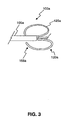
- FIG. 3 is a partial view of the device of FIG. 2 .
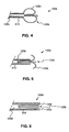
- FIG. 4 is a cross-sectional view of a portion of a stone removal assistance device according to another embodiment of the present disclosure.
- FIG. 5 is a cross-sectional view of the device of FIG. 4 .
- FIG. 6 is another cross-sectional view of the device of FIG. 4 .
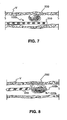
- FIG. 7 is an operational view of the device of FIG. 4 .
- FIG. 8 is another operational view of the device of FIG. 4 .
- FIG. 9 is a cross-sectional view of a stone removal assistance device according to another embodiment of the present disclosure.
- FIG. 10 is a side view of a portion of a stone removal assistance device according to still another embodiment of the present disclosure.
- FIG. 11 is a side view of a portion of a stone removal assistance device according to yet another embodiment of the present disclosure.
- FIG. 12 is a plan view of the device of FIG. 11 .
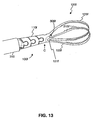
- FIG. 13 is a plan view of a portion of a stone removal assistance device according to a further embodiment of the present disclosure.
- FIG. 14 is a side view of the device of FIG. 13 .
- FIG. 15 is a top view of the device of FIG. 14 .
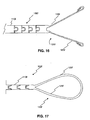
- FIG. 16 is another side view of the device of FIG. 13 .
- FIG. 17 is a top view of the device of FIG. 16 .
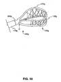
- FIG. 18 is a plan view of a portion of a stone removal assistance device according to a still further embodiment of the present disclosure.
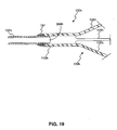
- FIG. 19 is a cross-sectional view of a portion of a stone removal assistance device according to another embodiment of the present disclosure.
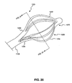
- FIG. 20 is a plan view of a portion of a stone removal assistance device according to still another embodiment of the present disclosure.
- FIG. 21 is a cross-sectional view of the device of FIG. 20 .
- FIG. 22 is a plan view of a portion of a stone removal assistance device according to yet another embodiment of the present disclosure.
- FIG. 23 is a side view of the device of FIG. 22 .
- FIG. 24 is a portion of a leg of the device of FIG. 22 .
- FIG. 25 is an operational view of the device of FIG. 22 .
- FIG. 26 is an operational view of a portion of a stone removal assistance device according to another embodiment of the present disclosure.
- FIG. 27 is an end view of the device of FIG. 26 .
- FIG. 28 is a plan view of the device of FIG. 26 .
- FIG. 29 is an operational view of a portion of a stone removal assistance device according to still another embodiment of the present disclosure.
- FIG. 30 is an end view of the device of FIG. 29 .
- FIG. 31 is a partial cutaway view of a portion of a stone removal assistance device according to yet another embodiment of the present disclosure.
- FIG. 32 is a cross-sectional view of a distal end of the device of FIG. 31 .
- FIG. 33 is an expanded basket of the device of FIG. 31 .
- FIG. 34 is a leg for use in a stone removal assistance device.
- FIG. 35 is another leg for use in a stone removal assistance device.
- FIG. 36 is a further leg for use in a stone removal assistance device.
- FIG. 37 is a partial cutaway view of a portion of a stone removal assistance device according to a further embodiment of the present disclosure.
- FIG. 38 is a cross-sectional view of a portion of a stone removal assistance device according to a still further embodiment of the present disclosure.
- FIG. 39 is a cross-sectional view of a portion of a stone removal assistance device according to another embodiment of the present disclosure.
- FIG. 40 is a cross-sectional view of the device of FIG. 39 .
- FIG. 41 is a cross-sectional view of a portion of a stone removal assistance device according to yet another embodiment of the present disclosure.
- FIG. 42 is a cross-sectional view of the device of FIG. 41 .
- FIG. 43 is a cross-sectional view of a portion of a stone removal assistance device according to still another embodiment of the present disclosure.
- FIG. 44 is a side view of the device of FIG. 43 .
- FIG. 45 is a further side view of the device of FIG. 43 .
- FIG. 46 is a partial view of a stone removal assistance device according to an additional embodiment of the present disclosure.
- FIG. 47 is a top view of the device of FIG. 46 .
- FIG. 48 is a partial view of a stone removal assistance device according to another embodiment of the present disclosure.
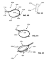
- FIG. 49 is a plan view of a portion of a stone removal assistance device according to still another embodiment of the present disclosure.
- FIG. 50 is a cutaway view of the device of FIG. 49 .
- FIG. 51 is an additional plan view of the device of FIG. 49 .
- FIG. 52 is a plan view of a portion of a stone removal assistance device according to another embodiment of the present disclosure.
- the present disclosure generally relates to devices and methods for the retrieval of material from the body of a patient.
- the devices and methods may permit eased capture of material and may prevent damage to the lining of the body tract in which the material resides.
- Features of the present disclosure may also be advantageous in clinical situations where the material must be released and the device must be withdrawn from the body. Examples of devices according to the invention are shown on figures 2 to 9 and 46 to 48 .
- FIG. 1 is an exemplary cross-sectional view of a stone removal assistance device 100 including a retrieval assembly 120 in an extended and expanded position according to an illustrative embodiment of the invention.
- the device 100 may include a handle 102, a sheath 310, and a retrieval assembly 120 moveable in a lumen 305 of the sheath 310.
- the handle 102, the sheath 310, and the retrieval assembly 120 illustrated in FIG. 1 are not shown in their correct size or proportion to each other, and the sheath 310 may typically be much longer than the handle 102 or the retrieval assembly 120 to allow insertion into a body cavity, canal, or tract.
- the sheath 310 may be dimensioned based on the requirements of the application of the sheath 310 within the body. For example, for urological applications, the sheath 310 may be of a length capable of extending into, for example, any upper calyx of the bladder of a patient.
- the sheath 310 may be made of commonly available materials that provide sufficient strength and flexibility for adequate operation, but which are soft enough to avoid trauma or irritation to the tract or duct in which sheath 310 is deployed.
- Materials that may commonly be used to form sheath 310 include polyethylene, nylons, polyether block amide, polytetrafluoroethylene, urethanes, silicones, and other suitable polymer materials. The material used is preferably biocompatible and inert to body fluids.
- other features of the device 100 may include, for example, an elongate member 105, such as a cable, coil, shaft, cannula, tube, or mandril wire, that extends within the lumen 305 of the sheath 310, and at least one actuating mechanism 104.
- Operation of the actuating mechanism 104 may cause, for example, the retrieval assembly 120 to move into and out of the lumen 305 of the sheath 310.
- the actuating mechanism 104 may cause movement of the sheath 310 to advance the sheath 310 over a stationary retrieval assembly 120 and elongate member 105 to thereby enclose the retrieval assembly 120 within the sheath 310.
- the actuating mechanism 104 may be manipulated to slide the moveable sheath 310 back to expose the stationary retrieval assembly 120.
- an embodiment of a stone removal assistance device 100a may include an elongate member 105a that may be formed, for example, from a rod, cannula, or hollow tube.
- the elongate member 105a may include a proximal portion 135a and a retrieval assembly 120a.
- the proximal portion 135a and the retrieval assembly 120a may be formed from the same piece of material.
- the retrieval assembly 120a may include one or more legs 125a, and each of the legs 125a may have a free distal end 155a.
- one or more of the legs 125a may have an inner surface 220a, as shown in FIG. 2 , that may be smooth or textured. Such a textured inner surface 220a may assist in securing material when grasped in the retrieval assembly 120a. As will be described in greater detail below, any variety of texture useful in assisting in grasping material may be used.
- the legs 125a may be formed by, for example, laser cutting, chemical etching, or mechanically slicing the elongate member 105a.
- the elongate member 105a may be made of, for example, stainless steel (such as 300 and 400 series), cobalt chromium, nickel titanium, a thermoforming plastic, or other material that is biocompatible for surgical purposes. Other optional materials include, for example, polytetrafluoroethylene (“PTFE”), expanded polytetrafluoroethylene (“EPTFE”), or GoreTexTM.
- the elongate member 105a may be highly polished to improve laser light reflectivity and may include a polymer coated with a metal or a metal coated with a polymer. Thus, the elongate member 105a may have more than one layer. These same materials, or combinations thereof, may also be used to form the sheaths, elongate members, and/or other structures of the devices of the present disclosure.
- slots 122a may be cut into the elongate member 105a to define the legs 125a of the retrieval assembly 120a.
- the width of the slots 122a may be selected to control the width and/or mechanical behavior of the legs 125a.
- Stress relief features 121 a may be defined at proximal end of the legs 125a.
- a stress relief feature 121 a may be any shape that effectively reduces mechanical stress at the end of the associated slot and/or facilitates movement of the legs 125a neighboring the stress relief feature 121 a.
- a stress relief feature 121 a may be a hole at the proximal end of the slot 122a having a diameter that is greater than the width of the slot 122a.
- Flexibility features 111a may be cut into the proximal portion 135a to increase the flexibility of the proximal portion 135a when maneuvering the device 100a within the body of a patient.
- the flexibility features 111a may be positioned anywhere along a portion of the proximal portion 135a in order to impart a desired flexibility to portions of the device 100a.
- the cut for each flexibility feature 111 a may extend partially or completely through the wall of the elongate member 105a and may extend partially or completely around the circumference of the elongate member 105a.
- the flexibility feature 111a When extending completely around the circumference, the flexibility feature 111a may define a shape, such as the illustrated zigzag shape, to effectively interlock neighboring portions of the elongate member 105a that are separated by the cut.
- the flexibility features 111 a may improve the ability of the device 100a to pass through complex body structures.
- the retrieval assembly 120a may have a closed state ( FIG. 2 ) and an open state ( FIG. 3 ).
- the legs 125a of the retrieval assembly 120a may be arranged in any configuration useful for grasping stones or other material when in the open state.
- the shape of a leg 125a may be produced, for example, by cold working and/or hot working.
- Each of the legs 125a may have a similar shape, or alternatively, each of the legs 125a may have different shapes.
- the legs 125a may all be substantially straight and free at their distal ends 155a to permit grasping of an object in a tweezer-like manner. As shown in FIG.
- the retrieval assembly 120a may include legs 125a that curl back in the proximal direction when the retrieval assembly 120a is in an open state.
- the retrieval assembly 120a When in the open state, the retrieval assembly 120a may have a diameter, for example, of approximately 1.5 cm to approximately 2.5 cm.
- the shape and size of the retrieval assembly 120a may be selected to assist in capturing, for example, a calculi within the urinary tract of a patient.
- FIGS. 4, 5, and 6 illustrate the functioning of a stone removal assistance device 100b according to another embodiment of the present disclosure.
- FIG. 4 shows an embodiment of the device 100b in an open state.
- the device 100b may include an elongate member 105b and a sheath 310. This sheath 310 may be moveable relative to the elongate member 105b to facilitate opening and closing of the retrieval assembly 120b.
- the legs 125b may at least partially enter the sheath 310 and the retrieval assembly 120b may transition to the closed state as the sheath 310 is moved in the distal direction relative to the retrieval assembly 120b.
- FIG. 6 illustrates the retrieval assembly 120b in the fully closed, or collapsed, state with the legs 125b fully within a lumen 305 of the sheath 310.
- the device 100b may be inserted into a vessel V of a patient while the retrieval assembly 120b (not shown) is in a closed position.
- the vessel V may be, for example, a portion of the patient's urinary tract.
- the sheath 310 may be placed adjacent to a stone 200 in the vessel V to appropriately position the legs 125b of the retrieval assembly 120b next to the stone 200 while within the sheath 310.
- the distal end of sheath 310 is placed past, or distal to, the stone 200.
- the sheath 310 may then be retracted to permit the legs 125b to transition to the open state and capture the stone ( FIG. 8 ).
- the legs 125b may be moved in the proximal direction to assist in capturing the stone 200.
- the stone 200 may be a kidney stone, a struvite, a uric acid stone, a gallbladder stone, a cystine stone, or other solid deposit commonly removed from a body structure or vessel of a patient.
- Such stones 200 may contain various combinations of chemicals including, but not limited to, calcium, oxalate, and phosphate.
- the stone 200 may be of any size or shape, and could be, for example, flat, round, smooth, or jagged.
- FIGS. 7 and 8 show a stone 200 in close proximity to the vessel V, devices of the present disclosure may assist in the immobilization and removal of stones that are both impacted and free floating.
- the devices of the present disclosure may assist in manipulating, capturing, fragmenting, reducing the size of, and/or removing stones 200 of the type described above, the devices may also assist in manipulating, capturing, fragmenting, reducing the size of, and/or removing any other type of biological, foreign, and/or other matter from within the body of a patient.
- FIGS. 22-24 show an embodiment of a portion of a device 100j that includes an elongate member 105j and a grasping assembly 120j formed from a distal portion of the elongate member 105j.
- the grasping assembly 120j includes legs 125j that have a free end E and that are substantially straight when the grasping assembly 120j is in the open state. Particularly, legs 125j are curved slightly outward when in the open, unrestrained state.
- the legs 125j may be gradually collapsed to grasp and hold a stone 200 ( FIG. 25 ) by moving a sheath (not shown) at least partially over the grasping assembly 120j.
- the legs 125j may thus be operated in a tweezer-like manner.
- the legs 125j may be provided with at least one textured surface 220j to assist grasping of a material.
- Texture imparted to the surface 220j may be formed, for example, by cutting, etching, sand blasting, or by a variety of other known techniques. These techniques may create any desirable contact feature 215j such as, for example, serrations or pitting useful in gripping and controlling material such as a stone.
- the textured surface 220j may include teeth 215j.
- FIG. 25 illustrates a use of the device 100j of FIGS. 22-24 for laser lithotripsy.
- an optical fiber 130j may be moved through a lumen of the elongate member 105j until the end of the fiber 130j is appropriately positioned next to the stone 200. Laser light may then be directed toward the stone 200 to break up and/or dissolve the stone 200.
- a stone removal assistance device 100c includes a laser light component 130, such as an optical fiber, a cannula 110c defining a lumen 306c, and a retrieval assembly 120c including a leg 125c having a ramp portion 115c.
- the laser light component 130 may be directed along the lumen 306c of the cannula 110c and positioned adjacent to a stone 200 trapped by the device 100c.
- the ramp portion 115c may be shaped to direct the laser light component 130 toward the stone 200 when the laser light component 130 exits the lumen 306c of the cannula 110c.
- ramp portion 115c may comprise a portion of leg 125c raised or otherwise directed to an inward surface of leg 125c when leg 125c is in an open and/or curled state. In that way, ramp portion 115c may contact a distal end of laser light component 130 to deflect component 130 toward the stone 200. Laser light may then be directed upon the stone 200, for example, for laser lithotripsy.
- FIG. 10 shows another embodiment of a stone removal assistance device 100d.
- the device 100d includes a cannula 110d that defines a lumen 306d.
- the device 100d has a retrieval assembly 120d that includes two or more legs 125d. Part of the cannula 110d may be connected to one or more of the legs 125d to define the retrieval assembly 120d for trapping stones or other material in a patient's body.
- the cannula 110d and the legs 125d may cooperate to grasp a stone (not shown).
- the device 100d may include one or more tension members 122d, such as a thread, joined to the distal ends 155d of one or more of the legs 125d.
- FIG. 10 shows three such tension members 122d, one corresponding to each leg 125d.
- a single tension member 122d may attach to more than one leg 125d or all of the legs 125d. Pulling on the tension members 122d may provide control for grasping and/or releasing a stone.
- the tension members 122d may extend within the lumen 306d of the cannula 110d and may exit from an aperture 230d in the wall of the cannula 110d.
- tension members 122d may extend completely through cannula 110d and exit cannula 110d at a proximal most end. In operation, the tension members 122d may be released to permit the retrieval assembly 120d to extend and collapse as a sheath (not shown) is moved over the retrieval assembly 120d.
- FIGS. 11 and 12 show another embodiment of a stone removal assistance device 100e.
- the device 100e may include a substantially hollow proximal portion or cannula 110e, a retrieval assembly 120e including two or more legs 125e, and a distal end 127e that joins the two or more legs 125e together.
- the cannula 110e and the retrieval assembly 120e may be formed from a single piece of tubing.
- the device 100e may be mechanically similar to the device 100a of FIGS. 2 and 3 except that the slots 122e may not extend completely in the distal direction, thus forming distal end 127e.
- the device 100e may include a sheath 310 ( FIG. 12 ).
- the sheath 310 may include cutouts 311 to increase the flexibility of the sheath 310.
- the cutouts 311 may be substantially the same as the flexibility features 111 described above.
- the cannula 110e may include at least one flexibility feature 111e.
- the distal end 127e may be filled with, for example, epoxy or brazing material. Since the distal end may be formed from the hollow cannula 110e in some embodiments, the epoxy or brazing material may at least partially fill a hole defined by an inner diameter of the hollow cannula 110e.
- FIGS. 13-17 show another embodiment of a stone removal assistance device 100f.
- the device 100f includes a sheath 310, a cannula 110f that defines a lumen 306f, and a retrieval assembly 120f including four legs 125f joined in two pairs, each pair defining a loop.
- each leg 125f may include one or more contact features 215f, for example, on inward-facing surfaces, to assist in, for example, gripping a stone.
- the device 100f may further include at least one stress relief feature 121f defined at the proximal end of the legs 125f. As explained with respect to FIG.
- the stress relief features 121f may be any shape that effectively reduces mechanical stress at the end of the associated legs 125f and may facilitate movement of the legs 125f neighboring the stress relief feature 121f. As shown in FIG. 13 , the stress relief feature 121f may be a hole at the proximal end of legs 125f.
- FIGS. 14 and 15 show the retrieval assembly 120f in a closed state
- FIGS. 16 and 17 show the retrieval assembly 120f in an open state.
- the retrieval assembly 120f In its closed state, the retrieval assembly 120f may substantially conform to the interior dimensions of the sheath 310. In its open state, however, the retrieval assembly 120f may expand along its width as illustrated in FIG. 17 .
- the pair of loops comprising assembly 120f may separate radially from each other, as shown in FIG. 16 .
- FIG. 18 shows another embodiment of a stone removal assistance device 100g.
- the device 100g includes a cannula 110g that defines a lumen 306g and a retrieval assembly 120g.
- the retrieval assembly 120g is formed by cutting a single loop from the cannula 110g.
- the device 100g may also include a sheath (not shown).
- the single loop may be formed, for example, by first cutting two loops in a portion of the cannula 110g, similar to the two loops of the device 100f shown in FIG. 13 . A subsequent cut may detach one end of the loops from the remainder of the cannula 110g at location C, thus forming a single loop. Using the device 100f shown in FIG. 13 for illustrative purposes, cutting the cannula 110f at the location C (dashed line in FIG. 13 ) may detach the two loops while preserving the connection between their ends, thus forming a single, larger loop.
- the retrieval assembly 120g may also include netting 128g attached to the loop.
- Netting 128g may be any suitable, flexible, biocompatible fabric, weave, filter-like structure, cross-wire arrangement, or the like. Netting 128g may be provided throughout the entire loop or only part of the loop. The netting 128g may assist trapping stones and/or other material in the basket defined by the retrieval assembly 120g and/or may assist in acting as a backstop during laser lithotripsy.
- FIG. 19 shows a cross-section of a portion of another embodiment of a stone removal assistance device 100h.
- the device 100h includes an elongate member 105h, a cannula 110h, and a retrieval assembly 120h having one or more legs 125h.
- the cannula 110h and the one or more legs 125h of the retrieval assembly 120h may be cut from a single piece of cannula 110h.
- the cannula 110h may be attached to the elongate member 105h with an attachment means 191.
- the attachment means 191 may be, for example, a weldment, solder, epoxy, cyanoacrylate, or brazing material.
- the elongate member 105h may be hollow or solid and may be, for example, a mandrel formed from wire. In an embodiment where the elongate member 105h is hollow, the elongate member 105h may define at least one lumen 306h.
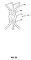
- FIG. 20 illustrates a further embodiment of a device 100i according to the present disclosure.
- the device 100i includes a cannula 110i and a retrieval assembly 120i formed from a single piece of cannula 110i.
- FIG. 21 is a cross-sectional view of the device illustrated in FIG. 20 , with the section indicated by the dashed line in FIG. 20 .
- the retrieval portion 120i includes two proximal legs 126i, six distal legs 125i, and a distal end portion 127i.
- the retrieval portion 120i may have a parachute-like shape and each proximal leg 126i may be integrally joined at one end with the cannula 110i, and at the other end with three of the distal legs 125i.
- the opposite end of each distal leg 125i may be connected to the distal end portion 127i.
- the proximal legs 126i may be longer or shorter than the distal legs 125i, and the proximal legs 126i may be wider than the distal legs 125i.
- the proximal legs 126i may be made by, for example, cutting two slots completely through the cannula 110i approximately 180 degrees apart. Any number of additional cuts may be made in between these initial cuts to obtain a corresponding number of distal legs 125i made from the proximal legs 126i. Variations in the number of proximal legs 126i and distal legs 125i, as well as their lengths, widths, and other dimensional features in alternative embodiments will be apparent to one of ordinary skill in the retrieval basket arts.
- the retrieval portion 120i When used in cooperation with a sheath (not shown), the retrieval portion 120i may assume various configurations to assist capture and/or release of a material or stone in a patient's body. For example, the retrieval portion 120i may be extended completely out of the sheath to permit a fully open state. A stone (not shown) may be captured, and the proximal legs 126i may be covered with the sheath to partially close the retrieval portion 120i to trap the stone between the distal legs 125i.
- a device including, for example, a basket made of shape memory material such as wire, may be used to immobilize a stone or other like material during, for example, lithotripsy.
- the basket of the device may form a backstop and may prevent the advancement of the stone into, for example, the ureter during lithotripsy.
- the backstop may also enable a user to increase the amount of energy supplied to the stone during the procedure.
- a device 100k may be placed into position past, above, or otherwise distal to a stone 200.
- a lithotripsy device (not shown) may then be used to break up the stone 200. With the device 100k in place, stone fragments may then be swept into the bladder where they may be passed.
- the basket 120k may be deployed by means of an actuation device such as, for example, a thumbtab (not shown) connected to a wire (not shown) that may be coaxial with an outer sheath 310 of the device 100k. The distal end of the coaxial wire may be attached to the proximal end 145 of the basket 120k.
- FIGS. 9 , 26 , and 29 illustrate different embodiments of a deployed backstop within the body of a patient.
- the basket 120k may expand distal the stone 200 to span substantially the entire passage 140 of the body in which the device 100k is used.
- Basket 120k of this embodiment may assume an umbrella-like or mushroom-like shape when opened.
- the basket 120k may include four legs 125k and in some embodiments may include as many as eight legs 125k.
- FIG. 27 illustrates an end view of a four-leg embodiment of the device 100k of FIG. 26 .
- the legs 125k may be substantially evenly spaced and each leg 125k may be approximately 90 degrees apart from the closest adjacent leg.
- the legs 125k may also be substantially evenly spaced.
- FIG. 28 shows an elevation view of an eight-legged embodiment.
- the basket 120k may include netting 128k.
- the netting 128k may be made of, for example, shape memory wire or any other netting, fabric, or other like material known in the art.
- FIG. 29 illustrates another embodiment of a stone removal assistance device 100l.
- the basket 120l may be made of a single piece of shape memory wire.
- the basket 120l may be substantially curled and/or spiral-shaped and may expand distal a stone 200 to span substantially the entire passage of the body 140 in which the device 100l is used, or less than the passage of body 140.
- An instrument useful in reducing the size of a stone such as, for example, a laser light component 130, may be used in conjunction with the device 100l and act on the stone 200 while external to the device 100l.
- laser light component 130 may extend through a lumen 305 of sheath 310 to reach and act on stone 200.
- the device 100l may prevent the migration of the stone 200 while the stone is acted on.
- the tip 127I of the basket 120l may be, for example, dulled, rounded, or otherwise have an atraumatic shape or surface texture.
- the device 100l may include a handle (not shown) having an actuating mechanism (not shown).
- the retrieval assembly 120l may be deployed above the stone 200 by manipulating the actuating mechanism toward the distal end of the device 100l and thereby urging the retrieval assembly 120l at least partially beyond the lumen 305 of the sheath 310.
- the actuating mechanism may be operatively connected to a proximal end of an elongate member (not shown) of the device 100l to facilitate movement of the retrieval assembly 120l.
- the elongate member may be coaxial with the sheath 310.
- FIG. 31 shows another device according to an embodiment of the present disclosure that may immobilize a stone during laser lithotripsy and retrieve stone fragments after the stone reduction processes.
- the device 100m may include a plurality of preformed basket legs 125m.
- the distal ends 155m of the basket legs 125m may be fixed to the distal end of the sheath 310 by any conventional attachment means known in the art such as, for example, crimping, soldering, or adhesives.
- FIG. 32 is a cross-sectional view of the distal end 155m of the device 100m illustrating a crimped connection.
- a crimp ring 162m may be used to secure the legs 125m to the sheath 310.
- the legs 125m may be attached to an external surface of the sheath 310.
- the crimping ring 162m may be external to the sheath 310 or may be omitted.
- FIGS. 31-33 illustrate exemplary baskets 120m having four legs 125m, other embodiments of the device 100m may include more or less than four legs.
- the basket legs 125m may be located in close proximity to the outside surface of the sheath 310, and the proximal ends 160m of the legs 125m may pass through ports 165m located along the sheath 310 and attach to a collar 170m within the sheath 310.
- the collar 170m may be attached to a push rod 175m or any other flexible elongate member extending through the sheath 310 and translating longitudinally relative to sheath 310 for activation of the basket 120m.
- the push rod 175m may be an elongate actuation member.
- the legs 125m of the basket 120m may be urged through ports 165m and may expand to their preformed shape.
- An expanded basket 120m of the current embodiment is shown in FIG. 33 .
- the legs 125m of the basket 120m may be made of any shape memory material or alloy known in the art such as, for example, stainless steel, nitinol, plastics, composites, or shape memory plastics.
- the legs 125m may be of any preformed shape or configuration known in the art such as, for example, substantially semicircular ( FIG. 34 ), substantially semiovular ( FIG. 35 ), or substantially semiheart-shaped ( FIG. 36 ).
- the push rod 175n may be a hollow tube that is coaxial with the sheath 310.
- the proximal end 160n of each of the legs 125n may be connected to the push rod 175n by any connection means known in the art.
- the proximal end 160n of the legs 125n may be welded, soldered, crimped, or otherwise fixed to the push rod 175n.
- the distal end (not shown) of the legs 125n may be connected to the distal end of the sheath 310.
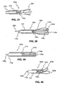
- a central stabilizing rod 180o may be disposed within a hollow push rod 175o and may extend substantially the length of the device 100o.
- the push rod 175o and the stabilizing rod 180o may be made of any materials known in the art.
- the push rod 175o may be, for example, a flexible metal wire.
- the push rod 175o may be moveable independent of the stabilizing rod 180o within the sheath 310 of the device 100o, such as the distal end of sheath 310.
- the stabilizing rod 180o may be fixed to at least a portion of the device 100o or, alternatively, may be unattached to the device 100o.
- a proximal end 160o of each of the legs 125o may be fixed to the distal end of the push rod 175o.
- FIG. 38 shows the legs 125o as attached to an inner surface of the push rod 175o, in other embodiments, the legs 125o may be fixed to an outer surface of the push rod 175o.
- the legs 125o may be fixed thereto by any conventional means known in the art such as, for example, welding, soldering, crimping, or adhering.
- the distal ends 155o of the basket legs 125o may be attached to the distal end of the stabilizing rod 180o.
- a connector 164o may connect the legs 125o to the stabilizing rod 180o.
- the connector 164o may be any conventional junction means, such as a crimp ring.
- the legs 125o may be deployed by advancing the push rod 175o toward the distal end 150o of the device 100o.
- the sheath 310 may be omitted.
- the sheath 310 may include a number of ports 165o and at least a portion of the legs 125o may pass through the ports 165o as the push rod 175o is advanced toward the distal end 150o of the device 100o.
- the basket legs 125p of a device 100p may be entirely within the sheath 310 when the basket is in its collapsed position, and the ports located along the sheath 310 may be omitted, as shown in FIG. 39 .
- at least a portion of the legs 125p may extend from the distal end of the sheath 310 as the push rod 175p is advanced.
- the distal ends 155p of the legs 125p may be connected to the stabilizing rod 180p by a connector 164p as described above.
- FIG. 40 illustrates a partially expanded basket 120p of the device 100p.
- the device may include more than one basket for immobilizing and/or capturing a stone.
- a multibasket device 100q may include a distal basket 185q and a proximal basket 190q.
- the distal basket 185q may be collapsed when withdrawn within a lumen 305 of the sheath 310 ( FIG. 41 ) and may be expanded when extended at least partially outside of the lumen 305 of the sheath 310 ( FIG. 42 ).
- the proximal end 160q of the legs 125q of the distal basket 185q may be fixed to the distal end of the push rod 175q.
- the distal basket 185q may be expanded ( FIG. 42 ) or collapsed ( FIG. 41 ) by actuating the push rod 175q toward the distal or proximal end of the device 100q relative to sheath 310, respectively.
- the distal basket 185q may include at least two legs 125q, and as shown in FIGS. 41 and 42 , in some embodiments, the distal basket 185q may include four legs 125q, each connected at their proximal end to the distal end of the push rod 175q.
- Each of the legs 125q of the distal basket 185q may be made of, for example, shape memory material.
- the proximal basket 190q may also include at least two legs 125q.
- the distal end 155q of each leg 125q of the proximal basket 190q may be fixedly attached to the sheath 310.
- FIGS. 41 and 42 illustrate the legs 125q of the proximal basket 190q being connected to an inner surface of the sheath 310, in other embodiments, the legs 125q may be connected to an outer surface of the sheath 310 ( FIG. 43 ).
- the sheath may include a number of proximal ports 165q and distal ports 166q.
- each leg 125q may be disposed within a corresponding proximal port 165q and a different portion of each leg 125q may be disposed within a corresponding distal port 166q. At least a portion of the legs 125q may extend and retract through the proximal ports 165 as the proximal basket 190q is opened and closed, respectively. In embodiments where the legs 125q of the proximal basket 190q are connected to an outer surface of the sheath 310 ( FIG. 43 ), the distal ports 166q may be omitted. As described above, the legs 125q may be fixed to the sheath 310 by any conventional means such as, for example, welding, soldering, crimping, or adhering.
- the proximal end 160q of the proximal basket legs 125q may be fixed to the push rod 175q by the same or similar conventional means.
- the push rod 175q may be advanced toward the distal end 150q of the device 100q relative to sheath 310. Advancing the push rod 175q in this direction may also at least partially expand the distal basket 185q as basket 185q exits the distal end of sheath 310. Because at least a portion of each basket 185q, 190q is attached to the push rod 175q, the baskets 185q, 190q may be expanded and collapsed substantially in unison by advancing and withdrawing the push rod 175q, respectively.
- the device 100q may be capable of immobilizing a stone both distally and proximally. To do so, the device 100q in the undeployed state shown in FIG. 41 may be advanced until the distal end of the sheath 310 is distal the stone. The distal basket 185q and the proximal basket 190q may then be expanded by urging the push rod 175q in the distal direction and thereby trapping the stone between the two expanded baskets 185q, 190q.
- proximal and distal baskets may be individually expandable and collapsible.
- a multibasket device 100r may include a proximal basket 190r and a distal basket 185r.
- the proximal end 160r of the legs 125r of the distal basket 185r may be connected to a push rod 175r disposed within a lumen 305 of the sheath 310. This connection may be facilitated by any of the connection means discussed above.
- Advancing the push rod 175r toward the distal end 150r of the device 100r relative to sheath 310 may urge the distal basket 185r out from within the lumen 305 of the sheath 310, thereby at least partially expanding the distal basket 185r.
- Moving the push rod 175r in a direction toward the proximal end 195r of the device 100r relative to sheath 310 may withdraw the distal basket 185r into the lumen 305 and may at least partially collapse the distal basket 185r.
- An exemplary collapsed position of the distal basket 185r is illustrated in FIG. 43 and an exemplary expanded position of the basket 185r is shown in FIGS. 44 and 45 .
- the proximal basket 190r may include at least two legs 125r.
- a distal end 155r of each leg 125r may be fixedly attached to the outer surface of the sheath 310, as shown in FIG. 43 , or attached to an inner surface of sheath 310, like that shown in FIGS. 41 and 42 .
- a proximal end 160r of each leg 125r may be fixedly attached to a hollow tube 205r disposed within the lumen 305 of the sheath 310.
- the hollow tube 205r may be an extending member or any other like device known in the art.
- the push rod 175r may be disposed within the tube 205r such that the push rod 175r and the tube 205r are independently moveable.
- the tube 205r may be made of any material known in the art and may be rigid enough to assist in expanding and collapsing the proximal basket 190r within, for example, the urinary tract of a patient, yet flexible enough to traverse the anatomy. These materials may be similar to or the same as the materials of the push rod 175r. As shown in FIG.
- At least a portion of the legs 125r of the proximal basket 190r may extend substantially along the outer surface of the sheath 310 and at least a portion of the legs 125r may be disposed within the lumen 305.
- a portion of the legs 125r may exit the lumen 305 through one or more ports 165 defined by the sheath 310, as shown in FIG. 45 .
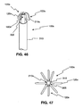
- Device 100s may include at least three wires 125s fixedly attached to a distal end of a shaft 210s.
- the wires 125s may be substantially flexible and may be made from any material known in the art such as, for example, stainless steel, nitinol, or a combination thereof.
- the shaft 210s may be substantially flexible, but may be rigid enough to urge the wires 125s out from a distal end of a sheath 310 when the device 100s is disposed within a tightly constrained area within the body of the patient.
- the shaft 210s may be made from materials similar to or the same as the wires 125s.
- the sheath 310 may be substantially flexible, substantially hollow, and may define at least one lumen 305.
- the sheath 310 may be formed from any suitable biocompatible material known in the art, such as those mentioned above.
- the sheath 310 may also be a metal coated with a polymer.
- the sheath 310 of the present embodiment may have an outer diameter in the range of approximately 0.013 inches to approximately 1.00 inches, and the corresponding device length may be in the range of approximately 50 centimeters to approximately 200 centimeters.
- the wires 125s may be spaced substantially evenly about the shaft 210s and may have any cross-sectional shape known in the art such as, for example, triangular, circular, square, rectangular, or trapezoidal. Each wire 125s may have the same cross-sectional shape, or each wire 125s may have a different shape depending on the requirements of the application.
- the proximal ends 160s of the wires 125s may be connected to the distal end of the shaft 210s by any of the conventional attachment means discussed above. Alternatively, in some embodiments, the wires 125s may be formed from the shaft 210s itself.
- the wires 125s may be formed by chemically etching, laser cutting, mechanically cutting, or otherwise modifying the shaft 210s. As a result of being formed from the shaft 210s, the wires 125s may have a cross-section that substantially corresponds to a portion of a cross-section of the shaft 210s. Regardless of whether the wires 125s are connected to or formed from the shaft 210s, each wire 125s may have a free distal end 155s, as shown in FIG. 46 .
- the wires 125s may also be disposed therein in a substantially straight, collapsed position. As the shaft 210s is moved toward the distal end of the sheath 310, at least a portion of the wires 125s may exit the distal end of the sheath 310.
- the wires 125s may be formed of shape memory material such that upon at least partially exiting the sheath 310, the wires 125s may form a basket having any desirable shape known in the art. For example, as illustrated in FIG. 46 , the wires 125s may form a substantially umbrella-shaped basket 120s.
- a fully open basket 120s in this configuration may have a diameter in the range of approximately 0.026 inches to approximately 2.00 inches.
- the corresponding wires 125s of such a basket 120s may have a length in the range of approximately 0.013 inches to approximately 1.00 inches.
- the basket 120s may substantially conform to the diameter of the body passage in which the device 100s is disposed.
- the device 100s may be positioned, and the basket 120s may be expanded, distal a stone to limit the stone's mobility during stone reduction and/or removal procedures such as, for example, laser lithotripsy.
- the device 100s may also be used to sweep a stone out from within the body of the patient.
- the unattached distal ends 155s of the wires 125s may be rounded, bent, folded, dulled, or otherwise shaped so as not to cause trauma to the body of the patient during use.
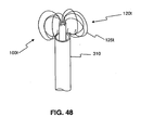
- the basket 120t may include legs that are substantially round or circular in an expanded, deployed position.
- the basket 120t may be expanded by manipulating the sheath 310 of the device 100t in a proximal direction. As the sheath 310 is retracted, the wires 125t may curl backwards in the proximal direction, thereby expanding the basket 120t.
- the expanded basket 120t may be useful in isolating, manipulating, and/or removing stones from the body of the patient.
- the basket 120t may be collapsed by manipulating the sheath 310 in the distal direction. As the sheath 310 passes over the wires 125t, the sheath 310 may force the wires 125t to straighten to facilitate entrance into a distal end of the sheath 310.
- embodiments of the present disclosure relate to devices that include an end effector, such as a basket or snare, made from a single piece of tube or cannula.
- an end effector such as a basket or snare
- Such configurations may eliminate the need to join separate wires at the base and/or tip of the end effector with weldments, crimped sections, soldered sections, over-cannulas, or other conventional means and may, thus, reduce the overall size of the device.
- such devices may include a sheath to facilitate the opening and closing of the basket.
- such embodiments of devices may be particularly useful in, for example, capturing, immobilizing, removing, and/or reducing the size of gallstones or other like foreign objects and may include a basket having any number of legs useful in, for example, isolating, manipulating, removing, or reducing the size of a stone.
- the device may be a cautery device useful in, for example, cauterizing and/or removing cessile or low-profile polyps or other like biological material.
- a basket 120w may include a continuous loop defined by two legs 125w and a distal end 127w. Basket 120w, therefore, is shaped like a snare device.
- the legs 125w of the loop may be formed by, for example, laser cutting at least a portion of the cannula 110w.
- the width, shape, and corresponding mechanical characteristics of the legs 125w may be determined by at least the size and configuration of these cuts.
- the embodiments shown in FIGS. 49-52 illustrate legs 125w formed through substantially longitudinal cuts, in other embodiments, the legs may be formed by laser cutting the cannula in any advantageous configuration.
- the legs may be formed by cutting the cannula in a substantially spiral configuration. Such cuts may result in a substantially helical basket (not shown).
- the legs 125w may further include one or more contact features 215w ( FIG. 50 ) located on an inner surface 220w of each leg 125w.
- the contact features 215w may improve the ability of each leg 125w to grip and/or reduce the size of a stone, polyp, or other object within the body of the patient and may be, for example, teeth, serrations, spikes, or any other conventional geometry useful in aiding in lithotripsy by grasping a stone.
- the contact features 215w may be formed of at least one layer of the cannula 110w by laser cutting and/or chemically etching the inner surface 220w of the legs 125w.
- At least one contact feature 215w may be connected to an inner surface 220w of one or more of the legs 125w, for example, at the distal tip 127w ( FIG. 49 ) of the basket 120w.
- the contact feature 215w may be connected to the inner surface 220w by, for example, soldering, welding, or any other conventional means.
- the contact feature 215w may be a spike 216w, as shown in FIG. 49 .
- the spike 216w an aid in immobilizing a stone during lithoptripsy.
- the cannula 110w may be made from any of the material mentioned above, and the mechanical characteristics of the legs may also result from the cannula material.
- the cannula 110w may be made from Elgiloy, stainless steel (400 series), nitinol, or a combination thereof.
- the cannula 110w may be a multilayered cannula consisting of, for example, an inner layer of nitinol and an outer layer of stainless steel. Such multilayered cannulas may increase the strength, dilation force, and overall stone reduction and/or removal capabilities of the device 100w.
- the cannula 110w may also be hollow and may define at least one lumen 306w.
- the lumen 306w may be useful in delivering fluid to and/or removing fluid from a treatment site within the body of the patient, such as a location within the body of the patient in the vicinity of a stone, polyp, or other like object.
- the lumen 306w may also be sized and shaped to accept a guidewire (not shown).
- the device may be passed over a guidewire to a treatment site.
- the lumen 306w may be sized and shaped to accept, for example, a therapeutic or diagnostic device 225, such as an electrohemostasis catheter, an injection needle, or other like device.
- a therapeutic or diagnostic device 225 such as an electrohemostasis catheter, an injection needle, or other like device.
- An injection needle may be capable of injecting, for example, saline or other like substances into a polyp to raise the polyp for rapid snaring with the device 100w.
- a section of the cannula 110w may include one or more flexibility features 111w.
- the flexibility features 111w may be positioned in any location along the cannula 110w to assist in improving the flexibility of the device 100w during cannulation.
- the flexibility features 111w may be, for example, spiral, helical, triangular, D-shaped, dove-tail shaped, or any other shape known in the art, and may be, for example, laser cut into at least one layer of the cannula 1110w.
- Basket 125w may be connected to a source of cautery current and used as an electrocautery device to remove, for example, a polyp or other tissue, similar to a snare device.
- the basket 120w may include at least two legs 125w and may include any number of additional legs 126w useful in, for example, capturing a polyp after cauterization.
- the additional legs 126w may be formed by laser cutting cannula 110w and/or at least one of the legs 125w of the basket 120w and may form, for example, a net or scoop-type geometry.
- the devices described above may be used, for example, in urological procedures to, for example, remove stones, polyps, or other materials from anywhere in the urinary system.
- the devices include baskets having distal ends that are more flexible and/or less likely to cause damage as compared to the distal ends of some prior devices.
- the baskets of the present disclosure may be quickly manufactured by, for example, preparing a precut, preformed component from a single piece of material, which is then attached to a mandrel wire.
Abstract
Description
- Embodiments of this invention generally relate to medical devices, and, more particularly, to medical devices for assisting in the removal of stones or other biological and/or foreign material from the body of a patient.
- A surgical retrieval device may be used, for example, to retrieve calculi from a body. The device may be used through an endoscope or a laparoscope, or it may be used without the aid of an endoscope or a laparoscope.
- One type of surgical retrieval device has a sheath and a basket formed from wires. The basket is moveable in and out of the sheath. The basket may be collapsed within the sheath to achieve a reduced diameter profile. The basket may be opened when it extends beyond the distal end of the sheath.
- Some retrieval devices include wires grouped together inside a cannula with the wires joined via soldering or welding to form a ball. Manufacturing of such devices may be costly and time consuming. Other devices have wires that are twisted and/or knotted together to eliminate a welded or soldered tip at the distal end of a basket. The tips of such devices may hinder access to calculi and may increase the possibility of tissue damage.
Examples of devices according to the prior art are disclosed inUS 5520697 ,DE 19722429 ,WO 01/97699 US 4811735 ,US 4174715 andUS 5944728 .
US 2004/054377 discloses a device according to the preamble of claim 1. - The medical device according to the invention is defined in claim 1.
In accordance with one aspect of the present disclosure, a medical device includes an elongate member and a retrieval assembly extending distally from the elongate member and formed from a same piece of material as the elongate member. The retrieval assembly is formed by removing at least a portion of the same piece of material. In some embodiments, the same piece of material is a hollow tube. The retrieval assembly further includes at least one leg. In some embodiments, the device includes an optical fiber extending through a lumen defined by the tube, and the at least one leg may include a ramp portion to assist in positioning the optical fiber. - In another embodiment, the device includes a sheath defining a lumen, the retrieval assembly having a collapsed state in which the retrieval assembly is substantially disposed within the lumen of the sheath, and an expanded state in which the retrieval assembly is substantially outside of the lumen of the sheath. The sheath defines at least one cutout to alter the flexibility of the sheath. The retrieval assembly comprises a plurality of legs, each .of the plurality of legs including a free distal end. In such an embodiment of the device, the plurality of legs are configured to transition from a substantially straight configuration when the retrieval assembly is in the collapsed state to a substantially curled configuration when the retrieval assembly is in the expanded state. Each of the plurality of legs, when in the substantially curled configuration, is curled back towards a proximal end of the device. The plurality of legs are configured to contact a biologic or foreign material in the substantially curled configuration to assist in removing the biologic or foreign material. The plurality of legs are configured to contact the biologic or foreign material as each free distal end is brought together by advancing the sheath toward the free distal ends. Each of the free distal ends includes at least one textured surface to assist in grasping the biologic or foreign material. In some embodiments, the elongate member defines at least one lumen. An optical fiber is disposed within the at least one lumen of the elongate member.
- In other embodiments, at least one of the plurality of legs includes at least one textured surface to assist in grasping a material. In still other embodiments, the retrieval assembly further includes a plurality of legs and a tension member attached to each of the plurality of legs for manipulating a corresponding leg. Each tension member extends at least partially through a lumen defined by the elongate member. Each tension member is attached to a free end of the corresponding leg. Each tension member exits from an aperture defined by a side of the elongate member. In further embodiments, the elongate member defines at least one hole at a proximal end of the retrieval assembly, at least a portion of a proximal portion of the elongate member is removed to define corresponding interlocking portions, and the retrieval assembly further comprises a plurality of legs joined at a distal end. In an embodiment where the retrieval assembly further comprises a plurality of legs joined at a distal end, the device further includes a sheath defining a lumen, the retrieval assembly having a collapsed state in which the retrieval assembly is substantially disposed within the lumen of the sheath, and an expanded state in which the retrieval assembly is substantially outside of the lumen of the sheath.
- In other embodiments, the retrieval assembly comprises two opposing loops configured to move toward each other when the retrieval assembly transitions from an expanded state to a collapsed state. Each of the two opposing loops includes a textured inward facing surface to assist in grasping biologic or foreign material. The two opposing loops are joined to form a single continuous loop having a curved state with a free proximal end when the retrieval assembly is in an expanded state. The retrieval assembly further includes netting attached to at least a portion of the continuous loop. In still other embodiments, the retrieval assembly includes a plurality of proximal legs extending to a plurality of distal legs, the distal legs being joined at a distal end of the retrieval assembly. The plurality of proximal legs includes a first proximal leg joining a proximal end of at least two of the plurality of distal legs, and a second proximal leg joining a proximal end of at least two other of the plurality of distal legs. The plurality of distal legs includes six legs. The retrieval assembly includes a continuous loop. The same piece of material is hollow and defines at least one lumen. The continuous loop includes a plurality of teeth. The distal end includes at least one spike. The retrieval assembly further includes a plurality of legs on only one side of the loop, each leg extending from a proximal end to a distal end of the loop.
- In another embodiment of the present disclosure, a medical device includes a basket made of shape memory material and comprising a plurality of legs and a netting, a distal end of a first leg of the plurality of legs being configured to curve away from a distal end of a second leg of the plurality of legs when the basket is in a substantially open position, and the netting being connected to a distal end of each of the plurality of legs and an elongate member connected to a proximal end of the basket and disposed within a lumen of a sheath, the basket having a collapsed state in which the basket is substantially disposed within the lumen of the sheath, and an expanded state in which the basket is substantially outside of the lumen of the sheath. In such an embodiment, the netting is made of shape memory material. The basket is configured to assume an umbrella-like shape in the expanded state to assist in immobilizing a stone. Each of the plurality of legs are substantially evenly spaced apart.
- In still another embodiment of the present disclosure, a medical device includes a basket made of shape memory material and comprising a substantially spiral-shaped leg and a free distal end curved toward a proximal end of the leg and an elongate member connected to a proximal end of the basket and disposed within a lumen of a sheath of the device, the basket having a collapsed state in which the basket is substantially disposed within the lumen of the sheath and an expanded state in which the basket is substantially outside of the lumen of the sheath. The basket includes a single leg.
- In a further embodiment of the present disclosure, a medical device includes a sheath defining a lumen, an elongate actuation member disposed within the lumen of the sheath and longitudinally moveable relative to the sheath, and a basket including a plurality of legs, a distal end of each of the plurality of legs being fixed to the sheath, a proximal end of each of the plurality of legs being fixed to the elongate actuation member, wherein movement of the elongate actuation member distally relative to the sheath expands the basket. The distal end of each of the plurality of legs is fixed a distal end of the sheath. The device includes a crimp ring configured to fixedly connect each of the plurality of legs to the sheath. The crimp ring fixedly connects each of the plurality of legs to an inner surface of the sheath. At least a portion of each of the plurality of legs extends proximate to an outside surface of the sheath when the basket is in a closed position. The sheath defines a plurality of ports along a length of the sheath, the ports configured to accept at least one of the plurality of legs. The number of the plurality of ports is equal to the number of the plurality of legs. Each of the plurality of legs is made of a shape memory material. The elongate actuation member is hollow and a proximal end of each of the plurality of legs is connected to a distal end of the elongate actuation member.
- In another embodiment of the present disclosure, a medical device includes a sheath defining a lumen, an elongate actuation member disposed within the lumen of the sheath and longitudinally moveable relative to the sheath, a stabilizing member at least partially disposed within a lumen of the elongate actuation member, the stabilizing member being longitudinally moveable relative to the elongate actuation member, and a basket including a plurality of legs, a distal end of each of the plurality of legs being coupled to the stabilizing member, a proximal end of each of the plurality of legs being coupled to the elongate actuation member, and at least a portion of each of the plurality of legs extending proximate to an outside surface of the sheath when the basket is in a closed position. The sheath defines a plurality of ports along a length of the sheath, the ports configured to accept at least one of the plurality of legs. The number of the plurality of ports is equal to the number of the plurality of legs. The basket is configured to transition between an expanded position and a collapsed position by manipulating the elongate actuation member relative to the stabilizing member.
- In still another embodiment of the present disclosure, a medical device includes a sheath defining a lumen, an elongate actuation member disposed within the lumen of the sheath and longitudinally moveable relative to the sheath, a stabilizing member at least partially disposed within the elongate actuation member and longitudinally moveable relative to the elongate actuation member within the lumen of the sheath, and a basket including a plurality of legs, a distal end of each of the plurality of legs being fixed to a distal end of the stabilizing member, a proximal end of each of the plurality of legs being fixed to the elongate actuation member, and each of the plurality of legs being substantially entirely disposed within the lumen of the sheath when the basket is in a closed position. At least a portion of the basket expands from a distal end of the sheath as the elongate actuation member is advanced toward the distal end of the sheath.
- In yet another embodiment of the present disclosure, a medical device includes a sheath defining a lumen, an elongate actuation member disposed within the lumen of the sheath and longitudinally moveable relative to the sheath, a proximal basket including a plurality of proximal legs, a distal end of each of the plurality of proximal legs being connected to a surface of the sheath, and a distal basket including a plurality of distal legs, a proximal end of each of the plurality of distal legs being connected to a distal end of the elongate actuation member. At least a portion of the basket expands from a distal end of the sheath as the elongate actuation member is advanced toward the distal end of the sheath.
- In still another embodiment of the present disclosure, a medical device includes a sheath defining a lumen, an elongate actuation member disposed within the lumen of the sheath and longitudinally moveable relative to the sheath, a proximal basket including a plurality of proximal legs, a distal end of each of the plurality of proximal legs being connected to a surface of the sheath, and a distal basket including a plurality of distal legs, a proximal end of each of the plurality of distal legs being connected to a distal end of the elongate actuation member. The surface of the sheath is an inner surface of the sheath. A proximal end of each of the plurality of proximal legs is connected to the elongate actuation member and the elongate actuation member is configured to manipulate at least a portion of the proximal basket. The sheath defines a plurality of ports configured to accept at least one of the plurality of proximal legs. In such a device, the number of the plurality of ports is equal to the number of the plurality of proximal legs. At least a portion of each of the plurality of proximal legs extends proximate to an outside surface of the sheath when the proximal basket is in a closed position. The proximal basket and the distal basket are configured to transition between respective expanded positions and collapsed positions substantially in unison. Such a device, also includes an extending member disposed within the at least one lumen of the sheath and defining an extending member lumen, the elongate actuation member being disposed within the extending member lumen. A proximal end of each of the plurality of proximal legs is connected to the extending member. The sheath defines a plurality of ports configured to accept at least one of the plurality of proximal legs. The number of the plurality of ports is equal to the number of the plurality of proximal legs. At least a portion of each of the plurality of proximal legs extends proximate to an outside surface of the sheath when the proximal basket is in a closed position. The proximal basket and the distal basket are independently maneuverable.
- In a further embodiment of the present disclosure, a medical device includes a sheath defining a lumen, a shaft disposed within the lumen and moveable relative to the lumen, and a retrieval assembly including a plurality of legs comprising a shape memory material, each of the plurality of legs having a proximal end fixedly attached to a distal end of the shaft, and a free distal end extending in a proximal direction beyond the distal end of the shaft when the retrieval assembly is in a substantially expanded position. Each of the plurality of legs is formed of the shaft. The retrieval assembly achieves the substantially expanded position as the sheath is moved in a proximal direction relative to the shaft. Each of the plurality of legs achieves a substantially circular shape when the retrieval assembly is in the substantially expanded position.
- In yet another embodiment of the present disclosure, a method of making a medical device includes providing an elongate member, and removing at least a portion of the elongate member to form a retrieval assembly, the retrieval assembly comprising at least two loops, each of the at least two loops having a proximal end integral with the elongate member. The method may further include forming a plurality of teeth on a surface of each of the at least two loops, removing at least a portion of a proximal portion of the elongate member to define corresponding interlocking portions, forming at least one hole at the proximal ends of the at least two loops, and detaching a portion of each of the at least two loops from the elongate member so as to form a single loop, the single loop having a free distal end and a proximal end that is connected to the elongate member. The at least two loops are connected only at the proximal ends. The method may further include providing a netting connected to at least a portion of the single loop.
- In another embodiment of the present disclosure, a method of making a medical device includes providing an elongate member and removing a portion of the elongate member to form a retrieval assembly, the retrieval assembly comprising at least two proximal legs extending to a plurality of distal legs, each of the plurality of distal legs being connected at a distal end portion of the retrieval assembly. The removing step includes first removing a portion of the elongate member to form two legs and then removing a portion of the two legs to form the two proximal legs and the plurality of distal legs. The elongate member defines at least one lumen.
- An exemplary method for removing a stone from a body includes providing a medical device comprising an elongate member and a retrieval assembly comprising a plurality of legs, a proximal end of each of the plurality of legs being connected to the elongate member and a distal end of each of the plurality of legs being connected to a corresponding tension member, positioning the retrieval assembly adjacent to the stone, expanding the retrieval assembly by releasing the tension members, and capturing the stone with the retrieval assembly. The capturing the stone further includes manipulating at least one of the tension members toward a proximal end of the device. The method may further include manipulating each of the legs independently via the corresponding tension members. Each of the tension members extends through a lumen of the elongate member.
- A further exemplary method for immobilizing a stone within a body includes providing a medical device comprising a sheath, an elongate actuation member disposed within a lumen of the sheath, a proximal basket including a plurality of proximal legs, and a distal basket including a plurality of distal legs, positioning a distal end of the sheath distal the stone, expanding the distal basket, and expanding the proximal basket. The expanding the distal basket includes manipulating the elongate actuation member in a distal direction. The expanding the proximal basket includes manipulating the elongate actuation member in a distal direction. The proximal basket and the distal basket expand in unison. The expanding the proximal basket includes manipulating an extending member disposed within the lumen of the sheath and moveable independent of the elongate actuation member. The proximal basket and the distal basket expand independently. The proximal basket is expanded proximal to the stone and the distal basket is expanded distal to the stone.
- Both the foregoing general description and the following detailed description are exemplary and explanatory only, and are not restrictive of the invention as claimed.
- In the drawings, like reference characters generally refer to the same parts throughout the different views. Also, the drawings are not necessarily to scale, emphasis instead generally being placed upon illustrating the principles of the invention.
-
FIG. 1 is a cross-sectional view of a stone removal assistance device according to an exemplary embodiment of the present disclosure. -
FIG. 2 is a side view of a portion of a stone removal assistance device according to an exemplary embodiment of the present disclosure. -
FIG. 2a is a cross-sectional view of the device illustrated inFIG. 2 . -
FIG. 3 is a partial view of the device ofFIG. 2 . -
FIG. 4 is a cross-sectional view of a portion of a stone removal assistance device according to another embodiment of the present disclosure. -
FIG. 5 is a cross-sectional view of the device ofFIG. 4 . -
FIG. 6 is another cross-sectional view of the device ofFIG. 4 . -
FIG. 7 is an operational view of the device ofFIG. 4 . -
FIG. 8 is another operational view of the device ofFIG. 4 . -
FIG. 9 is a cross-sectional view of a stone removal assistance device according to another embodiment of the present disclosure. -
FIG. 10 is a side view of a portion of a stone removal assistance device according to still another embodiment of the present disclosure. -
FIG. 11 is a side view of a portion of a stone removal assistance device according to yet another embodiment of the present disclosure. -
FIG. 12 is a plan view of the device ofFIG. 11 . -
FIG. 13 is a plan view of a portion of a stone removal assistance device according to a further embodiment of the present disclosure. -
FIG. 14 is a side view of the device ofFIG. 13 . -
FIG. 15 is a top view of the device ofFIG. 14 . -
FIG. 16 is another side view of the device ofFIG. 13 . -
FIG. 17 is a top view of the device ofFIG. 16 . -
FIG. 18 is a plan view of a portion of a stone removal assistance device according to a still further embodiment of the present disclosure. -
FIG. 19 is a cross-sectional view of a portion of a stone removal assistance device according to another embodiment of the present disclosure. -
FIG. 20 is a plan view of a portion of a stone removal assistance device according to still another embodiment of the present disclosure. -
FIG. 21 is a cross-sectional view of the device ofFIG. 20 . -
FIG. 22 is a plan view of a portion of a stone removal assistance device according to yet another embodiment of the present disclosure. -
FIG. 23 is a side view of the device ofFIG. 22 . -
FIG. 24 is a portion of a leg of the device ofFIG. 22 . -
FIG. 25 is an operational view of the device ofFIG. 22 . -
FIG. 26 is an operational view of a portion of a stone removal assistance device according to another embodiment of the present disclosure. -
FIG. 27 is an end view of the device ofFIG. 26 . -
FIG. 28 is a plan view of the device ofFIG. 26 . -
FIG. 29 is an operational view of a portion of a stone removal assistance device according to still another embodiment of the present disclosure. -
FIG. 30 is an end view of the device ofFIG. 29 . -
FIG. 31 is a partial cutaway view of a portion of a stone removal assistance device according to yet another embodiment of the present disclosure. -
FIG. 32 is a cross-sectional view of a distal end of the device ofFIG. 31 . -
FIG. 33 is an expanded basket of the device ofFIG. 31 . -
FIG. 34 is a leg for use in a stone removal assistance device. -
FIG. 35 is another leg for use in a stone removal assistance device. -
FIG. 36 is a further leg for use in a stone removal assistance device. -
FIG. 37 is a partial cutaway view of a portion of a stone removal assistance device according to a further embodiment of the present disclosure. -
FIG. 38 is a cross-sectional view of a portion of a stone removal assistance device according to a still further embodiment of the present disclosure. -
FIG. 39 is a cross-sectional view of a portion of a stone removal assistance device according to another embodiment of the present disclosure. -
FIG. 40 is a cross-sectional view of the device ofFIG. 39 . -
FIG. 41 is a cross-sectional view of a portion of a stone removal assistance device according to yet another embodiment of the present disclosure. -
FIG. 42 is a cross-sectional view of the device ofFIG. 41 . -
FIG. 43 is a cross-sectional view of a portion of a stone removal assistance device according to still another embodiment of the present disclosure. -
FIG. 44 is a side view of the device ofFIG. 43 . -
FIG. 45 is a further side view of the device ofFIG. 43 . -
FIG. 46 is a partial view of a stone removal assistance device according to an additional embodiment of the present disclosure. -
FIG. 47 is a top view of the device ofFIG. 46 . -
FIG. 48 is a partial view of a stone removal assistance device according to another embodiment of the present disclosure. -
FIG. 49 is a plan view of a portion of a stone removal assistance device according to still another embodiment of the present disclosure. -
FIG. 50 is a cutaway view of the device ofFIG. 49 . -
FIG. 51 is an additional plan view of the device ofFIG. 49 . -
FIG. 52 is a plan view of a portion of a stone removal assistance device according to another embodiment of the present disclosure. - The present disclosure generally relates to devices and methods for the retrieval of material from the body of a patient. The devices and methods may permit eased capture of material and may prevent damage to the lining of the body tract in which the material resides. Features of the present disclosure may also be advantageous in clinical situations where the material must be released and the device must be withdrawn from the body. Examples of devices according to the invention are shown on
figures 2 to 9 and 46 to 48 . -
FIG. 1 is an exemplary cross-sectional view of a stoneremoval assistance device 100 including aretrieval assembly 120 in an extended and expanded position according to an illustrative embodiment of the invention. Thedevice 100 may include ahandle 102, asheath 310, and aretrieval assembly 120 moveable in alumen 305 of thesheath 310. Thehandle 102, thesheath 310, and theretrieval assembly 120 illustrated inFIG. 1 are not shown in their correct size or proportion to each other, and thesheath 310 may typically be much longer than thehandle 102 or theretrieval assembly 120 to allow insertion into a body cavity, canal, or tract. Thesheath 310 may be dimensioned based on the requirements of the application of thesheath 310 within the body. For example, for urological applications, thesheath 310 may be of a length capable of extending into, for example, any upper calyx of the bladder of a patient. Thesheath 310 may be made of commonly available materials that provide sufficient strength and flexibility for adequate operation, but which are soft enough to avoid trauma or irritation to the tract or duct in whichsheath 310 is deployed. Materials that may commonly be used to formsheath 310 include polyethylene, nylons, polyether block amide, polytetrafluoroethylene, urethanes, silicones, and other suitable polymer materials. The material used is preferably biocompatible and inert to body fluids. - As shown in
FIG. 1 , other features of thedevice 100 may include, for example, anelongate member 105, such as a cable, coil, shaft, cannula, tube, or mandril wire, that extends within thelumen 305 of thesheath 310, and at least oneactuating mechanism 104. Operation of theactuating mechanism 104 may cause, for example, theretrieval assembly 120 to move into and out of thelumen 305 of thesheath 310. Alternatively, theactuating mechanism 104 may cause movement of thesheath 310 to advance thesheath 310 over astationary retrieval assembly 120 andelongate member 105 to thereby enclose theretrieval assembly 120 within thesheath 310. In such an embodiment, theactuating mechanism 104 may be manipulated to slide themoveable sheath 310 back to expose thestationary retrieval assembly 120. - Referring to
FIGS. 2 and 2a , an embodiment of a stoneremoval assistance device 100a may include anelongate member 105a that may be formed, for example, from a rod, cannula, or hollow tube. Theelongate member 105a may include aproximal portion 135a and aretrieval assembly 120a. Thus, theproximal portion 135a and theretrieval assembly 120a may be formed from the same piece of material. Theretrieval assembly 120a may include one ormore legs 125a, and each of thelegs 125a may have a freedistal end 155a. In addition, one or more of thelegs 125a may have aninner surface 220a, as shown inFIG. 2 , that may be smooth or textured. Such a texturedinner surface 220a may assist in securing material when grasped in theretrieval assembly 120a. As will be described in greater detail below, any variety of texture useful in assisting in grasping material may be used. - The
legs 125a may be formed by, for example, laser cutting, chemical etching, or mechanically slicing theelongate member 105a. Theelongate member 105a may be made of, for example, stainless steel (such as 300 and 400 series), cobalt chromium, nickel titanium, a thermoforming plastic, or other material that is biocompatible for surgical purposes. Other optional materials include, for example, polytetrafluoroethylene ("PTFE"), expanded polytetrafluoroethylene ("EPTFE"), or GoreTex™. Theelongate member 105a may be highly polished to improve laser light reflectivity and may include a polymer coated with a metal or a metal coated with a polymer. Thus, theelongate member 105a may have more than one layer. These same materials, or combinations thereof, may also be used to form the sheaths, elongate members, and/or other structures of the devices of the present disclosure. - With continued reference to
FIG. 2 ,slots 122a may be cut into theelongate member 105a to define thelegs 125a of theretrieval assembly 120a. The width of theslots 122a may be selected to control the width and/or mechanical behavior of thelegs 125a. Stress relief features 121 a may be defined at proximal end of thelegs 125a. Astress relief feature 121 a may be any shape that effectively reduces mechanical stress at the end of the associated slot and/or facilitates movement of thelegs 125a neighboring thestress relief feature 121 a. For example, in one embodiment, astress relief feature 121 a may be a hole at the proximal end of theslot 122a having a diameter that is greater than the width of theslot 122a. - Flexibility features 111a may be cut into the
proximal portion 135a to increase the flexibility of theproximal portion 135a when maneuvering thedevice 100a within the body of a patient. The flexibility features 111a may be positioned anywhere along a portion of theproximal portion 135a in order to impart a desired flexibility to portions of thedevice 100a. The cut for each flexibility feature 111 a may extend partially or completely through the wall of theelongate member 105a and may extend partially or completely around the circumference of theelongate member 105a. When extending completely around the circumference, theflexibility feature 111a may define a shape, such as the illustrated zigzag shape, to effectively interlock neighboring portions of theelongate member 105a that are separated by the cut. The flexibility features 111 a may improve the ability of thedevice 100a to pass through complex body structures. - The
retrieval assembly 120a may have a closed state (FIG. 2 ) and an open state (FIG. 3 ). Referring toFIG. 3 , thelegs 125a of theretrieval assembly 120a may be arranged in any configuration useful for grasping stones or other material when in the open state. The shape of aleg 125a may be produced, for example, by cold working and/or hot working. Each of thelegs 125a may have a similar shape, or alternatively, each of thelegs 125a may have different shapes. For example, thelegs 125a may all be substantially straight and free at theirdistal ends 155a to permit grasping of an object in a tweezer-like manner. As shown inFIG. 3 , theretrieval assembly 120a may includelegs 125a that curl back in the proximal direction when theretrieval assembly 120a is in an open state. When in the open state, theretrieval assembly 120a may have a diameter, for example, of approximately 1.5 cm to approximately 2.5 cm. The shape and size of theretrieval assembly 120a may be selected to assist in capturing, for example, a calculi within the urinary tract of a patient. -
FIGS. 4, 5, and 6 illustrate the functioning of a stoneremoval assistance device 100b according to another embodiment of the present disclosure.FIG. 4 shows an embodiment of thedevice 100b in an open state. In this embodiment, thedevice 100b may include anelongate member 105b and asheath 310. Thissheath 310 may be moveable relative to theelongate member 105b to facilitate opening and closing of theretrieval assembly 120b. - As shown in
FIG. 5 , thelegs 125b may at least partially enter thesheath 310 and theretrieval assembly 120b may transition to the closed state as thesheath 310 is moved in the distal direction relative to theretrieval assembly 120b.FIG. 6 illustrates theretrieval assembly 120b in the fully closed, or collapsed, state with thelegs 125b fully within alumen 305 of thesheath 310. - As shown in
FIG. 7 , thedevice 100b may be inserted into a vessel V of a patient while theretrieval assembly 120b (not shown) is in a closed position. The vessel V may be, for example, a portion of the patient's urinary tract. Thesheath 310 may be placed adjacent to astone 200 in the vessel V to appropriately position thelegs 125b of theretrieval assembly 120b next to thestone 200 while within thesheath 310. Preferably, the distal end ofsheath 310 is placed past, or distal to, thestone 200. Thesheath 310 may then be retracted to permit thelegs 125b to transition to the open state and capture the stone (FIG. 8 ). Thelegs 125b may be moved in the proximal direction to assist in capturing thestone 200. - The
stone 200 may be a kidney stone, a struvite, a uric acid stone, a gallbladder stone, a cystine stone, or other solid deposit commonly removed from a body structure or vessel of a patient.Such stones 200 may contain various combinations of chemicals including, but not limited to, calcium, oxalate, and phosphate. Thestone 200 may be of any size or shape, and could be, for example, flat, round, smooth, or jagged. AlthoughFIGS. 7 and 8 show astone 200 in close proximity to the vessel V, devices of the present disclosure may assist in the immobilization and removal of stones that are both impacted and free floating. Furthermore, while the devices of the present disclosure may assist in manipulating, capturing, fragmenting, reducing the size of, and/or removingstones 200 of the type described above, the devices may also assist in manipulating, capturing, fragmenting, reducing the size of, and/or removing any other type of biological, foreign, and/or other matter from within the body of a patient. - As another example of a stone removal assistance device formed from a single piece of material,
FIGS. 22-24 show an embodiment of a portion of adevice 100j that includes anelongate member 105j and a graspingassembly 120j formed from a distal portion of theelongate member 105j. The graspingassembly 120j includeslegs 125j that have a free end E and that are substantially straight when the graspingassembly 120j is in the open state. Particularly,legs 125j are curved slightly outward when in the open, unrestrained state. - The
legs 125j may be gradually collapsed to grasp and hold a stone 200 (FIG. 25 ) by moving a sheath (not shown) at least partially over the graspingassembly 120j. Thelegs 125j may thus be operated in a tweezer-like manner. - The
legs 125j may be provided with at least onetextured surface 220j to assist grasping of a material. Texture imparted to thesurface 220j may be formed, for example, by cutting, etching, sand blasting, or by a variety of other known techniques. These techniques may create anydesirable contact feature 215j such as, for example, serrations or pitting useful in gripping and controlling material such as a stone. As shown inFIG. 24 , in some embodiments, thetextured surface 220j may includeteeth 215j. -
FIG. 25 illustrates a use of thedevice 100j ofFIGS. 22-24 for laser lithotripsy. After capture of astone 200 by thelegs 125j, anoptical fiber 130j may be moved through a lumen of theelongate member 105j until the end of thefiber 130j is appropriately positioned next to thestone 200. Laser light may then be directed toward thestone 200 to break up and/or dissolve thestone 200. - Referring back to
FIG. 9 , another embodiment of a stoneremoval assistance device 100c according to principles of the present disclosure includes alaser light component 130, such as an optical fiber, acannula 110c defining alumen 306c, and aretrieval assembly 120c including aleg 125c having aramp portion 115c. Thelaser light component 130 may be directed along thelumen 306c of thecannula 110c and positioned adjacent to astone 200 trapped by thedevice 100c. Theramp portion 115c may be shaped to direct thelaser light component 130 toward thestone 200 when thelaser light component 130 exits thelumen 306c of thecannula 110c. For example,ramp portion 115c may comprise a portion ofleg 125c raised or otherwise directed to an inward surface ofleg 125c whenleg 125c is in an open and/or curled state. In that way,ramp portion 115c may contact a distal end oflaser light component 130 to deflectcomponent 130 toward thestone 200. Laser light may then be directed upon thestone 200, for example, for laser lithotripsy. -
FIG. 10 shows another embodiment of a stoneremoval assistance device 100d. Thedevice 100d includes acannula 110d that defines alumen 306d. Thedevice 100d has aretrieval assembly 120d that includes two ormore legs 125d. Part of thecannula 110d may be connected to one or more of thelegs 125d to define theretrieval assembly 120d for trapping stones or other material in a patient's body. Thecannula 110d and thelegs 125d may cooperate to grasp a stone (not shown). - The
device 100d may include one ormore tension members 122d, such as a thread, joined to the distal ends 155d of one or more of thelegs 125d.FIG. 10 shows threesuch tension members 122d, one corresponding to eachleg 125d. Alternatively, asingle tension member 122d may attach to more than oneleg 125d or all of thelegs 125d. Pulling on thetension members 122d may provide control for grasping and/or releasing a stone. Thetension members 122d may extend within thelumen 306d of thecannula 110d and may exit from anaperture 230d in the wall of thecannula 110d. Alternatively,tension members 122d may extend completely throughcannula 110d andexit cannula 110d at a proximal most end. In operation, thetension members 122d may be released to permit theretrieval assembly 120d to extend and collapse as a sheath (not shown) is moved over theretrieval assembly 120d. -
FIGS. 11 and12 show another embodiment of a stoneremoval assistance device 100e. Thedevice 100e may include a substantially hollow proximal portion orcannula 110e, aretrieval assembly 120e including two ormore legs 125e, and adistal end 127e that joins the two ormore legs 125e together. Thecannula 110e and theretrieval assembly 120e may be formed from a single piece of tubing. Thedevice 100e may be mechanically similar to thedevice 100a ofFIGS. 2 and3 except that theslots 122e may not extend completely in the distal direction, thus formingdistal end 127e. - In some embodiments, the
device 100e may include a sheath 310 (FIG. 12 ). In such embodiments, thesheath 310 may includecutouts 311 to increase the flexibility of thesheath 310. Thecutouts 311 may be substantially the same as the flexibility features 111 described above. As shown inFIG. 12 , thecannula 110e may include at least oneflexibility feature 111e. In addition, thedistal end 127e may be filled with, for example, epoxy or brazing material. Since the distal end may be formed from thehollow cannula 110e in some embodiments, the epoxy or brazing material may at least partially fill a hole defined by an inner diameter of thehollow cannula 110e. -
FIGS. 13-17 show another embodiment of a stoneremoval assistance device 100f. Thedevice 100f includes asheath 310, acannula 110f that defines alumen 306f, and aretrieval assembly 120f including fourlegs 125f joined in two pairs, each pair defining a loop. As described above with respect toFIGS. 22-25 , eachleg 125f may include one or more contact features 215f, for example, on inward-facing surfaces, to assist in, for example, gripping a stone. Thedevice 100f may further include at least onestress relief feature 121f defined at the proximal end of thelegs 125f. As explained with respect toFIG. 2 , the stress relief features 121f may be any shape that effectively reduces mechanical stress at the end of the associatedlegs 125f and may facilitate movement of thelegs 125f neighboring thestress relief feature 121f. As shown inFIG. 13 , thestress relief feature 121f may be a hole at the proximal end oflegs 125f. - As described above, a particular desired basket shape may be imparted to the
legs 125f by cutting and shaping fabrication steps.FIGS. 14 and 15 show theretrieval assembly 120f in a closed state, andFIGS. 16 and 17 show theretrieval assembly 120f in an open state. In its closed state, theretrieval assembly 120f may substantially conform to the interior dimensions of thesheath 310. In its open state, however, theretrieval assembly 120f may expand along its width as illustrated inFIG. 17 . Alternatively or additionally, the pair ofloops comprising assembly 120f may separate radially from each other, as shown inFIG. 16 . -
FIG. 18 shows another embodiment of a stoneremoval assistance device 100g. Thedevice 100g includes acannula 110g that defines alumen 306g and aretrieval assembly 120g. Theretrieval assembly 120g is formed by cutting a single loop from thecannula 110g. In some embodiments, thedevice 100g may also include a sheath (not shown). - The single loop may be formed, for example, by first cutting two loops in a portion of the
cannula 110g, similar to the two loops of thedevice 100f shown inFIG. 13 . A subsequent cut may detach one end of the loops from the remainder of thecannula 110g at location C, thus forming a single loop. Using thedevice 100f shown inFIG. 13 for illustrative purposes, cutting thecannula 110f at the location C (dashed line inFIG. 13 ) may detach the two loops while preserving the connection between their ends, thus forming a single, larger loop. - As shown in
FIG. 18 , theretrieval assembly 120g may also include netting 128g attached to the loop. Netting 128g may be any suitable, flexible, biocompatible fabric, weave, filter-like structure, cross-wire arrangement, or the like. Netting 128g may be provided throughout the entire loop or only part of the loop. Thenetting 128g may assist trapping stones and/or other material in the basket defined by theretrieval assembly 120g and/or may assist in acting as a backstop during laser lithotripsy. -
FIG. 19 shows a cross-section of a portion of another embodiment of a stoneremoval assistance device 100h. Thedevice 100h includes anelongate member 105h, acannula 110h, and aretrieval assembly 120h having one ormore legs 125h. Thecannula 110h and the one ormore legs 125h of theretrieval assembly 120h may be cut from a single piece ofcannula 110h. - The
cannula 110h may be attached to theelongate member 105h with an attachment means 191. The attachment means 191 may be, for example, a weldment, solder, epoxy, cyanoacrylate, or brazing material. Theelongate member 105h may be hollow or solid and may be, for example, a mandrel formed from wire. In an embodiment where theelongate member 105h is hollow, theelongate member 105h may define at least onelumen 306h. -
FIG. 20 illustrates a further embodiment of adevice 100i according to the present disclosure. Thedevice 100i includes acannula 110i and aretrieval assembly 120i formed from a single piece ofcannula 110i.FIG. 21 is a cross-sectional view of the device illustrated inFIG. 20 , with the section indicated by the dashed line inFIG. 20 . - The
retrieval portion 120i includes twoproximal legs 126i, sixdistal legs 125i, and adistal end portion 127i. Theretrieval portion 120i may have a parachute-like shape and eachproximal leg 126i may be integrally joined at one end with thecannula 110i, and at the other end with three of thedistal legs 125i. The opposite end of eachdistal leg 125i may be connected to thedistal end portion 127i. In some embodiments, theproximal legs 126i may be longer or shorter than thedistal legs 125i, and theproximal legs 126i may be wider than thedistal legs 125i. Theproximal legs 126i may be made by, for example, cutting two slots completely through thecannula 110i approximately 180 degrees apart. Any number of additional cuts may be made in between these initial cuts to obtain a corresponding number ofdistal legs 125i made from theproximal legs 126i. Variations in the number ofproximal legs 126i anddistal legs 125i, as well as their lengths, widths, and other dimensional features in alternative embodiments will be apparent to one of ordinary skill in the retrieval basket arts. - When used in cooperation with a sheath (not shown), the
retrieval portion 120i may assume various configurations to assist capture and/or release of a material or stone in a patient's body. For example, theretrieval portion 120i may be extended completely out of the sheath to permit a fully open state. A stone (not shown) may be captured, and theproximal legs 126i may be covered with the sheath to partially close theretrieval portion 120i to trap the stone between thedistal legs 125i. - In embodiments of the present disclosure, including various embodiments already described above and others to be described herein, a device including, for example, a basket made of shape memory material such as wire, may be used to immobilize a stone or other like material during, for example, lithotripsy. In some embodiments, the basket of the device may form a backstop and may prevent the advancement of the stone into, for example, the ureter during lithotripsy. The backstop may also enable a user to increase the amount of energy supplied to the stone during the procedure.
- As illustrated in
FIG. 26 , adevice 100k may be placed into position past, above, or otherwise distal to astone 200. A lithotripsy device (not shown) may then be used to break up thestone 200. With thedevice 100k in place, stone fragments may then be swept into the bladder where they may be passed. Once thedevice 100k is in position, thebasket 120k may be deployed by means of an actuation device such as, for example, a thumbtab (not shown) connected to a wire (not shown) that may be coaxial with anouter sheath 310 of thedevice 100k. The distal end of the coaxial wire may be attached to theproximal end 145 of thebasket 120k. When the thumbtab is moved in the direction of thedistal end 150 of thedevice 100k, thebasket 120k may be urged out of thesheath 310 to form a backstop.FIGS. 9 ,26 , and29 illustrate different embodiments of a deployed backstop within the body of a patient. - As shown in
FIG. 26 , in one embodiment thebasket 120k may expand distal thestone 200 to span substantially theentire passage 140 of the body in which thedevice 100k is used.Basket 120k of this embodiment may assume an umbrella-like or mushroom-like shape when opened. In such an embodiment, thebasket 120k may include fourlegs 125k and in some embodiments may include as many as eightlegs 125k. For example,FIG. 27 illustrates an end view of a four-leg embodiment of thedevice 100k ofFIG. 26 . In this embodiment, thelegs 125k may be substantially evenly spaced and eachleg 125k may be approximately 90 degrees apart from the closest adjacent leg. As illustrated by the dotted lines ofFIG. 27 , in an eight-legged embodiment, thelegs 125k may also be substantially evenly spaced. Other embodiments with different numbers of legs of various spacing may be suitable.FIG. 28 shows an elevation view of an eight-legged embodiment. As shown inFIGS. 26 and28 , thebasket 120k may include netting 128k. Thenetting 128k may be made of, for example, shape memory wire or any other netting, fabric, or other like material known in the art. -
FIG. 29 illustrates another embodiment of a stone removal assistance device 100l. In this embodiment, the basket 120l may be made of a single piece of shape memory wire. The basket 120l may be substantially curled and/or spiral-shaped and may expand distal astone 200 to span substantially the entire passage of thebody 140 in which the device 100l is used, or less than the passage ofbody 140. An instrument useful in reducing the size of a stone such as, for example, alaser light component 130, may be used in conjunction with the device 100l and act on thestone 200 while external to the device 100l. Alternatively,laser light component 130 may extend through alumen 305 ofsheath 310 to reach and act onstone 200. The device 100l may prevent the migration of thestone 200 while the stone is acted on.FIG. 30 shows an exemplary end view of the device 100l. As shown inFIGS. 29 and 30 , in some embodiments of the present disclosure, the tip 127I of the basket 120l may be, for example, dulled, rounded, or otherwise have an atraumatic shape or surface texture. - As described above with respect to
FIG. 1 , the device 100l may include a handle (not shown) having an actuating mechanism (not shown). Once the device 100l is positioned distal thestone 200, the retrieval assembly 120l may be deployed above thestone 200 by manipulating the actuating mechanism toward the distal end of the device 100l and thereby urging the retrieval assembly 120l at least partially beyond thelumen 305 of thesheath 310. The actuating mechanism may be operatively connected to a proximal end of an elongate member (not shown) of the device 100l to facilitate movement of the retrieval assembly 120l. The elongate member may be coaxial with thesheath 310. -
FIG. 31 shows another device according to an embodiment of the present disclosure that may immobilize a stone during laser lithotripsy and retrieve stone fragments after the stone reduction processes. As shown inFIG. 31 , thedevice 100m may include a plurality of preformedbasket legs 125m. The distal ends 155m of thebasket legs 125m may be fixed to the distal end of thesheath 310 by any conventional attachment means known in the art such as, for example, crimping, soldering, or adhesives.FIG. 32 is a cross-sectional view of thedistal end 155m of thedevice 100m illustrating a crimped connection. In such a connection, acrimp ring 162m, or other conventional crimping means, may be used to secure thelegs 125m to thesheath 310. Although shown as attached to an inner surface of thesheath 310, in other embodiments, thelegs 125m may be attached to an external surface of thesheath 310. In such an embodiment, the crimpingring 162m may be external to thesheath 310 or may be omitted. AlthoughFIGS. 31-33 illustrateexemplary baskets 120m having fourlegs 125m, other embodiments of thedevice 100m may include more or less than four legs. - As shown in
FIG. 31 , in a closed position, thebasket legs 125m may be located in close proximity to the outside surface of thesheath 310, and the proximal ends 160m of thelegs 125m may pass throughports 165m located along thesheath 310 and attach to acollar 170m within thesheath 310. Thecollar 170m may be attached to apush rod 175m or any other flexible elongate member extending through thesheath 310 and translating longitudinally relative tosheath 310 for activation of thebasket 120m. For example, in some embodiments, thepush rod 175m may be an elongate actuation member. When thepush rod 175m is advanced in a direction toward thedistal end 155m of thedevice 100m, thelegs 125m of thebasket 120m may be urged throughports 165m and may expand to their preformed shape. An expandedbasket 120m of the current embodiment is shown inFIG. 33 . - The
legs 125m of thebasket 120m may be made of any shape memory material or alloy known in the art such as, for example, stainless steel, nitinol, plastics, composites, or shape memory plastics. In addition, thelegs 125m may be of any preformed shape or configuration known in the art such as, for example, substantially semicircular (FIG. 34 ), substantially semiovular (FIG. 35 ), or substantially semiheart-shaped (FIG. 36 ). - As shown in
FIG. 37 , in another embodiment thepush rod 175n may be a hollow tube that is coaxial with thesheath 310. Theproximal end 160n of each of thelegs 125n may be connected to thepush rod 175n by any connection means known in the art. For example, in some embodiments, theproximal end 160n of thelegs 125n may be welded, soldered, crimped, or otherwise fixed to thepush rod 175n. As in thedevice 100m ofFIG. 31 , the distal end (not shown) of thelegs 125n may be connected to the distal end of thesheath 310. - As shown in
FIG. 38 , a central stabilizing rod 180o may be disposed within a hollow push rod 175o and may extend substantially the length of the device 100o. The push rod 175o and the stabilizing rod 180o may be made of any materials known in the art. The push rod 175o may be, for example, a flexible metal wire. The push rod 175o may be moveable independent of the stabilizing rod 180o within thesheath 310 of the device 100o, such as the distal end ofsheath 310. The stabilizing rod 180o may be fixed to at least a portion of the device 100o or, alternatively, may be unattached to the device 100o. - As shown in
FIG. 38 , a proximal end 160o of each of the legs 125o may be fixed to the distal end of the push rod 175o. AlthoughFIG. 38 shows the legs 125o as attached to an inner surface of the push rod 175o, in other embodiments, the legs 125o may be fixed to an outer surface of the push rod 175o. The legs 125o may be fixed thereto by any conventional means known in the art such as, for example, welding, soldering, crimping, or adhering. In this embodiment, the distal ends 155o of the basket legs 125o may be attached to the distal end of the stabilizing rod 180o. In some embodiments, a connector 164o may connect the legs 125o to the stabilizing rod 180o. The connector 164o may be any conventional junction means, such as a crimp ring. - As in the embodiments described above, the legs 125o may be deployed by advancing the push rod 175o toward the distal end 150o of the device 100o. In the embodiment of
FIG. 38 , thesheath 310 may be omitted. Alternatively, thesheath 310 may include a number of ports 165o and at least a portion of the legs 125o may pass through the ports 165o as the push rod 175o is advanced toward the distal end 150o of the device 100o. - In yet another exemplary embodiment, the
basket legs 125p of adevice 100p may be entirely within thesheath 310 when the basket is in its collapsed position, and the ports located along thesheath 310 may be omitted, as shown inFIG. 39 . In this embodiment, at least a portion of thelegs 125p may extend from the distal end of thesheath 310 as thepush rod 175p is advanced. The distal ends 155p of thelegs 125p may be connected to the stabilizingrod 180p by aconnector 164p as described above.FIG. 40 illustrates a partially expandedbasket 120p of thedevice 100p. - Moreover, as illustrated in
FIGS. 41-45 , in some embodiments of the present disclosure, the device may include more than one basket for immobilizing and/or capturing a stone. For example, as shown inFIGS. 41 and 42 , amultibasket device 100q may include adistal basket 185q and aproximal basket 190q. Thedistal basket 185q may be collapsed when withdrawn within alumen 305 of the sheath 310 (FIG. 41 ) and may be expanded when extended at least partially outside of thelumen 305 of the sheath 310 (FIG. 42 ). Theproximal end 160q of thelegs 125q of thedistal basket 185q may be fixed to the distal end of thepush rod 175q. Thedistal basket 185q may be expanded (FIG. 42 ) or collapsed (FIG. 41 ) by actuating thepush rod 175q toward the distal or proximal end of thedevice 100q relative tosheath 310, respectively. Thedistal basket 185q may include at least twolegs 125q, and as shown inFIGS. 41 and 42 , in some embodiments, thedistal basket 185q may include fourlegs 125q, each connected at their proximal end to the distal end of thepush rod 175q. Each of thelegs 125q of thedistal basket 185q may be made of, for example, shape memory material. - The
proximal basket 190q may also include at least twolegs 125q. Thedistal end 155q of eachleg 125q of theproximal basket 190q may be fixedly attached to thesheath 310. AlthoughFIGS. 41 and 42 illustrate thelegs 125q of theproximal basket 190q being connected to an inner surface of thesheath 310, in other embodiments, thelegs 125q may be connected to an outer surface of the sheath 310 (FIG. 43 ). In an embodiment where thelegs 125q of theproximal basket 190q are connected to an inner surface of the sheath 310 (FIGS. 41 and 42 ), the sheath may include a number ofproximal ports 165q anddistal ports 166q. In such an embodiment, at least a portion of eachleg 125q may be disposed within a correspondingproximal port 165q and a different portion of eachleg 125q may be disposed within a correspondingdistal port 166q. At least a portion of thelegs 125q may extend and retract through theproximal ports 165 as theproximal basket 190q is opened and closed, respectively. In embodiments where thelegs 125q of theproximal basket 190q are connected to an outer surface of the sheath 310 (FIG. 43 ), thedistal ports 166q may be omitted. As described above, thelegs 125q may be fixed to thesheath 310 by any conventional means such as, for example, welding, soldering, crimping, or adhering. - The
proximal end 160q of theproximal basket legs 125q may be fixed to thepush rod 175q by the same or similar conventional means. As shown inFIG. 42 , to expand theproximal basket 190q, thepush rod 175q may be advanced toward thedistal end 150q of thedevice 100q relative tosheath 310. Advancing thepush rod 175q in this direction may also at least partially expand thedistal basket 185q asbasket 185q exits the distal end ofsheath 310. Because at least a portion of eachbasket push rod 175q, thebaskets push rod 175q, respectively. In an embodiment in which thebaskets device 100q may be capable of immobilizing a stone both distally and proximally. To do so, thedevice 100q in the undeployed state shown inFIG. 41 may be advanced until the distal end of thesheath 310 is distal the stone. Thedistal basket 185q and theproximal basket 190q may then be expanded by urging thepush rod 175q in the distal direction and thereby trapping the stone between the two expandedbaskets - In other embodiments, the proximal and distal baskets may be individually expandable and collapsible. For example, as shown in
FIGS. 43-45 , amultibasket device 100r may include aproximal basket 190r and adistal basket 185r. Theproximal end 160r of thelegs 125r of thedistal basket 185r may be connected to apush rod 175r disposed within alumen 305 of thesheath 310. This connection may be facilitated by any of the connection means discussed above. Advancing thepush rod 175r toward thedistal end 150r of thedevice 100r relative tosheath 310 may urge thedistal basket 185r out from within thelumen 305 of thesheath 310, thereby at least partially expanding thedistal basket 185r. Moving thepush rod 175r in a direction toward theproximal end 195r of thedevice 100r relative tosheath 310 may withdraw thedistal basket 185r into thelumen 305 and may at least partially collapse thedistal basket 185r. An exemplary collapsed position of thedistal basket 185r is illustrated inFIG. 43 and an exemplary expanded position of thebasket 185r is shown inFIGS. 44 and 45 . - In this same embodiment, the
proximal basket 190r may include at least twolegs 125r. Adistal end 155r of eachleg 125r may be fixedly attached to the outer surface of thesheath 310, as shown inFIG. 43 , or attached to an inner surface ofsheath 310, like that shown inFIGS. 41 and 42 . Aproximal end 160r of eachleg 125r may be fixedly attached to ahollow tube 205r disposed within thelumen 305 of thesheath 310. Thehollow tube 205r may be an extending member or any other like device known in the art. These connections may be facilitated by any of the connection means discussed above. In some embodiments, thepush rod 175r may be disposed within thetube 205r such that thepush rod 175r and thetube 205r are independently moveable. Thetube 205r may be made of any material known in the art and may be rigid enough to assist in expanding and collapsing theproximal basket 190r within, for example, the urinary tract of a patient, yet flexible enough to traverse the anatomy. These materials may be similar to or the same as the materials of thepush rod 175r. As shown inFIG. 44 , in a collapsed position, at least a portion of thelegs 125r of theproximal basket 190r may extend substantially along the outer surface of thesheath 310 and at least a portion of thelegs 125r may be disposed within thelumen 305. As thetube 205r is advanced toward thedistal end 150r of thedevice 100r, a portion of thelegs 125r may exit thelumen 305 through one ormore ports 165 defined by thesheath 310, as shown inFIG. 45 . - Another embodiment of a device of the present disclosure useful in, for example, repositioning, removing, and/or preventing the migration of stones or other foreign matter within the body of a patient is shown in
FIGS. 46-47 .Device 100s may include at least threewires 125s fixedly attached to a distal end of ashaft 210s. Thewires 125s may be substantially flexible and may be made from any material known in the art such as, for example, stainless steel, nitinol, or a combination thereof. Theshaft 210s may be substantially flexible, but may be rigid enough to urge thewires 125s out from a distal end of asheath 310 when thedevice 100s is disposed within a tightly constrained area within the body of the patient. Theshaft 210s may be made from materials similar to or the same as thewires 125s. Thesheath 310 may be substantially flexible, substantially hollow, and may define at least onelumen 305. Thesheath 310 may be formed from any suitable biocompatible material known in the art, such as those mentioned above. Thesheath 310 may also be a metal coated with a polymer. Thesheath 310 of the present embodiment may have an outer diameter in the range of approximately 0.013 inches to approximately 1.00 inches, and the corresponding device length may be in the range of approximately 50 centimeters to approximately 200 centimeters. - As shown in
FIG. 47 , thewires 125s may be spaced substantially evenly about theshaft 210s and may have any cross-sectional shape known in the art such as, for example, triangular, circular, square, rectangular, or trapezoidal. Eachwire 125s may have the same cross-sectional shape, or eachwire 125s may have a different shape depending on the requirements of the application. The proximal ends 160s of thewires 125s may be connected to the distal end of theshaft 210s by any of the conventional attachment means discussed above. Alternatively, in some embodiments, thewires 125s may be formed from theshaft 210s itself. In such embodiments, thewires 125s may be formed by chemically etching, laser cutting, mechanically cutting, or otherwise modifying theshaft 210s. As a result of being formed from theshaft 210s, thewires 125s may have a cross-section that substantially corresponds to a portion of a cross-section of theshaft 210s. Regardless of whether thewires 125s are connected to or formed from theshaft 210s, eachwire 125s may have a freedistal end 155s, as shown inFIG. 46 . - When the
shaft 210s is disposed substantially within alumen 305 of thesheath 310, thewires 125s may also be disposed therein in a substantially straight, collapsed position. As theshaft 210s is moved toward the distal end of thesheath 310, at least a portion of thewires 125s may exit the distal end of thesheath 310. In some embodiments of the present disclosure, thewires 125s may be formed of shape memory material such that upon at least partially exiting thesheath 310, thewires 125s may form a basket having any desirable shape known in the art. For example, as illustrated inFIG. 46 , thewires 125s may form a substantially umbrella-shapedbasket 120s. As viewed from the distal end of theshaft 210s (FIG. 47 ), a fullyopen basket 120s in this configuration may have a diameter in the range of approximately 0.026 inches to approximately 2.00 inches. The correspondingwires 125s of such abasket 120s may have a length in the range of approximately 0.013 inches to approximately 1.00 inches. - When the
wires 125s are urged from the distal end of thesheath 310, thebasket 120s may substantially conform to the diameter of the body passage in which thedevice 100s is disposed. Thedevice 100s may be positioned, and thebasket 120s may be expanded, distal a stone to limit the stone's mobility during stone reduction and/or removal procedures such as, for example, laser lithotripsy. Thedevice 100s may also be used to sweep a stone out from within the body of the patient. The unattached distal ends 155s of thewires 125s may be rounded, bent, folded, dulled, or otherwise shaped so as not to cause trauma to the body of the patient during use. - As shown in
FIG. 48 , in another embodiment, thebasket 120t may include legs that are substantially round or circular in an expanded, deployed position. Thebasket 120t may be expanded by manipulating thesheath 310 of thedevice 100t in a proximal direction. As thesheath 310 is retracted, thewires 125t may curl backwards in the proximal direction, thereby expanding thebasket 120t. The expandedbasket 120t may be useful in isolating, manipulating, and/or removing stones from the body of the patient. Thebasket 120t may be collapsed by manipulating thesheath 310 in the distal direction. As thesheath 310 passes over thewires 125t, thesheath 310 may force thewires 125t to straighten to facilitate entrance into a distal end of thesheath 310. - Like embodiments described above, other embodiments of the present disclosure relate to devices that include an end effector, such as a basket or snare, made from a single piece of tube or cannula. Such configurations may eliminate the need to join separate wires at the base and/or tip of the end effector with weldments, crimped sections, soldered sections, over-cannulas, or other conventional means and may, thus, reduce the overall size of the device. Although not shown in
FIGS. 49-52 , such devices may include a sheath to facilitate the opening and closing of the basket. - Also like other embodiments discussed throughout this disclosure, such embodiments of devices may be particularly useful in, for example, capturing, immobilizing, removing, and/or reducing the size of gallstones or other like foreign objects and may include a basket having any number of legs useful in, for example, isolating, manipulating, removing, or reducing the size of a stone. In certain embodiments of the present disclosure, the device may be a cautery device useful in, for example, cauterizing and/or removing cessile or low-profile polyps or other like biological material.
- As illustrated in
FIG. 49 , abasket 120w may include a continuous loop defined by twolegs 125w and adistal end 127w.Basket 120w, therefore, is shaped like a snare device. Thelegs 125w of the loop may be formed by, for example, laser cutting at least a portion of thecannula 110w. The width, shape, and corresponding mechanical characteristics of thelegs 125w may be determined by at least the size and configuration of these cuts. Although the embodiments shown inFIGS. 49-52 illustratelegs 125w formed through substantially longitudinal cuts, in other embodiments, the legs may be formed by laser cutting the cannula in any advantageous configuration. For example, in some embodiments, the legs may be formed by cutting the cannula in a substantially spiral configuration. Such cuts may result in a substantially helical basket (not shown). - The
legs 125w may further include one or more contact features 215w (FIG. 50 ) located on aninner surface 220w of eachleg 125w. The contact features 215w may improve the ability of eachleg 125w to grip and/or reduce the size of a stone, polyp, or other object within the body of the patient and may be, for example, teeth, serrations, spikes, or any other conventional geometry useful in aiding in lithotripsy by grasping a stone. In some embodiments, the contact features 215w may be formed of at least one layer of thecannula 110w by laser cutting and/or chemically etching theinner surface 220w of thelegs 125w. - In other embodiments, at least one
contact feature 215w may be connected to aninner surface 220w of one or more of thelegs 125w, for example, at thedistal tip 127w (FIG. 49 ) of thebasket 120w. Thecontact feature 215w may be connected to theinner surface 220w by, for example, soldering, welding, or any other conventional means. In an embodiment, thecontact feature 215w may be a spike 216w, as shown inFIG. 49 . The spike 216w an aid in immobilizing a stone during lithoptripsy. - The
cannula 110w may be made from any of the material mentioned above, and the mechanical characteristics of the legs may also result from the cannula material. For example, thecannula 110w may be made from Elgiloy, stainless steel (400 series), nitinol, or a combination thereof. In some embodiments, thecannula 110w may be a multilayered cannula consisting of, for example, an inner layer of nitinol and an outer layer of stainless steel. Such multilayered cannulas may increase the strength, dilation force, and overall stone reduction and/or removal capabilities of thedevice 100w. As illustrated inFIG. 51 , thecannula 110w may also be hollow and may define at least onelumen 306w. Thelumen 306w may be useful in delivering fluid to and/or removing fluid from a treatment site within the body of the patient, such as a location within the body of the patient in the vicinity of a stone, polyp, or other like object. Thelumen 306w may also be sized and shaped to accept a guidewire (not shown). Thus, in some embodiments, the device may be passed over a guidewire to a treatment site. - As shown in
FIG. 51 , thelumen 306w may be sized and shaped to accept, for example, a therapeutic ordiagnostic device 225, such as an electrohemostasis catheter, an injection needle, or other like device. An injection needle may be capable of injecting, for example, saline or other like substances into a polyp to raise the polyp for rapid snaring with thedevice 100w. - Referring again to
FIG. 49 , a section of thecannula 110w may include one or more flexibility features 111w. The flexibility features 111w may be positioned in any location along thecannula 110w to assist in improving the flexibility of thedevice 100w during cannulation. The flexibility features 111w may be, for example, spiral, helical, triangular, D-shaped, dove-tail shaped, or any other shape known in the art, and may be, for example, laser cut into at least one layer of the cannula 1110w. -
Basket 125w may be connected to a source of cautery current and used as an electrocautery device to remove, for example, a polyp or other tissue, similar to a snare device. In addition, as shown inFIG. 52 , thebasket 120w may include at least twolegs 125w and may include any number ofadditional legs 126w useful in, for example, capturing a polyp after cauterization. Theadditional legs 126w may be formed bylaser cutting cannula 110w and/or at least one of thelegs 125w of thebasket 120w and may form, for example, a net or scoop-type geometry. - The devices described above may be used, for example, in urological procedures to, for example, remove stones, polyps, or other materials from anywhere in the urinary system. The devices include baskets having distal ends that are more flexible and/or less likely to cause damage as compared to the distal ends of some prior devices. The baskets of the present disclosure may be quickly manufactured by, for example, preparing a precut, preformed component from a single piece of material, which is then attached to a mandrel wire.
- Other embodiments of devices that incorporate principles of the present disclosure will be apparent to one having ordinary skill in the surgical retrieval device arts. It is intended that the specification and examples be considered as exemplary only, with a true scope of the invention being indicated by the following claims.
Claims (7)
- A medical device (100b), comprising:an elongate member (105b); anda retrieval assembly (120b) extending distally from the elongate member andformed from a same piece of material as the elongate member, the retrieval assembly being formed by removing at least a portion of the same piece of material; anda sheath (310) configured to receive the retrieval assembly (120b), wherein the sheath further defines a lumen (305), the retrieval assembly (120b) having a collapsed state in which the retrieval assembly is substantially disposed within the lumen of the sheath, and an expanded state in which the retrieval assembly is substantially outside of the lumen of the sheath;wherein the retrieval assembly (120b) includes at least one leg (125b), the at least one leg including a free distal end, wherein the at least one leg is configured to transition from a. substantially straight configuration when the retrieval assembly is in the collapsed state to a substantially curled configuration when the retrieval assembly is in the expanded state,
said medical device being characterized in that:the at least one leg (125b), when in the substantially curled configuration, curves radially away along a length of the leg and back toward a proximal end of the elongate member. - The device of claim 1, wherein the at least one leg is configured to contact a biologic or foreign material in the substantially curled configuration to assist in removing the biologic or foreign material.
- The device of claim 2, wherein the at least one leg is configured to transition to the substantially curled configuration when the sheath (310) is retracted with respect to the retrieval assembly (120b).
- The device of claim 3, wherein said free distal end includes at least one textured surface to assist in grasping the biologic or foreign material.
- The device of any one of claims 1 to 4, wherein the elongate member defines at least one lumen.
- The device of claim 5, further including an optical fiber disposed within the at least one lumen of the elongate member.
- The device of any one of claims 1 to 6, wherein the sheath (310) defines at least one cutout to alter the flexibility of the sheath.
Applications Claiming Priority (3)
| Application Number | Priority Date | Filing Date | Title |
|---|---|---|---|
| US50424303P | 2003-09-18 | 2003-09-18 | |
| US10/942,105 US8388630B2 (en) | 2003-09-18 | 2004-09-16 | Medical retrieval devices and methods |
| PCT/US2004/026742 WO2005034774A1 (en) | 2003-09-18 | 2004-09-17 | Medical retrieval devices and methods |
Publications (2)
| Publication Number | Publication Date |
|---|---|
| EP1670370A1 EP1670370A1 (en) | 2006-06-21 |
| EP1670370B1 true EP1670370B1 (en) | 2009-11-18 |
Family
ID=34437266
Family Applications (1)
| Application Number | Title | Priority Date | Filing Date |
|---|---|---|---|
| EP04781437A Not-in-force EP1670370B1 (en) | 2003-09-18 | 2004-09-17 | Medical retrieval devices |
Country Status (8)
| Country | Link |
|---|---|
| US (1) | US8388630B2 (en) |
| EP (1) | EP1670370B1 (en) |
| JP (1) | JP4907347B2 (en) |
| AT (1) | ATE448740T1 (en) |
| AU (1) | AU2004279323B2 (en) |
| CA (1) | CA2538902A1 (en) |
| DE (1) | DE602004024219D1 (en) |
| WO (1) | WO2005034774A1 (en) |
Families Citing this family (119)
| Publication number | Priority date | Publication date | Assignee | Title |
|---|---|---|---|---|
| US6814739B2 (en) | 2001-05-18 | 2004-11-09 | U.S. Endoscopy Group, Inc. | Retrieval device |
| US7029488B2 (en) * | 2001-08-22 | 2006-04-18 | Gore Enterprise Holdings, Inc. | Mechanical thrombectomy device for use in cerebral vessels |
| US8425549B2 (en) * | 2002-07-23 | 2013-04-23 | Reverse Medical Corporation | Systems and methods for removing obstructive matter from body lumens and treating vascular defects |
| US8252019B2 (en) * | 2003-01-31 | 2012-08-28 | Cordis Corporation | Filter retrieval catheter system, and methods |
| US20080228209A1 (en) * | 2004-03-08 | 2008-09-18 | Demello Richard M | System and method for removal of material from a blood vessel using a small diameter catheter |
| EP1722697B1 (en) * | 2004-03-08 | 2010-11-24 | Radius Medical Technologies, Inc. | Small-diameter snare |
| US20070118165A1 (en) * | 2004-03-08 | 2007-05-24 | Demello Jonathan R | System and method for removal of material from a blood vessel using a small diameter catheter |
| WO2005094283A2 (en) | 2004-03-25 | 2005-10-13 | Hauser David L | Vascular filter device |
| AU2005240182A1 (en) * | 2004-05-06 | 2005-11-17 | Boston Scientific Limited | Variable size retrieval basket |
| JP2006075232A (en) * | 2004-09-07 | 2006-03-23 | Terumo Corp | Wire for removing endovascular foreign body, and medical appliance |
| US9510930B2 (en) * | 2008-10-22 | 2016-12-06 | Contego Medical, Llc | Angioplasty device with embolic filter |
| US9707071B2 (en) | 2004-11-24 | 2017-07-18 | Contego Medical Llc | Percutaneous transluminal angioplasty device with integral embolic filter |
| US20060200171A1 (en) * | 2005-03-04 | 2006-09-07 | Boston Scientific Scimed, Inc. | Medical retrieval device and related methods of use |
| US20070299456A1 (en) * | 2006-06-06 | 2007-12-27 | Teague James A | Light responsive medical retrieval devices |
| US7837693B2 (en) * | 2006-06-09 | 2010-11-23 | Boston Scientific Scimed, Inc. | Retrieval device with laser cut basket |
| JP2009544430A (en) * | 2006-07-26 | 2009-12-17 | ハンセン メディカル,インク. | System for performing minimally invasive surgery |
| US8409172B2 (en) * | 2006-08-03 | 2013-04-02 | Hansen Medical, Inc. | Systems and methods for performing minimally invasive procedures |
| US9149609B2 (en) * | 2006-10-16 | 2015-10-06 | Embolitech, Llc | Catheter for removal of an organized embolic thrombus |
| US20080269774A1 (en) | 2006-10-26 | 2008-10-30 | Chestnut Medical Technologies, Inc. | Intracorporeal Grasping Device |
| US8518054B2 (en) * | 2006-11-21 | 2013-08-27 | Boston Scientific Scimed, Inc. | Medical retrieval devices |
| US20080221587A1 (en) * | 2007-03-09 | 2008-09-11 | Jeremy Schwartz | Two-stage snare-basket medical device |
| US8591521B2 (en) | 2007-06-08 | 2013-11-26 | United States Endoscopy Group, Inc. | Retrieval device |
| US20090024138A1 (en) * | 2007-07-18 | 2009-01-22 | Rafic Saleh | Surgical retrieval device radially deployable from collapsed position to a snare or cauterization loop |
| US8142443B2 (en) * | 2007-07-18 | 2012-03-27 | Rafic Saleh | Surgical retrieval device radially deployable from a collapsed position to a snare or cauterization loop |
| US8328819B2 (en) | 2007-10-22 | 2012-12-11 | Boston Scientific Scimed, Inc. | Steerable stone basket |
| EP2052688B1 (en) | 2007-10-25 | 2012-06-06 | pfm medical ag | Snare mechanism for surgical retrieval |
| EP2211972B1 (en) | 2007-10-26 | 2015-12-23 | Embolitech, LLC | Intravascular guidewire filter system for pulmonary embolism protection and embolism removal or maceration |
| WO2009079506A1 (en) * | 2007-12-17 | 2009-06-25 | Boston Scientific Scimed, Inc. | Retrieval device |
| EP2326256A1 (en) * | 2008-05-20 | 2011-06-01 | Ovalis, Inc. | Wire-like and other devices for treating septal defects and systems and methods for delivering the same |
| GB2470716B (en) * | 2009-05-18 | 2013-10-23 | Cook Medical Technologies Llc | Thrombus retrieval device |
| WO2012045087A2 (en) * | 2010-10-01 | 2012-04-05 | Applied Medical Resources Corporation | Laparoscopic tissue retrieval system |
| US9700345B2 (en) | 2010-12-30 | 2017-07-11 | Boston Scientific Scimed, Inc. | Snare with retractable engaging members |
| WO2012132483A1 (en) * | 2011-03-28 | 2012-10-04 | テルモ株式会社 | Device for holding living tissue |
| US9101342B2 (en) | 2011-07-22 | 2015-08-11 | Rafic Saleh | Surgical retrieval apparatus and method with semi-rigidly extendable and collapsible basket |
| WO2013071938A1 (en) | 2011-11-16 | 2013-05-23 | Coloplast A/S | Operation device especially intended for proceeding to an operation inside the body of a living being |
| US8858569B2 (en) * | 2012-02-16 | 2014-10-14 | Shaw P. Wan | Stone retrieval device |
| US20150238207A1 (en) | 2012-09-24 | 2015-08-27 | Inceptus Medical LLC | Device and method for treating vascular occlusion |
| US11419620B2 (en) | 2012-10-03 | 2022-08-23 | The University Of Toledo | Minimally invasive thrombectomy |
| WO2014055609A1 (en) * | 2012-10-03 | 2014-04-10 | The University Of Toledo | Minimally invasive thrombectomy invention |
| US9186164B2 (en) * | 2012-10-25 | 2015-11-17 | Gyrus Acmi, Inc. | Impact lithotripsy tip |
| US8784434B2 (en) | 2012-11-20 | 2014-07-22 | Inceptus Medical, Inc. | Methods and apparatus for treating embolism |
| DE102013113263A1 (en) * | 2012-12-17 | 2014-06-18 | Acandis Gmbh & Co. Kg | Medical instrument for intravascular procedures and manufacturing processes |
| WO2014134285A1 (en) | 2013-03-01 | 2014-09-04 | Covidien Lp | Specimen retrieval device with pouch stop |
| JP6408228B2 (en) * | 2013-03-12 | 2018-10-17 | クック・メディカル・テクノロジーズ・リミテッド・ライアビリティ・カンパニーCook Medical Technologies Llc | Device for retrieving a vascular filter |
| DE102013208167A1 (en) * | 2013-05-03 | 2014-11-06 | Olympus Winter & Ibe Gmbh | application probe |
| US9259237B2 (en) * | 2013-07-12 | 2016-02-16 | Inceptus Medical, Llc | Methods and apparatus for treating pulmonary embolism |
| CA2921042A1 (en) | 2013-08-23 | 2015-02-26 | Covidien Lp | Specimen retrieval device |
| EP3038547A1 (en) * | 2013-08-28 | 2016-07-06 | Boston Scientific Scimed, Inc. | Tissue resection devices and related methods |
| US9872700B2 (en) | 2013-09-03 | 2018-01-23 | United States Endoscopy Group, Inc. | Endoscopic snare device |
| US9572591B2 (en) | 2013-09-03 | 2017-02-21 | United States Endoscopy Group, Inc. | Endoscopic snare device |
| CN103431908B (en) * | 2013-09-25 | 2015-03-25 | 河南科技大学 | Intracavity laser calculus removing device with lockable calculus crushing end |
| CN103431911B (en) * | 2013-09-25 | 2015-06-17 | 河南科技大学 | Bladder calculus removing lens with lockable calculus crushing end |
| WO2015061365A1 (en) | 2013-10-21 | 2015-04-30 | Inceptus Medical, Llc | Methods and apparatus for treating embolism |
| EP3998100A1 (en) | 2014-01-15 | 2022-05-18 | Tufts Medical Center, Inc. | Endovascular cerebrospinal fluid shunt system |
| US10117661B2 (en) | 2014-05-30 | 2018-11-06 | Cook Medical Technologies Llc | Stone extracting medical device with better stone retention |
| WO2015191646A1 (en) | 2014-06-09 | 2015-12-17 | Inceptus Medical, Llc | Retraction and aspiration device for treating embolism and associated systems and methods |
| US10792056B2 (en) * | 2014-06-13 | 2020-10-06 | Neuravi Limited | Devices and methods for removal of acute blockages from blood vessels |
| US10265086B2 (en) | 2014-06-30 | 2019-04-23 | Neuravi Limited | System for removing a clot from a blood vessel |
| WO2016089664A1 (en) * | 2014-12-03 | 2016-06-09 | Stryker European Holdings I, Llc | Apparatus and methods for removing an obstruction form a bodily duct of a patient |
| EP3247441B1 (en) | 2015-01-23 | 2023-11-08 | Contego Medical, Inc. | Interventional device having an integrated embolic filter |
| US9463035B1 (en) | 2015-09-28 | 2016-10-11 | GW Medical LLC | Mechanical thrombectomy apparatuses and methods |
| US9700332B2 (en) | 2015-10-23 | 2017-07-11 | Inari Medical, Inc. | Intravascular treatment of vascular occlusion and associated devices, systems, and methods |
| US10342571B2 (en) | 2015-10-23 | 2019-07-09 | Inari Medical, Inc. | Intravascular treatment of vascular occlusion and associated devices, systems, and methods |
| EP3364891B1 (en) | 2015-10-23 | 2023-08-09 | Inari Medical, Inc. | Device for intravascular treatment of vascular occlusion |
| JP6820612B2 (en) | 2015-10-30 | 2021-01-27 | セレバスク,インコーポレイテッド | Hydrocephalus treatment system and method |
| WO2017106877A1 (en) | 2015-12-18 | 2017-06-22 | Inari Medical, Inc. | Catheter shaft and associated devices, systems, and methods |
| US20190021750A1 (en) * | 2015-12-31 | 2019-01-24 | Cerevasc, Llc | Methods and Systems for Removing Clots from Blood Vessels |
| US11497512B2 (en) | 2016-04-25 | 2022-11-15 | Stryker Corporation | Inverting thrombectomy apparatuses and methods |
| US10010335B2 (en) | 2016-04-25 | 2018-07-03 | Stryker Corporation | Inverting mechanical thrombectomy apparatuses |
| EP3448280B1 (en) | 2016-04-25 | 2020-12-16 | Stryker Corporation | Anti-jamming and macerating thrombectomy apparatuses |
| US11896247B2 (en) | 2016-04-25 | 2024-02-13 | Stryker Corporation | Inverting mechanical thrombectomy apparatuses |
| JP6873227B2 (en) | 2016-04-25 | 2021-05-19 | ストライカー コーポレイションStryker Corporation | Mechanical thrombectomy device that wraps the clot |
| USD798443S1 (en) | 2016-05-03 | 2017-09-26 | Coloplast A/S | Videoscope handle |
| EP3463114B1 (en) | 2016-06-03 | 2022-06-22 | Stryker Corporation | Inverting thrombectomy apparatuses |
| EP3509507A1 (en) | 2016-09-12 | 2019-07-17 | Stryker Corporation | Self-rolling thrombectomy apparatuses and methods |
| US9994980B2 (en) | 2016-10-14 | 2018-06-12 | Inceptus Medical, Llc | Braiding machine and methods of use |
| EP3528717A4 (en) | 2016-10-24 | 2020-09-02 | Inari Medical, Inc. | Devices and methods for treating vascular occlusion |
| WO2018129551A1 (en) | 2017-01-09 | 2018-07-12 | United States Endoscopy Group, Inc. | Endoscopic snare device |
| WO2018156962A1 (en) | 2017-02-24 | 2018-08-30 | Inceptus Medical LLC | Vascular occlusion devices and methods |
| WO2018160966A1 (en) | 2017-03-02 | 2018-09-07 | Cerevasc, Llc | Catheter systems and methods for medical procedures using catheters |
| US10307566B2 (en) * | 2017-07-05 | 2019-06-04 | Duke University | Drainage or infusion catheter and method of use |
| JP6688262B2 (en) * | 2017-07-13 | 2020-04-28 | トクセン工業株式会社 | Grasping forceps for endoscope |
| US10653400B2 (en) | 2017-08-07 | 2020-05-19 | Covidien Lp | Specimen retrieval device |
| WO2019050765A1 (en) | 2017-09-06 | 2019-03-14 | Inari Medical, Inc. | Hemostasis valves and methods of use |
| JP7429187B2 (en) | 2017-10-14 | 2024-02-07 | インセプタス メディカル リミテッド ライアビリティ カンパニー | Braiding machine and usage |
| US11284940B2 (en) * | 2017-10-24 | 2022-03-29 | Gyrus Acmi, Inc. | Combined laser beam splitter retrieval device |
| US11065051B2 (en) | 2017-11-03 | 2021-07-20 | Covidien Lp | Specimen retrieval device |
| CN111343932B (en) | 2017-11-09 | 2023-05-30 | 斯瑞克公司 | Inverted thrombectomy device with enhanced tracking |
| US10966748B2 (en) | 2017-11-27 | 2021-04-06 | Rafic Saleh | Endoscopic snare |
| US10973543B2 (en) | 2018-01-10 | 2021-04-13 | Covidien Lp | Dual wall tissue extraction bag |
| US10874386B2 (en) | 2018-01-24 | 2020-12-29 | Covidien Lp | Specimen retrieval device |
| US11154314B2 (en) | 2018-01-26 | 2021-10-26 | Inari Medical, Inc. | Single insertion delivery system for treating embolism and associated systems and methods |
| US11730459B2 (en) | 2018-02-22 | 2023-08-22 | Covidien Lp | Specimen retrieval devices and methods |
| US11013900B2 (en) | 2018-03-08 | 2021-05-25 | CereVasc, Inc. | Systems and methods for minimally invasive drug delivery to a subarachnoid space |
| US11083443B2 (en) | 2018-04-24 | 2021-08-10 | Covidien Lp | Specimen retrieval device |
| CN112423683A (en) | 2018-05-14 | 2021-02-26 | 史赛克公司 | Reverse thrombectomy device and method of use |
| US11045176B2 (en) | 2018-05-18 | 2021-06-29 | Covidien Lp | Specimen retrieval device |
| US11559382B2 (en) | 2018-08-13 | 2023-01-24 | Inari Medical, Inc. | System for treating embolism and associated devices and methods |
| US11134932B2 (en) | 2018-08-13 | 2021-10-05 | Covidien Lp | Specimen retrieval device |
| CN112702961A (en) | 2018-09-10 | 2021-04-23 | 斯瑞克公司 | Laser grooving and grabbing device |
| EP4257064A3 (en) | 2018-09-10 | 2024-01-10 | Stryker Corporation | Inverting thrombectomy apparatuses |
| US11730480B2 (en) | 2018-09-14 | 2023-08-22 | Covidien Lp | Method and apparatus for accessing matter disposed within an internal body vessel |
| US11191559B2 (en) | 2018-09-19 | 2021-12-07 | Covidien Lp | Specimen retrieval device |
| US11344300B2 (en) | 2019-03-26 | 2022-05-31 | Covidien Lp | Specimen capture stapler |
| US11172915B2 (en) | 2019-04-24 | 2021-11-16 | Covidien Lp | Specimen retrieval devices with selective bag release |
| US11246578B2 (en) | 2019-05-15 | 2022-02-15 | Covidien Lp | Tissue collection bags with inner surface pouches |
| US11426151B2 (en) | 2019-06-04 | 2022-08-30 | Covidien Lp | Bag closure for specimen retrieval device |
| CA3157521A1 (en) | 2019-10-16 | 2021-04-22 | Inari Medical, Inc. | Systems, devices, and methods for treating vascular occlusions |
| US11446015B2 (en) | 2019-10-30 | 2022-09-20 | Covidien Lp | Specimen retrieval bag |
| US11291500B2 (en) * | 2019-11-05 | 2022-04-05 | Sirona Medical Technologies, Inc. | Multi-modal catheter for improved electrical mapping and ablation |
| US11779364B2 (en) | 2019-11-27 | 2023-10-10 | Neuravi Limited | Actuated expandable mouth thrombectomy catheter |
| US11839725B2 (en) | 2019-11-27 | 2023-12-12 | Neuravi Limited | Clot retrieval device with outer sheath and inner catheter |
| US11633198B2 (en) | 2020-03-05 | 2023-04-25 | Neuravi Limited | Catheter proximal joint |
| US11944327B2 (en) | 2020-03-05 | 2024-04-02 | Neuravi Limited | Expandable mouth aspirating clot retrieval catheter |
| US11883043B2 (en) | 2020-03-31 | 2024-01-30 | DePuy Synthes Products, Inc. | Catheter funnel extension |
| US11759217B2 (en) | 2020-04-07 | 2023-09-19 | Neuravi Limited | Catheter tubular support |
| JP2023541199A (en) * | 2020-09-15 | 2023-09-28 | ベクトン・ディキンソン・アンド・カンパニー | Thrombectomy methods and related devices and systems |
| US11872354B2 (en) | 2021-02-24 | 2024-01-16 | Neuravi Limited | Flexible catheter shaft frame with seam |
| US11937839B2 (en) | 2021-09-28 | 2024-03-26 | Neuravi Limited | Catheter with electrically actuated expandable mouth |
Citations (3)
| Publication number | Priority date | Publication date | Assignee | Title |
|---|---|---|---|---|
| EP0937481A1 (en) * | 1998-02-19 | 1999-08-25 | Precision Vascular Systems, Inc. | Catheter or guidewire with varying flexibility |
| WO2000076404A2 (en) * | 1999-06-11 | 2000-12-21 | Scimed Life Systems, Inc. | Sheath with intermediate section having greater flexibility for a medical device |
| US20030009208A1 (en) * | 2001-07-05 | 2003-01-09 | Precision Vascular Systems, Inc. | Torqueable soft tip medical device and method of usage |
Family Cites Families (40)
| Publication number | Priority date | Publication date | Assignee | Title |
|---|---|---|---|---|
| US4174715A (en) | 1977-03-28 | 1979-11-20 | Hasson Harrith M | Multi-pronged laparoscopy forceps |
| US4548206A (en) * | 1983-07-21 | 1985-10-22 | Cook, Incorporated | Catheter wire guide with movable mandril |
| US4576772A (en) * | 1984-07-20 | 1986-03-18 | Warner-Lambert Technologies, Inc. | Catheter with optimum resistance to bending and method of manufacture |
| US4811735A (en) | 1987-07-30 | 1989-03-14 | Kensey Nash Corporation | Stone destroying catheter and method of use |
| JP2798712B2 (en) * | 1989-06-30 | 1998-09-17 | マツダ株式会社 | Vehicle navigation system |
| US5304131A (en) * | 1991-07-15 | 1994-04-19 | Paskar Larry D | Catheter |
| US5192286A (en) * | 1991-07-26 | 1993-03-09 | Regents Of The University Of California | Method and device for retrieving materials from body lumens |
| DE4220295A1 (en) * | 1992-06-20 | 1993-12-23 | Angiomed Ag | Device for correcting the position of a stent |
| JP3383009B2 (en) * | 1993-06-29 | 2003-03-04 | テルモ株式会社 | Vascular catheter |
| US5658296A (en) * | 1994-11-21 | 1997-08-19 | Boston Scientific Corporation | Method for making surgical retrieval baskets |
| US6348056B1 (en) * | 1999-08-06 | 2002-02-19 | Scimed Life Systems, Inc. | Medical retrieval device with releasable retrieval basket |
| US6350266B1 (en) * | 1995-02-02 | 2002-02-26 | Scimed Life Systems, Inc. | Hybrid stone retrieval device |
| US5562678A (en) * | 1995-06-02 | 1996-10-08 | Cook Pacemaker Corporation | Needle's eye snare |
| DE19535179A1 (en) * | 1995-09-22 | 1997-03-27 | Wolf Gmbh Richard | Angled pipe and process for its manufacture |
| US5752961A (en) * | 1996-03-25 | 1998-05-19 | The University Of Kentucky Research Foundation | Angled snare assembly |
| DE19722429A1 (en) | 1997-05-28 | 1998-12-03 | Optimed Medizinische Instr Gmb | Capturing or reducing gall stones and kidney stones in hollow organs |
| US6183482B1 (en) * | 1997-10-01 | 2001-02-06 | Scimed Life Systems, Inc. | Medical retrieval basket with legs shaped to enhance capture and reduce trauma |
| US6099534A (en) * | 1997-10-01 | 2000-08-08 | Scimed Life Systems, Inc. | Releasable basket |
| ATE324835T1 (en) * | 1998-03-27 | 2006-06-15 | Cook Urological Inc | MINIMAL-INVASIVE DEVICE FOR CATCHING OBJECTS IN HOLLOW ORGANS |
| CA2294484C (en) * | 1998-04-23 | 2004-03-30 | Scimed Life Systems, Inc. | Atraumatic medical retrieval device |
| US5944728A (en) | 1998-04-23 | 1999-08-31 | Boston Scientific Corporation | Surgical retrieval basket with the ability to capture and release material |
| US7169154B1 (en) * | 1999-05-25 | 2007-01-30 | Scimedlife Systems, Inc. | Releasable basket and method of making thereof |
| GB0015113D0 (en) * | 2000-06-20 | 2000-08-09 | Angiomed Ag | Tool for removing object from the body of a patient |
| US6824545B2 (en) * | 2000-06-29 | 2004-11-30 | Concentric Medical, Inc. | Systems, methods and devices for removing obstructions from a blood vessel |
| AU8911001A (en) * | 2000-09-14 | 2002-03-26 | Cook Urological Inc | Minimally-invasive medical retrieval device |
| EP1330194B1 (en) * | 2000-11-03 | 2006-10-18 | Cook Incorporated | Medical grasping device |
| US6494885B1 (en) * | 2001-01-17 | 2002-12-17 | Avtar S. Dhindsa | Endoscopic stone extraction device with rotatable basket |
| JP4567918B2 (en) * | 2001-07-02 | 2010-10-27 | テルモ株式会社 | Intravascular foreign matter removal wire and medical device |
| US6989020B2 (en) * | 2001-11-15 | 2006-01-24 | Cordis Neurovascular, Inc. | Embolic coil retrieval system |
| EP1545349A1 (en) * | 2002-07-12 | 2005-06-29 | Cook Urological Inc. | Flexible cannula shaft |
| US7056328B2 (en) * | 2002-09-18 | 2006-06-06 | Arnott Richard J | Apparatus for capturing objects beyond an operative site utilizing a capture device delivered on a medical guide wire |
| US7678119B2 (en) * | 2003-01-15 | 2010-03-16 | Scimed Life Systems, Inc. | Medical retrieval device with frangible basket |
| US7322989B2 (en) * | 2003-04-24 | 2008-01-29 | Boston Scientific Scimed, Inc. | Retractable grasper |
| US7727227B2 (en) * | 2003-09-18 | 2010-06-01 | Boston Scientific Scimed, Inc. | Medical retrieval devices with laser and retrieval assembly |
| AU2005240181A1 (en) * | 2004-05-06 | 2005-11-17 | Boston Scientific Scimed, Inc. | Stone retrieval device and related methods of manufacture |
| AU2005240182A1 (en) * | 2004-05-06 | 2005-11-17 | Boston Scientific Limited | Variable size retrieval basket |
| US7824415B2 (en) * | 2004-09-15 | 2010-11-02 | Boston Scientific Scimed, Inc. | Atraumatic medical device |
| US8118816B2 (en) * | 2004-11-05 | 2012-02-21 | Scimed Life Systems, Inc. | Releasable medical basket and related methods of use |
| US8114113B2 (en) * | 2005-09-23 | 2012-02-14 | Acclarent, Inc. | Multi-conduit balloon catheter |
| US7837693B2 (en) * | 2006-06-09 | 2010-11-23 | Boston Scientific Scimed, Inc. | Retrieval device with laser cut basket |
-
2004
- 2004-09-16 US US10/942,105 patent/US8388630B2/en not_active Expired - Fee Related
- 2004-09-17 JP JP2006526902A patent/JP4907347B2/en not_active Expired - Fee Related
- 2004-09-17 AT AT04781437T patent/ATE448740T1/en not_active IP Right Cessation
- 2004-09-17 DE DE602004024219T patent/DE602004024219D1/en active Active
- 2004-09-17 CA CA002538902A patent/CA2538902A1/en not_active Abandoned
- 2004-09-17 EP EP04781437A patent/EP1670370B1/en not_active Not-in-force
- 2004-09-17 WO PCT/US2004/026742 patent/WO2005034774A1/en active Application Filing
- 2004-09-17 AU AU2004279323A patent/AU2004279323B2/en not_active Ceased
Patent Citations (3)
| Publication number | Priority date | Publication date | Assignee | Title |
|---|---|---|---|---|
| EP0937481A1 (en) * | 1998-02-19 | 1999-08-25 | Precision Vascular Systems, Inc. | Catheter or guidewire with varying flexibility |
| WO2000076404A2 (en) * | 1999-06-11 | 2000-12-21 | Scimed Life Systems, Inc. | Sheath with intermediate section having greater flexibility for a medical device |
| US20030009208A1 (en) * | 2001-07-05 | 2003-01-09 | Precision Vascular Systems, Inc. | Torqueable soft tip medical device and method of usage |
Also Published As
| Publication number | Publication date |
|---|---|
| EP1670370A1 (en) | 2006-06-21 |
| WO2005034774A1 (en) | 2005-04-21 |
| AU2004279323A1 (en) | 2005-04-21 |
| JP2007505688A (en) | 2007-03-15 |
| JP4907347B2 (en) | 2012-03-28 |
| US20050119668A1 (en) | 2005-06-02 |
| US8388630B2 (en) | 2013-03-05 |
| ATE448740T1 (en) | 2009-12-15 |
| CA2538902A1 (en) | 2005-04-21 |
| DE602004024219D1 (en) | 2009-12-31 |
| AU2004279323B2 (en) | 2010-11-11 |
Similar Documents
| Publication | Publication Date | Title |
|---|---|---|
| EP1670370B1 (en) | Medical retrieval devices | |
| US8211115B2 (en) | Variable size retrieval basket | |
| US7727227B2 (en) | Medical retrieval devices with laser and retrieval assembly | |
| EP1566148B1 (en) | Laser-resistant medical retrieval device | |
| EP2217156B1 (en) | Tethered coil for treatment of body lumens | |
| US20040054377A1 (en) | Flexible cannula | |
| KR100868108B1 (en) | Minimally-invasive medical retrieval device | |
| US20070260266A1 (en) | Lithotripsy compatible wire basket | |
| US20070225730A1 (en) | Iris basket |
Legal Events
| Date | Code | Title | Description |
|---|---|---|---|
| PUAI | Public reference made under article 153(3) epc to a published international application that has entered the european phase |
Free format text: ORIGINAL CODE: 0009012 |
|
| 17P | Request for examination filed |
Effective date: 20060330 |
|
| AK | Designated contracting states |
Kind code of ref document: A1 Designated state(s): AT BE BG CH CY CZ DE DK EE ES FI FR GB GR HU IE IT LI LU MC NL PL PT RO SE SI SK TR |
|
| 17Q | First examination report despatched |
Effective date: 20061010 |
|
| DAX | Request for extension of the european patent (deleted) | ||
| 17Q | First examination report despatched |
Effective date: 20061010 |
|
| RIN1 | Information on inventor provided before grant (corrected) |
Inventor name: LUDWIG, RYAN Inventor name: RILEY, JAMES Inventor name: WARD, TIM E. Inventor name: TEAGUE, JAMES A. Inventor name: DESMOND, JOSEPH |
|
| RTI1 | Title (correction) |
Free format text: MEDICAL RETRIEVAL DEVICES |
|
| GRAP | Despatch of communication of intention to grant a patent |
Free format text: ORIGINAL CODE: EPIDOSNIGR1 |
|
| GRAS | Grant fee paid |
Free format text: ORIGINAL CODE: EPIDOSNIGR3 |
|
| GRAA | (expected) grant |
Free format text: ORIGINAL CODE: 0009210 |
|
| AK | Designated contracting states |
Kind code of ref document: B1 Designated state(s): AT BE BG CH CY CZ DE DK EE ES FI FR GB GR HU IE IT LI LU MC NL PL PT RO SE SI SK TR |
|
| REG | Reference to a national code |
Ref country code: GB Ref legal event code: FG4D |
|
| REG | Reference to a national code |
Ref country code: CH Ref legal event code: EP |
|
| REG | Reference to a national code |
Ref country code: IE Ref legal event code: FG4D |
|
| REF | Corresponds to: |
Ref document number: 602004024219 Country of ref document: DE Date of ref document: 20091231 Kind code of ref document: P |
|
| REG | Reference to a national code |
Ref country code: NL Ref legal event code: VDEP Effective date: 20091118 |
|
| PG25 | Lapsed in a contracting state [announced via postgrant information from national office to epo] |
Ref country code: ES Free format text: LAPSE BECAUSE OF FAILURE TO SUBMIT A TRANSLATION OF THE DESCRIPTION OR TO PAY THE FEE WITHIN THE PRESCRIBED TIME-LIMIT Effective date: 20100228 Ref country code: FI Free format text: LAPSE BECAUSE OF FAILURE TO SUBMIT A TRANSLATION OF THE DESCRIPTION OR TO PAY THE FEE WITHIN THE PRESCRIBED TIME-LIMIT Effective date: 20091118 Ref country code: SE Free format text: LAPSE BECAUSE OF FAILURE TO SUBMIT A TRANSLATION OF THE DESCRIPTION OR TO PAY THE FEE WITHIN THE PRESCRIBED TIME-LIMIT Effective date: 20091118 Ref country code: PT Free format text: LAPSE BECAUSE OF FAILURE TO SUBMIT A TRANSLATION OF THE DESCRIPTION OR TO PAY THE FEE WITHIN THE PRESCRIBED TIME-LIMIT Effective date: 20100318 |
|
| PG25 | Lapsed in a contracting state [announced via postgrant information from national office to epo] |
Ref country code: PL Free format text: LAPSE BECAUSE OF FAILURE TO SUBMIT A TRANSLATION OF THE DESCRIPTION OR TO PAY THE FEE WITHIN THE PRESCRIBED TIME-LIMIT Effective date: 20091118 Ref country code: CY Free format text: LAPSE BECAUSE OF FAILURE TO SUBMIT A TRANSLATION OF THE DESCRIPTION OR TO PAY THE FEE WITHIN THE PRESCRIBED TIME-LIMIT Effective date: 20091118 Ref country code: SI Free format text: LAPSE BECAUSE OF FAILURE TO SUBMIT A TRANSLATION OF THE DESCRIPTION OR TO PAY THE FEE WITHIN THE PRESCRIBED TIME-LIMIT Effective date: 20091118 |
|
| PG25 | Lapsed in a contracting state [announced via postgrant information from national office to epo] |
Ref country code: AT Free format text: LAPSE BECAUSE OF FAILURE TO SUBMIT A TRANSLATION OF THE DESCRIPTION OR TO PAY THE FEE WITHIN THE PRESCRIBED TIME-LIMIT Effective date: 20091118 Ref country code: BE Free format text: LAPSE BECAUSE OF FAILURE TO SUBMIT A TRANSLATION OF THE DESCRIPTION OR TO PAY THE FEE WITHIN THE PRESCRIBED TIME-LIMIT Effective date: 20091118 |
|
| PG25 | Lapsed in a contracting state [announced via postgrant information from national office to epo] |
Ref country code: RO Free format text: LAPSE BECAUSE OF FAILURE TO SUBMIT A TRANSLATION OF THE DESCRIPTION OR TO PAY THE FEE WITHIN THE PRESCRIBED TIME-LIMIT Effective date: 20091118 Ref country code: BG Free format text: LAPSE BECAUSE OF FAILURE TO SUBMIT A TRANSLATION OF THE DESCRIPTION OR TO PAY THE FEE WITHIN THE PRESCRIBED TIME-LIMIT Effective date: 20100218 Ref country code: NL Free format text: LAPSE BECAUSE OF FAILURE TO SUBMIT A TRANSLATION OF THE DESCRIPTION OR TO PAY THE FEE WITHIN THE PRESCRIBED TIME-LIMIT Effective date: 20091118 Ref country code: DK Free format text: LAPSE BECAUSE OF FAILURE TO SUBMIT A TRANSLATION OF THE DESCRIPTION OR TO PAY THE FEE WITHIN THE PRESCRIBED TIME-LIMIT Effective date: 20091118 Ref country code: EE Free format text: LAPSE BECAUSE OF FAILURE TO SUBMIT A TRANSLATION OF THE DESCRIPTION OR TO PAY THE FEE WITHIN THE PRESCRIBED TIME-LIMIT Effective date: 20091118 |
|
| PG25 | Lapsed in a contracting state [announced via postgrant information from national office to epo] |
Ref country code: SK Free format text: LAPSE BECAUSE OF FAILURE TO SUBMIT A TRANSLATION OF THE DESCRIPTION OR TO PAY THE FEE WITHIN THE PRESCRIBED TIME-LIMIT Effective date: 20091118 Ref country code: CZ Free format text: LAPSE BECAUSE OF FAILURE TO SUBMIT A TRANSLATION OF THE DESCRIPTION OR TO PAY THE FEE WITHIN THE PRESCRIBED TIME-LIMIT Effective date: 20091118 |
|
| PLBE | No opposition filed within time limit |
Free format text: ORIGINAL CODE: 0009261 |
|
| STAA | Information on the status of an ep patent application or granted ep patent |
Free format text: STATUS: NO OPPOSITION FILED WITHIN TIME LIMIT |
|
| 26N | No opposition filed |
Effective date: 20100819 |
|
| PG25 | Lapsed in a contracting state [announced via postgrant information from national office to epo] |
Ref country code: GR Free format text: LAPSE BECAUSE OF FAILURE TO SUBMIT A TRANSLATION OF THE DESCRIPTION OR TO PAY THE FEE WITHIN THE PRESCRIBED TIME-LIMIT Effective date: 20100219 |
|
| PGFP | Annual fee paid to national office [announced via postgrant information from national office to epo] |
Ref country code: FR Payment date: 20100920 Year of fee payment: 7 |
|
| PGFP | Annual fee paid to national office [announced via postgrant information from national office to epo] |
Ref country code: GB Payment date: 20100809 Year of fee payment: 7 |
|
| PGFP | Annual fee paid to national office [announced via postgrant information from national office to epo] |
Ref country code: DE Payment date: 20100930 Year of fee payment: 7 |
|
| PG25 | Lapsed in a contracting state [announced via postgrant information from national office to epo] |
Ref country code: IT Free format text: LAPSE BECAUSE OF FAILURE TO SUBMIT A TRANSLATION OF THE DESCRIPTION OR TO PAY THE FEE WITHIN THE PRESCRIBED TIME-LIMIT Effective date: 20091118 |
|
| PG25 | Lapsed in a contracting state [announced via postgrant information from national office to epo] |
Ref country code: MC Free format text: LAPSE BECAUSE OF NON-PAYMENT OF DUE FEES Effective date: 20100930 |
|
| REG | Reference to a national code |
Ref country code: CH Ref legal event code: PL |
|
| PG25 | Lapsed in a contracting state [announced via postgrant information from national office to epo] |
Ref country code: LI Free format text: LAPSE BECAUSE OF NON-PAYMENT OF DUE FEES Effective date: 20100930 Ref country code: CH Free format text: LAPSE BECAUSE OF NON-PAYMENT OF DUE FEES Effective date: 20100930 Ref country code: IE Free format text: LAPSE BECAUSE OF NON-PAYMENT OF DUE FEES Effective date: 20100917 |
|
| GBPC | Gb: european patent ceased through non-payment of renewal fee |
Effective date: 20110917 |
|
| REG | Reference to a national code |
Ref country code: FR Ref legal event code: ST Effective date: 20120531 |
|
| PG25 | Lapsed in a contracting state [announced via postgrant information from national office to epo] |
Ref country code: FR Free format text: LAPSE BECAUSE OF NON-PAYMENT OF DUE FEES Effective date: 20110930 Ref country code: GB Free format text: LAPSE BECAUSE OF NON-PAYMENT OF DUE FEES Effective date: 20110917 |
|
| PG25 | Lapsed in a contracting state [announced via postgrant information from national office to epo] |
Ref country code: HU Free format text: LAPSE BECAUSE OF FAILURE TO SUBMIT A TRANSLATION OF THE DESCRIPTION OR TO PAY THE FEE WITHIN THE PRESCRIBED TIME-LIMIT Effective date: 20100519 Ref country code: LU Free format text: LAPSE BECAUSE OF NON-PAYMENT OF DUE FEES Effective date: 20100917 |
|
| PG25 | Lapsed in a contracting state [announced via postgrant information from national office to epo] |
Ref country code: TR Free format text: LAPSE BECAUSE OF FAILURE TO SUBMIT A TRANSLATION OF THE DESCRIPTION OR TO PAY THE FEE WITHIN THE PRESCRIBED TIME-LIMIT Effective date: 20091118 |
|
| PG25 | Lapsed in a contracting state [announced via postgrant information from national office to epo] |
Ref country code: DE Free format text: LAPSE BECAUSE OF NON-PAYMENT OF DUE FEES Effective date: 20130403 |
|
| REG | Reference to a national code |
Ref country code: DE Ref legal event code: R119 Ref document number: 602004024219 Country of ref document: DE Effective date: 20130403 |